sizing and application— ackerman type steering...eaton char-lynnsteering catalog c-stov-mc001-e...
TRANSCRIPT
EATON Char-Lynn Steering Catalog C-STOV-MC001-E January 2003 93
Sizing andApplication—Ackerman TypeSteering
EB
F
r
S
W
VA
T
A
Weight
MinimumEffectiveRadius Arm
ActualLength
Radius Arm
Kingpin
0.7
0.6
0.5
0.4f
0.3
0.2
0.1
0.2 0.4 0.6E/B
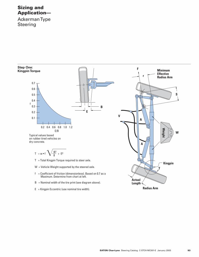
Typical values basedon rubber tired vehicles ondry concrete.
0.8 1.0 1.2
T = w • f
T = Total Kingpin Torque required to steer axle.
W = Vehicle Weight supported by the steered axle.
f = Coefficient of friction (dimensionless). Based on 0.7 as a Maximum. Determine from chart at left.
B = Nominal width of the tire print (see diagram above).
E = Kingpin Eccentric (use nominal tire width).
B2
8 + E2
Step One:Kingpin Torque

94 EATON Char-Lynn Steering Catalog C-STOV-MC001-E January 2003
Sizing andApplicationAckerman TypeSteering Continued
Differential Cylinder Cross Connected Cylinder
Balanced Cylinder Opposed Cylinder
D = 4A + d2
D = 2A d2
2+
D = 4A
D =D
4A + d2
d
Note: dD
.152( )( )
Step Two:
Force Required
F = Tr
F = Force required for the axle.T = Kingpin torque as determined in Step 1.
The value calculated in Step 1 is the total torque for theaxle. If the steered axle is power driven, double this valueto approximate the additional dynamic loads.
r = Effective radius arm about the kingpin axis at which the cylinder force is applied. The effective radius is theminimum distance from kingpin to the axis of the cylinder… not the actual length of the arm.
Cylinder Area
A = FP
A = Cylinder area for the axle cylinder set.F = Force requiredP = Hydraulic pressureFor vehicle with a steered axle that can never be overloaded use 80% of the steering circuit relief valve setting. For manuallyloaded vehicles use 60%. For vehicles that can be severelyoverloaded use 30%.
Cylinder Diameter
Once the required cylinder set area is determined, the cylinder diameter can be calculated.D = Inside diameter of cylinder.d = Rod diameter as required.
Cylinder Stroke
S = Stroke LengthThe cylinder stroke is determined by axle geometry. That is, therequired stroke is a function of the radius arm and the total anglethrough which the arm turns.
d2V = S x4
2D2 —Cross ConnectedCylinder
d2V = S x 4
D2 — Differential Cylinder(Small Volume orBalanced Cylinder)
V = S x 4
x D2Differential Cylinder(Large Volume)
Cylinder Volume V = Volume V = S x A
( )( )( )( )
The volume of oil required to move cylinder rod(s) throughthe entire stroke.

EATON Char-Lynn Steering Catalog C-STOV-MC001-E January 2003 95
Sizing andApplicationAckerman TypeSteering Continued
Step Three:
Selecting Steering
Unit Displacement
Before proceeding further, a decision must be made as to thenumber of steering wheel revolutions desired for the applicationto steer the axle from full one side to the other. Depending onvehicle usage, this will vary, normally 2 1/2 to 5 1/2 with 4 being a good typical value
Displ. = VN
V = Volume full strokeN = number of steering wheel revolutions lock
to lockOnce this calculation is complete, select the closest standard steering unit displacementfrom the catalog information.Now the number of steering wheel revolutions should berecalculated.
N = Vdispl.
displ. = Steering unit displacement per revolution. Note: for different cylinder applications, the cylinder volume willbe different for right and left turns and the value N will varyaccordingly.
Step Four:
Calculating Required
Pump Flow
Pump sizing is important to assure adequate power for steeringunder all operating conditions. The required pump flow can becalculated by the following equation.QP = Rmax. x displ.QP (L/min): Required pump flow.Rmax = Max. steering wheel input of steering control
unit (SCU).displ. = Displacement of steering control unit per
revolution. Before proceeding to evaluation required pump flow themaximum required steering wheel speed must be determined.Typically 120 revolutions per minute (RPM) is used for Rmax.• It is important at engine
low idle condition that the maximum steering wheel speedshould be more than 60 rpm.
• For engine normal idle condition, maximum steering wheel speed should be morethan 100 rpm if possible.
• When using open center SCU connected with pump directly,maximum pump flow should be less than 1.4 times of SCU rated flow. Higher flow into SCU increases pressure-loss of thesteering system. If higher flow is unavoidable, install a flowdivider valve into the system or use a load sensing system.

Parker Hannifin CorporationHydraulic Pump/Motor DivisionGreeneville, Tennessee USA
Hydrostatic Steering Unit
12
Catalog HY13-1560-002/US
1560-002.P65,pm
.2 .4 .6 .8 1.0 1.2
.1.2.3.4
.5
.6
.7
mu
EB
STEP I CalculateapproximateKingpin torque(KT)
1.1 Determine coefficientof friction:Select the coefficient offriction (mu) from Chart 1after calculating E/B.(Kingpin offset/nominal tirewidth). See Diagram 1.
Chart 1 (Rubber tires ondry concrete)
Diagram 1
1.2 Calculate Kingpintorque:
B2
KT= W (mu) — + E2
8
NOTE: If steered axlewheels are driven(powered), double KT.
Where:KT = Kingpin torque
in inch-poundsW = Weight on steered
axle in pounds(Use maximumoverloaded weightanticipated.)
mu = Coefficient offriction
B = Nominal Tire width(inches)
E = Kingpin offset(inches) at theintersection withthe ground
STEP II Select steeringunit
For small garden tractor-typevehicles, select an HGF —for larger vehicles selectHGA or HGB. The purposeof this is to establish whatpressure to use in Step IV.
STEP III Calculateapproximatecylinder force(CF)
KTCF = ——
RWhere:
KT = Kingpin torque(inch-pounds)
R = Minimum radiusarm (inches)(see Diagram 2)
Diagram 2
_______√
System Design Process
STEP IV Calculatecylinder area(CA)
CFCA = ——
P
Where:CF = Cylinder force
(pounds)P = Pressure (psi)
(This is thepressure rating ofthe steering unitchosen.)
Select the next largercommon cylinder bore sizeavailable. If one cylinder isused, use the rod end areaonly and, if two are used,use the rod end area plusthe head end area to selectthe cylinder (Step VI).
STEP V Determinecylinder stroke
Calculate using diagram 2as a guide and the desiredvehicle turning circle.
STEP VI Calculateswept volume(SV) of thecylinder(s)
6.1. One balanced cylinder,double acting
SV = (Bore area - rodarea) x cylinderstroke
πSV = — [B2 - R2] x S
4
6.2. One unbalancedcylinder, double acting
a. Head side
π x B2
SV = ——— x S 4
b. Rod side Same as 6.1 above
BE
f
Stroke
Minimum RadiusArm = R

Hydrostatic Steering Unit
Parker Hannifin CorporationHydraulic Pump/Motor DivisionGreeneville, Tennessee USA
13
Catalog HY13-1560-002/US
1560-002.P65, pm
6.3. Two unbalancedcylinders, doubleacting
π x SSV = ——— (2B2 - R2)
4
Where:SV = Swept volume
(volume of oil tomove cylinder fullstroke) in cubicinches
B = Bore diameter(inches)
R = Rod diameter(inches)
S = Cylinder stroke(inches)
STEP VII CalculateHydraguide™displacement(HD)
SVHD = ——
n
Where:SV = Swept volume in
cubic inches fromStep VI
n = Number of steeringwheel turns lock-to-lock (from one endof cylinder stroke tothe other). Thisranges from 3 to 6depending on thetype of vehicle.
When one single rodcylinder is used, calculate nfor each direction because itwill be different. Select thenext closest displacement. Ifdesired, recalculate n asfollows:
SVn = —————————— Displacement of selected
Hydraguide™
STEP VIII Calculateminimumpump flow(Q)
HD x SS x 60Q = ——————
231
If the steering wheel speedbecomes greater than thepump flow, a dramaticincrease in steering wheeleffort is felt.
STEP IX Measuremaximumsteeringpressureon prototypevehicle
Compare this pressure withthe pressure rating of theHydraguide. If it is higher,return to the last part of StepIII and recalculate throughStep IX again.
STEP X Select a reliefvalve setting
The cracking pressure of therelief valve, which is usuallydefined as the pressurewhen the relief valve startsto open and discharge flowto the return line, should begreater than the maximumpressure measured on thevehicle.
The full flow pressure of therelief valve, which is definedas the pressure whenmaximum flow is going overthe relief valve, must notexceed the pressure ratingon the steering unit.
NOTE:Reversing units used withbalanced area cylinders.
System Design Process
Where:Q = Pump flow (gallons/
minutes/revolutions)
HD = Hydraguidedisplacement(cubic inches)
SS = Steering speed(revolutions/seconds)(Ideal speed ofsteer = 120 rpms.)
Steering Speed
The minimum normallyconsidered is 1 rev/sec (60rpm). An example would bean articulated vehicle. Thisdepends on the safetyconsiderations foravoidance of obstaclesunder minimum andmaximum flow conditionsduring all speed possibilitiesof the vehicle.
1.5 rev/sec (90 rpm) iscommon, and 2 rev/sec (120rpm) is considered about themaximum input speedachievable by an averageperson.
HGF SeriesOpen CenterClosed CenterPower Beyond
Operating Parameters:1800 PSI8 GPM3.3 to 9.9 cu. in.
Typical Systems:Turf, Material Handling, General Purpose,and Light Agricultural Vehicles.