sizing, selection, and installation of pressure...
TRANSCRIPT

API RP520 Part 2, Sixth Edition, Draft 8
Sizing, Selection, and Installation of Pressure-Relieving Devices in Refineries
Part 2 – Installation
5/6/2023 – Draft 8 Page 1 of 58

CONTENTS1. Scope........................................................................................................................... 52. References...................................................................................................................5
2.1 Normative References...........................................................................................52.2 Informative References.........................................................................................5
3. Definition of Terms.......................................................................................................54. Inlet Piping To Pressure Relief Devices.......................................................................5
4.8 GENERAL REQUIREMENTS...............................................................................54.8.1 Flow and Stress Considerations.....................................................................54.8.2 Vibration Considerations................................................................................6
4.9 PRESSURE-DROP LIMITATIONS AND PIPING CONFIGURATIONS................64.9.1 Pressure Loss at the Pressure Relief Valve Inlet...........................................64.9.2 Size and Length of Inlet Piping To Pressure Relief Valves............................74.9.3 Sizing of Inlet Piping for Rupture Disk/Pressure Relief Valve Combination Installations.................................................................................................................104.9.4 Sizing of Inlet Piping for Thermal Relief Valves for Ambient Heating...........104.9.5 Sizing of Inlet Piping for Thermal Relief Valves from Process.....................104.9.6 Remote Sensing for Pilot-Operated Pressure Relief Valves........................104.9.7 Configuration of Inlet Piping for Pressure Relief Valves...............................11
4.10 INLET STRESSES THAT ORIGINATE FROM STATIC LOADS IN THE DISCHARGE PIPING.....................................................................................................11
4.10.1 Thermal Stresses.........................................................................................124.10.2 Mechanical Stresses....................................................................................12
4.11 INLET STRESSES THAT ORIGINATE FROM DISCHARGE REACTION FORCES........................................................................................................................12
4.11.1 Determining Reaction Forces In An Open Discharge System......................124.11.2 Determining Reaction Forces in a Closed Discharge System......................13
4.12 ISOLATION VALVES IN INLET PIPING.............................................................144.13 RUPTURE DISK DEVICES IN COMBINATION WITH PRESSURE RELIEF VALVES.........................................................................................................................144.14 PROCESS LATERALS CONNECTED TO INLET PIPING OF PRESSURE RELIEF VALVES............................................................................................................144.15 TURBULENCE IN PRESSURE RELIEF DEVICE INLETS.................................14
5. DISCHARGE PIPING FROM PRESSURE RELIEF DEVICES...................................145.1 GENERAL REQUIREMENTS.............................................................................145.2 SAFE DISPOSAL OF RELIEVING FLUIDS........................................................145.3 BACK PRESSURE LIMITATIONS AND SIZING OF PIPE..................................15
5.3.1 General........................................................................................................155.3.2 Thermal Relief Valves..................................................................................15
5.4 CONSIDERATIONS FOR PILOT-OPERATED PRESSURE RELIEF VALVES. .155.5 STRESSES IN DISCHARGE PIPING DURING RELEASE.................................155.6 ISOLATION VALVES IN THE DISCHARGE PIPING..........................................165.7 RUPTURE DISKS INSTALLED AT OUTLET OF PRESSURE RELIEF VALVE. 16
6. ISOLATION (STOP) VALVES IN PRESSURE RELIEF PIPING................................166.1 GENERAL...........................................................................................................16
5/6/2023 – Draft 8 Page 2 of 58
6.2 APPLICATION.....................................................................................................166.3 ISOLATION VALVE REQUIREMENTS...............................................................16
6.3.1 Installation of Spare Relief Capacity............................................................176.3.2 Three-Way Changeover Valves For Dual Pressure Relief Device Installations.................................................................................................................186.3.3 Use of Ball Valves as Three-Way Changeover Valve..................................18
6.4 EXAMPLES OF ISOLATION VALVE INSTALLATIONS......................................196.5 ADMINISTRATIVE CONTROLS RELATED TO ISOLATION VALVES...............19
7. BONNET OR PILOT VENT PIPING...........................................................................197.1 GENERAL...........................................................................................................197.2 CONVENTIONAL VALVES.................................................................................197.3 BALANCED BELLOWS VALVES........................................................................19
7.3.1 General........................................................................................................197.3.2 Bonnet Vent for Bellows Valve Handling Non-Hazardous Vapors...............207.3.3 Bonnet Vent for Bellows Valve Handling Hazardous Vapors.......................207.3.4 Bonnet Vent for Bellows Valve Handling Non-Hazardous Liquids...............207.3.5 Bonnet Vent for Bellows Valve Handling Hazardous Liquids.......................20
7.4 BALANCED PISTON VALVES............................................................................207.5 PILOT-OPERATED VALVES..............................................................................20
8. DRAIN PIPING...........................................................................................................218.1 INSTALLATION CONDITIONS THAT REQUIRE DRAIN PIPING......................218.2 SAFE PRACTICE FOR INSTALLATION OF DRAIN PIPING..............................21
9. PRESSURE RELIEF DEVICE LOCATION AND POSITION......................................219.1 INSPECTION AND MAINTENANCE...................................................................219.2 PROXIMITY TO PRESSURE SOURCE..............................................................219.3 PROXIMITY TO OTHER EQUIPMENT...............................................................21
9.3.1 Reducing Stations........................................................................................229.3.2 Orifice Plates And Flow Nozzles..................................................................229.3.3 Other Valves And Fittings.............................................................................22
9.4 MOUNTING POSITION.......................................................................................229.5 TEST OR LIFTING LEVERS...............................................................................229.6 HEAT TRACING AND INSULATION...................................................................22
10. BOLTING AND GASKETING..................................................................................2310.1 CARE IN INSTALLATION...................................................................................2310.2 PROPER GASKETING AND BOLTING FOR SERVICE REQUIREMENTS.......23
11. MULTIPLE PRESSURE RELIEF VALVES WITH STAGGERED SETTINGS.........2312. INSTALLATION OF RUPTURE DISKS IN SERIES................................................2313. PRE-INSTALLATION HANDLING AND INSPECTION...........................................24
13.1 GENERAL...........................................................................................................2413.2 STORAGE AND HANDLING OF PRESSURE RELIEF DEVICES......................2413.3 INSPECTION AND TESTING OF PRESSURE RELIEF VALVES......................2413.4 INSPECTION OF RUPTURE DISK DEVICES....................................................2413.5 INSPECTION AND MAINTENANCE OF PIN-ACTUATED DEVICES.................2513.6 INSPECTION AND CLEANING OF SYSTEMS BEFORE INSTALLATION........25
Figure 1 – Typical Pressure Relief Valve Installation: Atmospheric (Open) Discharge.. . .26Figure 2 – Typical Pressure Relief Valve Installation: Closed System Discharge............27
5/6/2023 – Draft 8 Page 3 of 58

Figure 3 - Typical Rupture Disk Device Installation: Atmospheric (Open) Discharge......28Figure 4 – Typical Pressure Relief Valve Mounted on Process Line.................................29Figure 5 – Typical Pressure Relief Valve Mounted on Long Inlet Pipe..............................30Figure 6 – Typical Pilot-Operated Pressure Relief Valve Installation.................................31Figure 7 – Typical Pressure Relief Valve Installation with Vent Pipe.................................32Figure 8 - Typical Rupture Disk Device In Combination With Relief Valve: Inlet Side Installation.......................................................................................................................33Figure 9 – Avoiding Process Laterals Connected to Pressure Relief Valve Inlet Piping...34Figure 10 – Typical Pressure Relief Device Installation with an Isolation Valve...............35Figure 11 – Typical Pressure Relief Device Installation for 100 Percent Spare Relieving Capacity.............................................................................................................................36Figure 12 – Alternate Pressure Relief Device Arrangement for 100 Percent Spare Relieving Capacity.............................................................................................................37Figure 13 – Alternate Pressure Relief Device Installation Arrangement for 100 Percent Spare Relieving Capacity..................................................................................................38Figure 14 – Three-Way Changeover Valve – Shuttle Type...............................................39Figure 15 – Three-Way Changeover Valve – Rotor Type..................................................40Figure 16 – Three-Way Changeover Valve – Ball Types...................................................41Figure 17 – Typical Flare Header Block Valves.................................................................42Figure 18 – Typical Isolation Block Valves for Spare Compressor....................................43Figure 23 – Typical Installation Avoiding Unstable Flow Patterns at Pressure relief Valve Inlet....................................................................................................................................48APPENDIX A – RUPTURE DISK INSTALLATION GUIDELINES.....................................49Figure A.1 – Typical Configuration of Companion Flanges, Gaskets and Rupture Disk Assembly...........................................................................................................................53Figure A.2 – Proper Handling of a Rupture Disk................................................................54Figure A.3 – Improper Handling of a Rupture Disk............................................................54Figure A.4 – Proper Alignment of Rupture Disk indicated by Tag Arrows.........................55APPENDIX B – INSTALLATION & MAINTENANCE OF PIN-ACTUATED NON-RECLOSING PRESSURE RELIEF DEVICES...................................................................55APPENDIX C – TECHNICAL INQUIRIES.........................................................................57Bibliography.......................................................................................................................58
5/6/2023 – Draft 8 Page 4 of 58

Sizing, Selection, and Installation of Pressure-Relieving Devices in Refineries
Part II – Installation
1. ScopeThis Standard covers methods of installation for pressure relief devices for equipment that has a maximum allowable working pressure (MAWP) of 15 psig (1.03 bar g or 103 kPA) or greater. Pressure relief valves or rupture disks may be used independently or in combination with each other to provide the required protection against excessive pressure accumulation. As used in this recommended practice, the term pressure relief valve includes safety relief valves used in either compressible or incompressible fluid service, and relief valves used in incompressible fluid service. This recommended practice covers gas, vapor, steam, two-phase and incompressible fluid service; it does not cover special applications that require unusual installation considerations.
2. ReferencesThe current editions of the following standards, codes, and specifications are cited in this standard:
2.1 Normative ReferencesAPI
STD 520 Sizing, Selection, and Installation of Pressure–Relieving Devices in Refineries, Part 1 – Sizing and Selection
STD 526 Flanged Steel Pressure Relief Valves
ISO 23251(API STD 521) Guide for Pressure-Relieving and Depressuring Systems
RP 576 Inspection of Pressure Relieving Devices
2.2 Informative References
ASME1
B31.3 Process Piping
Boiler and Pressure Vessel Code, Section VIII, “Pressure Vessels”
3. Definition of TermsThe terminology for pressure relief devices that is used in this standard is in general agreement with the definitions given in API STD 520 Part 1.
4. Inlet Piping To Pressure Relief Devices
4.1 GENERAL REQUIREMENTSFor general requirements for inlet piping, see Figures 1 through 3.
1 ASME International, Three Park Avenue, New York, New York 10016-5990, www.asme.org.
5/6/2023 – Draft 8 Page 5 of 58

4.1.1 Flow and Stress ConsiderationsInlet piping to the pressure relief devices should provide for proper system performance. This requires design consideration of the flow-induced pressure drop in the inlet piping. Excessive pressure losses in the piping system between the protected vessel and a pressure relief device will adversely affect the system-relieving capacity and can cause valve instability. In addition, the effect of stresses derived from both pressure relief device operation and externally applied loads should be considered. For more complete piping design guidelines, see ASME B31.3.
4.1.2 Vibration ConsiderationsMost vibrations that occur in inlet piping systems are random and complex. These vibrations may cause leakage at the seat of a pressure relief valve, premature opening, or premature fatigue failure of certain valve parts, inlet and outlet piping, or both. Vibration in inlet piping to a rupture disk may adversely affect the burst pressure and life of the rupture disk.
Detrimental effects of vibrations on the pressure relief device can be reduced by minimizing the cause of vibrations, by additional piping support, by use of either pilot-operated relief valves or soft-seated pressure relief valves, or by providing greater pressure differentials between the operating pressure and the set pressure.
4.2 PRESSURE-DROP LIMITATIONS AND PIPING CONFIGURATIONSFor pressure-drop limitations and piping configurations, see Figures 1, 2, 4 and 5.
4.2.1 Pressure Loss at the Pressure Relief Valve Inlet
4.2.1.1 GeneralThe objectives for the evaluation of the changes in pressure en route to the pressure relief valve inlet are the following:
a. To provide a reasonable assurance that the inlet pressure losses are unlikely to result in destructive chattering of the pressure relief valve,
b. To ensure the inlet pressure losses do not significantly affect the capacity of the pressure relief valve without the user designing appropriately for those effects, and
c. To ensure the pressure relief valve will open before the maximum allowable working pressure is exceeded for any piece of equipment being protected and will limit the relieving pressure to the maximum allowable accumulation limits for all equipment being protected.
4.2.1.2 Pressure Relief Valve StabilityPressure relief valve stability can be affected by many factors. These include:
Excessive Inlet line frictional losses
Acoustic frequency of the inlet system matches the natural frequency of the valve
Excessive outlet built-up back pressure on conventional valves (see 5.3.1), including the effects of back pressure generated in the body bowl of the valve
Acceleration of liquids in long inlet lines
Excessive relief valve capacity
Insufficient upstream capacitance (e.g., a location downstream of a pressure regulator).
Excessive pressure loss at the inlet of a spring loaded or integrally sensed pop action pilot operated pressure relief valve can cause rapid opening and closing of the valve, or chattering. Although modulating pilot operated valves or remotely sensed pop action pilot operated valves will be less likely to chatter due to
5/6/2023 – Draft 8 Page 6 of 58

high inlet pressure losses, the valve’s capacity shall be evaluated using the lower inlet pressure (see 4.2.1.3).
Chattering will result in lowered capacity and damage to the seating surfaces, and can lead to adverse effects on the pressure relief valve itself and/or the connecting piping. The pressure loss that affects valve performance is caused by non-recoverable entrance losses (turbulent dissipation) and by friction within the inlet piping to the pressure relief valve.
4.2.1.3 Pressure Relief Valve CapacityThe pressure relief valve sizing equations presented in API STD 520 Part I are based on nozzle flow equations which use the stagnation pressure at the inlet to the nozzle as a fundamental input variable. Any non-recoverable pressure losses that occur from the protected equipment to the inlet flange of the pressure relief valve reduce the stagnation pressure at the inlet nozzle. This reduction in pressure directly reduces the capacity of the pressure relief valve. In typical installations where the 3% criterion as detailed in 4.2.2.2.1 is satisfied, the magnitude of the non-recoverable pressure losses is not expected to be significant and the effects of those pressure losses are typically neglected when determining the valve capacity. If the inlet loss exceeds 3%, the calculated pressure at the inlet to the PRV shall be used to determine the capacity of the valve.
4.2.1.4 Adjustments to Set Pressures Based on Upstream SystemThe set pressure of a pressure relief valve is typically based on the MAWP or design pressure of the protected equipment, although other limiting pressures may become the basis for selecting the set pressure. The changes in the pressure between the protected equipment and the pressure relief valve should be evaluated to ensure that the opening pressure does not exceed the maximum allowed per code and to ensure that the maximum allowable accumulated pressure is not exceeded while relieving. Example installations where this can be a concern include:
a. Static liquid head between the protected equipment and the relief valve: Typically, the liquid static head is taken into account by reducing the set pressure of the PRV by the equivalent static liquid head. However, the liquid head is not included in the flowing inlet pressure loss calculation because it is separate from the flowing pressure drop.
b. Interconnected process equipment protected by a common pressure relief valve: The set pressure of the common pressure relief valve may need to be adjusted downward based on the pressure profile at the time of the upset to ensure that the valve opens before pressure at any protected equipment in the system exceeds that allowed by the design code. Further, any change in the pressure profile after the valve opens needs to be evaluated to ensure that the maximum allowable accumulated pressure is not exceeded on any of the protected equipment.
c. Pressure relief valve located on process piping away from the protected equipment: An example is where a pressure relief valve is located on a tower's overhead piping. The set pressure of the pressure relief valve may need to be adjusted downward based on the pressure profile at the time of the upset to ensure that the valve opens before pressure at any protected equipment in the system exceeds that allowed by the design code. Further, any change in the pressure profile after the valve opens needs to be evaluated to ensure that the maximum allowable accumulated pressure is not exceeded on any of the protected equipment.
4.2.2 Size and Length of Inlet Piping To Pressure Relief Valves
4.2.2.1 Size of Inlet Piping ComponentsThe nominal size of the inlet piping and fittings shall be the same as or larger than the nominal size of the pressure relief valve inlet connection as shown in Figures 1 through 3.
5/6/2023 – Draft 8 Page 7 of 58

4.2.2.2 Inlet Pressure Loss Limits - 3% Rule
4.2.2.2.1 General When a pressure relief valve is installed on a line directly connected to a vessel, the total non-recoverable pressure loss between the protected equipment and the pressure relief valve should not exceed 3 percent of the set pressure of the pressure relief valve except as permitted in 4.2.2.4 when supported by an engineering analysis, 4.2.4 for thermal relief valves and 4.2.6 for pilot-operated pressure relief valves. When a pressure relief valve is installed on a process line, the 3 percent limit should be applied to the sum of the loss in the normally non-flowing pressure relief valve inlet pipe and the incremental pressure loss in the process line caused by the flow through the pressure relief valve.
4.2.2.2.2 Establishing Non-recoverable LossesAs discussed in 4.2.2.2.1, only non-recoverable pressure losses in the inlet piping need to be included in the pressure drop calculations.
Friction losses are "non-recoverable". Friction losses include both wall friction and turbulent dissipation for pipe and fittings (valves, reducers, expanders, etc.). The entrance loss from the protected equipment to the inlet line should be included as well.
Kinetic energy losses, including the pressure loss as a result of the flow impinging on the valve disc, are considered recoverable and do not need to be included in the pressure drop calculations. However, even when kinetic energy losses are non-recoverable, they are small in comparison with other losses and therefore can be neglected.
Liquid static head is not included in the pressure loss calculation because it is separate from the flowing pressure drop. See 4.2.1.4.a for the effect of static head on set pressure.
4.2.2.2.3 Rated Capacity vs. Required FlowThe pressure loss should be calculated using the rated capacity of the pressure relief valve. However, there are some instances where the required relief rate may be used, although the user is cautioned that this creates a constraint in the system. Any future increases in the required rate may necessitate an increase in the size of the inlet piping even though the valve has sufficient capacity.
The pressure loss may be calculated using the required relief rate in certain applications. Examples include, but are not limited to, the following cases:
pressure relief valves having modulating characteristics as indicated by the pressure relief valve manufacturer. This is clearly the case for modulating pilot-operated relief valves. Some spring-loaded valves have modulating tendencies; consult the manufacturer for this case. Again, the user is cautioned about constraints imposed in the design when inlet piping is sized based on required flow.
Also, in cases involving incompressible fluids (i.e., a subcooled liquid that does not flash prior to or within the pressure relief valve) where the flow through a liquid-trim pressure relief valve is physically limited to the relief requirement, the pressure loss may be calculated using the required relief rate. Examples of cases where flow is physically limited include hydraulic expansion of an isolated liquid in a small volume (See 4.2.3) or flow directly from a pump.
4.2.2.3 Design Options to Address High Inlet Pressure DropKeeping the pressure loss below 3 percent becomes progressively more difficult at low pressures and/or as the orifice size of a pressure relief valve increases. In certain applications, it is difficult to meet the 3% rule for the largest API 526 orifice size for a given inlet flange diameter (e.g. 2J3, 4P6, 6R8, etc.). There are some non-API 526 valves that also exhibit this behavior.
Pressure losses can be reduced by making modifications to the system design, including but not limited to the following:
rounding the entrance to the inlet piping,
5/6/2023 – Draft 8 Page 8 of 58

reducing the inlet line length,
reducing the number of fittings,
installing a different type of fitting (i.e. lower equivalent length)
increasing the diameter of the inlet piping. ensuring that the relief capacity is well-matched to the required rate.
selecting multiple smaller valves with independent inlet piping
An option for mitigating excessive inlet losses is to use a pilot-operated relief valve with remote sensing (see 4.2.6), if the application permits.
4.2.2.4 Engineering Analysis to Exceed 3% Inlet LossesThe 3% inlet loss limitation for PRVs was first discussed in an API sponsored report published by the University of Michigan in 1948 [1]. In this report, it is clear that the inlet loss limitation was solely related to a blowdown value of 4%. Additional work in 1963 indicating that the 3% rule was based on blowdown is provided in [2]. In this paper, a 5% blowdown was assumed.
Today, a typical blowdown set by the manufacturer for a PRV is 7 to 12% of the set pressure. Because the original basis related the allowable inlet losses to blowdown settings in the range of 4 - 5 %, inlet losses above the 3% limitation may be appropriate with higher blowdown settings. A suitable margin relative to the blowdown shall be specified by the user.Note that the set pressure tolerance allowed by construction codes does not affect the margin between set pressure and blowdown.
a. If the inlet losses are allowed to exceed the 3% criteria, an engineering analysis of the pressure relief valve performance at higher inlet losses s shall be performed, and documented. The engineering analysis shall include but is not limited to the following:Verification from the manufacturer of minimum blowdown value of the PRV model based on the manufacturer’s standard setting. The user shall verify that the original blowdown setting of the valve has not been altered. If the blowdown setting of the specific valve being evaluated is not within the standard setting then the manufacturer shall be consulted to determine the actual blowdown. In many cases, this will require additional testing by the manufacturer.
b. Prior to any increase in blowdown to allow for higher inlet pressure drop, the manufacturer shall be consulted to make sure that an increase in blowdown is possible and any adjustment will not result in a reduction in the required lift. In many cases, this will require additional testing by the manufacturer.
c. Re-evaluation of the flow capacity of the valve taking into consideration the reduction in pressure at the inlet to the valve.
d. The user shall conduct a thorough review of the valve’s inspection/maintenance records and obtain experience from Operations, to identify any indications of chatter. Any evidence of chatter should be followed by a redesign of the inlet system.
Note that the engineering analysis described above addresses only one of the mechanisms that are known to contribute to instability of pressure relief devices (see 4.2.1.2). The user should be aware that limiting the inlet pressure drop does not necessarily eliminate all causes of instability.
4.2.3 Sizing of Inlet Piping for Rupture Disk/Pressure Relief Valve Combination InstallationsWhen rupture disk device is used in combination with a pressure relief valve, the pressure-drop calculation shall include the additional pressure drop developed by the disk (See 4.6 for additional information on rupture disk devices).
5/6/2023 – Draft 8 Page 9 of 58

4.2.4 Sizing of Inlet Piping for Thermal Relief Valves for Ambient HeatingThe inlet piping for thermal relief valves designed solely to protect against liquid hydraulic expansion due to ambient heating (including solar radiation) typically does not need to be sized to meet the inlet loss requirements of 4.2.2.1. The reason for this is that the rated capacity of these PRVs are larger by an order of magnitude (>10 times) than the required relief rate and the flow in the inlet line never reaches a steady state flow at the rated capacity.
Some examples where inlet pressure drop calculations for thermal relief valves where the pressure is generated by ambient heating may need to be considered are the following:
a. Piping containing refrigerated liquids
b. Piping containing fluids that may vaporize when exposed to ambient heating (e.g. LPG)
c. Applications (e.g. long pipelines or large liquid-filled vessels) where the required flowrate due to thermal expansion approaches the rated capacity of the valve
The user is cautioned that some applications of thermal expansion due to process heating, such as heat exchangers or equipment that is exposed to heat tracing, can have significantly more heat transfer, and the inlet pressure drop may need to be evaluated (see 4.2.5).
For thermal relief valves that can open as a result of being connected to a system that has other credible overpressure scenarios, the user is cautioned that the inlet piping to the valve should be designed to meet the inlet loss requirements of 4.2.2.1 for those scenarios.
4.2.5 Sizing of Inlet Piping for Thermal Relief Valves from Process Note that inlet piping for thermal relief devices shall always be sized to meet the inlet loss requirements of 4.2.2.1 for applications where pressure inside the protected equipment can be generated by process heat. Examples of these applications include:
a. Cold side of heat exchangers when blocked in an exposed to hot side fluid temperature
b. Piping and vessels heated by steam or electric tracing
4.2.6 Remote Sensing for Pilot-Operated Pressure Relief ValvesRemote sensing permits the pilot to sense system pressure at a location that most accurately reflects the actual pressure of the protected system. Remote sensing will mitigate the effect of excessive inlet pressure losses due to the inlet piping configuration (see Figure 6). The addition of a remote sense line allows the pilot to correctly sense system pressure and to keep the valve from rapid cycling or chattering due to high inlet piping pressure losses. Relieving capacity will be proportionately reduced whenever there is inlet pressure loss to the valve (see 4.2.1.3).
4.2.6.1 Inlet Pipe LossRemote sensing permits the pilot to sense the system pressure upstream of the inlet piping loss. Remote sensing may eliminate uncontrolled valve cycling or chattering for a pop action pilot-operated pressure relief valve and will permit a modulating pilot-operated pressure relief valve to achieve full lift at the required overpressure.
Although remote sensing may eliminate valve chatter or permit a modulating pilot-operated pressure relief valve to achieve full lift at the required overpressure, any pressure drop in the inlet pipe will reduce the relieving capacity (see 4.2.1.3).
4.2.6.2 Installation GuidelinesRemote sensing lines should measure static pressure where the velocity is low. Otherwise, the pilot will sense an artificially low pressure due to the effect of velocity.
Ensure that the pilot sensing point is within the system protected by the main valve.
5/6/2023 – Draft 8 Page 10 of 58

For flowing pilots, remote sensing lines shall be sized to limit the pressure loss to 3 percent of the set pressure based on the maximum flow rate of the pilot at 110 percent of set pressure. Consult the manufacturer for size recommendations for the remote sensing line.
For non-flowing pilots, remote sensing lines with a flow area of 0.070 in2 (45 mm2) should be sufficient since no system medium flows through this type of pilot when the main valve is open and relieving. Consult the manufacturer for remote sensing line size recommendations.
Consider using pipe for remote sensing lines to ensure mechanical integrity. Additionally, corrosion resistance should be considered when selecting material of construction for the sense line.
If a block valve is installed in the remote sensing line, the guidelines in Section 6 should be followed. A closed block valve in a remote sensing line renders the pressure relief valve inoperative and may allow the valve to open.
4.2.7 Configuration of Inlet Piping for Pressure Relief ValvesAvoid the installation of a pressure relief valve at the end of a long horizontal inlet pipe through which there is normally no flow. Foreign matter may accumulate, or liquid may be trapped, creating interference with the valve’s operation or requiring more frequent valve maintenance.
The inlet piping system to pressure relief devices should be free-draining to prevent accumulation of liquid or foreign matter in the piping.
4.3 INLET STRESSES THAT ORIGINATE FROM STATIC LOADS IN THE DISCHARGE PIPINGImproper design or construction of the discharge piping from a pressure relief device can set up stresses that will be transferred to the pressure relief device and its inlet piping. These stresses may cause a pressure relief valve to leak or malfunction or may change the burst pressure of a rupture disk. The pressure relief device manufacturer should be consulted about permissible loads.
4.3.1 Thermal StressesFluid flowing from the discharge of a pressure relief device may cause a change in the temperature of the discharge piping. A change in temperature may also be caused by prolonged exposure to the sun or to heat radiated from nearby equipment. Any change in the temperature of the discharge piping will cause a change in the length of the piping and may cause stresses that will be transmitted to the pressure relief device and its inlet piping. The pressure relief device should be isolated from piping stresses through proper support, anchoring, or flexibility of the discharge piping.
4.3.2 Mechanical StressesDischarge piping should be independently supported and carefully aligned. Discharge piping that is supported by only the pressure relief device will induce stresses in the pressure relief device and the inlet piping. Forced alignment of the discharge piping will also induce such stresses.
4.4 INLET STRESSES THAT ORIGINATE FROM DISCHARGE REACTION FORCESThe discharge of a pressure relief device will impose a reaction force as a result of the flowing fluid (see Figure 7). This force will be transmitted into the pressure relief device and also into the mounting nozzle and adjacent supporting vessel shell unless designed otherwise. The precise magnitude of the loading and resulting stresses will depend on the reaction force and the configuration of the piping system. The designer is responsible for analyzing the discharge system to determine if the reaction forces and the associated bending moments will cause excessive stresses on any of the components in the system. Requirements for design of piping systems to withstand reaction forces from pressure relief devices in steam service are given in ASME B31.3.
5/6/2023 – Draft 8 Page 11 of 58

The magnitude of the reaction force will differ substantially depending on whether the installation is open or closed discharge. When an elbow is installed in the discharge system to direct the fluid up into a vent pipe, the location of the elbow and any supports is an important consideration in the analysis of the bending moments.
4.4.1 Determining Reaction Forces In An Open Discharge System
4.4.1.1 Vapor DischargeThe following formula is based on a condition of critical steady-state flow of a compressible fluid that discharges to the atmosphere through an elbow and a vertical discharge pipe. The reaction force (F) includes the effects of both momentum and static pressure; thus, for any gas, vapor, or steam.
In US customary units,
In metric units,
where:
F = reaction force at the point of discharge to the atmosphere, lbf [N].
W = flow of any gas or vapor, lbm/hr [kg/s].
k = ratio of specific heats (Cp/Cv) at the outlet conditions.
Cp = specific heat at constant pressure.
Cv = specific heat at constant volume.
T = stagnation temperature at the pipe outlet, oR [K]. Note that the stagnation temperature is often not available. If this is the case, a suitable approximation is the relieving temperature. The user is cautioned that while this approximation is conservative for determination of reaction forces, the relieving temperature shall not be used for other piping design aspects as this does not consider auto-refrigeration or Joule-Thompson cooling effects.
M = molecular weight of the process fluid.
A = area of the outlet at the point of discharge, in2 [mm2].
P = static pressure within the outlet at the point of discharge, psig [kPa].
4.4.1.2 Two-Phase DischargeAlthough this paragraph provides a formula for the calculation of reaction forces for a two-phase release to atmosphere, the reader is cautioned to consider the decision for atmospheric discharge carefully. Due consideration should be given to the potential for liquid portions of the release causing a hazardous condition. Consult API STD 521 (ISO 23251) for additional guidance on atmospheric discharge.
The following formula can be used to determine the reaction force on inlet piping from an open discharge of a two-phase fluid. The formula assumes that the two-phase mixture is in homogenous flow condition (no-slip).
5/6/2023 – Draft 8 Page 12 of 58

In metric units,
where:
F = reaction force at the point of discharge to the atmosphere, lbf [N].
W = flowrate, lbm/hr [kg/s].
= weight fraction vapor at exit conditions
ρg = vapor density at exit conditions, lbm/ft3 [kg/m3].
ρl = liquid density at exit conditions, lbm/ft3 [kg/m3].
A = area of the outlet at the point of discharge, in2 [mm2].
P = static pressure within the outlet at the point of discharge, psig [kPa].
4.4.2 Determining Reaction Forces in a Closed Discharge SystemPressure relief devices that relieve under steady-state flow conditions into a closed system usually do not transfer large forces and bending moments to the inlet system, since changes in pressure and velocity within the closed system components are small.
Only at points of sudden expansion in the discharge piping will there be any significant inlet piping reaction forces to be calculated. Closed discharge systems, however, do not lend themselves to simplified analytical techniques. A complex time history analysis of the piping system may be required to obtain the reaction forces and associated moments that are transferred to the inlet piping system.
4.5 ISOLATION VALVES IN INLET PIPING Isolation valves located in the inlet piping to pressure relief devices shall be in accordance with the guidelines in Section 4.
4.6 RUPTURE DISK DEVICES IN COMBINATION WITH PRESSURE RELIEF VALVESA rupture disk device may be used as the sole pressure relief device, or it may be installed between a pressure relief valve and the vessel or on the downstream side of a pressure relief valve (see Figure 8).
When a rupture disk device is used between the pressure relief valve and the protected vessel, the space between the rupture disk and the pressure relief valve shall have a free vent, pressure gauge, trycock, or other suitable telltale indicator. A non–vented space with a pressure gage without alarms or other indication devices is not recommended as a suitable telltale indicator. Users are warned that a rupture disk will not burst in tolerance if back pressure builds up in a non–vented space between the rupture disk and the pressure relief valve, which will occur should leakage develop in the rupture disk due to corrosion or other cause. Only non-fragmenting rupture disk devices may be used beneath a pressure relief valve.
Rupture disks may not be available in all sizes at lower pressures; therefore, for these low-pressure applications the available rupture disk may have to be larger than the nominal size of the inlet piping and pressure relief valve.
5/6/2023 – Draft 8 Page 13 of 58

Refer to API STD 520, Part I for additional information related to the combination capacity factor when a rupture disk is installed in combination with a pressure relief valve.
4.7 PROCESS LATERALS CONNECTED TO INLET PIPING OF PRESSURE RELIEF VALVESProcess laterals should generally not be connected to the inlet piping of pressure relief valves (see Figure 9). Exceptions should be analyzed carefully to ensure that the allowable pressure drop at the inlet of the pressure relief valve is not exceeded under simultaneous conditions of rated flow through the pressure relief valve and maximum possible flow through the process lateral.
4.8 TURBULENCE IN PRESSURE RELIEF DEVICE INLETSSee 9.3 for information regarding the effects of turbulence on pressure relief valves.
5. DISCHARGE PIPING FROM PRESSURE RELIEF DEVICES
5.1 GENERAL REQUIREMENTSFor general requirements for discharge piping, see Figures 1, 2, 7, and 10.
The discharge piping installation shall provide for proper pressure relief device performance and adequate drainage (free-draining systems are preferred–see Section 8). Consideration should be given to the type of discharge system used, the back pressure on the pressure relief device, and the set-pressure relationship of the pressure relief devices in the system.
Auto-refrigeration during discharge can cool the outlet of the pressure relief device and the discharge piping to the point that brittle fracture can occur. Piping design, including material selection, shall consider the expected discharge temperature.
5.1 SAFE DISPOSAL OF RELIEVING FLUIDSFor a comprehensive source of information about the safe disposal of various relieving fluids, see ISO 23251 (API STD 521).
5.2 BACK PRESSURE LIMITATIONS AND SIZING OF PIPE
5.2.1 GeneralWhen discharge piping for pressure relief valves is designed, consideration should be given to the combined effect of superimposed and built-up back pressure on the operating characteristics of the pressure relief devices. The discharge piping system should be designed so that the back pressure does not exceed an acceptable value for any pressure relief device in the system. See API STD 520 Part 1 for limitations on back pressure.When rupture disks are used as the sole relieving device and the discharge is to a closed system, the effect of the superimposed back-pressure on the bursting pressure for the disk shall be considered.
The rated capacity of a conventional spring loaded, balanced spring loaded or pop action pilot-operated pressure relief valve should typically be used to size the atmospheric vent piping or the discharge line from the pressure relief valve to the relief header. Common relief header piping in closed discharge systems should be sized using the protected system’s required relieving capacity.
For a modulating pilot-operated pressure relief valve, the discharge piping can be sized using the required relieving capacity of the system that the valve is protecting.
Whenever the atmospheric vent, discharge piping or common relief header piping is sized using the system’s required relieving capacity instead of the rated capacity of the valve, the back pressure should be
5/6/2023 – Draft 8 Page 14 of 58

re-checked whenever changes are made to the process that effect the required relieving capacity of the system the valve is protecting. Additional information on sizing of discharge piping systems for vapor or gas service is covered in ISO 23251 (API STD 521).
5.2.2 Thermal Relief ValvesThe discharge piping from thermal relief valves designed solely to protect against liquid hydraulic expansion due to ambient heating (including solar radiation) typically does not need to be sized to meet the built-up back pressure limits provided in API 520 Part 1 and as discussed in 5.3.1. The reason for this is that the rated capacity of these PRVs are larger by an order of magnitude (>10 times) than the required relief rate and the flow in the discharge line never reaches a steady state flow at the rated capacity. See 4.2.3 for additional discussion and cautions with thermal relief valves.
Discharge piping for thermal relief valves in applications where pressure inside the protected equipment can be generated by process heat should be sized to meet the built-up back pressure limits provided in API 520 Part 1. See 4.2.4 for further details.
5.3 CONSIDERATIONS FOR PILOT-OPERATED PRESSURE RELIEF VALVESSuperimposed back pressure that exceeds the inlet pressure of a pilot-operated pressure relief valve can cause the main valve to open, allowing reverse flow through the main valve. For example, backflow can occur if several pressure relief valves have their outlets manifolded into a common discharge header, and one or more of these valves is discharging while another is connected to a system with a lower inlet pressure. An accessory should be specified that would prevent such backflow.
Purge systems for remote and integral sense lines may be required for certain applications prone to plugging. Special considerations are required if purge systems are used. In particular, the reliability of the purge flow should be ensured. The manufacturer should be consulted for additional recommendations.
5.4 STRESSES IN DISCHARGE PIPING DURING RELEASEThe reaction forces and stresses that originate in the downstream piping as a result of the release of a pressure relief device are typically not significant once flow is established and has reached steady state conditions, due to small changes in pressure and velocity within the closed system components. However, large forces may result if there are sudden pipe expansions within the system or as a result of unsteady flow conditions during the initial activation of the relief device. Additionally, large reaction forces can be created at elbows as a result of two-phase fluid flow in the slug flow regime.
The design of flare header piping in closed discharge systems should be in accordance with ASME B31.3. The design of flare header piping is not amenable to simplified analytical techniques, consequently, assistance by individuals knowledgeable in pipe stress analysis is recommended. A complex dynamic analysis of the system may be required. API RP521 gives additional guidance on the design of flare header piping.
5.5 ISOLATION VALVES IN THE DISCHARGE PIPINGIsolation valves located in the discharge piping system shall be in accordance with the guidelines provided in Section 6.
5.6 RUPTURE DISKS INSTALLED AT OUTLET OF PRESSURE RELIEF VALVEA rupture disk device may be installed on the outlet of a pressure relief valve to protect the valve from atmospheric or downstream fluids. Consideration shall be given to the pressure relief valve design so that it will open at its proper pressure setting regardless of any back pressure that may accumulate between the valve and rupture disk. See UG-127 of the ASME Boiler and Pressure Vessel Code, Section VIII for other requirements and considerations.
5/6/2023 – Draft 8 Page 15 of 58

6. ISOLATION (STOP) VALVES IN PRESSURE RELIEF PIPING
6.1 GENERALIsolation block valves may be used for maintenance purposes to isolate a pressure relief device from the equipment it protects or from its downstream disposal system. Since improper use of an isolation valve may render a pressure relief device inoperative, the design, installation, and administrative controls placed on these isolation block valves should be carefully evaluated to ensure that plant safety is not compromised.
A pressure relief device shall not be used as a block valve to provide positive isolation.
6.1 APPLICATIONIf a pressure relief device has a service history of leakage, plugging, or other severe problems that affect its performance, isolation and sparing of the pressure relief device may be provided. This design strategy permits the pressure relief device to be inspected, maintained, or repaired without shutting down the process unit. However, there are potential hazards associated with the use of isolation valves. The ASME Boiler and Pressure Vessel Code, Section VIII, Appendix M, discusses proper application of these valves and the administrative controls that shall be in place when isolation block valves are used. Local jurisdictions may have other requirements.
Additional examples of isolation valve installations are given in 6.4.
6.2 ISOLATION VALVE REQUIREMENTSIn addition to previously noted inlet and outlet pressure drop restrictions, isolation valves located in relief system piping shall meet the requirements specified below.Isolation (stop) valves are allowed upstream and/or downstream of the pressure relieving device for the purpose of inspection, testing, and repair of the pressure relieving device or discharge header isolation.
The opening through all pipe and fittings (including stop valves) between a pressure vessel and its pressure relief valve shall have at least the area of the pressure relief device inlet. Any pressure relief valve inlet isolation valves between equipment other than pressure vessels should also have at least the same nominal open area of the pressure relief valve inlet.
For outlet isolation valves, to help minimize the built-up back pressure, the flow area in the outlet isolation valve should be equal to or greater than the outlet area of the pressure relief valve.
Butterfly valves and globe valves have internal elements, may not be full area and typically are not designed for tight shut-off. In addition, there is the potential for internal failure of the butterfly valve causing an obstruction in the PRD inlet line. For these reasons, butterfly valves and globe valves are typically not used as pressure relief device isolation valves.
While butterfly valves are not recommended for usage as pressure relief device isolation valves, high-performance butterfly valves can be suitable for flare header isolation service. Butterfly valves used for these applications should be specified to a rigorous set of standards which assure that the disk will not fail in a position that will restrict flow and that provides a tight shut-off.
Check valves shall not be installed in pressure relief device inlet or outlet lines since these devices are normally closed and can become stuck in the closed position causing an obstruction in the pressure relief device path.
For pressure relief device inlet and outlet isolation valves:
a. Valves shall be suitable for the line service classification.
b. Valves shall be designed to be tight shut-off, where the valve is used for on-line maintenance.
5/6/2023 – Draft 8 Page 16 of 58

c. Valves shall have the capability of being locked or car-sealed open.
d. When gate valves are used, they shall be installed with stems oriented horizontally or, if this is not feasible, the stem shall be oriented downward to a maximum of 45º, from the horizontal to keep the gate from falling off and blocking the flow.
e. A bleed valve should be installed between the isolation valve and the pressure relief device to enable the system to be safely depressurized prior to performing maintenance. This bleed valve can also be used to prevent pressure build-up between the pressure relief device and the closed outlet isolation valve.
f. The PRV outlet isolation valve shall never be closed while the vessel is in operation without using an inlet isolation valve that has first been closed with the space between the inlet isolation valve and the pressure relief valve adequately depressured. Consideration should be given to using an interlocking system between the inlet and outlet isolation valves to assist with proper sequencing.
g. Consideration should be given to painting the isolation valve a special color or providing other identification.
When placing the pressure relief device into service, any outlet valve should be opened fully before beginning to open the inlet valve. Isolation valves should be opened gradually to help prevent unwanted opening of a pressure relief device due to the momentum of the fluid. The inlet and outlet isolation valves shall be open fully whenever the pressure relief valve is in service. Typical installations of isolation valves mounted at the inlet of pressure relief devices are shown in Figures 11 through 13. A typical installation of inlet and outlet isolation valves for pressure relief valves is shown in Figure 10.
6.2.1 Installation of Spare Relief CapacityIn corrosive and fouling services, or other services which may require frequent pressure relief device inspection and testing, consideration should be given to the installation of an additional relief device, so that 100 percent design relieving capacity is available while any pressure relief device is out of service. Examples of this type of installation are shown in Figures 11, 12 and 13. Consideration should be given to storing the spare pressure relief valves until needed, to preserve its integrity and allow bench testing just prior to installation.
When spare relief devices are provided, a mechanical interlock or administrative controls shall be provided which manages proper opening and closing sequences of the isolation valves to ensure that overpressure protection of the vessel or equipment is not compromised.
Typically the inlet isolation valves for spare relief devices are closed and the outlet isolation valves are open. The outlet isolation valve for spare relief devices can be closed during operation if exposure to the fluid is a concern, however, the pressure temperature rating of the pressure relief device outlet, the outlet isolation valve and intervening piping should be suitable for the conditions upstream of the relief device in case of leakage. Another method to protect the pressure relief device from discharge system fluids without closing the outlet isolation valve is to provide a purge.
Three-way changeover valves are acceptable in spare relief capacity applications provided the installation meets the size and inlet pressure drop requirements (see 6.3.4).
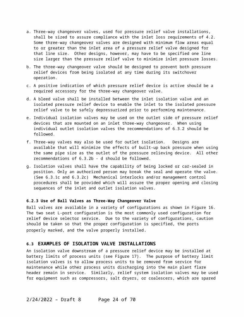
6.2.2 Three-Way Changeover Valves For Dual Pressure Relief Device Installations Three-way changeover valves are available, which are designed specifically for isolation valve service of dual pressure relief device installations. Such installations provide 100 percent of the design relieving capacity with one pressure relief device while a relief device is out of service. The second pressure relief device may be permanently mounted on the three-way changeover valve or may be stored until needed to preserve its integrity and allow bench testing just prior to installation. Three types of changeover valves are available: a three-way ball valve combined with piping on the inlet and outlet, the shuttle type (see Figure 14) and the rotor type (see Figure 15).
5/6/2023 – Draft 8 Page 17 of 58
a. Three-way changeover valves, used for pressure relief valve installations, shall be sized to assure compliance with the inlet loss requirements of 4.2. Some three-way changeover valves are designed with minimum flow areas equal to or greater than the inlet area of a pressure relief valve designed for that line size. Other designs, however, may have to be specified one line size larger than the pressure relief valve to minimize inlet pressure losses.
b. The three-way changeover valve should be designed to prevent both pressure relief devices from being isolated at any time during its switchover operation.
c. A positive indication of which pressure relief device is active should be a required accessory for the three-way changeover valve.
d. A bleed valve shall be installed between the inlet isolation valve and an isolated pressure relief device to enable the inlet to the isolated pressure relief valve to be safely depressurized prior to performing maintenance.
e. Individual isolation valves may be used on the outlet side of pressure relief devices that are mounted on an inlet three-way changeover. When using individual outlet isolation valves the recommendations of 6.3.2 should be followed.
f. Three-way valves may also be used for outlet isolation. Designs are available that will minimize the effects of built-up back pressure when using the same pipe size as the outlet of the pressure relieving device. All other recommendations of 6.3.2b - d should be followed.
g. Isolation valves shall have the capability of being locked or car-sealed in position. Only an authorized person may break the seal and operate the valve. (See 6.3.1c and 6.3.2c) Mechanical interlocks and/or management control procedures shall be provided which will assure the proper opening and closing sequences of the inlet and outlet isolation valves.
6.2.3 Use of Ball Valves as Three-Way Changeover ValveBall valves are available in a variety of configurations as shown in Figure 16. The two seat L-port configuration is the most commonly used configuration for relief device selector service. Due to the variety of configurations, caution should be taken so that the proper configuration is specified, the ports properly marked, and the valve properly installed.
6.3 EXAMPLES OF ISOLATION VALVE INSTALLATIONSAn isolation valve downstream of a pressure relief device may be installed at battery limits of process units (see Figure 17). The purpose of battery limit isolation valves is to allow process units to be removed from service for maintenance while other process units discharging into the main plant flare header remain in service. Similarly, relief system isolation valves may be used for equipment such as compressors, salt dryers, or coalescers, which are spared and need to be shut down for maintenance while spare equipment remains online (see Figure 18).
6.4 ADMINISTRATIVE CONTROLS RELATED TO ISOLATION VALVESAdministrative controls shall be in place that will prohibit the inappropriate closing of isolation valves in pressure relief system piping. These controls should require that the opening and closing of the isolation valves be done by an authorized person.
An updated list should be kept of all isolation valves located in pressure relief system piping which could isolate pressure relief valves. Documentation of the required position and reason for the lock or seal should be provided.
Periodic inspections of isolation valves located in pressure relief system piping should be made which verify the position of isolation valves and the condition of the locking or sealing device.
5/6/2023 – Draft 8 Page 18 of 58
7. BONNET OR PILOT VENT PIPING
7.1 GENERALDepending on the type of pressure relief valve, proper venting of the bonnets and pilots is required to ensure proper operation of the valve.
7.1 CONVENTIONAL VALVESBonnets on conventional pressure relief valves can either be opened or closed type bonnets and do not have any special venting requirements. Open bonnets are often used in steam service and are directly exposed to the atmosphere. Valves with closed bonnets are internally vented to the pressure relief valve discharge. The bonnet normally has a tapped vent that is closed off with a threaded plug.
7.2 BALANCED BELLOWS VALVES
7.2.1 GeneralBalanced bellows pressure relief valves minimize the effect of back pressure on the set pressure and relieving capacity of the valve by reducing the effect of back pressure on the force balance around the disc (See Figures 8 and 9 of API 520 Part 1). This requires that the bonnet operate at atmospheric pressure at all times.
The bonnets of balanced bellows pressure relief valves shall be vented to ensure proper functioning of the valve. The vent shall be designed to avoid plugging caused by insects freezing or other obstructions. Freezing may result from cold weather, cold service or auto-refrigeration during relief. Mitigation of freezing may include the use of heat tracing and insulation.
A failure of the bellows often results in leakage of fluid from the downstream side of the PRV into the bonnet and out the bonnet vent. When the fluid in the process or in the discharge system is flammable, toxic, or otherwise potentially harmful, e.g., corrosive, the user should consider the risks caused by leakage from a failed bellows. If these risks cannot be reduced to a level acceptable to the user, then another type of relief valve should be selected.
The risks of leakage from the bellows t vent can often be mitigated by routing the bonnet vent to a safe location. Dispersion analysis or other appropriate methods may be used to determine a safe location. Figures 19 through 22 show some bellows vent arrangements that may be used in various applicaitons.
Bellows vent conduits may be constructed of pipe or tubing.
7.2.2 Bonnet Vent for Bellows Valve Handling Non-Hazardous VaporsIn non-hazardous vapor service, an elbow and bug screen, as shown in Figure 19, should be installed on the bonnet vent opening to prevent insects from entering the bonnet. This also reduces the likelihood of mistakenly installing a plug in the open bonnet vent hole.
7.2.3 Bonnet Vent for Bellows Valve Handling Hazardous VaporsWhen the fluid in the process or discharge system contains hazardous vapors, the bonnet vent should be routed to a safe location, as shown in Figure 20.
7.2.4 Bonnet Vent for Bellows Valve Handling Non-Hazardous LiquidsThe risks from non-hazardous liquids can be managed by routing the bonnet vent to a safe location at grade, as shown in Fig 21. Another option is to utilize an elbow with bug screen as illustrated in Figure 19. When considering this option, the user should evaluate the risks associated with spraying liquids out of the vent.
5/6/2023 – Draft 8 Page 19 of 58
7.2.5 Bonnet Vent for Bellows Valve Handling Hazardous LiquidsDue to the variability of processes, general guidelines for routing vent lines for hazardous liquids cannot be given. It is the responsibility of the user to design the vent line for these applications.
One option to consider is as shown in Figure 22. If the liquid release is expected to flash off any vapor, than a separation pot and vent stack as shown in option 2 of Figure 22 is recommended.
If the fluid in the process or discharge system is an acutely toxic liquid, a hazard analysis should be performed to determine if the bellows vent can be safely routed to the atmosphere. A balanced bellows valve might not be an acceptable design option due to the potential difficulties with routing these liquids to a safe location.
7.3 BALANCED PISTON VALVESBalanced piston pressure relief valves are utilized in applications to minimize the effect of back pressure, similar to the balanced bellows valve. Proper operation depends on cancellation of the back pressure effect on opposing faces of the valve disc and balance piston. Since the piston area is equal to the nozzle seat area, the spring must operate at atmospheric pressure. Because of the flow of system media past the piston, the bonnets of balanced piston valves should always be vented to atmosphere at a safe location. The amount of flow past the piston into the bonnet depends on the pressure differential between the valve outlet and bonnet. In an installation where superimposed back pressure or built-up back pressure is high, the flow past the piston could be substantial. This factor shall be considered in the design of the bonnet venting.
7.4 PILOT-OPERATED VALVESThe pilot is often vented to the atmosphere under operating conditions, since the discharge during operation is small. When vent discharge to the atmosphere is not permissible, the pilot should be vented either to the discharge piping or through a supplementary piping system to a safe location. When vent piping is designed, avoid the possibility of back pressure on the pilot unless the pilot is a balanced design.
8. DRAIN PIPING
8.1 INSTALLATION CONDITIONS THAT REQUIRE DRAIN PIPINGDischarge piping from pressure relief devices shall be drained properly to prevent the accumulation of liquids on the downstream side of the pressure relief device. The outlet piping to closed systems should be self-draining to a liquid disposal point, thereby eliminating the need for a physical drain or drain piping from the discharge piping or the pressure relief valve.
When the discharge piping is not self-draining and the device is located where liquids could accumulate at the outlet, drain piping should be provided. This drain piping could be installed on the discharge piping or installed at the pressure relief valve in the body connection provided for this purpose.
Since conventional relief valves and rupture disks are differential pressure devices, accumulation on the downstream side of the device can affect the pressure at which the device will activate. In addition, the accumulation of liquid downstream of a relief device can result in deficiencies in the vent system such as corrosion, plugging, and slug flow. Applications where the relief device vents directly to atmosphere should have an adequately sized weep hole or some other means to prevent the accumulation of rainwater in the vent pipe.
8.1 SAFE PRACTICE FOR INSTALLATION OF DRAIN PIPINGDesign, operation, and maintenance of drain piping that is part of the vent system warrant the same level of care that is applied to the rest of the vent system. The drain piping installation shall not adversely affect the relief device performance. Flammable, toxic, or corrosive fluids shall be routed to a safe location.
5/6/2023 – Draft 8 Page 20 of 58

Procedures or controls shall be sufficiently robust to prevent accumulation of liquids that could prevent the relief device from operating properly. Drain piping may require purging or heat tracing to maintain its functionality..
9. PRESSURE RELIEF DEVICE LOCATION AND POSITION
9.1 INSPECTION AND MAINTENANCEFor optimum performance, pressure relief devices shall be serviced and maintained regularly. Details for the care and servicing of specific pressure relief devices are provided in the manufacturer’s maintenance bulletins and in API RP 576. Pressure relief devices should be located for easy access, removal, and replacement so that servicing can be properly performed. Sufficient working space should be provided around the pressure relief device.
9.1 PROXIMITY TO PRESSURE SOURCEThe pressure relief device should normally be placed close to the protected equipment so that the inlet pressure losses to the device are within the allowable limits. For example, where protection of a pressure vessel is involved, mounting the pressure relief device directly on a nozzle on top of the vessel may be necessary. However, on installations that have pressure fluctuations at the pressure source (as with valves on a positive displacement compressor discharge) that peak close to the set pressure of the pressure relief valve or burst pressure of a rupture disk, the pressure relief device should be located farther from the source and in a more stable pressure region (See Section 4 for information related to this subject).
9.2 PROXIMITY TO OTHER EQUIPMENTPressure relief devices should not be located where unstable flow patterns are present (see Figure 23). The branch entrance where the relief device inlet piping joins the main piping run should have a well-rounded, smooth corner that minimizes turbulence and resistance to flow. In many instances, the next larger size branch connection will be required at the inlet to the pressure relief valve (see Figure 23).
When pressure relief branch connections are mounted near equipment that can cause unstable flow patterns, the branch connection should be mounted downstream at a distance sufficient to avoid the unstable flow. Examples of devices that cause unstable flow are discussed in paragraphs 9.3.1 through 9.3.3.
9.2.1 Reducing StationsPressure relief devices are often used to protect piping downstream from pressure reducing valves, where unstable flow usually occurs. Other valves and appurtenances in the system may also disturb the flow. This condition cannot be evaluated readily, but unstable flow at valve inlets tends to generate instability.
9.2.2 Orifice Plates And Flow NozzlesProximity to orifice plates and flow nozzles may cause adverse operation of the pressure relief devices.
9.2.3 Other Valves And FittingsProximity to other fittings, such as elbows, may create turbulent areas that could result in adverse performance of pressure relief devices.
9.3 MOUNTING POSITIONPressure relief valves should be mounted in a vertical upright position. Installation of a pressure relief valve in other than a vertical upright position may adversely affect its operation. The valve manufacturer should be
5/6/2023 – Draft 8 Page 21 of 58

consulted about any other mounting position, since mounting a pressure relief valve in other positions may cause a shift in the set pressure and a reduction in the degree of seat tightness.
Additionally, another position may permit liquids to collect in the spring bonnet. Solidification of these liquids around the spring may interfere with the valve operation.
Rupture disk devices may be installed vertically or horizontally. Inlet and discharge piping shall be adequately supported and aligned to prevent excessive loads due to the weight of piping components or applied moments
9.4 TEST OR LIFTING LEVERSTest or lifting levers should be provided on pressure relief valves as required by the applicable code. Where levers are provided, they should hang downward, and the lifting fork should not contact the lifting nuts on the valve spindle. Uploads caused by the lifting-mechanism bearing on the spindle will cause the valve to open below the set pressure. The lifting mechanism should be checked to ensure that it does not bind on the valve spindle.
Where it is necessary to have the test lever in other than a vertical position, or where the test lever is arranged for remote manual operation, the lever should be counterbalanced so that the lifting mechanism, unless actuated, does not exert any force on the valve spindle lifting nut.
In lieu of lifting levers for pilot-operated pressure relief valves, means may be specified for connecting and applying adequate pressure to the pilot to verify that the moving parts critical to proper operation are free to move.
9.5 HEAT TRACING AND INSULATIONFor materials that are highly viscous, materials that could result in corrosion upon cooling, or materials that could potentially solidify in pressure relief devices, adequate heat tracing or insulation should be provided for both inlet and outlet piping to pressure relief devices, as well as remote sensing lines for pilot-operated pressure relief valves. Ensure that any discharge or vent port are not covered when the valve is insulated.
The reliability of the tracing system shall be maintained in order to ensure proper operation of the pressure relief device.
10. BOLTING AND GASKETING
10.1 CARE IN INSTALLATIONBefore a pressure relief device is installed, the flanges on the pressure relief valve or rupture disk holder and the mounting nozzle should be thoroughly cleaned to remove any foreign material that may cause leakage. Where pressure relief devices are too heavy to be readily lifted by hand, the use of proper handling devices will avoid damage to the flange gasket facing. Ring joint and tongue-and-groove joint facings should be handled with extreme care so that the mating sections are not damaged.
10.1 PROPER GASKETING AND BOLTING FOR SERVICE REQUIREMENTSThe gaskets used shall be dimensionally correct for the specific flanges; they should fully clear the pressure relief device inlet and outlet openings.
Gaskets, flange facings, and bolting should meet the service requirements for the pressure and temperature involved. This information can be obtained by referring to other national standards and to manufacturers’ technical catalogs.
When a rupture disk device is installed in the pressure relief system, the flange gasket material and bolting procedures may be critical. The disk manufacturer’s instructions should be followed for proper performance. (See Appendix A).
5/6/2023 – Draft 8 Page 22 of 58

11. MULTIPLE PRESSURE RELIEF VALVES WITH STAGGERED SETTINGS
Normal practice is to size a single pressure relief valve to handle the maximum relief from a piece of equipment. However, for some systems, only a fraction of that amount needs to be relieved through the pressure relief valve during mild upsets. If the fluid volume under a pressure relief valve is insufficient to sustain the flow, the valve operation will be cyclic and will result in poor performance. The valve’s ability to reseat tightly may be affected.
When capacity variations are frequently encountered in normal operation, one alternate is the use of multiple, smaller pressure relief valves with staggered settings. With this arrangement, the pressure relief valve with the lowest setting will be capable of handling minor upsets, and additional pressure relief valves will be put in operation as the capacity requirement increases.
For inlet piping to multiple relief valves, the piping that is common to multiple valves shall have a flow area that is at least equal to the combined inlet areas of the multiple pressure relief valves connected to it.
Refer to API STD520, Part I, to determine set pressure of the pressure relief valves based on maximum allowable pressure accumulation for multiple valve installations.
An alternate to the use of multiple pressure relief valves with staggered settings is the use of a modulating pilot-operated relief valve.
12. INSTALLATION OF RUPTURE DISKS IN SERIESOccasionally, users may desire to install and use rupture disks in series. Depending upon the application, the disks may be installed in a rupture disk holder specifically designed for that arrangement. The “double disk assembly” is most commonly manufactured from three pieces…the inlet section of the rupture disk holder, the “mid-flange”, and the outlet portion of the device. They may be configured for either tension-loaded (forward-acting) or compression-loaded (reverse-buckling) rupture disks.
Rupture disks may also be used in series using two distinct and separate rupture disk holders separated by a spool piece of non-specified length. Typically the intermediate spool piece is quite short, rarely exceeding 2 pipe diameters.
Although a function of the intent of the user, the disks are almost always set at the same nominal pressure. It is critically important to remember that rupture disks are pressure differential devices and, accordingly, the space between the two disks SHALL be monitored to ensure no captive pressure in the intervening space is allowed to elevate the burst pressure of the primary (upstream) disk. This requirement is identical to that of the cavity between a pressure relief valve and the rupture disk isolating the valve from the process environment.
The most common application for “double disk assemblies” is in highly hazardous chemical applications where any erosion or corrosion paths in the primary (upstream) disk is contained by the downstream disk preventing noxious, toxic, carcinogenic, or other hazardous product releases. Should the primary (upstream) disk be required to activate for the purpose of preventing an unsafe overpressure event, both disks will activate simultaneously protecting the system.
Another common use of double disk arrangements is to isolate the upstream disk from variable downstream pressure that would otherwise change the burst pressure of the first disk.
13. PRE-INSTALLATION HANDLING AND INSPECTION
12.1 GENERALIn addition to the recommendations provided in this Section, excellent guidance on the proper handling and inspection of pressure relief devices can be found in API RP576.
5/6/2023 – Draft 8 Page 23 of 58
12.2 STORAGE AND HANDLING OF PRESSURE RELIEF DEVICESBecause cleanliness is essential to the satisfactory operation and tightness of a pressure relief valve, precautions should be taken during storage to keep out all foreign materials. Valves should be closed off properly at both inlet and outlet flanges. Take particular care to keep the valve inlet absolutely clean. Pressure relief valves should, when possible, be stored indoors on pallets away from dirt and other forms of contamination.
Pressure relief devices should be handled carefully and should not be subjected to shocks, which can result in considerable internal damage or misalignment. For valves, seat tightness may be adversely affected.
Rupture disks should be stored in the original shipping container.
12.3 INSPECTION AND TESTING OF PRESSURE RELIEF VALVESThe condition of all pressure relief valves should be visually inspected before installation. Consult the manufacturer’s instruction manuals for details relating to the specific valve. Ensure that all protective material on the valve flanges and any extraneous materials inside the valve body and nozzle are completely removed. Bonnet shipping plugs shall be removed from balanced pressure relief valves. The inlet surface shall be cleaned, since foreign materials clinging to the inside of the nozzle will be blown across the seats when the valve is operated. Some of these materials may damage the seats or get trapped between the seats in such a way that they cause leakage. Valves should be tested before installation to confirm their set pressure.
12.4 INSPECTION OF RUPTURE DISK DEVICESAll rupture disk devices should be thoroughly inspected before installation, according to the manufacturer’s instruction manuals. The seating surfaces of the rupture disk holder shall be clean, smooth, and undamaged.
Rupture disks should be checked for physical damage to the seating surfaces or the pre-bulged disk area. Damaged or dented disks should not be used. Apply the proper installation and torquing procedure as recommended by the rupture disk device manufacturer.
On reverse-buckling disks that have knife-blade assemblies, the knife blades shall be checked for physical damage and sharpness. Nicked or dull blades shall not be used. Damaged rupture disk holders shall be replaced (see Appendix A).
12.5 INSPECTION AND MAINTENANCE OF PIN-ACTUATED DEVICESPin-actuated devices should be installed and maintained in accordance with Manufacturer’s requirements. Appendix B provides guidance on the installation and maintenance of pin-actuated devices.
12.6 INSPECTION AND CLEANING OF SYSTEMS BEFORE INSTALLATIONBecause foreign materials that pass into and through pressure relief valves can damage the valve, the systems on which the valves are tested and finally installed shall also be inspected and cleaned. New systems in particular are prone to contain welding beads, pipe scale, and other foreign objects that inadvertently get trapped during construction and will destroy the seating surface when the valve opens. The system should be thoroughly cleaned before the pressure relief valve is installed.
Pressure relief devices should be removed or isolated before hydrotesting or pneumatic pressure testing of the system, either by blanking or closing an isolation valve. If an isolation valve is used, the flanges between the isolation valve and the pressure relief device should be wedged open or a bleed valve provided so that inadvertent leaking through the isolation valve does not damage the pressure relief device.
5/6/2023 – Draft 8 Page 24 of 58

Notes
1. See Section 6 for a discussion on the use of the valve body drain.2. Orient low point drain – or weep hole – away from relief valve, structural steel, and
operating area.
Figure 1 – Typical Pressure Relief Valve Installation: Atmospheric (Open) Discharge
5/6/2023 – Draft 8 Page 25 of 58

Note: See Section 7 for a discussion on bonnet venting.
Figure 2 – Typical Pressure Relief Valve Installation: Closed System Discharge
5/6/2023 – Draft 8 Page 26 of 58

Figure 3 - Typical Rupture Disk Device Installation: Atmospheric (Open) Discharge
5/6/2023 – Draft 8 Page 27 of 58

Note: See 4.2.2 for pressure-loss limitations when the pressure relief valve is installed on normally flowing process piping.
Figure 4 – Typical Pressure Relief Valve Mounted on Process Line
5/6/2023 – Draft 8 Page 28 of 58

Note: Inlet piping sized so that non-recoverable pressure losses from vessel to pressure relief valve inlet flange do not exceed 3 percent of valve set pressure.
5/6/2023 – Draft 8 Page 29 of 58

Figure 5 – Typical
Pressure Relief Valve Mounted on Long Inlet Pipe
5/6/2023 – Draft 8 Page 30 of 58
Figure 6 – Typical Pilot-Operated Pressure Relief Valve Installation
5/6/2023 – Draft 8 Page 31 of 58

Notes:
1. The support should be located as close as possible to the centerline of the vent pipe2. F = reaction force; A = cross-sectional area.
Figure 7 – Typical Pressure Relief Valve Installation with Vent Pipe
5/6/2023 – Draft 8 Page 32 of 58

Notes:
1. Non-fragmenting rupture disk design.2. The space between the rupture disk and pressure relief valve shall be
vented or provided with a suitable telltale indicator. See paragraph 2.6for additional guidelines.
Figure 8 - Typical Rupture Disk Device In Combination With Relief Valve: Inlet Side Installation
5/6/2023 – Draft 8 Page 33 of 58

Note: See 4.7 for cautions related to process laterals installed on pressure relief inlet piping.
Figure 9 – Avoiding Process Laterals Connected to Pressure Relief Valve Inlet Piping
5/6/2023 – Draft 8 Page 34 of 58

Flanged spool piece,If required to elevate PRV
Bonnet vent piping forbellows type pressurerelief valves, If required(see Note 2)
To closed system oratmospheric piping
Bleed Valve
Isolation valve with provision for carsealing or locking open
Isolation valve with provision for carsealing or locking open (not required for
atmospheric discharge, see Note 1)
Bleed valve installed on valvebody (see Note 3)
Vessel
Nonrecoverablepressure lossesnot more than3 percent ofset pressure
Notes:1. See Section 6 for the use of isolation valves in pressure relief system piping2. See Section 7.3. Alternatively, a pipe spool with bleed may be provided
Figure 10 – Typical Pressure Relief Device Installation with an Isolation Valve
5/6/2023 – Draft 8 Page 35 of 58

N o nreco ve rab le p ressure losse s no t m ore than
3 pe rcen t o f se t p ressu re
To c losed (iso la tio nva lv in g req u ired ) o ra tm osp hericd isch arge sys tem
Vessel
Typ ica l b lee d va lve
Figure 11 – Typical Pressure Relief Device Installation for 100 Percent Spare Relieving Capacity
5/6/2023 – Draft 8 Page 36 of 58

Typ ica l iso la tion va lve w ithp rov is ion fo r car sea ling o rlock ing o pen (S ee N o te 1 )
Typ ica lb le edva lve
Nonrecoverable pressure losses not m ore than
3 percent of set pressure
To c losed (iso la tio nva lv ing requ ired ) o ra tm o sp hericd isch a rge sys tem
Vessel
Note: See Section 6.
Figure 12 – Alternate Pressure Relief Device Arrangement for 100 Percent Spare Relieving Capacity
5/6/2023 – Draft 8 Page 37 of 58

Figure 13 – Alternate Pressure Relief Device Installation Arrangement for 100 Percent Spare Relieving Capacity
5/6/2023 – Draft 8 Page 38 of 58

Figure 14 – Three-Way Changeover Valve – Shuttle Type
5/6/2023 – Draft 8 Page 39 of 58

Figure 15 – Three-Way Changeover Valve – Rotor Type
5/6/2023 – Draft 8 Page 40 of 58

Figure 16 – Three-Way Changeover Valve – Ball Types
5/6/2023 – Draft 8 Page 41 of 58

P roce ss un it fla rehea der b lock va lve (S e eN o te 1 )
Process unit re lie fheader (self dra in ing)
P ressure re lie fva lve ins ta lla tion
(S ee N o te 3 )
Pressure re lie fva lve insta lla tion
(See Note 4)
Iso la tion b lin d po in t(S ee N ote 2 )
B a tte ry lim it
P ressurevesse l B
Pre ssurevesse l A
Figure 17 – Typical Flare Header Block Valves
5/6/2023 – Draft 8 Page 42 of 58

Iso la tion b lock va lves(Se e N ote 1 )
3
C o m presso r F la re H ea ders
Third S tage
21C o m presso r
P u lsationD a m pne rs
F irs t S tage Second S tage
P u lsa tionD am pne rs
P ro ce ssun it fla re
hea der
Iso la tion b lin d po in ts
F rom spareco m presso r
Notes: See 6.4.
Figure 18 – Typical Isolation Block Valves for Spare Compressor
5/6/2023 – Draft 8 Page 43 of 58

Elbow with Bug Screen Oriented Downward
Figure 19 – Bonnet Vent for Bellows Valves Handling Non-Hazardous Vapor or Non-Hazardous Liquid
5/6/2023 – Draft 8 Page 44 of 58

Vent Line RoutedAway From Personnel.Notes (2), (3) and (4)
Optional Test Port, Normally Plugged.Note (1)
Notes:
(1) A test port may be provided to check for bellows leakage or plugged vent line.(2) The vent line shall be arranged to prevent ingress of rainwater.(3) The end of the vent line should be equipped with a bug screen.(4) The vent should be free draining, preferably away from the bonnet, and with no pocketed sections. Figure 20 – Bonnet Vent for Bellows Valves Handling High Toxic
Concentration Vapor
5/6/2023 – Draft 8 Page 45 of 58

Pipe Support
Bonnet Vent
Route To SafeLocation
Open Funnel, if Permitted
Figure 21 – Bonnet Vent for Bellows Valves Handling Low Toxic Concentration or Non-toxic Liquids
5/6/2023 – Draft 8 Page 46 of 58

Notes:
(1) A test port may be provided to check for bellows leakage or plugged vent line.(2) For flashing liquid and vapor the pot must be large enough to disengage the liquid.
Optional Test Port, Normally Plugged,
Note (1)
Option 1Liquid Only
Option 22-Phase
Vent pot, see Note 2
Figure 22 – Bonnet Vent for Bellows Valves Handling High Concentration Toxic Liquids or Flashing Liquid and Vapor
5/6/2023 – Draft 8 Page 47 of 58

Note: D is typically not less than 10 pipe diameters from any device that causes unstable flow.
Figure 23 – Typical Installation Avoiding Unstable Flow Patterns at Pressure relief Valve Inlet
5/6/2023 – Draft 8 Page 48 of 58
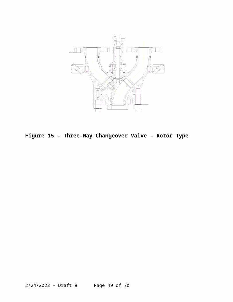
APPENDIX A – RUPTURE DISK INSTALLATION GUIDELINES
A.1. GeneralThe Appendix provides basic guidelines for the correct installation of rupture disks in a typical piping/pressure relief scheme. Due to the variety of styles and types of rupture disks commercially available, it would be impractical to discuss them all in this Appendix. Accordingly, this Appendix will only discuss typical industrial applications using more common rupture disks and rupture disk holders. Installation considerations for more specialized rupture disk products (sanitary/aseptic rupture disks, disks for high viscosity fluid environments, plastic extruder products, etc) should be acquired from rupture disk manufacturers. Should any information presented be in conflict with the specific installation instructions of any rupture disk manufacturer, the manufacturer’s installation instructions should take priority. Personnel involved in the installation and maintenance of rupture disks should be properly trained. When removing a rupture disk device from a pressure relief scheme, the user is reminded the device may be contaminated with toxic or hazardous process media. Appropriate care should be taken to prevent injuries.
A.2. Companion FlangesThe pipe flanges, into which a rupture disk is to be installed, are herein called the “companion flanges”. The companion flanges should be properly spaced and aligned to ensure the piping scheme does not apply its own unknown and unwanted piping stress or clamping forces to the device that may impact the performance of the rupture disk. Precision installation of rupture disks will both ensure accurate burst pressures and afford the longest possible service life of the rupture disk. Figure A.1 provides a typical configuration of companion flanges, gaskets and rupture disk assembly.
A.3 Gasket SelectionAlthough there are exceptions, rarely are gaskets used between the rupture disk and the rupture disk holder, the typical seal being affected metal-to-metal. The gaskets used for installing the rupture disk device in a piping scheme must be selected for process compatibility, but should also be selected so the force required to properly energize the gasket does not significantly exceed the torque specified by the rupture disk manufacturer’s installation instructions. Depending upon the type of disk in use, exceeding the manufacturer’s specified torque may dramatically change the burst pressure, crush the disk materials of construction, cause leakage, result in premature activation, and/or damage the rupture disk holder so proper performance of subsequent installations would be impossible without replacing the holder. If the gasket of choice is “spiral wound”, gaskets selected should be the “low stress” or “low energy” type to minimize the probability of disk inaccuracies and holder damage. Most rupture disk manufacturers encourage the use of high quality, non-asbestos, compressed fiber gaskets. However, other gaskets such as fiber filled and non-cold flowing fluoropolymer gaskets are also suitable. Clearly, the intent is to assure a positive system seal without overloading the rupture disk device. Typically, used gaskets should be replaced whenever the disk device is disassembled during field service.
A.4 Rupture Disk Holder ServiceabilityEnsure the condition of the rupture disk holder is clean, free from debris, not coated, plated, or plugged by process materials. Assure clean gasket surfaces on the outside of the holder. Since the “disk/holder interface” ensures proper rupture disk performance, holders should be cleaned with appropriate solvents and very fine emery cloth to assure the critical seating surface dimensions are not changed. Bead blasters (or equivalent) should never be used to clean a rupture disk holder. No modifications should be made to a rupture disk holder, except by its original manufacturer. Most manufacturers will evaluate holders for serviceability and, in some cases, can re-machine critical dimensions and return a holder to the user for continued service if it has been damaged through improper installation, excessively aggressive cleaning, and/or superficial corrosion. If the rupture disk device is of a type activated by knife blades installed in and
5/6/2023 – Draft 8 Page 49 of 58

integral to the outlet of the rupture disk holder, caution is directed to ensure the blades are maintained in strict compliance with the manufacturer’s guidance.
A.5 Rupture Disk Suitability for ApplicationEnsure the disk acquired for installation is in fact the correct disk for the application and that the disk is compatible with the selected rupture disk holder. Not uncommonly, plants have a wide variety of styles of rupture disks and associated rupture disk holders. Compatibility is crucial. A rupture disk installed in a holder not designed for that style of disk can create a hazardous application. Verify with the manufacturer’s installation instructions (or by contacting the manufacturer) that the disk intended for installation is compatible with the holder to be used.
A.6 Preparing the Rupture Disk For InstallationA rupture disk should not be removed from the manufacturer’s packaging until ready to be installed in the holder. Rupture disks should be handled carefully and only by the external rim of the disk and the rupture disk tag, as illustrated in Figure A.2. The surface of the pressure-sensitive element of the disk (commonly the “dome” or “crown”) should not be touched (see Figure A.3).
When the holder has been prepared to receive the new disk, the disk should be removed from the packaging. Prior to installation of the disk into the holder, the rupture disk should be very carefully inspected for damage. Any damage to the disk will affect the burst pressure and may create an unsafe installation and/or cause significantly reduced service life. A damaged disk should never be installed. Performance-influencing damage is usually quite visible. If any surface anomaly is visible from both sides of the disk, it should not be installed, regardless of how slight the damage may be. Depending upon the type or style of disk used, even a tiny amount of damage may result in an unsafe installation.
Personnel responsible for inspection and installation of rupture disks should be properly trained to avoid rejecting serviceable disks. For example, disks are occasionally heat treated and show, as a result, a discoloration that is not a criteria for rejection. Disks sometimes also show on their surface mill marks that typically appear to be fine parallel scratches on the surface of the disk and that are insufficient reason for disk rejection. Always consult with the manufacturer if unsure whether a disk is damaged and unsafe to install.
A.7 Installation of the Rupture Disk Into the Rupture Disk HolderWhen installing a rupture disk into the holder, there should be no more than one disk in the vicinity of the holder to eliminate the risk of the wrong disk being installed. With the inlet and outlet of the holder being separated, the disk should be carefully installed on the top of the inlet. The disk should be of the form, fit, and function to align itself properly on the inlet half of the holder. In some cases, special centering and locating features are supplied by the manufacturer. Commonly, special notches or offset locating pins assure proper alignment, centering, and directional orientation. On other types of disks and holders, the centering and alignment is characteristic of the compatible shape of the rim of the disk and its holder interface…such as an “angular” seating surface. Regardless of the particular design, the installation of the disk in the holder should be straight-forward, easy, and require no effort. If the fit is difficult, refer to the manufacturer’s installation instructions or contact the manufacturer. With the disk properly seated on the inlet, the outlet of the holder may be installed on top of the disk. Extreme care must be exercised to prevent damage to the disk while installing the outlet portion of the holder. The outlet should, likewise, easily align and center on the vent (downstream; atmospheric) side of the disk. Once the disk is installed between the inlet and outlet of the holder, a variety of mechanisms are provided by manufacturers to hold the rupture disk device together, prior to being installed in the piping scheme. Commonly, there are “side lugs” used for this purpose. In other designs, the assembly is properly torqued together with recessed cap screws. As always, follow the manufacturer’s installation instructions to properly retain the integrity of the rupture disk device and prevent damage to the disk; pay particular attention to directional orientation.
5/6/2023 – Draft 8 Page 50 of 58

A.8 Installation of the Rupture Disk Device Into a Piping/Pressure Relief SchemeEnsure the gasket surfaces of the companion flanges are clean and prepared for new gaskets. Once again, paying critical attention to proper direction orientation (see flow arrows on the disk and holder and installation instructions for installation direction as shown in Figure A.4), install the assembled rupture disk device and gaskets between the companion flanges and install the companion flange studs.
The rupture disk holder should be of the proper flange rating to effectively self-center between the studs. Proper performance of the rupture disk and longest service life is significantly improved by following the manufacturer’s torque requirements for the companion flange studs. Progressively tightening the studs in increasing one-fourth increments of the required torque load helps to equally distributed clamping force on the rupture disk holder, both assuring proper sealing and disk performance. Typically the torque to the studs should be applied following a “cross-torquing” pattern. Always ensure the installation instructions are followed to assure that proper torque is applied.
A.9 Rupture Disk MaintenanceRupture disk manufacturers provide instructions and guidelines for the proper installation and maintenance of the variety of rupture disk designs they offer. However, since rupture disk performance is unique to each disk type and the specific application environment into which it is installed, the maintenance routine and frequency of replacement cannot be generalized. Certainly, some disks are better suited for some applications than others. Service life (durability) is a function of both the disk design and the particular application conditions. Is the disk specified designed to be fully process compatible with corrosive conditions? Is it designed to be highly resistant to cyclic fatigue? Is the disk design suited for the maximum operating pressures to which it will be exposed? These and other associated questions can only be answered by a discussion about the disk style or type with complete consideration of the application.
In general, rupture disk manufacturers discourage the re-use of a disk anytime the clamping force at the disk-holder interface is relaxed/relieved since the performance of a reinstalled disk is unpredictable. Once the torque (clamping force) on a disk is removed, a reinstalled disk taking the same “set” as during initial installation is remote. Depending on the design, the disk may or may not be suitable for re-use once disassembled, if they have not been damaged in handling and disassembly. Always verify with the manufacturer if a particular disk design can be reinstalled. If a disk is installed in a pre-torqued holder, the rupture disk device may be removed from the piping scheme, carefully inspected, and returned to service if the disk isn’t pitted from corrosion, heavily plated or contaminated with process media, etc. If the disk appears in good condition, it may be re-used since the clamping force on the disk has not been disturbed in the pre-torqued rupture disk holder.
It is not uncommon for rupture disks to be damaged during handling and installation due to the reasonably fragile nature of rupture disks in general and specifically those disks designed for low pressure applications. Damaged disks should never be installed. Although damage suitable for disk rejection is, again, characteristic of a particular disk design, any damage evident on the dome or crown of a disk which is visible on both sides of the pressure-sensitive element (positive and negative dents or scratches) is justification for rejection since the precision and serviceability are probably compromised and will, most likely, result in premature, or nuisance activations. Superficial “scratches” are commonly “mill marks” caused by the rolling of the disk material to different thicknesses. Mill marks are inconsequential and do not impact disk performance.
Depending upon the disk type and manufacturing procedures, disks may be annealed or thermally stress relieved. This process may result in the superficial discoloration of the disk material which is rarely disqualifying. Should discoloration be undesirable for a particular application, the end user may request disks be vacuum annealed or heat treated in an inert environment such as argon.
If the user/installer sees any characteristic which is perceived as damage, the manufacturer should be contacted to verify serviceability or cause for rejection. Conveniently, digital photos of rupture disks may be sent to the manufacturer for responsive evaluation of suitability of service
5/6/2023 – Draft 8 Page 51 of 58

Often overlooked is the condition of the rupture disk holder. The holder should be maintained as recommended by the manufacturer. Usually the disk/holder interface has critical dimensions which will change the performance and precision of the rupture disk device if compromised. Rupture disk holders should not be cleaned by bead or sand blaster. Process plating should be carefully removed from the rupture disk holder using fine emery cloth to maintain the correct tolerances. Rupture disk holders may also be damaged or permanently “deflected” by excessive torque supplied by the pipe flanges and studs. Rupture disk manufacturers provide a recommended pipe flange torque to ensure adequate system sealing while concurrently preserving the serviceability of the holder. Issues related to pipe flange stud torque beyond that recommended in installation instructions should be directed to the disk manufacturer.
A properly installed rupture disk will provide the intended safety and pressure relief at the pressure and temperature specified by the user. Additionally, a properly installed rupture disk device will ensure the longest service life, best performance, and minimize the possibility of nuisance and fatigue activations caused by inattentive and improper installation.
5/6/2023 – Draft 8 Page 52 of 58

Figure A.1 – Typical Configuration of Companion Flanges, Gaskets and Rupture Disk Assembly
5/6/2023 – Draft 8 Page 53 of 58

Figure A.2 – Proper Handling of a Rupture Disk
Figure A.3 – Improper Handling of a Rupture Disk
5/6/2023 – Draft 8 Page 54 of 58

Figure A.4 – Proper Alignment of Rupture Disk indicated by Tag Arrows
APPENDIX B – INSTALLATION & MAINTENANCE OF PIN-ACTUATED NON-RECLOSING PRESSURE RELIEF DEVICESB.1 GeneralPin-Actuated non-reclosing pressure relief devices comprise two main components. The first component is the mechanism (piston or disc) that moves from the ‘closed’ to the ‘open’ position during the overpressure event. The second main component is the buckling pin that maintains the piston or disk in the closed position and that buckles in response to overpressure to activate the opening of the disk. To ensure the proper performance of such pin-actuated devices, the following Installation and maintenance requirements should be followed
B.2 Installation1. Check that the main actuating device and the buckling pin are provided by the same manufacturer.
These items function in combination with each other to provide the required pressure system protection. Check that the pins are certified for use in the mechanism by the Manufacturer.
2. Only use buckling pins that are traceable to the device manufacturer through the provision of an attached tag or equivalent marking. Do not install unmarked pins.
3. Ensure that the device is installed in the correct orientation. Follow the flow direction indicated on the device and verify using the Manufacturers installation instructions.
4. Ensure that the device is installed correctly to take account of gravity. Some pin-actuated pressure relief devices are sensitive to gravity because the weight of the mechanism contributes to the set pressure of the device. Follow the Manufacturer’s installation instructions and make sure that the device has been purchased to match the installation configuration (horizontal / vertical / oblique flow).
5/6/2023 – Draft 8 Page 55 of 58

5. Do not install buckling pins made for service in one device type into a different mechanism design. Buckling pins may be certified for use in a single mechanism, identified by the Manufacturer.
6. Install only buckling pins that are straight. Pins that are deformed will cause the pressure relief device to typically function at a reduced set pressure.
7. Some pin-actuated pressure relief devices are operated by differential pressure. Ensure that such devices are installed with a downstream pressure that is either monitored to maintain an appropriate pressure differential, or held at atmospheric pressure.
8. Follow the Manufacturer’s pin installation instructions and use special tools where recommended. Buckling pins are typically installed into a mechanism housing. Ensure that any bolts or screw threads are not overtightened, this can lead to pin failure during installation.
9. Where electrical sensors are fitted to the pin-actuated pressure relief device, ensure that the appropriate electrical design standards for the application are met.
10. Ensure that the installation is capable of containing recoil forces when the pin-actuated pressure relief device operates.
11. Pins shall not be installed while the pressurized system is operating. This can lead to premature operation of the pressure relief device and injury to the user.
12. Where a device is supplied with a fluid drain to prevent internal accumulation, this drain shall be discharged to an appropriate location.
B.3 Maintenance1. Pin-actuated pressure relief devices can be reset as a maintenance activity without complete removal of
the device. Ensure that the system is not pressurized at this time. Device reset requires the installation of a replacement buckling pin. Follow the Manufacturer’s instructions for removal of the used pin, reclosing of the mechanism and installation of the replacement part.
2. Never use any objects other than a buckling pin to hold the mechanism closed during service. Install only replacement buckling pins that are certified by the device Manufacturer for use in the mechanism to be reset.
3. Do not change the mechanism and pin combination, unless agreed to by the Manufacturer. Recertification of the device set pressure may be required.
4. When reclosing the device, there should be freedom of movement of the mechanism. Excessive force can cause damage to the mechanism and is an indication of a blockage in the flow path. In this case, the device flow path should either be inspected in place or the device should be removed from service to determine and remove the reason for the blockage.
5. When seals are replaced, install only seals supplied by the Manufacturer, and follow the Manufacturer’s seal replacement instructions.
6. Maintenance that requires disassembly of the pin-actuated pressure relief device shall be under the direction of the manufacturer. Improper reassembly may alter the device set pressure.
7. Buckling pins can be removed from the mechanism (when there is no pressure in the system) to check for freedom of movement, and then reinstalled. Follow the manufacturer’s instructions. Do not reinstall a damaged pin, this will result in premature opening of the device.
8. Where components of devices require special lubrication or grease, the manufacturer’s recommended lubrication shall be used.
5/6/2023 – Draft 8 Page 56 of 58
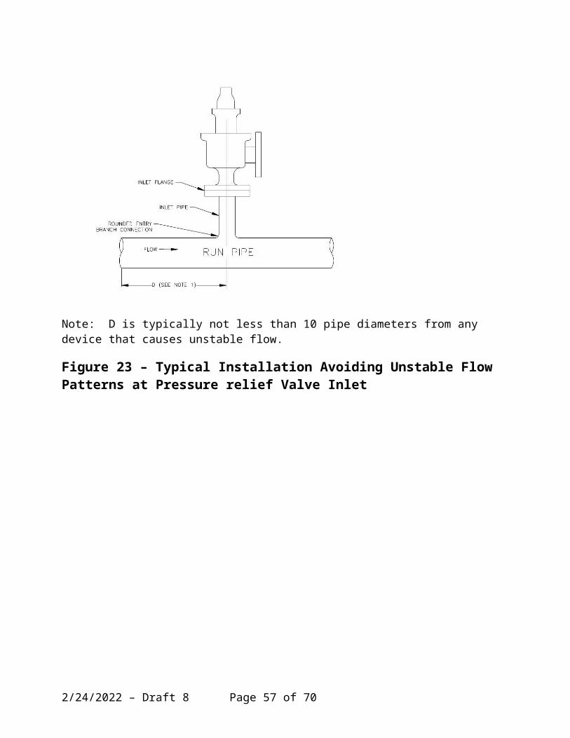
APPENDIX C – TECHNICAL INQUIRIES
5/6/2023 – Draft 8 Page 57 of 58
Bibliography
[1] N. E. Sylvander and D. L. Katz, The Design and Construction of Pressure Relieving Systems, Engineering Research Bulletin No. 31, Engineering Research Institute, University of Michigan Press, April 1948
[2] E. Jenett, Components of Pressure Relieving Systems, Chemical Engineering, Volume 70, August 1963, pp 151 - 158.
5/6/2023 – Draft 8 Page 58 of 58