sk 2000 - assets.sennheiser.com · the sk 2000 bodypack transmitter the sk 2000 bodypack...
TRANSCRIPT
SK 2000
Instruction manual
1
Contents
Important safety instructions .......................................................................... 2
The SK 2000 bodypack transmitter ................................................................ 3
Areas of application ........................................................................................ 3
The frequency bank system .......................................................................... 4
Delivery includes .................................................................................................. 5
Product overview ................................................................................................. 6
Overview of the SK 2000 bodypack transmitter ....................................... 6
Overview of the displays ................................................................................ 7
Putting the bodypack transmitter into operation ....................................... 8
Inserting the batteries/accupack ................................................................. 8
Charging the accupack .................................................................................... 8
Connecting the microphone cable/instrument cable ............................... 9
Attaching the bodypack transmitter to clothing ................................... 10
Using the bodypack transmitter ................................................................... 11
Switching the bodypack transmitter on/off ........................................... 11
Deactivating the lock mode temporarily ................................................. 12
Muting the audio signal or deactivating the RF signal ......................... 13
Selecting a standard display ...................................................................... 15
Using the operating menu ............................................................................. 16
The buttons .................................................................................................... 16
Overview of the operating menu ............................................................... 16
Working with the operating menu ........................................................... 18
Synchronizing the bodypack transmitter with a receiver ...................... 20
Synchronizing the bodypack transmitter with the receiver –
individual operation ..................................................................................... 20
Synchronizing bodypack transmitters with receivers –
multi-channel operation .............................................................................. 20
Cleaning the bodypack transmitter ............................................................. 21
If a problem occurs ... ....................................................................................... 21
Specifications .................................................................................................... 23
For further information, visit the SK 2000 product page on
our website at www.sennheiser.com.

2
Important safety instructions
Important safety instructions
• Read this instruction manual.
• Keep this instruction manual. Always include this instruction manual
when passing the product on to third parties.
• Heed all warnings and follow all instructions.
• Use only a cloth for cleaning the product.
• Do not place the product near any heat sources such as radiators, stoves,
or other devices (including amplifiers) that produce heat.
• Only use attachments/accessories specified by Sennheiser.
• Refer all servicing to qualified service personnel.
Servicing is required if the product has been damaged in any way, liquid
has been spilled, objects have fallen inside, the product has been
exposed to rain or moisture, does not operate properly or has been
dropped.
• WARNING: To reduce the risk of short circuits, do not use the product
near water and do not expose it to rain or moisture.
Intended use
Intended use of the SK 2000 bodypack transmitter includes:
• having read this instruction manual, especially the chapter “Important
safety instructions”,
• using the product within the operating conditions and limitations
described in this instruction manual.
“Improper use” means using the product other than as described in these
instructions, or under operating conditions which differ from those
described herein.

3
The SK 2000 bodypack transmitter
The SK 2000 bodypack transmitter
This bodypack transmitter is part of the 2000 series. With this series,
Sennheiser offers high-quality state-of-the-art RF transmission systems
with a high level of operational reliability and ease of use. Transmitters
and receivers permit wireless transmission with studio-quality sound.
Features of the 2000 series:
• Optimized PLL synthesizer and microprocessor technology
• HDX noise reduction system
• Pilot tone squelch control
• True diversity technology
• Switching bandwidth of up to 75 MHz
• Increased immunity to intermodulation and interferences in multi-
channel operation
Areas of application
The bodypack transmitter can be combined with the EM 2000 or EM 2050
rack-mount receiver. The receivers are available in the same UHF
frequency ranges and are equipped with the same frequency bank system
with factory-preset frequencies. An advantage of the factory-preset
frequencies is that:
• a transmission system is ready for immediate use after switch-on,
• several transmission systems can be operated simultaneously on the
preset frequencies without causing intermodulation interference.
Transmitter Optional accessories Receivers
SK 2000 • Clip-on microphones:
MKE 1, ME 102,
ME 104, ME 105*
EM 2000 receiver
EM 2050 twin receiver
• Headmics:
HSP 2, HSP 4*
• Instrument cable:
CI 1-4*
* each fitted with a 3-pin special audio connector
543.200B.Ch: 20.64PEAK
MUTE
EQ:
+ 12dBP
-10
040
30
20
10
-20
-30
-40
AFRF
MHz
True Diversity Receiver EM 2000 **2000**
SKM2000
543.200**2000** **2000**B.Ch: 20.64PEAK
MUTE
EQ:
+ 12dBP
-10
040
30
20
10
-20
-30
-40
AFRF
MHz 543.200B.Ch: 20.64PEAK
MUTE
EQ:
+ 12dBP
-10
040
30
20
10
-20
-30
-40
AFRF
MHz
True Diversity Receiver EM 2050
SKM2000 SKM2000
4
The SK 2000 bodypack transmitter
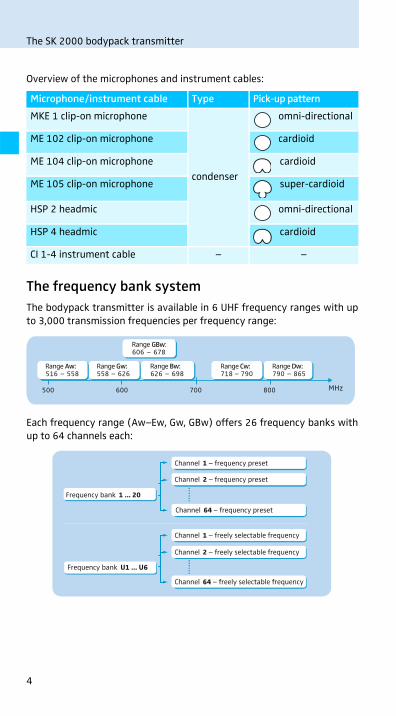
Overview of the microphones and instrument cables:
The frequency bank system
The bodypack transmitter is available in 6 UHF frequency ranges with up
to 3,000 transmission frequencies per frequency range:
Each frequency range (Aw–Ew, Gw, GBw) offers 26 frequency banks with
up to 64 channels each:
Microphone/instrument cable Type Pick-up pattern
MKE 1 clip-on microphone
condenser
omni-directional
ME 102 clip-on microphone cardioid
ME 104 clip-on microphone cardioid
ME 105 clip-on microphone super-cardioid
HSP 2 headmic omni-directional
HSP 4 headmic cardioid
CI 1-4 instrument cable – –
500 600 700 800
Range Gw:558 – 626
Range Bw:626 – 698
Range Cw:718 – 790
Range Dw:790 – 865516 – 558
Range Aw:
GBw:606 – 678Range
Frequency bank 1 ... 20
Frequency bank U1 ... U6
Channel 64 – frequency preset
Channel 1 – frequency preset
Channel 2 – frequency preset
Channel 64 – freely selectable frequency
Channel 1 – freely selectable frequency
Channel 2 – freely selectable frequency

5
Delivery includes
Each of the channels in the frequency banks “1” to “20” has been factory-
preset to a fixed frequency (frequency preset). The factory-preset
frequencies within one frequency bank are intermodulation-free. These
frequencies cannot be changed.
For an overview of the frequency presets, please refer to the supplied
frequency information sheet. Updated versions of the frequency informa-
tion sheet can be downloaded from the corresponding product page on our
website at www.sennheiser.com.
The frequency banks “U1” to “U6” allow you to freely select and store
transmission frequencies. It might be that these transmission frequencies
are not intermodulation-free.
Delivery includes
The packaging contains the following items:
1 SK 2000 bodypack transmitter
2 AA size batteries, 1.5 V
1 instruction manual
1 frequency information sheet
1 supplement “Framework requirements and restrictions on the use of
radio microphones”

6
Product overview
Product overview
Overview of the SK 2000 bodypack transmitter
� Microphone/instrument input
(MIC/LINE), 3-pole special audio
socket, lockable
� MUTE switch
� Antenna
� Operation and battery status
indicator, red LED:
lit = ON
flashing = LOW BATT
� Audio overmodulation indicator,
yellow LED:
lit = AF PEAK
� Charging contacts
� SET button
UP/DOWN button �/� Battery compartment
� Battery compartment cover
(metal)
� Battery compartment catches
Infra-red interface
� ON/OFF button
(serves as the ESC (cancel) key in
the operating menu)
� Display panel, backlit in orange
�
�
�
��
�
�
�
�
�
�
��
7
Product overview
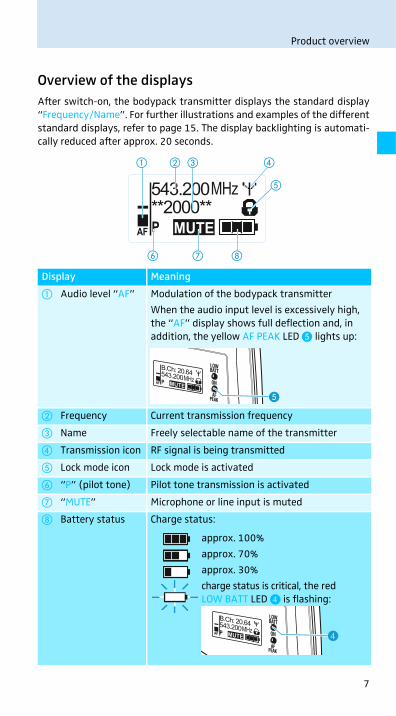
Overview of the displays
After switch-on, the bodypack transmitter displays the standard display
“Frequency/Name”. For further illustrations and examples of the different
standard displays, refer to page 15. The display backlighting is automati-
cally reduced after approx. 20 seconds.
Display Meaning
� Audio level “AF” Modulation of the bodypack transmitter
When the audio input level is excessively high,
the “AF” display shows full deflection and, in
addition, the yellow AF PEAK LED � lights up:
� Frequency Current transmission frequency
� Name Freely selectable name of the transmitter
� Transmission icon RF signal is being transmitted
� Lock mode icon Lock mode is activated
� “P” (pilot tone) Pilot tone transmission is activated
� “MUTE” Microphone or line input is muted
� Battery status Charge status:
MHz543.200**2000**
MUTEPAF
� ��
�
�
���
�
approx. 100%
approx. 70%
approx. 30%
charge status is critical, the red
LOW BATT LED � is flashing:
�

8
Putting the bodypack transmitter into operation
Putting the bodypack transmitter into
operation
Inserting the batteries/accupack
For powering the bodypack transmitter, you can either use two 1.5 V AA
size batteries or the rechargeable Sennheiser BA 2015 accupack or the
DC 2 power adapter (accessories, visit www.sennheiser.com).
� Open the battery compartment by pushing the two catches � in the
direction of the arrows and open the cover �.
� Insert the two batteries or the accupack as shown above. Please
observe correct polarity when inserting the batteries/accupack.
� Close the battery compartment.
The battery compartment cover � locks into place with an audible
click.
Charging the accupack
To charge the BA 2015 accupack (accessory, visit www.sennheiser.com)
installed in the bodypack transmitter:
� Insert the bodypack transmitter into the L 2015 charger (accessory,
visit www.sennheiser.com).
The L 2015 charger can only charge the combination BA 2015
accupack/bodypack transmitter. Standard batteries (primary
cells) or individual rechargeable battery cells cannot be charged.
� �
�
�
�

9
Putting the bodypack transmitter into operation
Connecting the microphone cable/instrument cable
The audio input is designed for the connection of both condenser micro-
phones and instruments (e.g. guitars). DC powering of the condenser
microphones is via the MIC/LINE socket � (3-pole special audio socket).
� Use one of the recommended Sennheiser microphones or the CI 1-4
instrument cable (see page 3).
� Connect the 3-pin special audio connector � from the Sennheiser
microphone or instrument cable to the MIC/LINE socket �.
� Lock the 3-pin special audio connector by screwing down the coupling
ring �.
� Via the operating menu (“Sensitivity” menu item), adjust the sensi-
tivity of the microphone/line input.
�
�
�
10
Putting the bodypack transmitter into operation
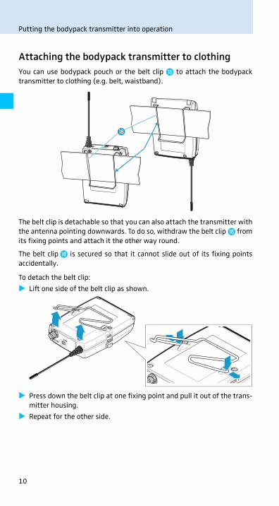
Attaching the bodypack transmitter to clothing
You can use bodypack pouch or the belt clip � to attach the bodypack
transmitter to clothing (e.g. belt, waistband).
The belt clip is detachable so that you can also attach the transmitter with
the antenna pointing downwards. To do so, withdraw the belt clip � from
its fixing points and attach it the other way round.
The belt clip � is secured so that it cannot slide out of its fixing points
accidentally.
To detach the belt clip:
� Lift one side of the belt clip as shown.
� Press down the belt clip at one fixing point and pull it out of the trans-
mitter housing.
� Repeat for the other side.
�
11
Using the bodypack transmitter
Using the bodypack transmitter
To establish a transmission link, proceed as follows:
1. Switch the bodypack transmitter on (see next section).
2. Switch the receiver on (see the instruction manual of the receiver).
The transmission link is established and the display backlighting of the
receiver changes from red to orange.
If you cannot establish a transmission link between transmitter and
receiver, read the chapter “Synchronizing the bodypack transmitter with a
receiver” on page 20.
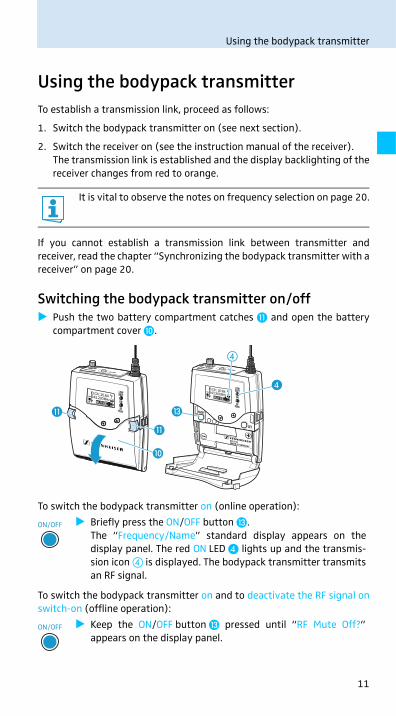
Switching the bodypack transmitter on/off
� Push the two battery compartment catches � and open the battery
compartment cover �.
To switch the bodypack transmitter on (online operation):
To switch the bodypack transmitter on and to deactivate the RF signal on
switch-on (offline operation):
It is vital to observe the notes on frequency selection on page 20.
� Briefly press the ON/OFF button �.
The “Frequency/Name” standard display appears on the
display panel. The red ON LED � lights up and the transmis-
sion icon � is displayed. The bodypack transmitter transmits
an RF signal.
� Keep the ON/OFF button � pressed until “RF Mute Off?”
appears on the display panel.
�
�
�
�
�
�
ON/OFF
ON/OFF
12
Using the bodypack transmitter
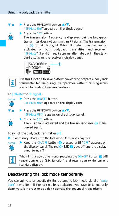
To activate the RF signal:
To switch the bodypack transmitter off:
� If necessary, deactivate the lock mode (see next chapter).
Deactivating the lock mode temporarily
You can activate or deactivate the automatic lock mode via the “Auto
Lock” menu item. If the lock mode is activated, you have to temporarily
deactivate it in order to be able to operate the bodypack transmitter:
� Press the UP/DOWN button �/�.
“RF Mute On?” appears on the display panel.
� Press the SET button.
The transmission frequency is displayed but the bodypack
transmitter does not transmit an RF signal. The transmission
icon � is not displayed. When the pilot tone function is
activated on both bodypack transmitter and receiver,
“RF Mute” (backlit in red) appears alternately with the stan-
dard display on the receiver’s display panel.
Use this function to save battery power or to prepare a bodypack
transmitter for use during live operation without causing inter-
ference to existing transmission links.
� Press the ON/OFF button.
“RF Mute On?” appears on the display panel.
� Press the UP/DOWN button �/�.
“RF Mute Off?” appears on the display panel.
� Press the SET button.
The RF signal is activated and the transmission icon � is dis-
played again.
� Keep the ON/OFF button � pressed until “OFF” appears on
the display panel. The red ON LED � goes off and the display
panel turns off.
When in the operating menu, pressing the ON/OFF button � will
cancel your entry (ESC function) and return you to the current
standard display.
SET
MHz543.200**2000**
MUTEPAF
�
ON/OFF
SET
ON/OFF

13
Using the bodypack transmitter
The lock mode icon � flashes prior to the lock mode being activated again.
Muting the audio signal or deactivating the RF signal
The MUTE switch � allows you to mute the audio signal or to deactivate
the RF signal. Via the “Mute Mode” menu item, you can set the desired
function of the MUTE switch �.
� From the “Mute Mode” menu item, select the desired setting.
� Exit the operating menu.
� Slide the MUTE switch � to the left, to the position MUTE.
The bodypack transmitter reacts as indicated in the table.
� Press the SET button or the ON/OFF button.
“Locked” appears on the display panel.
� Press the UP/DOWN button �/�.
“Unlock?” appears on the display panel.
� Press the SET button.
The lock mode is temporarily deactivated.
– When you are in the operating menu, the lock mode
remains deactivated until you exit the operating menu.
– When one of the standard displays is shown, the lock mode
is automatically activated after 10 seconds.
Setting Slide the MUTE switch � ... Function
“AF On/Off” ... to the left (position MUTE) Mutes the audio signal
... to the right Unmutes the audio signal
“RF On/Off” ... to the left (position MUTE) Deactivates the RF signal
(offline operation)
... to the right Activates the RF signal
(online operation)
“Disabled” No function
SET ON/OFF
SET
543.200B.Ch: 20.64PEAK
MUTEEQ:
+ 12dB
-10040
302010
-20-30-40AFRF
MHz **2000**
SKM2000P
�
�
14
Using the bodypack transmitter
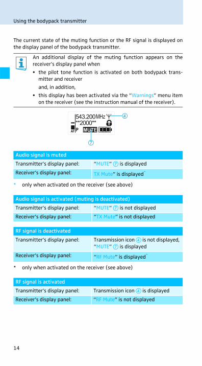
The current state of the muting function or the RF signal is displayed on
the display panel of the bodypack transmitter.
An additional display of the muting function appears on the
receiver’s display panel when
• the pilot tone function is activated on both bodypack trans-
mitter and receiver
and, in addition,
• this display has been activated via the “Warnings” menu item
on the receiver (see the instruction manual of the receiver).
Audio signal is muted
Transmitter’s display panel: “MUTE” � is displayed
Receiver’s display panel: TX Mute” is displayed*
* only when activated on the receiver (see above)
Audio signal is activated (muting is deactivated)
Transmitter’s display panel: “MUTE” � is not displayed
Receiver’s display panel: “TX Mute” is not displayed
RF signal is deactivated
Transmitter’s display panel: Transmission icon � is not displayed,
“MUTE” � is displayed
Receiver’s display panel: “RF Mute” is displayed*
* only when activated on the receiver (see above)
RF signal is activated
Transmitter’s display panel: Transmission icon � is displayed
Receiver’s display panel: “RF Mute” is not displayed
MHz543.200**2000**
MUTEPAF
�
�

15
Using the bodypack transmitter
Selecting a standard display
You can also deactivate the RF signal on switch-on. For more infor-
mation, refer to the chapter “Switching the bodypack transmitter
on/off” on page 11.
Using the ON/OFF button, you can also activate/deactivate the RF
signal during operation. To do so, briefly press the ON/OFF button
and proceed as described on page 12.
� Press the UP/DOWN button �/� to select a standard
display:
Contents of the display Selectable standard display
“Frequency/Name”
“Channel/Frequency”
“Name/Channel”
**2000** MHz543.200
MUTEPAF
MHz543.200B.Ch: 20.64
MUTEPAF
B.Ch: 20.64MUTEPAF
**2000**
16
Using the operating menu
Using the operating menu
The buttons
Overview of the operating menu
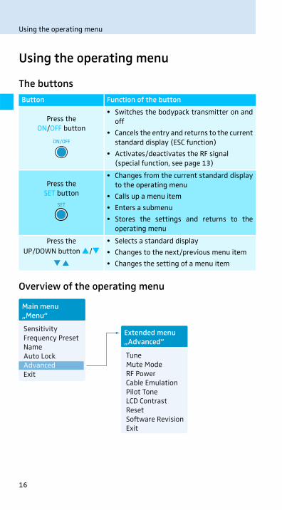
Button Function of the button
Press the
ON/OFF button
• Switches the bodypack transmitter on and
off
• Cancels the entry and returns to the current
standard display (ESC function)
• Activates/deactivates the RF signal
(special function, see page 13)
Press the
SET button
• Changes from the current standard display
to the operating menu
• Calls up a menu item
• Enters a submenu
• Stores the settings and returns to the
operating menu
Press the
UP/DOWN button �/�• Selects a standard display
• Changes to the next/previous menu item
• Changes the setting of a menu item
ON/OFF
SET
Main menu„Menu”
Sensitivity Frequency PresetNameAuto LockAdvanced Exit
TuneMute ModeRF PowerCable EmulationPilot Tone LCD Contrast ResetSoftware RevisionExit
Extended menu„Advanced”
17
Using the operating menu
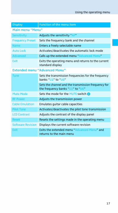
Display Function of the menu item
Main menu “Menu”
Sensitivity Adjusts the sensitivity “AF”
Frequency Preset Sets the frequency bank and the channel
Name Enters a freely selectable name
Auto Lock Activates/deactivates the automatic lock mode
Advanced Calls up the extended menu “Advanced Menu”
Exit Exits the operating menu and returns to the current
standard display
Extended menu “Advanced Menu”
Tune Sets the transmission frequencies for the frequency
banks “U1” to “U6”
Sets the channel and the transmission frequency for
the frequency banks “U1” to “U6”
Mute Mode Sets the mode for the MUTE switch �
RF Power Adjusts the transmission power
Cable Emulation Emulates guitar cable capacities
Pilot Tone Activates/deactivates the pilot tone transmission
LCD Contrast Adjusts the contrast of the display panel
Reset Resets the settings made in the operating menu
Software Revision Displays the current software revision
Exit Exits the extended menu “Advanced Menu” and
returns to the main menu

18
Using the operating menu
Working with the operating menu
By way of example of the “Sensitivity” menu, this section describes how to
use the operating menu.
Changing from a standard display to the operating menu
Selecting a menu item
Changing and storing settings
If the lock mode is activated, you have to deactivate it in order to
be able to work with the operating menu (see page 12).
� Press the SET button.
The current standard display is replaced by the main menu.
The last called up menu item is displayed.
� Press the UP/DOWN button �/� to change to the “Sensi-
tivity” menu item.
The current setting of the selected menu item is displayed:
� Press the SET button to call up the menu item.
� Press the UP/DOWN button �/� to adjust the input sensi-
tivity.
� Press the SET button to store the setting.
SET
MenuSensitivity
–12 dB
Menu
–12 dBSens i t i v i t y – 12 dB
Sens i t i v i t y–36 dB
Sens i t i v i t y
“Stored”
Call up “Sensitivity”
Select the desired setting
Store the setting
SET
SET

19
Using the operating menu
Canceling an entry
To subsequently return to the last edited menu item:
Exiting a menu item
To directly return to the current standard display:
� Press the ON/OFF button to cancel the entry.
The current standard display appears on the display panel.
� Press the SET button repeatedly until the last edited menu
item appears.
� Change to the “Exit” menu item.
� Confirm your selection.
You return to the next higher menu level or you exit the oper-
ating menu and return to the current standard display.
� Press the ON/OFF button.
ON/OFF
SET
MenuExit
SET
ON/OFF

20
Synchronizing the bodypack transmitter with a receiver
Synchronizing the bodypack transmitter
with a receiver
When synchronizing the bodypack transmitter with a receiver, please
observe the following:
Synchronizing the bodypack transmitter with the
receiver – individual operation
Upon delivery, the bodypack transmitter and the receiver are synchro-
nized with each other. However, if you cannot establish a transmission link
between bodypack transmitter and receiver, you have to synchronize the
channels of the devices.
For information on automatic synchronization of the bodypack trans-
mitter with the receiver (individual operation), refer to the instruction
manual of the receiver. This information is marked with the icon.
Alternatively, you can set the channel on the bodypack transmitter
manually:
� Make sure that you set the bodypack transmitter to the same
frequency bank and the same channel as the receiver.
If you still cannot establish a transmission link, refer to the chapter “If a
problem occurs ...” on page 21.
Synchronizing bodypack transmitters with
receivers – multi-channel operation
Combined with 2000 series receivers, 2000 series bodypack transmitters
can form transmission links that can be used in multi-channel systems.
For information on automatic synchronization of bodypack transmitters
with receivers (multi-channel operation), refer to the instruction manual
of your receiver.
For more information on multi-channel operation, visit the SK 2000
product at www.sennheiser.com.
� Only use a transmitter and a receiver from the same frequency
range (see the type plates on the transmitter and the
receiver).
� Make sure that the desired frequencies are listed in the
enclosed frequency information sheet.
� Make sure that the desired frequencies are approved and legal
in your country and, if necessary, apply for an operating
license.
21
Cleaning the bodypack transmitter
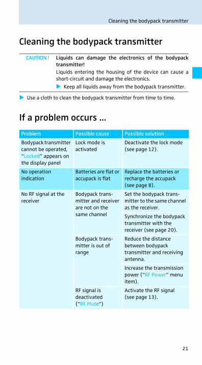
Cleaning the bodypack transmitter
� Use a cloth to clean the bodypack transmitter from time to time.
If a problem occurs ...
CAUTION ! Liquids can damage the electronics of the bodypack
transmitter!
Liquids entering the housing of the device can cause a
short-circuit and damage the electronics.
� Keep all liquids away from the bodypack transmitter.
Problem Possible cause Possible solution
Bodypack transmitter
cannot be operated,
“Locked” appears on
the display panel
Lock mode is
activated
Deactivate the lock mode
(see page 12).
No operation
indication
Batteries are flat or
accupack is flat
Replace the batteries or
recharge the accupack
(see page 8).
No RF signal at the
receiver
Bodypack trans-
mitter and receiver
are not on the
same channel
Set the bodypack trans-
mitter to the same channel
as the receiver.
Synchronize the bodypack
transmitter with the
receiver (see page 20).
Bodypack trans-
mitter is out of
range
Reduce the distance
between bodypack
transmitter and receiving
antenna.
Increase the transmission
power (“RF Power” menu
item).
RF signal is
deactivated
(“RF Mute“)
Activate the RF signal
(see page 13).

22
If a problem occurs ...
If a problem occurs that is not listed in the above table or if the problem
cannot be solved with the proposed solutions, please contact your local
Sennheiser partner for assistance.
To find a Sennheiser partner in your country, search at
www.sennheiser.com under “Service & Support”.
RF signal available,
no audio signal,
“MUTE” appears on
the display panel
Bodypack trans-
mitter is muted
(MUTE)
Cancel the muting
(see page 13).
Receiver’s squelch
threshold is
adjusted too high
Reduce the squelch
threshold setting on
the receiver.
Bodypack trans-
mitter doesn’t
transmit a pilot
tone
Activate or deactivate the
pilot tone transmission
(“Pilot Tone” menu item).
Audio signal has a
high level of back-
ground noise or is
distorted
Bodypack trans-
mitter’s sensitivity
is adjusted too
low/too high
Adjust the input
sensitivity (“Sensitivity”
menu item).
Problem Possible cause Possible solution

23
Specifications
Specifications
RF characteristics
AF characteristics
Modulation wideband FM
Frequency ranges 516–558, 558–626, 626–698,
718–790, 790–865, 606–678 MHz
(Aw to Dw, Gw, GBw, see page 4)
Transmission frequencies up to 3,000 frequencies,
tuneable in steps of 25 kHz
20 frequency banks, each with up
to 64 factory-preset channels
6 frequency banks, each with up
to 64 user programmable channels
Switching bandwidth up to 75 MHz
Nominal/peak deviation ±24 kHz/±48 kHz
Frequency stability ±15 ppm
RF output power at 50 switchable:
typ. 10 mW (Low)
typ. 30 mW (Standard)
typ. 50 mW (High)
Pilot tone squelch can be switched off
Compander system Sennheiser HDX
AF frequency response microphone: 80–18,000 Hz
line: 25–18,000 Hz
Signal-to-noise ratio
(1 mV, peak deviation)
120 dBA
THD 0.9 %
Max. input voltage
(microphone/line)
3 Vrms
Input impedance microphone: 40 k unbalanced
line: 1 M
Adjustment range of input
sensitivity
60 dB,
adjustable in 3-dB steps

24
Specifications
Overall device
In compliance with
Approved by
Connector assignment
Temperature range – 10°C to + 55°C
Power supply 2 AA size batteries, 1.5 V
or BA 2015 accupack
Nominal voltage 2.4 V
Power consumption:
• at nominal voltage
• with switched-off
transmitter
typ. 185 mA (30 mW)
25 μA
Operating time typ. 8 hrs
Dimensions approx. 82 mm x 64 mm x 24 mm
Weight (incl. batteries) approx. 160 g
Europe: EMC EN 301489-1/-9
Radio EN 300422-1/-2
Safety EN 60065
EN 62311 (SAR)
Canada: Industry Canada RSS-123
IC: 2099A-SK2000
limited to 698 MHz
USA: FCC-Part 74
FCC-ID: DMOSK2000
limited to 698 MHz
3-pin special audio connector
Pin 1: AF and 5.2 V AB-powering; 8.2 k internal
resistance, optimized for Sennheiser
pre-polarized condenser microphones
Pin 2: 5.2 V for guitar or ground
Pin 3 and thread: ground
1
3
1
2 32

Sennheiser electronic GmbH & Co. KG
Am Labor 1, 30900 W edemark, Germany www.sennheiser.com
Publ. 12/16, 549128