sk-net™ license number -...
TRANSCRIPT


Copyright© 2014SOUNDCRAFT, INC.
SK-NET™ License Number
ADS Serial Number
ADS Validation Code
If you purchased SK-NET-MLD-CSx, enter these numbers during installation of Advantage Database Server, prior to
installing SK-NET™ on Client Server Workstations.
If you purchased SK-NET-MLD, enter this license number (without the dashes) in SK-NET™,
under HELP/UPGRADE SYSTEM, to activate MLD features.
DO NOT LOSE THIS INFORMATION.Make a copy of this page and keep it in a secure
location for future reference.

SK-NET™Operating & Installation Guide
Contents
1. INTRODUCTION ..................................................................... 11.1 What is SK-NET™? .................................................................. 11.2 SK-NET™ Versions................................................................... 11.3 Computer System Requirements .............................................. 11.4 How is SK-NET™ Organized? .................................................. 2
2. GETTING STARTED ................................................................. 22.1 Site Plan ................................................................................. 22.2 Connecting Panels and/or 28SA Plus Card Readers to the Computer .. 32.3 Installing SK-NET™ on your Computer or Network................... 4 Single Workstation Installation (Basic Version) ......................... 4 Multiple Locations/Connection Groups .................................... 5 Activating SK-NET-MLD Software ............................................. 5
Email ............................................................................... 6 Phone .............................................................................. 7 FAX .................................................................................. 8 Multi Workstation Installation (Client/Server): .................... 9
3. QUICK START GUIDE.............................................................. 103.1 Starting SK-NET™ ................................................................. 103.2 Finding the Readers .............................................................. 113.3 Adding Multiple TCP/IP Connections to the Same Location .... 123.4 Naming the Readers ............................................................. 133.5 Setting a Latch Time for a Connection Group ........................ 143.6 Setting Solid State Relay Operation (NOVA.16) .................... 153.7 Enrolling Cards into your System ........................................... 153.8 Testing the System ................................................................ 17
4. CUSTOMIZE YOUR SYSTEM .................................................. 184.1 Creating Additional Locations .............................................. 18 (MLD or Client-Server versions only) ..................................... 184.2 Time Zones ........................................................................... 194.3 Editing a Location Time Zone ................................................ 194.4 Delaying the Start or End Time for the Half Hour Blocks ........ 204.5 Limiting the Dates a Time Zone is Active ............................... 214.6 Antipassback ........................................................................ 224.7 Selecting Antipassback for a Time Zone................................. 224.8 Timed Antipassback .............................................................. 234.9 Real Antipassback (RAPB) ...................................................... 244.10 Real Antipassback Forgive ..................................................... 254.11 Unscheduled RAPB Forgive ................................................... 264.12 Editing a Time Zone for a Single Reader ................................ 274.13 Access Groups ...................................................................... 284.14 Creating an Access Group .................................................... 284.15 Changing a Reader’s Time Zone in an Access Group ............. 294.16 Changing the Reader Icons ................................................... 304.17 Door Schedules .................................................................... 304.18 Programming a Door Schedule ............................................. 31 Location Door Schedule (All readers): .................................... 31 Single Door Schedule ........................................................... 32

4.19 Holidays ............................................................................... 324.20 Programming a Holiday ........................................................ 32 Location Holidays: ................................................................ 324.21 Changing the Latch Timer for a Single Reader ....................... 334.22 Using the SecuRelay™ ........................................................... 344.23 Date and Time ...................................................................... 354.24 Setting the Time and Date .................................................... 354.25 Configuring or Overriding U.S. Daylight Saving Time Feature .. 354.26 IN and OUT Readers ............................................................. 384.27 Programming an “IN” or an “OUT” Reader ............................ 384.28 Reader Groups ..................................................................... 394.29 Creating a Reader Group ...................................................... 394.30 Door Controls ....................................................................... 404.31 Using Door Controls ............................................................. 404.32 Inputs ................................................................................... 414.33 Defining an Input ................................................................. 424.34 Outputs ................................................................................ 434.35 Programming Custom Wiegand Data Formats ....................... 524.36 Adding New Readers to the System ....................................... 534.37 Adding a Facility Code .......................................................... 54
5. MANAGING USERS .............................................................. 565.1 Entering Cardholder Information ........................................... 565.2 Adding a New Card Number ................................................ 575.3 Deleting a User .................................................................... 575.4 Changing the Names of User Data Fields .............................. 575.5 Sorting Cardholders in the User List ...................................... 585.6 Filtering Users ...................................................................... 585.7 Limited Use Cards ................................................................ 595.8 Programming Limited Use Cards ........................................... 595.9 Integrated Badge Printing ..................................................... 61
6. MANAGING TRANSACTIONS ............................................... 676.1 Changing Transaction View ................................................... 676.2 Filtering Transactions ............................................................ 686.3 Viewing Cardholder Photos When They Badge ........................ 686.4 Archiving Older Transactions ................................................. 696.5 Viewing Archived Transactions .............................................. 706.6 Excluding Transaction Types .................................................. 706.7 Excluding Transaction Types for All Readers ........................... 706.8 Excluding Transaction Types for One Reader .......................... 71
7. REPORTS .............................................................................. 727.1 Transaction Reports ............................................................... 727.2 User Information Reports ...................................................... 737.3 Print a System Report (List of readers in a location) ................ 747.4 Printing a List of Users in an Access Group Report ................. 75
8. SECURITY .............................................................................. 778.1 Changing an SK-NET™ Operator Password ........................... 778.2 Assigning Operator Levels .................................................... 788.3 System Activity Log ............................................................... 798.4 Password Protection .............................................................. 79
9. DIAGNOSTICS ...................................................................... 819.1 Communicating with a Location ............................................. 819.2 Network Messages ............................................................... 81

8119 3321876
9.3 Self Testing from SK-NET™ .................................................... 829.4 Backup Battery Monitoring .................................................... 82
10. TROUBLESHOOTING ............................................................ 8510.1 RS232/RS485 or LAN (TCP/IP) Communications Setup: .......... 8510.2 RS232 Communications Failure: ........................................... 8510.3 Login Failure (RS485) ............................................................ 8610.4 Data Errors: .......................................................................... 8810.5 Card Send Failures: .............................................................. 8810.6 Replacing a 28SA+ or Control Panel ..................................... 8810.7 Power Reset .......................................................................... 8910.8 NET-CONV-P (RS232to RS485) Connection Failure ................ 9010.9 New Transactions are Not Appearing on the Transaction Screen .... 9110.10 Cards Show Void after Creating a New Access Group ............ 9110.11 Invalid Facility Code When Using New Cards ........................ 92
11. Remote Eyes® Video Integration ......................................... 9311.1 The Remote Eyes® DVR ......................................................... 9311.2 SK-NET™ Set-up for Remote Eyes® ................................................................. 93
11.3 Reviewing a Video Clip ......................................................... 9412. HIKVision Video Integration ............................................... 95
12.1 SK-NET™ Setup for Hikvision ................................................. 9512.2 Playing Back Video Clips ....................................................... 9612.3 Show Clip ............................................................................. 9712.4 Show All Clips from Selected Transaction............................... 9812.5 Download Clip ..................................................................... 9812.6 Show User Picture (Live vs. Stored Image) .............................. 98
13.0 LOCKDOWN AND DOOR STATUS FEATURES .................... 10113.1 Securing Your Facility ............................................................ 10113.2 Door Status ........................................................................ 10213.3 Lockdown Levels ................................................................. 10313.4 Lockdown Override Cards ................................................... 10413.5 Configuring and Enabling the Lockdown Feature ................. 10513.6 Configuring and Enabling the Door Status Feature .............. 10613.7 Using the Lockdown Feature ............................................... 10713.8 Canceling the Lockdown ..................................................... 10813.9 Mantrap Entrance ............................................................... 109
Appendix A - SK-NET™ FEATURES ........................................... 111Appendix B - WORKING IN WINDOWS ................................... 114Appendix C - USING SECURA KEY LAN INSTALLER ................. 116Appendix D - ADVANCED SETTINGS ...................................... 118SK-NET™ - GLOSSARY ............................................................. 121SYSTEM COMPONENTS ............................................................ 124


SK-NET™ Operating & Installation Guide
Secura Key • 1
1. INTRODUCTION
1.1 What is SK-NET™?
SK-NET™ is a Windows® based software program designed to monitor and control networks of Secura Key 28SA-PLUS access control units, Secura Key SK-ACPE 2-door control panels or NOVA.16 multi-reader control panels with Smart Readers
1.2 SK-NET™ Versions
SK-NET™ Download Version & SK-NET-DM (USB Flash Drive w/Manual)Basic SK-NET™ for one location and a single workstation. A single LAN or COM Port connection is supported.
SK-NET-MLD - (USB Flash Drive w/Manual)Upgrade version supports multiple locations and multiple connection groups of readers. Each Location can have its own unique time zones, access groups and cardholders. Also enables connection(s) via dial-up modem and multiple TCP/IP (LAN) connections. This version is designed to run on a single workstation. Badge Printing capabilities are also included.
SK-NET-MLD-CSx - (USB Flash Drive with Manual) All the features of SK-NET-MLD, plus multiple workstations. Licenses are available for 2, 5, 10 or 15 users. Client/ Server software features five password-protected levels for program access.
1.3 Computer System Requirements
Workstation (Client) Minimum Requirements:Windows® XP or newer 1 GHz, 1 GB RAM, 1 GB Disk Space*
Recommended System:Windows® XP or newer 2 GHz, 2 GB RAM, 10 GB Disk Space(Larger systems may not run properly at the minimum requirements.
Server Minimum Requirements (For Client/Server Versions):Windows® 2003 or newer 2.0 GHz, 1 GB RAM, 1 GB Disk Space*(For SK-NET-MLD-C/S version a server is required to install ADS and the database).
* For larger systems more disk space may be required. SK-NET™ must be installed on a workstation only.
Required Peripherals: RS-232 COM Port, USB Port or TCP/IP, a modem if you use dial-up and a printer for reports.

SK-NET™ Operating & Installation Guide
Secura Key • 2
1.4 How is SK-NET™ Organized?
Transactions show all events that have occurred at the readers and in the system. Users includes a list of all the cards in the system, along with cardholder name, access group, in/out status and other information. This is also the place where you add new cards or change cardholder privileges. The tree view on the left shows the layout of the system, including readers, access groups, reader groups, holiday schedules, time zones, etc. Any changes to the system are started here.
To read a comprehensive description of SK-NET™ features, see Appendix A. SK-NET™ uses many common Windows functions. For tips on navigating in Windows®, see Appendix B.
2. GETTING STARTED
2.1 Site Plan
1. Make a site plan. List each opening where a reader is to be installed. Note that readers are typically used to control entry into a secured area. Readers can also be used to control exit from a secured area, but this is usually done in controlled parking situations, when using the Anti-Passback feature (Section 4.6). Using access control to regulate exits in a commercial building can conflict with fire safety regulations requiring free exit for emergency situations. Note the serial number of the SK-ACPE or NOVA.16 panels and of each Smart Reader used with NOVA.16 panels, and/or 28SA-PLUS units for each opening. Assign a unique, meaningful name to each reader. (NOTE: A reader connected to the right side of an SK-ACPE panel (J5) is serial number –1, the left side (J6) is serial number –2).
2. Install all readers and/or panels following the provided instructions. Be sure to use the type of wire specified. Do not apply power or connect the RS-485 bus until all components are installed.
3. Connect the RS-485 bus to one panel or 28SA-PLUS at a time. Hold the white reset button in for three seconds after applying power, then release it.
4. Once a panel or 28SA-PLUS is powered, the LED on the reader will begin flashing alternately RED and GREEN (for Secura Key readers). Present a sample card to the reader while it is flashing. This sets the correct facility code in the memory and the flashing will stop after 10 seconds.

SK-NET™ Operating & Installation Guide
Secura Key • 3
NOTE: A 28SA-PLUS can learn up to three facility codes. An SK-ACPE or NOVA.16 can learn up to 16 facility codes. To add facility codes, push the reset button, then present a sample of each facility code to the reader while the LED is flashing RED/GREEN.
2.2 Connecting Panels and/or 28SA Plus Card Readers to the Computer
In the SK-NET system, the first panel or controller in the network (connected to the PC) is defined as the Gateway panel. Other panels can be connected to the Gateway panel via RS-485. There are four ways to connect a gateway to your location on the computer(s) where SK-NET™ will be running:
1. RS-232. Connect the COM port of a PC (or SK-USB, USB-to-Serial converter if your PC has no COM port) to the RS-232 connection of one panel or 28SA-PLUS. This will be a terminal strip connection. RS-232 connections can be up to 100 feet and require six-conductor shielded cable (no twisted pairs). Use the SK-PLUG9 serial pigtail to connect cabling to the SK-USB. This first panel or 28SA-PLUS will act as the “Gateway” to any other linked panels or 28SA-PLUS units.
2. RS-485. Install the NET-CONV-P into the COM port of your computer. (or SK-USB, USB-to-Serial converter if your PC has no COM port). Run a twisted pair (or CAT 5) cable to the nearest panel (or 28SA-PLUS using the RS-485 cable supplied. RS-485 can be run up to 4000 total feet.
NOTE: When using the NET-CONV-P you must always connect the first panel to the next in line. You cannot use a stubbed, star fanout, or “T” configuration.
3. MODEM. Connect the pre-configured SK-MDM 56K modem to the RS-232 port on one of the panels or 28SA-PLUS units. Connect the modem to a dedicated phone line. The modem currently being used is a U.S. Robotics model 5686e. If you want to purchase and configure your own modem, the set-up instructions are located on our website under “Tech Support, Applications Bulletins”.
4. TCP/IP. Configure each SK-ACPE or NOVA.16 control panel with the IP addresses for your network. This can be done over the TCP/IP network using Secura Key LAN Installer (see Appendix C in this Manual) or with a PC and a serial cable (see Appendix D in either the SK-ACPE or NOVA.16 Installation Manual). Make a note of the IP Address assigned to each control panel.

SK-NET™ Operating & Installation Guide
Secura Key • 4
Newer SK-ACP panels will accept the SK-LAN-MOD plug-in network module. Contact the factory to see if your panel is compatible. The SK-NET™ connection wizard will scan the system and automatically locate each module. SK-ACP panels that can accept the SK-LAN-MOD will have a serial number that begins with 35.
On older SK-ACP panels or 28SA-PLUS units, connect the SK-LAN device to the RS-232 port on the controller, and to the LAN using the Ethernet jack. Follow the instructions for setting an IP address included with the SK-LAN device.
Basic SK-NET™ will allow a single TCP/IP connection. Multiple TCP/IP connections require SK-NET-MLD.
NOTE: TCP/IP is the best connection method when using SK-NET™ Client/Server versions because it enables all clients to connect to any location, one at a time.NOTE: The MLD and Client/Server versions allow for multiple connections simultaneously to a single location. This allows for virtually unlimited number of doors (readers) within a location.
2.3 Installing SK-NET™ on your Computer or Network
NOTE: If you are upgrading from a version of SK-NET™ before 2.42, you should run the “migration tool” when prompted. This will import databases from your older version to the new version.
NOTE: If you already have a Client Server installation (versions 3.05 or earlier) and you are upgrading to SK-NET™ version 5.01, you must also upgrade the ADS database. Contact technical support for details. SK-NET™ Version 5.01 requires ADS Version 10.1 or greater.
Single Workstation Installation (Basic Version)1. Install SK-NET™ on your hard drive by selecting “Install SK-NET” from the Main Menu. Follow the installation prompts.
2. When asked “Install SK-NET to:” we recommend that you accept the default location.
3. When asked “Install SK-NET database to:” we recommend that you accept the default location.
4. If you have purchased SK-NET-MLD version, click on Help. Select Upgrade System. See below for the complete registration procedure.

SK-NET™ Operating & Installation Guide
Secura Key • 5
Multiple Locations/Connection Groups
With SK-NET-MLD version you can create as many different Locations and Connection Groups as you need. A Location is one or more Connection Groups, each consisting of SK-ACP, SK-ACPE or NOVA.16, panels or 28SA-PLUS readers that are linked together via RS-485 to operate as a unified system.
Each Location can have its own unique Time Zones, Access Groups, Readers and Cardholders, enabling users to define systems consisting of multiple separate locations, separate tenants in multi-story buildings, or separate customers with remotely monitored systems.
If a system is connected only via TCP/IP, each panel becomes a Connection Group, but if they belong to a single Location they are consolidated into a single coherent system.
Activating SK-NET-MLD Software
When it is first installed SK-NET™ Version 5.1 runs in local mode, even if the database that is being used has been upgraded from an earlier SK-NET-MLD version. Local mode allows for a single location with a single connection group.
1. To activate SK-NET-MLD in Version 5.1 click on Help, then Upgrade System and enter the license number that is included inside the front cover of the SK-NET™ 5.1 manual.
2. After the license number has been entered you can click OK. This will start a 30 day trial period of SK-NET 5 MLD. At the end of the 30 days if the activation key has not been entered SK-NET™ will revert to the local mode of operation.

SK-NET™ Operating & Installation Guide
Secura Key • 6
3. To fully activate SK-NET-MLD you must register it with Secura Key. Click on Help, then upgrade system, then click on register, which brings up the following screen (see next page). Fill in all of the fields. Required fields are marked with a asterisk (*).
4. Once you have filled in all the required information, select one of the three methods to register the software. E-mail, Phone or Fax and click OK.
EmailIf you select e-mail the following screen is displayed. This is automatically generated from the information you provided at registration.

SK-NET™ Operating & Installation Guide
Secura Key • 7
1. Click the Select All button to copy all of the information Secura Key requires to register the SK-NET-MLD software.
2. Then click the software registration e-mail address (shown at the top of the e-mail information screen) to open the e-mail program on your computer. Paste the information into your e-mail and then click Send.
If for any reason this does not work, you may manually send an e-mail to [email protected] by choosing Select All and then pasting the information into your e-mail and then click Send.
PhoneIf you select phone the following menu is displayed.
1. Click OK to bring up the registration report as shown below. 2. Call Secura Key Customer Service to register SK-NET-MLD and they will take your information over the phone

SK-NET™ Operating & Installation Guide
Secura Key • 8
FAXIf you select FAX the following menu is displayed.
1. Click OK to bring up the following registration report as shown below.
2. Print out the report and fax to Secura Key at 818-882-7052.
Once Secura Key has received this registration information and processed it an activation key will be sent back to the registered user of SK-NET-MLD. This activation key is valid only for the PC that the software has been registered on and will not work on any other PC. Contact Secura Key if you need to change the computer which runs SK-NET™.
SK-NET™ Operating & Installation Guide
Secura Key • 9
Additional SK-NET-MLD licenses must be purchased to install SK-NET-MLD on more than one computer. If multiple persons require simultaneous access to the database, you must purchase the Client/Server version of SK-NET-MLD or SK-NET-MLD-CSXX.
Upgrades from previous SK-NET-MLD versions are available for an upgrade charge. A valid serial number is required. Contact Secura Key customer service for details.
Multi Workstation Installation (Client/Server): (See SK-NET™ Client/Server Installation Bulletin #24)1. If you have purchased a multiple workstation client/server version, you should install Advantage Database Server on your network server first. Select “Install ADS” from the Main Menu. Follow the installation prompts.
2. When asked to provide “Serial Number” and “Validation Code”, you will find these on the inside cover of your SK-NET™ manual.
3. Create a folder on the same drive where you have installed the ADS software. Give it a name such as “SKNETDATA”. This is the file where all SK-NET™ database files are saved.
4. The directory on the server where the databases are installed must be shared by the network.
5. After you have installed ADS on the network server, install SK-NET™ on the client workstations. Select “Install SK-NET” from the Main Menu. Follow the installation prompts.
6. When asked “Install SK-NET to:” we recommend that you accept the default location.
7. When asked “Install SK-NET database to:” browse to the mapped drive where you have installed ADS, and select the database folder you created.

SK-NET™ Operating & Installation Guide
Secura Key • 10
3. QUICK START GUIDE
3.1 Starting SK-NET™
1. Launch SK-NET™. Enter Password (The default is 12345). 2. Right-click on Connection 1.3. Select Properties from the drop-down menu.4. Click on the Connection tab.
NOTE: “This Location” is the default name of the first location in the software. You may rename Locations. In this manual we will refer to this icon as “Location”.
NOTE: The Readers, Cards, Configuration and Transaction tabs will appear as shown above, once you are connected.
NOTE: The icon for a CONNECTION GROUP is an electrical plug in a blue bubble.

SK-NET™ Operating & Installation Guide
Secura Key • 11
3.2 Finding the Readers
1. Click the Edit button. 2. For RS-232 connections, use the “Connection Wizard”. Accept the baud rate and COM port that Connection Wizard finds.
3. For RS-485 connections, uncheck the “Gateway (RS-232)” box and use the “Connection Wizard”.
4. For Modems, uncheck Local Connect. Select the COM Port where your modem is installed. Set the Baud rate to 38,400. Be sure the Gateway (RS-232) box is checked. Enter the modem phone number where indicated (SK-NET-MLD version only).
5. For TCP/IP connections, select TCP/IP from the drop down list. Use the “Connection Wizard” to find all available TCP/IP connections. If you find more than one TCP/IP Gateway, select one and click Accept. (SK-NET-MLD or Client/Server).
6. Click Apply, Close, and then Connect the Location. Right-click on Location, then click Connect in the drop-down menu, then click OK. When the system prompts: “There are no readers in this Location, Scan for new readers now?” click Yes. When the system prompts: “Are there more than 20 readers…” click on the appropriate response. When the system has found all the readers, click OK. When the system prompts: “Do you wish to log in to all readers at this time?” click on Yes, then OK.
7. After the Log-In is complete, close the Login box.

SK-NET™ Operating & Installation Guide
Secura Key • 12
3.3 Adding Multiple TCP/IP Connections to the Same Location
With the SK-NET-MLD software, multiple TCP/IP connections are allowed. With SK-NET™, multiple TCP/IP connections can be used to allow multiple remote Locations with TCP/IP Gateways, or they can be used to allow multiple panels to be connected via the LAN at a single location. Here is how to add multiple panels connected via TCP/IP to your local or wide area network:
1. Before adding panels to your network, configure their IP addresses over the network with SK-LAN Installer (Appendix C, in this manual) or by connecting individually to each panel, using SK-NET™ Terminal (SK-MRCP Manual, Appendix D.)
2. For the second scenario, once you have connected SK-NET™ to the first (Gateway) panel via TCP/IP, here is how to connect additional panels:
From the tree view, right click on the Location, click New, then Connection Group, enter a meaningful and unique name for the new Connection Group and click OK.
This will display the Group Properties Screen – click on the Connection tab, then Edit. Click on the Connection Wizard icon. The Connection Wizard will display all connected devices.
If SK-NET™ prompts: “More than one valid gateway found. Select a single Gateway”, check your list of panels and IP addresses, click OK, then click the check box for the one with the correct IP Address, then click Accept and Connect.
When the system prompts: There are no readers in this Location, scan for new readers now?, click Yes. When the system prompts: “Are there more than 20 readers…” click on the appropriate response. When the system has found all the readers, click OK.
When the system prompts: Do you wish to log in to all readers at this time, click on Yes. The system will log in to all the readers.
SK-NET™ Operating & Installation Guide
Secura Key • 13
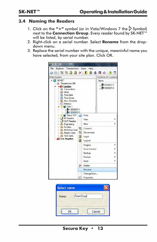
3.4 Naming the Readers
1. Click on the “+” symbol (or in Vista/Windows 7 the Symbol) next to the Connection Group. Every reader found by SK-NET™ will be listed, by serial number.
2. Right-click on a serial number. Select Rename from the drop-down menu.
3. Replace the serial number with the unique, meaninful name you have selected, from your site plan. Click OK.
SK-NET™ Operating & Installation Guide
Secura Key • 14
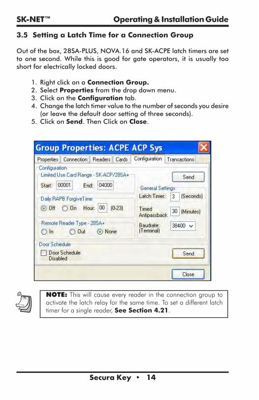
3.5 Setting a Latch Time for a Connection Group
Out of the box, 28SA-PLUS, NOVA.16 and SK-ACPE latch timers are set to one second. While this is good for gate operators, it is usually too short for electrically locked doors.
1. Right click on a Connection Group.2. Select Properties from the drop down menu.3. Click on the Configuration tab.4. Change the latch timer value to the number of seconds you desire (or leave the default door setting of three seconds).
5. Click on Send. Then Click on Close.
NOTE: This will cause every reader in the connection group to activate the latch relay for the same time. To set a different latch timer for a single reader, See Section 4.21.
SK-NET™ Operating & Installation Guide
Secura Key • 15
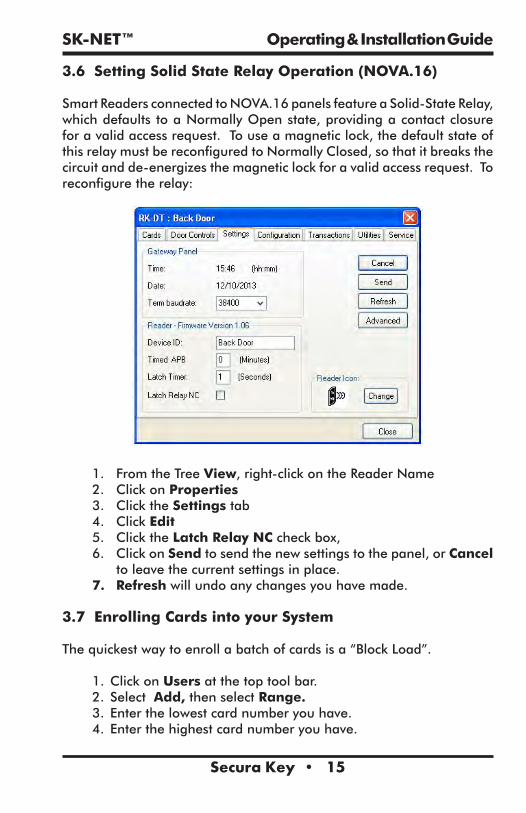
3.6 Setting Solid State Relay Operation (NOVA.16)
Smart Readers connected to NOVA.16 panels feature a Solid-State Relay, which defaults to a Normally Open state, providing a contact closure for a valid access request. To use a magnetic lock, the default state of this relay must be reconfigured to Normally Closed, so that it breaks the circuit and de-energizes the magnetic lock for a valid access request. To reconfigure the relay:
1. From the Tree View, right-click on the Reader Name 2. Click on Properties 3. Click the Settings tab4. Click Edit5. Click the Latch Relay NC check box, 6. Click on Send to send the new settings to the panel, or Cancel
to leave the current settings in place. 7. Refresh will undo any changes you have made.
3.7 Enrolling Cards into your System
The quickest way to enroll a batch of cards is a “Block Load”.
1. Click on Users at the top tool bar.2. Select Add, then select Range.3. Enter the lowest card number you have.4. Enter the highest card number you have.

SK-NET™ Operating & Installation Guide
Secura Key • 16
5. Select an Access Group for all the cards.6. Click OK. (All of these card numbers are now listed.)
NOTE: It is usually best to add a range of users/cards in the Void User group. The Access Group for each card can be changed when it is issued to a specific cardholder (See Section 5.1).
NOTE: If you anticipate adding additional Locations where cardholders from the first Location may need access, you should create those Locations in SK-NET™ before loading any cards in the first Location. For instructions in creating additional Locations See Section 4.1. (Multiple Locations require SK-NET-MLD version.)

SK-NET™ Operating & Installation Guide
Secura Key • 17
3.8 Testing the System
1. From the User View, double-click on one of the card numbers you have block loaded.
2. In the User Properties box, enter a name.3. In the Access Group field, select Master User.4. Click OK.5. Click the Send User Full arrow (in the top menu bar).
You now have one card that should unlock every door and open every gate in the system. Try it out.
6. View Transactions.
Make sure that every reader you visited appears in the Transaction list.

SK-NET™ Operating & Installation Guide
Secura Key • 18
4. CUSTOMIZE YOUR SYSTEM
4.1 Creating Additional Locations (MLD or Client-Server versions only)
Adding a new location:With SK-NET-MLD or SK-NET-MLD-CS XX versions you can create as many different locations as you need. A location is one or more Connection Groups, each consisting of SK-ACPE or NOVA.16 control panels or 28SA + readers connected together via RS-485 communications and operating as a unified system.
A new location is only required when you are connecting to a group of readers that require a different list of card users than those already being used in an existing location.
1. Click on the Explorer menu.2. Select New.3. Select Location.4. Name the New Location. Click OK.
Then use the procedure in Sections 3.2 and 3.3 to find and name the readers.

SK-NET™ Operating & Installation Guide
Secura Key • 19
4.2 Time Zones
A Time Zone is a schedule that governs when a card is valid (allowed access) and when it is invalid (denied access).
Most installations require that you customize one or more Time Zones and then create one or more new Access Groups before issuing cards to users. This allows you to grant access to users for specific doors at specific times and days.
Each Time Zone has a 24-hour schedule for each day of the week, as well as a 24-hour schedule for “holidays”. Any date designated as a holiday will follow the holiday schedule, regardless of what day of the week it falls on.
Because Time Zones are used to create Access Groups and define cardholder access privileges, Time Zones also include starting/ending dates as well as Anti-Passback Configuration.
SK-NET™ has sixteen Time Zones. Time Zone 0 is “Always Void”. (Void Users access group). Time Zone 1 is “Always Valid” (Masters Users access group). Time Zones 0 and 1 cannot be edited. Time Zones 2 through 15 can be edited any way you choose.
Location Time Zones can be edited for all readers from the Explorer/Tree View. You can also edit a time zone for a specific reader (See Section 4.12).
In an SK-NET™ System with multiple locations, you will have to setup Time Zones for each new Location that you create. These Time Zones can be completely different from the Time Zones in other Locations in the system.
4.3 Editing a Location Time Zone
1. Starting from the Tree View. Double-Click on Time Zones below the desired location.
2. Select the Time Zone you want to edit from the drop down list.3. Every square that is RED is a ½ hour increment when access will be denied. Every square that is GREEN is a ½ hour increment when access will be permitted. Click on squares to change them from RED to GREEN (or GREEN to RED).
4. After editing a Time Zone, click Save. You can undo any changes you have made by clicking Refresh.
5. After saving, click Send to send the time zone to all of the readers.

SK-NET™ Operating & Installation Guide
Secura Key • 20
NOTE: To change a block of squares from RED to GREEN, hold down the CONTROL key, click on the first square, then click on the last square. The square(s) in between will also change.
NOTE: To change an entire day from RED to GREEN, click on the big Green button to the left. To change an entire day from GREEN to RED, click on the big red button to the right.
NOTE: You can change the name of a Time Zone to something that reminds you of it’s function (i.e. “Day Shift” or “Cleaning Crew”.
4.4 Delaying the Start or End Time for the Half Hour Blocks
You may delay the start of a Time Zone, by entering a value (1-29) in the Delay Start field. This value equals how many minutes after the first GREEN increment begins when the card will become valid.
You may extend the end of a Time Zone by entering a value (1-29) in the Delay End field. This value equals how long after the last GREEN increment the card will continue to be valid.

SK-NET™ Operating & Installation Guide
Secura Key • 21
This feature will work for as many separate segments of time that are defined. So, for example, if you wanted to create multiple 50-minute time segments (as for a school bell schedule) you could enable a 30 minute block in each hour, and extend it by entering 20 minutes for the Delay End value.
4.5 Limiting the Dates a Time Zone is Active
Uncheck the Start Unrestricted box and use the calendar to select the first date the cards in this Time Zone should become active.
Uncheck the End Unrestricted box and use the calendar to select the last date that cards in this Time Zone should be valid.
NOTE: This feature is handy for clubs, gyms and other membership organizations.
NOTE: This feature does not apply to Time Zones 0 or 1.

SK-NET™ Operating & Installation Guide
Secura Key • 22
4.6 Antipassback
Antipassback is a feature designed to prevent card sharing and/or to enforce use of IN and OUT readers. When a card is used in an IN reader, its Anti-passback (APB) status is changed to IN. Conversely, when a card is used in an OUT reader, its APB status is changed to OUT. A card must be IN to be used in an Out reader, or OUT to be used in an In Reader. A card can be set to a Neutral APB Status (section 4.10) allowing it to be used in either an IN or OUT reader. APB status is not affected by using the card in a neutral (neither IN or OUT) reader.
Timed Antipassback does not require IN and OUT readers. After a card is used at a reader with Timed Antipassback, that card will not be valid at that reader for a predetermined amount of time (up to 30 minutes).
Real Antipassback requires readers for coming IN and going OUT. If a card was last used at an IN reader, it must be used at an OUT reader before it will be valid at an IN reader again.
NOTE: These features do not apply to Time Zones 0 or 1.
4.7 Selecting Antipassback for a Time Zone
Select the type of Antipassback you want from the list.
Hard Antipassback means that the card will be denied access, if used out-of-sequence at IN or OUT readers, and an “antipassback violation” will appear in Transactions.
Soft Antipassback means that the card will be granted access, if used out-of-sequence at IN or OUT readers, but an “antipassback violation” will appear in Transactions.
NOTE: Time Zones 0 and 1 cannot have antipassback.

SK-NET™ Operating & Installation Guide
Secura Key • 23
Soft-Antipassback is recommended for unsupervised parking lot applications to prevent traffic jams at the exits, when a cardholder’s APB status becomes out-of-sequence. Violations can be determined and discouraged by reviewing transaction reports and taking appropriate administrative action.
4.8 Timed Antipassback
To set the timed antipassback time for all readers:1. Right click on a Connection Group.2. Select Properties.3. Click on the Configuration tab.4. Enter the number of TAPB minutes (up to 30).5. Make sure the Latch Time is correct. Click on Send.
To set the timed antipassback time for a single reader:
1. Right click on the reader name.2. Select Properties. Click on the Settings Tab. 3. Click on the Edit button.4. Enter the number of TAPB minutes up to 30 minutes). Click on Send.
NOTE: Time Zones 0 and 1 cannot have any type of antipassback.
NOTE: To complete Timed Antipassback programming, you must create an Access Group using a Time Zone in the range 2 through 15 (See Section 4.14).

SK-NET™ Operating & Installation Guide
Secura Key • 24
4.9 Real Antipassback (RAPB)
To program Real Antipassback into your system, you must complete the following steps:
1. Select the proper antipassback configuration using a Time Zone in the range 2 through 15 (See Section 4.7).
2. Create an Access Group using a Time Zone in the range 2 through 15 (See Section 4.14).
3. You must define your readers as IN or OUT by dragging all of the IN readers into the IN Reader group and all of the OUT readers into the OUT Reader group.
4. If your system has more than one Connection Group, in order for RAPB to work properly, all of your Connection Groups must be connected to the system, and the SK-NET software must be running on your PC (it can be minimized).
NOTE: A Global RAPB Forgive All Command takes about ½ second per reader to process. On a 100-door system it will take approximately 50 seconds to reset Anti-Passback at all doors.
SK-NET™ Operating & Installation Guide
Secura Key • 25
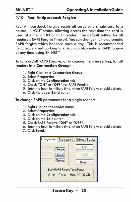
4.10 Real Antipassback Forgive
Real Antipassback Forgive resets all cards or a single card to a neutral IN/OUT status, allowing access the next time the card is used at either an IN or OUT reader. The default setting for all readers is RAPB Forgive Time off. You can change that to automatic RAPB forgive which happens once a day. This is recommended for unsupervised parking lots. You can also initiate RAPB forgive at any time using SK-NET™.
To turn on/off RAPB Forgive, or to change the time setting, for all readers in a Connection Group:
1. Right Click on a Connection Group.2. Select Properties.3. Click on the Configuration tab.4. Check “ON” or “OFF” for RAPB Forgive.5. Enter the hour, in military time, when RAPB Forgive should activate.6. Click the upper Send button.
To change RAPB parameters for a single reader:
1. Right click on the reader name.2. Select Properties.3. Click on the Configuration tab.4. Click on the Edit button5. Check RAPB Forgive “ON” or “OFF”.6. Enter the hour, in military time, when RAPB Forgive should activate.7. Click Send.
SK-NET™ Operating & Installation Guide
Secura Key • 26
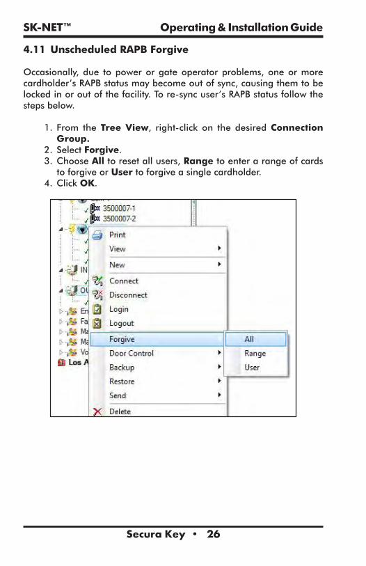
4.11 Unscheduled RAPB Forgive
Occasionally, due to power or gate operator problems, one or more cardholder’s RAPB status may become out of sync, causing them to be locked in or out of the facility. To re-sync user’s RAPB status follow the steps below.
1. From the Tree View, right-click on the desired Connection Group.
2. Select Forgive.3. Choose All to reset all users, Range to enter a range of cards to forgive or User to forgive a single cardholder.
4. Click OK.

SK-NET™ Operating & Installation Guide
Secura Key • 27
4.12 Editing a Time Zone for a Single Reader
1. From the Tree View, right-click on the selected reader.2. Select Properties.3. Click on the Door Controls tab, then click the Time Zones button.4. Select the Time Zone to be edited.5. Follow the procedures described in section 5.3.6. Click on Send. Then click OK. Close these boxes.7. Save settings when prompted.
Warning: If you do a Global Send for the Time Zone you have just edited, it will be overwrite the existing Time Zone for all readers in that location.

SK-NET™ Operating & Installation Guide
Secura Key • 28
4.13 Access Groups
An Access Group is assigned to each user defining which readers they have access to, and what times the readers can be used.
SK-NET automatically creates two default Access Groups:
The Master User group always includes all the readers in the location and is assigned Time Zone 1 (always valid). Master Users can use any reader at any time.
The Void User group also includes all the readers. It is tied to Time Zone 0 (Never valid). Placing a cardholder in the Void User group means he can never go anywhere, but his attempts to use the card will appear in Transactions.
4.14 Creating an Access Group
1. In the Tree View, right-click on This Location (or the new location name).
2. Select New.3. Select Access Group.4. Enter a group name. Enter a Time Zone for the group. Click OK.5. The name of the new Access Group now appears on the left side of the screen. At this point there are no readers assigned to this group.
6. Left click on the + next to Connection Group in the Tree View. A list of all the readers for that location will appear below.
7. Drag and drop the desired readers from the Connection Group into the new access group. Click on the + next to the new group and verify all the proper readers appear.
8. After changing all your users to the new Access Group be sure to click on “Send Users Full”.

SK-NET™ Operating & Installation Guide
Secura Key • 29
4.15 Changing a Reader’s Time Zone in an Access Group
Each reader in an Access Group could be assigned to a different Time Zone. To edit an Access Group:
1. Right Click on the Access Group name.2. Select Properties.3. Click on the Readers tab.4. Click on the “edit” icon (It looks like a little triangle).5. Change the Time Zones next to each reader name.6. Click on the “Send” button.7. Click on Close.

SK-NET™ Operating & Installation Guide
Secura Key • 30
4.16 Changing the Reader Icons
1. From the Tree View, right click on the reader name. Select Change Icon.
2. Select a suitable icon from the displayed menu. Click OK.
4.17 Door Schedules
A Door Schedule is used to automatically lock and unlock a door according to a regular weekly time schedule. Each Door Schedule has a 24-hour schedule for each day of the week, as well as a 24-hour schedule for “holidays”. Any date designated as a holiday will follow the holiday schedule, regardless of what day of the week it falls on.
You may set a Location Door Schedule for all the readers in the location, or you can set a Door Schedule for an individual reader.
Each reader in the system may have its own unique Door Schedule if required. Door Schedules are completely separate from the system’s Time Zones.

SK-NET™ Operating & Installation Guide
Secura Key • 31
4.18 Programming a Door Schedule
Location Door Schedule (All readers):1. In the Tree View, double-click on Door Schedule.2. Every GREEN square represents a ½ hour increment when the door will be unlocked. Every RED square is a ½ hour increment when it will be locked. Change the color of any square by clicking on it.
3. Select Automatic or Card Activate. Automatic means the door will unlock at the predetermined time. Card Activate means that the door will remain locked after the GREEN period begins until the next valid card is presented. This ensures that someone is in the building before the door unlocks.
4. For Door Schedules that do not conform to exact half-hours, use the Delay Start and Delay End feature. (See Section 4.4)
5. Click Send when finished.
NOTE: If you have a Door Schedule, you probably need to define Holidays.
NOTE: To temporarily override a door schedule, See Section 4.31d.

SK-NET™ Operating & Installation Guide
Secura Key • 32
Single Door Schedule1. In the Tree View, right click on the reader name.2. Select Properties3. Click on the Door Controls tab.4. Click on Schedule.5. Every GREEN square represents a ½ hour increment when the door will be unlocked. Every RED square is a ½ hour increment when it will be locked. Change the color of any square by clicking on it.
7. Select Automatic or Card Activate. Automatic means the door will unlock at the predetermined time. Card Activate means that the door will remain locked after the GREEN period begins until the next valid card is presented. This ensures that someone is in the building before the door unlocks.
8. For Door Schedules that do not conform to exact half-hours, use the Delay Start and Delay End feature. (See Section 4.4)
9. Click on Send. Click OK. Click on Close.
NOTE: If you have a Door Schedule, you probably need to define Holidays.
4.19 Holidays
Any date that is designated as a holiday will follow the Holiday schedule in Time Zones 2-15 and in any Door Schedules you have created. You may designate up to 32 dates as Holidays.
While it is usually best to create Holidays per Location (for all readers) you may also create a Holiday for a single reader.
4.20 Programming a Holiday
Location Holidays:1. In the Tree View, click on Holidays.2. Click on the “+” plus sign icon to add a Holiday.3. Enter the date of the Holiday. Type in a name for the Holiday. If the Holiday always falls on this date, check Yearly. Click OK.
4. To remove a Holiday, highlight the Holiday number and click on the “-“ minus sign.
5. To edit a Holiday, highlight the Holiday number and click on the edit icon (up arrow). Make changes to date or name and click OK.
6. After all Holiday additions or changes are made, click Send, then OK, then Close.

SK-NET™ Operating & Installation Guide
Secura Key • 33
NOTE: At the beginning of each new year, you need to review the Holiday schedule. Any Holiday which does not have a “YES” located in the yearly box needs to be changed.
4.21 Changing the Latch Timer for a Single Reader
1. Right-click on the name of the reader you want to change.2. Select Properties, then click on the Settings tab. 3. Click on the Edit button.4. Enter a new Latch Timer value (in seconds).5. Click on the Send button.6. Click on Close.

SK-NET™ Operating & Installation Guide
Secura Key • 34
4.22 Using the SecuRelay™
The SecuRelay™ is a module which allows Smart Readers to digitally control a relay. The SK-SR-1 is designed to be located inside the secure area, preventing potential intruders from gaining access to the building by pulling the reader off the wall and hot-wiring the latch circuit outputs. The Solid State Relay in the Smart Reader is actually a transistor switch, which can also transmit data. During its setup process, the SecuRelay™ learns the serial number of the Smart Reader. When the “Use Secure Relay” option is selected, for a valid access request, the Solid State Relay transmits the serial number of the smart reader to the SecurRelay™, which in turn activates the door locking mechanism.
If any readers in your installation use SK-SR-1 SecuRelays, the readers must be properly configured as follows:
1. From the Tree View, right click on the Reader Name2. Click Properties3. Click the Configuration Tab4. Click Edit5. Click the Use Secure Relay check box 6. Click Send to send the new settings to the panel, or Cancel
to leave the current settings in place. Refresh will undo any changes you have made.

SK-NET™ Operating & Installation Guide
Secura Key • 35
4.23 Date and Time
By default, every time you log into a location with your computer, the time and date in that computer can be transmitted to the system. If you prefer, you may manually set the system time using SK-NET™. (For example, if the computer is in a different time zone, you will want to set the time manually.)
Automatic Daylight Savings Time adjustments are handled by the system, unless you override this feature.
4.24 Setting the Time and Date
1. In the Tree View, right-click on This Location.2. Select Properties.3. Click on the Settings tab.4. Uncheck the Auto Time Synch box. Close.5. In the Tree View, click on Time/Date once to display current time and date settings.
6. Double-click on Time/Date to make changes.7. Click on Edit.8. Enter new time and date settings. Click Send. Click Close.
4.25 Configuring or Overriding U.S. Daylight Saving Time Feature
1. Check your firmware versions, by left clicking on all connection groups.2. To verify the firmware versions, look at the version column. If you are using NOVA.16 controllers, this screen will show the firmware version of the Smart Readers.
3. If all firmware versions are 2.43 or higher or if you are using NOVA.16 controllers, then stop here.
4. If you have any firmware versions 2.42 or lower then go to Option 2.5. If you are located outside the U.S. and use daylight savings then go to Option 2.
6. If your state does not change daylight savings, skip to Option 3.

SK-NET™ Operating & Installation Guide
Secura Key • 36
There are three options for configuring daylight saving time operation.
To select the Daylight Saving Menu:1. Right click on the Location Name.2. Select Properties
Option 1: Use the current U.S. daylight saving dates1. Select the Settings tab2. Select Auto (US) for the current United States Daylight Saving dates3. Click Send
SK-NET™ Operating & Installation Guide
Secura Key • 37
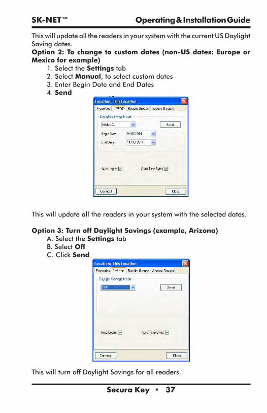
This will update all the readers in your system with the current US Daylight Saving dates.Option 2: To change to custom dates (non-US dates: Europe or Mexico for example)
1. Select the Settings tab2. Select Manual, to select custom dates3. Enter Begin Date and End Dates4. Send
This will update all the readers in your system with the selected dates.
Option 3: Turn off Daylight Savings (example, Arizona)A. Select the Settings tabB. Select OffC. Click Send
This will turn off Daylight Savings for all readers.

SK-NET™ Operating & Installation Guide
Secura Key • 38
4.26 IN and OUT Readers
SK-NET™ automatically creates a reader group for “IN” readers and a group for “OUT” readers. If your system has readers on both sides of an opening to control both access (entry) and egress (exit), you should place these readers in the IN and OUT groups.
When a reader is neither an IN or an OUT reader, valid card uses appear as “Valid Access” in Transactions. When a reader has been designated as an IN reader, the message will say “Valid Entry”. When a reader is designated as an OUT reader, the message will say “Valid Exit”:
Designating readers as IN and OUT is required in order to have Real Antipassback. (See Section 4.9, #3)
4.27 Programming an “IN” or an “OUT” Reader
1. In the Tree View, click once on Connection Group. This will cause all of the reader icons to appear on the right side of the screen.
2. Drag-and-Drop the appropriate readers onto the IN Reader group and the OUT Reader group on the left side of the screen.
3. Click on the “+” plus sign next to IN Readers and OUT Readers to verify the readers for each group.
4. Repeat steps for each Connection Group.

SK-NET™ Operating & Installation Guide
Secura Key • 39
4.28 Reader Groups
A Reader Group is used to set common properties for two or more readers. SK-NET™ automatically creates two Reader Groups: IN Readers and OUT Readers. You may create up to 25 additional Reader Groups as you wish.
4.29 Creating a Reader Group
1. From the Tree View, right-click on This Location (or the new location name).
2. Select New. Select Reader Group.3. Enter a name for the new Reader Group. Click OK.4. Click on the Group Name once. This causes all of the reader icons to appear on the right side of the screen.
5. Drag-and-Drop the desired readers from the right side of the screen onto the name of the new Reader Group.
NOTE:: Reader Groups are often used with Door Controls.
An “All Readers” group is useful to send parameters and configuration settings to systems with more than one Connection group. Without an All Readers group, you would have to send these parameters once for each Connection Group. SK-NET 5.0 does not automatically create an All Readers group, but you can easily create your own:
1. Right-Click on Location2. Select New, Reader Group, and name it “All Readers”3. Click OK.4. Then drag and drop all the readers from all of your Connection Groups into your new All Readers group. If you add any new readers to the system later, always be sure to add them to this group.

SK-NET™ Operating & Installation Guide
Secura Key • 40
4.30 Door Controls
Door Controls are functions that you can initiate from SK-NET™ that affect the door or gate at a connected location. Door Control icons appear at the top of the Tree View screen. You can send a Door Control command to a single reader, or to a Reader Group.
4.31 Using Door Controls
1. From the Tree View, click once on the name of a single reader or a Reader Group ( or a Connection Group).
2. Click on the Door Control icon for the function you want to initiate:a. Open The Door Now will activate the latch relay(s) for the
same time as presenting a valid cardb. Unlock The Door activates the relay and keeps it activated
until you restore it. During this time the GREEN LED on the reader will flash slowly.
c. Make Inactive (Locked) prevents even valid cards from gaining access through the door until you restore it. During this time the RED LED will flash slowly.
d. Disable Door Schedule is an override that relocks a door, or group of doors, that have been unlocked by a Door Schedule.
e. Make Active (Normal) restores a reader to normal operation after it has been placed in the Unlock or Inactive state by a Door Control command.
NOTE: Disable Door Schedule is useful when conditions require that a normally unlocked door be locked early. An example would be a school that has early dismissal due to bad weather.NOTE: A Global Door-Open Command takes about ½ second per reader to process. On a 100-door system it will take approximately 50 seconds to open all doors.NOTE: A Global Reader Inactive (lock-down) Command takes about ½ second per reader to process. On a 100-door system it will take approximately 50 seconds to inactivate all doors.

SK-NET™ Operating & Installation Guide
Secura Key • 41
4.32 Inputs
Inputs are circuits that connect external sensors or switches to a Smart Reader on a NOVA.16 panel or an SK-ACPE or 28SA-PLUS. This requires a momentary Normally Open contact switch. They are used to initiate special functions or to generate messages in Transactions. There are eight different Input definitions you can choose in SK-NET™.
NOTE: Input functions are associated with the reader or door connected to the same “side” of the SK-ACPE panel. With the NOVA.16, inputs are associated with each Smart Reader.
a. Disabled – The Input is not used.b. Tamper – A switch or sensor that has been installed to
detect interference with a component of the access control system. If this circuit is closed, the reader will be disabled and a Tamper message will appear in Transactions.
c. Arming Circuit – The reader is disabled until this input is closed. Cards presented while the Arming Circuit is open will be logged in Transactions but access will be denied. This input is often used for gates where a loop detector must sense that a vehicle is present before a card can be valid.
d. Door Monitor – Connected to a door position switch, this input activates anti-tailgate feature. It is also used to detect a door forced open or held open too long. (Anti-Tailgate – This feature cancels the latch time, once a door is opened and closed, preventing unauthorized persons from following a cardholder through a controlled door after a valid access.)
e . Door Bell – Sends an ASCII Bell Character to a PC or printer, causing an audible tone.
f. Remote Inactive – Closing this input makes the reader inactive (lockout).
g. Remote Open – This input activates the latch relay for the same amount of time as a valid card use. A “Door Opened Via Sensor” message appears in Transactions. Also called Request-To-Exit or REX.
h. User Defined – This input allows you to write a custom message that will appear in Transactions. The Input can be a variation of Remote Open or it can simulate Door Bell. It can also be used as an alarm reset for certain auxiliary relay output functions.

SK-NET™ Operating & Installation Guide
Secura Key • 42
4.33 Defining an Input
1. From the Tree View, right click on the Reader Name2. Select Properties 3. Click the Configuration Tab. The Configuration screen for Smart
Readers connected to a NOVA.16 panel differs slightly from the configuration screen for readers connected to SK-ACPEs, due to the additional inputs and outputs.
4. Click Edit 5. Select an input by clicking the Change button. 6. The Configure Input screen is displayed. Click on the Radio
button for the appropriate Input Type. Click the checkbox to Change the Input State if necessary (see the following paragraphs)
7. Click OK8. Click on the Send Button. Click Close.
The default state of Input circuits on the SK-ACPE and NOVA.16 Smart Readers is Normally Open, which is suitable for input devices such as REX Buttons or Tamper Switches. However some devices such as Door Monitor switches are typically Normally Closed when Secure, in which case, on the Configure Input screen, you must check the box labeled Change Input State to configure that input as Normally Closed.
NOTE: In the Security Industry, Normally Closed refers to the state of the switch contacts when a door is closed and the magnet and sensor are together, which is the NORMAL or Secure condition for a monitored door, as opposed to the OFF-NORMAL or Alarm Condition, which is an Open Circuit.
This applies to the new SK-ACPE, two-door control panel, as well as to Smart Readers connected to NOVA.16 control panels. Older SK-ACPs had an onboard jumper for this purpose, and the input had to be defined as a Door Monitor in the software for the jumper to change the Input State. In the newer SK-ACPE and NOVA.16, the Change Input State option is available for any input, regardless of whether or not it is defined as a Door Monitor.
NOTE: Be sure to back-up the changes when prompted.

SK-NET™ Operating & Installation Guide
Secura Key • 43
4.34 Outputs
Smart Readers connected to NOVA.16 panels have a solid state latch relay, plus two open-collector outputs for auxiliary functions. The SK-ACPE has a main (latch) relay and an auxiliary relay for each reader. (28SA-PLUS does not have an auxiliary output.) These extra relays or outputs can be activated by a variety of means to accomplish various functions.
• The relays can be connected to strobes or horns to annunciate security violations such as propped or forced doors.
• They can be activated by inputs or by a predefined range of cards to operate various types of equipment such as cameras, lighting or HVAC, also keeping a record of use.
• They can be used to shunt a door monitor contact connected to an external alarm system for any valid access transaction.
• Relay activation can be set for specified time duration, or it can be latched, and then canceled by presentation of a valid card.
The screen below is used to configure Outputs on an SK-ACPE

SK-NET™ Operating & Installation Guide
Secura Key • 44
The screen below is used to configure Outputs on a Smart Reader.
To configure AuxOutput operation for an SK-ACPE or for Smart Readers connected to a NOVA.16 panel, follow the steps below:
1. From the Tree View, right click on a reader name.2. Select Properties.3. Click on the Configuration tab.4. Click on Edit.5. Click on the Change button (to the right of ”Output” and the current configuration)
The Configure Output screen displays6. Select the desired Output definition. The parameter settings are displayed below the list of options7. Set any applicable Output Parameters - Click OK.8. Click on the Send button. Close.

SK-NET™ Operating & Installation Guide
Secura Key • 45
The following paragraphs will explain each of the Output Type options, available Output Parameter options, and how the output will work. For each output type you may select, different parameters will appear below the list of output types in the Output Parameters area of this screen.
1. Disabled
The output is not used.
2. Input 1 Follow / Latch
Whenever Input 1 is closed (activated) the aux. relay will activate and latch until (select option by clicking the adjacent radio button):
1) a valid card is presented to the reader2) a User Defined Input 2 is activated 3) a pre-selected amount of time elapses (Max mm:ss=59:59)4) Input 1 is opened (restored)
Typical Application: allows a switch (PIR, pushbutton, relay output) to activate a relay-controlled device (horn, strobe, camera, HVAC, lighting) which can be cancelled by various means.
3. Input 2 Follow / Latch

SK-NET™ Operating & Installation Guide
Secura Key • 46
Whenever Input 2 is closed (activated) the aux. relay will activate and latch until (select option by clicking the adjacent radio button):
1) a valid card is presented to the reader 2) a User Defined Input 1 is activated3) a pre-selected amount of time elapses (Max mm:ss = 59:59) 4) Input 2 is opened (restored)
Typical Application: allows a switch (PIR, pushbutton, relay output) to activate a relay-controlled device (horn, strobe, camera, HVAC, lighting) which can be cancelled by various means.
4. Door Monitor Alarm
If one of the Inputs is configured as Door Monitor, the aux output will activate if the door is forced open or if it is left open too long. A Forced Door condition occurs if the door is opened, and neither a valid card transaction nor a REX activation has occurred.
A DOTL (door-open-too-long) condition normally occurs after a valid card access or REX activation, if the door is still open at the end of the latch time. Entering a time value into the Expiration Time field will delay the start of the DOTL status beyond the latch time.
If this Output Type is selected, once the Door Forced or DOTL condition exists, the Aux relay will stay energized as long as the door continues to be held open. Once the door is closed, you have three options to turn the relay off (select option by clicking the adjacent radio button):
1) a valid card is presented to the reader 2) a User Defined Input is activated3) a pre-selected amount of time elapses (Elapsed time 59:59 mm:ss max)
Note that if Elapsed Time is selected and set to 0, the relay will deactivate as soon as the door is closed.

SK-NET™ Operating & Installation Guide
Secura Key • 47
Typical Application: allows output contact to provide a warning that a controlled door was propped or forced open, which can be connected to a central station alarm panel, or to a local annunciator (horn, strobe) alerting local security personnel.
5. Door Forced Alarm
If one of the Inputs is configured as Door Monitor, this output will activate if the door is forced open. This output is typically connected to a local alarm signal or to a remote monitoring station. Once the auxiliary relay is activated it will remain activated until (select option by clicking the adjacent radio button):
1) a valid card is presented to the reader2) a User Defined Input is activated,3) a pre-selected amount of time elapses.
Typical Application: allows output contact to provide a warning that a controlled door was forced open, which can be connected to a central station alarm panel, or to a local annunciator (horn, strobe) alerting local security personnel.
6. Door Held Open

SK-NET™ Operating & Installation Guide
Secura Key • 48
If one of the Inputs is configured as Door Monitor, the aux output will activate if the door is held or propped open too long after a valid card access or REX activation. Normally, a DOTL (door-open-too-long) condition occurs if the door is still open at the end of the latch time. Entering a time value into the Expiration Time field will delay the start of the DOTL status beyond the latch time.
Note that if Elapsed Time is selected and set to 0, the relay will deactivate as soon as the door is closed.
Typical Application: allows output contact to provide a warning that a controlled door was propped open, which can be connected to a central station alarm panel, or to a local annunciator (horn, strobe) alerting local security personnel.
7. Emergency Exit Alarm
Used when one of the Inputs is designated as Remote Open, in which case, the auxiliary relay will activate whenever the main relay is triggered via the Remote Open Input. This is typically used to sound a local alarm when the door has been used for egress.
If this Output Type is selected, once the Remote Open is used, the Aux relay will stay energized. You have three options to turn the relay off (select option by clicking the adjacent radio button):
1. A valid card is presented to the reader2. A user-defined input is activated3. A pre-selected amount of time elapses (Max mm:ss = 59:59)
Typical Application: allows output contact to provide a warning that a controlled door was opened, which can be connected to a local annunciator (horn, strobe) alerting local security personnel.

SK-NET™ Operating & Installation Guide
Secura Key • 49
8. Card Range
Cards in a selected range will activate the auxiliary relay only or both the auxiliary and main relays. Typically this is used so specific cards can cause something special or extra to happen. The relay can be set to Toggle, (activate until another card in the selected range is presented) or to activate for a preset amount of time. If you select the Card Mode Timed button, the Expiration Time field will appear below.
Typical Application: allows output contact to be activated by designated card holders, to operate a relay-controlled device (HVAC, lighting, additional door/gate, process control) separately or in conjuction with opening the controlled door, for a configurable time, or until canceled by a card in the same range.
9. Error Alarm
When any one of selected “Error” conditions occur, the auxiliary relay will activate and stay activated until a valid card is presented to the reader. You can select one or multiple conditions by clicking on the desired check boxes. Error Conditions you may select from are “Door Forced”, Door Held”, Tamper Input”, “Void User”, “Invalid Facility Code”, “Antipassback Violation”, “Arming”, “Tamper Card”, “Inactive”, “Invalid ID”, “Time Zone Error”, “Time Zone Date”, “Limited Use Violation”.

SK-NET™ Operating & Installation Guide
Secura Key • 50
Typical Application: Provide a local warning (horn, strobe, etc) for various card access exceptions, alerting security personnel to security breaches, intrusion or illicit entry attempts.
10. Serious Alarm
When any one of the following “Error” conditions occur, the auxiliary relay will be activated and remain activated until a valid card is presented: “Void Card”, “Invalid Facility Code”, ”Tamper”, “Door Forced”, “Door Held”. This group of conditions is pre-selected in the software, so no options are displayed in the Output Parameters section.
Typical Application: Provide a local warning (horn, strobe, etc) for various card access exceptions, alerting security personnel to security breaches, intrusion or illicit entry attempts.
11. Time Zone
The auxiliary relay will be activated during the GREEN increments of the selected Time Zone.
SK-NET™ Operating & Installation Guide
Secura Key • 51
Typical Application: Allows scheduled operation of any relay controlled device (HVAC, lighting, an additional door/opening, alarm shunt circuit, keypad).
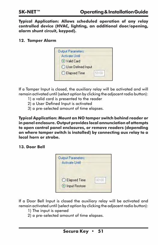
12. Tamper Alarm
If a Tamper Input is closed, the auxiliary relay will be activated and will remain activated until (select option by clicking the adjacent radio button):
1) a valid card is presented to the reader2) a User Defined Input is activated 3) a pre-selected amount of time elapses.
Typical Application: Mount an NO tamper switch behind reader or in panel enclosure. Output provides local annunciation of attempts to open control panel enclosures, or remove readers (depending on where tamper switch is installed) by connecting aux relay to a local horn or strobe.
13. Door Bell
If a Door Bell Input is closed the auxiliary relay will be activated and remain activated until (select option by clicking the adjacent radio button):
1) The input is opened 2) a pre-selected amount of time elapses.

SK-NET™ Operating & Installation Guide
Secura Key • 52
Typical Application: output provides local annunciation of a non-cardholder using a doorbell button to request access from staff or security personnel, for use at public entrances, gates, or shipping/receiving areas.
14. Alarm Shunt
Whenever the main relay is activated by a valid card or a Remote Open input, the auxiliary relay will be activated and will remain activated until (select option by clicking the adjacent radio button):
1) the main relay returns to normal 2) a pre-selected amount of time elapses
Typical Application – used to suppress a Door Monitor Contact which is connected to an external Central Station Alarm System, to prevent false alarms from being reported. The elapsed time should be set long enough for a person to pass through the door, allowing additional time when appropriate for bringing product, equipment or luggage through the door on carts or hand-trucks. (Note that some newer alarm monitor contacts are digital devices, which cannot be shunted in this manner.)
4.35 Programming Custom Wiegand Data Formats
1. From the Tree View, right-click on the reader name.2. Select Properties.3. Click on the Service tab.4. Click on Edit.5. Uncheck Use Defaults.6. Enter the total number of bits in your card format.7. Use the slide scale to set the number of card I.D. bits to 16.8. If normal parity bits are not used check No Parity and verify whether the card number is correct. You may have to reposition the slide scale after you check No Parity. If not, select Ignore Parity.

SK-NET™ Operating & Installation Guide
Secura Key • 53
9. Click Send to change settings for that reader only. Click Send to All if all the readers require these settings.
NOTE: This feature is not supported with the 28SA Plus.
NOTE: Be sure to back-up the changes when prompted.
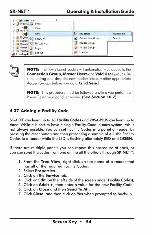
4.36 Adding New Readers to the System
After a new control panel has been installed and wired into the system, hold in the reset button while turning on the power. Hold the button for 3 seconds until you hear a double beep and release. SK-NET™ will now be able to find the new reader(s).
1. From the Tree View, right-click on Connection Group.2. Select New.3. Select Reader(s).4. Select Quick Find (unless you have more than 20 readers, then use Search).
5. SK-NET™ will find the new reader(s) and bring them into the system. Follow the prompts until the new readers have been logged in.
SK-NET™ Operating & Installation Guide
Secura Key • 54
NOTE: The newly found readers will automatically be added to the Connection Group, Master Users and Void User groups. Be sure to drag-and-drop the new readers into any other appropriate Access Groups before you do a Card Send.
NOTE: This procedure must be followed anytime you perform a Power Reset on a panel or reader. (See Section 10.7)
4.37 Adding a Facility Code
SK-ACPE can learn up to 16 Facility Codes and 28SA-PLUS can learn up to three. While it is best to have a single Facility Code in each system, this is not always possible. You can set Facility Codes in a panel or reader by pressing the reset button and then presenting a sample of ALL the Facility Codes to a reader while the LED is flashing alternately RED and GREEN.
If there are multiple panels you can repeat this procedure at each, or you can send the codes from one unit to all the others through SK-NET™.
1. From the Tree View, right click on the name of a reader that has all of the required Facility Codes.
2. Select Properties.3. Click on the Service tab. 4. Click on Edit (on the left side of the screen under Facility Codes), 5. Click on Add++, then enter a value for the new Facility Code. 6. Click on Close and then Send To All.7. Click Close, and then click on Yes when prompted to back-up.

SK-NET™ Operating & Installation Guide
Secura Key • 55
Now that all the readers have been updated with new facility codes, you need to update the database files in SK-NET™.
1. From the Tree View, right click on Location.2. Select Backup.3. Select All Readers
NOTE: Sending Facility Codes via SK-NET™ is not supported by the 28SA-PLUS.
NOTE: Be sure to back-up the changes when prompted.
SK-NET™ Operating & Installation Guide
Secura Key • 56
5. MANAGING USERS
The User screen displays all cards and associated cardholders. This is where you can add a card, edit card details, monitor in and out status and generate user reports.
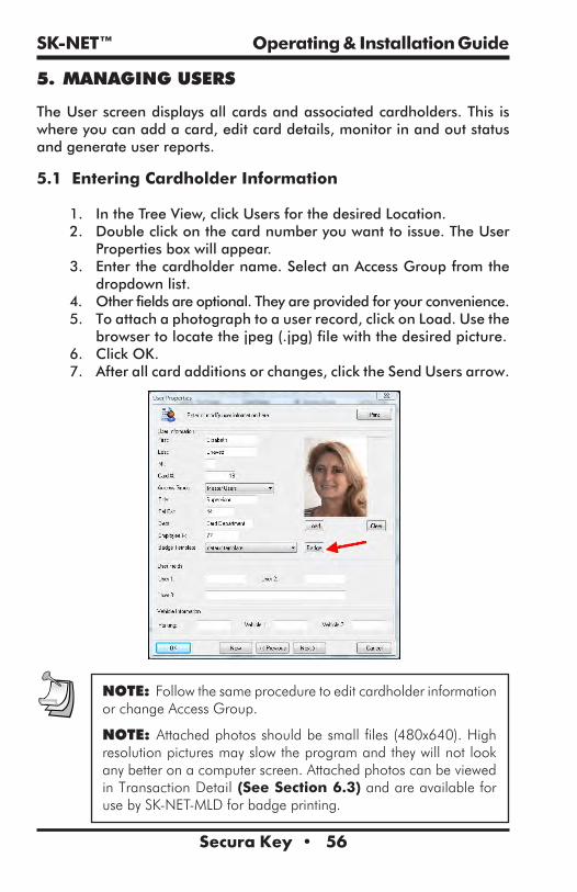
5.1 Entering Cardholder Information
1. In the Tree View, click Users for the desired Location. 2. Double click on the card number you want to issue. The User
Properties box will appear.3. Enter the cardholder name. Select an Access Group from the
dropdown list.4. Other fields are optional. They are provided for your convenience.5. To attach a photograph to a user record, click on Load. Use the
browser to locate the jpeg (.jpg) file with the desired picture. 6. Click OK.7. After all card additions or changes, click the Send Users arrow.
NOTE: Follow the same procedure to edit cardholder information or change Access Group.
NOTE: Attached photos should be small files (480x640). High resolution pictures may slow the program and they will not look any better on a computer screen. Attached photos can be viewed in Transaction Detail (See Section 6.3) and are available for use by SK-NET-MLD for badge printing.

SK-NET™ Operating & Installation Guide
Secura Key • 57
5.2 Adding a New Card Number
1. In the Tree View, click on Users for the desired location. 2. In the User View, click on the “+” sign (Add).3. In the User Properties box, enter the cardholder name.4. Enter the Card Number.5. Select an Access Group from the drop down list.6. Enter additional data and/or attach photos if desired.7. Click OK.8. After all card additions or changes, click the Send Users arrow.
5.3 Deleting a User
NOTE: You can remove a card completely from the system. It is usually better, though, to edit the card and make it a Void User. This ensures that the card will not be granted access, but each attempted use will be recorded in Transactions.
To remove a single card:
1. In the Tree View, click on Users for the desired location. 2. In the User View, click on the card number to be removed. This
will position the pointer next to that number.3. Click on the “X“ (Delete). The record will be removed.4. After any card additions or changes, click the Send Users arrow.
NOTE: Be sure to backup your system when you exit SK-NET™.
5.4 Changing the Names of User Data Fields
1. Click on the word File in the top menu bar.2. Select Preferences.3. Click on the User Field Labels tab.4. Change the text to be displayed for any of the field labels shown. Click OK.

SK-NET™ Operating & Installation Guide
Secura Key • 58
5.5 Sorting Cardholders in the User List
When the User list is displayed, you can sort the User List by clicking on many of the column headings. For example, clicking on Last Name will sort the list alphabetically by last name. Clicking on Card Number will sort the list from lowest to highest card number.
You may also find a specific card or user by clicking on Users on the top menu bar, then select Find. Select the search field (Last Name, Card Number, Title, etc.) and enter the corresponding value. A pointer on the left side of the list will move to the desired record.
5.6 Filtering Users
Filters allow you to temporarily remove unwanted records from the list. This allows a limited user report to be generated, for example, users in a single department or users who are out of the building.
1. From the User View, click on the Filter Users icon. 2. In the Filter Users detail box, select Anti-Passback Status and/or
Department. Note that “IN or OUT” excludes all “neutral” users. 3. Enter the desired filter value. Click OK. 4. To remove any applied filters, repeat the process and select ALL for each filter type.
For more information on User Reports see Section 7.2.

SK-NET™ Operating & Installation Guide
Secura Key • 59
NOTE: Users in a particular Access Group can be filtered by simply clicking on the User icon under a particular Access Group icon.
5.7 Limited Use Cards
Limited Use Cards are valid for a specific number of uses, days or weeks. After the preset limit is reached, the cards become Void. Limited Use Cards can also be set to “Count”. This feature keeps track of card uses, but does not automatically void the card.
Limited Card usage is shared between all of the readers in a location, but it is not transmitted from one location to another. It is usually best to set up Limited Use Cards globally, but they may also be created in a single reader or a Reader Group.
In systems using legacy hardware (SK-ACP or 28SA+) a maximum of 4000 contiguously numbered cards can be used as limited use cards. By default, the range is set to 1 – 4000. With the newest control panels (SK-ACPE and SK-MRCP or NOVA.16) any card (1-65535) can be a limited use card.
Limited Use parameters can be assigned to one card or a contiguous range of cards. To assign these parameters to a specific group of cardholders, a contiguous block of card numbers must be issued to that group.
5.8 Programming Limited Use Cards
1. In the Tree View screen, right-click on a Connection Group.2. Select Properties.3. Click on the Configuration tab.

SK-NET™ Operating & Installation Guide
Secura Key • 60Secura Key • 60
4. For legacy panels/controllers, enter the lowest and highest Limited Use Card numbers from among the cards enrolled in your system. (No more than 4000 cards may be Limited Use.)
5. Click Send.6. Click on the Cards tab.
7. Select the appropriate Limited Use parameter. Enter a count value, where required.
8. Enter the lowest and highest cards within the previously defined limited use card range, that applies to this parameter. (You can define multiple groups of Limited Cards with various limitation parameters.)
9. Click Send. Click Close.

SK-NET™ Operating & Installation Guide
Secura Key • 61
NOTE: A similar process can be used in the properties of a Reader Group or of a single reader. It is usually better to make Limited Use Cards Location-wide.
NOTE: Limited Use cards cannot be programmed into Time Zone 1 or Master Users.
NOTE: When the Uses parameter is selected, the system does not count uses involving an OUT reader.
NOTE: To reprogram a void Limited Use card, follow the programming steps above for the desired card or card range.
NOTE: If your system has more than one Connection Group, in order for the Limited Use “Uses” or “Counter” function (number of uses) to work properly, all of your Connection Groups must be connected to the system, and the SK-NET™ software must be running on your PC (it can be minimized). Once programmed, the Limited Use “Days”, “Days after Use”, and “Weeks” functions will continue to work, even if the SK-NET™ software is not continuously connected or running.
To view current limited use programming, from the Tree View, right-click on a reader in the desired location, click Properties, click the Cards tab, then click the Display button, and a list of card numbers, will display with time zones, limited use programming and user names. Click the Print button to print this list.
5.9 Integrated Badge Printing
SK-NET™is capable of printing ID badges using any windows-compatible ID card printer. SK-NET™ Badge Printing is template based, which allows the user to create professional looking badges.
SK-NET™ Badge printing allows you to design and name custom badge templates which can be assigned to individual classes of card holders (for example, at a Hospital, you can design and save different badge templates for Nurses, EMTs, Facilities, Doctors, etc.)
To start creating badges, start SK-NET™, then double-click on Users.

SK-NET™ Operating & Installation Guide
Secura Key • 62
Select a User name, then in the area below the user’s photo, click on the Badge button. The Badge Layout Definition screen will then appear. To select a template to start with, click the drop down menu labeled “Badge Type.” You can choose from seven different standard templates:

SK-NET™ Operating & Installation Guide
Secura Key • 63
Standard Portrait 1 Logo on top, name above photoStandard Portrait 2 Logo on top, name below photoStandard Portrait 3 Logo on bottom, name above photoStandard Landscape 1 Logo on top, photo on left sideStandard Landscape 2 Logo on top, photo on right sideStandard Landscape 3 Logo on top, large photo on left sideStandard Landscape 4 Logo on top, large photo on right side
An image of the current badge design is shown on the left side of the screen. Configuration parameters are on the right side of the screen.

SK-NET™ Operating & Installation Guide
Secura Key • 64
Badge LayoutWhen configuring the badge layout, for each data field, a check box allows the user choose whether or not to “Show” that field. For each field, the user can select a Font, font color, and point size. Name Options allows you to select the display order of First Name, Last Name and MI. The “With Punch Hole” check box will reformat the card layout to allow for a slot punch. The Prefix field allows you to insert a prefix text before each data field, such as Card No:, Employee No:, etc.
Inserting LogoTo insert a company or organization logo, first save a JPEG of the logo onto your computer’s hard drive, then check the Show Logo check box, then click on Load, and you can browse your disk drive to find the logo file. The logo should be correctly sized to fit on the card, but SK-NET™ will center and size the logo to fit into the card layout. To make the logo appear correctly, click on the transparent check box, and select the appropriate color to be transparent.
Creating TemplatesThe Static Text field allows you to enter text that is not a database field. This is useful when setting up templates for various cardholder job classifications, for example, at a hospital, you can define a different Badge Template for NURSES, DOCTORS, EMTs, MAINTENANCE, etc. Once you have set up the artwork the way you want it, click on Save As, and then overwrite the text “default template” which appears in the popup box, by typing the new template name.
Card BackgroundsThe Show Wallpaper check box allows you to use a JPEG image file as a background for the card. This can be an interesting texture, or you can design and create a custom card background in Photoshop and save it as a JPEG onto your computer’s hard drive. Then check the Show Wallpaper check box, then click on Load, and you can browse your disk drive to find the Wallpaper file. The logo should be correctly sized to fit on the card, but SK-NET™ will center and size the Wallpaper to fit into the card layout.
If you don’t have a wallpaper or pre-designed background for the card, SK-NET™ will allow you to select a color for the background, and choose from several different types of gradiated washes. If you are designing a number of different Badge Templates for your organization, you may want to give them different colored backgrounds, so that they can be visually recognized at a distance.
NOTE: If you choose a dark background, you may need to select a light color for text fields, to make them easier to read against the dark background.

SK-NET™ Operating & Installation Guide
Secura Key • 65
Text AlignmentThe Text Position radio buttons allow you to align text fields for the best appearance. The Left Adjust and Top Adjust fields allow you to enter a value to change the alignment of the artwork on the card. You can enter a number from 1-10 in the field. Normally, you should not have to use these fields.
Two-Sided PrintingThe Two-Sided Printing check box should be used if you have a dual-sided card printer, and if you intend to print text or a bar code on the back of the card. If you want to print both sides of the card, be sure to set two-sided printing in your Printer Properties definition, or the card will not flip over and you will print the front and back images on two different cards.
To design the back of the card, click on the Back tab on the Badge Layout screen. You can type in any text that you want to appear on the back of each card, such as a “Return Card to” address, or a “Not Responsible for Damages” disclaimer for a parking lot.
You can also select which data field is used to create the bar code, and then you can select the type of Bar Code to be used.
Most two-sided printers will print the front of the card in four-colors, and the back of the card in resin black, and many printers have a special ribbon which has an extra resin panel for printing the back of the card.

SK-NET™ Operating & Installation Guide
Secura Key • 66
Slot Punching Cards with ArtworkDo not slot punch your cards prior to printing, and be careful to slot punch the cards at the slot punch targets marked “+” to avoid damaging the antenna in the card. If you have already slot punched your cards, adjust your layout so that you will not be printing anything in the area of the slot, as the sharp edge of the slot tends to tear dye sublimation printer ribbons.
Avoiding Printing ProblemsAccess control cards may contain embedded integrated circuits or “chips,” antennas, inlays, Wiegand code strips, or magnetic material. These embedded materials may be made more obvious if you print the card with a ‘full-bleed” solid color background. If the embedded components cause the card surface to be uneven, the dye sublimation print head may lose contact with the card at the point where it passes over a high spot, causing a white spot or “printing void” in the card background. To avoid printing problems, a white background will provide better results than using a solid color. Also, do print some test cards before you begin to print large quantities of cards. If you notice that the cardholder’s portrait appears over a printing void caused by embedded components, you can choose another standard template, which changes the location of the photo.
When handling cards prior to printing, use powder-free gloves, and hold the cards by the edges – do not get fingerprints or oil from your skin on the cards. PVC cards have a static charge, and they attract dirt and debris, which cause printing problems, so use your printer’s cleaning card and head cleaning pen, and keep your work area as clean as possible. If your cards should get dirty, use a soft cloth and 99% Isopropyl Alcohol to clean each card prior to printing.

SK-NET™ Operating & Installation Guide
Secura Key • 67
6. MANAGING TRANSACTIONS
The Transaction view displays system activity. Card events that are valid and invalid are displayed, along with system events such as a door unlocked by a Door Schedule or automatic RAPB Forgive.
Transactions can be displayed in a list, with the most recent event at the bottom of the screen. You can also display a single transaction in detail, including any attached photograph for the cardholder.
6.1 Changing Transaction View1. From the Transaction screen, click on the Change Colors icon.2. Click the Change box next to the event type you want to alter.3. Select a color from the chart. Click Apply to preview how the color will look. (Some colors are very hard to read.) Click OK to use the selected color.
4. To change whether a transaction class appears Bold or Italic, click the appropriate check box.

SK-NET™ Operating & Installation Guide
Secura Key • 68
6.2 Filtering Transactions
1. From the Transactions screen, click on the Filter icon.2. In the Transaction Filter box, select one or more filter criteria types. Each filter criteria requires a value to be entered.
3. Click OK.4. To remove any filters, repeat the process and select ALL for each filter criteria (or click on Defaults to reset all filters.)
NOTE: To View Transactions of Users from a particular Access Group or location, simply click on the Transactions icon under a particular Access Group or location.
6.3 Viewing Cardholder Photos When They Badge
If you have loaded Cardholder photos into the software, this option allows the system operator to see a photo in real time when a badge is presented. This allows you to compare the cardholder photo with video from a live camera if you need to positively ID cardholders before allowing them to enter. If the photo matches the live cardholder, you can use a Remote Open button to admit the cardholder.
1. From the Transaction View, click on the Zoom In icon (magnifying glass icon).
2. The selected transaction will be displayed with user details and photo (if loaded), To view previous transactions, use the navigation buttons.

SK-NET™ Operating & Installation Guide
Secura Key • 69
6.4 Archiving Older Transactions
1. From the Transaction View, click on the word “Transactions” in the top menu bar.
2. Select Archive, then New/Append.3. Click on the New File button and enter a name for the archive file destination.
4. If you do not want to archive all the transaction records, click on both “Events On” buttons and enter a starting and/or ending date.
5. Click OK.
NOTE: In the same menu you may choose to delete an archive file that you no longer wish to retain.

SK-NET™ Operating & Installation Guide
Secura Key • 70
6.5 Viewing Archived Transactions
1. From the Transaction View, click on the drop-down menu to Select Transactions to View.
2. Select the archive file you want to see.3. You may navigate through archived transactions the same way you navigate through current transactions.
6.6 Excluding Transaction Types
You may exclude specific transaction types from the system audit trail. Transaction types to exclude can be selected from the connection group or for individual readers. Excluding some transaction types reduces the number of event records in Transactions and also conserves space in the event buffer of the panel and/or 28SA-PLUS.
NOTE: Excluded transactions are not stored by the software or at the panel - they can not be recovered later.
NOTE: If you have more than one connection group and you want to exclude one or more transactions from all of the readers, we recommend that you create an “All Readers Group”. This will allow you to send this command one time and apply the change to all readers in the system. See Section 4.29.
6.7 Excluding Transaction Types for All Readers
1. From the Tree View, right-click on a Connection Group.2. Select Properties.3. Click on the Transaction tab.4. Place a check mark next to each transaction type you want to exclude. Click Send.
5. This procedure must be completed for every connection group in the location.
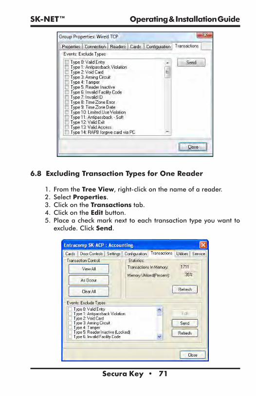
SK-NET™ Operating & Installation Guide
Secura Key • 71
6.8 Excluding Transaction Types for One Reader
1. From the Tree View, right-click on the name of a reader.2. Select Properties.3. Click on the Transactions tab.4. Click on the Edit button.5. Place a check mark next to each transaction type you want to exclude. Click Send.

SK-NET™ Operating & Installation Guide
Secura Key • 72
7. REPORTS
7.1 Transaction Reports
1. From the Tree View, click Transactions and apply the appropriate Filters required to isolate the events of interest.
2. Click on the Print icon to preview the report.
3. To Print the report click on the Printer icon again.
To Save the Report:1. Click on the Export icon
2. Select the file format for the report you wish to save.3. Make your selections, click OK to save the report.

SK-NET™ Operating & Installation Guide
Secura Key • 73
7.2 User Information Reports
1. From the User View, sort and Filter the list the way you want it to appear on the report.
2. Click on the selector arrow next to the print icon and choose either the User Report or User Detail Report.
3. To Print the report click on the Printer icon4. Make your selections and click OK to print.
To Save the Report:1. Click on the Export icon
2. Select the file format for the report you wish to save.3. Make your selections, click OK to Save the report.

SK-NET™ Operating & Installation Guide
Secura Key • 74
7.3 Print a System Report (List of readers in a location)
This report includes the Reader Name, Serial Number, Node ID, Firmware Version, and panel type for each Connection Group, Reader Groups and Access Group in the Location.
1. Highlight the Location name.2. Click on the Print button to view the report.
3. To Print the report click on the Printer icon again4. Make your selections and click OK to print.
To Save the Report:
1. Click on the Export icon2. Select the file format for the report you wish to save.3. Make your selections, click OK to save the report.

SK-NET™ Operating & Installation Guide
Secura Key • 75
7.4 Printing a List of Users in an Access Group Report
1. Select the Access Group and highlight Users.
2. Select the User Report Type.
3. To Print the report click on the Printer icon4. Make your selections and click OK to print.

SK-NET™ Operating & Installation Guide
Secura Key • 76
To Save the Report:
1. Click on the Export icon
2. Select the file format for the report you wish to save.3. Make your selections, click OK to save the report.

SK-NET™ Operating & Installation Guide
Secura Key • 77
8. SECURITY
8.1 Changing an SK-NET™ Operator Password
1. Click on File in the top menu bar.2. Select Operator.3. Select Change Password.4. Enter the new password twice. Click OK.

SK-NET™ Operating & Installation Guide
Secura Key • 78
8.2 Assigning Operator Levels
Client/Server versions of SK-NET-MLD allow you to enroll numerous operators, each with a unique password. Operators can be assigned to one of five different privilege levels:
a. Guards – Able to view Transactions.b. Receptionists – Able to view User IN/OUT status.c. Card Issuer – Able to perform functions in the User
screen.d. Supervisors – Able to perform functions in all screens,
but not able to change system parameters or Location properties.
e. Administrators – Full software privileges.
1. Click on File in the top menu bar.2. Select Operator.3. Select Add (+).4. Enter the operator name, password twice and select the privilege level. Click OK.

SK-NET™ Operating & Installation Guide
Secura Key • 79
8.3 System Activity Log
The System Activity Log records what the operators of SK-NET™ have been doing in the software. It records the Operator, Date, Time, and what action was performed.
1. Click on File in the top menu bar.2. Select Operator.3. Select View Activity Log.4. Scroll up or down to see operator activity.
8.4 Password Protection
To prevent intruders from hacking into a location, SK-NET™ has a second set of passwords that are exchanged behind the scenes whenever a computer running SK-NET™ attempts to connect to a Location. This invisible password can, and should, be changed from the default (12345).
1. From the Tree View, make sure that you are Connected to the Location where you want to set a new Password (see bottom of screen).
2. Right-click on the Location.3. Select Properties.4. Click on the Key icon (to the right of the word “Password”.5. Enter the new password twice. Click Save.
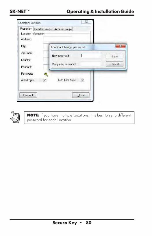
SK-NET™ Operating & Installation Guide
Secura Key • 80
NOTE: If you have multiple Locations, it is best to set a different password for each Location.

SK-NET™ Operating & Installation Guide
Secura Key • 81
9. DIAGNOSTICS
9.1 Communicating with a Location
In the Tree View, a red triangle next to the Location icon (the little red building) indicates that you are connected to that Location. A lightning bolt next to a Connection Group means that the connection is active.
A green check mark next to a reader icon indicates that you are logged in to the reader. Being “logged in” means that complete, real-time communication is occurring, and that all the stored transactions have been downloaded to SK-NET™.
Reader icons with red “X’s” through them are readers that have failed to log in.
9.2 Network Messages
If you place the software in the Debug mode, you will see network messages displayed at the bottom of the screen.
1. Click on the word File in the top menu bar.2. Select Preferences.3. Click on the Settings tab.4. Place a check mark next to Turn on System Message View.5. Click Apply.To see the message, click on the Messages tab at the bottom left of the screen.

SK-NET™ Operating & Installation Guide
Secura Key • 82
9.3 Self Testing from SK-NET™
You may initiate a self-test using SK-NET™.
1. From the Tree View, right-click on the name of the reader you want to test.
2. Select Properties. 3. Click on the Utilities tab.4. Click the Refresh button under Self-Test. Each item will display a Pass/Fail result.
9.4 Backup Battery Monitoring
The Battery Monitoring feature is included in the new SK-ACPE-LE control panel, and the NOVA.16 control panel. The control panels can be connected to optional rechargeable backup batteries (SK-BAT) which operate the panel during AC power failures. The control panel monitors battery health, and transmits battery status transaction messages to the SK-NET 5.1 software. From the Reader Properties/Utilities screen of an associated reader, the operator can enable or disable the Battery Monitoring feature, and display the current Battery status for the SK-ACPE or NOVA.16. Note that the Door Locking mechanisms will also need separate battery backup for the Access Control System to fully function during a power outage.

SK-NET™ Operating & Installation Guide
Secura Key • 83
To configure Battery Monitoring and display battery status:1. From in the Tree View, right click on an associated Reader Name2. Click Properties3. Click the Utilities Tab4. Click Edit5. Click the Battery Monitoring check box. 6. Click on Send to send the new settings to the panel, or Cancel
to leave the current settings in place. 7. Refresh will undo any changes you have made.
SK-NET™ can detect and report various battery conditions, such as Battery Healthy, Battery Weak, Power Loss, Battery Failure and Battery Restored. The control panel does a load test on the battery approximately every 15 minutes to see if the battery can hold a charge, or if it has gone bad or is missing. If a battery becomes depleted due to a sustained AC power loss, when the battery starts to run down, the system will report Battery Weak, and the panel will begin to pulse charge the battery until it has recovered 80% of its normal capacity, and then the charging circuit will charge the battery continuously up to 100%. Pulse charging avoids overheating the power supply circuitry. The panel will report Battery Restored when the battery is fully recharged.

SK-NET™ Operating & Installation Guide
Secura Key • 84
When a failed battery is replaced, it may take up to 15 minutes until the next load test for the system to recognize that the battery is OK. If you are watching the display on the Reader Parameters/Utility screen, you may have to click the Refresh button periodically to see the battery status update. If a battery is found to be seriously discharged or defective, the system will report Battery Failed and then disconnect the battery from the system, preventing a full shutdown of the control panel.
The control panel’s CPU/System Status LED also reports battery conditions: Flashing Green means CPU is running and Power is OK, Flashing Amber means AC Power Loss and Flashing Red means Battery Fail.

SK-NET™ Operating & Installation Guide
Secura Key • 85
10. TROUBLESHOOTING
10.1 RS232/RS485 or LAN (TCP/IP) Communications Setup:
1. From the Tree View, right click on All Readers or the Connection Group (version 4 or higher).
2. Select Properties.3. Click on the Connection Tab.4. Verify there is a com port showing in the ‘Connect using’ box and then run the Connection Wizard.
5. If the Wizard finds the connection, click OK, Apply. You will now be able communicate to your readers.
LAN connection (version 4 only):1. From the Tree View, right click on All Readers or the Connection
Group (version 4 or higher).2. Select Properties.3. Click on the Connection Tab.4. Select LAN-internet (TCP/IP) in the ‘Connect using’ box and then run the Connection Wizard.
5. If the Wizard finds the proper IP address, click OK, Apply. You will now be able communicate to your readers.
10.2 RS232 Communications Failure:
Using RS-232 Voltage Measurements to Check for Communication Problems. If you cannot connect, it will be necessary to take voltage measurements to identify whether the problem is with the SK-ACPE/28SA+ or with the computer.
Set-up for voltage measurements:1. From the Tree View, right-click on All Readers or the
Connection Group (version 4 or higher).2. Select Properties.3. Click on the Connection tab.4. Uncheck the box next to “Gateway (RS-232)”5. Click on the Connect button.
Measure voltagesThe system will fail to connect, but in the process it will open the computer’s COM port, making the voltage test possible. Measure voltages for the gateway at the 28SA+ terminal block or J7 (SK-ACPE) or J1 (NOVA.16), communications pins 1 to 5. Connect the ground lead to pin 1 (logic ground) for all measurements.

SK-NET™ Operating & Installation Guide
Secura Key • 86
1. Pin 2 (Receive Data, RXD). The voltage should read between -5 VDC to -12 VDC. This voltage comes from the PC. If the voltage is wrong or missing, disconnect the reader from the PC, and measure the voltages at the reader (should be 0.0 VDC) and at the PC (should be between -5 VDC to -12 VDC).
2. Pin 3 (Clear to Send, CTS). The voltage should read between +5 VDC to +12 VDC. This voltage comes from the PC. If the voltage is wrong or missing, disconnect the reader from the PC, and measure the voltages at the reader (should be 0.0 VDC) and at the PC (should be between +5 VDC to +12 VDC).
3. Pin 4 (Request to Send, RTS). The voltage should read between -5 VDC to -12 VDC. This voltage comes from the Card Reader. If the voltage is wrong or missing, disconnect the reader from the PC, and measure the voltages at the reader (should be -9.5 VDC) and at the PC (should be 0.0 VDC).
4. Pin 5 (Transmit Data, TXD). The voltage should read between -5 VDC to -12 VDC. This voltage comes from the Card Reader. If the voltage is wrong or missing, disconnect the reader from the PC, and measure the voltages at the reader (should be -9.5 VDC) and at the PC (should be 0.0 VDC).
Check Com Ports using a Different PC.1. Another quick test you can run to verify if the failure is the PC or the card reader system, try connecting another PC, install SK-NET and just run the connection wizard (step 1) to see if it finds the connection.
Check Com Ports using a Different 28SA+ or Panel Board1. Another quick test you can run to verify if the failure is the 28SA+/panel board or the card reader system, try connecting a different 28SA+/ACP board and just run the connection wizard (step 1) to see if it finds the connection.
10.3 Login Failure (RS485)
1. In the Tree View, look for a red arrow next to the Location icon. This indicates you are connected to the Location.
2. Click on the “+” next to All Readers or the Connection Group (version 4 or higher). If the reader shows a green check mark, this indicates the reader is logged in. An icon with a red “X” indicates lost communications with that reader. If this occurs, perform a Power Reset for the reader.

SK-NET™ Operating & Installation Guide
Secura Key • 87
Power Reset:Occasionally it may become necessary to perform a power reset on a NOVA.16 panel (for example, after a power surge.) The NOVA.16 has a multi-level power reset procedure, with options depending on how long you hold down the reset button following restoration of power. The Unit will beep, indicating the level of reset which has occurred.
To Perform a Power Reset:1. Disconnect power from the reader or panel (including any backup battery)
2. Hold down the reset button.3. While holding the reset button, restore power, and continue holding the button until the unit beeps and the desired reset level occurs:
One (1) beep will default the Baud rate to 38400 for the gateway (RS232), and (RS 485 communications), exit the printer mode, reset password to 12345, and resend the wireless settings if being used.
Two (2) beeps (3 seconds later) will change the node ID’s. This procedure will reset the node address, requiring a recovery procedure in SK-NET™ (see below).
Three (3) beeps (15 seconds later) will perform a factory default for the panel.
Recovery Procedure:To clone the readers:1. From the Explorer screen, right click on the Location Name.2. Select New.3. Select Readers.4. Select Quick Find (with less than 20 readers), or Search if (with more than 20 readers).
5. SK-NET™ will find the original reader(s) as new ones.6. Click OK to bring them into the system. Do not log in at this time.7. Look under All Readers and you will notice that you now have duplicate reader(s) names. The old one will still have the red X through the icon, and the new one will not.
8. Drag and drop the New reader(s) on to the old reader(s) with the same name. You will be asked to Replace the reader, click Yes. This will clone the original reader settings in to the New reader.
9. Right click on All Readers and select Login. Now all the readers should have a green check next to each reader.

SK-NET™ Operating & Installation Guide
Secura Key • 88
10.4 Data Errors:
When receiving any kind of data errors after starting SK-Net or during any operations you will need to run the database utility which will re-index all your database files.
1. Exit SK-NET2. Left click on the Windows start button.3. Select ‘All Programs’4. Locate SK-Net5. Select to run the ‘Database Utility’ and close.6. Restart SK-NET
10.5 Card Send Failures:
If the Send Users Full or Send Users Changes fail, you will need to run SK-NET’s database utility which will re-index all your database files.
1. Exit SK-Net2. Left click on the Windows start button.3. Select ‘All Programs’4. Locate SK-Net5. Select to run the ‘Database Utility’ and close.6. Restart SK-Net
10.6 Replacing a 28SA+ or Control Panel
NOTE: Do not delete the original readers from SK-NET™. Only replace one reader or panel board at a time.
After replacing the 28SA+ or panel connect to the location like you normally would. You will notice that the reader(s) will fail the login, this is to be expected.
1. Click on the “+” next to All Readers or the Connection Group (version 4 or higher). Each reader icon will show a red “X” which indicates lost communications with the reader(s).
Cloning the Reader(s):1. From the Tree View, right click on ALL Readers or the
Connection Group (version 4 or higher).2. Select New. 3. Select Readers.

SK-NET™ Operating & Installation Guide
Secura Key • 89
4. Select Quick Find (with less than 20 readers), or Search (if more than 20 readers).
5. SK-NET will find your new reader(s).6 Click OK to bring them into the system. Do not log in at this time.7. Look under All Readers or the Connection Group (version 4 or higher) and you will notice that you now have added the new reader(s) to the system. The old one will still have the red X through the icon, and the new one(s) will not.
8. Click on All Readers or the Connection Group (version 4 or higher) from the tree. On the right side of the screen, you will notice all of the readers listed with name, node ID, serial number etc.
9. Drag and drop the New reader on to the old reader for the 28SA+, or the new -1 serial number to the old -1 serial number for the ACP board. You will be asked to Replace the reader, click Yes. This will clone the original reader settings in to the ‘new’ reader. Repeat for the -2 serial number when using the ACP board. Right click on the Location Name and select Login. Now all the readers should log-in and show a green check next to each reader. Be sure to Send Users Full, and after the job has been completed the readers are now ready to be used.
10.7 Power Reset
Occasionally it may become necessary to perform a power reset on a NOVA.16 panel (for example, after a power surge.) The NOVA.16 has a multi-level power reset procedure, with options depending on how long you hold down the reset button following restoration of power. The Unit will beep, indicating the level of reset which has occurred.
To Perform a Power Reset:1. Disconnect power from the reader or panel (including any backup battery)
2. Hold down the reset button.3. While holding the reset button, restore power, and continue holding the button until the unit beeps and the desired reset level occurs:
One (1) beep will default the Baud rate to 38400 for the gateway (RS232), and (RS 485 communications), exit the printer mode, reset password to 12345, and resend the wireless settings if being used.
Two (2) beeps (3 seconds later) will change the node ID’s. This procedure will reset the node address, requiring a recovery procedure in SK-NET™ (see below).
Three (3) beeps (15 seconds later) will perform a factory default for the panel.

SK-NET™ Operating & Installation Guide
Secura Key • 90
Recovery Procedure:To clone the readers:1. From the Explorer screen, right click on the Location Name.2. Select New.3. Select Readers.4. Select Quick Find (with less than 20 readers), or Search if (with more than 20 readers).
5. SK-NET™ will find the original reader(s) as new ones.6. Click OK to bring them into the system. Do not log in at this time.7. Look under All Readers and you will notice that you now have duplicate reader(s) names. The old one will still have the red X through the icon, and the new one will not.
8. Drag and drop the New reader(s) on to the old reader(s) with the same name. You will be asked to Replace the reader, click Yes. This will clone the original reader settings in to the New reader.
9. Right click on All Readers and select Login. Now all the readers should have a green check next to each reader.
10.8 NET-CONV-P (RS232to RS485) Connection Failure
If you cannot connect and you are using the NET-CONV converter, measure the following voltages:
1. Measure input voltage from the converter power supply, it should read between 9vdc to 16vdc.
2. Measure voltage between ground (minus side of the power supply) and TD (A), it should read 0vdc.
3. Measure voltage between ground (minus side of the power supply) and TD (B), it should read 2.5vdc to 5vdc.
If these voltages are not correct, disconnect J8 from all the SK-ACPE boards, J2 from NOVA.16 boards or disconnect the network connection from the 28SA+ readers and re-measure.
1. If the voltage is correct, then connect one reader at a time and remove any reader which causes the voltage to change. The reader(s) which cause a big change in the voltage must be replaced.
2. If the voltage is still bad, then replace the converter.

SK-NET™ Operating & Installation Guide
Secura Key • 91
10.9 New Transactions are Not Appearing on the Transaction Screen
If you are not seeing your newest (or up to date) transactions then try the following procedures:Are your transactions being filtered?
1. From the transaction view, select the filter icon.2. Select the default button, click OK.
Are you logged into your Location?1. From the tree view, open All Readers or the Connection Group (version 4 or above) to view your reader icon(s) and verify each reader has a green check mark next to each one.
2. If reader(s) do not have a green check mark (or have red lines through them) be sure that you are connected to that Location or Connection Group (version 4 or above).
3. If you are connected to the Location or Connection Group (version 4 or above) then click on the login icon located on the toolbar to login.
4. If you are not connected to the Location or Connection Group (version 4 or higher) then highlight it and select connect.
Have you excluded any transactions?1. Right click on All Readers or the Connection Group.2. Click on the Transaction tab.3. Review all the Transaction Types, to see if there are any which have a check mark on the box beside each one. If you want the transaction to appear, uncheck the box(s) and close.
10.10 Cards Show Void after Creating a New Access Group
If you have added a new Access Group and the users for that group are showing void in the Transaction screen review the following:
Did you add the proper reader(s) in to the new group?1. from the tree view, click on the Access Group.2. You will need to drag and drop the reader(s) into the new group from All Readers or the Connection Group into the new Access Group. Click on the (+ or triangle) next to the Access Group to verify that all the reader(s) are now part of the group.
3. Click on Send Users Full to update your users.Did you perform a card send?
1. Click on Send Users Full to update your user

SK-NET™ Operating & Installation Guide
Secura Key • 92
10.11 Invalid Facility Code When Using New Cards
If you receive an Invalid Facility Code message from the transaction screen, perform the following steps:
1. Go to to the 28SA+ or panel board and take a sample card with each facility code being used in the system. Press the reset button and within 8 seconds present each card to the reader while the reader (Secure Key) is flashing red/green.
2. Go back to the computer and select the reader where you just presented sample cards with all of the Facility Codes and right click and select Properties.
3. Select the Service tab, and on the right side you will see all the codes you have entered.
If you have more than one reader in the system perform the following:1. Click on the Edit button.2. Select the Send All button, this will send all the Facility Codes to all the readers in the system.
3. Exit the reader properties, and be sure to save the changes when prompted.

SK-NET™ Operating & Installation Guide
Secura Key • 93
11. REMOTE EYES® VIDEO INTEGRATION
11.1 The Remote Eyes® DVR
The Remote Eyes® DVR, manufactured by Odyssey Technologies Inc., integrates directly with SK-NET™ version 3.05 or higher. SK-NET™ captures all real time transactions and downloads them into the transaction database. In Remote Eyes®, the same transaction data is actually burned into the Video Clip allowing the user to match the card information with a video clip showing the person using the card. This Video Clip and live video can be viewed directly from SK-NET™ along with general searches of the video archive for events such as parking lot activity.
11.2 SK-NET™ Set-up for Remote Eyes®
1. Left click on File on the menu bar.2. Select Preferences, select the Video tab, click on the +.
3. Enter Host IP Address. This is the IP address of the DVR. Port is always equal to 5025.
4. User ID enter ‘admin’. Password enter ‘admin’ (default).5. Connect on Location Connect, place a check mark in the box if you want to connect to Remote Eyes whenever you connect to a location.
6. To create Camera/Reader Assignments, click on the + to add a camera and name it to describe the reader it is viewing.

SK-NET™ Operating & Installation Guide
Secura Key • 94
11.3 Reviewing a Video Clip
There are three icons on the Transaction screen that control the Remote Eyes® system. To launch a view of the video clip for the transaction selected, click on the first icon. The second icon launches the Remote Eyes® application, and the third icon will display live video from the Remote Eyes® system.
Warning: SK-NET™ software must be open and connected to the panels for the text insertion to take place in the video system.
Technical Support staff at Odyssey will assist new dealers in setting up the integration, including the SK-NET™ portion.
Odyssey Technologies, Inc. Technical Support 888-291-6379 [email protected] Monday – Friday 9:00 to 5:00 EST

SK-NET™ Operating & Installation Guide
Secura Key • 95
12.0 HIKVISION VIDEO INTEGRATION
The Hikvision DVR, manufactured by Hikvision, the world’s leading supplier of CCTV Equipment, integrates directly with SK-NET Version 5.11 or higher. SK-NET captures all real-time transactions and downloads them into the transaction database. By synchronizing the Hikvision video database and the SK-NET transaction database and by associating each reader with an individual camera, the user is able to match the card information (Valid or Void) as well as system events with a video clip showing the view from the associated camera at the time of the event.
12.1 SK-NET™ Setup for Hikvision
Prior to the SK-NET™ video set-up, install the DVR and Camera System and configure it using the Hikvision software application. Make a list of all camera numbers and their location and/or associated reader description, and also get the IP address and Port number of the DVR.
In SK-NET™, click on File (on the top menu bar), Preferences, and then select the Video tab from the Preferences screen, and enter the required values and add cameras to the system.
Under DVR Type use the drop down menu to select Hikvision. To add cameras, click on the +.
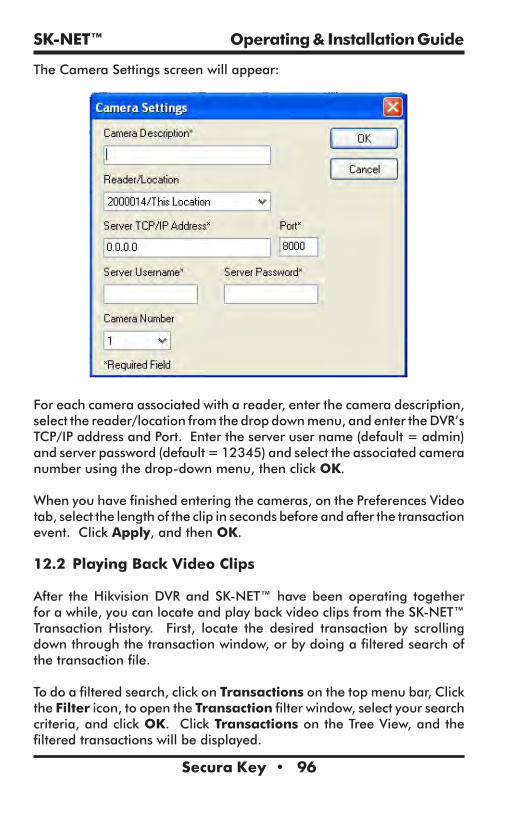
SK-NET™ Operating & Installation Guide
Secura Key • 96
The Camera Settings screen will appear:
For each camera associated with a reader, enter the camera description, select the reader/location from the drop down menu, and enter the DVR’s TCP/IP address and Port. Enter the server user name (default = admin) and server password (default = 12345) and select the associated camera number using the drop-down menu, then click OK.
When you have finished entering the cameras, on the Preferences Video tab, select the length of the clip in seconds before and after the transaction event. Click Apply, and then OK.
12.2 Playing Back Video Clips
After the Hikvision DVR and SK-NET™ have been operating together for a while, you can locate and play back video clips from the SK-NET™ Transaction History. First, locate the desired transaction by scrolling down through the transaction window, or by doing a filtered search of the transaction file.
To do a filtered search, click on Transactions on the top menu bar, Click the Filter icon, to open the Transaction filter window, select your search criteria, and click OK. Click Transactions on the Tree View, and the filtered transactions will be displayed.
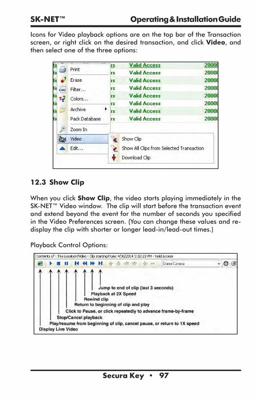
SK-NET™ Operating & Installation Guide
Secura Key • 97
Icons for Video playback options are on the top bar of the Transaction screen, or right click on the desired transaction, and click Video, and then select one of the three options:
12.3 Show Clip
When you click Show Clip, the video starts playing immediately in the SK-NET™ Video window. The clip will start before the transaction event and extend beyond the event for the number of seconds you specified in the Video Preferences screen. (You can change these values and re-display the clip with shorter or longer lead-in/lead-out times.)
Playback Control Options:

SK-NET™ Operating & Installation Guide
Secura Key • 98
12.4 Show All Clips from Selected Transaction
When you select Show All Clips, SK-NET™ will start by showing the clip for the selected transaction, and then it will continue to play all subsequent clips in a continuous sequence. This is a useful tool if you have already used the Filtering option to select all activity for a particular door or cardholder. The system displays the transaction information just above the video window while each transaction is playing. You can eliminate dead time between transactions by shortening the lead-in/lead-out time in the Video Preferences screen before you make your Video playback selection. When all the clips have played, the Video window displays “Video Clip Sequence Complete.”
12.5 Download Clip
When you choose Download Clip for the selected clip, the Save Video Clip screen opens. The default location to save clips is the Video Clips folder in the SK-NET™ directory. This screen also allows you to rename the clip and select where it will be saved on the computer, or on a removable storage device. If you rename the clip, do not change the .MP4 file extension. When the download is finished, the video window will display “Video Download Complete.”
Downloaded .MP4 clips may not play on the QuickTime or Microsoft Media Players already installed on your computer, due to special video compression methods used by Hikvision. To playback the .MP4 clips, you will need to download a free video player from Hikvision. At this time, the latest player is called VSPlayer, Version 6.2.0, but this is subject to revision, so we suggest you visit the Hikvision website for the latest version of the Video Player.
12.6 Show User Picture (Live vs. Stored Image)
The Show User Picture option allows a system operator to compare live video of a cardholder requesting access at a reader to the cardholder’s photo stored in SK-NET™ to verify the identity of the cardholder. Typically, when this feature is used, cardholders will NOT be authorized to use the reader. Once the guard verifies the person’s identity, he will use SK-NET™ to send an unlock command to the door.
To turn on the Show User Picture function, right click on any transaction and click on Show User Picture. This is a toggle function – click on it

SK-NET™ Operating & Installation Guide
Secura Key • 99
again to turn this feature off. When a card is used anywhere in the system, the cardholder photo will appear in the transaction window on the lower right side of the screen. To do the verification, the operator will click the Video Icon on the Tree View, click on the live video icon (or the video window), and use the drop down menu to select the desired camera.
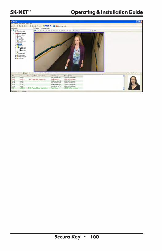
SK-NET™ Operating & Installation Guide
Secura Key • 100

SK-NET™ Operating & Installation Guide
Secura Key • 101
13.0 LOCKDOWN AND DOOR STATUS FEATURES
Security officials at Schools, Courts, Government Offices and other facilities which may be targets of crime or terrorism need to know the real-time status of controlled doors in their facility, and they also need the ability to lock or disable groups of doors with a single command in order to react to internal or external threats. This section is written primarily for School Campus Applications, but the Lockdown and Door Status Features can be used by any type of facility.
The SK-NET™ Version 5.20 (and higher) Lockdown and Door Status Features work with the Secura Key SK-ACPE-LE and the NOVA.16 (SK-MRCP) access control panels. These panels must be upgraded to the latest firmware version (see Appendix D). Legacy hardware such as SK-ACP-LE does not support the Door Status or Lockdown Features. The Door Status Feature complements the Lockdown Feature, but either Feature may be independently disabled or enabled.
Door-Status is a system-wide function. Lockdown is a Location-specific feature that is configured, activated and canceled from the Location level. In a multi-location system using SK-NET-MLD, each location can be configured, and locked down independently of any other location.
13.1 Securing Your Facility
While installing an access control system with the Lockdown and Door Status Features is a significant step toward protecting students and faculty or employees, a reputable security consultant should be contacted to analyze your facility’s physical layout and daily operations, and to develop a plan which allows the facility to be fully secured against external threats. Here are key features upon which many consultants agree:
1. Non-climbable perimeter fencing2. Video Monitoring (Secura Key offers access control integration with HIKVision VMS)
3. Door position switches and remotely controlled electric locks on all entrances and exits including gates.
4. A single point of entry for all visitors, including vendors, delivery and service people, parents and volunteers. (See Section 13.9)
a. The entrance, equipped with a video intercom, would lead into a mantrap or security vestibule constructed with ballistic glass, equipped with a metal detector and a secure pass-through window for presentation of ID or paperwork.

SK-NET™ Operating & Installation Guide
Secura Key • 102
b. Web-based applications allowing real-time checking of IDs against national terrorist, criminal and sex offender databases should be implemented.
5. Access Control and remotely-controllable classroom-type locks should be installed on all classrooms, and other areas where students congregate. Doors with “Classroom” locks open inward and can be locked from the inside of the room.
6. Strict Security Procedures: all classrooms will be locked during class. Typically, access control cards are not issued to students. All campus entrances will be staffed at the start/end of school, and are otherwise locked at all times (including evenings and weekends) to prevent pre-staging of weapons and ammunition. No one is to be ‘let in’ to the campus during the day except through the secure entrance.
7. Mobile applications: these are available to inform faculty and staff of threats and either the need for (or status of) a lockdown situation.
Lockdown Procedures and responsibilities and roles of Security Staff, Administrators, Faculty, Students or Employees, need to be clearly defined, and Lockdown drills should be conducted periodically, so that there is no question of what to do in the event of a Lockdown. Different levels of Lockdown are provided to meet the seriousness of the threat. Not every Lockdown involves an active shooter. For example, Lockdowns can be required if there is a nearby criminal on the loose, an irate parent making physical threats, an intoxicated person on campus, a tornado approaching the area, or any other number of circumstances. Security consultants can help with the development of Lockdown procedures.
13.2 Door Status
To report Door Status to the system, each controlled door requires a door position switch to be connected to an input on the SK-ACPE or Smart Reader (when using NOVA.16 panels), and the input must be enabled and defined as a Door Monitor input. The Door Monitor function is defaulted for Input #1.
When the Door status feature is enabled, SK-NET™ provides a visual display indicating the current status of all controlled doors. The system updates door status in a real-time manner, to provide users with the latest information during a crisis situation.

SK-NET™ Operating & Installation Guide
Secura Key • 103
The Door Status icon provides a general indication of the worst-case door status by changing its background color to indicate off-normal conditions: • No background color indicates that all doors are secured. • Green indicates unlocked doors (by an active remote input,
scheduled unlock or by operator unlock command) • Yellow indicates doors held too long (or propped open) • Red indicates Doors Forced Open (opened without using an
access card).
When you click on the Door Status icon, the software will show a list of doors in various states including: Door Open Remote Open Door Held Open Door Forced Open Active Normal Inactive unlocked Inactive via input Inactive Lock Need Facility Code Unlock via Door Schedule Lockdown Level 1 Lockdown Level 2 Lockdown Level 3 Valid card
Once a status condition returns to normal it will clear automatically.
13.3 Lockdown Levels
The system provides three different Lockdown levels, which offer progressively increased security – these can be selected based on the level of the threat.
Level 1 - Global Lock for Lockdown Group• Indefinitely cancels all Manual or Door Zone unlock commands.• Re-locks all doors that are physically closed, but unlocked by the system.
• A valid card will still unlock any controlled door. • An Override Card will also unlock any door including those which are inactive due to an operator command or a remote inactive input.

SK-NET™ Operating & Installation Guide
Secura Key • 104
Level 2 - Global Inactive for Lockdown Group • Indefinitely cancels all Manual or Door Zone unlock commands • Relocks all doors that are physically closed, but unlocked by the system
• Places all doors in inactive mode – this disables all valid cards, preventing an intruder from using a stolen card. Note that the reader LEDs do not blink red as they do normally, when readers are placed in inactive mode and lockdown is not in effect.
• Override cards (section 13.4) will work on all inactive doors (if otherwise properly programmed).
Level 3 - Global Lockdown for Lockdown Group• Indefinitely cancels all Manual or Door Zone unlock commands. • Relocks all doors that are physically closed, but unlocked by the system.
• Places all doors in inactive mode – this disables all valid cards, preventing an intruder from using a stolen card.
• Override cards (section 13.4) will work on all inactive doors (if otherwise properly programmed).
• Disables all REX or ‘remote open’ inputs, preventing students or faculty from exiting a secure area without authorization.
• This may conflict with fire safety regulations, so check with local authorities having jurisdiction before implementing Level 3. (Some authorities may allow this restriction in a crisis situation.)
13.4 Lockdown Override Cards
During a Level 2 or 3 Lockdown, the general ability to use the access control system is disabled, to avoid giving access to an assailant using a stolen card or forcing a cardholder to unlock doors. Even the REX (remote open) function is disabled in Level 3.
However, campus police, or local authorities can be issued credentials which will override the lockdown at any individual reader (this will not affect the overall lockdown), allowing them to move around the campus in order to capture or neutralize an assailant. Cards assigned to the Lockdown Override Range and the Override Access Group (section 13.5) would be granted access at any functional reader connected to the system, regardless of whether the reader was inactive or locked.

SK-NET™ Operating & Installation Guide
Secura Key • 105
13.5 Configuring and Enabling the Lockdown Feature
It is recommended that you create a special Lockdown Reader Group containing all the readers/doors that need to be relocked or disabled as needed during a Lockdown.
1. Right-click on Location, New, Reader Group, 2. Name the group and add readers by the drag-and-drop method.
To set the default Lockdown settings and enable the Lockdown Feature:1. Right-click on Location, Properties, and the Lockdown Tab to set the default Lockdown settings (used automatically when the Lockdown icon is clicked).
2. Click on the checkbox for Turn On Lockdown Feature.3. The system will prompt to remind you that the latest control panel firmware is required. If you have the latest firmware, click OK to proceed (if not see Appendix D of this manual).
4. Select the Lockdown Level (see section 13.4). 5. Select the default Lockdown Reader Group 6. Enter Starting and Ending ID numbers for the Override Card Range – cards in this range will be issued to First Responders and School Security Officers, allowing them to override inactive readers in any Lockdown Level.
7. Click on Close.

SK-NET™ Operating & Installation Guide
Secura Key • 106
It is recommended that an Override Access Group be created, which includes all the readers in the system, as well as the Master Time Zone (Time Zone 1, 24-hour-7-day access). To create the Override Access Group:
1. From the tree view, right click on Location, then on the drop-down menu click New, then Access Group. Type Override Access Grp into the name field, and type 01 into the Time Zone field, then click OK.
2. From the tree view, right-click the new Override Access Grp, click Properties, then click the Readers Tab, click Add All, then Close.
Assign Override Cards to the Override Access Group: 1. Click on Location, Users, then right-click anywhere in the user list and select Modify from the drop-down menu, then click on Range.
2. The Modify Card Range screen appears: enter the Start and End card ID numbers for the Override Range, then click on the dropdown field next to Access Group and select the Override Access Group, then click OK.
3. On the top menu bar, click on Send Users Full.
13.6 Configuring and Enabling the Door Status Feature
1. In the top menu bar, click on File, Preferences, and Door Status.2. Click the checkbox for Turn On Door Status Feature. 3. The system is provided with default colors for the Door Status display text. However, you can make any desired changes to text color and fonts for the various transactions. The Defaults button returns all door status types to their default colors if you want to cancel any changes that have been made.

SK-NET™ Operating & Installation Guide
Secura Key • 107
4. Click Apply and OK to make the changes.
13.7 Using the Lockdown Feature
1. In the event of a reported threat, click on the Lockdown icon on the top menu bar.
2. A window will appear, with the default lockdown level pre-selected. You can go with the preselected level, by clicking OK or you can change the Lockdown Level at this point and then click OK.

SK-NET™ Operating & Installation Guide
Secura Key • 108
3. The system will display a confirmation prompt (click Yes to proceed) and a Lockdown Started prompt (click OK). Then the Lockdown Icon will indicate the Lockdown Level, and the Door Status screen will show the current door status. A Lockdown Transaction will be logged in the Transaction History showing the level, where originated, and the time and date.
If any doors are in a non-secure state when you initiate the lockdown, The Door Status icon will flash in the appropriate color, indicating that the lockdown is incomplete. Take the appropriate action, according to your Lockdown security plan.
13.8 Canceling the Lockdown
1. To cancel a lockdown, click on the Lockdown button and the following prompt will appear:
2. Click on Yes to cancel the Lockdown. The Door Status display will be updated when the Lockdown is cancelled. A Lockdown Cancelled Transaction will be logged in the Transaction History showing the time and date, the lockdown level, and where the command originated (PC).

SK-NET™ Operating & Installation Guide
Secura Key • 109
If School Security officials or First Responders determine that a particular building is safe to evacuate during a Lockdown event, Override Cards can be used to unlock controlled doors and extract students and faculty from a Lockdown area.
13.9 Mantrap Entrance
Most campus security consultants recommend a single highly-secure entrance for all visitors, using a Mantrap configuration. This entrance does not actually require the Lockdown/Door Status Feature, but it is a key component of a secure campus. This can be easily accomplished using a NOVA.16 control panel and two Smart Readers, or an SK-ACPE-LE 2-door control panel with two wiegand output readers.
The incoming side of the Mantrap would be constructed similarly to a typical Bank entrance mantrap with one door entering from the outside into the vestibule (equipped with a video intercom unit, such as Aiphone JB2HD adjacent to the entry door and a release button located in the secure area) and a second door inside the vestibule exiting into the secure area. The mantrap would be constructed with ballistic glass, and a pass-through window inside the vestibule would allow the person to present their ID to security for verification.
Door monitor switches would be wired in series and then connected to an input controlling a relay, such that both doors need to be closed to either unlock the entrance door to the mantrap or to unlock the door leading into the secure area.
A reader is installed at the outside entrance to the vestibule, as well as inside the vestibule at the exit to the secure area. Most visitors will not be cardholders (at least until they are authorized and issued a badge), so school officials will need to use a video intercom and momentary pushbuttons inside the secure area to admit visitors to the mantrap and subsequently to allow them into the secure area following inspection of their ID and scanning by the metal detector.
The relay output of a metal detector such as CEIA 02PN8 HI-PE/CF can be wired in series with the remote open input, as well as with the arming circuit for the interior reader. A positive indication at the metal detector would interrupt the arming and REX circuits, preventing the visitor from exiting the vestibule into the secure area.

SK-NET™ Operating & Installation Guide
Secura Key • 110
The outgoing side of the Mantrap would be much simpler, consisting of a similarly built vestibule with interlocking doors. No release buttons, readers, or metal detectors are needed. The exit doors leading to the outside, are always locked from the outside. Once a person enters the vestibule from the secure area, the door locks behind the person, and the exit door is unlocked.
METAL DETECTOR READER
ENTRY DOOR
CARD READER
VIDEO INTERCOM
OUTSIDE SECURE AREA
CARD READER
ADMINISTRATIVE OFFICE AREA
EXIT TO CAMPUS
EXIT DOOR
SECURITY OFFICEDOOR RELEASE
BUTTONS PASS THROUGHWINDOW
SAMPLE MANTRAP DIAGRAM
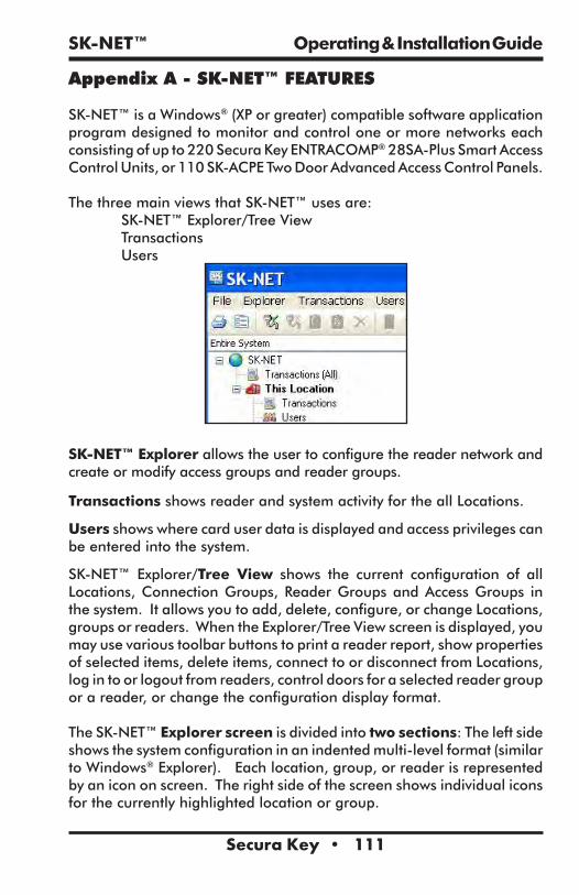
SK-NET™ Operating & Installation Guide
Secura Key • 111
Appendix A - SK-NET™ FEATURES
SK-NET™ is a Windows® (XP or greater) compatible software application program designed to monitor and control one or more networks each consisting of up to 220 Secura Key ENTRACOMP® 28SA-Plus Smart Access Control Units, or 110 SK-ACPE Two Door Advanced Access Control Panels.
The three main views that SK-NET™ uses are: SK-NET™ Explorer/Tree View Transactions Users
SK-NET™ Explorer allows the user to configure the reader network and create or modify access groups and reader groups.
Transactions shows reader and system activity for the all Locations.
Users shows where card user data is displayed and access privileges can be entered into the system.
SK-NET™ Explorer/Tree View shows the current configuration of all Locations, Connection Groups, Reader Groups and Access Groups in the system. It allows you to add, delete, configure, or change Locations, groups or readers. When the Explorer/Tree View screen is displayed, you may use various toolbar buttons to print a reader report, show properties of selected items, delete items, connect to or disconnect from Locations, log in to or logout from readers, control doors for a selected reader group or a reader, or change the configuration display format.
The SK-NET™ Explorer screen is divided into two sections: The left side shows the system configuration in an indented multi-level format (similar to Windows® Explorer). Each location, group, or reader is represented by an icon on screen. The right side of the screen shows individual icons for the currently highlighted location or group.

SK-NET™ Operating & Installation Guide
Secura Key • 112
The highest level in the Explorer Tree View configuration window is SK-NET™ (the entire system) which includes all locations, groups, and readers controlled from the PC being used.
The second highest level is Location. A location includes all readers on a single network connected to the PC via a single COM port, TCP/IP address or a single modem location. Each Location can contain up to 128 28SA-PLUS units or 100 SK-ACPE two-door panels. A red triangle adjacent to the Location icon indicates that you are connected to that Location. Green check marks next to individual reader icons indicate that you are “logged in” to those readers. Being logged in means that transactions stored in the reader have been copied into the software and that you may view transactions as they occur in the Transaction screen.
The third level in the system is Groups. Each Location contains four default Groups: IN and OUT Readers, Master Users and Void Users.
Connection Groups define a means to access a reader gateway. They contain all readers that are visible through the reader gateway via RS-232, LAN connection or by modem. In the Multiple Location and Client/Server systems, more than one Connection Group can be created and connected simultaneously by connecting the Locations.
Because readers can belong to multiple groups, you will see the same icon appearing several times in the system configuration display.
To expand SK-NET™, a Location, or a Group to the detail level, click on the “+” icon just to the left of the item you want to expand. The “+” icon changes to “-“ when it is expanded. If there is no “+” or “-“ icon next to a Location or Group that indicates that nothing has been assigned to that Location or Group.
The Transaction View shows the latest system events as they occur, for the Location which is currently connected to SK-NET™.
System events include card usage, input point status changes, reader status changes, and system messages.
Each event is displayed on a single line, and includes the time and date of the event, card number (for card transactions), User Name (if the

SK-NET™ Operating & Installation Guide
Secura Key • 113
name is stored in the database), Transaction Type (what happened), and Reader ID/Location (name of the reader and the Location to which the reader is connected).
The Transaction Window allows you to view the entire Transaction Database, by using the navigation buttons or the scroll bar to browse through the transaction records.
Transaction Database options include Print Transaction Reports, Erase, Change Colors, and Zoom In.
The Transaction Window normally shows data for all Locations (when filtering is not applied). Whenever SK-NET™ connects to a Location, all new transactions stored at the readers are automatically uploaded.
The User View allows you to display or change the Card User Database. You can add new card users or edit current user records. You may use the scroll bar or navigation buttons to view the entire Card User Database. You can also print user reports, search for an individual user, or optionally, select user databases for multiple locations.
The User View defaults to a List format, one line per record. If you click on Zoom, the User Detail Screen is displayed for the currently selected user. You can also select a user from the list and double-click to display the record in User Detail format. Editing or adding cards is done by displaying the User Detail screen. The Navigation buttons work in either List or User Detail format.

SK-NET™ Operating & Installation Guide
Secura Key • 114
Appendix B - WORKING IN WINDOWS
SK-NET™ uses many common functions available in Windows®. For users who are new to Windows® software these are the functions you will need to know to use SK-NET™.
ICONS and TOOL BARS:Icons are little pictures that represent functions or files in the software. Most of the operations you will perform in SK-NET™ begin by pointing at and clicking on an icon. Most icons in SK-NET™ will display a “prompt”, a word description of the icon, when you point the cursor at it.
Toolbars appear at the top and on the left side of each screen in SK-NET™. Toolbars contain icons that allow you to perform functions or open files in the program. The topmost toolbar will be comprised of words. Clicking on these words brings “drop-down menus” listing functions that you may select.
MOUSE BUTTONS:When we direct you to “CLICK” on something, we mean that you move your cursor with the mouse to point at that item and then you tap the left button on the mouse once. This is usually done to select or highlight an item. When we tell you to “DOUBLE CLICK”, the only difference is that you tap on the left button twice in rapid succession. This is usually done to launch a program or to start a function.
When we tell you to “RIGHT CLICK”, tap on the right mouse button once. This is used to bring up a menu box that pertains to the item you are pointing at.
When we tell you to “DRAG-AND-DROP” you first point the cursor at the item, then hold down the left mouse button and, while holding that button down, move the cursor to the location where you want to “drop” the item you are “dragging”. When the item is in the new location, release the left mouse button to “drop” it. We use drag-and-drop in the Explorer screen to make it easy for you to add individual readers to access groups and hardware groups.
EXPLORER:One of the principal screens in SK-NET™ is SK-NET EXPLORER. This view is modeled after the well-known Windows® Explorer. On the left-hand side of the screen you will see all of the elements of your system in a
SK-NET™ Operating & Installation Guide
Secura Key • 115
“tree” format. If an item in the tree has a plus (+) or minus (-) symbol next to it, it represents a folder. Clicking on the + symbol “opens” that folder and displays what is inside. For example, the folder called “New Connection1” may contain an icon for every reader in the system. Clicking on the + symbol next to the New Connection1 icon will display icons for each reader, underneath the New Connection1 heading.
On the right-hand side of the screen you will see icons representing whichever part of the Explorer tree you have highlighted. For, example, if you CLICK on New Connection1, the right-hand side of the screen will display one icon for every reader in that Connection Group.
HELP:SK-NET™ has extensive help, which you can access by clicking on Help on the top menu bar, or by pressing F1. Much of the information in this manual is also included in the on-line Help System.
To learn more about the functions of various icons or “buttons”, click on Help or press F1, select Contents, Getting Started, then SK-NETTM Desktop. Pressing F1 in the main windows (Explorer, Transactions or User Manager) also offers context-specific help for those screens.

SK-NET™ Operating & Installation Guide
Secura Key • 116
Appendix C - USING SECURA KEY LAN INSTALLER
Secura Key LAN Installer is a utility supplied with the SK-NET™ software. It is not part of the SK-NET™ program, but it can be found on the USB flash drive that also includes SK-NET™.
Secura Key LAN Installer allows you to configure or update IP addresses in SK-ACPE or SK-MRCP (NOVA.16) control panels over the network. You do not have to make a direct connection to each panel to load the IP addresses. IP Addresses and Gateway port will be provided by your IT Manager. These will include:
TCP/IP addressSubnet MaskDefault GatewayDNS ServerGateway Port (Defaults to 10001 in SK-NET)
Make note of the serial number of each panel that you are configuring - you will need to know this when using Secura Key LAN Installer. The control panel serial number (SER 1234567) is printed on a sticker which is affixed directly to the printed circuit board assembly (MRCP - on top of the two large filter capacitors, SK-ACPE – on top of the black Latch relay).
To configure a control panel, simply connect it to your local area network using the onboard RJ-45 jack. At the host computer, launch Secura Key LAN Installer by locating the Secura Key LAN Installer file on the flash drive and double-clicking the SKLANInstaller.exe’ file. The PC will display the following screen:

SK-NET™ Operating & Installation Guide
Secura Key • 117
With the values for the settings provided by your IT Manager, you may simply follow the four-step instructions shown on the Configure page.
You can also configure your panels from the View All screen. 1. Click Find, and the system will display all the panels on the network. 2. Click the Check Box for the serial number of the panel you
wish to configure, 3. Click Edit. 4. Enter the TCP/IP Addresses supplied by your IT department, 5. Click Send. 6. When the system prompts “Send Parameters Now?” Click
OK, then click OK again for Parameters Sent.

SK-NET™ Operating & Installation Guide
Secura Key • 118
Appendix D - ADVANCED SETTINGS
The Advanced Settings Screen allows you to view or change TCP/IP settings and Gateway Port of an SK-ACPE or NOVA.16 Control Panel, to disable UDP Antipassback Broadcasts, to turn RS-485 Network Biasing on or off, or to download new control panel firmware. To access this screen through the Reader Properties menu of an associated reader:
1. From the Tree View, right click on the Reader Name2. Click on Properties 3. Click the Settings Tab4. Click the Advanced Button
TCP/IP Settings - allows you to view or change TCP/IP Settings and Gateway IP Port and Disable UDP Antipassback Broadcasts for the associated control panel. TCP/IP Settings are originally configured using SK-NET LAN Installer, SK-NET Utility, or Hyperterm, when each panel is initially configured for TCP/IP communications. The Gateway IP Port defaults to 10001, but can be changed if there are port conflicts on the network.
There is also an option to Disable UDP Antipassback Broadcasts – For SK-NET™ systems where the control panels are connected via the Local Area Network, SK-NET™ uses User Datagram Protocol (UDP) broadcasts to update cardholder Antipassback (IN or OUT) status and Limited Use status to all panels on the network. If UDP broadcasts create conflicts, or are not permitted on the network, they can be disabled for the associated panel, in which case Antipassback and Limited Use status will not be updated. To completely disable UDP Broadcasts, this feature must be disabled on every control panel in the network.
To enter new settings:1. Click Edit 2. Make the required parameter changes.3. Click Send to send the new settings to the panel, or Cancel to
leave the current settings in place. Click Refresh to undo any changes you have made.
RS-485 Network Biasing – these settings allow you to turn on RS485 end-of-line resistors at the Smart Reader or at the associated control panel. There are potentially two RS-485 networks in a system with NOVA.16 panels and smart readers:
The Command Bus - the RS-485 network connecting one or more panels
The Peripheral Bus – the RS-485 network of up to 16 readers connected to a single panel (NOVA.16 Only)

SK-NET™ Operating & Installation Guide
Secura Key • 119
RS-485 Network Biasing can also be configured for SK-ACPE panels. The configuration screen is identical, except that there is no check box for the Peripheral Bus.
As your system approaches the maximum RS-485 cable distance of 4000 feet, signal reflections on the bus due to the long cable may interfere with communications. To damp these signal reflections, a resistor equal to the line impedance is placed at the end of the bus. Secura Key Control Panels and Smart Readers have this resistor built-in and switchable through the software, so you do not have to physically install resistors at the end of the cables.
If your Command Bus has very long RS-485 cables, turn the Command Bus bias resistor ON at the furthest panel from the PC by editing Advanced Settings for any reader on that panel. If the Peripheral Bus connected to any NOVA.16 panel has very long RS-485 cables, turn the Peripheral Bus Bias resistor ON by editing Advanced Settings for the farthest reader from the control panel.
Only turn on ONE EOL resistor on an RS-485 bus, and ONLY at the end of the bus.
To enter new settings:1. Click Edit (for RS-485 Network Biasing)2. Click the appropriate Check Box(es), 3. Click Send to send the new settings to the panel, or Cancel to
leave the current settings in place. Click Refresh to undo any changes you have made.

SK-NET™ Operating & Installation Guide
Secura Key • 120
The Advanced Settings screen also allows you to update the firmware in the associated NOVA.16 panel or SK-ACPE panel, if the firmware has been downloaded to the PC, the SK-MRCP button will be enabled
1. Click the SK-MRCP Button to download the firmware2. Follow the prompts.
Smart Reader firmware downloads are not available in Version 5.1 but are planned for future use.

SK-NET™ Operating & Installation Guide
Secura Key • 121
SK-NET™ - GLOSSARYAccess Group – A set of cardholders who are valid at the same readers and have the same time zone restrictions. Groups are ideal for multi-departmental facilities with different time schedules. Section 5.14
Block Of Cards – A contiguous group of cards in sequential card-number order. Section 3.5
Connection Group – Connection Groups define a means to access a reader gateway. It contains all readers that are visible through the reader gateway via RS-232, LAN connection or by modem. See Appendix A.
Connection Wizard – A special function where SK-NET software automatically goes through the various COM ports and baud rates on your system to make a connection. This function can be found by right-clicking a Location, selecting Properties, choosing the Connection tab, then clicking on the Connection Wizard icon. NOTE: The conncetion wizard can now search for LAN connections. Section 3.2
Door Controls – A group of commands that affect the door or gate at a connected location. Door controls can be initiated in real time, using the SK-NET software. The system operator has the capability of controlling whether is a door is unlocked or locked, and whether the reader is inactive or active. Section 5.30
Door Schedule – A time zone that is specifically assigned to a door, which causes the door to automatically lock and unlock according to a regular weekly time schedule. Section 5.18
Hardware Password – The default password for your SK-ACPE or 28SA Plus reader is “12345”. Section 8.4
Holidays – The system operator can enter up to 32 holidays that will use the Holiday Schedule in the system time zones, instead of the normal schedule for the day of the week. This allows access to be restricted or different than normal on Holidays. Section 5.20
“IN” / “OUT” Readers – When a room or area has readers on both sides of each door to control both entry and exit, the readers controlling entry can be assigned to an IN group, and readers controlling exit can be assigned to an OUT group. This allows the access control system to track the status of each cardholder to determine if the cardholder is IN or OUT of the area. It also allows the system to control the cardholder’s direction of movement and to prevent card passback by invoking the Anti-Passback feature, which prevents an IN or OUT reader from being used twice in succession by the same cardholder. Section 5.25

SK-NET™ Operating & Installation Guide
Secura Key • 122
Inputs – These are circuits that connect external sensors or switches to an SK-ACPE or 28SA-Plus or a Smart Reader used with NOVA.16. Status changes on these circuits can initiate special functions or generate messages in the transactions screen. Various input types can be defined, including Tamper, Arming (loop detector), door monitor, request-to-exit (remote open), Bell, Remote Inactive (disable reader), and User Defined. Section 5.31
Limited Use Cards – Any card can be defined to have this feature. These cards are valid for a specific number of uses, days or weeks. After the preset limit is reached, the cards become void. Limited use cards can be defined for a single location or a single reader. Section 5.8
Location – A location is a group SK-ACPE or NOVA.16 panels (and connected readers) or 28SA-Plus readers networked together via RS-485 and operating as a unified system. Section 4
Output (Relay) – Relays are electromagnetically controlled switches located on the SK-ACPE control panel. Smart Readers connected to NOVA.16 panels have two open-collector outputs which can be connected to relays. When actuated, relays complete power circuits connecting external devices and their external power supplies, operating door strikes, gate actuators, and annunciators (horns, bells, or flashers). The SK-ACPE has a latch relay and an auxiliary relay. The latch or access relay is actuated when a card access request is granted. The auxiliary relay can be configured to activate for various conditions such as emulating the status of an input, or for an alarm condition such as door-held, door-forced, emergency exit, error alarm, tamper alarm, or a card transaction in a specified range, etc. Section 5.33
Reader Group - A set of readers created for the purpose of defining common properties for those readers. Section 5.28
Real Antipassback (RAPB) – This feature can be assigned to a Time Zone, and it controls cardholder movement using designated IN or OUT readers. If a card was last used at an IN reader, it must be used at an OUT reader before it will be valid at an IN reader again. This feature was originally developed for parking garages to prevent an authorized cardholder from passing his card back to an unauthorized user after entering the lot. Section 5.9
Real Antipassback Forgive – This command resets all cards to a neutral in/out status, allowing the next card use at either an IN or OUT reader. It can be invoked for all readers or for a specific reader. It can be scheduled to occur daily at a specified time (usually early in the morning) or it can be manually invoked for all cardholders, a specific cardholder number range, or for a single cardholder. Section 5.10

SK-NET™ Operating & Installation Guide
Secura Key • 123
Renaming Readers – After SK-NET™ initially locates readers, it assigns the default name for the readers, which is usually the serial number with a dash one or dash two indicating connection to the right or left hand reader input. It is recommended that the system operator “rename” their readers with a meaningful name (such as their physical location) to better identify them when doing maintenance. Section 3.3
SK-NET-DM – This version of SK-NET™ is primarily used for a “direct connect” from the access control system to the COM port on a single computer. A single TCP/IP connection is also allowed. Section 1.2
SK-NET-MLD – This version of SK-NET™ is needed when there are multiple locations, and some locations are connected to the computer using a modem or a LAN adapter. It is required for multiple TCP/IP connections. It also includes badge printing capabilities. Section 1.2
SK-NET-MLD- CSXX – This is the Client/Server version of SK-NET™, which is used when there are multiple locations, and more than one user needs to access the database simultaneously. The SK-NET™ database is loaded on a Server computer, and multiple Client Workstations can access the Server on the same network. Client/Server licenses can be purchased for 2, 5, 10, or 15 workstations. Section 1.2
Software Password – Upon opening the SK-NET™ software, you will be prompted to enter a username and password. The default username when first opening the software is “admin”, and the password is “12345”. Section 3.1
Timed Antipassback (TAPB) – This feature must be assigned to a Time Zone 2 to 15. After a card is used at a reader with Timed Antipassback, that card will not be valid at that reader for a predetermined amount of time. Section 5.8
Time Zone – A schedule that determines which days of the week and hours of the day that a cardholder can obtain access at an associated door. Each weekday is divided into 48 half-hour segments that can be defined as Void or Valid for access by the system operator. A Holiday time schedule can also be defined for each Time Zone (see Holiday). Section 5.2
Transactions – These are various system events, such as cardholder access granted/denied, alarm status changes, power failures, door lock/unlock commands, etc., which are stored in transaction history with the time and date that they occurred. Reports can be printed and saved in either .pdf or .xls format. Section 7

SK-NET™ Operating & Installation Guide
Secura Key • 124
SYSTEM COMPONENTSPANELSSK-ACPE-LE Large enclosureSK-ACPE-NE No enclosure (board only)SK-MRCP-LE NOVA.16-control panel, large enclosureSK-MRCP-NE NOVA.16-control panel, no enclosureSK-MRCP-PCBA NOVA.16-control panel, no enclosure, no connectors
SOFTWARESK-NET-DM Basic SK-NET™ with Disk & ManualSK-NET-MLD SK-NET™ w/ Multi-Location, Dial-Up and multiple TCP/IP
Communications, For 1 User, includes ID Badge Printing CapabilitySK-NET-MLD-C/S Multiple User Workstations, Multiple Locations via Dial-Up
Modem and Multiple TCP/IP Communications (2, 5, 10, 15 user licenses available)
ACCESSORIESNET-CONV-P: RS232 to RS485 converter with power supply SK-MDM: External 56K modemSK-LAN-MOD: Network Adapter, plug-in for SK-ACPs (not required for SK-ACPE)SK-WLSE-MOD: Wireless LAN Adapter, plug-in for SK-ACPE, SK-MRCPSK-PLUG9: DB9 female computer connector SK-USB: USB to RS-232 converter for computers without COM ports SK-LOCK: Optional lock and keys for SK-ACPE enclosureSK-ACP-PS: Power supply kit including 24VDC supply & 4.0 AH battery SK-24VDC: 24VDC, 1A plug-in power supply SK-XFRMR: 16.5 VAC, 40VA plug-in transformer w/ground DTK-XR: Surge protection for power, data and phone lines DTK-CR: Surge protection for card readers and keypads SK-BAT: 4.0AH – 12VDC battery onlyRS-232E Serial cable for use with laptop computer DB9 to 4 Pin MTA
Connection for SK-ACPE and SK-MRCPREADERS FOR SK-ACP(E)RK-WM Proximity Reader, MullionRK-WS Proximity Reader, SwitchplateRK-WL Proximity Reader, 12” X 12”RKDT-WM Proximity Reader (Radio Key®/HID®), MullionRKDT-WS Proximity Reader (Radio Key®/HID®), SwitchplateET4-WXM e*Tag® Contactless Smart Card Reader, MullionET4-WXS e*Tag® Contactless Smart Card Reader, SwitchplateET8-RO-W-D-W e*Tag® Contactless Smart Card Reader, Decorator (Indoor)ET8-RO-W-D-I e*Tag® Contactless Smart Card Reader, Decorator (Indoor)ET8-RO-W-M e*Tag® Contactless Smart Card Reader, Mullion, ET9-RO-W-MR e*Tag® Contactless Smart Card Reader, Mid-range
READERS FOR NOVA.16 (SK-MRCP)ET8-SR-X-M e*Tag® Contactless Technology, mullion,ET8-SR-X-D-I e*Tag® Contactless Technology, switchplate, Decorator (indoor)ET8-SR-X-D-W e*Tag® Contactless Technology, switchplate, Decorator (indoor)
RKDT-SR-M Radio Key® & HID® Proximity, mullionRKDT-SR-S Radio Key® & HID® Proximity, switchplate
