sk714,815-5 #01876-00902_webm005501_u0502 (1)
TRANSCRIPT

����������
���
�������
����
��������� � � � � � ���� ��� � ���� ��� � ���� ��� � �����
���������
��� ������ ������ ������������������� ��������� ������
��� ��������� ��� ��������
��� ������ ���!�" ��������
��� ���� �������� ����""� ��������


����������
���������
��� ������ ������ ������������������� ���������� �����
��� ���� ������ ��� ��� ��
��� ���� ��� ���!�" ��� ��
��� ���� ������ ��� ����""� ��� ��
SK714-5 SK815-5 SK815-5 turbo 00-1

CONTENTS
CONTENTS
Page
10 STRUCTURE AND FUNCTION........................................................................................ 10-1
20 TESTING AND ADJUSTING............................................................................................. 20-1
30 DISASSEMBLY AND ASSEMBLY .................................................................................. 30-1
40 MAINTENANCE STANDARD ........................................................................................... 40-1
SK714-5 SK815-5 SK815-5 turbo00-2

The affected pages are indicated by the use of the following marks. It is requested that necessary ac-tions be taken to these pages according to table be-low.
Pages having no marks are those previously revised or made additions.
Mark Indication Action required
❍ Page to be newly Add
● Page to be replaced Replace
( ) Page to be delete Discard
LIST OF REVISED PAGES
Mark Page Time of revision Mark Page Time of
revision Mark Page Time of revision Mark Page Time of
revision Mark Page Time of revision
00-100-200-2-100-2-200-300-400-500-600-700-800-900-1000-1100-1200-1300-1400-1500-1600-1700-1800-1900-2000-2100-22
10-110-210-310-410-510-610-710-810-910-1010-1110-1210-1310-1410-1510-16
10-1710-1810-1910-2010-2110-2210-2310-2410-2510-2610-2710-2810-2910-3010-3110-3210-3310-3410-3510-3610-3710-3810-3910-4010-4110-4210-4310-4410-4510-4610-4710-4810-4910-5010-5110-5210-5310-5410-5510-5610-57
10-5810-5910-6010-6110-6210-6310-6410-6510-6610-6710-6810-6910-7010-7110-7210-7310-7410-7510-7610-7710-7810-7910-8010-8110-8210-8310-8410-8510-8610-8710-8810-8910-9010-9110-9210-9310-9410-9510-9610-9710-98
10-9910-10010-10110-10210-10310-10410-10510-10610-10710-10810-10910-110
20-120-220-320-420-520-620-720-820-920-1020-1120-1220-1320-1420-1520-1620-1720-1820-1920-2020-2120-2220-2320-2420-2520-2620-2720-28
20-2920-3020-3120-3220-3420-3520-3620-3720-3820-3920-4020-4120-42
30-130-230-330-430-530-630-730-830-930-1030-1130-1230-1330-1430-1530-1630-1730-1830-1930-2030-2130-2230-2330-2430-2530-2630-27
SK714-5 SK815-5 SK815-5 turbo
REVISED PAGES
00-2-1

Mark Page Time of revision Mark Page Time of
revision Mark Page Time of revision Mark Page Time of
revision Mark Page Time of revision
30-2830-2930-3030-3130-3230-3330-3430-3530-3630-3730-3830-3930-4030-4130-4230-4330-4430-4530-4630-4730-4830-4930-5030-5130-5230-5330-5430-5530-5630-5730-5830-5930-6030-6130-6230-6330-6430-6530-6630-6730-68
40-140-240-340-440-540-640-740-840-940-1040-1140-1240-1340-1440-1540-1640-1740-18
40-1940-2040-2140-22
REVISED PAGES
SK714-5 SK815-5 SK815-5 turbo00-2-2

SAFETY
IMPORTANT SAFETY NOTICEProper service and repair is extremely important for the safe operation of your machine. The service and repair techniques recommended by Komatsu Utility and describe in this manual are both ef-fective and safe methods of operation. Some of these operations require the use of tools specially designed by Komatsu Utility for the purpose.To prevent injury to workers, the symbols and are used to mark safety precautions in this manual. The cautions accompanying these symbols should always be carefully followed. If any danger arises or may possibly arise, first consider safety, and take necessary steps to face.
SAFETYGENERAL PRECAUTIONSMistakes in operation extremely dangerous. Read all the Operation and Maintenance Manual care-fully BEFORE operating the machine.
1. Before carrying out any greasing or repairs, read all the precautions written on the decals which are suck on the machine.
2. When carrying out any operation, always wear safe-ty shoes and helmet. Do not wear loose work clothes, or clothes with buttons missing.• Always wear safety glasses when hitting parts
with a hammer.• Always wear safety glasses when grinding
parts with a grinder, etc.
3. If welding repairs are needed, always have a trained, experienced welder carry out the work. When carrying out welding work, always wear weld-ing gloves, apron, glasses, cap and other clothes suited for welding work.
4. When carrying out any operation with two or more workers, always agree on the operating procedure before starting. Always inform your fellow workers before starting any step of the operation. Before starting work, hang UNDER REPAIR signs on the controls in the operator’s compartment.
5. Keep all tools in good condition and learn the correct way to use them.
6. Decide a place in the repair workshop to keep tools and removed parts. Always keep the tools and parts in their correct places. Always keep the work area clean and make sure that there is no dirt or oil on the floor. Smoke only in the areas provided for smoking. Nev-er smoke while working.
PREPARATIONS FOR WORK 7. Before adding or making any repairs, park the ma-
chine on hard, level ground, and block the wheels to prevent the machine from moving.
8. Before starting work, lower outrigger, bucket or any other work equipment to the ground. If this is not possible, use blocks to prevent the work equipment from falling down. In addition, be sure to lock all the control levers and hang warning sign on them.
9. When disassembling or assembling, support the machine with blocks, jacks or stands before starting work.
10. Remove all mud and oil from the steps or other plac-es used to get on and off the machine. Always use the handrails, ladders or steps when getting on or off the machine. Never jump on or off the machine. If it is impossible to use the handrails, ladders or steps, use a stand to provide safe footing.
PRECAUTIONS DURING WORK11. When removing the oil filler cap, drain plug or hy-
draulic pressure measuring plugs, loosen them slowly to prevent the oil from spurting out. Before disconnecting or removing components of the hydraulic circuit and engine cooling circuit, first remove the pressure completely from the circuit.
12. The water and oil in the circuits are not hot when the engine in stopped, so be careful not to get burned. Wait for the oil water to cool before carrying out any work on the cooling water circuits.
13. Before starting work, remove the leads from the bat-tery. Always remove the lead from the negative ( – ) terminal first.
SK714-5 SK815-5 SK815-5 turbo 00-3
SAFETY
14. When raising heavy components, use a hoist or 19. Be sure to assemble all parts again in their original
crane. Check that the wire rope, chains and hooks are free from damage. Always use lifting equipment which has ample ca-pacity. Install the lifting equipment at the correct places. Use a hoist or crane and operate slowly to prevent the component from hitting any other part. Do not work with any part still raised by the hoist or crane.15. When removing covers which are under internal pressure or under pressure from a spring, always leave two bolts in position on opposite sides. Slowly release the pressure, then slowly loosen the bolts to remove.
16. When removing components, be careful not to break or damage the wiring. Damage wiring may cause electrical fires.
17. When removing piping, stop the fuel or oil from spill-ing out. If any fuel or oil drips on to the floor, wipe it up immediately. Fuel or oil on the floor can cause you to slip, or can even start fires.
18. As a general rule, do not use gasoline to wash parts. In particular, use only the minimum of gasoline when washing electrical parts.
places. Replace any damage parts with new parts. When installing hoses and wires, be sure that they will not be damaged by contact with other parts when the machine is being operated.
20. When installing high pressure hoses, make sure that they are not twisted. Damaged tubes are dan-gerous, so be extremely careful when installing tubes for high pressure circuits. Also, check that connecting parts are correctly tightened.
21. When assembling or installing parts, always use specified tightening torques. When installing the parts which vibrate violently or rotate at high speed, be particulary careful to check that they are correctly installed.
22. When aligning two holes, never insert your fingers or hand.
23. When measuring hydraulic pressure, check that the measuring tool is correctly assembled before taking any measurement.
24. Take sure when removing or installing wheels.
SK714-5 SK815-5 SK815-5 turbo00-4

FOREWORDThis shop manual has been prepared as an aid to improve the quality of repairs by giving the operator an accurate
understanding of the product and by showing him the correct way to perform repairs and make judgements. Make sure you understand the contents of this manual and use it to full effect at every opportunity.
This shop manual mainly contains the necessary technical information for operations performed in a service work-shop.
The manual is divided into chapters on each main group of components; these chapters are further divided into the following sections.
STRUCTURE AND FUNCTIONThis section explains the structure and function of each component. It serves not only to give an understanding of the structure, but also serves as reference material for troubleshooting.
TESTING AND ADJUSTINGThis sections explains checks to be made before and after performing repairs, as well as adjustments to be made at completion of the checks and repairs. Troubleshooting charts correlating «Problems» to «Causes» are also included in this section.
DISASSEMBLY AND ASSEMBLYThis section explains the order to be followed when removing, installing, disassembling or assembling each component, as well as precautions to be taken for these operations.
MAINTENANCE STANDARDThis section gives the judgement standards when inspecting disassembled parts.
NOTE
The specifications contained in this shop manual are subject to change at any time and without any no-tice. Contact your Komatsu Utility distributor for the latest information.
FOREWORD
SK714-5 SK815-5 SK815-5 turbo 00-5

HOW TO READ THE SHOP MANUAL
VOLUMES SYMBOLS
Shop manual are issued as a guide to carry out repairs. These various volumes are designed to avoid duplicat-ing the same information.DISTRIBUTION AND UPDATINGAny additions, amendments or other changes will be sent to Komatsu Utility distributors. Get the most up-to-date information before you start any work.
FILING METHOD 1. See the page number on the bottom of the page.
File the pages in correct order.
2. Following examples show you how to read the page number. Example:
3. Additional pages: additional pages are indicated by a hyphen (–) and number after the page number. Fle as in the example. Example:
REVISED EDITION MARK (➀ ➁ ➂ ....)When a manual is revised, an edition mark is recorded on the bottom outside corner of the pages.
REVISIONSRevised pages are shown on the LIST OF REVISED PAGES between the title page and SAFETY page.
In order to make the shop manual greatly chelpful, im-portant points about safety and quality are marked with the following symbols.
10 3
Item number (10. Structure andFunction)
Consecutive page number for eachitem
-
10-4
10-4-1
10-4-2
10-5
Added pages
Symbol Item Remarks
Safety
Special safety precautions are necessary when performing the work.
Extra special safety precautions are necessary when performing the work because it is under in-ternal pressure.
★ Caution
Special technical precautions or other precautions for preserving standards are necessary when performing the work.
Weight
Weight of parts or systems. Caution necessary when select-ing hoisting wire, or when work-ing posture is important, etc.
Tighteningtorque
Parts that require special atten-tion for the tightening torque dur-ing assembly.
Coat Parts to be coated with adhe-sives and lubricants etc.
Oil, waterPlaces where oil, water or fuel must be added, and their quan-tity.
DrainPlaces where oil or water must be drained, and quantity to be drained.
HOW TO READ THE SHOP MANUAL
SK714-5 SK815-5 SK815-5 turbo00-6

HOISTING INSTRUCTIONS
1. If a part cannot be smoothly removed from the ma-chine by hoisting, the following checks should be made:• Check for removal of all bolts fastening the part
to the relative parts.• Check for any part causing interference with
the part to be removed.
2. Wire ropes
1) Use adequate ropes depending on the weight of parts to be hoisted, referring to the table below:
The allowable load value is estimated to be one-sixth or one-seventh of the breaking strength of the rope used.
2) Sling wire ropes from the middle portion of the hook. Slinging near the edge of the hook may cause the rope to slip off the hook during hoisting, and a se-rious accident can result.
Hooks have maximum strength at the middle por-tion.
3) Do not sling a heavy load with one rope alone, but sling with two or more ropes symmetrically wound on to the load.Slinging with one rope may cause turning of the load during hoisting, untwisting of the rope, or slipping of the rope from its original winding position on the load, which can cause dangerous accidents.
4) Do not sling a heavy load with ropes forming a wide hanging angle from the hook. When hoisting a load with two or more ropes, the force subjected to each rope will increase with the hanging angles. The table below shows the variation of allowable load (kg) when hoisting is made with two ropes, each of which is allowed to sling up to 1000 kg ver-tically, at various handing angles. When two ropes sling a load vertically, up to 2000 kg of total weight can be suspended. This weight becomes 1000 kg when two ropes make a 120° hanging angle. On the other hand, two ropes are subjected to an ex-cessive force as large as 4000 kg if they sling a 2000 kg load at a lifting angle of 150°.
Heavy parts (25 kg or more) must be lifted with a hoist etc. In the Disassembly and Assem-bly section, every part weighing 25 kg or more is clearly indicated with the symbol
WIRE ROPES(Standard «S» or «Z» twist ropes
without galvanizing)
Rope diameter (mm) Allowable load (tons)
10.0
11.2
12.5
14.0
16.0
18.0
20.0
22.4
30.0
40.0
50.0
60.0
1.0
1.4
1.6
2.2
2.8
3.6
4.4
5.6
10.0
18.0
28.0
40.0
HOISTING INSTRUCTIONS
SK714-5 SK815-5 SK815-5 turbo 00-7

STANDARD TIGHTENING TORQUE
The following charts give the standard tightening torques of bolts and nuts. Exceptions are given in section of «Disassembly and Assembly».
1. STANDARD TIGHTENING TORQUE OF BOLTS AND NUT
This torque table does not apply to bolts or nuts which have to fasten nylon or other parts non-ferrous metal washer.
★ Nm (newton meter): 1 Nm = 0.102 kgm
Threaddiameter of bolts
(mm)
Pitch ofbolts(mm)
Width across flat(mm)
kgm Nm kgm Nm
6
8
10
12
14
1
1.25
1.5
1.75
2
10
13
17
19
22
8
6
8
10
12
0.96±0.1
2.3±0.2
4.6±0.5
7.8±0.8
12.5±1
9.5±1
23±2
45±4.9
77±8
122±13
1.3±0.15
3.2±0.3
6.5±0.6
11±1
17.5±2
13.5±1.5
32.2±3.5
63±6.5
108±11
172±18
16
18
20
22
24
2
2.5
2.5
2.5
3
24
27
30
32
36
14
14
17
17
19
19.5±2
27±3
38±4
52±6
66±7
191±21
262±28
372±40
511±57
644±70
27±3
37±4
53±6
73±8
92±10
268±29
366±36
524±57
719±80
905±98
27
30
33
36
39
3
3.5
3.5
4
4
41
46
50
55
60
19
22
24
27
----
96±10
131±14
177±20
230±25
295±33
945±100
1287±140
1740±200
2250±250
2900±330
135±15
184±20
250±27
320±35
410±45
1329±140
1810±190
2455±270
3150±350
4050±450
STANDARD TIGHTENING TORQUE
SK714-5 SK815-5 SK815-5 turbo00-8

2. TIGHTENING TORQUE FOR NUTS OF FLARED
Use these torques for nut part of flared.
Thread diameterof nut part
(mm)
Width across flatsof nut part
(mm)
TIGHTENING TORQUE
kgm Nm
1/2” - 20
9/16” - 18
3/4” - 16
7/8” - 14
1.1/16 - 12
1.5/16 - 12
1.5/8 - 12
22
33
17
17
22
27
32
38
50
27
41
2.6±0.5
4±0.5
6.7±2
8±2
9.7±3
17±3
20±5
8±2
20±5
25.5±4.9
39.2±4.9
65.7±19.6
78.5±19.6
95.15±29.4
166.7±29.4
196.2±49
78.5±19.6
196.2±49
Thread diameterof nut part
(mm)
Width across flatsof nut part
(mm)
TIGHTENING TORQUE
kgm Nm
9/16” - 18
11/16” - 16
13/16” - 16
1” - 14
1.3/16 - 12
1.7/16 - 12
1.11/16 - 12
2” - 12
17
22
24
30
36
41
50
57
2.3–2.5
3.4–3.9
5.2–5.8
8.2–9.2
12.2–13.3
15.3–17.3
18.4–20.4
20.4–24.4
23–25
33–38
51–57
80–90
120–130
150–170
180–200
200–240
Sealing surface
STANDARD TIGHTENING TORQUE
SK714-5 SK815-5 SK815-5 turbo 00-9

COATING MATERIALSThe recommended coating materials prescribed in Komatsu Utility Shop Manuals are listed below:
Nomenclature Code Applications
Adhesives
Bostik 99 Used to apply rubber pads, rubber gaskets and cork plugs.
Loctite 406 Used to apply resin, rubber, metallic and non-metallic parts when a fast, strong seal is needed.
Loctite 222 Used for low resistance locking of screws, check nuts and adjustment nuts.
Loctite 242To prevent the loosening of bolts, nuts and plugs and the leakage of oil. Used for medium resistance locking of screws and nuts of every type, and for locking keys and bearings.
Loctite 262 Used for high resistant of threaded parts that can be removed with normal tools.
Loctite 270 Used for high resistant locking and for sealing threaded parts, bolts and stud bolts.
Loctite 542 Used for sealing the union threads for hydraulic tubes.
Loctite 573 Used for sealing rather exact plane surfaces when the option of possible future dismantling is required.
Loctite 601 Used for high resistant locking of mechanical components that can be removed only after heating
Loctite 675 Used to lock cylindrical couplings and for the permanent locking of threaded parts, and also to lock shafts to bearings, gears, pulleys, pins, bushings, etc.
Gasket sealant
Loctite 542 Used by itself to seal grease fittings, tapered screw fittings and tapered screw fittings in hydraulic circuits of less than 50 mm in diameter.
Loctite 510 Used by itself on mounting flat surface (Clearance between surfaces within 0.2 mm)
Loctite 518 Used by itself on mounting flat surface (Clearance between surfaces within 0.5 mm
Antifriction compound (Lubricant including Molybdenum disulfide)
Litio EP MS2NLGI 2
Applied to bearings and taper shaft to facilitate press-fitting and to prevent sticking, burning or rusting.
Grease (Lithium grease)
Litio EPNLGI 2
Applied to bearings, sliding parts and oil seals for lubrication, rust prevention and facilitation of assembling work.
Vaseline ----- Used for protecting battery electrode terminals from corrosion
COATING MATERIALS
SK714-5 SK815-5 SK815-5 turbo00-10

ELECTRIC
In the wiring diagrams various colour and symbols are employed to indicate the thickness of wires. This wire code table will help you understand WIRING DIAGRAMS. Example: R–N 1.5 indicates a cable having a nominal number 1.5 and red coating with black stripe.
CLASSIFICATION BY THICKNESS
CLASSIFICATION BY COLOUR AND CODE
COMPOSITION OF THE COLOURSThe coloration of two-colour wires is indicated by the composition of the symbol listed. Example: G–V = Yellow-Green with longitudinal colouring
G/V = Yellow-Green with transversal colouring
Nominalnumber
Copper wireCable O.D.
(mm)Current rating
(A)Numberstrands
Ø of strands(mm)
Cross section(mm)
0.5 16 0.20 0.35 1.55 3.51 14 0.30 0.99 2.80 11
1.5 21 0.30 1.48 3.35 142.5 35 0.30 2.47 3.80 204 56 0.30 3.95 4.60 286 84 0.30 5.93 5.20 37
Primary AuxiliaryCode A A–B A/B A–G – A–N A/N A–R A–V A/VColour Light Blue Light Blue – White Light Blue–Yellow Light Blue–Black Light Blue–Red Light Blue–GreenCode B B–G – B–N B/N B–R B/R – – – –Colour White White–Yellow White–Black White–Red – –Code C C–B C/B C–L – C–N C/N – – – –Colour Orange Orange–White Orange–Blue Orange–Black – –Code G G–N G/N – G/R – – – – – –Colour Yellow Yellow–Black Yellow–Red – – –Code H H–L – H–N – H–R H/R – – – –Colour Grey Grey–Blue Grey–Black Grey–Red – –Code L – L/B L–G L/G L–N L/N L–R L/R – –Colour Blue Blue–White Blue–Yellow Blue–Black Blue–Red –Code M M–B M/B M–N – M–V – – – – –Colour Brown Brown–White Brown–Black Brown–Green – –Code N – – – – – – – – – –Colour Black – – – – –Code R R–G – R–N R/N R–V – – – – –Colour Red Red–Yellow Red–Black Red–Green – –Code S S–G – S–N S/N – – – – – –Colour Pink Pink–Yellow Pink–Black – – –Code V V–B V/B V–N V/N – – – – – –Colour Green Green–White Green–Black – – –Code Z Z–B – Z–N Z/N – – – – – –Colour Violet Violet–White Violet–Black – – –
ELECTRIC WIRE CODE
SK714-5 SK815-5 SK815-5 turbo 00-11

WEIGHT TABLEThis weight table is a guide for use when transporting or handling components.
Unit: kg
Machine model SK714-5 SK815-5 SK815-5 turbo
Engine assembly - Muffler - Exhaust pipe 200 200 200
Radiator 22 22 22
Hydraulic oil tank (without oil) 21.5 21.5 21.5
Engine hood 14.5 14.5 14.5
Cabin (without seat) 215 215 215
Seat:• standard• witj suspension
1016
1016
1016
Engine-pump group 278–285 283–290 283–290
Piston pump:• standard• High-Flow
7884
8288
8288
Wheel, assy. (standard) 43 44 44
Control valve:• 3-spool (standard)• 4-spool (High-Flow)
1921.5
1921.5
1921.5
Work equipment (without bucket)• Arm• Work equipment support• Bucket (L=1460 mm)• Tilt cylinder• Dump cylinder
28049
15917,312
29549
171,516,812
29549
171,516,812
WEIGHT TABLE
SK714-5 SK815-5 SK815-5 turbo00-12

TABLE OF OIL AND COOLANT QUANTITIES
✽ ASTM D975 N.1IMPORTANT:(1) When the diesel oil sulphur content is less then 0.5%, change the engine oil according to the periodic maintenance
intervals indicated in the operation and maintenance manual. In the diesel oil sulphur content exceeds 0.5% change the engine oil according to the following table:
(2) When starting the engine at temperatures below 0 °C, use engine oil SAE 10W, 20W-20 and 10W-30, even if during the day the temperature increases by 10 °C.
(3) Use engine oil with CD classification; if oil with CD classification is used, reduce the engine oil change interval by a half.
(4) Use original products, which have characteristics specifically formulated and approved for the engine, the hydraulic circuit of equipment and for reductions.
First filling quantity: total quantity of oil, including the oil for the components and pipes.Oil change quantity: quantity of oil necessary to fill the system or unit during the normal inspection and maintenance operations.ASTM: American Society of Testing and MaterialsSAE: Society of Automotive EngineersAPI: American Petroleum Institute
RESERVOIR KIND OFFLUID
AMBIENT TEMPERATURE CAPACITY (�)
-- 30 -- 20 -- 10 0 10 20 30 40 50°CSpecified Refill
Engine oil pan OIL• API CD 7.4 7.4
Hydraulic system and hydrostatic trasmissione
OIL• API CD 38 27
Hydraulic circuit with biodegradable oil 38 27
Final transmission case (ea.)
OIL• API CD
SK714-5:14.4
SK815-5SK815-5 turbo:
15.5
SK714-5:14.4
SK815-5SK815-5 turbo:
15.5
Fuel tank DIESEL OIL 50 –
Engine cooling system
WATER + ANTIFREEZE 9 –
PERMANENTCOOLANT 9 –
Sulphur content Engine oil change intervalfrom 0.5 to 1.0% 1/2 of regular interval
over 1.0% 1/4 of regular interval
SAE 10W-30
SAE 10W
SAE 5W-30
SAE 30
SAE 40
SAE 10W
SAE 5W-30
SAE 10W-30
✽
ASTM D975 N.2
TABLE OF OIL AND COOLANT QUANTITIES
SK714-5 SK815-5 SK815-5 turbo 00-13

PAGE INTENTIONALLYLEFT BLANK

CONVERSION TABLE
METHOD OF USING THE CONVERSION TABLE
The conversion table in this section is provided to enable simple conversion of figures. For details of the method of using the conversion table, see the example given below.EXAMPLE• Method of using the conversion table to convert from millimeters to inches.
1. Convert 55 mm into inches.
1 - Locate the number 50 in the vertical column at the left side, take this as , then drow a horizontal line from .
2 - Locate the number 5 in the row across the top, take this as , then draw a perpendicular line down from .
3 - Take the point where the two lines cross as . This point gives the value when converting from mil-limeters to inches. Therefore, 55 mm =2.165 in.
2. Convert 550 mm into inches
1 - The number 550 does not appear in the table, so divide by 10 (move the decimal point one place to the left) to convert it to 55 mm.
2 - Carry out the same procedure as above to convert 55 mm to 2.165 in.
3 - The original value (550 mm) was divided by 10, so multiply 2.165 in. by 10 (move the decimal point one place to the right) to return to the original value. This gives 550 mm = 21.65 in.
From millimeters to inches1 mm = 0.03937 in.
0 1 2 3 4 5 6 7 8 9
0
10
20
30
40
50
60
70
80
90
0
0.394
0.787
1.181
1.575
1.969
2.362
2.756
3.150
3.543
0.039
0.433
0.827
1.220
1.614
2.008
2.402
2.795
3.189
3.583
0.079
0.472
0.866
1.260
1.654
2.047
2.441
2.835
3.228
3.622
0.118
0.512
0.906
1.299
1.693
2.087
2.480
2.874
3.268
3.661
0.157
0.551
0.945
1.339
1.732
2.126
2.520
2.913
3.307
3.701
0.197
0.591
0.984
1.378
1.772
2.165
2.559
2.953
3.346
3.740
0.236
0.630
1.024
1.417
1.811
2.205
2.598
2.992
3.386
3.780
0.276
0.669
1.063
1.457
1.850
2.244
2.638
3.032
3.425
3.819
0.315
0.709
1.102
1.496
1.890
2.283
2.677
3.071
3.465
3.858
0.354
0.748
1.142
1.536
1.929
2.323
2.717
3.110
3.504
3.898
AA
B
C C
A
B
C
CONVERSION TABLE
SK714-5 SK815-5 SK815-5 turbo 00-15

From mm to in.
1 mm = 0.03937 in.From kg to lb.1 kg = 2.2046 lb.
0 1 2 3 4 5 6 7 8 9
0
10
20
30
40
50
60
70
80
90
0
0.394
0.787
1.181
1.575
1.969
2.362
2.756
3.150
3.543
0.039
0.433
0.827
1.220
1.614
2.008
2.402
2.795
3.189
3.583
0.079
0.472
0.866
1.260
1.654
2.047
2.441
2.835
3.228
3.622
0.118
0.512
0.906
1.299
1.693
2.087
2.480
2.874
3.268
3.661
0.157
0.551
0.945
1.339
1.732
2.126
2.520
2.913
3.307
3.701
0.197
0.591
0.984
1.378
1.772
2.165
2.559
2.953
3.346
3.740
0.236
0.630
1.024
1.417
1.811
2.205
2.598
2.992
3.386
3.780
0.276
0.669
1.063
1.457
1.850
2.244
2.638
3.032
3.425
3.819
0.315
0.709
1.102
1.496
1.890
2.283
2.677
3.071
3.465
3.858
0.354
0.748
1.142
1.536
1.929
2.323
2.717
3.110
3.504
3.898
0 1 2 3 4 5 6 7 8 9
0
10
20
30
40
50
60
70
80
90
0
22.05
44.09
66.14
88.18
110.23
132.28
154.32
176.37
198.42
2.20
24.25
46.30
68.34
90.39
112.44
134.48
156.53
178.57
200.62
4.41
26.46
48.50
70.55
92.59
114.64
136.69
158.73
180.78
202.83
6.61
28.66
50.71
72.75
94.80
116.85
138.89
160.94
182.98
205.03
8.82
30.86
51.91
74.96
97.00
119.05
141.10
163.14
185.19
207.24
11.02
33.07
55.12
77.16
99.21
121.24
143.30
165.35
187.39
209.44
13.23
35.27
57.32
79.37
101.41
123.46
145.51
167.55
189.60
211.64
15.43
37.48
59.53
81.57
103.62
125.66
147.71
169.76
191.80
213.85
17.64
39.68
61.73
83.78
105.82
127.87
149.91
171.96
194.01
216.05
19.84
41.89
63.93
85.98
108.03
130.07
152.12
174.17
196.21
218.26
CONVERSION TABLE
SK714-5 SK815-5 SK815-5 turbo00-16

CONVERSION TABLE
From liter to U.S. Gall.
1 � = 0.2642 U.S. Gall.From liter to U.K. Gall.1 � = 0.21997 U.K. Gall.
0 1 2 3 4 5 6 7 8 9
0
10
20
30
40
50
60
70
80
90
0
2.642
5.283
7.925
10.567
13.209
15.850
18.492
21.134
23.775
0.264
2.906
5.548
8.189
10.831
13.473
16.115
18.756
21.398
24.040
0.528
3.170
5.812
8.454
11.095
13.737
16.379
19.020
21.662
24.304
0.793
3.434
6.076
8.718
11.359
14.001
16.643
19.285
21.926
24.568
1.057
3.698
6.340
8.982
11.624
14.265
16.907
19.549
22.190
24.832
1.321
3.963
6.604
9.246
11.888
14.529
17.171
19.813
22.455
25.096
1.585
4.227
6.869
9.510
12.152
14.795
17.435
20.077
22.719
25.361
1.849
4.491
7.133
9.774
12.416
15.058
17.700
20.341
22.983
25.625
2.113
4.755
7.397
10.039
12.680
15.322
17.964
20.605
23.247
25.889
2.378
5.019
7.661
10.303
12.944
15.586
18.228
20.870
23.511
26.153
0 1 2 3 4 5 6 7 8 9
0
10
20
30
40
50
60
70
80
90
0
2.200
4.399
6.599
8.799
10.998
13.198
15.398
17.598
19.797
0.220
2.420
4.619
6.819
9.019
11.281
13.418
15.618
17.818
20.017
0.440
2.640
4.839
7.039
9.239
11.438
13.638
15.838
18.037
20.237
0.660
2.860
5.059
7.259
9.459
11.658
13.858
16.058
12.257
20.457
0.880
3.080
5.279
7.479
9.679
11.878
14.078
16.278
18.477
20.677
1.100
3.300
5.499
7.969
9.899
12.098
14.298
16.498
18.697
20.897
1.320
3.520
5.719
7.919
10.119
12.318
14.518
16.718
18.917
21.117
1.540
3.740
5.939
8.139
10.339
12.528
14.738
16.938
19.137
21.337
1.760
3.950
6.159
8.359
10.559
12.758
14.958
17.158
19.357
21.557
1.980
4.179
6.379
8.579
10.778
12.978
15.178
17.378
19.577
21.777
SK714-5 SK815-5 SK815-5 turbo 00-17

From Nm to lb.ft.
1 Nm = 0.737 lb.ft.0 1 2 3 4 5 6 7 8 9
0
10
20
30
40
50
60
70
80
90
100
110
120
130
140
150
160
170
180
190
0
7.370
14.740
22.110
29.480
36.850
44.220
51.590
58.960
66.330
73.700
81.070
88.440
95.810
103.180
110.550
117.920
125.290
132.660
140.030
0.737
8.107
15.477
22.847
30.217
37.587
44.957
52.327
59.697
67.067
74.437
81.807
89.177
96.547
103.917
111.287
118.657
126.027
133.397
140.767
1.474
8.844
16.214
23.584
30.954
38.324
45.694
53.064
60.434
67.804
75.174
82.544
89.914
97.284
104.654
112.024
119.394
126.764
134.134
141.504
2.211
9.581
16.951
24.321
31.691
39.061
46.431
53.801
61.171
68.541
75.911
83.281
90.651
98.021
105.391
112.761
120.131
127.501
134.871
142.241
2.948
10.318
17.688
25.058
32.428
39.798
47.168
54.538
61.908
69.278
76.648
84.018
91.388
98.758
106.128
113.498
120.868
128.238
135.608
142.978
3.685
11.055
18.425
25.795
33.165
40.535
47.905
55.275
82.645
70.015
77.385
84.755
92.125
99.495
106.865
114.235
121.605
128.975
136.345
143.715
4.422
11.792
19.162
26.532
33.902
41.272
48.642
56.012
63.382
70.752
78.122
85.492
92.862
100.232
107.602
114.972
122.342
129.712
137.082
144.452
5.159
12.529
19.899
27.269
34.639
42.009
49.379
56.749
64.119
71.489
78.859
86.229
93.599
100.969
108.339
115.709
123.079
130.449
137.819
145.189
5.896
13.266
20.636
28.006
35.376
42.746
50.116
57.486
64.856
72.226
79.596
86.966
94.336
101.706
109.076
116.446
123.816
131.186
138.556
145.926
6.633
14.003
21.373
28.743
36.113
43.483
50.853
58.223
65.593
72.963
80.333
87.703
95.073
102.443
109.813
117.183
124.553
131.923
139.293
146.663
CONVERSION TABLE
SK714-5 SK815-5 SK815-5 turbo00-18

From Nm to kgm
1 Nm = 0.102 kgm0 1 2 3 4 5 6 7 8 9
0
10
20
30
40
50
60
70
80
90
100
110
120
130
140
150
160
170
180
190
0
1.020
2.040
3.060
4.080
5.100
6.120
7.140
8.160
9.180
10.200
11.220
12.240
13.260
14.280
15.300
16.320
17.340
18.360
19.380
0.102
1.222
2.142
3.162
4.182
5.202
6.222
7.242
8.262
9.282
10.302
11.322
12.342
13.362
14.382
15.402
16.422
17.442
18.462
19.482
0.204
1.224
2.244
3.264
4.284
5.304
6.324
7.344
8.364
9.384
10.404
11.424
12.444
13.464
14.484
15.504
16.524
17.544
18.564
19.584
0.306
1.326
2.346
3.366
4.386
5.406
6.426
7.446
8.466
9.486
10.506
11.526
12.546
13.566
14.586
15.606
16.626
17.646
18.666
19.686
0.408
1.428
2.448
3.468
4.488
5.508
6.528
7.548
8.568
9.588
10.608
11.628
12.648
13.668
14.688
15.708
16.728
17.748
18.768
19.788
0.510
1.530
2.550
3.570
4.590
5.610
6.630
7.650
8.670
9.690
10.710
11.730
12.750
13.770
14.790
15.810
16.830
17.850
18.870
19.890
0.612
1.632
2.652
3.672
4.692
5.712
6.732
7.752
8.772
9.792
10.812
11.832
12.852
13.872
14.892
15.912
16.932
17.952
18.972
19.992
0.714
1.734
2.754
3.774
4.794
5.814
6.834
7.854
8.874
9.894
10.914
11.934
12.954
13.974
14.994
16.014
17.034
18.054
19.074
20.094
0.816
1.836
2.856
3.876
4.896
5.916
6.936
7.956
8.976
9.996
11.016
12.036
13.056
14.076
15.096
16.116
17.136
18.156
19.176
20.196
0.918
1.938
2.958
3.978
4.998
6.018
7.038
8.058
9.078
10.098
11.118
12.138
13.158
14.178
15.198
16.218
17.238
18.258
19.278
20.298
CONVERSION TABLE
SK714-5 SK815-5 SK815-5 turbo 00-19

From kgm to lb.ft.
1 kgm = 7.233 lb.ft.0 1 2 3 4 5 6 7 8 9
0
10
20
30
40
50
60
70
80
90
100
110
120
130
140
150
160
170
180
190
0
72.3
144.7
217.0
289.3
361.7
434.0
506.3
578.6
651.0
723.3
795.6
868.0
940.3
1012.6
1084.9
1157.3
1129.6
1301.9
1374.3
7.2
79.6
151.9
224.2
296.6
368.9
441.2
513.5
585.9
658.2
730.5
802.9
875.2
947.5
1019.9
1092.2
1164.5
1236.8
1309.2
1381.5
14.5
86.8
159.1
231.5
303.8
376.1
448.5
520.8
593.1
665.4
737.8
810.1
882.4
954.8
1027.1
1099.4
1171.7
1244.1
1316.4
1388.7
21.7
94.0
166.4
238.7
311.0
383.4
455.7
528.0
600.3
672.2
745.0
817.3
889.7
962.0
1034.3
1106.6
1179.0
1251.3
1323.6
1396.0
28.9
101.3
173.6
245.9
318.3
390.6
462.9
535.2
607.6
679.9
752.2
824.6
896.9
969.2
1041.5
1113.9
1186.2
1258.5
1330.9
1403.2
36.2
108.5
180.8
253.2
325.5
397.8
470.2
542.5
614.8
687.1
759.5
831.8
904.1
876.5
1048.8
1121.1
1193.4
1265.8
1338.1
1410.4
43.4
115.7
188.1
260.4
332.7
405.1
477.4
549.7
622.0
694.4
766.7
839.0
911.4
983.7
1056.0
1128.3
1200.7
1273.0
1345.3
1417.7
50.6
123.0
195.3
267.6
340.0
412.3
484.6
556.9
629.3
701.6
773.9
846.3
918.6
990.9
1063.2
1135.6
1207.9
1280.1
1352.6
1424.9
57.9
130.2
202.5
274.9
347.2
419.5
491.8
564.2
636.5
708.8
781.2
853.5
925.8
998.2
1070.5
1142.8
1215.1
1287.5
1359.8
1432.1
65.1
137.4
209.8
282.1
354.4
426.8
499.1
571.4
643.7
716.1
788.4
860.7
933.1
1005.4
1077.7
1150.0
1222.4
1294.7
1367.0
1439.4
CONVERSION TABLE
SK714-5 SK815-5 SK815-5 turbo00-20

From bar to psi (lb/in2)
1 bar = 14.503 psi0 1 2 3 4 5 6 7 8 9
0
10
20
30
40
50
60
70
80
90
100
110
120
130
140
150
160
170
180
190
200
210
220
230
240
0
145.0
290.0
435.1
580.1
725.1
870.2
1015.2
1160.2
1305.3
1450.3
1595.3
1740.4
1885.4
2030.4
2175.4
2320.5
2465.5
2610.5
2755.6
2900.6
3045.6
3190.7
3335.7
3480.7
14.5
159.5
304.6
449.6
594.6
739.6
884.7
1029.7
1174.7
1319.8
1464.8
1609.8
1754.9
1899.9
2044.9
2189.9
2335.0
2480.0
2625.0
2770.0
2915.1
3060.1
3205.2
3350.2
3495.2
29.0
174.0
319.1
464.1
609.1
754.1
899.2
1044.2
1189.2
1334.3
1479.3
1624.3
1769.4
1914.4
2059.4
2204.4
2349.5
2494.5
2639.5
2784.6
2929.6
3074.6
3219.7
3364.7
3509.7
43.5
188.5
333.6
478.6
623.6
768.6
913.7
1058.7
1203.7
1348.8
1493.8
1638.8
1783.9
1928.9
2073.9
2218.9
2364.0
2509.0
2654.0
2799.1
2944.1
3089.1
3234.2
3379.2
3524.2
58.0
203.0
348.1
493.1
638.1
783.2
928.2
1073.2
1218.2
1363.3
1508.3
1653.3
1798.4
1943.4
2088.4
2233.5
2378.5
2523.5
2668.5
2813.6
2958.6
3103.6
3248.7
3393.7
3538.7
72.5
217.5
362.6
507.6
652.6
797.7
942.7
1087.7
1232.7
1377.8
1522.8
1667.8
1812.9
1957.9
2102.9
2248.0
2393.0
2538.0
2683.0
2828.1
2973.1
3118.1
3263.2
3408.2
3553.2
87.0
232.0
377.1
522.1
667.1
812.2
957.2
1102.2
1247.2
1392.3
1537.3
1682.3
1827.4
1972.4
1217.4
2262.5
2407.5
2552.5
2697.7
2842.6
2987.6
3132.6
3277.7
3422.7
3567.7
101.5
246.5
391.6
536.6
681.6
826.7
971.7
1116.7
1261.8
1406.8
1551.8
1696.8
1841.9
1986.9
2131.9
2277.0
2422.0
2567.0
2712.1
2857.1
3002.1
3147.1
3192.2
3437.2
3582.2
116.0
261.0
406.1
551.1
696.1
841.2
986.2
1131.2
1276.3
1421.3
1566.3
1711.3
1856.4
2001.4
2146.4
2291.5
2436.5
2581.5
2726.6
2871.6
3016.6
3161.6
3306.7
3451.7
3596.7
130.5
275.6
420.6
565.6
710.6
855.7
1000.7
1145.7
1290.8
1435.8
1580.8
1725.8
1870.8
2015.9
2160.9
2306.0
2451.0
2596.0
2641.1
2886.1
3031.1
3176.1
3321.2
3466.2
3611.2
CONVERSION TABLE
SK714-5 SK815-5 SK815-5 turbo 00-21

TEMPERATURE
Fahrenheit-Centigrade conversion; a simple way to convert a Fahrenheit temperature reading into a Centigrade tem-perature reading or vice versa is to enter the accompanying table in the center or boldface column of figures.These figures refer to the temperature in either Fahrenheit or Centigrade degrees.If it is desired to convert from Fahrenheit to Centigrade degrees, consider the center column as a table of Fahrenheit tem-peratures and read the corresponding Centigrade temperature in the column at the left.If it is desired to convert from Centigrade to Fahrenheit degrees, consider the center column as a table of Centigrade val-ues and read the corresponding Fahrenheit temperature on the right.1 °C = 33.8°F
°C °F °C °F °C °F °C °F
–40.4–37.2–34.4–31.7–28.9
–28.3–27.8–27.2–26.7–26.1
–25.6–25.0–24.4–23.9–23.3
–22.8–22.2–21.7–21.1–20.6
–20.0–19.4–18.9–18.3–17.8
–17.2–16.7–16.1–15.6–15.0
–14.4–13.9–13.3–12.8–12.2
–40–35–30–25–20
–19–18–17–16–15
–14–13–12–11–10
–9–8–7–6–5
–4–3–2–1
0
12345
6789
10
–40.0–31.0–22.0–13.0
–4.0
–2.2–0.4
1.43.25.0
6.88.6
10.412.214.0
15.817.619.421.223.0
24.826.628.430.232.0
33.835.637.439.241.0
42.844.646.448.250.0
–11.7–11.1–10.6–10.0
–9.4
–8.9–8.3–7.8–7.2–6.7
–6.1–5.6–5.0–4.4–3.9
–3.3–2.8–2.2–1.7–1.1
–0.60.00.61.11.7
2.22.83.33.94.4
5.05.66.16.77.2
1112131415
1617181920
2122232425
2627282930
3132333435
3637383940
4142434445
51.853.655.457.259.0
60.862.664.466.268.0
69.871.673.475.277.0
78.880.672.484.286.0
87.889.691.493.295.0
96.898.6
100.4102.2104.0
105.8107.6109.4111.2113.0
7.88.38.99.4
10.0
10.611.111.712.212.8
13.313.914.415.015.6
16.116.717.217.818.3
18.919.420.020.621.1
21.722.222.823.323.9
24.425.025.626.126.7
4647484950
5152535455
5657585960
6162636465
6667686970
7172737475
7677787980
144.8116.6118.4120.2122.0
123.8125.6127.4129.2131.0
132.8134.6136.4138.2140.0
141.8143.6145.4147.2149.0
150.8152.6154.4156.2158.0
159.8161.6163.4165.2167.0
168.8170.6172.4174.2176.0
27.227.828.328.929.4
30.030.631.131.732.2
32.833.333.934.435.0
35.636.136.737.237.8
40.643.346.148.951.7
54.457.260.062.765.6
68.371.173.976.779.4
8182838485
8687888990
9192939495
96979899
100
105110115120125
130135140145150
155160165170175
117.8179.6181.4183.2185.0
186.8188.6190.4192.2194.0
195.8197.6199.4201.2203.0
204.8206.6208.4210.2212.0
221.0230.0239.0248.0257.0
266.0275.0284.02930
302.0
311.0320.0329.0338.0347.0
CONVERSION TABLE
SK714-5 SK815-5 SK815-5 turbo00-22

STRUCTURE AND FUNCTION
P.T.O. ........................................................................ 2Power train ................................................................ 3Transmission ............................................................. 4Final drive .................................................................. 6Hydraulic circuit SK714-5 (Standard) ...................... 13Hydraulic circuit SK714-5 (High-flow) ...................... 14Hydraulic circuit SK714-5 (Road homologation)...... 15Hydraulic circuit SK815-5 - SK815-5 turbo (Standard) ...................... 16Hydraulic circuit SK815-5 - SK815-5 turbo (High-flow)...................... 17Hydraulic circuit SK815-5 - SK815-5 turbo (Road homologation)...... 18Hydraulic pump........................................................ 19Control valve (3-Spool) ............................................ 38Control valve (4-Spool) ............................................ 41CLSS ....................................................................... 45Solenoid valve ......................................................... 53Accumulator............................................................. 55
Pattern change valve (Optional) ...............................56R.H. PPC Valve (Standard)......................................60R.H. PPC Valve (Pattern Change) (Optional) ..........64L.H. PPC Valve (Standard) ......................................68L.H. PPC VALVE (Pattern Change) (Optional) ........72Cylinders ..................................................................76Electrical diagram (Engine line)................................77Electrical diagram (Frame line standard) .................81Electrical diagram (Frame line optional) ..................85Electrical diagram (Cabin line standard) ..................89Electrical diagram (Cabin line optional)....................95Electrical diagram (Top-cabin light line standard) ..103Electrical diagram (Top-cabin light line omologation) .105Electrical diagram (Standard).................................107Electrical diagram (Optional) ..................................109
10-1SK714-5 SK815-5 SK815-5 turbo

P.T.O.
1. Joint 2. Spring pin 3. Dumper 4. Flywheel cover 5. Hydraulic pump
RKS01090
4
2
3
1
5
STRUCTURE AND FUNCTION
10-2
P.T.O.
SK714-5 SK815-5 SK815-5 turbo

POWER TRAIN
��������
�
�
�
�
�
�
�
�
�
�
�� � �
1. Engine 2. Hydraulic pump 3. Control valve 4. Solenoid valve
4a. Speed increment4b. Servocontrol4c. Parking brake
5. High-flow solenoid valve 6. L.H. final drive 7. R.H. final drive 8. Axle
STRUCTURE AND FUNCTION
SK714-5 SK815-5 SK815-5 turbo
POWER TRAIN
10-3

TRANSMISSION
1. L.H. final drive 2. Front trasmission chain 3. Rear trasmission chain 4. Master link
��������
�
�
� �� � � �
�����
���� ����
��
� �
�
STRUCTURE AND FUNCTION
10-4
TRANSMISSION
SK714-5 SK815-5 SK815-5 turbo

1. Front wheel 2. Axle housing 3. Sprocket 4. Shaft 5. Front trasmission chain 6. Rear wheel 7. Rear trasmission chain
RKS01010
4 532
1
437 2
6
Section B - B
Section C -C
STRUCTURE AND FUNCTION
SK714-5 SK815-5 SK815-5 turbo
TRANSMISSION
10-5

FINAL DRIVE
RKS01020
A
a
Z
A
b
d
ce
View Z
L.H. FINAL DRIVEa. A Port – To hydraulic pump (PA2 port)b. B Port – To hydraulic pump (PB2 port)c. PP1 Port – From solenoid valve group ST1(A Port)
(2nd speed)d. PP2 Port – From solenoid valve group ST1 (C Port)
(parking brake)e. DR Port – To hydraulic tank
R.H. FINAL DRIVEa. A Port – To hydraulic pump (PB1 port)b. B Port – To hydraulic pump (PA1 port)c. PP1 Port – From solenoid valve group ST1(A Port)
(2nd speed)d. PP2 Port – From solenoid valve group ST1 (C Port)
(parking brake)e. DR Port – To hydraulic tank
STRUCTURE AND FUNCTION
10-6
FINAL DRIVE
SK714-5 SK815-5 SK815-5 turbo

RKS01031
1
2 3
4 5 6
10
7
8
9
11
12
14
13
1516
17
18192021
22
BB
Section A - A
Section B - B
2928
2726
25
24
23
26
1. Shaft 2. Bearing 3. Bearing 4. Body 5. Pin 6. Gear 7. Shoe 8. Brake piston
9. Plate10. Cylinder block11. Bearing12. Spring13. Piston14. Brake spring15. Bushing16. Retainer plate
17. Swash plate18. Plate19. Shaft20. Flange21. Collar22. Gasket23. Plug24. Spring
25. Spool26. Plug27. Spool28. Plug29. Spring
STRUCTURE AND FUNCTION
SK714-5 SK815-5 SK815-5 turbo
FINAL DRIVE
10-7

DESCRIPTIONThe final drive motor consists of:
1. 2-speed hydraulic motor2. Selector valve3. Reduction gearing1. HYDRAULIC MOTOR
FunctionThe hydraulic motor is of the axial piston type, and converts hydraulic energy supplied by the pump into rotary motion.
OperationThe hydraulic oil arriving from the selector valve is sent on to the valve plate (1). When the oil is sent to port “A” of the valve, it flows into the corresponding port on the cylinder block (2) and presses against the pistons (3).This pressure is converted into rotary motion by a swash plate (4) and hence transmitted to the shaft (5). The shaft and the cylinder block have been integrated into one piece by means of splined toothing.The return oil is sent to the pump through port “B”.Rotation in the opposite direction is achieved by sending the oil to port “B” instead of to port “A”..
Varying the displacementThe swash plate (4), which has two surfaces “A” and “B” on the side opposite the sliding side for the shoes (6), is sup-ported by two bearings (7) attached to the body of the motor (8).The position of the bearings is eccentric with respect to the axis of the shaft and when running at low speed the surface “A” remains in contact with the body of the motor through the pressure exerted by the pistons (3) and by the force of a spring (9) mounted in the cylinder block (2).The angle of the swash plate is α.When an increase in speed is demanded, the oil is sent under pressure to the command piston (10). The command pi-ston (10) moves to the left ( ) until the surface “B” makes contact with the housing and the angle of the swash plate becomes β (the displacement of the motor is reduced).
RKS01050
5 4
2
1
3B
A
STRUCTURE AND FUNCTION
10-8
FINAL DRIVE
SK714-5 SK815-5 SK815-5 turbo

.
BrakeThe hydraulic motor is equipped with a negative brake.• When the motor is at a standstill, or when the operator applies the brake, the braking piston (1) is pushed to the left
( ) by the force of the springs (2). The friction disk (3), which has been integrated with the cylinder block by means of semicircular grooves, is com-pressed between steel disks (4) and (5), which are integrated with the housing, and is thus blocked. The drive shaft (6) can therefore no longer turn.
• When the motor is running and the operator disengages the brake, oil is sent under pressure to the chamber “A”. The force exerted by the oil is greater than the force of the springs (2) and the piston (1) is therefore pushed to the right ( ) thus releasing the friction disk (3) and permitting rotation of the cylinder block (7) (and also of the drive shaft).
RKS01040
4
7
8 10
3 4
7
8 10
923
B
A
�923
B
A
�
6
3
RKS01060
7
4
7
4
31
25
6
A3 1
25
6
A
STRUCTURE AND FUNCTION
SK714-5 SK815-5 SK815-5 turbo
FINAL DRIVE
10-9

2. FLUSHING RELIEF VALVE
When the oil is sent under pressure to the “A” port, the oil that activated the motor returns to the pump through the “B”port. The pressurised oil sent to the “A” port is also introduced into the chamber “C”. It now pushes the selector valve (1) to the right ( ). This opens communication between the “B” port and the oil gallery “D”, which is connected to the over-pressure limitation valve (2).If the pressure present at port “B” exceeds the calibration value of the overpressure limitation valve (2), this valve will open and discharge the excess oil into the reduction gears.The valve also functions in the same way when the pressurised oil is sent to the “B” port. The only difference is that the selector valve moves to the left ( ), and the oil gallery “D” communicates with the “A” port..RKS01070
1
2 D
C
A B
1
2 D
C
A B
STRUCTURE AND FUNCTION
10-10
FINAL DRIVE
SK714-5 SK815-5 SK815-5 turbo

3. REDUCTION GEARING
FunctionThis final drive motor is equipped with a one-stage epicycloidal reduction gear that converts the high rotation speed and low torque of the hydraulic motor into low speed and high torque at the swing pinion.
Operating principleThe rotary movement of the output shaft of the motor is transmitted to the gear (s1) and hence to the bevel gears (b1) whi-ch are integrated with the planetary gear (1).Since the gear (a1) is fixed with respect to the output shaft of the hydraulic motor, the planetary gear is obliged to turn, mo-ving with it the output shaft (2) of the reduction gearing (connected to the planetary gear by means of grooved toothing). The reduction ratio of the rotation speed is described by the formula:
R= Zs1/(Zs1+Za1)Zs1= number of sun gear teethZa1= number of ring gear teeth
RKS01080
2
a1
s1
b1
1
STRUCTURE AND FUNCTION
SK714-5 SK815-5 SK815-5 turbo
FINAL DRIVE
10-11

PAGE INTENTIONALLYLEFT BLANK
10-13SK714-5 SK815-5 SK815-5 turbo
12345678910111213141516
TRAVEL MOTOR R.H.
RED
DR
B APP1 PP2
ł6.5 L=500(9/16-18 JIC)
ł9.5 L=1300(9/16-18 JIC)
TRAVEL MOTOR L.H.
RED
DR
BA PP1PP2
ł6.5 L=600(9/16-18 JIC)
ł9.5 L=1300(9/16-18 JIC)
ł19.1 L=850(1"1/16-12 JIC)
ł19 L=1650(1"1/16-12 JIC)
ł19.1 L=800(1"1/16-12 JIC)
ł16t2
ł20 L=1000
ł9.5 L=1050 (9/16-18 JIC)
ł15.9 L=950 (1"3/16-12 ORFS)
ł15.9 L=950 (1"3/16-12 ORFS)
ł15.9 L=950 (1"3/16-12 ORFS)
ł15.9 L=950 (1"3/16-12 ORFS)
BUCKET CYL. R.H.
ł9.5 L=530 (13/16-16 ORFS)
ł9.5 L=530(13/16-16 ORFS)
BUCKET CYL. L.H.
ł9.5 L=530 (13/16-16 ORFS)
ł9.5 L=530(13/16-16 ORFS)
LIFTARM CYL. R.H.
ł9.5 L=1750 (13/16-16 ORFS)
ł9.5 L=1100 (13/16-16 ORFS)
LIFTARM CYL. L.H.
ł9.5 L=1750 (13/16-16 ORFS)
ł9.5 L=1100 (13/16-16 ORFS)
ł12.7 L=1800 (13/16-16 ORFS)
ł12.7 L=1800 (13/16-16 ORFS)
ł12.7 L=3450 (13/16-16 ORFS)
ł12.7 L=3450 (13/16-16 ORFS)
E
ł19.1 L=1100 (1"3/16-12 ORFS)
ł19 L=1450 (1"5/16-12 JIC)
ł20
ł25.4 L=500(1"5/16-12 JIC)
ł25.4 L=620(1"5/16-12 JIC)
ł9.5 L=1000 (9/16-18 JIC)
ł6.5 L=680 (9/16-18 JIC)
ł6.5 L=350 (9/16-18 JIC)
PA1 DA1 DB1 DB2 DA2 PA2 P4
PB1 T5 PB2 S3 S4E2
–40cm‡ /rev –40cm‡/rev
SV1 SV2 SV3
A B C
P
T
B2
A2
B1
A1
RELIEFVALVE
UNLOADVALVE
19.6MPa(195kg/cm†)
ł0.5
B3
PORTPA3
A3
ł6.5 L=400 (1/2-20 JIC)
PORTPB3
PORTPB2
PORTPB1
PORTP
PORTT
BUCKET DUMPBUCKET CURL
LIFT ARMRAISE
PORTTS
PORTPA1
LIFT ARMLOVER
PORTPA2
ł12.7 L=3450 (13/16-16 ORFS)
ł12.7 L=3450 (13/16-16 ORFS)
ł16 t=2
ł16 t=2
ł6.5 L=400(1/2-20 JIC)
T
P
ł6.5
L=6
00 (9
/16-
18 J
IC)
ł6.5
L=6
80 (9
/16-
18 J
IC)
ł6.4 L=1500(1/2-20 JIC)
ł6.4 L=1500(1/2-20 JIC)
ł6.4 L=950(1/2-20 JIC)
ł6.4 L=950(1/2-20 JIC)
P1
PPC VALVE L.H. PPC VALVE R.H.
P2 P2P1
ł6.4
L=4
35(1
/2-2
0 JI
C)
ł6.4
L=4
35(1
/2-2
0 JI
C)
ł6.4
L=4
35(1
/2-2
0 JI
C)
ł6.4
L=4
35(1
/2-2
0 JI
C)
Pout1 Pout3 Pout2 Pout4
ł10
L=52
0(9
/16-
18 J
IC)
ł10
L=52
0(9
/16-
18 J
IC)
100 MESH
ł6.4
L=9
50 (1
/2-2
0 JI
C)
ł6.4
L=8
50 (1
/2-2
0 JI
C)
ł6.4
L=6
50 (1
/2-2
0 JI
C)
ł6.4
L=6
50 (1
/2-2
0 JI
C)
ł10
L=10
50(9
/16-
18 J
IC)
ł6.4
L=4
35(1
/2-2
0 JI
C)
100MESH
ł6.4
L=4
35(1
/2-2
0 JI
C)
ł6.4
L=4
35(1
/2-2
0 JI
C)
ł6.4
L=4
35(1
/2-2
0 JI
C)
ł10
L=52
0(9
/16-
18 J
IC)
ł10
L=52
0(9
/16-
18 J
IC)
ł16 t=2
ł16 t=2
P1 P2 P3 P4
RKS03460
ł10
L=10
50(9
/16-
18 J
IC)
ENGINE4D88E-5KFD
33.6/2800 kw/rpm
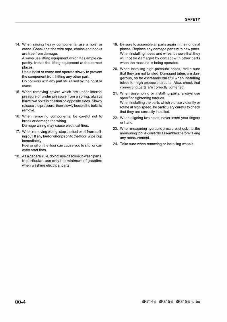
HYDRAULIC CIRCUIT SK714-5 (STANDARD)
STRUCTURE AND FUNCTION HYDRAULIC CIRCUIT SK714-5 (STANDARD)

RIGHT BUCKET CYLINDER
min. lenght 613 mmcod. 37A6C11300
ł 60 x ł30 stroke 357
LIFT CYLINDER
min. lenght 888 mmcod. 37A6C11100
ł 55 x ł35 stroke 620
LIFT CYLINDER
min. lenght 888 mmcod. 37A6C11100
ł 55 x ł35 stroke 620
LEFT BUCKET CYLINDER
min. lenght 613 mmcod. 37A6C11200
ł 60 x ł30 stroke 357
Pb2
Pb1
AUXILIARY KIT
Pa1
Pa2
Pa3
Pb1 Pb2
Pb3
LEVELING FOR
ARM FLOAT
12V
LEVELING FOR
Pa4Pb4
P:M24X1.5T:M24X1.5
Ts:9/16-18 UNF
UNLOADVALVE
Pa3-4;Pb3-4: M14X1.5Pa1-2;Pb1-2: M10X1.25
A; B: M18X1.5
MAIN VALVE
łi=1/4 [9/16-18 JIC]
łi=1/
4 [9
/16-
18 J
IC]
P
T
LIFTARM BUCKET
100
T
P
L.P2L.P1L.P4L.P3L.P3L.P4L.P1 L.P2
A3B3
20.6 MPa
100
FOWRWARD LEFTTURN
BACKWARD
R.H PPC VALVE L.H PPC VALVE(TRAVEL)(WORKING)
UPDOWN DIGING DUMP
A1B1
A2B2
LIFTARM
BUCKET
MESH MESH
RED
RIGHTTURN
a b c d
a
b
c
d
MICRON147
MICRON147
10MICRON
P
T
MICRON147
MESH100
ATTACHMENTPPC VALVE
B4A4
KIT
HI-FLOW
0304
05
11 12
13
14
RAULIC CIRCUIT SK714-5 (HIGH-FLOW)
HYDRAULIC CIRCUIT SK714-5 (HIGH-FLOW) STRUCTURE AND FUNCTION
HYD
10-14 SK714-5 SK815-5 SK815-5 turbo
1234567891011121314151617181920212223
150 MESH
25 micron
(104 micron)
THE GEAR PUMP FOR THE HIGH-FLOW
MUST BE 36.6 CC/REV; 206 BAR.
ARM LOWERARM RISE
HYDRAULIC MOTORS
A; B: 1/2" GASPP; DR; BR: 1/4" GAS
HYDRAULIC SYSTEM FOR B46
STANDARD VERSION
łi=1/4 [9/16-18 JIC]
łi=1/4 [9/16-18 JIC]
łi=1/4 [9/16-18 JIC]
łi=1/4 [9/16-18 JIC]
łi=1/4 [9/16-18 JIC]
łi=1/4 [9/16-18 JIC]
łi=1/4 [9/16-18 JIC]
łi=1/4 [9/16-18 JIC]
łi=1/4 [9/16-18 JIC]
ENGINE4D88E-5KFD
33.6/2800 kw/rpm
E
T
P
A B
F R F R
APP DRB BR
PP DR BR
RED
A B
1 2 43
RKS03470
01
02
02
10
09
06
07
08
10-15SK714-5 SK815-5 SK815-5 turbo
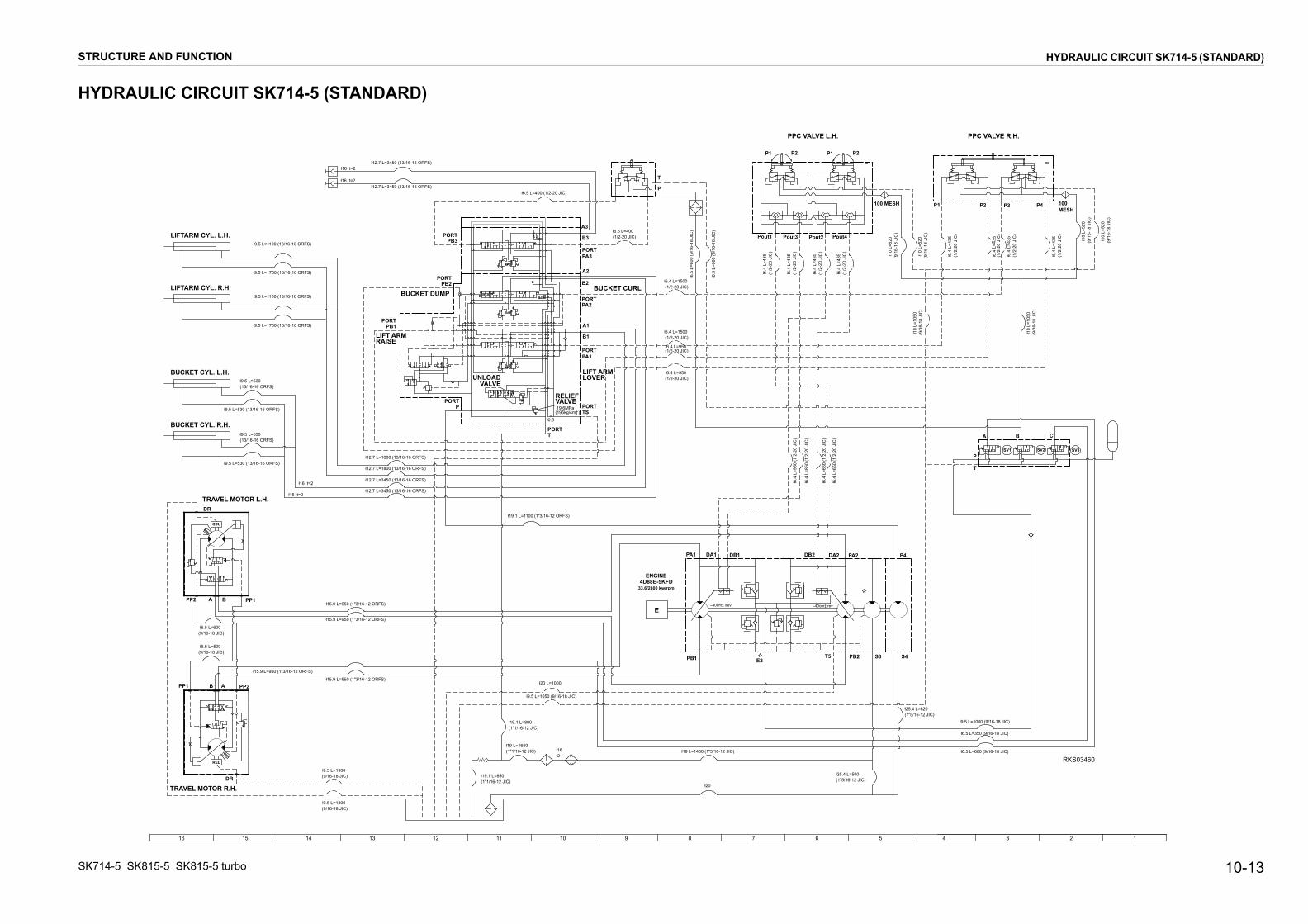
HYDRAULIC CIRCUIT SK714-5 (ROAD HOMOLOGATION)
STRUCTURE AND FUNCTION HYDRAULIC CIRCUIT SK714-5 (ROAD HOMOLOGATION)
12345678910111213141516
TRAVEL MOTOR R.H.
RED
DR
B APP1 PP2
ł6.5 L=500(9/16-18 JIC)
ł9.5 L=1300(9/16-18 JIC)
TRAVEL MOTOR L.H.
RED
DR
BA PP1PP2
ł6.5 L=600(9/16-18 JIC)
ł9.5 L=1300(9/16-18 JIC)
ł19.1 L=850(1"1/16-12 JIC)
ł19 L=1650(1"1/16-12 JIC)
ł19.1 L=800(1"1/16-12 JIC)
ł16t2
ł20 L=1000
ł9.5 L=1050 (9/16-18 JIC)
ł15.9 L=950 (1"3/16-12 ORFS)
ł15.9 L=950 (1"3/16-12 ORFS)
ł15.9 L=950 (1"3/16-12 ORFS)
ł15.9 L=950 (1"3/16-12 ORFS)
BUCKET CYL. R.H.
ł9.5 L=530(13/16-16 ORFS)
ł9.5 L=530(13/16-16 ORFS)
BUCKET CYL. L.H.
ł9.5 L=530(13/16-16 ORFS)
ł9.5 L=530(13/16-16 ORFS)
LIFTARM CYL. R.H.
ł9.5 L=1750(13/16-16 ORFS)
ł9.5 L=1100(13/16-16 ORFS)
LIFTARM CYL. L.H.
ł9.5 L=1750(13/16-16 ORFS)
ł9.5 L=1100(13/16-16 ORFS)
ł12.7 L=1800 (13/16-16 ORFS)
ł12.7 L=1800 (13/16-16 ORFS)
ł12.7 L=3450 (13/16-16 ORFS)
ł12.7 L=3450 (13/16-16 ORFS)
E
ł19.1 L=1100 (1"3/16-12 ORFS)
ł19 L=1450 (1"5/16-12 JIC)
ł20
ł25.4 L=500(1"5/16-12 JIC)
ł25.4 L=620(1"5/16-12 JIC)
ł9.5 L=1000 (9/16-18 JIC)
ł6.5 L=680 (9/16-18 JIC)
ł6.5 L=350 (9/16-18 JIC)
PA1 DA1 DB1 DB2 DA2 PA2 P4
PB1 T5 PB2 S3 S4E2
–40cm‡/rev –40cm‡/rev
SV1 SV2 SV3
A B C
P
T S
B2
A2
B1
A1
RELIEFVALVE
UNLOADVALVE
19.6MPa(195kg/cm†)
ł0.5
B3
PORTPA3
A3
ł6.5 L=400 (1/2-20 JIC)
PORTPB3
PORTPB2
PORTPB1
PORTP
PORTT
BUCKET DUMP BUCKET CURL
LIFT ARMRAISE
PORTTS
PORTPA1
LIFT ARMLOWER
PORTPA2
ł12.7 L=3450 (13/16-16 ORFS)
ł12.7 L=3450 (13/16-16 ORFS)
ł16 t=2
ł16 t=2
ł6.5 L=400(1/2-20 JIC)
T
P
ł6.5
L=6
00 (9
/16-
18 J
IC)
ł6.5
L=6
80 (9
/16-
18 J
IC)
ł6.4 L=1500(1/2-20 JIC)
ł6.4 L=1500(1/2-20 JIC)
ł6.4 L=950(1/2-20 JIC)
ł6.4 L=950(1/2-20 JIC)
P1
PPC VALVE L.H. PPC VALVE R.H.
P2 P2P1
ł6.4
L=4
35(1
/2-2
0 JI
C)
ł6.4
L=4
35(1
/2-2
0 JI
C)
ł6.4
L=4
35(1
/2-2
0 JI
C)
ł6.4
L=4
35(1
/2-2
0 JI
C)
Pout1 Pout3 Pout2 Pout4
ł10
L=52
0(9
/16-
18 J
IC)
ł10
L=52
0(9
/16-
18 J
IC)
100 MESH
ł6.4
L=9
50 (1
/2-2
0 JI
C)
ł6.4
L=8
50 (1
/2-2
0 JI
C)
ł6.4
L=6
50 (1
/2-2
0 JI
C)
ł6.4
L=6
50 (1
/2-2
0 JI
C)
ł10
L=10
50(9
/16-
18 J
IC)
ł6.4
L=4
35(1
/2-2
0 JI
C)
100MESH
ł6.4
L=4
35(1
/2-2
0 JI
C)
ł6.4
L=4
35(1
/2-2
0 JI
C)
ł6.4
L=4
35(1
/2-2
0 JI
C)
ł10
L=52
0(9
/16-
18 J
IC)
ł10
L=52
0(9
/16-
18 J
IC)
ł10
L=10
50(9
/16-
18 J
IC)
ł16 t=2
ł16 t=2
P1 P2 P3 P4
RKA03480
ENGINE4D88E-5KFD
33.6/2800 kw/rpm
10-16 SK714-5 SK815-5 SK815-5 turbo
12345678910111213141516
LIFT ARM RAISE
BUCKET DUMPPORTPA2
PORTPB1
PORTPB2
HYDRAULIC CIRCUIT DIAGRAMTS
B2
A2
P
T
B1
A1
PORTPORT
RELIEFVALVEPORT
UNLOADVALVE
19.1MPa{195kg/cm†}
ł0.5
PORTPA1
LIFT ARMLOWER
PORT
PORTPB3
B3
PA3
A3
RED
RED
P
T
P1
PPC VALVE L.H. PPC VALVE R.H.
P2 P4 P3
P1 P2 P3 P4
SV1
A B C
P
T
E
SV2 SV3
ł12.7 l=3700 (13/16-16 ORFS)ł16 t=2
ł16 t=2 ł12.7 l=3700 (13/16-16 ORFS)
ł6.5 l=400 (1/2-20JIC)
ł6.5 l=400 (1/2-20JIC)
ł9.5 l=1100 (13/16-16 ORFS)
ł9.5 l=1750 (13/16-16 ORFS)
ł9.5 l=1100 (13/16-16 ORFS)
ł9.5 l=1750 (13/16-16 ORFS)
ł9.5 l=530 (13/16-16 ORFS)
ł9.5 l=530 (13/16-16 ORFS)
ł9.5 l=530 (13/16-16 ORFS)
ł9.5 l=530(13/16-16 ORFS)
LIFTARM CYL. L.H.
LIFTARM CYL. R.H.
BUCKET CYL. L.H.
BUCKET CYL. R.H.
Pout1 Pout3 Pout2 Pout4
100MESH
100MESH
ł10 l=520(9/16-18JIC)
ł10 l=520(9/16-18JIC)
ł10 l=520(9/16-18JIC)
ł10 l=520(9/16-18JIC)
ł6.4
l=43
5(1
/2-2
0JIC
)
ł6.4
l=43
5(1
/2-2
0JIC
)
ł6.4
l=43
5(1
/2-2
0JIC
)
ł6.4
l=43
5(1
/2-2
0JIC
)
ł10 l=1050(9/16-18JIC)
ł10 l=1050(9/16-18JIC)
ł6.4
l=43
5(1
/2-2
0JIC
)
ł6.4
l=43
5(1
/2-2
0JIC
)
ł6.4
l=43
5(1
/2-2
0JIC
)
ł6.4
l=43
5(1
/2-2
0JIC
)
ł6.5
l=60
0 (9
/16-
18JI
C)
ł6.5
l=68
0 (9
/16-
18JI
C)
ł6.4 l=1500 (1/2-20JIC)
ł6.4 l=1500 (1/2-20JIC)
ł6.4 l=950 (1/2-20JIC)
ł6.4 l=950 (1/2-20JIC)
ł6.4
l=65
0 (1
/2-2
0JIC
)
ł6.4
l=65
0 (1
/2-2
0JIC
)
ł6.4
l=85
0 (1
/2-2
0JIC
)
ł6.4
l=95
0 (1
/2-2
0JIC
)
ł6.5 l=350 (9/16-18JIC)
ł9.5 l=1000 (9/16-18JIC)
ł6.5 l=680 (9/16-18JIC)
ł25.4 l=620(1"5/16-12 JIC)
ł25.4 l=500(1"5/16-12 JIC)
ł19 l=1450(1"5/16-12 JIC)
ł20
ł20 l=1000
ł9.5 l=1050 (9/16-18JIC)
ł19.1 l=900(1"1/16-12 JIC)
ł19 l=1650(1"1/16-12 JIC)
ł19.1 l=850(1"1/16-12 JIC)
ł16t2
ł19.1 l=1100 (1"3/16-12 ORFS)
ł15.9 l=1000 (1"3/16-12 ORFS)
ł15.9 l=1000 (1"3/16-12 ORFS)
ł15.9 l=1000 (1"3/16-12 ORFS)
ł15.9 l=1000 (1"3/16-12 ORFS)
ł9.5 l=1300 (9/16-18 JIC)
ł9.5 l=1300 (9/16-18 JIC)
ł12.7 l=1950 (13/16-16 ORFS)
ł12.7 l=1950 (13/16-16 ORFS)
ł12.7 l=3700 (13/16-16 ORFS)
ł12.7 l=3700 (13/16-16 ORFS)ł16 t=2
ł16 t=2
PA1 DA1 DB1 DB2 DA2 PA2 P4
ł7.3–40cm‡/rev
PB1 T5 PB2 S3 S4
–40cm‡/rev
TRAVEL MOTOR L.H.
TRAVEL MOTOR R.H.
PP1 B A PP2
ł6.5 l=600(9/16-18 JIC)
ł6.5 l=500(9/16-18 JIC)
PP2A B
PP1
DR
DR
RKS03490
SK815-5ENGINE
4D88E-5KFD33.6/2800 kw/rpm
SK815-5 turboENGINE
S4D84E-5KFD38.6/3000 kw/rpm
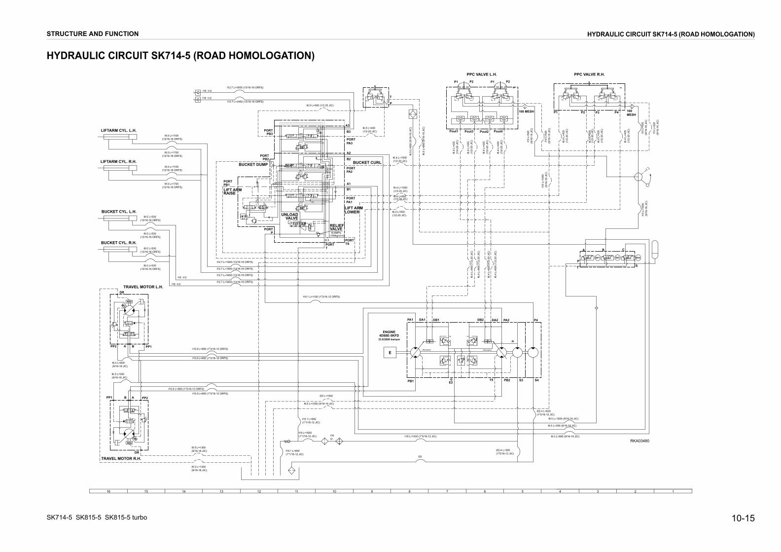
RAULIC CIRCUIT SK815-5 - SK815-5 turbo (STANDARD)
STRUCTURE AND FUNCTION HYDRAULIC CIRCUIT SK815-5 - SK815-5 turbo (STANDARD)
HYD
10-17 SK714-5 SK815-5 SK815-5 turbo
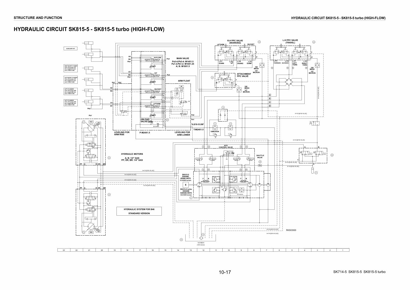
RAULIC CIRCUIT SK815-5 - SK815-5 turbo (HIGH-FLOW)
STRUCTURE AND FUNCTION HYDRAULIC CIRCUIT SK815-5 - SK815-5 turbo (HIGH-FLOW)
1234567891011121314151617181920212223
P
T
LIFTARM BUCKET
100
T
P
L.P2L.P1L.P4L.P3L.P3L.P4L.P1 L.P2
E
A3
B3
T
P
A B
20.6 MPa
F R F R
100
FOWRWARD LEFTTURN
BACKWARD
R.H PPC VALVE L.H PPC VALVE(TRAVEL)(WORKING)
UPDOWN DIGING DUMP
A1
B1
A2
B2
LIFTARM
BUCKET
MESH MESH
APP DRB BR
RED
PP DR BR
RED
A B
RIGHTTURN
a b c d
1 2 43
MICRON147
MICRON147
10MICRON
P
T
MICRON147MESH100
ATTACHMENTPPC VALVE
B4A4 HI-FLOW
1 2 43
KIT
150 MESH
25 micron
RIGHT BUCKET CYLINDER
min. lenght 613 mmcod. 37A6C11300
ł 60 x ł30 stroke 357
LIFT CYLINDER
min. lenght 888 mmcod. 37A6C11100
ł 55 x ł35 stroke 620
(104 micron)
LIFT CYLINDER
min. lenght 888 mmcod. 37A6C11100
ł 55 x ł35 stroke 620
LEFT BUCKET CYLINDER
min. lenght 613 mmcod. 37A6C11200
ł 60 x ł30 stroke 357
Pb2
Pb1
AUXILIARY KIT
Pa1
Pa2
Pa3
Pb1 Pb2
Pb3
LEVELING FORARM LOWER
ARM FLOAT
12V
LEVELING FORARM RISE
Pa4Pb4
P:M24X1.5T:M24X1.5
Ts:9/16-18 UNF
UNLOADVALVE
Pa3-4;Pb3-4: M14X1.5Pa1-2;Pb1-2: M10X1.25
A; B: M18X1.5
HYDRAULIC MOTORS
A; B: 1/2" GASPP; DR; BR: 1/4" GAS
MAIN VALVE
HYDRAULIC SYSTEM FOR B46
STANDARD VERSION
łi=1/4 [9/16-18 JIC]
łi=1/4 [9/16-18 JIC]
łi=1/4 [9/16-18 JIC]
łi=1/
4 [9
/16-
18 J
IC]
łi=1/4 [9/16-18 JIC]
łi=1/4 [9/16-18 JIC]
łi=1/4 [9/16-18 JIC]
łi=1/4 [9/16-18 JIC]
łi=1/4 [9/16-18 JIC]
łi=1/4 [9/16-18 JIC]
RKS03500łi=1/4 [9/16-18 JIC]
CONTROL VALVEACS
VALVESHUTTLE
ł=8
SK815-5ENGINE
4D88E-5KFD33.6/2800 kw/rpm
SK815-5 turboENGINE
S4D84E-5KFD38.6/3000 kw/rpm
a
b
c
d
01
02
02
0304
05
10
11
09
06
07
08
12
13
14
HYD

10-18 SK714-5 SK815-5 SK815-5 turbo
RAULIC CIRCUIT SK815-5 - SK815-5 turbo (ROAD HOMOLOGATION)
STRUCTURE AND FUNCTION HYDRAULIC CIRCUIT SK815-5 - SK815-5 turbo (ROAD HOMOLOGATION)
12345678910111213141516
LIFT ARM RAISE
BUCKET DUMP BUCKET CURLPORTPA2
PORTPB1
PORTPB2
HYDRAULIC CIRCUIT DIAGRAM
TS
B2
A2
P
T
B1
A1
PORT
PORT
RELIEFVALVEPORT
UNLOADVALVE
19.1MPa{195kg/cm†}
ł0.5
PORTPA1
LIFT ARMLOWER
PORT
PORTPB3 B3
PA3
A3
RED
RED
P
T
P1 P2 P4 P3
P1 P2 P3 P4
SV1
A B C
P
T
E
SV2 SV3
ł12.7 l=3700 (13/16-16 ORFS)ł16 t=2
ł16 t=2 ł12.7 l=3700 (13/16-16 ORFS)
ł6.5 l=400 (1/2-20JIC)
ł6.5 l=400 (1/2-20JIC)
ł9.5 l=1750 (13/16-16 ORFS)
ł9.5 l=1100 (13/16-16 ORFS)
ł9.5 l=1750 (13/16-16 ORFS)
ł9.5 l=530 (13/16-16 ORFS)
ł9.5 l=530 (13/16-16 ORFS)
ł9.5 l=530 (13/16-16 ORFS)
ł9.5 l=530(13/16-16 ORFS)
LIFTARM CYL. L.H.
LIFTARM CYL. R.H.
BUCKET CYL. L.H.
BUCKET CYL. R.H.
Pout1 Pout3 Pout2 Pout4
100MESH
100MESH
ł10 l=520(9/16-18JIC)
ł10 l=520(9/16-18JIC)
ł10 l=520(9/16-18JIC)
ł10 l=520(9/16-18JIC)
ł6.4
l=43
5(1
/2-2
0JIC
)
ł6.4
l=43
5(1
/2-2
0JIC
)
ł6.4
l=43
5(1
/2-2
0JIC
)
ł6.4
l=43
5(1
/2-2
0JIC
)
ł10 l=1050(9/16-18JIC)
ł10 l=1050(9/16-18JIC)
ł6.4
l=43
5(1
/2-2
0JIC
)
ł6.4
l=43
5(1
/2-2
0JIC
)
ł6.4
l=43
5(1
/2-2
0JIC
)
ł6.4
l=43
5(1
/2-2
0JIC
)
ł6.5
l=60
0 (9
/16-
18JI
C)
ł6.5
l=68
0 (9
/16-
18JI
C)
ł6.4 l=1500 (1/2-20JIC)
ł6.4 l=1500 (1/2-20JIC)
ł6.4 l=950 (1/2-20JIC)
ł6.4 l=950 (1/2-20JIC)
ł6.4 l=650 (1/2-20JIC)
ł6.4 l=650 (1/2-20JIC)
ł6.4 l=850 (1/2-20JIC)
ł6.4 l=950 (1/2-20JIC)
ł6.5 l=350 (9/16-18JIC)
ł9,5 l=1000 (9/16-18JIC)
ł6.5 l=680 (9/16-18JIC)
ł25.4 l=620(1"5/16-12 JIC)
ł25.4 l=500(1"5/16-12 JIC)
ł19 l=1450(1"5/16-12 JIC)
ł20
ł20 l=1000
ł9.5 l=1050 (9/16-18JIC)
ł19.1 l=900(1"1/16-12 JIC)
ł19 l=1650(1"1/16-12 JIC)
ł19.1 l=850(1"1/16-12 JIC)
ł16t2
ł19.1 l=1100 (1"3/16-12 ORFS)
ł15.9 l=1000 (1"3/16-12 ORFS)
ł15.9 l=1000 (1"3/16-12 ORFS)
ł15.9 l=1000 (1"3/16-12 ORFS)
ł15.9 l=1000 (1"3/16-12 ORFS)
ł9.5 l=1300 (9/16-18 JIC)
ł9.5 l=1300 (9/16-18 JIC)
ł12.7 l=1950 (13/16-16 ORFS)
ł12.7 l=1950 (13/16-16 ORFS)
ł12.7 l=3700 (13/16-16 ORFS)
ł12.7 l=3700 (13/16-16 ORFS)ł16 t=2
ł16 t=2
PA1 DA1 DB1 DB2 DA2 PA2 P4
ł7.3–40cm‡/rev
PB1 T5 PB2 S3 S4
–40cm‡/rev
TRAVEL MOTOR L.H.
TRAVEL MOTOR R.H.
PP1 B A PP2
ł6.5 l=600(9/16-18 JIC)
ł6.5 l=500(9/16-18 JIC)
PP2A B
PP1
DR
DR
RKS03510
S
SK815-5ENGINE
4D88E-5KFD33.6/2800 kw/rpm
SK815-5 turboENGINE
S4D84E-5KFD38.6/3000 kw/rpm
HYD
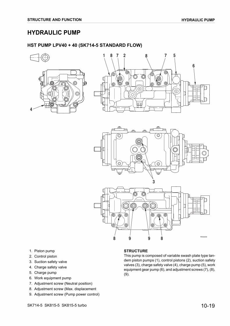
STRUCTURE AND FUNCTION
HYDRAULIC PUMP
HST PUMP LPV40 + 40 (SK714-5 STANDARD FLOW)
RKS00290
4
8 9 9 8
3
1 8 7 2 8 7 5
6
1. Piston pump 2. Control piston 3. Suction safety valve 4. Charge safety valve 5. Charge pump 6. Work equipment pump 7. Adjustment screw (Neutral position) 8. Adjustment screw (Max. displacement 9. Adjustment screw (Pump power control)
STRUCTUREThis pump is composed of variable swash plate type tan-dem piston pumps (1), control pistons (2), suction safety valves (3), charge safety valve (4), charge pump (5), work equipment gear pump (6), and adjustment screws (7), (8), (9).
SK714-5 SK815-5 SK815-5 turbo
HYDRAULIC PUMP
10-19

HST PUMP LPV40 + 40 (SK714-5 HIGH FLOW)
RKS003008 9 9 8
3
1 8 7 2 8 7 5
6
4
1. Piston pump 2. Control piston 3. Suction safety valve 4. Charge safety valve 5. Charge pump 6. Work equipment pump 7. Adjustment screw (Neutral position) 8. Adjustment screw (Max. displacement 9. Adjustment screw (Pump power control)
STRUCTUREThis pump is composed of variable swash plate type tan-dem piston pumps (1), control pistons (2), suction safety valves (3), charge safety valve (4), charge pump (5), work equipment gear pump (6), and adjustment screws (7), (8), (9).
10-20
HYDRAULIC PUMP
STRUCTURE AND FUNCTIONSK714-5 SK815-5 SK815-5 turbo

HST PUMP LPV40 + 40 (SK815-5 – SK815-5 turbo STANDARD FLOW)
RKS00310
4
10
8 9 9 8
311
1 8 7 2 8 7 5
6
11
1. Piston pump 2. Control piston 3. Suction safety valve 4. Charge safety valve 5. Charge pump 6. Work equipment pump 7. Adjustment screw (Neutral position) 8. Adjustment screw (Max. displacement
9. Adjustment screw (Pump power control)10. AS valve11. Shuttle valve
STRUCTUREThis pump is composed of variable swash plate type tan-dem piston pumps (1), control pistons (2), suction safety valves (3), charge safety valves (4), charge pump (5), work equipment gear pump (6), and adjustment screws (7), (8), (9), AS valve (10), and shuttle valves (11).
SK714-5 SK815-5 SK815-5 turbo
HYDRAULIC PUMP
STRUCTURE AND FUNCTION10-21

HST PUMP LPV40 + 40 (SK815-5 – SK815-5 turbo HIGH FLOW)
RKS00320
4
10
11 113
1 8 7 2 8 7 5
6
8 9 9 8 1. Piston pump 2. Control piston 3. Suction safety valve 4. Charge safety valve 5. Charge pump 6. Work equipment pump 7. Adjustment screw (Neutral position) 8. Adjustment screw (Max. displacement) 9. Adjustment screw (Pump power control)10. AS valve11. Shuttle valve
STRUCTUREThis pump is composed of variable swash plate type tan-dem piston pumps (1), control pistons (2), suction safety valves (3), charge safety valve (4), charge pump (5), work equipment gear pumps (6), and adjustment screws (7), (8), (9), AS valve (10), and shuttle valves (11).
10-22
HYDRAULIC PUMP
STRUCTURE AND FUNCTIONSK714-5 SK815-5 SK815-5 turbo

SK815-5 – SK815-5 turbo (STANDARD FLOW AND HIGH FLOW) SK714-5FUNCTION
• The rotation and torque transmitted to the pump shaft is converted into hydraulic energy, and pressurized oil is di-scharged according to the load.• It is possible to change the discharge amount by changing the swash plate angle (plus, zero and minus)
RKS00351
14
1
3
4 2 5 6
15
11
7A 12 10 138 9 15
(Standard version)
(High-flow version )
1. Shaft 2. Case 3. Cradle bearing 4. Rocker cam 5. Control piston
6. Slider 7. Shoe 8. Piston 9. Cylinder block10. Valve plate
11. Main bearing12. Spline13. Sub bearing14. Charge pump15. Work equipment pump
STRUCTURE• Cylinder block (9) is supported to shaft (1) by a spline
(12), and shaft (1) is supported by the front and rear bearings (11), (13). The tip of piston (8) is a concave ball, and shoe (7) is caulked to it to form one unit. Piston (8) and shoe (7) form a spherical bearing.
• Rocker cam (4) has flat surface A, and shoe (7) is always pressed against this surface while sliding in a circular movement. There is a cradle bearing (3) between cradle and roc-ker cam (4) which is secured to the case. Rocker cam (4) sways on cradle bearing.
• Piston (8) carries out relative movement in the axial direction inside each cylinder chamber of cylinder block (9).
• The cylinder block seals the pressurized oil to valve plate (10) and carries out relative rotation. This sur-face is designed so that the oil pressure balance is maintained at a suitable level. The oil inside each cylinder chamber of cylinder block (9) is sucked in and discharged through valve palte (10).
SK714-5 SK815-5 SK815-5 turbo
HYDRAULIC PUMP
STRUCTURE AND FUNCTION10-23
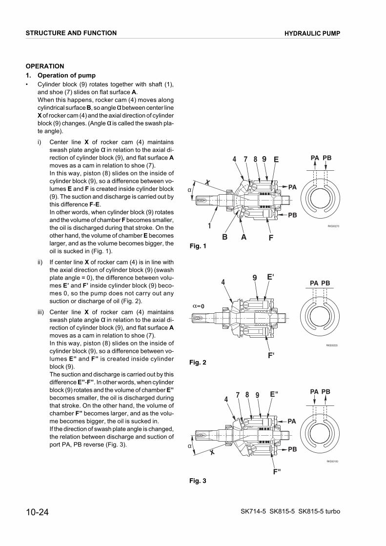
OPERATION1. Operation of pump
RKS002701
4 7 8 9 E
PA
PB
PA PB
αX
A FBFig. 1
RKS00220
4 9 E'PA PB
F'
0
Fig. 2
RKS00100
4 7 8 9
PA
PB
PA PB
αX
F"
E"
Fig. 3
• Cylinder block (9) rotates together with shaft (1), and shoe (7) slides on flat surface A. When this happens, rocker cam (4) moves along cylindrical surface B, so angle α between center line X of rocker cam (4) and the axial direction of cylinder block (9) changes. (Angle α is called the swash pla-te angle).
i) Center line X of rocker cam (4) maintains swash plate angle α in relation to the axial di-rection of cylinder block (9), and flat surface Amoves as a cam in relation to shoe (7). In this way, piston (8) slides on the inside of cylinder block (9), so a difference between vo-lumes E and F is created inside cylinder block (9). The suction and discharge is carried out by this difference F-E. In other words, when cylinder block (9) rotates and the volume of chamber F becomes smaller, the oil is discharged during that stroke. On the other hand, the volume of chamber E becomes larger, and as the volume becomes bigger, the oil is sucked in (Fig. 1).
ii) If center line X of rocker cam (4) is in line with the axial direction of cylinder block (9) (swash plate angle = 0), the difference between volu-mes E’ and F’ inside cylinder block (9) beco-mes 0, so the pump does not carry out any suction or discharge of oil (Fig. 2).
iii) Center line X of rocker cam (4) maintains swash plate angle α in relation to the axial di-rection of cylinder block (9), and flat surface Amoves as a cam in relation to shoe (7). In this way, piston (8) slides on the inside of cylinder block (9), so a difference between vo-lumes E” and F” is created inside cylinder block (9). The suction and discharge is carried out by this difference E”-F”. In other words, when cylinder block (9) rotates and the volume of chamber E”becomes smaller, the oil is discharged during that stroke. On the other hand, the volume of chamber F” becomes larger, and as the volu-me becomes bigger, the oil is sucked in. If the direction of swash plate angle is changed, the relation between discharge and suction of port PA, PB reverse (Fig. 3).
10-24
HYDRAULIC PUMP
STRUCTURE AND FUNCTIONSK714-5 SK815-5 SK815-5 turbo

2. Control of discharge amount
• If swash plate angle α becomes larger, the difference between volumes E and F becomes larger and dischargeamount Q increases.• Swash plate angle α is changed by control piston (5).• Control piston (5) moves in a reciprocal movement ( ) according to the signal pressure from pilot line (PPC and
AS valves). This straight line movement is transmitted through slider (6) to rocker cam (4), which is supported by the cylindrical surface to cradle, slides in a rotating movement in direction ( ).
• On this pump, maximum swash plate angle is ±15.8°..
• Screw A restricts to the maximum stroke of control piston (i.e. maximum displacement of each pump). When screw A is tightened, maximum displacement decreases, and when screw A is loosened, maximum displacement in-crease. This screw should be adjusted when the machine doesn’t travel straight or machine maximum speed is little bit wrong.
• Screw B is the fine adjuster of neutral position of control piston (5). That adjust prevent machine from creep.
RKS00360
3
4RKS00280
3
6
4
5
RKS00260
A
B
A A5
6
4
5
6
4
BSK714-5 SK815-5 - SK815-5 turbo
SK714-5 SK815-5 SK815-5 turbo
HYDRAULIC PUMP
STRUCTURE AND FUNCTION10-25
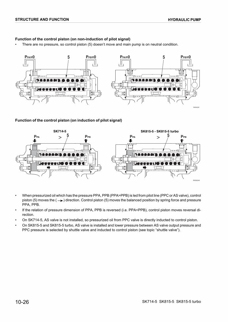
Function of the control piston (on non-induction of pilot signal)• There are no pressure, so control piston (5) doesn’t move and main pump is on neutral condition.
Function of the control piston (on induction of pilot signal)
• When pressurized oil which has the pressure PPA, PPB (PPA>PPB) is led from pilot line (PPC or AS valve), control piston (5) moves the ( ) direction. Control piston (5) moves the balanced position by spring force and pressure PPA, PPB.
• If the relation of pressure dimension of PPA, PPB is reversed (i.e. PPA<PPB), control piston moves reversal di-rection.
• On SK714-5, AS valve is not installed, so pressurized oil from PPC valve is directly inducted to control piston.• On SK815-5 and SK815-5 turbo, AS valve is installed and lower pressure between AS valve output pressure and
PPC pressure is selected by shuttle valve and inducted to control piston (see topic “shuttle valve”).
RKS00230
PPA=0 PPB=0 PPA=0 PPB=05 5
RKS00240
PPA PPBPPA PPB >> 5 5SK714-5 SK815-5 - SK815-5 turbo
10-26
HYDRAULIC PUMP
STRUCTURE AND FUNCTIONSK714-5 SK815-5 SK815-5 turbo

SUCTION SAFETY VALVE
1. Charge pump 2. Charge safety valve 3. Suction safety valve
3A. Valve3B. Rod3C. Sleeve3D. Spring3E. Spring3F. Plug
4. Piston pump 5. Travel motor
FUNCTIONThere are two suction safety valves installed to each HST pump, and they have the following functions:
1) High pressure safety valve The valve restricts the maximum pressure inside the HST circuit in order to protect the HST circuit.
2) Suction safety valve The valve ensures the flow of the charge oil to the closed HST circuit and prevents the charge oil from flowing into the pump high pressure side (delivery side).
RKS00110
4
3
13
5
2
RKS00090
3A 3B 3C 3D 3F3E
SK714-5 SK815-5 SK815-5 turbo
HYDRAULIC PUMP
STRUCTURE AND FUNCTION10-27

Actuation when acting as high pressure relief valve (Valve at piston pump delivery side)
Port A is connected to the piston pump circuit and port B is connected to the charge circuit. The pressurized oil fills
port C through drill hole a of piston (3A). The pressurized oil at high pressure port A fills port D through groove bbetween body and valve. Poppet (3A) is in tight contact with valve seat (3C).• If abnormal pressure is generated in the circuit and the oil pressure at ports A and D reaches to the pressure set by spring (3D), poppet (3A) is pushed to direction, and oil at port A is relieved to port B to reduce the oil pressure at port A.
RKS00050
3A 3B 3C 3D 3EB
a A b C D
RKS00060
a A b D
B 3A
3D
10-28
HYDRAULIC PUMP
STRUCTURE AND FUNCTIONSK714-5 SK815-5 SK815-5 turbo

Operation when acting as suction safety valve 1) When HST pump delivery is 0.
The HST circuit is closed, and the charge oil does not flow into the HST circuit. Therefore the charge pressurized oil from the charge pump (1) all passes the charge safety valve (2) and is drained to the pump case.
RKS00121
PB PA
Travel motor
Travel pump
2
3
13
SK714-5 SK815-5 SK815-5 turbo
HYDRAULIC PUMP
STRUCTURE AND FUNCTION10-29

2. When HST pump discharges from port PA 1) Valve at the piston pump delivery side.
When the pressure oil is discharged from port PA of the HST pump (4), port PA becomes the high pressure side. This pressure oil at port PA flow into port D through the groove b. When this happen, sleeve (3C) is pushed to direction, because of the difference in area (A1>A2). Therefore the pressure oil from charge pump is prevented from flowing into HST pump.
2) Valve at piston pump suction side Port PB is at low pressure because port PB is suction side. And sleeve (3C) is pushed to direction to open body seat portion because of the difference in area (A1>A2). In this way, the charge pressure oil at port B flows into port PB through this clearance to charge to the HST circuit..
RKS00130
PAPB
PAPB
4
1
RKS00070
3C b D
A1A2
PA
RKS00080
3C
A1 A2
PB
B
10-30
HYDRAULIC PUMP
STRUCTURE AND FUNCTIONSK714-5 SK815-5 SK815-5 turbo
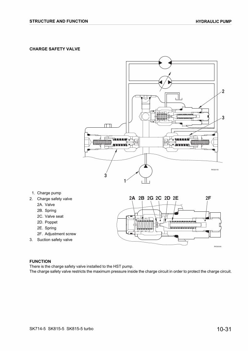
CHARGE SAFETY VALVE
1. Charge pump2. Charge safety valve
2A. Valve2B. Spring2C. Valve seat2D. Poppet2E. Spring2F. Adjustment screw
3. Suction safety valve
FUNCTIONThere is the charge safety valve installed to the HST pump. The charge safety valve restricts the maximum pressure inside the charge circuit in order to protect the charge circuit.
RKS00140
2
3
13
RKS00040
2A 2B 2G 2C 2D 2E 2F
SK714-5 SK815-5 SK815-5 turbo
HYDRAULIC PUMP
STRUCTURE AND FUNCTION10-31

FUNCTION• Port A is connected to the charge circuit.
Port B is connected to the tank drain circuit. The pressurized oil fills port C through orifice a in valve (2A). Poppet (2D) is in tight contact with valve seat (2C)
• If abnormal pressure is generated in the circuit or the shuttle valve of HST motor is at neutral and the oil pressure at ports A and C reaches the pressure set by spring (2E), poppet (2D) is pushed to direction, and oil at C is relieved to port B and pressure of the oil at C reduce.
• When the pressure of the oil at port C goes down, a differential pressure is occured between ports A and C because of orifice a in valve (2A). Valve (2A) is pushed to direction by oil pressure at port A, and oil at port A is relieved to port B. In this way, the pressure in the charge circuit is prevented from going any higher.
RKS00010
12A 2C 2D
a
C
A
2E
B
RKS00020
A
2D 2E2A
B
C
RKS00030
B
A
2A
a
C
10-32
HYDRAULIC PUMP
STRUCTURE AND FUNCTIONSK714-5 SK815-5 SK815-5 turbo

CHARGE PUMP
RKS00150
1
2
6
7
4
5
3
1. Slide plate 2. Coupling 3. Shaft 4. Outer ring 5. Case 6. Inner roter 7. Outer roter
FUNCTION• HST charge pump is built-in the HST pump and driven
with HST pump at the same time.• Discharged oil is delivered to AS valve and charge sa-
fety valve. (AS valve is only installed SK815-5 and SK815-5 turbo).
• Charge pump sucks oil from hydraulic tank.
SPECIFICATIONS• Type: trochoid pump• Theoletical delivery: 25 cm³/rev
SK714-5 SK815-5 SK815-5 turbo
HYDRAULIC PUMP
STRUCTURE AND FUNCTION10-33

FUNCTION
• Charge pump is connected to HST pump shaft by coupling (2), so inner roter (6) and outer roter (7) rotate.• When inner roter (6) and outer roter (7) rotate, capacity of A increase and oil is sucked, and capacity of B decrease
and oil discharge.
RKS00161
Suction port
Discharge port
Discharge side
Suction side
7 6 B
A
A
A
2
10-34
HYDRAULIC PUMP
STRUCTURE AND FUNCTIONSK714-5 SK815-5 SK815-5 turbo

ANTI ENGINE-STALL CONTROL VALVE (AS VALVE)
RKS00170
4
3
2
1A 1B 1C 1F 1D 1E
1G 1H1L
E
5
1. AS valve1A. Nut1B. Screw1C. Spring1D. Spring1E. Spring1F. Valve1G. Valve1H. Nut1L. Screw
2. Charge pump 3. Orifice 4. Charge safety valve 5. Engine
FUNCTION• The AS valve is attached on the main piston pump. It
reduces pressure for pump swash plate control from charge circuit.
• The AS valve outputs pressure correspond with en-gine revolution.
SK714-5 SK815-5 SK815-5 turbo
HYDRAULIC PUMP
STRUCTURE AND FUNCTION10-35

OPERATION
• The oil from the charge pump (2) that rotates with the engine flows through a orifice (3) that is installed in the main piston pump. And the oil always flows to pump charge circuit.
• Charge pump (2) is fixed capacity pump, so that discharge flow is proportionate to engine rotation speed. With the oil from the charge pump (2) passed through the orifice, differential pressure is generated at port A and port B. This differential pressure actuates the differential pressure sensing valve (1G) and makes hydraulic force F.
• By the hydraulic force F, the differential pressure sensing valve (1G) is moved direction. That makes a change of spring (1D) load. In port C, the AS valve output pressure that is balanced with spring (1C) and (1D) load is generated by reducing from charge pressure of port G. So the AS valve outputs pressure correspond with charge flow that is changed by engine (5) revolution.
RKS00180
3
2
1C 1D 1G
B
D E
CG
F
E
5A
10-36
HYDRAULIC PUMP
STRUCTURE AND FUNCTIONSK714-5 SK815-5 SK815-5 turbo

SHUTTLE VALVE
RKS002001 23
1. Valve 2. Plug 3. Cover
FUNCTION• The shuttle valves are installed in covers of pump
swash plate control pistons. They select lower pres-sure either travel PPC pressure or AS valve pressure, and output to pump swash plate control pressure.
OPERATION• Port C is connected to port A (Travel PPC pressure inlet port). And hydraulic force F1 by travel PPC pressure ac-
tuates the valve (1).• And port D is connected to port B (AS pressure inlet port). Hydraulic force F2 by AS valve pressure actuates the val-
ve (1).• By the hydraulic force F1 and F2, the shuttle valve selects lower pressure either PPC pressure or AS valve pressure.
It outputs lower pressure of them from port E to control pump swash plate.
RKS00210
1
D B A C
E
F2 F1
SK714-5 SK815-5 SK815-5 turbo
HYDRAULIC PUMP
STRUCTURE AND FUNCTION10-37

CONTROL VALVE (3-SPOOL)SK714-5 – SK815-5 – SK815-5 turbo STANDARD
RKS00250
A
A
G G
F F
E E
C C
D
DB
B
PB2
PB1
PB3
B3 A3
A2
A1
P1
B2
B1
T
PA2
PA1
PA3
TS
P1: from gear pumpT: to tankTs: to tankA1: to lift arm cylinder (head side)A2: to bucket cylinder (head side)
A3: to attachment portB1: to lift arm cylinder (bottom side)B2: to bucket cylinder (bottom side)B3: to attachment port
10-38
CONTROL VALVE
STRUCTURE AND FUNCTIONSK714-5 SK815-5 SK815-5 turbo
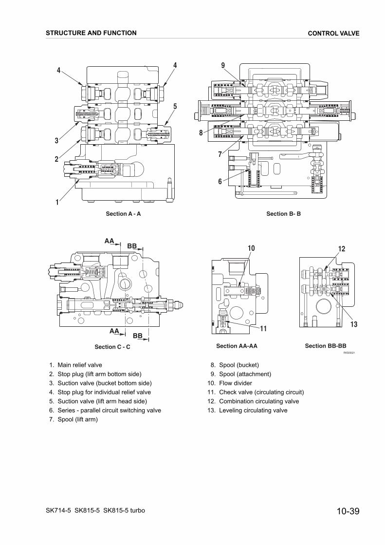
Section A - A
RKS00521
Section B- B
Section BB-BBSection AA-AASection C - C
1
3
4
2
5
4
8
7
6
9
1210
1311
AABB
AABB
1. Main relief valve 2. Stop plug (lift arm bottom side) 3. Suction valve (bucket bottom side) 4. Stop plug for individual relief valve 5. Suction valve (lift arm head side) 6. Series - parallel circuit switching valve 7. Spool (lift arm)
8. Spool (bucket) 9. Spool (attachment)10. Flow divider11. Check valve (circulating circuit)12. Combination circulating valve13. Leveling circulating valve
SK714-5 SK815-5 SK815-5 turbo
CONTROL VALVE
STRUCTURE AND FUNCTION10-39

RKS00671
Section D - D
Section E - E
Section G - GSection F - F
1112
313 6
9 8 9
72
5
14
4 5
15 15
2
6
7
1
3
4
10
1. Unload valve 2. Pressure compensation valve F (lift arm) 3. Pressure compensation valve F (bucket) 4. Pressure compensation valve F (attachment) 5. Pressure compensation valve R (attachment) 6. Pressure compensation valve R (bucket) 7. Pressure compensation valve R (lift arm) 8. Spool (lift arm) 9. Suction valve
10. Shuttle valve11. Spool (bucket)12. Suction valve13. Shuttle valve14. Spool (attachment)15. Stop plug for individual relief valve
★ F: Flow control valveR: Pressure reducing valve
10-40
CONTROL VALVE
STRUCTURE AND FUNCTIONSK714-5 SK815-5 SK815-5 turbo

CONTROL VALVE (4-SPOOL)
SK815-5 – SK815-5 turbo SUPER HIGH-FLOW
RKS00370
P2
A
A
PB2
Pi
PB1
PB3H H
G G
F F
E E
J J
D D
B4 A4A3
A2
P1
B3
B2
T
B1 A1
C
CB
B
PA2
PA1
PA3
TS
P1. from gear pumpP2: from gear pumpT: to tankTs: to tankPi2: From solenoid valve group ST2 (S port)A1: to lift arm cylinder (head side)A2: to bucket cylinder (head side)
A3: to attachment portA4: to High - Flow portB1: to lift arm cylinder (bottom side)B2: to bucket cylinder (bottom side)B3: to attachment portB4: to High-Flow attachment port
SK714-5 SK815-5 SK815-5 turbo
CONTROL VALVE
STRUCTURE AND FUNCTION10-41
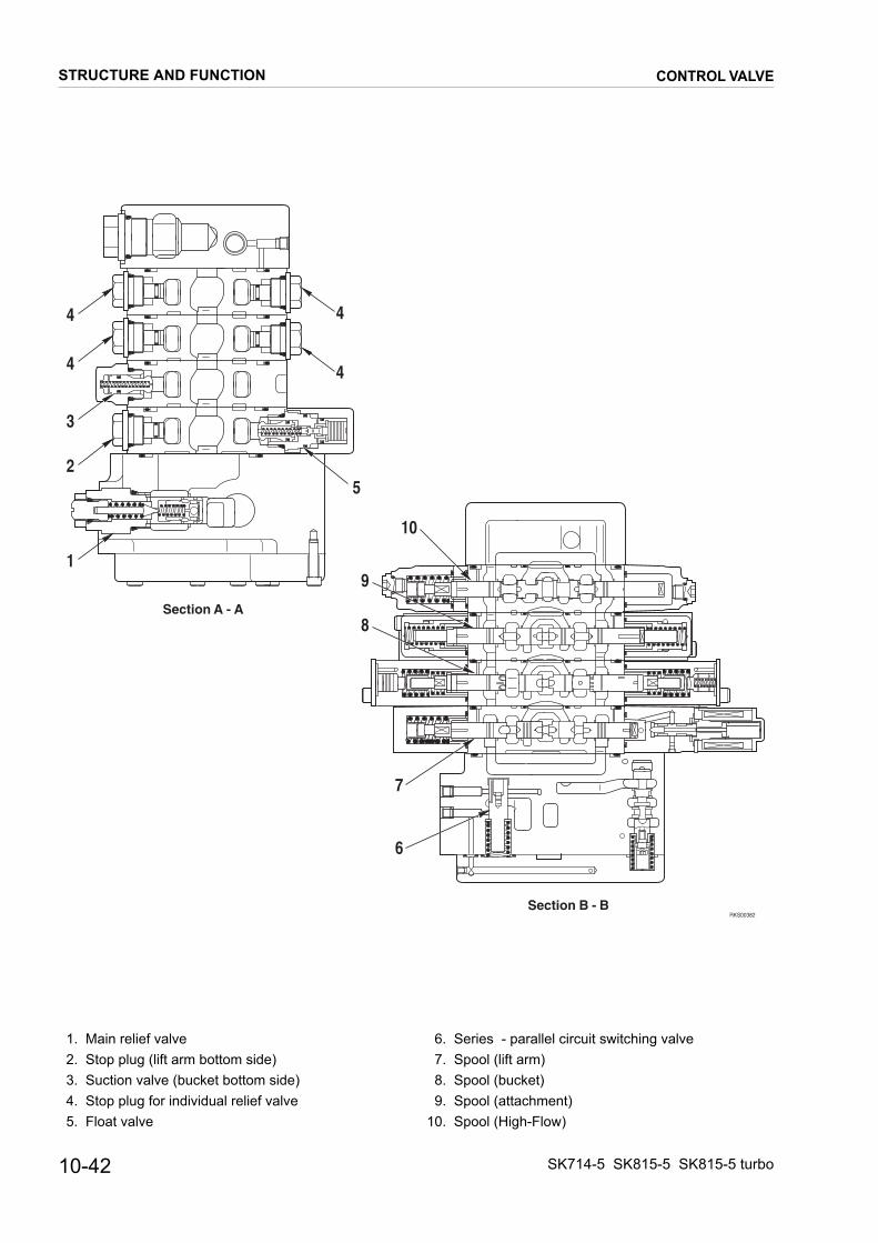
RKS00382
Section A - A
Section B - B
4
4
3
2
1
4
4
10
5
9
8
7
6
1. Main relief valve 2. Stop plug (lift arm bottom side) 3. Suction valve (bucket bottom side) 4. Stop plug for individual relief valve 5. Float valve
6. Series - parallel circuit switching valve 7. Spool (lift arm) 8. Spool (bucket) 9. Spool (attachment)10. Spool (High-Flow)
10-42
CONTROL VALVE
STRUCTURE AND FUNCTIONSK714-5 SK815-5 SK815-5 turbo

RKS00701
Section C - C
Section D - D
Section BB-BB
Section AA-AA
67
8
9
10
5
4
3
2
1
11
13 12
14
AABB
AABB
1. Unload valve 2. Pressure compensation valve F (lift arm) 3. Pressure compensation valve F (bucket) 4. Pressure compensation valve F (attachment) 5. Pressure compensation valve F (High Flow) 6. Check valve (for High - Flow joining circuit) 7. Pressure compensation valve R (High Flow) 8. Pressure compensation vavle R (attachment) 9. Pressure compensation valve R (bucket)
10. Pressure compensation valve R (lift arm)11. Combination circulating valve12. Leveling circulating valve13. Flow-divider14. Check valve (circulating circuit)
★ F: Flow control valveR: Pressure reducing valve
SK714-5 SK815-5 SK815-5 turbo
CONTROL VALVE
STRUCTURE AND FUNCTION10-43

RKS00681
Section G - G
15
16
17
16
14
Section J - J
22
21
Section F - F
1011
12913
Section E - E78
3
2 4
1
5
Section H - H
19
16
5
16
20185
5
6
1. Pressure compensation valve F (lift arm) 2. Spool (lift arm) 3. Stop plug 4. Float valve 5. On - off solenoid 6. Spool (float) 7. Pressure compensation valve F (lift arm) 8. Shuttle valve 9. Pressure compensation valve R (bucket)10. Spool (bucket)11. Suction valve12. Pressure compensation valve R (bucket)
13. Shuttle valve14. Pressure compensation valve F (attachment)15. Spool (attachment)16. Stop plug for individual relief valve17. Pressure compensation valve R (attachment)18. Pressure compensation valve F (High Flow)19. Spool (High - Flow)20. Pressure compensation valve R (High Flow)21. Check valve (High - Flow joining circuit)22. Spool (High Flow joining)
★ F: Flow control valveR: Pressure reducing valve
10-44
CONTROL VALVE
STRUCTURE AND FUNCTIONSK714-5 SK815-5 SK815-5 turbo

CLSS
1. OUTLINE
Features• CLSS stands for Closed center Load Sensing System, and has the followings characteristics.1 - Controlability, not influenced by load.2 - Controllable digging force at fine control range.3 - Easy simultaneous operation by spool opening proportional flow dividing function.
2. PRESSURE COMPENSATION CONTROLA valve (pressure compensation valve) is installed to the inlet port side of the control valve to balance the load.When there is compound operation of the actuators, this valve acts to make pressure difference ∆P constant for the up-stream flow (inlet port) and downstream flow (outlet port) of the notch of each spool. In this way, the flow of oil from the pump is divided in proportion to area of opening S1 and S2 of each valve.
W
S1
W
S1
Pump
Pressurecompensationvalve
Load
Actuator
Pressurecompensationvalve
Load
Actuator
RKS00691
∆ P ∆ P
SK714-5 SK815-5 SK815-5 turbo
CLSS
STRUCTURE AND FUNCTION10-45

3. OPERATION FOR EACH FUNCTION AND VALVE
Features
• The small capacity gear pump keeps high speed movement because lift arm and the bucket circuit are connectedin a series circuit.• The control valve has built in self leveling function.• If loading pressure of bucket becomes beyond a certain value, the lift arm and the bucket circuits automatically chan-
ge to parallel circuit to keep strong digging force.• The lift arm, attachment and High-flow section are connected in a parallel circuit and it has pressure compensa-
tioning function each section.• During individual operations, attachment High-flow keep individual demand flow rate.
However during compound operations, they are divided in the proportion of 1 to 9 and keep High-flow section flow rate. (SK815-5 and SK815-5 turbo has only Super-flow specification.)
Hydraulic circuit diagram and names of valves
RKS00751
Raise arm
Dump bucket
A4
B4
P1
P2
A3
B3
A2
B2
Pa3Pa3
A1
B1
Pa2
Pa1
6
13
12
3
4
812
10
11
9
7
Pa1
Optional equipmentHigh-flow
Ls
Port
Bucket cylinder
5
Pa2 Curl bucket
Raise cylinder
Lower arm
11
Optional equipment
1. Unload valve 2. Main relief valve 3. Pressure compensation valve (lift arm) 4. Pressure compensation valve (bucket) 5. Pressure compensation valve (attachment) 6. Pressure compensation valve (High - Flow) 7. Float valve
8. Leveling circulating valve 9. Combination circulating valve10. Flow divider11. Shuttle valve12. Check valve (circulating circuit)13. High - Flow joining spool
10-46
CLSS
STRUCTURE AND FUNCTIONSK714-5 SK815-5 SK815-5 turbo

3.1 SERIES CIRCUITFunction
• Return flow rate from the lift arm is recirculated to the bucket.OperationWhen the lift arm raise and the bucket dump are operated at the same time.• The lift arm spool (1) strokes fully and the bucket spool (2) stokes by half.• When this happens, notch (a ) doesn’t open, so all flow rate from pump supplies to the lift arm raise.• The lift arm and the bucket PPC pressure are sent by passage E and F.
Then the leveling circulating valve (3) and the combination circulating valve (4) stroke fully.• Return flow rate from the lift arm cylinder passes through passage A.
Then it is divided to passage B and C, by the leveling circulating valve (4) and the combination circulating valve (3).• When this happens, the flow divider (5) is operated as P1=P2, so flow rate (Q1, Q2) is divided to passage B and C
in proportion to the area of opening of notch (b) and (c) as below expression. Q1:Q2= (notch (b) + notch (d) ): notch (C) Q1= flow rate flows to B, Q2= flow rate flows to C
• Q1 passes through the check valve (6) and then supplies to the bucket cylinder.
RKS00720
P2
P1
Q1
Q2
56
2
1
3
4d
F
b
a
D
c
CB
E
A
SK714-5 SK815-5 SK815-5 turbo
CLSS
STRUCTURE AND FUNCTION10-47
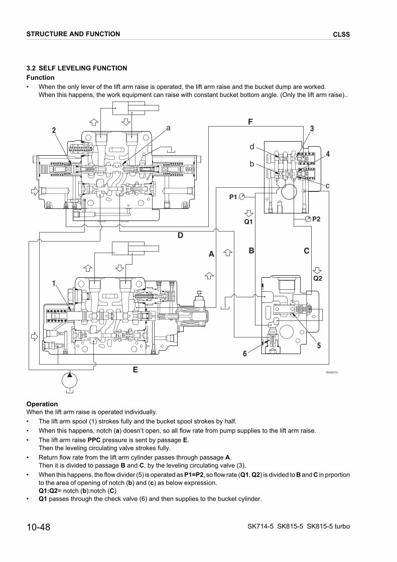
3.2 SELF LEVELING FUNCTIONFunction
• When the only lever of the lift arm raise is operated, the lift arm raise and the bucket dump are worked.When this happens, the work equipment can raise with constant bucket bottom angle. (Only the lift arm raise)..
OperationWhen the lift arm raise is operated individually.• The lift arm spool (1) strokes fully and the bucket spool strokes by half.• When this happens, notch (a) doesn’t open, so all flow rate from pump supplies to the lift arm raise.• The lift arm raise PPC pressure is sent by passage E.
Then the leveling circulating valve strokes fully.• Return flow rate from the lift arm cylinder passes through passage A.
Then it is divided to passage B and C, by the leveling circulating valve (3).• When this happens, the flow divider (5) is operated as P1=P2, so flow rate (Q1, Q2) is divided to B and C in prportion
to the area of opening of notch (b) and (c) as below expression. Q1:Q2= notch (b):notch (C)
• Q1 passes through the check valve (6) and then supplies to the bucket cylinder.
RKS00720
P2
P1
Q1
Q2
56
2
1
3
4d
F
b
a
D
c
CB
E
A
10-48
CLSS
STRUCTURE AND FUNCTIONSK714-5 SK815-5 SK815-5 turbo
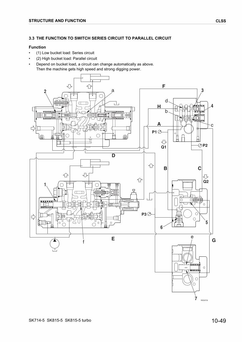
3.3 THE FUNCTION TO SWITCH SERIES CIRCUIT TO PARALLEL CIRCUIT
Function
• (1) Low bucket load: Series circuit• (2) High bucket load: Parallel circuit• Depend on bucket load, a circuit can change automatically as above.Then the machine gets high speed and strong digging power.
RKS00730
56
2
1
3
4
P2
P1
Q1
Q2
P3
7
d
F
A
D
B C
G
b
c
a
fe
H
E
SK714-5 SK815-5 SK815-5 turbo
CLSS
STRUCTURE AND FUNCTION10-49

Operation
When the lift arm raise and the bucket digging are operated at the same time.• The lift arm spool (1) and the bucket spool (2) stroke fully.• When this happens, the bucket digging PPC pressure is sent by passage H.Then the combination circulating valve (3) strokes fully to the right and also the lift arm raise PPC pressure is sent by passage E. Then the leveling circulating valve (4) strokes fully to the left.
• Return flow rate from the lift arm cylinder passes through passage A. Then it is divided to passage B and C, by the leveling circulating valve (4) and the combination circulating valve (3).
• When this happens, the flow divider (5) is operated as P1=P2, so flow rate (Q1, Q2) is divided to passage B and Cin proportion to the area of opening as below expression. Q1:Q2= (notch (b) + notch (d)): notch (C) Q1= flow rate flows to B Q2=flow rate flows to C
• If the bucket load becomes beyond a certain valve by influences of digging, the series-parallel switching valve (7) strokes to the right. Then it passes thorough passage G by opening notch (e). And then the spring chamber of flow divider (5) is connected to tank.
• As a result, flow divider strokes fully to the right, and P2=T Return flow rate from the lift arm is connected with tank totally, and Q1=0L/min.
• When this happens, notch (f) of the lift arm spool and notch (a) of the bucket spool open, so the lift arm and the bucket become parallel circuit (CLSS). And flow rate of the lift arm raise (Q3) and teh bucket digging flow rate are divided as below expression. Q3:Q4= notch (f): notch (a)
10-50
CLSS
STRUCTURE AND FUNCTIONSK714-5 SK815-5 SK815-5 turbo
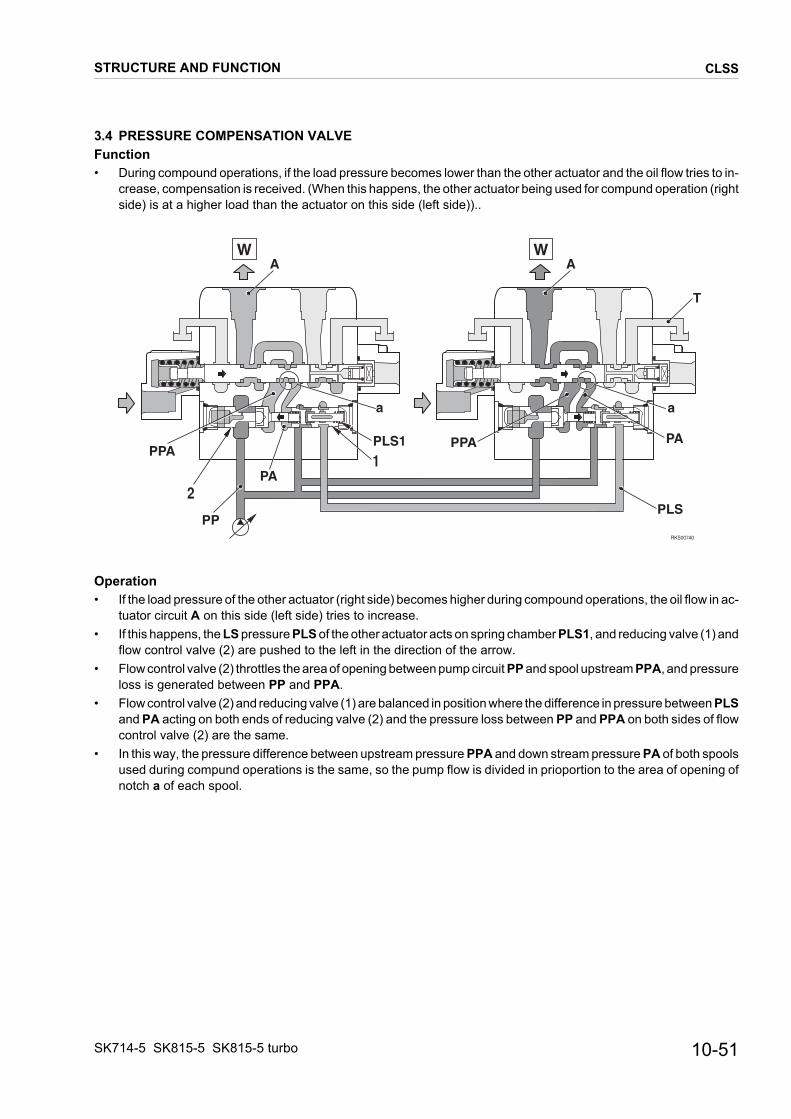
3.4 PRESSURE COMPENSATION VALVEFunction
• During compound operations, if the load pressure becomes lower than the other actuator and the oil flow tries to in-crease, compensation is received. (When this happens, the other actuator being used for compund operation (right side) is at a higher load than the actuator on this side (left side))..
Operation• If the load pressure of the other actuator (right side) becomes higher during compound operations, the oil flow in ac-
tuator circuit A on this side (left side) tries to increase.• If this happens, the LS pressure PLS of the other actuator acts on spring chamber PLS1, and reducing valve (1) and
flow control valve (2) are pushed to the left in the direction of the arrow.• Flow control valve (2) throttles the area of opening between pump circuit PP and spool upstream PPA, and pressure
loss is generated between PP and PPA.• Flow control valve (2) and reducing valve (1) are balanced in position where the difference in pressure between PLS
and PA acting on both ends of reducing valve (2) and the pressure loss between PP and PPA on both sides of flow control valve (2) are the same.
• In this way, the pressure difference between upstream pressure PPA and down stream pressure PA of both spools used during compund operations is the same, so the pump flow is divided in prioportion to the area of opening of notch a of each spool.
RKS00740
A
PPA
PA
PP
W
1
2
PLS1
a
PPA PA
a
AW
T
PLS
SK714-5 SK815-5 SK815-5 turbo
CLSS
STRUCTURE AND FUNCTION10-51

3.5 DIVIDING FUNCTION (1:9) (Only Super-Flow specification for SK815-5 and SK815-5 turbo)Function
1 When each section is operated individually Attachment: 60L/min High-Flow attachment: 100L/min
2 When standard attachment and high flow attachment are operated at the same time 1:9=attachment: High-Flow
Operation
1 When each section is operated individually• Attachment spool (1) and High-Flow spool (3) stroke fully and individually, therefore they keep demand flow rate in-
dividually. Attachment: 60L/min High-Flow: 100L/min
2 When attachment and High-Flow are operated at the same time.• High-Flow attachment PPC pressure passes through passage A, is sent to retainer (2) and makes retainer (2) stroke
to the left.• When this happens, attachment spool (1) can stroke by half.• As a result, flow rate of attachment and High-Flow are divided as below expression.
Attachment: High-Flow= 1:9• Therefore flow rate of high flow is kept.
A
RKS00711
Attachment section High-flow section
1 32
10-52
CLSS
STRUCTURE AND FUNCTIONSK714-5 SK815-5 SK815-5 turbo

SOLENOID VALVE
SOLENOID VALVE GROUP ST1
(SERVOCONTROL - PARKING BRAKE - 2nd SPEED)�
������ ��������
� �
�
�
� �
FUNCTION 1. 2nd speed 2. Servocontrol 3. Parking brake
A Port – To travel motors (PP1 port)B Port – To PPC valveC Port – To travel motors (PP2 port)P Port – From hydraulic pump (E1 port)T Port – To hydraulic tankS Port – To accumulator
SK714-5 SK815-5 SK815-5 turbo
SOLENOID VALVE
STRUCTURE AND FUNCTION10-53

SOLENOID VALVE ST2
HIGH-FLOW CONTROL
T Port – To hydraulic tankP1 Port – From control valve (PA3 port)P2 Port – From control valve (PB3 port)S Port – To control valve (Pi2 port)
RKS01140
P2
S
T
P2
10-54
SOLENOID VALVE
STRUCTURE AND FUNCTIONSK714-5 SK815-5 SK815-5 turbo

ACCUMULATOR
RKS01650
B
A
�
TECHNICAL DATAServocontrol feed unit• Nominal volume: 0.35 �• Pre-loading: 8 bar• Working pressure: 25 – 27 bar
FUNCTION• An elastic rubber bag (1) containing nitrogen is fitted
inside the accumulator to maintain oil pressure in the circuit to which the accumulator is connected.
OPERATION• When the engine is running the chamber A of the rub-
ber bag (1) (containing nitrogen) is compressed by oil under pressure coming from line B.
• If the oil under in line B falls below the maximum ca-libration pressure (even after intensive use), the rub-ber bag (1) will expand due to pressure from the nitrogen it.
SK714-5 SK815-5 SK815-5 turbo
ACCUMULATOR
STRUCTURE AND FUNCTION10-55

PATTERN CHANGE VALVE (OPTIONAL)
��������
��
�
�
��
������
������
������
������
�����
������
������
�����������������������������
������
�����������������������
�����
�����������������������������
�����
�������������������
���� �����
����� �
�����
������
��� ���
�
�
�
�
�
�
���
�����
�����
�����
�����
����
�����
����� � ��������� �����
Pin 1. From L.H. PPC valve (P1 port)Pin 2. From L.H. PPC valve (P2 port)Pin 3. From L.H. PPC valve (P4 port)Pin 4. From L.H. PPC valve (P3 port)Pin 5. From R.H. PPC valve (P1 port)Pin 6. From R.H. PPC valve (P2 port)
Pout 1. To hydraulic pump (DA1 port)Pout 2. To hydraulic pump (DA2 port)Pout 3. To hydraulic pump (DB1 port)Pout 4. To hydraulic pump (DB2 port)Pout 5. To control valve (PA1 port)Pout 6. To control valve (PB1 port)
10-56
PATTERN CHANGE VALVE (OPTIONAL)
STRUCTURE AND FUNCTIONSK714-5 SK815-5 SK815-5 turbo

RKS00651
C
Section E - E
E
G
D
F
E
FG
D
C
Section F - F
Section G - G
Section C - C
Section D - D
Section B - B
Section A - A
Section E - E
Section F - F
Section G - G
1
7 5
62
H
H
Section H - H
3
7
43
1. Lever 2. Rotor 3. Valce seat 4. Ball
5. Upper cover 6. Lower cover 7. Pin lock
SK714-5 SK815-5 SK815-5 turbo
PATTERN CHANGE VALVE (OPTIONAL)
STRUCTURE AND FUNCTION10-57

OPERATIONPATTERN ISO
PATTERN OPTIONAL
�������
������
��� ���
� �!��� �
� �"��� ��
#��� ��
��#��������$
�������
��$!��������$
#����
�� �
�� �
�
��
�
�
�
�
�
�
�
�
������
������
�����
������
������
������
�����
�����
�����
�����
����
�����
�������
�%!%�#��� ��
������
�%!%��������
�%!%�#��� ��
��� ���
�%!%��������
� �"��� �
� �"��� ��
�� �
�� �
�
��
�
�
�
�
�
�
�
�
#����
������
������
�����
������
������
������
�����
�����
�����
�����
����
�����
10-58
PATTERN CHANGE VALVE (OPTIONAL)
STRUCTURE AND FUNCTIONSK714-5 SK815-5 SK815-5 turbo

PAGE INTENTIONALLYLEFT BLANK

R.H. PPC VALVE (STANDARD)
EQUIPMENT CONTROL
RKS00800
AC
A C
EE
T
B
B
DD
P
P2 P4
P1P3
P1 port - To control valve (PA1 port)P2 port - To control valve (PB1 port)P3 port - To control valve (PA2 port)P4 port - To control valve (PB2 port)P port - From solenoid valve group ST1 (B port)T port - To hydraulic tank
FUNCTIONP1 Lower armP2 Raise armP3 Curl bucketP4 Dump bucket
10-60
R.H. PPC VALVE (STANDARD)
STRUCTURE AND FUNCTIONSK714-5 SK815-5 SK815-5 turbo

RKS00811
Section A - A
4
6
5 7
8
9
10
1
3
2
Section B - B
Section C - C
Section D - D
Section E - E
1. Spool 2. Metering spring 3. Centering spring 4. Piston 5. Disc
6. Nut 7. Joint 8. Cover 9. Stopper10. Body
SK714-5 SK815-5 SK815-5 turbo
R.H. PPC VALVE (STANDARD)
STRUCTURE AND FUNCTION10-61

FUNCTION
RKS00820
1
T
P
fD
P2P1
Fig. 1
�������
�
�
�
�
��
�
�
�
�&
'
Fig. 2
1. NEUTRAL Ports P1 and P2 of the PPC valve are connected to drain chamber D through fine control hole f in spool (1). (Fig. 1)
2. During fine control (NEUTRAL → fine control)• When piston (4) starts to be pushed by disc (5), re-
tainer (9) is pushed; spool (1) is also pushed by me-tering spring (2), and moves down. When this happens, fine control hole f is shut off from drain chamber D, and at almost the same time, it is connected to pump pressure chamber PP, so pi-lot pressure oil from the control pump passes throu-gh fine control hole f and goes to port P1. When the pressure at port P1 becomes higher, spo-ol (1) is pushed back and fine control hole f is shut off from pump pressure chamber PP. At almost the same time, it is connected to drain chamber D to release the pressure at port P1. When this happens, spool (1) moves up or down so that the force of metering spring (2) is balanced with the pressure at port P1. The relationship in the po-sition of spool (1) and body (10) (fine control hole f is at a point midway between drain hole D and pump pressure chamber PP) does not change even if the pressure at port P1 becomes max. Therefore, metering spring (2) is compressed pro-portionally to the amount of movement of the control lever, so the pressure at port P1 also rises in pro-portion to the travel of the control lever. (Fig. 2)
10-62
R.H. PPC VALVE (STANDARD)
STRUCTURE AND FUNCTIONSK714-5 SK815-5 SK815-5 turbo

3. During fine control (when the lever is returned)
RKS00840
1
T
P
f
D
P2P1
4
5
9
2
PP
f
3
Fig. 3
(fine control → neutral)When disc (5) starts to be returned, spool (1) is pu-shed up by the force of centering spring (3) and the pressure at port P1. When this happens, fine control hole f is connected to drain chamber D and the pressure oil at port P1 is released. If the pressure at port P1 drops too far, spool (1) is pushed down by metering spring (2), and fine con-trol hole f is shut off from drain chamber D. At almost the same time, it is connected to pump pressure chamber PP, and the pump pressure is supplied until the pressure at port P1 recovers to a pressure that corresponds to the lever position. (Fig. 3).
SK714-5 SK815-5 SK815-5 turbo
R.H. PPC VALVE (STANDARD)
STRUCTURE AND FUNCTION10-63

R.H. PPC VALVE (PATTERN CHANGE) (OPTIONAL)
EQUIPMENT AND TRAVEL CONTROL
RKS00800
AC
A C
EE
T
B
B
DD
P
P2 P4
P1P3
Attacco P1- To pattern change valve (Pin 5 port)Attacco P2- To pattern change valve (Pin 6 port)P3 port - To control valve (PA2 port)P4 port - To control valve (PB2 port)P port - From solenoid valve group ST1 (B port)T port - To hydraulic tank
FUNCTION
ISO PATTERN: P1 Lower armP2 Raise armP3 Curl bucketP4 Dump bucket
OPTIONAL PATTERN: P1 R.H. travel forwardP2 R.H. travel reverseP3 Curl bucketP4 Dump bucket
10-64
R.H. PPC VALVE (PATTERN CHANGE) (OPTIONAL)
STRUCTURE AND FUNCTIONSK714-5 SK815-5 SK815-5 turbo

RKS00811
Section A - A
4
6
5 7
8
9
10
1
3
2
Section B - B
Section C - C
Section D - D
Section E - E
1. Spool 2. Metering spring 3. Centering spring 4. Piston 5. Disc
6. Nut 7. Joint 8. Cover 9. Stopper10. Body
SK714-5 SK815-5 SK815-5 turbo
R.H. PPC VALVE (PATTERN CHANGE) (OPTIONAL)
STRUCTURE AND FUNCTION10-65
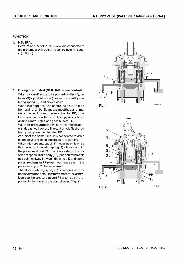
FUNCTION
RKS00820
1
T
P
fD
P2P1
Fig. 1
�������
�
�
�
�
��
�
�
�
�&
'
Fig. 2
1. NEUTRAL Ports P1 and P2 of the PPC valve are connected to drain chamber D through fine control hole f in spool (1). (Fig. 1)
2. During fine control (NEUTRAL → fine control)• When piston (4) starts to be pushed by disc (5), re-
tainer (9) is pushed; spool (1) is also pushed by me-tering spring (2), and moves down. When this happens, fine control hole f is shut off from drain chamber D, and at almost the same time, it is connected to pump pressure chamber PP, so pi-lot pressure oil from the control pump passes throu-gh fine control hole f and goes to port P1. When the pressure at port P1 becomes higher, spo-ol (1) is pushed back and fine control hole f is shut off from pump pressure chamber PP. At almost the same time, it is connected to drain chamber D to release the pressure at port P1. When this happens, spool (1) moves up or down so that the force of metering spring (2) is balanced with the pressure at port P1. The relationship in the po-sition of spool (1) and body (10) (fine control hole f is at a point midway between drain hole D and pump pressure chamber PP) does not change even if the pressure at port P1 becomes max. Therefore, metering spring (2) is compressed pro-portionally to the amount of movement of the control lever, so the pressure at port P1 also rises in pro-portion to the travel of the control lever. (Fig. 2)
10-66
R.H. PPC VALVE (PATTERN CHANGE) (OPTIONAL)
STRUCTURE AND FUNCTIONSK714-5 SK815-5 SK815-5 turbo

3. During fine control (when the lever is returned)
RKS00840
1
T
P
f
D
P2P1
4
5
9
2
PP
f
3
Fig. 3
(fine control → neutral)When disc (5) starts to be returned, spool (1) is pu-shed up by the force of centering spring (3) and the pressure at port P1. When this happens, fine control hole f is connected to drain chamber D and the pressure oil at port P1 is released. If the pressure at port P1 drops too far, spool (1) is pushed down by metering spring (2), and fine con-trol hole f is shut off from drain chamber D. At almost the same time, it is connected to pump pressure chamber PP, and the pump pressure is supplied until the pressure at port P1 recovers to a pressure that corresponds to the lever position. (Fig. 3).
SK714-5 SK815-5 SK815-5 turbo
R.H. PPC VALVE (PATTERN CHANGE) (OPTIONAL)
STRUCTURE AND FUNCTION10-67

L.H. PPC VALVE (STANDARD)
TRAVEL CONTROL
RKS00860
P2 P4
P1P3
EE
B
B
FF
AC
A C
DD
PT
P1 port - To hydraulic pump (DA2 port)P2 port - To hydraulic pump (DB1 port)P3 port - To hydraulic pump (DA1 port)P4 port - To hydraulic pump (DB2 port)P port - From solenoid valve group ST1 (B port)T port - To hydraulic tank
FUNCTIONP1 L.H. travel forwardP2 L.H. travel reverseP3 R.H. travel forwardP4 R.H. travel reverse★ When acting control lever, two ports are pressurized
contemporarily (i.e.: travel forward pressurize P1 and P3 ports).
10-68
L.H. PPC VALVE (STANDARD)
STRUCTURE AND FUNCTIONSK714-5 SK815-5 SK815-5 turbo

RKS00871
Section A - A
4
6
5 7
8
9
10
1
3
2
Section B - B
Section C - C
Section D - D
Section E - E
Section F - F
Section G - G
14
11
GG
12
13
1. Spool 2. Metering spring 3. Centering spring 4. Piston 5. Disc 6. Nut 7. Joint
8. Cover 9. Stopper10. Body11. Plug12. Ball13. Seat14. Body (for shuttle valve)
SK714-5 SK815-5 SK815-5 turbo
L.H. PPC VALVE (STANDARD)
STRUCTURE AND FUNCTION10-69

FUNCTION
RKS00890
1
T
P
fD
(P3) P2P1 (P4)
Fig. 1
��������
��(�)�*���)�
�
�
�
��
�
�
�
�&
��
Fig. 2
1. NEUTRAL Ports P1 and P2 of the PPC valve are connected to drain chamber D through fine control hole f in spool (1). (Fig. 1)
2. During fine control (NEUTRAL → fine control)• When piston (4) starts to be pushed by disc (5), re-
tainer (9) is pushed; spool (1) is also pushed by me-tering spring (2), and moves down. When this happens, fine control hole f is shut off from drain chamber D, and at almost the same time, it is connected to pump pressure chamber PP, so pi-lot pressure oil from the control pump passes throu-gh fine control hole f and goes from port P1. When the pressure at port P1 becomes higher, spo-ol (1) is pushed back and fine control hole f is shut off from pump pressure chamber PP. At almost the same time, it is connected to drain chamber D to release the pressure at port P1. When this happens, spool (1) moves up or down so that the force of metering spring (2) is balanced with the pressure at port P1. The relationship in the po-sition of spool (1) and body (10) (fine control hole f is at a point midway between drain hole D and pump pressure chamber PP) does not change even if the pressure at port P1 becomaes max. Therefore, metering spring (2) is compressed pro-portionally to the amount of movement of the control lever, so the pressure at port P1 also rises in pro-portion to the travel of the control lever. (Fig. 2)
10-70
L.H. PPC VALVE (STANDARD)
STRUCTURE AND FUNCTIONSK714-5 SK815-5 SK815-5 turbo

3. During fine control (when the lever is returned)
RKS00880
1
T
P
fD
P2P1
4
5
3
2
PP
f
Fig. 3
(fine control → neutral)When disc (5) starts to be returned, spool (1) is pu-shed up by the force of centering spring (3) and the pressure at port P1. When this happens, fine control hole f is connected to drain chamber D and the pressure oil at port P1 is released. If the pressure at port P1 drops too far, spool (1) is pushed down by metering spring (2), and fine con-trol hole f is shut off from drain chamber D. At almost the same time, it is connected to pump pressure chamber PP, and the pump pressure is supplied until the pressure at port P1 recovers to a pressure that corresponds to the lever position. (Fig. 3).
SK714-5 SK815-5 SK815-5 turbo
L.H. PPC VALVE (STANDARD)
STRUCTURE AND FUNCTION10-71

L.H. PPC VALVE - PATTERN CHANGE (OPTIONAL)
WORK EQUIPMENT AND TRAVEL CONTROL
RKS00800
AC
A C
EE
T
B
B
DD
P
P2 P4
P1P3
P1 port - To pattern change valve (Pin 1 port)P2 port - To pattern change valve (Pin 2 port)P3 port - To pattern change valve (Pin 4 port)P4 port - To pattern change valve (Pin 3 port)P port - From solenoid valve group ST1T port - To hydraulic tank
FUNCTION
ISO PATTERN: P1 Travel forwardP2 Travel reverseP3 L.H. travelP4 R.H. travel
OPTIONAL PATTERN: P1 L.H. travel forwardP2 L.H. travel reverseP3 Raise armP4 Lower arm
10-72
L.H. PPC VALVE - PATTERN CHANGE (OPTIONAL)
STRUCTURE AND FUNCTIONSK714-5 SK815-5 SK815-5 turbo

RKS00811
Section A - A
4
6
5 7
8
9
10
1
3
2
Section B - B
Section C - C
Section D - D
Section E - E
1. Spool 2. Metering spring 3. Centering spring 4. Piston 5. Disc 6. Nut
7. Joint 8. Cover 9. Stopper10. Body
SK714-5 SK815-5 SK815-5 turbo
L.H. PPC VALVE - PATTERN CHANGE (OPTIONAL)
STRUCTURE AND FUNCTION10-73

FUNCTION
RKS00820
1
T
P
fD
P2P1
Fig. 1
�������
�
�
�
�
��
�
�
�
�&
'
Fig. 2
1. NEUTRAL Ports P1 and P2 of the PPC valve are connected to drain chamber D through fine control hole f in spool (1). (Fig. 1).
2. During fine control (NEUTRAL → fine control)• When piston (4) starts to be pushed by disc (5), re-
tainer (9) is pushed; spool (1) is also pushed by me-tering spring (2), and moves down. When this happens, fine control hole f is shut off from drain chamber D, and at almost the same time, it is connected to pump pressure chamber PP, so pi-lot pressure oil from the control pump passes throu-gh fine control hole f and goes from port P1. When the pressure at port P1 becomes higher, spo-ol (1) is pushed back and fine control hole f is shut off from pump pressure chamber PP. At almost the same time, it is connected to drain chamber D to release the pressure at port P1. When this happens, spool (1) moves up or down so that the force of metering spring (2) is balanced with the pressure at port P1. The relationship in the po-sition of spool (1) and body (10) (fine control hole f is at a point midway between drain hole D and pump pressure chamber PP) does not change even if the pressure at port P1 becomaes max. Therefore, metering spring (2) is compressed pro-portionally to the amount of movement of the control lever, so the pressure at port P1 also rises in pro-portion to the travel of the control lever. (Fig. 2)
10-74
L.H. PPC VALVE - PATTERN CHANGE (OPTIONAL)
STRUCTURE AND FUNCTIONSK714-5 SK815-5 SK815-5 turbo

3. During fine control (when the lever is returned)
RKS00840
1
T
P
f
D
P2P1
4
5
9
2
PP
f
3
Fig. 3
(fine control → neutral)When disc (5) starts to be returned, spool (1) is pu-shed up by the force of centering spring (3) and the pressure at port P1. When this happens, fine control hole f is connected to drain chamber D and the pressure oil at port P1 is released. If the pressure at port P1 drops too far, spool (1) is pushed down by metering spring (2), and fine con-trol hole f is shut off from drain chamber D. At almost the same time, it is connected to pump pressure chamber PP, and the pump pressure is supplied until the pressure at port P1 recovers to a pressure that corresponds to the lever position. (Fig. 3).
SK714-5 SK815-5 SK815-5 turbo
L.H. PPC VALVE - PATTERN CHANGE (OPTIONAL)
STRUCTURE AND FUNCTION10-75
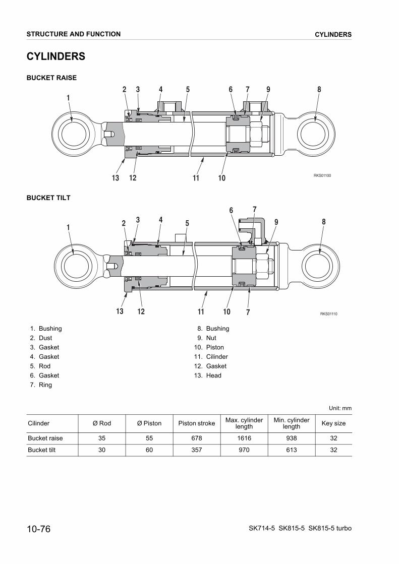
CYLINDERS
BUCKET RAISE
BUCKET TILT
RKS0110013 11 10
12 3 4 5 6 7 9 8
12
RKS0111013 11 10
1 2 3 4 5
6 7
9 8
12 7
1. Bushing 2. Dust 3. Gasket 4. Gasket 5. Rod 6. Gasket 7. Ring
8. Bushing 9. Nut10. Piston11. Cilinder12. Gasket13. Head
Unit: mm
Cilinder Ø Rod Ø Piston Piston stroke Max. cylinderlength
Min. cylinderlength Key size
Bucket raise 35 55 678 1616 938 32
Bucket tilt 30 60 357 970 613 32
10-76
CYLINDERS
STRUCTURE AND FUNCTIONSK714-5 SK815-5 SK815-5 turbo

10-77
12
AC
B
12
12RE STOPTCH
INTERRUTTORE BACK-UPBACK-UP SWITCH
ITCH
A ACQUA
DER
SW STOP
FUEL LEVELLIVELLO COMBUST.
BACK-UP
X23
X20
X17
X29
RKS03560
WIRES IN VIEWVISTA LATO FILI
21 34 5 6
X08
3
1
4
2
X07
1
3
2
X13
1 2
XS1
34 2 17 6 5
ELECTRICAL DIAGRAM (ENGINE LINE) (1/3)
SK714-5 S
ELECTR
TI
STRUCTUR
K815-5 SK815-5 turbo
ICAL DIAGRAM (ENGINE LINE) (1/3)
12
11
54
13
712
6
109
8
32
1
12
_I
1A
12
42
31
LATO FILI
36
14 5
2
LATO FILI
21
50
87
86
30
85
_I
12
20
POMPA GASOLIOFUEL PUMP
USCITA MASSEGROUND
DIODODIODE
RELE’ PULL SOLENOIDEPULL SOLENOID RELAY
START
ENGINE STOPARRESTO MOTORE
ENGINE STOP TIMERMER ARRESTO MOTORE
ALTERNATOREGENERATOR
INTERRUTTOSTOP SWI
INSULATORISOLATORE
ENGINE OIL PRESSURE SWPRESS. OLIO MOTORE
PREHEATINGPRERISCALDO
SALDATURA +15
INT.FILTRO OLIO IDR.HYDR. OIL FILTER SW.
SENSORE TEMPERATURENGINE WATER
TEMPERATURE SEN
BACK-UP ALARMSIRENA BACK-UP
AIR FILTERFILTRO ARIA
SAFETY RELAYRELE’ SICUREZZA
CONNECTORCONNETTORE
GND5
X06D
X03
XM1
X13
X07
X11
X21
XSX31
XR1
SA1
X26
X18
X14
X22
XB25X08
XS1
DIODODIODE
X06
CONNECTORCONNETTORE
X10
CONNECTORCONNETTORE
X02
CONNECTORCONNETTORE
X01
GENERATORALTERNATORE
XG2
GENERAL FUSE 50AFUSIBILE GENERALE 50A
XF1
STARTER MOTORMOTORINO AVV.
XB
TO INSULATORA ISOLATORE
XS2
21 20 1619 18 17 15 14 13 12 11 10 9 8
E AND FUNCTION

SK714-
ELEC
X281
S31
S29S28X20
L-R
1
X20
L-R
1
R-V
1
X21 X21
S30
Z-N
1
L-R
1
X22X22 X23X23
21 1 2 21 21
N1
HA3
X29X2912
Z-N
1
B-G1
R-G1
B-N1
S-G1
C-N1
C-L1
S1
B1
R2.5
R-V1
R-N1.5
L-R1
R4
GND5N4
X02
X10
X10
X10
X10
X10
X10
X10
X10
X10
X10
X10
X10
X02
X10
X01
X01
X01
X01
l
8
4
3
2
1
7
6
5
12
11
10
9
-
13
3
1
2
4R-N2.5
M2.5
p
pp p
TO F
RA
ME
LIN
E O
PT/S
TD
15 16 17 18 19 20
RKS03570
STRUCTURE AND FUNCTION ELECTRICAL DIAGRAM (ENGINE LINE) (2/3)
5 SK815-5
TRICA
FG150A
G1
1
10-78 SK815-5 turbo
L DIAGRAM (ENGINE LINE) (2/3)
N1
XF
S-N
1
G2
30D+
W
31
M130 50
N50
12Vcc
B2.
5
XB1
R50
X09
1
X11
1
X11
2
XM1
S1
R-G
1
XF
1
2
R6R6
S25R1
M2Y0
X11
3
N2.
5
B2.
5B
2
N2
R1.
5R
-N1.
5
R-G
1
N1
M2.
5
N1
C-L
1
K01 86 87
85 30
M-V
1
R6
L/B
1
M-V
1
R-N
1.5
L/B
1
R-N
1.5
R-N
2.5
R-N
1.5
R6B2
N1
V1
R-B
1
X07
X07
G1
X07
X07
N1
R1
N1
K02
XS
R4
S26 S27R3R2
B-N
1
N1
X13X13 X13 X15X14X14 X16X16 X19X17 X17 X18 X18
13 2 1+- 12 1C A - +
C-N
1
S-G
1
R-G
1
S-N
1
B2.
5 B1
N1
X03 X06X03X03 X03 X06 XS1 X08XS1 X08X08 X0886 -8785 30 l 34 12 A 1B 53 6
U3
GMpM
ENGINE YANMAR PARTS
POW
ERB
OX
K03
p p
t
RELAYSAFETY
2 3 4 5 6 7 8 9 10 1211 13 14

10-79
ELECTRICAL DIAGRAM (ENGINE LINE) (3/3)
SK714-5 S
ELECTR
COMPONENFG1 GeneG1 BatterG2 GeneK01 Fuel sK02 Fuel pK03 SafetyM1 StarteM2 Fuel pR1 PreheR2 Fuel lR3 EnginS25 Air filtS26 HydraS27 Stop lS28 Stop lS29 Back-S30 Back-S31 EnginV1 DiodeX01 FrameX02 2 wayX03 Fuel sX06 DiodeX07 Pull sX08 SafetyX09 C6 geX10 FrameX11 GeneX13 Fuel pX14 Fuel pX15 PreheX16 Air filtX17 Fuel lX18 EnginX19 HydraX20 Stop lX21 Stop lX22 Back-X23 Back-Y0 Stop f
STRUCTUR
K815-5 SK815-5 turbo
ICAL DIAGRAM (ENGINE LINE) (3/3)
TSral fuse 50Ay 80Ahratorolenid valve relayull solenid valve timer 1 second relayr motorumpating starterevel sendere water temperature senderer blocked switchulic oil filter blocked switchights pressure switchights pressure switchup alarm pressure switchup alarm pressure switche oil min. pressure switch 1A line 3 way connector connectorolenoid relay connector 2 way connectorolenoid timer 4 way connector relay 6 way connectornerator terminal line mark 13 way connector
rator 3 way connectorool-stop solenoid 3 way connector solenoid 3 way connectorump 2 way connectorating start C6 terminaler blocked switch 2 way connectorevel sender 3 way connectore water temperature sender 2 way connectorulic oil filter blocked switch C5 terminalight pressure 1 switch 2 way connectoright pressure 2 switch 2 way connectorup pressure 1 switch 2 way connectorup pressure 2 switch 2 way connectoruel solenoid valve
E AND FUNCTION

PAGE INTENTIONALLYLEFT BLANK
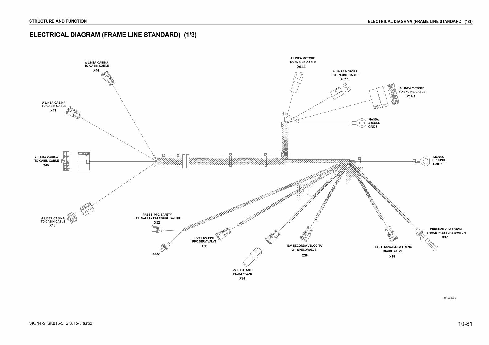
10-81
81
76
54
32
109
1312
11
ELETTROVALVOLA FRENOBRAKE VALVE
'
PRESSOSTATO FRENOBRAKE PRESSURE SWITCH
GROUNDMASSA
A LINEA MOTORETO ENGINE CABLE
TO ENGINE CABLEA LINEA MOTORE
MASSAGROUND
X35
X37
GND2
X10.1
X02.1
GND5
RKS03230
ELECTRICAL DIAGRAM (FRAME LINE STANDARD) (1/3)
SK714-5 S
ELECTR
A LINETO CAB
A LINETO CA
TO CABIN CA LINEA CA
X45
X
STRUCTUR
K815-5 SK815-5 turbo
ICAL DIAGRAM (FRAME LINE STANDARD) (1/3)
2
4
1
35
11 5
8 1
109
32
4
1213
67
E/V FLOTTANTE
PPC SERV. VALVE
FLOAT VALVE
E/V SERV. PPC
A CABINAIN CABLE
2nd SPEED VALVEE/V SECONDA VELOCITA
A CABINABIN CABLE
ABLEBINA
A LINEA CABINATO CABIN CABLE
A LINEA MOTORETO ENGINE CABLE
PPC SAFETY PRESSURE SWITCHPRESS. PPC SAFETY
X33
X34
48
X36
X47
X46X01.1
X32A
X32
E AND FUNCTION
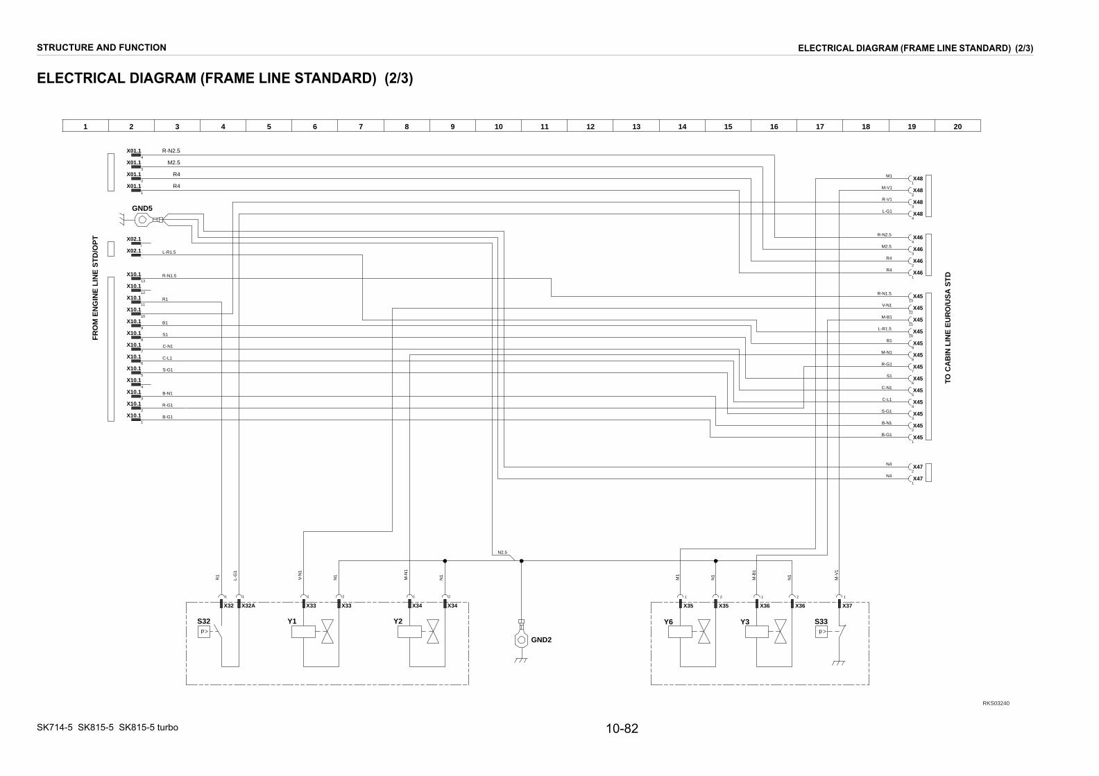
SK714-
ELEC
15 16 17 18 19 20
Y3 S33
2 1 2
35 X36 X36 X37
1
N1
M-B
1
M-V
1
X45
X45
X47
X45
X45
X45
X45
X45
X45
X45
X45
X45
X45
X45
X46
X46
X46
X48
X48
X48
X48
X46
X472
1
2
5
6
7
8
9
10
11
12
13
2
3
4
4
3
2
1
1
3
4
1
V-N1
M2.5
B-G1
R-G1
L-R1.5
S-G1
C-L1
C-N1
S1
B1
R-N1.5
R-V1
M-N1
M-B1
R-N2.5
B-N1
M1
M-V1
L-G1
N4
R4
R4
N4
p
TO C
AB
IN L
INE
EU
RO
/US
A S
TD
RKS03240
STRUCTURE AND FUNCTION ELECTRICAL DIAGRAM (FRAME LINE STANDARD) (2/3)
5 SK815-5
TRICA
1
FR
OM
EN
GIN
E L
INE
ST
D/O
PT
10-82 SK815-5 turbo
L DIAGRAM (FRAME LINE STANDARD) (2/3)
2 3 4 5 6 7 8 9 10 1211 13 14
Y1 Y2 Y6S32
B-N1
S-G1
C-L1
C-N1
S1
B1
R1
M2.5
B-G1
R-G1
X32AX32
L-G
1
R1
V-N
1
X33 X33 X34 X34
11 1 2 1 2
M-N
1
N1
N1
1
X35 X
N1
M1
R-N1.5
R-N2.5
L-R1.5
GND2
X02.1
X02.1
X01.1
X01.1
X01.1
X10.1
X10.1
X10.1
X10.1
X10.1
X10.1
X10.1
X10.1
X10.1
X10.1
X10.1
X10.1
X10.1
X01.1
-
l
2
3
4
1
2
3
4
5
6
7
8
9
10
11
12
13
1
R4
R4
N2.5
GND5
p

10-83
ELECTRICAL DIAGRAM (FRAME LINE STANDARD) (3/3)
SK714-5 S
ELECTR
COMPONGND2 C8 gGND5 C6 gS32 PPCS33 BrakX01.1 EngiX02.1 EngiX10.1 EngiX32 PPCX32A PPCX33 PPCX34 FloaX35 BrakX36 SecoX37 BrakX45 CabX46 CabX47 GrouX48 CabY1 PPCY2 FloaY3 SecoY6 Brak
STRUCTUR
K815-5 SK815-5 turbo
ICAL DIAGRAM (FRAME LINE STANDARD) (3/3)
ENTSround terminalround terminal safety pressure switche valve pressure switchne line 4 way connectorne line 2 way connectorne line 13 way connector safety pressure switch 1 way connector safety pressure switch 1 way connector valve 2 way connectort valve 2 way connectore valve 2 way connectornd speed valve 2 way connectore pressure switch 1 way connectorin line 13 way connectorin line 4 way connectornd 2 way connector
in line 5 way connector valvet valvend speed valvee valve
E AND FUNCTION

PAGE INTENTIONALLYLEFT BLANK

10-85
81
76
54
32
109
1312
11
ELETTROVALVOLAFRENO
BRAKE VALVEE/V HI-FLOWMOMENTARY
I-FLOW MOMENTARYVALVE
HI-FLOW DETENTVALVE
E/V HI-FLOWDETENT
MASSAGROUND
GROUNDMASSA
OTORE CABLE
A LINEA MOTORETO ENGINE CABLE
TO ENGINE CABLEA LINEA MOTORE
BRAKE PRESSURESWITCH
PRESSOSTATOFRENO
MASSAGROUND
X35
X40 X39
GND 1
GND 2
1
X10.1
X02.1
X37
GND 5
RKS03250
ELECTRICAL DIAGRAM (FRAME LINE OPTIONAL) (1/3)
SK714-5 S
ELECTR
A LINEA CTO CABIN
ATO
TO CABIN CABA LINEA CABI
X45
X48
STRUCTUR
K815-5 SK815-5 turbo
ICAL DIAGRAM (FRAME LINE OPTIONAL) (1/3)
2
4
1
3
5
9 4
23
87
1
56
1110
11 5
8 1
109
32
4
1213
67
2
4
13
5
TO CABIN CABLEA LINEA CABINA
PPC SERV. VALVEE/V SERV. PPC
ABINA CABLE
2nd SPEEDVALVE
E/V SECONDAVELOCITA'
H
LINEA CABINA CABIN CABLE
LENA
A LINEA CABINATO CABIN CABLE
A LINEA MOTORETO ENGINE CABLE
A LINEA MOTORETO ENGINE CABLE
A LINEA M
A LINEA MOTORETO ENGINE CABLE
TO ENGINE
FLOAT VALVEE/V FLOTTANTE
PRESS. PPC SAFETYPPC SAFETY PRESSURE SWITCH
X49
X33
X36
X47
X46
X41
X43
X42
X01.
X34
X32
X32A
E AND FUNCTION

SK714-
ELEC
15 16 17 18 19 20
Y3 S33
N1
X35
2
X36
1
X36
2
M-B
1
X37
1
M-V
1
X47
X47
X49
X49
X49
X49
X49
X49
X49
X49
X49
X49
X49
X45
X45
X45
X45
X45
X45
X45
X45
X45
X45
X45
X45
X45
X46
X46
X46
X48
X48
X48
X48
X46
2
1
1
5
3
2
4
7
6
8
9
12
10
11
13
1
2
3
4
5
6
7
8
9
10
11
2
3
4
1
2
3
4
1
N4
C1
C-B1
V1
V-B1
A-V1
Z-N1
A-B1
A-N1
A-G1
B-N1
R-G1
S1
C-N1
C-L1
S-G1
B-G1
M-N1
B1
M-B1
V-N1
R-N1.5
M2.5
R-N2.5
L-G1
R-V1
M-V1
M1
L-R1.5
R4
R4
L-R1.5
S-N1.5
N4
p
TO C
AB
IN L
INE
EU
RO
/US
A O
PT
RKS03260
STRUCTURE AND FUNCTION ELECTRICAL DIAGRAM (FRAME LINE OPTIONAL) (2/3)
5 SK815-5
TRICA
1
C-B
1
FR
OM
EN
GIN
E L
INE
ST
D/O
PT
10-86 SK815-5 turbo
L DIAGRAM (FRAME LINE OPTIONAL) (2/3)
2 3 4 5 6 7 8 9 10 1211 13 14
Y1 Y2 Y6S32
B-N1
S-G1
C-L1
C-N1
B1
R-V1
M2.5
B-G1
R-G1
X32A
1
X32
1
L-G
1
V-N
1
X33
1
X33
2
X34
1
X34
2
M-N
1
N1
N1
N1
X35
1
R-N1.5
R-N2.5
Y5 Y4
X39
1
X39
2
X40
1
X40
2
N1
N1Z-N
1
A-V
1
A-B
1
A-N
1
V1
V-B
1
C1
A-G
1
X41
X41
X41
X41
S1
X42
X42
X42
M1
N4
GN
D2
GN
D1
X43
X42
X42
1234 123 145
N1.
5
L-R1.5
N2.5
X10.1
X10.1
X10.1
X10.1
X10.1
X10.1
X10.1
X10.1
X10.1
X10.1
X10.1
X10.1
X10.1
X01.1
X01.1
X01.1
X02.1
X02.1
X01.1
1
2
3
4
5
6
7
8
9
10
11
12
13
2
3
4
-
l
1
R4
R4
R2.5R
2.5
L-R
1.5
S-N
1.5
GND5
p
( POWER BOX ATTACH. LINE )
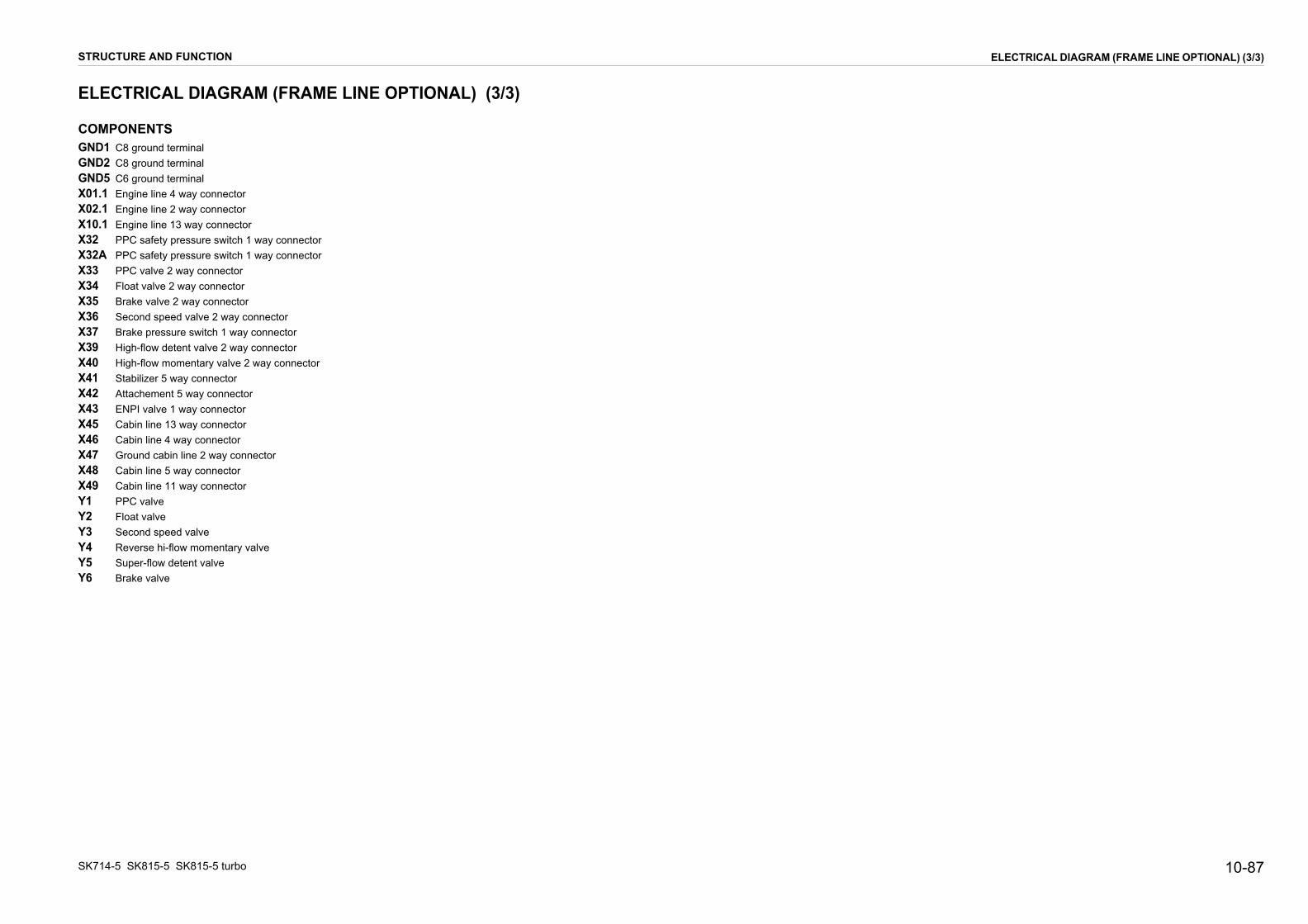
10-87
ELECTRICAL DIAGRAM (FRAME LINE OPTIONAL) (3/3)
SK714-5 S
ELECTR
COMPONGND1 C8 gGND2 C8 gGND5 C6 gX01.1 EngiX02.1 EngiX10.1 EngiX32 PPCX32A PPCX33 PPCX34 FloaX35 BrakX36 SecoX37 BrakX39 HighX40 HighX41 StabX42 AttacX43 ENPX45 CabX46 CabX47 GrouX48 CabX49 CabY1 PPCY2 FloaY3 SecoY4 ReveY5 SupeY6 Brak
STRUCTUR
K815-5 SK815-5 turbo
ICAL DIAGRAM (FRAME LINE OPTIONAL) (3/3)
ENTSround terminalround terminalround terminalne line 4 way connectorne line 2 way connectorne line 13 way connector safety pressure switch 1 way connector safety pressure switch 1 way connector valve 2 way connectort valve 2 way connectore valve 2 way connectornd speed valve 2 way connectore pressure switch 1 way connector-flow detent valve 2 way connector-flow momentary valve 2 way connectorilizer 5 way connectorhement 5 way connectorI valve 1 way connectorin line 13 way connectorin line 4 way connectornd cabin line 2 way connector
in line 5 way connectorin line 11 way connector valvet valvend speed valverse hi-flow momentary valver-flow detent valve
e valve
E AND FUNCTION

PAGE INTENTIONALLYLEFT BLANK

10-89
01171077
ENTRALINA SICUREZZE
ONTROL PANEL
PANNELLOI CONTROLLO
MANIPOLATORE DXRIGHT LEVER
SAFETY CONTROL BOX
BRAKE BUTTONPULSANTE FRENO INT. GIROFARO
BEACON LIGHT SWITCH
SENSORE BRACCIOLO
MANIPOLATORE SXLEFT LEVER
PROXIMITY BAR 3 WAY
ZOCCOLO RELE' FLOATFLOAT RELAY SOCKET
PARKING RELAYRELE' PARKING
X80
CONTROL PANEL
PANNELLODI CONTROLLO
X81
X84
X50
X87 X88
K04
X54
X83
K14
RKS03270
ELECTRICAL DIAGRAM (CABIN LINE STANDARD) (1/5)
SK714-5 S
ELECTR
FROM FRAME
DA LINEA TFROM FRAM
DA LINEA TE
FRODA
X45.1
X46.1
STRUCTUR
K815-5 SK815-5 turbo
ICAL DIAGRAM (CABIN LINE STANDARD) (1/5)
9 4
238
71
56
1110
81
76
54
32
109
1312
11
5
43
21
5
6
1
9
2
7
8
10
3
11
4
C
SWITCH SEDILE
GNDGROUND
CABIN LINECABINA
CD
INT. FARO LAVORO POST.REAR WORK LIGHTS SWITCH
SAFETY SEAT SWITCH
INT. LUCIFRONT LIGHTS SWITCH
LINE
ELAIOE LINE
LAIO
M FRAME LINELINEA TELAIO
BUZZERBUZZER
QUADRO AVVIAMENTOSTARTING SWITCH
ACCENDISIGARICIGARETTE LIGHTER
SCATOLA FUSIBILIFUSES BOX
MASSEGROUND
X82
X85
X55
X86
X48.1
X52-X53
X78-79
S10
X47.1
X56-X77
GND3
E AND FUNCTION

SK714-
C
15 16 17 18 19 20
FU07
10A
FU05
15A
FU04
7.5A
FU03
15A
FU02
3A
H-R
2.5
H-R
2.5
H-R
2.5
R2.
5
X641
X651
X661
X671
X681
X691
X701
X711
X721
X731
X741
X751
X761
X771
B/N
1
M-B
1
M/B
1
H/R
1
A-R
1.5
G/R
1
G-N
1
M-V
1
X81
X81
X81
X81
X81
X81
X81
X81
1 2 3 4 5 6 7 8
M-N
1
H-R
2.5
H0.
5
G/N
1
B-R
1
FU06
10A
FU01
3A
B-R1
G1.5
L/B1
A-R1.5
H-R1
H-R1.5
B-R1
H-R1
G/R1
N4
H0.5
A/B1
L/G1
S/N1
C1
B/R1
B-N1
M-N1
H/R1
G1
G-N1
CK)
K
RKS03280
STRUCTURE AND FUNCTION ELECTRICAL DIAGRAM (CABIN LINE STANDARD) (2/5)
5 SK815-5
TRICA
1
1
X47.1
X47.12
EL
EC
TR
ON
IC U
NIT
FR
OM
FR
AM
E L
INE
ST
D
06
GND
BRAKE P.B.
HI-SPEED P. B.
FLOAT P. B.
SAF. BAR. SW
SEAT SWITCH
POW. SUPP.
EV BRAKE
STOP ENGINE
BRAKE LIGHT
SAF. BAR.LED
SEAT LED
WARNING LED
FLOAT
BUZZER
HI-SPEED
GND
HORN
START SIGN.
+12V HORN
HORN PUSH B.
PPC SAF. SW.
EV PPC
BUZZER
IN
IN
IN
IN
IN
+1
OU
OU
OU
OU
OU
OU
OU
OU
OU
OU
IN
IN
IN
OU
OU
10-90 SK815-5 turbo
L DIAGRAM (CABIN LINE STANDARD) (2/5)
2 3 4 5 6 7 8 9 10 1211 13 14
S10
R1 ACC BR R2 C
B
B-G1
B-N1
S-G1
C-L1
C-N1
S1
R-G1
L-R1.5
M-B1
V-N1
R-N1.5
R4
M2.5
R-N2.5
M1
L-G1
FU11
30A
FU10
7.5A
FU09
7.5A
FU08
10A
H-R
2.5
H-R
2.5
H-R
2.5
S11S12
H-R
2.5
M2.
5
B1
B1
R-N1.5
R4
HA1 R-N2.5
C-N
1
N1
B-N
1
B1
H-R
1
G-N
1
S-G
1
M1
C-L
1
S1
X521
X531
X54 X54X54X55X55A BC
12
X561
X571
X581
X591
X601
X611
X621
X631
C/N
1
N1
H-R
1
C-B
1
H-R
1
H-R
1
L-R
1.5
B-G
1
R-G
1
R-N
2.5
R/N1
M-V1
X80
X80
X80
X80
X80
X80
X80
X80
X80
X80
X80
X80
X80
X80
X80
X80
1 2 3 4 5 6 7 8 9 10 11 12 13 14 15 16
N4
1
2
3
4
5
6
7
8
9
10
11
12
13
1
2
3
1
2
3
4
M-N1
Z-B
1
X501
X502
X503
X504
X505
X506
X507
X508
X509
X5010
X5011
X5012
X5013
X5014
X5015
X5016
X5017
X5018
X5019
X5020
X5021
X5022
X5023
Z-B
1
K14 86 87a 87
85 30
X44 86
X44 87a
X44 30
X44 85
M1
H-L1
M-B1
N1.5
B/N1
C-B1
C/N1
R/N1
M/B1
A/B1
Z-B1
G/N1
L/G1
L/B1
S/N1
B-N1
C1
B1
L-G1
V-N1
B/R1
H-R1.5
H-R1
H-L1
B-G1
4
R4
X45.1
X45.1
X45.1
X45.1
X45.1
X45.1
X45.1
X45.1
X45.1
X45.1
X45.1
X45.1
X45.1
X46.1
X46.1
X46.1
X48.1
X48.1
X48.1
X48.1
X46.1
R1ST
OFF ACC
CONTROL PANEL (UNIDE
P1
2V
T
T
T
T
T
T
T
T (-)
T
T
T
T (+)
ELE

10-91
15 16 17 18 19 20
S02 1 6 8 9
3 2 10
S07
1 9
5 10
S01
1 9
5 10
X833
G/R1
G/R1
G1.5
A-G1.5
H-N1
H-G1
H/R1
A-R1.5
H-R1
N1
N1
S08
15/1 30/3 L/6
49/4 30b/2 R/7
L/B1
G/R1
N1
X85
X85
X85
X85
X86
X86
X86
X86
X86
X86
X87
X87
X87
X87
X88
X88
X88
X88
9
1
5
10
9
8
1
3
2
10
6
3
2
7
9
1
5
10
S/N1
S15
X841
X843
L/G
1L/
G0.
5
R-N
0.5
B-R
1
H-R1
H-R1
H-R1.5
X8311
X8411
N1
N1
0 21
1 0
1 0
10
RIG
HT
LE
VE
R
RKS03290
ELECTRICAL DIAGRAM (CABIN LINE STANDARD) (3/5)
SK714-5 S
ELECTR
1
STRUCTUR
K815-5 SK815-5 turbo
ICAL DIAGRAM (CABIN LINE STANDARD) (3/5)
2 3 4 5 6 7 8 9 10 1211 13 14
H-R1.5
A-R1.5
A/B1
B-R1
B-R1
H-R1
K04 85 87
86 30
S13 S14
G/R1
N4
G1.5
H-R1
C1
X831
X832
A/B
1
B/R
1
H-N
1
H-N
1
H-G
1
N1.
5
X89 X89 X89
V/B
0.5
L/G
0.5
H0.5
L/B1
L/G1
S/N1
C1
B/R1
B-N1
M-N1
A-G
1.5
1 2 3 4 5 6 7 8 9 10
X82
X82
X82
X82
X82
X82
X82
X82
X82
X82
X82
11
X8986 30 8785
B-R
1
M-N
1
B-N
1
B-R
1
GND3
R-N
0.5
H/R1
B-R
1
G1
G-N
1
G-N1
X781
X791
H/R
1
N1
TO TOP CABIN LINE STD
LE
FT
LE
VE
R
E AND FUNCTION

SK714-
ELEC
15 16 17 18 19 20
X81
-1
X81
-8
X81
-6
X81
-5
X81
-4
X81
-3
X81
-2
X81
-7X
80-1
1
X80
-14
X80
-12
X80
-16
X80
-15
L7L6 L8
TOREMP.
L1 L2
L10L9DL1 DL3DL2
L4L3 L5
RKS03300
STRUCTURE AND FUNCTION ELECTRICAL DIAGRAM (CABIN LINE STANDARD) (4/5)
5 SK815-5
TRICA
1
L6
L7
+50
POS.
DL3
L8
+15
GND
GND
C2
C3
POS.
X
X
X
X
X
X
X
X
X
X
X
X
10-92 SK815-5 turbo
L DIAGRAM (CABIN LINE STANDARD) (4/5)
2 3 4 5 6 7 8 9 10 1211 13 14
CONTROL PANEL (EXTERNAL WIEW)
DL2L6
C1
L8L7 L9 L10
C
H
L1 L3L2 L4 L5 C2
DL1 DL3
E
F
C3
X80-9 X80-2 X80-3
INTERNAL CONNECTION CONTROL PANEL
X80-8
-
HOUR COUNTER
X80-6
C1
+
LEVEL
C2
FUEL
C3
INDICAWATER T
PARKING BRAKE LAMP
SECOND SPEED LAMP81-4
81-3
M-B1
M-V1NEGATIVE
POSITIVE
DL1
DL2
WARNING LED
SEAT LED
X81-7
X81-8 G/N1
M/B1NEGATIVE
NEGATIVE
X80-11
X80-10
X80-12
X80-14
X80-13
X80-15
X80-16
B1 L2+5080-4 START SIGNAL
FUNCTION
SAFETY BAR OPEN LED
FLOAT LAMP
PIN
81-1
81-2
POWER SUPPLY (+12V)80-8
80-7
80-6
80-5
GROUND
GROUND
M-N1
B/N1
WIRE COLOURSIGNAL
NEGATIVE
POSITIVE
POS.
L9
L10
H-R1+15
GND
GND
L1
L3
N1 L4
FUNCTION
FUEL LEVEL INDICATOR
WATER TEMPERAT. INDICATOR
80-2
80-3
PIN
80-1
C-N1
B-N1
WIRE COLOUR
ohm
ohm
SIGNAL
L5
POS.
M1POSITIVEPREHEATING LAMP
LOW BEAM LAMP
FUNCTION
DIRECTION LAMP
PIN
X81-5
X81-6
AIR FILTER LAMP
GENERATOR LAMP
ENGINE OIL PRESSURE LAMP
H0.5
L-N1
WIRE COLOURSIGNAL
POSITIVE
POSITIVE
B-G1
S1
C-L1
NEGATIVE
NEGATIVE
NEGATIVE
INTERNAL LIGHTS (+ LUCI)
HYDRAULIC OIL FILTER LAMP
FUNCTION
BUZZER
PIN
X80-9
S-G1
Z-B1
G-N1
WIRE COLOUR
NEGATIVE
NEGATIVE
SIGNAL
POSITIVE
P1
h0000000

10-93
CGFFFFFFFFFFFHKKKPSSSSSSSSSSXXXXXXXXXXXXXXXXXX
rr
orr
itch connector
ELECTRICAL DIAGRAM (CABIN LINE STANDARD) (5/5)
SK714-5 S
ELECTR
OMPONND3 C6 gU01 FuseU02 FuseU03 FuseU04 FuseU05 FuseU06 FuseU07 FuseU08 FuseU09 FuseU10 FuseU11 FuseA1 Warn04 Floa06 Elec14 Brak1 Cont01 Rear02 Pane07 Beac08 Brak10 Start11 Safe12 Bar P13 Horn14 Seco15 Floa44 Brak45.1 From46.1 From47.1 From48.1 From50 Elec52 Buzz53 Buzz54 Prox55 Safe56 Fuse57 Fuse58 Fuse59 Fuse60 Fuse61 Fuse62 Fuse63 Fuse
STRUCTUR
K815-5 SK815-5 turbo
ICAL DIAGRAM (CABIN LINE STANDARD) (5/5)
ENTSround terminal 3A left side lights 3A control panel lights 15A horn, front work lights 7.5A switch lights 15A rear work light 10A lever switch power supply, float 10A current intake 12V, beacon light 10A control panel, electronic unit, fuel shut off, safety bar proximity, seat safety switch, brake switch 7.5A back-up alarm 7.5A fuel pump, safety engine relay, generator 30A pull solenoid, PPC safety pressure switching buzzer
t relaytronic unite relayrol panel work lights switchl lights and low beam lights switchon light switche switching switchty seat switchNP safety sensor
push buttonnd speed push button
t push buttone relay connector frame line 13 way connector frame line 4 way connector frame line 2 way ground connector frame line 5 way connector
tronic unit 23 way connectorer 1 way connectorer 1 way connectorimity bar 3 way connectorty seat switch 3 way connector 1 way connector 1 way connector 1 way connector 1 way connector 1 way connector 1 way connector 1 way connector 1 way connector
X64 Fuse 1 way connectorX65 Fuse 1 way connectorX66 Fuse 1 way connectorX67 Fuse 1 way connectorX68 Fuse 1 way connectorX69 Fuse 1 way connectorX70 Fuse 1 way connectorX71 Fuse 1 way connectorX72 Fuse 1 way connectorX73 Fuse 1 way connectorX74 Fuse 1 way connectorX75 Fuse 1 way connectorX76 Fuse 1 way connectorX77 Fuse 1 way connectorX78 Current intake 1 way connectoX79 Current intake 1 way connectoX80 Control panel 16 way connectX81 Control panel 8 way connectoX82 Lights line 11 way connectorX83 Left lever 12 way connectorX84 Right lever 12 way connectorX85 Rear work lights SWF switchX86 Panel and front lights SWF swX87 Brake switch connectorX88 Beacon light switch connectorX89 Float relay connector
E AND FUNCTION

PAGE INTENTIONALLYLEFT BLANK

10-95
10
20
11
217 17
89
1819
56
16132
34
1415
1 12
01171077
ENTRALINA SICUREZZE
ONTROL PANELELLO DI CONTROLLO
E DXR
AFETY CONTROL BOX
LEFT STAB. SWITCH
CONTROL PANELPANNELLO DI CONTROLLO
BRAKE BUTTONPULSANTE FRENO
INT. STAB. DX
INT. GIROFAROBEACON LIGHT SWITCH
SENSORE BRACCIOLO
INT. STAB SX
MANIPOLATORE SXLEFT LEVER
PROXIMITY BAR 3 WAY
CENTRALINA COMANDO RELE'
ZOC. RELE' FLOATFLOAT RELAY S.
RELAY COMAND UNIT
PARKING RELAYRELE' PARKING
ARDARD
RELE' SPEGN. LUCI STOPSTOP LIGHT OFF RELAY
X80
X50
X81X87
X106
X107
X88
K04
X54
X83
X90
K14 K95
RKS03310
ELECTRICAL DIAGRAM (CABIN LINE OPTIONAL) (1/7)
SK714-5 S
ELECTR
FROM
DA LINEFROM FR
DA L
FROM FRAMDA LINEA TE
SOLDERSTAGNA
X4
X48.1
SA
STRUCTUR
K815-5 SK815-5 turbo
ICAL DIAGRAM (CABIN LINE OPTIONAL) (1/7)
9 4
238
71
56
1110
71
10
98
5
23
411
6
81
76
54
32
109
1312
11
5
43
21
5
6
1
9
2
7
8
10
3
11
4
3
3
15
10
10
7.5
30
10
10
10
15
C
SWITCH SEDILE
GNDGROUND
CABIN LINECABINA
CPANN
INT. FARO LAVORO POST.REAR WORK LIGHTS SWITCH
SAFETY SEAT SWITCH
INT. LUCIFRONT LIGHTS SWITCH
FRAME LINE
A TELAIOAME LINE
INEA TELAIO
E LINELAIO
FROM FRAME LINEDA LINEA TELAIO
BUZZERBUZZER
QUADRO AVVIAMENTOSTARTING SWITCH MANIPOLATOR
RIGHT LEVE
INT. E.V. ENPIENPI VALVE SWITCH
PRESA DI CORRENTECURRENT INTAKE
SCATOLA FUSIBILIFUSES BOX
S
SWITCH HAZSWITCH HAZ
INT. LUCI DIREZIONEDIRECTION LIGHTS SWITCH
MASSEGROUND
JOINTTURA
X82
X85
X55
X86
5.1
X46.1
X49.1
X52-X53
X78-X79
S10 X84
X91
X105
X104
X47.1
X56-X77
GND3
L
E AND FUNCTION
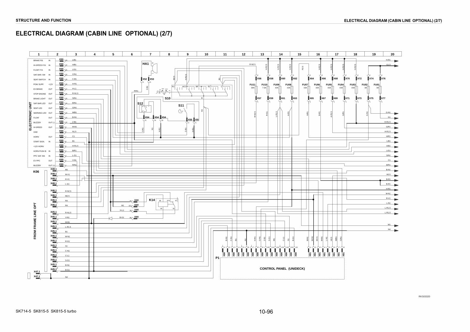
SK714-
C
FU05 FU04 FU03 FU02
1 1 1 1 1 1 1
X64 X66 X68 X70 X72 X74 X76
X65 X67 X69 X71 X73 X75 X771 1 1 1 1 1 1
1 2 3 4 5 6 7 8
FU06
FU0115A 10A 15A 3A10A 3A
B/N
1
M-B
1
M/B
1
M-V
1
M-N
1
H0.
5
G/N
1
L-N
1
16 17 18 19 20
H/R
1
A-R
1.5
G/R
1
G-N
1
B-R
1
B-R1
G1.5
L/B1
A-R1.5
H-R1
H-R1.5
B-R1
H-R1
G/R1
N4
H0.5
A/B1
L/G1
S/N1
C1
B/R1
B-N1
M-N1
H/R1
G1
G-N1
L-N1
R-V1
L-R1.5
L-R1.5
M1
H-R
2.5
H-R
2.5
H-R
2.5
H-R
2.5
X81
X81
X81
X81
X81
X81
X81
X81
RKS03320
STRUCTURE AND FUNCTION ELECTRICAL DIAGRAM (CABIN LINE OPTIONAL) (2/7)
5 SK815-5
TRICA
1
X47.1
X47.1
1
2
FR
OM
FR
AM
E L
INE
OP
T
K06
EL
EC
TR
ON
IC U
NIT
BRAKE P.B.
HI-SPEED P. B.
FLOAT P. B.
SAF. BAR. SW
SEAT SWITCH
POW. SUPP.
EV BRAKE
STOP ENGINE
BRAKE LIGHT
SAF. BAR.LED
SEAT LED
WARNING LED
FLOAT
BUZZER
HI-SPEED
GND
HORN
START SIGN.
+12V HORN
HORN PUSH B.
PPC SAF. SW.
EV PPC
BUZZER
10-96 SK815-5 turbo
L DIAGRAM (CABIN LINE OPTIONAL) (2/7)
S10
R1 ACC BR R2 C
B
FU11 FU10 FU09 FU08 FU07
S11S12
H-R
2.5
M2.
5
B1
R4
HA1
X52 X53
X54 X54X54X55X55
1 1
A BC
12
1 1 1 1
X56 X58 X60 X62
X57 X59 X61 X631 1 1 1
C/N
1
N1
H-R
1
C-B
1
H-R
1
R/N1
1 2 3 4 5 6 7 8 9 10 11 12 13 14 15 16
2
1
2
3
4
5
6
7
8
9
10
11
12
13
14
15
16
17
18
19
20
21
22
23
Z-B
1
K14 86 87a 87
85 30
X44
X44
X44
X44
86
87a
30
85
H-L1
M-B1
R-N1.5
N1.5
B/N1
C-B1
C/N1
R/N1
M/B1
A/B1
Z-B1
G/N1
L/G1
L/B1
S/N1
B-N1
C1
B1
L-G1
V-N1
B/R1
H-R1.5
H-R1
H-L1
B-G1
30A 7.5A 10A 10A 10A
C-N
1
N1
B-N
1
B1
H-R
1
G-N
1
S-G
1
M1
C-L
1
S1
B-G
1
Z-B
1
2 3 4 5 6 7 8 9 10 1211 13 14 15
H-R
1
R-G
1
R-N
2.5
L-R
1.5
X45.1
X45.1
X45.1
X45.1
X45.1
X45.1
X45.1
X45.1
X45.1
X45.1
X45.1
X45.1
X45.1
X46.1
X46.1
X46.1
X48.1
X48.1
X48.1
X48.1
X46.1
1
3
4
5
6
7
8
9
10
11
12
13
1
3
4
1
2
3
4
2
B-G1
B-N1
S-G1
C-L1
C-N1
S1
R-G1
L-R1.5
M-B1
V-N1
R-N1.5
R4
M2.5
R-N2.5
L-G1
B1
M-V1
N4
M-N1
R-V1
R4
M1
M1
R1ST
OFF ACC
H-R
2.5
H-R
2.5
H-R
2.5R-N2.5
R2.
5
CONTROL PANEL (UNIDECK)
X80
X80
X80
X80
X80
X80
X80
X80
X80
X80
X80
X80
X80
X80
X80
X80
P1
X50
X50
X50
X50
X50
X50
X50
X50
X50
X50
X50
X50
X50
X50
X50
X50
X50
X50
X50
X50
X50
X50
X50IN
IN
IN
IN
IN
+12V
OUT
OUT
OUT
OUT
OUT
OUT
OUT
OUT (-)
OUT
OUT
IN
IN
IN
OUT
OUT (+)
ELE
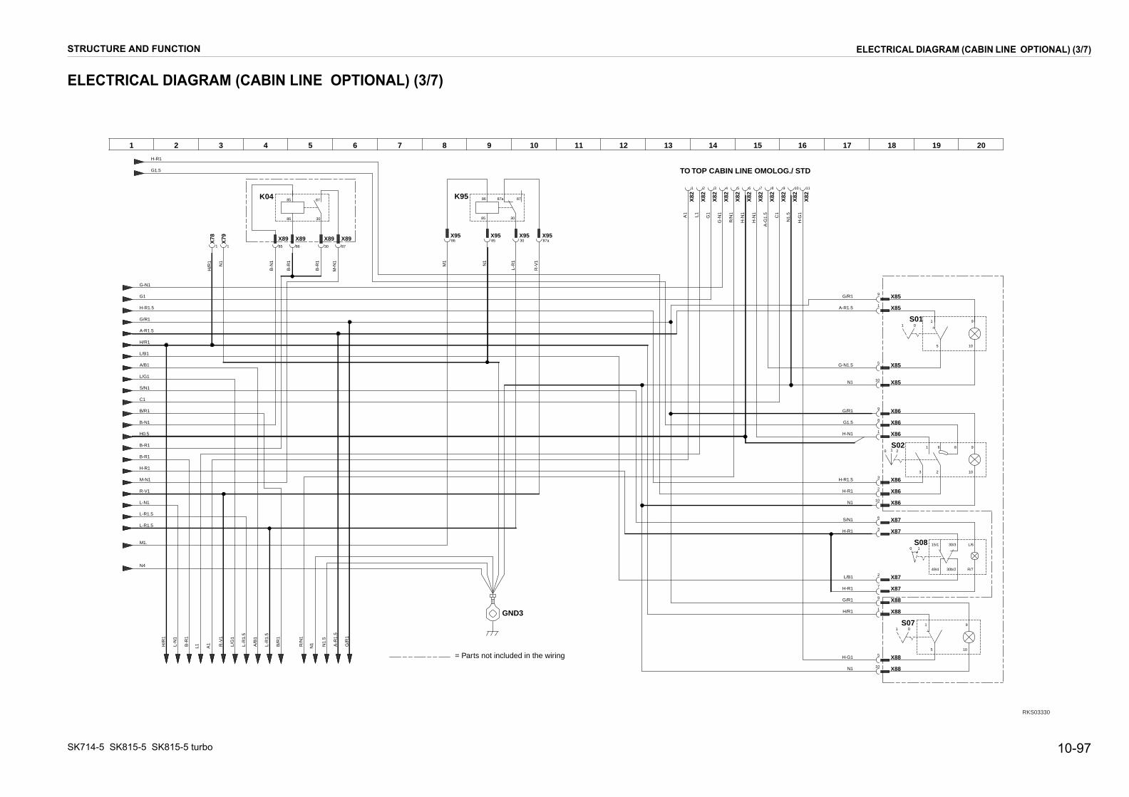
10-97
S02 1 6 8 9
3 2 10
S07 1 9
5 10
S01 1 9
5 10
S08 15/1 30/3 L/6
49/4 30b/2 R/7
X85
X85
X85
X85
X86
X86
X86
X86
X86
X86
X87
X87
X87
X87
X88
X88
X88
X88
10
9
1
5
9
8
1
3
2
10
6
3
2
7
9
1
5
10
X82
X82
X82
X82
X82
X82
X82
6 7 8 9 10 11
15 16 17 18 19 20
G/R1
G/R1
G1.5
G-N1.5
H/R1
H-G1
A-R1.5
H-R1.5
N1
N1
G/R1
N1
H-N1
L/B1
S/N1
H-R1
H-R1
H-R1
H-N
1
H-N
1
C1
N1.
5
A-G
1.5
H-G
1
0 21
1 0
1 0
10
INE OMOLOG./ STD
RKS03330
ELECTRICAL DIAGRAM (CABIN LINE OPTIONAL) (3/7)
SK714-5 S
ELECTR
STRUCTUR
K815-5 SK815-5 turbo
ICAL DIAGRAM (CABIN LINE OPTIONAL) (3/7)
N1
A1
L1 L/G
1
L-R
1.5
A/B
1
L-R
1.5
B/R
1
R/N
1
N1.
5
G/R
1
A-R
1.5
R-V
1
L-N
1
B-R
1
H/R
1
X82
X82
X82
X82
1 2 3 4 5
K04 85 87
86 30
G1.5
H-R1
B-R
1
X8986
X8930
X8987
M-N
1
B-N
1
X8985
B-R
1
X78
1
X79
1
1 2 3 4 5 6 7 8 9 10 1211 13 14
A1 L1 G1
G-N
1
R/N
1
GND3
H/R
1
N1
G1
H-R1.5
A-R1.5
L/B1
A/B1
L/G1
B-R1
B-R1
H-R1
M-N1
R-V1
G/R1
N4
G-N1
H/R1
C1
B/R1
L-N1
S/N1
B-N1
H0.5
L-R1.5
L-R1.5
M1.
K95 86 87a 87
85 30
X9586
X9585
X9530
X9587a
N1
L-R
1
R-V
1
M1
TO TOP CABIN L
= Parts not included in the wiring
E AND FUNCTION

SK714-
C
S03 1 2
54
S05
1 7 9
3 10
S06 1 7 9
3 10
S09 2 8 5 10
4 6 3 1 7
16 17 18 19 20
X104
X104
X104
X105
X105
X105
X105
X105
X105
X106
X106
X106
X106
X106
X107
X107
X107
X107
X107
X105
X105
2
1
54
10
8
2
4
3
1
9
7
1
3
10
9
7
1
3
10
7
5
N1
N1
A1
A1
H/R1
G/R1
L/R1
A/N1
L1
G/R1
V-B1
V1
L-R1.5
G/R1
L-R1.5
C-B1
C1
L1
A/N1
N1
G/R1
0 21
0 21
0 21
1 0
RKS3340
STRUCTURE AND FUNCTION ELECTRICAL DIAGRAM (CABIN LINE OPTIONAL) (4/7)
5 SK815-5
TRICA
X49.1
X49.1
X49.1
X49.1
X49.1
X49.1
X49.1
X49.1
X49.1
X49.1
X49.1
1
2
3
4
5
6
7
8
9
1
1
1
L-N
1
B-R
1
H/R
1
FR
OM
FR
AM
E L
INE
OP
T
10-98 SK815-5 turbo
L DIAGRAM (CABIN LINE OPTIONAL) (4/7)
S13 S14 S36 S37 S15 S38 S39 S40HL1 HL2 HL3 HL4
0
1
HL5
X83
X83
X83
X83
X83
X83
X83
X84
X84
X84
X84
X84
X84
X84
X84
X84
X84
1 2 3 4 5 6 11 1 2 3 4 5 6 7 8 9 11
C/B
1
L/N
1
Z-N
1
A-G
1
A-N
1
N1
N1
B-R
1
B/R
1
A/B
1
B-R
1
V/B
1
L/G
1
A/V
1
Z/N
1
A-B
1
V/B
0.8
L/G
0.8
A/V
0.8
Z/N
0.8
A-B
0.5
R-N
0.8
N0.
8
R-N
0.8
V/B
0.8
L/G
0.8
A/V
0.8
Z/N
0.8
A-B
0.5
A-G
0.5
A-N
0.5
Z-N
0.5
N0.
8
2 3 4 5 6 7 8 9 10 1211 13 14 15
X90
X90
X90
X90
X90
X90
X90
X90
X90
X90
X90
X90
X90
X90
X90
X90
X90
X90
X90
X90
X90
1 2 3 4 5 6 7 8 9 10 11 12 13 14 15 16 17 18 19 20 21
L/G
1
L-R
1.5
A/B
1
L-R
1.5
B/R
1
R/N
1
N1
G/R
1
A-R
1.5
R-V
1
A1L1
N1.
5
X91
5
X91
1
X91
9
X91
10
N1
S-N
1
G/R
1
L-R
1.5
A-V
1
C/B
1
L-R
1.5
A/N
1
L-N
1
A/V
1
R/N
1
R-V
1
L/N
1
Z-N
1
N1.
5
A-N
1
V/B
1
L/R
1
A-G
1
Z/N
1
A-B
1
A-R
1.5
K05
Z-N1
A-B1
A-G1
A-N1
V1
C1
C-B1
V-B1
A-V1
S-N1
L-R1.5
RIGHT LEVER
LE
FT
LE
VE
RRELAYS UNIT
SWITCH EV ENPI
ELE

10-99
15 16 17 18 19 20
RKS03350
ELECTRICAL DIAGRAM (CABIN LINE OPTIONAL) (5/7)
SK714-5 S
ELECTR
STRUCTUR
K815-5 SK815-5 turbo
ICAL DIAGRAM (CABIN LINE OPTIONAL) (5/7)
1 2 3 4 5 6 7 8 9 10 1211 13 14
K10
53M
31 T 15 53S
K12 86 87a 87
85 30
K11 86 87
85 30
K13
R
+
CL(T)
-(53S)X
90.1
X90
.1
X90
.1
X90
.1
X90
.1
X90
.1
X90
.1
X90
.1
X90
.1
X90
.1
X90
.1
X90
.1
X90
.1
X90
.1
X90
.1
X90
.1
X90
.1
X90
.1
X90
.1
X90
.1
X90
.1
1 2 3 4 5 6 7 8 9 10 11 12 13 14 15 16 17 18 19 20 21
K08 85 30
86 87
K09 85 30
86 87
K07 85 30
86 87
RELAYS UNIT
K05
E AND FUNCTION

SK714-
C
16 17 18 19 20
X81
-2
X81
-3
X81
-4
L6 L7
L1
X80
-15
X80
-16
X81
-7
X81
-5
X81
-6
X81
-8
X81
-1
L9L8 L10DL2DL1 DL3
L2 L3 L4
X80
-12
X80
-14
X80
-11
L5
RKS03360
STRUCTURE AND FUNCTION ELECTRICAL DIAGRAM (CABIN LINE OPTIONAL) (6/7)
5 SK815-5
TRICA
1
L6
L7
+50
POS.
DL3
L8
+15
GND
GND
C2
C3
POS.
10-100 SK815-5 turbo
L DIAGRAM (CABIN LINE OPTIONAL) (6/7)
2 3 4 5 6 7 8 9 10 1211 13 14 15
CONTROL PANEL (EXTERNAL WIEW)
DL2L6
C1
L8L7 L9 L10
C
H
L1 L3L2 L4 L5 C2
DL1 DL3
E
F
C3
PARKING BRAKE LAMP
SECOND SPEED LAMPX81-4
X81-3
M-B1
M-V1NEGATIVE
POSITIVE
DL1
DL2
WARNING LED
SEAT LED
X81-7
X81-8 G/N1
M/B1NEGATIVE
NEGATIVE
X80-11
X80-10
X80-12
X80-14
X80-13
X80-15
X80-16
B1 L2+50X80-4 START SIGNAL
FUNCTION
SAFETY BAR OPEN LED
FLOAT LAMP
PIN
X81-1
X81-2
POWER SUPPLY (+12V)X80-8
X80-7
X80-6
X80-5
GROUND
GROUND
M-N1
B/N1
WIRE COLOURSIGNAL
NEGATIVE
POSITIVE
POS.
L9
L10
H-R1+15
GND
GND
L1
L3
N1 L4
FUNCTION
FUEL LEVEL INDICATOR
WATER TEMPERAT. INDICATOR
X80-2
X80-3
PIN
X80-1
C-N1
B-N1
WIRE COLOUR
ohm
ohm
SIGNAL
L5
POS.
M1POSITIVEPREHEATING LAMP
LOW BEAM LAMP
FUNCTION
DIRECTION LAMP
PIN
X81-5
X81-6
AIR FILTER LAMP
GENERATOR LAMP
ENGINE OIL PRESSURE LAMP
H0.5
L-N1
WIRE COLOURSIGNAL
POSITIVE
POSITIVE
B-G1
S1
C-L1
NEGATIVE
NEGATIVE
NEGATIVE
INTERNAL LIGHTS (+ LUCI)
HYDRAULIC OIL FILTER LAMP
FUNCTION
BUZZER
PIN
X80-9
S-G1
Z-B1
G-N1
WIRE COLOUR
NEGATIVE
NEGATIVE
SIGNAL
POSITIVE
P1
h0000000 C2
X80-2X80-9
HOUR COUNTER
-X80-6
C1
X80-3
C3
FUELLEVEL
INTERNAL CONNECTION CONTROL PANEL
+X80-8
WATER TEMP.INDICATOR
ELE
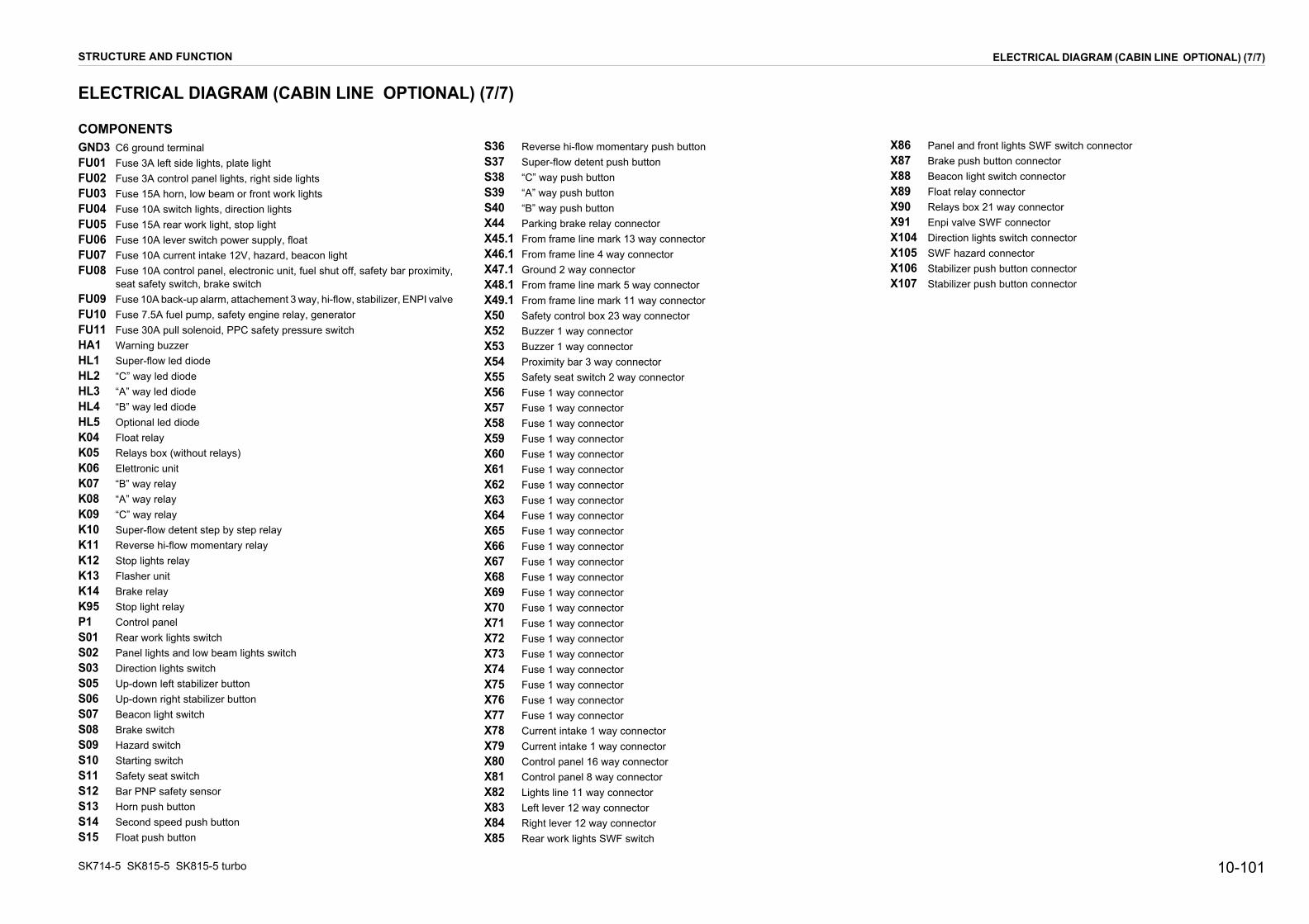
10-101
X86 Panel and front lights SWF switch connectorX87 Brake push button connectorX88 Beacon light switch connectorX89 Float relay connectorX90 Relays box 21 way connectorX91 Enpi valve SWF connectorX104 Direction lights switch connectorX105 SWF hazard connectorX106 Stabilizer push button connectorX107 Stabilizer push button connector
ELECTRICAL DIAGRAM (CABIN LINE OPTIONAL) (7/7)
SK714-5 S
ELECTR
COMPONGND3 C6 gFU01 FuseFU02 FuseFU03 FuseFU04 FuseFU05 FuseFU06 FuseFU07 FuseFU08 Fuse
seatFU09 FuseFU10 FuseFU11 FuseHA1 WarHL1 SupeHL2 “C” wHL3 “A” wHL4 “B” wHL5 OptiK04 FloaK05 RelaK06 ElettK07 “B” wK08 “A” wK09 “C” wK10 SupeK11 ReveK12 StopK13 FlasK14 BrakK95 StopP1 ConS01 ReaS02 PaneS03 DireS05 Up-dS06 Up-dS07 BeacS08 BrakS09 HazaS10 StarS11 SafeS12 Bar S13 HornS14 SecoS15 Floa
STRUCTUR
K815-5 SK815-5 turbo
ICAL DIAGRAM (CABIN LINE OPTIONAL) (7/7)
ENTSround terminal 3A left side lights, plate light 3A control panel lights, right side lights 15A horn, low beam or front work lights 10A switch lights, direction lights 15A rear work light, stop light 10A lever switch power supply, float 10A current intake 12V, hazard, beacon light 10A control panel, electronic unit, fuel shut off, safety bar proximity,
safety switch, brake switch 10A back-up alarm, attachement 3 way, hi-flow, stabilizer, ENPI valve 7.5A fuel pump, safety engine relay, generator 30A pull solenoid, PPC safety pressure switch
ning buzzerr-flow led diodeay led diodeay led diodeay led diode
onal led diodet relayys box (without relays)ronic unitay relayay relayay relayr-flow detent step by step relayrse hi-flow momentary relay
lights relayher unite relay light relaytrol panelr work lights switchl lights and low beam lights switch
ction lights switchown left stabilizer buttonown right stabilizer buttonon light switche switchrd switch
ting switchty seat switchPNP safety sensor push buttonnd speed push button
t push button
S36 Reverse hi-flow momentary push buttonS37 Super-flow detent push buttonS38 “C” way push buttonS39 “A” way push buttonS40 “B” way push buttonX44 Parking brake relay connectorX45.1 From frame line mark 13 way connectorX46.1 From frame line 4 way connectorX47.1 Ground 2 way connectorX48.1 From frame line mark 5 way connectorX49.1 From frame line mark 11 way connectorX50 Safety control box 23 way connectorX52 Buzzer 1 way connectorX53 Buzzer 1 way connectorX54 Proximity bar 3 way connectorX55 Safety seat switch 2 way connectorX56 Fuse 1 way connectorX57 Fuse 1 way connectorX58 Fuse 1 way connectorX59 Fuse 1 way connectorX60 Fuse 1 way connectorX61 Fuse 1 way connectorX62 Fuse 1 way connectorX63 Fuse 1 way connectorX64 Fuse 1 way connectorX65 Fuse 1 way connectorX66 Fuse 1 way connectorX67 Fuse 1 way connectorX68 Fuse 1 way connectorX69 Fuse 1 way connectorX70 Fuse 1 way connectorX71 Fuse 1 way connectorX72 Fuse 1 way connectorX73 Fuse 1 way connectorX74 Fuse 1 way connectorX75 Fuse 1 way connectorX76 Fuse 1 way connectorX77 Fuse 1 way connectorX78 Current intake 1 way connectorX79 Current intake 1 way connectorX80 Control panel 16 way connectorX81 Control panel 8 way connectorX82 Lights line 11 way connectorX83 Left lever 12 way connectorX84 Right lever 12 way connectorX85 Rear work lights SWF switch
E AND FUNCTION

PAGE INTENTIONALLYLEFT BLANK
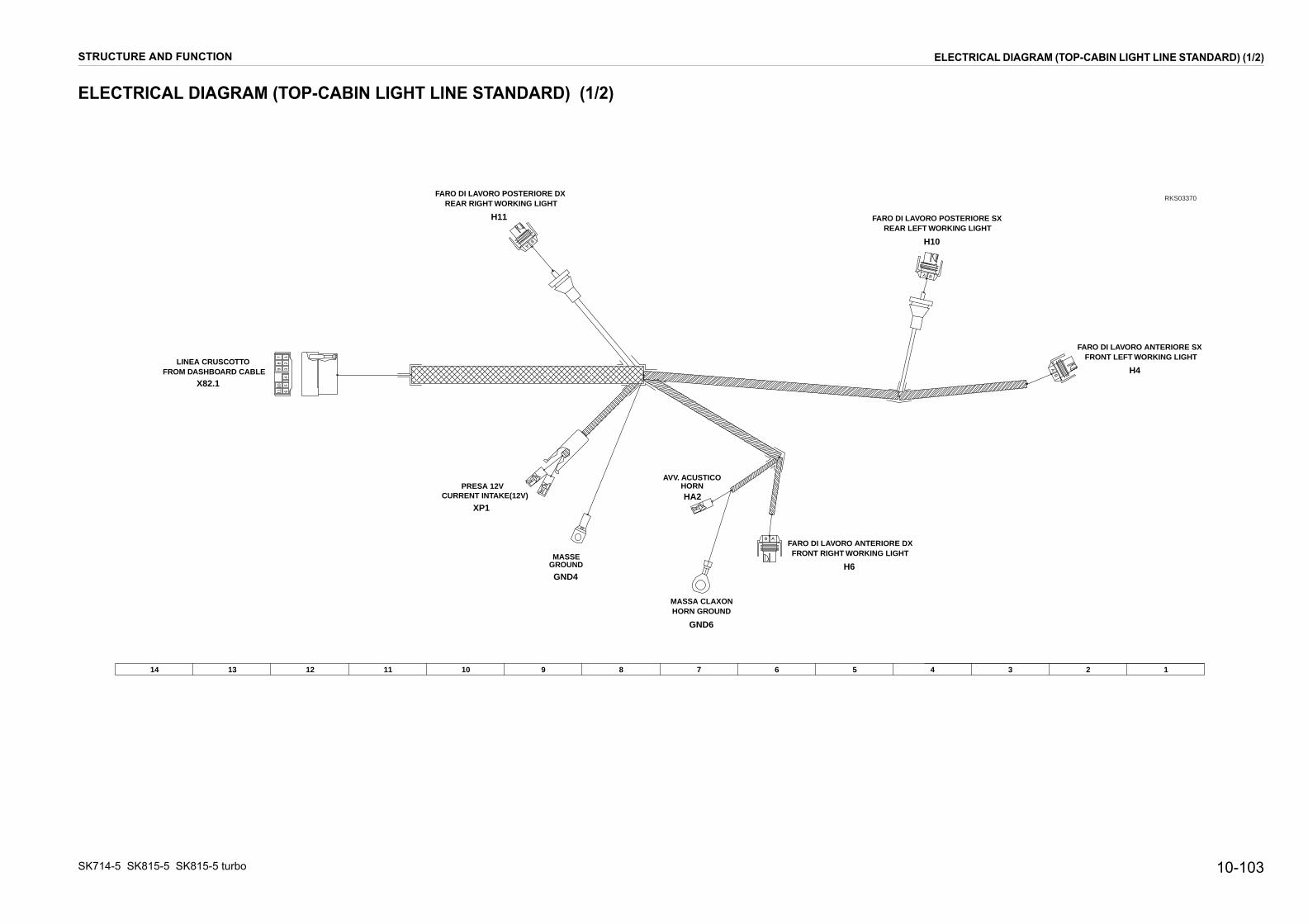
10-103
4 3 2 1
NTERIORE DXRKING LIGHT
FARO DI LAVORO POSTERIORE SXREAR LEFT WORKING LIGHT
FARO DI LAVORO ANTERIORE SXFRONT LEFT WORKING LIGHT
H10
H4
A B
AB
RKS03370
ELECTRICAL DIAGRAM (TOP-CABIN LIGHT LINE STANDARD) (1/2)
SK714-5 S
ELECTR
STRUCTUR
K815-5 SK815-5 turbo
ICAL DIAGRAM (TOP-CABIN LIGHT LINE STANDARD) (1/2)
14 13 12 11 10 9 8 7 6 5
7 16
54
32
98
1110
AB
CURRENT INTAKE(12V)PRESA 12V
FARO DI LAVORO A
HORNAVV. ACUSTICO
FRONT RIGHT WO
LINEA CRUSCOTTOFROM DASHBOARD CABLE
FARO DI LAVORO POSTERIORE DXREAR RIGHT WORKING LIGHT
GROUNDMASSE
MASSA CLAXONHORN GROUND
X82.1
HA2
H6
H11
GND4
XP1
GND6
AB
E AND FUNCTION

SK714-
ELEC
HA
FR
OM
CA
BIN
LIN
E
STRUCTURE AND FUNCTION ELECTRICAL DIAGRAM (TOP-CABIN LIGHT LINE STANDARD) (2/2)
alrminal
pmptht
1 way connectoray connector
way connectorts 2 way connectorhts 2 way connectorctor
on light 1 way connectoron light 1 way connector
5 SK815-5
TRICA
1
2
X82.1
X82.1
X82.1
X82.1
X82.1
X82.1
X82.1
X82.1
X82.1
X82.1
X82.1
1
2
3
4
5
6
7
8
9
10
11
X113
1
10-104 SK815-5 turbo
L DIAGRAM (TOP-CABIN LIGHT LINE STANDARD) (2/2)
2 3 4 5 6 7 8 9 10
H1
C1
H4 H6 H10 H11
H-G1
A-G1
H-N1
H-N1
N1.5
A-G
1
N1
H-G
1
N1
N1
H-N
1
H-N
1
A-G
1
N1
N1
X108 X108 X109 X109 X110 X110 X111 X111 XP1AXP1
1 2 1 2 A B A B 12
GND4
GND6
M
= Parts not included in the wiring
RKS03390
COMPONENTSGND4 C6 ground terminGND6 C8 horn ground teH1 Beacon lightH4 Left front work lamH6 Right front work laH10 Left rear work lighH11 Right rear work ligHA2 HornX82.1 From cabin line 1X10⁸ Left front light 2 wX109 Right front light 2X110 Left rear work lighX111 Right rear work ligX113 Horn 1 way conneXP1 12V socket, beacXP1A 12V socket, beac

10-105
5 4 3 2 1
RKS03540
AB
ANTERIORE DXRIGHT LIGHT
ORE SXGHT
REAR LEFT LIGHTFANALE POSTERIORE SX
FANALE ANTERIORE SXFRONT LEFT LIGHT
FARO ANABBAGLIANTE SXFRONT LEFT MAIN BEAM
H7
H8
H5
H4
ELECTRICAL DIAGRAM (TOP-CABIN LIGHT LINE OMOLOGATION) (1/2)
SK714-5 S
ELECTR
STRUCTUR
K815-5 SK815-5 turbo
ICAL DIAGRAM (TOP-CABIN LIGHT LINE OMOLOGATION) (1/2)
16 15 14 13 12 11 10 9 8 7 6
7 16
54
32
98
1110
AB
A B
A
B
CURRENT INTAKE(12V)PRESA 12V
FANALINOFARO ANABBAGLIANTE DX
HORNAVV. ACUSTICO
FRONT RIGHT MAIN BEAMFRONT
LINEA CRUSCOTTOFROM DASHBOARD CABLE
REAR RIGHT LIGHTFANALE POSTERIORE DX
FARO DI LAVORO POSTERIORE DXREAR RIGHT WORKING LIGHT
LUCE TARGANUMBER PLATE LIGHT
FARO DI LAVORO POSTERIREAR LEFT WORKING LI
GROUNDMASSE
HORN GROUNDMASSA CLAXON
X82.1
HA2
H6
H9
H11
H12
H10
GND4
XP1
GND6
ł6
ł6
ł8
E AND FUNCTION
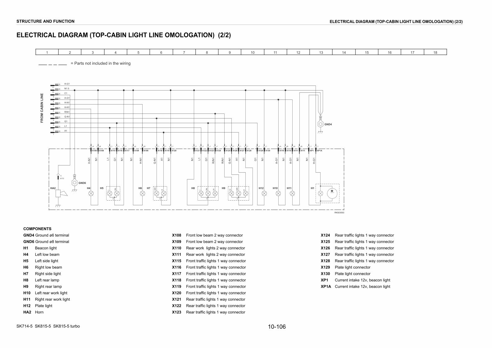
SK714-
C
14 15 16 17 18
GND4
RKS03550
M
COGNGNH1H4H5H6H7H8H9H10H11H12HA
124 Rear traffic lights 1 way connector125 Rear traffic lights 1 way connector126 Rear traffic lights 1 way connector127 Rear traffic lights 1 way connector128 Rear traffic lights 1 way connector129 Plate light connector130 Plate light connectorP1 Current intake 12v, beacon lightP1A Current intake 12v, beacon light
STRUCTURE AND FUNCTION ELECTRICAL DIAGRAM (TOP-CABIN LIGHT LINE OMOLOGATION) (2/2)
5 SK815-5
TRICA
1
H
FRO
M C
AB
IN L
INE
MPONENTSD4 Ground øD6 Ground ø
Beacon liLeft low bLeft side Right lowRight sideLeft rear Right reaLeft rear Right reaPlate ligh
2 Horn
10-106 SK815-5 turbo
L DIAGRAM (TOP-CABIN LIGHT LINE OMOLOGATION) (2/2)
2 3 4 5 6 7 8 9 10 1211 13
H1A2
H-N1
C1
N1.5
H8
L 58L
54
31
H9
54 58R
R
31
H4 H5
L 58L
31
H6 H7
58R
R31
H10 H11
L1
G1
R/N1
N1
H-G
1
A1
G-N
1
A1
G-N1
H-G1
R/N
1
G1L1N1
A1
G-N
1
G1L1 N1
N1
N1
N1
H12
X121 X122 X123 X124 X126 X127X108 X108 X109 X109X115 X116 X117 X118 X119 X120 X111 X111 XP1 XP1AX125 X128 X129 X130 X110 X110
1 1 1 1 1 1A B A B1 1 1 1 1 1 A B 1 11 1 1 1 A B
G1
R/N
1
N1
N1
N1
N1
H-N
1
H-N1
H-N
1
A-G1
A-G
1
A-G
1
X1131
GND6
X82.11
X82.12
X82.13
X82.14
X82.15
X82.16
X82.17
X82.18
X82.19
X82.110
X82.111
= Parts not included in the wiring
6 terminal8 terminalghteamlight beam light
lampr lampwork lightr work lightt
X108 Front low beam 2 way connectorX109 Front low beam 2 way connectorX110 Rear work lights 2 way connectorX111 Rear work lights 2 way connectorX115 Front traffic lights 1 way connectorX116 Front traffic lights 1 way connectorX117 Front traffic lights 1 way connectorX118 Front traffic lights 1 way connectorX119 Front traffic lights 1 way connectorX120 Front traffic lights 1 way connectorX121 Rear traffic lights 1 way connectorX122 Rear traffic lights 1 way connectorX123 Rear traffic lights 1 way connector
XXXXXXXXX
ELE

STRUCTURE AND FUNCTION ELECTRICAL DIAGRAM (STANDARD)
ELECTRICAL DIAGRAM (STANDARD)
L6 L7 L8 L9 L10
C1
L1
C
L2 L3
H
L4 L5
DL2 DL3DL1
E
C2 C3
F
S13 S14
NC
NO
C
NC
NO
C
WIRE COLOUR
WIRE COLOUR
POWER SUPPLY (+12V)
FLOAT LAMP
SAFETY BAR OPEN LED
FUNCTION
SECOND SPEED LAMP
L8 X81-2
X81-3
X81-4L7
L6 PARKING BRAKE LAMP
X80-7
X80-8
PIN
X81-1DL3
POS.
+15
POSITIVE
POSITIVE
NEGATIVE
SIGNAL
NEGATIVE
+15
WATER TEMPERAT. INDICATOR
FUEL LEVEL INDICATOR
START SIGNAL
FUNCTION
X80-2
X80-5
X80-6
X80-4
X80-3
X80-1
GND
GND
+50
C2
C3
GROUND
GROUND
PINPOS.
ohm
ohm
GND
GND
+50
SIGNAL
DIRECTION LAMP
ENGINE OIL PRESSURE LAMP
FUNCTION
X81-6L10 LOW BEAM LAMP
SEAT LED
WARNING LED
DL2
DL1
X81-8
X81-7
GENERATOR LAMP
L9
POS.
X81-5
PIN
L3
L1
X80-16
X80-15
POSITIVE
NEGATIVE
NEGATIVE
POSITIVE
SIGNAL
NEGATIVE
NEGATIVE
WIRE COLOUR
FUNCTION
HYDRAULIC OIL FILTER LAMP
BUZZER
AIR FILTER LAMP
INTERNAL LIGHTS (+ LUCI)
PREHEATING LAMP
L4
L2
X80-13
X80-14
X80-12
L5
X80-10
X80-11
X80-9
POS. PIN
NEGATIVE
POSITIVE
NEGATIVE
NEGATIVE
POSITIVE
SIGNAL WIRE COLOUR
1 2 3 4 5 6 7 8 9 10
X82.
1
X82.
1
X82.
1
X82.
1
X82.
1
X82.
1
X82.
1
X82.
1
X82.
1
X82.
1
X82.
1
11
H-N
1
H-N
1
C1
N1.
5
H-G
1
X80-2X80-9 X80-3
WATER TEMP.INDICATOR
-X80-6
HOUR COUNTERC1 C3
FUELLEVEL
C2
+X80-8
X80-
15
X80-
16
X80-
12
X80-
14
X80-
11X8
1-7
X81-
2
X81-
3
X81-
4
L6 L7
X81-
5
X81-
6
L9L8 L10
L1 L3L2 L4
X81-
8
X81-
1
DL2DL1 DL3
L5
B-N1
C-N1
B1
N1
H-R1
G-N1
Z-B1
S-G1
M1
C-L1
S1
B-G1
B/N1
M-N1
M-V1
M-B1
L-N1
H0.5
M/B1
G/N1
GND2
L-R1.5
l
N4
R-N2.5
R4
R-N1.5
M-V
1
X37
M1
M-B
1
X36X36X35X3512121
N1
N1N
1
N1
M-N
1
V-N
1
R2.
5
L-G
1
X34X34X33X33X32 X32A
21211 1
R-G1
B-G1
M2.5
R2.5
R-V1
B1
S1
C-N1
C-L1
S-G1
B-N1
pS32
pS33
Y6 Y3Y2Y1
= Parts not included in the wiring
B-G1
H-L1
H-L1
M1
H-L1
X4485
X4430
X4487a
X4486 K14 86 87a 87
85 30
BRAKE P.B. IN
HI-SPEED P. B. IN
FLOAT P. B. IN
SAF. BAR. SW IN
SEAT SWITCH IN
POW. SUPP. +12V
EV BRAKE OUT
STOP ENGINE OUT
BRAKE LIGHT OUT
SAF. BAR.LED OUT
SEAT LED OUT
WARNING LED OUT
FLOAT OUT
BUZZER OUT (-)
HI-SPEED OUT
GND
HORN OUT
START SIGN. IN
+12V HORN
HORN PUSH B. IN
PPC SAF. SW. IN
EV PPC OUT
BUZZER OUT (+)
10A
B-R
1
H-R1
H-R1.5
B/R1
V-N1
L-G1
B1
C1
B-N1
S/N1
L/B1
L/G1
G/N
1
G/N1
Z-B
1
Z-B1
X50
X50
X50
X50
X50
X50
X50
X50
X50
X50
X50
X50
X50
X50
X50
X50
X50
X50
X50
X50
X50
X50
X50
23
22
21
20
19
18
17
16
15
14
13
12
11
10
9
8
7
6
5
4
3
2
1
H0.
5
Z-B
1
H-R
2.5
M-N
1
X81
8
X81
7
X81
6
X81
5
X81
4
X81
3
X81
2
X81
1
X80
16
X80
15
X80
14
X80
13
X80
12
X80
11
X80
10
X80
9
X80
8
X80
7
X80
6
X80
5
X80
4
X80
3
X80
2
X80
1
K06
P1
M-V
1
G/N
1
R/N1
G/R
1
A-R
1.5
H/R
1
R-N
2.5
R-G
1
M/B
1
B-G
1
M-B
1
B/N
1
L-R
1.5
H-R
1
H-R
1
C-B
1
H-R
1
N1
C/N
1
X77X75X73X71X69X67X65X63X61X59X5711111111111
X76X74X72X70X68X66X64X62X60X58X5611111111111
X552
X551
X54C
X54B
X54A
X531
X521
S1
C-L
1
M1
S-G
1
G/N
1
H-R
1
B1
B-N
1
N1
C-N
1
R2.
5R-N2.5A/B1
M/B1
HA1
R/N1
C/N1
C-B1
B/N1
R4
N1.5
R-N1.5
M-B1
CONTROL PANEL (UNIDECK)
B1
ELEC
TRO
NIC
UN
IT
M2.
5
H-R
2.5
S12S11
H-R
2.5
H-R
2.5
H-R
2.5
H-R
2.5
H-R
2.5
H-R
2.5
3A15A7.5A15A10A10A7.5A7.5A30AR1
STOFF ACC
S10
R1 ACC BR R2 C
B
B-R
1R
-N0.
5
GND3
B-R
1
B-R
1
X89
85
B-N
1
X82
X82
X82
X82
X82
X82
X82
X82
X82
X82
X82
1110987654321
A-G
1.5
RIG
HT
LEVE
R
R-N
0.5
L/G
0.5
L/G
1
X84X84
S15
M-N
1
L/G
0.5
V/B
0.5
= Parts not included in the wiring
LEFT
LEV
ER
X89
87
X89
30
X89
86
10
S08
15/1 30/3 L/6
49/4 30b/2 R/7
N1.
5
H-G
1
H-N
1
H-N
1
X88
X88
X88
X88
X87
X87
X87
X87
X86
X86
X86
X86
X86
X86
X85
X85
X85
X85
B/R
1
A/B
1
X83X83X83
C1
H-R1.5
H-R1
H-R1
S/N1
N1
G/R1
L/B1
N1
N1
H-R1
A-R1.5
H/R1
H-G1
H-N1
A-G1.5
G1.5
G/R1
G/R1
B-R
1
1 0
S01
1 9
5 10
1 0
S07
1 9
5 10
S14S13
0 21
3
10
5
1
9
7
2
3
6
10
2
1
8
9
10
5
1
9
S02
1 6 8 9
3 2 10
K04 85 87
86 30
*AMP
1CONNETTORE RELE’ BRAKE / BRAKE RELAY CONN.X44
104610027 (KUE 37A-54-14291)UNIDECKPANNELLO STRUMENTI /CONTROL PANELP1
1CONNETTORE 23 VIE CENTRALINA ELETTRONICA / ELECTRONIC UNIT 23 WAY CONN.X50
106AA008 (KUE 885081160)CIAM
106AA008 (KUE 885081160)CIAM
157061 (KUE 885071043)CIAM
106AA018 (KUE 885081159 )CIAM
0A003455 (KUE 37A-06-11410)CIAM
E-A1TMU/3AP (KUE 37A-06-11250)SAIET
01171077 (KUE 885070046)
1PULSANTE FLOAT / FLOAT PUSH BUTTONS15
*
FUSE 15A REAR WORK LIGHT
FUSE 30A PULL SOLENOID, PPC SAFETY PRESSURE SWITCHFUSE 7.5A FUEL PUMP, SAFETY ENGINE RELAY, GENERATOR
FUSE 10A CURRENT INTAKE 12V, BEACON LIGHT
FUSE 7.5A SWITCH LIGHTSFUSE 15A HORN, FRONT WORK LIGHTSFUSE 3A CONTROL PANEL LIGHTS
FUSE 7.5A BACK-UP ALARMFUSE 10A CONTROL PANEL, ELECTRONIC UNIT, FUEL SHUT OFF, SAFETY BAR PROXIMITY, SEAT SAFETY SWITCH, BRAKE SWITCH
CIAMCIAM
1RELE’ FRENO / BRAKE RELAY K141CENTRALINA ELETTRONICA / ELECTRONIC UNIT K06
1*AMPCONNETTORE 1 VIA BUZZER /BUZZER 1 WAY CONN.X531*AMPCONNETTORE 1 VIA BUZZER /BUZZER 1 WAY CONN.X52
1*AMPCONNETTORE MARK 5 VIE DA LINEA TELAIO / FROM FRAME LINE 5 WAY CONN.X48.11DTP04-2PDEUTSCHCONNETTORE 2 VIA MASSA DA LINEA TELAIO / FROM FRAME LINE 2 WAY GROUND CONN.X47.11DTP04-4PDEUTSCHCONNETTORE 4 VIE DA LINEA TELAIO / FROM FRAME LINE 4 WAY CONN.X46.11*AMPCONNETTORE MARK 13 VIE DA LINEA TELAIO / FROM FRAME LINE 13 WAY CONN.X45.1
1PULSANTE SECONDA VELOCITA’ /SECOND SPEED PUSH BUTTONS141PULSANTE CLAXON /HORN PUSH BUTTONS131PROXIMITY DI SICUREZZA PNP BRACCIOLO /BAR PNP SAFETY SENSORS121FINECORSA SICUREZZA SEDILE /SAFETY SEAT SWITCHS111QUADRO AVVIAMENTO /STARTING SWITCHS101PULSANTE FRENO / BRAKE SWITCHS081INTERRUTTORE SWF LAMPADA ROTANTE /BEACON LIGHT SWITCHS071INTERRUTTORE SWF 2 POSIZIONI STABILI LUCI STRUMENTO E ANAB. /PANEL LIGHTS AND LOW BEAM LIGHTS SWITCHS021INTERRUTTORE SWF 1 POS. STABILE FARI LAVORO POST /REAR WORK LIGHTS SWITCHS01
1RELE’ FLOAT / FLOAT RELAYK04
11BUZZER SEGNALAZIONE ANOMALIE / WARNING BUZZERHA11111FU111FU101FU091FU081FU07
FU061FU051FU041FU031FU02
FU01
QTATIPO/ TYPECOSTRUT./ SUPP.DESCRIZIONE/ DESCRIPTIONNOME/ NAME
1*AMPOCCHIELLO C6 MASSA / C6 GROUND TERMINALGND3
****
DT04-12P,DT06-12-S*
SWF
CONNETTORE 1 VIA FUSIBILE /FUSE 1 WAY CONN.CONNETTORE 1 VIA FUSIBILE /FUSE 1 WAY CONN.CONNETTORE 1 VIA FUSIBILE /FUSE 1 WAY CONN.CONNETTORE 1 VIA FUSIBILE /FUSE 1 WAY CONN.CONNETTORE 1 VIA FUSIBILE /FUSE 1 WAY CONN.CONNETTORE 1 VIA FUSIBILE /FUSE 1 WAY CONN.CONNETTORE 1 VIA FUSIBILE /FUSE 1 WAY CONN.CONNETTORE 1 VIA FUSIBILE /FUSE 1 WAY CONN.CONNETTORE 1 VIA FUSIBILE /FUSE 1 WAY CONN.CONNETTORE 1 VIA FUSIBILE /FUSE 1 WAY CONN.CONNETTORE 1 VIA FUSIBILE /FUSE 1 WAY CONN.CONNETTORE 1 VIA FUSIBILE /FUSE 1 WAY CONN.CONNETTORE 1 VIA FUSIBILE /FUSE 1 WAY CONN.CONNETTORE 1 VIA FUSIBILE /FUSE 1 WAY CONN.CONNETTORE 1 VIA FUSIBILE /FUSE 1 WAY CONN.CONNETTORE 1 VIA FUSIBILE /FUSE 1 WAY CONN.CONNETTORE 1 VIA FUSIBILE /FUSE 1 WAY CONN.CONNETTORE 1 VIA FUSIBILE /FUSE 1 WAY CONN.CONNETTORE 1 VIA FUSIBILE /FUSE 1 WAY CONN.
11CONNETTORE RELE’ FLOAT / FLOAT RELAY CONN.X891CONNETTORE SWF INTERRUTTORE LAMPEGGIANTE /BEACON LIGHT SWITCH CONN.X881PNEUTRONCONNETTORE PULSANTE FRENO / BRAKE SWITCH CONN.X871SWFCONNETTORE SWF LUCI STRUM. E FARI ANABB. ANTERIORI /PANEL AND FRONT LIGHTS SWF SWITCH CONN.X861SWFCONNETTORE SWF INTERRUTTORE FARI LAVORO POSTERIORI /REAR WORK LIGHTS SWF SWITCH X85
1DEUTSCHCONNETTORE MARK 12 VIE MANIPOLATORE SX / LEFT LEVER 12 WAY CONN.X831AMPCONNETTORE MARK 11 VIE LINEA FARI /LIGHTS LINE 11 WAY CONN.X821*AMPCONNETTORE 8 VIE PANNELLO DI CONTROLLO /CONTROL PANEL 8 WAY CONN.X811*AMPCONNETTORE 16 VIE PANNELLO DI CONTROLLO / CONTROL PANEL 16 WAY CONN.X801*AMPCONNETTORE 1 VIA PRESA DI CORRENTE /CURRENT INTAKE 1 WAY CONN.X791*AMPCONNETTORE 1 VIA PRESA DI CORRENTE /CURRENT INTAKE 1 WAY CONN.X781*AMPX771*AMPX761*AMPX751*AMPX741*AMPX731*AMPX721*AMPX711*AMPX701*AMPX691*AMPX681*AMPX671*AMPX661*AMPX651*AMPX641*AMPX631*AMPX621*AMPX611*AMPX601*AMPX591*AMPCONNETTORE 1 VIA FUSIBILE /FUSE 1 WAY CONN.X58
QTATIPO/ TYPECOSTRUTT./ SUPP.DESCRIZIONE/ DESCRIPTIONNOME/ NAME
1*AMPCONNETTORE 1 VIA FUSIBILE /FUSE 1 WAY CONN.X571*AMPCONNETTORE 1 VIA FUSIBILE /FUSE 1 WAY CONN.X561*DEUTSCHCONNETTORE 2 VIE SENSORE SICUREZZA SEDILE /SAFETY SEAT SWITCH 3 WAY CONN. X551*DEUTSCHCONNETTORE 3 VIE SENSORE BARRA / PROXIMITY BAR 3 WAY CONN.X54
G1.5
H-R1
H0.
5
X83 X8431321 11 11
N1
N1
H-R
1.5
FU06 FU02FU03FU04FU05FU07FU08FU09FU10FU11 FU013A
G-N
1
G1
G1
FUSE 3A (LEFT SIDE LIGHTS) 1
X78
1
X79
1
N1
H/R
1
h0000000
FUSE 10A LEVER SWITCH POWER SUPPLY, FLOAT
X84 CONNETTORE MARK 12 VIE MANIPOLATORE DX / RIGHT LEVER 12 WAY CONN. DEUTSCH 1
X10.1
X10.1
X10.1
X10.1
X10.1
X10.1
X10.1
X10.1
X10.1
X10.14X10.1
X10.1
X10.1
X01.1
X01.1
X01.1
X02.1
X02.1
X01.1
13
12
11
10
9
8
7
6
5
3
2
1
4
3
2
-
1 R4
M-N1
N4
M-V1
B1
L-G1
M1
R-N2.5
M2.5
R4
R-N1.5
V-N1
M-B1
L-R1.5
R-G1
S1
C-N1
C-L1
S-G1
B-N1
B-G1
N4
R4
N4
L-G1
M-V1
M1
B-N1
R-N2.5
R4
M-B1
M-N1
R-V1
R-N1.5
B1
S1
C-N1
C-L1
S-G1
L-R1.5
R-G1
B-G1
M2.5
V-N1
N4
R4
X48.1
X48.1
X48.1
X48.1
X46.1
X46.1
X46.1
X45.1
X45.1
X45.1
X45.1
X45.1
X45.1
X45.1
X45.1
X45.1
X45.1
X45.1
X45.1
X45.1
X47.1
X47.1
X46.1
4
3
2
1
4
3
2
13
12
11
10
9
8
7
6
5
4
3
2
1
1
2
1
X48
X48
X48
X48
X46
X46
X46
X45
X45
X45
X45
X45
X45
X45
X45
X45
X45
X45
X45
X45
X47
X47
X46
1
2
3
4
4
4
2
13
12
11
10
9
8
7
6
5
4
3
2
1
1
2
1
R2.
5
R-N
2.5
GND5
N2.
5
DT04-12P,DT06-12-S
P1 CONTROL PANEL (UNIDECK)
X08
6
S-G
1
S26
= Parts not included in the wiring
R6
Y0
S1
G230
D+W
31
M130 50
N50
XB
G1
12Vcc
R50
X11
X09
XM
B2.
5
R-G
1
B2.
5
N2.
5N
2
X13
X11
X11
S-N
1
R-N
1.5
X13X13
B2
FG150A
R6
XF2
R6
XF1
X16
M2 R1S25
X14 X14
N1
R-G
1
X16X15
N1
M2.
5
C-L
1
R2 R3X18X17X17
N1
N1
B-N
1
X18
C-N
1
V1
X06
l
B2
R-N
1.5
R-N
2.5
R-N
1.5
M-V
1
L/B
1
X03
86
X03
30
K01 86 87
85 30
X03
85
X03
87
N1
B1
B2.
5
S-N
1
R-G
1
R4
N1
N1
M-V
1
L/B
1
R-N
1.5
R6
XS1
A
K02
X07
2
X06
-
X07
4
X07
3
XS
X07
1
XS1
B
X08
3
X08
1
X08
5
X21
S28S27
L-R
1
X19
X20
R-V
1
L-R
1
X20 X21
S30S29
L-R
1
X221
X22
Z-N
1
X23X23
S31 HA3
X292
X291
Z-N
1
N1
X281
B-N1
R-G1
B-G1
GND5
R-V1
C-L1
S-G1
B1
S1
C-N1
R-N1.5
R2.5
L-R1
R4
N4
M2.5
R-N2.5
X10
X10
X10
X10
X10
X10
X10
X10
X10
X10
X10
X10
X10
X02
X02
X01
X01
X01
X01
4
1
2
3
7
5
6
9
10
8
13
11
12
-
l
2
1
4
3
X109
2
HA2
X1131
GND6
H6H4
X108
2
H-N
1
N1
X108
1
H-N
1
N1
X109
1
XP1A
1
H1H11H10
A-G
1
A-G
1
N1
X110
A
X110
B
N1
X111
A
X111
B
N1
H-G
1
XP1
2
A-G1
H-N1
H-N1
N1.5
C1
H-G1
GND4
A-G
1
R-B
1
G1
R1
N1
RKS03680
INTERNAL CONNECTION CONTROL PANEL
pU
3GM
1
1
2
1
3
31
21 1- + 21 -AC +
2
1
1 2 1 2 21
ENGINE YANMAR PARTS
M pt
POW
ERB
OX
K03
SAFETYRELAY
pp pp
p
OCCHIELLLO C8 MASSA CLAXON/ C8 HORN GROUND TERMIMAL
CONN. 2 VIE FARO LAVORO POST. DX / RIGHT REAR WORK LIGHTS 2 WAY CONN.
OCCHIELLLO C6 MASSA / C6 GROUND TERMIMALCONNETTORE 1 VIA CLAXON / HORN 1 WAY CONN.CONN. 1 VIA PRESA 12V, GIROFARO / 12V SOCKET, BEACON LIGHT 1 WAY CONN.
CONNETTORE 2 VIE LUCE ANTERIORE DX / RIGHT FRONT LIGHT 2 WAY CONN.CONN. 2 VIE FARO LAVORO POST. SX / LEFT REAR WORK LIGHTS 2 WAY CONN.
CONNETTORE 2 VIE LUCE ANTERIORE SX / LEFT FRONT LIGHT 2 WAY CONN.CONNETTORE MARK 11 VIE DA LINEA CABINA / FROM CABIN LINE 11 WAY CONN.AVVISATORE ACUSTICO /HORNFARO DI LAVORO POSTERIORE DX / RIGHT REAR WORK LAMPFARO DI LAVORO POSTERIORE SX / LEFT REAR WORK LAMPFARO DI LAVORO ANT. DX / RIGHT FRONT WORK LAMPFARO DI LAVORO ANT. SX / LEFT FRONT WORK LAMPGIROFARO /BEACON LIGHT
DESCRIZIONE
M
GND6
XP1, XP1AX111
X113GND4
X109X110
X108X82.1HA2H11H10H6H4H1
NOME COSTRUTTORE
AMP
DEUTSCH
AMPAMP
AMP
DEUTSCHPACKARDPACKARDAMP
COBO (KUE)COBO (KUE)
CIAM (KUE)
COBO (KUE)COBO (KUE)CIAM (KUE)
1
*
*
**
*
****
1
11
1
1111
QTA
05-531-000 (885111132)05-531-000 (885111132)05-531-000 (885111132)
110450 (885111118)05-531-000 (885111132)
112001 (885100005)
TIPO
111111
CONNETTORE 2 VIE PRESSOSTATO 2 LUCI STOP / STOP LIGHT PRESSURE 2 SWITCH 2 WAY CONN.CONNETTORE 2 VIE PRESSOSTATO 1 LUCI STOP / STOP LIGHT PRESSURE 1 SWITCH 2 WAY CONN.OCCH. C5 SENSORE INTASA. FILTRO OLIO IDRAULICO / IDRAULIC OIL FILTER BLOCKED SWITCH C5 TERMINALCONNETTORE 2 VIE TRASDUTTORE TEMP. ACQUA /ENGINE WATER TEMPERATURE SENDER 2 WAY CONN.
CONNETTORE 2 VIE SENSORE INTASAMENTO FITRO ARIA / AIR FILTER BLOCKED SWITCH 2 WAY CONN.
CONNETTORE 3 VIE POOL-STOP SOLENOIDE CARBURANTE /FUEL POOL-STOP SOLENOID 3 WAY CONN.
CONNETTORE 4 VIE TIMER PULL SOLENOIDE/PULL SOLENOID TIMER 4 WAY CONN.
CONNETTORE 2 VIE PRESSOSTATO 2 BACK-UP /BACK-UP PRESSURE 2 SWITCH 2 WAY CONN.CONNETTORE 2 VIE PRESSOSTATO 1 BACK-UP / BACK-UP PRESSURE 1 SWITCH 2 WAY CONN.
CONNETTORE 3 VIE SENSORE LIVELLO CARBURANTE /FUEL LEVEL SENDER 3 WAY CONN.
OCCHIELLO C6 RESISTENZA PRERISCALDO / PREHEATING START C6 TERMINALCONNETTORE 2 VIE POMPA GASOLIO / FUEL PUMP 2 WAY CONN.
CONNETTORE 3 VIE ALTERNATORE /GENERATOR 3 WAY CONN.CONNETTORE MARK 13 VIE LINEA TELAIO /FRAME LINE MARK 13 WAY CONN.OCCHIELLO C6 ALTERNATORE / C6 GENERATOR TERMINALCONNETTORE 6 VIE SAFETY RELAY /SAFETY RELAY 6 WAY CONN.
CONNETTORE 2 VIE DIODO ANTIDISTURBO / DIODE 2 WAY CONN.
X20
X22X23
X21
X18X19
X17
X16X15X14X13
X08
X11X10X09
X06X07
TIMER 1 SECONDO PULL SOLENOIDE / FUEL PULL SOLENID VALVE TIMER 1 SECONDSAFETY RELAY
RESISTENZA PRERISCALDO /PREHEATING STARTER
CONNETTORE RELE SOLENOIDE CARBURANTE / FUEL SOLENOID RELAY CONN.CONNETTORE 2 VIE / 2 WAY CONN.CONNETTORE 3 VIE LINEA TELAIO /FRAME LINE 3 WAY CONNECTORELETTROVALVOLA STOP SOLENOIDE CARBURANTE /STOP FUEL SOLENOID VALVE DIODO 1A / DIODE 1APRESSOSTATO MINIMA PRESSIONE OLIO MOTORE /ENGINE OIL MIN. PRESSURE SWITCHPRESSOSTATO BACK-UP /BACK-UP ALARM PRESSURE SWITCHPRESSOSTATO BACK-UP /BACK-UP ALARM PRESSURE SWITCHPRESSOSTATO STOP /STOP LIGHTS PRESSURE SWITCHPRESSOSTATO LUCI STOP /STOP LIGHTS PRESSURE SWITCHPRESSOSTATO INTASAMENTO OLIO IDRAULICO /HYDRAULIC OIL FILTER BLOCKED SWITCHSENSORE INTASAMENTO FILTRO ARIA /AIR FILTER BLOCKED SWITCH TRASDUTTORE DI TEMP. ACQUA MOTORE /ENGINE WATER TEMPERATURE SENDERSENSORE LIVELLO CARBURANTE /FUEL LEVEL SENDER
POMPA GASOLIO / FUEL PUMPMOTORINO AVVIAMENTO / STARTER MOTOR
RELE’ SOLENOIDE CARBURANTE /FUEL SOLENID VALVE RELAYALTERNATORE /GENERATORBATTERIA /BATTERY 100AhFUSIBILE GENERALE 80A /GENERAL FUSE 50A
DESCRIZIONE/DESCRIPTION
M1
Y0
X02X03
X01
S31V1
S30S29S28S27S26S25
R1
R3R2
M2
NOME/NAME
G2
K02K03
K01
FG1G1
1
DT06-2SDEUTSCH
DEUTSCHDEUTSCHDEUTSCH
DT06-2SDT06-2SDT06-2S
DEUTSCH
**
*
AMP**
SUMITOMO
SUMITOMO
**
**
MINITIMER
DT06-3S
**
*
**
6189-0442
6195-0021
**
**
1
11
1
11
1
1111
1
11111
11
1
29-0419-0000 (37A-04-11140)
L5 600 103 085 (37C-06-11110)
123900-77010YANMAR
FMDI (KUE)FMDI (KUE)
YANMAR
YANMAR
**
*
CIAM
FMDI (KUE)
FMDI (KUE)DONALDSON (KUE)YANMAR (KUE)COBO (KUE)YANMARYANMAR
FMDI (KUE)
11717.70 (37A-06-11680)11717.70 (37A-06-11680)
129005-779501A 1N4007
**
*
*
11717.70 (37A-06-11680)11717.70 (37A-06-11680)
129100-77500129612-52100
11716/1 (885261034)X770317 (37A-06-11960)(7861-92-3320)
COSTRUT./SUPPL.
YANMAR (KUE)
MATSUSHITA (KUE)YANMAR (DENSO)FIAMM (KUE)CIAM
129423-77200
119802-77200
CB1aH (885071022)
TIPO/TYPE
163028
1
1
11
1
11111111
1
11
1
1
111
1
11
QTA
CONNETTORE 1 VIA PRESSOSTATO PPC SAFETY / PPC SAFETY PRESSURE SWITCH 1 WAY CONN.
OCCHIELLO C6 MASSA / C6 GROUND TERMINAL OCCHIELLO C8 MASSA / C8 GROUND TERMINAL CONNETTORE 5 VIE LINEA CABINA / CABIN LINE 5 WAY CONN.CONNETTORE 2 VIe MASSA / GROUND 2 WAY CONN.CONNETTORE 4 VIE LINEA CABINA / CABIN LINE 4 WAY CONN.CONNETTORE 13 VIE LINEA CABINA / CABIN LINE 13 WAY CONN.CONNETTORE 1 VIA PRESSOSTATO FRENO /BRAKE PRESSURE SWITCH 1 WAY CONN.CONNETTORE 2 VIE EV. SECONDA VELOCITA’ /SECOND SPEED VALVE 2 WAY CONN.CONNETTORE 2 VIE EV. FRENO /BRAKE VALVE 2 WAY CONN.CONNETTORE 2 VIE EV. FLOAT / FLOAT VALVE 2 WAY CONN.CONNETTORE 2 VIE EV. SERVOCOMANDI (PPC) /PPC VALVE 2 WAY CONN.
CONNETTORE 1 VIA PRESSOSTATO PPC SAFETY / PPC SAFETY PRESSURE SWITCH 1 WAY CONN.CONNETTORE MARK 13 VIE LINEA MOTORE /ENGINE LINE 13 WAY CONN. CONNETTORE 2 VIE LINEA MOTORE /ENGINE LINE 2 WAY CONN.CONNETTORE 4 VIE LINEA MOTORE / ENGINE LINE 4 WAY CONN.ELETTROVALVOLA FRENO /BRAKE VALVEELETTROVALVOLA SECONDA VELOCITA’ /SECOND SPEED VALVEELETTROVALVOLA FLOAT /FLOAT VALVEELETTROVALVOLA SERVOCOMANDI /PPC VALVEPRESSOSTATO FRENO STAZIONAMENTO /BRAKE VALVE PRESSURE SWITCHPRESSOSTATO PPC SAFETY / PPC SAFETY PRESSURE SWITCH
DESCRIZIONE/DESCRIPTION
X35
GND5GND2X48X47
X37
X46X45
X36
X32
X33X34
X32A
X10.1X02.1X01.1Y6
NOME/NAME
Y3Y2
S33Y1
S32
DEUTSCHDEUTSCH
**
***
HYDRAFORCEDEUTSCH
AMP
*
**
AMP
**
DTP06-2SDTP-06-4S
**
***
SUPERSEALSUPERSEAL
DTP04-4P
*
**
**
*
COSTRUT. / SUPPL.FMDI (KUE)FMDI (KUE)HYDRAFORCEHYDRAFORCEHYDRAFORCE
11717.75 (37A-06-11670)
TIPO/ TYPE
****
1
1111
111
1
1
11
1
11111111
QTA1
( WIRE SIDE WIEW WIRING )
WIRE POSITIONINGON CONNECTOR
4 5
1 2
X08
6
3
43
21
X07
X14, X18
+ -
3
X13
1 2
OCCHIELLO C6 MASSA / C6 GROUND TERMINAL
ISOLATORE / INSULATORCONNETTORE 2 VIE SAFETY RELAY / SAFETY RELAY 2 WAY CONN.OCCHIELLO C4 SU MOTORINO AVV. / C4 START MOTOR TERMINAL
OCCHIELLO C8 SU MOTORINO AVV. / C8 START MOTOR TERMINALCONNETTORE 2 VIE FUSIBILE GENERALE / GENERAL FUSE 2 WAY CONN.
SIRENA BACK-UP /BACK UP ALARM
CONNETTORE 2 VIE SIRENA BACK-UP /BACK UP ALARM 2 WAY CONN.TERMINALE MINIMA PRESSIONE OLIO MOTORE /ENGINE MIN.PRESSURE SWITCH TERMINAL
HA3XS1XS
GND5XM
XF
X29XB
X28
SUMITOMO
CIAM (KUE)**
**
6195-0060
0A001357 (312612100)**
**
*****
*****
1111111111
10-107SK714-5 SK815-5 SK815-5 turbo


STRUCTURE AND FUNCTION ELECTRICAL DIAGRAM (OPTIONAL)
ELECTRICAL DIAGRAM (OPTIONAL)
RIGHT LEVER
P1 CONTROL PANEL (EXTERNAL WIEW)
DL2L6
C1
L8L7 L9 L10
C
H
L1 L3L2 L4 L5 C2
DL1 DL3
E
F
C3
X80-9 X80-2 X80-3
LEVELFUEL
HOUR COUNTER
X80-6-
C1
X80-8+ X8
0-11
X80-
14
X80-
12
X80-
16
X80-
15
C3
X81-
4
X81-
3
L6
INDICATORWATER TEMP.
C2
X81-
2
X81-
6
X81-
5
L8L7 L9
X81-
8
X81-
7
X81-
1
DL1L10 DL2
L2L1 L3 L5L4
DL3
L6
L7+50
POS.
DL3
L8
+15
GND
GND
C2
C3
POS.
PARKING BRAKE LAMP
SECOND SPEED LAMPX81-4
X81-3 NEGATIVE
POSITIVE
DL1
DL2 SEAT LED
WARNING LEDX81-7
X81-8
NEGATIVE
NEGATIVE
X80-11
X80-10
X80-12
X80-14
X80-13
X80-15
X80-16
L2+50X80-4 START SIGNAL
FUNCTION
SAFETY BAR OPEN LED
FLOAT LAMP
PIN
X81-1
X81-2
POWER SUPPLY (+12V)X80-8
X80-7
X80-6
X80-5
GROUND
GROUND
WIRE COLOURSIGNAL
NEGATIVE
POSITIVE
POS.
L9
L10
+15
GND
GND
L1
L3
L4
FUNCTION
FUEL LEVEL INDICATOR
WATER TEMPERAT. INDICATOR
X80-2
X80-3
PIN
X80-1
WIRE COLOUR
ohm
ohm
SIGNAL
L5
POS.
POSITIVEPREHEATING LAMP
LOW BEAM LAMP
FUNCTION
DIRECTION LAMP
PIN
X81-5
X81-6
AIR FILTER LAMP
GENERATOR LAMP
ENGINE OIL PRESSURE LAMP
WIRE COLOURSIGNAL
POSITIVE
POSITIVENEGATIVE
NEGATIVE
NEGATIVE
INTERNAL LIGHTS (+ LUCI)
HYDRAULIC OIL FILTER LAMP
FUNCTION
BUZZER
PIN
X80-9
WIRE COLOUR
NEGATIVE
NEGATIVE
SIGNAL
POSITIVE
NO
NC
C
S13 NO
NC
C
S14 NC
C
NC
NO
S38 NO
C
S15
S39 S40S37S36
LEFT LEVER
HL1 HL3 HL2 HL4
X82.
1
X82.
1
X82.
1
X82.
1
X82.
1
X82.
1
X82.
1
X82.
1
X82.
1
X82.
1
X82.
1
1 2 3 4 5 6 7 8 9 10 11
A1
L1 G1
G-N
1
R/N
1
H-N
1
H-N
1
C1
N1.
5
H-G
1
A-G
1
INTERNAL CONNECTION CONTROL PANEL
B-N1
C-N1
B1
N1
H-R1
G-N1
Z-B1
S-G1
M1
C-L1
S1
B-G1
B/N1
M-N1
M-V1
M-B1
L-N1
H0.5
M/B1
G/N1
= Parts not included in the wiring
11717.15 (885411439)11717.75 (37A-06-11670)FMDI (KUE)
FMDI (KUE) 1PRESSOSTATO FRENO STAZIONAMENTO /BRAKE VALVE PRESSURE SWITCHS331PRESSOSTATO PPC SAFETY /PPC SAFETY PRESSURE SWITCHS32
N1.
5
L-R
1.5
L-R1.5
S-N
1.5
S-N1.5
GND1GND2
N4
L-R1.5
M1
M1
M-V1
R-V1
L-G1
R-N2.5
M2.5
R4
R-N1.5
V-N1
M-B1
L-R1.5
B1
M-N1
B-G1
S-G1
C-L1
S1
C-N1
S1
R-G1
B-N1
X42
X42
X43
X42
X42
X42
X41
X41
X41
X41
5 4 13 2 14 3 2 1
A-G
1A-G1
C-B
1
C1
V-B
1
V1
A-N
1
A-B
1
A-N1
A-V
1
Z-N
1
N1
N1
Y4Y5
A-B1
Z-N1
A-V1
V-B1
V1
C-B1
C1
R-N2.5
R4
R-N1.5
M-V
1
M-B
1
2
N1
N1
N1
N1
M-N
1
V-N
1
R2.
5
L-G
1
X40X40X39X39 X37X36X36X35X35X34X34X33X33X32 X32A2121 112121211 1
R-G1
B-G1
M2.5
R2.5
R-V1
B1
C-N1
C-L1
S-G1
B-N1
pS32
pS33
Y6 Y3Y2Y1
CBA
a c b
DEUTSCHDEUTSCHDEUTSCH
5120072CIAM (AMP)MALE PINX81125216CIAM (AMP)5 WAY FEMALE MARK II CONN.X8
DEUTSCH
1HDC36-18PLUGX12160460-204-12141MALE PINX1211114021WASHERX121
N1.5
N1.
5
N1.5
R1.5
R1.
5
X85
X84
X83
X82
X81
+15GROUND
A-G
1.5
A-B
1.5
A-N
1.5
A-B1.5
A-N1.5
A-G1.5
RIGHT LEVER
X121 H
X121 G
X121 F
X121 E
X121 D
X121 C
X121 B
X121 A
"B" WAY ATTACHEMENTGROUND
"C" WAY ATTACHEMENT"A" WAY ATTACHEMENT
1114020-90NUTX1211HD34 18-8PNDEUTSCHATTACHEMENT 8 WAY CONN. X121
QTATIPOCOSTRUTTOREDESCRIZIONENOME
X1131
A-G
1
A-G
1
H-N
1
H-N
1
N1
N1
N1
N1
R/N
1
G1
CURRENT INTAKE 12V, BEACON LIGHT
CONN. PRESA 12V , GIROFARO / XP1-XP1A
CONN. LUCE TARGA / PLATE LIGHT CONN.X129-X130
4AMPX125-X126-X127-X128 CONNETTORI 1 VIA FANALI POSIZIONE POST. / REAR TRAFFIC LIGHTS 1 WAY CONN.
PACKARDCONNETTORI 2 VIE FARI LAVORO POST/ REAR WORK LIGHTS 2 WAY CONN.X110-X111
4AMPCONNETTORI 1 VIA FANALI POSIZIONE POST. / REAR TRAFFIC LIGHTS 1 WAY CONN.X121-X122-X123-X124
GND4
H12
CONNETTORI 1 VIA FANALI POSIZIONE ANT./ FRONT TRAFFIC LIGHTS 1 WAY CONN.3AMPCONNETTORI 1 VIA FANALI POSIZIONE ANT. / FRONT TRAFFIC LIGHTS 1 WAY CONN.X118-X119-X1203AMPX115-X116-X1172PACKARD
CONNETTORI 2 VIE FANALI ANTERIORI / FRONT LOW BEAM 2 WAY CONN.X108-X109
N1
N1
N1
N1L1 G1
G-N
1
A1
N1 L1 G1
R/N
1
21AMPCONNETTORE MARK 11 VIE / 11 WAY CONN.X82.11CIAMAVVISATORE ACUSTICO /HORNHA21COBOFANALINO POSTERIORE DX /RIGHT REAR LAMPH91COBOFANALINO POSTERIORE SX / LEFT REAR LAMPH81COBOFANALINO ANTERIORE DX / RIGHT SIDE LIGHTH71COBOFARO ANABBAGLIANTE DX / RIGHT LOW BEAMH61COBOFANALINO ANTERIORE SX / LEFT SIDE LIGHTH51COBOFARO ANABBAGLIANTE SX / LEFT LOW BEAMH4
1COBOFARO DI LAVORO POSTERIORE DX / RIGHT REAR WORK LIGHTH111COBOFARO DI LAVORO POSTERIORE SX / LEFT REAR WORK LIGHTH101CIAMGIROFARO /BEACON LIGHTH1
QTATIPOCOSTRUTTOREDESCRIZIONENOME
G-N
1
A1
H-G
1
N1
X110X110X130X129X128X125 XP1AXP1X111X111X120X119X118X117X116X115 X109X109X108X108 X127X126X124X123X122X121
BA1111 11BA111111 BABA 111111
H11H10H7
58R R
31
H6H5 L
58L
31
H4 H9 54
58R R
31
H8 L
58L 54
31
HA2M
H1
= Parts not included in the wiring
C1
L-R
1.5
R-V1
FU013A
B-G1
H-L1
H-L1
M1
H-L1
X44
X44
X44
X44
85
30
87a
86 K14 86 87a 87
85 30
BRAKE P.B. IN
HI-SPEED P. B. IN
FLOAT P. B. IN
SAF. BAR. SW IN
SEAT SWITCH IN
POW. SUPP. +12V
EV BRAKE OUT
STOP ENGINE OUT
BRAKE LIGHT OUT
SAF. BAR.LED OUT
SEAT LED OUT
WARNING LED OUT
FLOAT OUT
BUZZER OUT (-)
HI-SPEED OUT
GND
HORN OUT
START SIGN. IN
+12V HORN
HORN PUSH B. IN
PPC SAF. SW. IN
EV PPC OUT
BUZZER OUT (+)
FU0610A
B-R
1
H-R1
H-R1.5
B/R1
V-N1
L-G1
B1
C1
B-N1
S/N1
L/B1
L/G1
G/N1
Z-B
1
Z-B1
X50
X50
X50
X50
X50
X50
X50
X50
X50
X50
X50
X50
X50
X50
X50
X50
X50
X50
X50
X50
X50
X50
X50
23
22
21
20
19
18
17
16
15
14
13
12
11
10
9
8
7
6
5
4
3
2
1
H-R
2.5
M-N1
4
3
2
1
3
2
1
13
12
11
10
9
8
7
6
5
4
3
2
1
1N4
X81
X81
X81
X81
X81
X81
X81
X81
X80
X80
X80
X80
X80
X80
X80
X80
X80
X80
X80
X80
X80
X80
X80
X80
8765432116151413121110987654321
K06
P1
M-V1
G-N
1
R/N1
G/R
1
A-R
1.5
H/R
1
R-N
2.5
R-G
1
H-R
1
H-R
1
C-B
1
H-R
1
N1
C/N
1
1
1
1
1
1
1
1
1
1
1
1
1
1
1
1
1
1
1
1
1
X77X75X73X71X69X67X65X63X61X59X571
X76X74X72X70X68X66X64X62X60X58X561
X55 X55X54 X54X54
2 1C BA
X531
X521
L-N
1
G/N
1
H0.
5
Z-B
1
M-N
1
M-V
1
M/B
1
B-G
1
M-B
1
B/N
1
S1
C-L
1
M1
S-G
1
G-N
1
H-R
1
B1
B-N
1
N1
C-N
1
R2.
5R-N2.5A/B1
M/B1
HA1
R/N1
C/N1
C-B1
B/N1
N1.5
R-N1.5
M-B1
CONTROL PANEL (UNIDECK)
B1
B1
EL
EC
TR
ON
IC U
NIT
M2.
5
H-R
2.5
S12 S11
H-R
2.5
H-R
2.5
H-R
2.5
H-R
2.5
H-R
2.5
H-R
2.5
FU023A
FU0315A
FU0410A
FU0515A
FU0710A
FU0810A
FU0910A
FU107.5A
FU1130A
L-G1
M1
R-N2.5
M2.5
R4
R-N1.5
V-N1
M-B1
L-R1.5
R-G1
S1
C-N1
C-L1
S-G1
B-N1
B-G1
R1ST
OFF ACC
S10
R1 ACC BR R2 C
B
N1
H/R
1
GND3
H-G
1
1
X79
X78
1
B-R
1
X89
B-N
1
M-N
1
X89X89X8985 873086
B-R
1
K04 85 87
86 30
A-G
1.5
X82
X82
X82
X82
X82
X82
X82
X82
X82
X82
X82
1110987654321
= Parts not included in the wiring
N1.
5
C1
H-N
1
H-N
1
R/N
1
G-N
1
G1L1A1
10
S08
15/1 30/3 L/6
49/4 30b/2 R/7
H-R1
H-R1
H-R1
S/N1
L/B1
H-N1
N1
G/R1
N1
N1
H-R1.5
A-R1.5
H-G1
H/R1
A-G1.5
G1.5
G/R1
G/R1
X88
X88
X88
X88
X87
X87
X87
X87
X86
X86
X86
X86
X86
X86
X85
X85
X85
X85
10
5
1
9
7
2
3
6
10
2
3
1
8
9
10
5
1
9
1 0
S01
1 9
5 10
1 0
S07
1 9
5 10
0 21
S02
1 6 8 9
3 2 10
SWITCH EV ENPI
L-R1.5
A-R
1.5
A-B
1
Z/N
1
A-G
1
L/R
1
V/B
1
A-N
1
L-R
1.5
G/R
1
S-N
1.5
N1
X91
X91
X91
X91
10915
N1.
5
Z-N
1
L/N
1
R-V
1
R/N
1
A/V
1
L-N
1
A/N
1
G/R1
N1
A/N1
L1
L-R
1.5
C/B
1
A-V
1
X90
21
X90
20
X90
19
X90
18
X90
17
X90
16
X90
15
X90
14
X90
13
X90
12
X90
11
X90
10
X90
9
X90
8
X90
7
X90
6
X90
5
X90
4
X90
3
X90
2
X90
1
1 0
S09
2 8 5 10
4 6 3 1 7
S-N1.5
N0.
8
Z-N
0.5
A-N
0.5
A-G
0.5
A-B
0.5
Z/N
0.8
A/V
0.8
L/G
0.8
V/B
0.8
R-N
0.8
N0.
8
R-N
0.8
A-B
0.5
Z/N
0.8
A/V
0.8
L/G
0.8
V/B
0.8
C1
C-B1
LEFT
LEV
ER
RIGHT LEVER
HL5
X84
X84
X84
X84
X84
X84
X84
X84
X84
X84
X83
X83
X83
X83
X83
X83
X83
1198765432111654321
A-V1
L-R1.5
G/R1
L-R1.5
V1
V-B1
V-B1
G/R1
L1
A/N1
L/R1
G/R1
H/R1
A1
A1
N1
N1
A-B
1
Z/N
1
A/V
1
L/G
1
V/B
1
B-R
1
A/B
1
B/R
1
B-R
1
N1
N1
A-N
1
A-G
1
Z-N
1
L/N
1
C/B
1
X105
X105
X107
X107
X107
X107
X107
X106
X106
X106
X106
X106
X105
X105
X105
X105
X105
X105
X104
X104
X104
5
7
10
3
1
7
9
10
3
1
7
9
1
3
4
2
8
10
54
1
2
0 21
S06
1 7 9
3 10
0 21
S05
1 7 9
3 10
C-B1
C1
V1
A-N1
A-G1
A-B1
Z-N1
11
10
9
8
7
6
5
4
3
2
1
HL4HL3HL2HL1 S40S39S38S15S37S36S14S13
0 21
S03
1 2
54
K05
RELAYS UNIT
G1
G1.5
H-R1
1SWFOCCHIELLO C6 MASSA / C6 GROUND TERMINALGND3
1AMPCONNETTORE MARK 11 VIE DA LINEA TELAIO / FROM FRAME LINE MARK 11 VIE CONN.X49.1
CONNETTORE SWF PULSANTI PIEDI STABILIZZATORI /STABILIZER PUSH BUTTON CONN.
1BOSCHCONNETTORE RELE’ FRENO PARCHEGGIO / PARKING BRAKE RELAY CONN.X44
1BOSCHCONNETTORE RELE’ FLOAT / FLOAT RELAY CONN.X89
1CEMBRECONNETTORE SWF VALVOLE ENPI / ENPI VALVE SWF CONN.X91
1DEUTSCHCONNETTORE 12 VIE MANIPOLATORE DX / RIGHT LEVER 12 WAY CONN.X841DEUTSCHCONNETTORE 12 VIE MANIPOLATORE SX / LEFT LEVER 12 WAY CONN.X83
CONNETTORE 1 VIA PRESA DI CORRENTE /CURRENT INTAKE 1 WAY CONN.CONNETTORE 1 VIA FUSIBILE /FUSE 1 WAY CONN.CONNETTORE 1 VIA FUSIBILE /FUSE 1 WAY CONN.CONNETTORE 1 VIA FUSIBILE /FUSE 1 WAY CONN.CONNETTORE 1 VIA FUSIBILE /FUSE 1 WAY CONN.
AMPCONNETTORE 1 VIA BUZZER / BUZZER 1 WAY CONN.X53AMPCONNETTORE 1 VIA BUZZER /BUZZER 1 WAY CONN.X52AMPCONNETTORE 23 VIE CENTRALINA SICUREZZE /SAFETY CONTROL BOX 23 WAY CONN. X50
1AMPCONNETTORE 21 VIE CENTRALINA RELE’ / RELAYS BOX 21 WAY CONN.X90
1SWFCONNETTORE SWF INTERRUTTORE LAMPAGGIANTE /BEACON LIGHT SWITCH CONN.X881PNEUTRONCONNETTORE PULSANTE FRENO / BRAKE SWITCH CONN.X871SWFCONNETTORE SWF LUCI STRUM. E FARI ANABB. ANTERIORI /PANEL AND FRONT LIGHTS SWF SWITCH CONN.X861SWFCONNETTORE SWF INTERRUTTORE FARI DI LAVORO POSTERIORI /REAR WORK LIGHTS SWF SWITCH X85
1AMPCONNETTORE MARK 11 VIE LINEA FARI / LIGHTS LINE 11 WAY CONN.X821AMPCONNETTORE 8 VIE PANNELLO DI CONTROLLO /CONTROL PANEL 8 WAY CONN.X811AMPCONNETTORE 16 VIE PANNELLO DI CONTROLLO /CONTROL PANEL 16 WAY CONN.X802AMPX78-X792AMPX76-X775AMPX71-X72-X73-X74-X755AMPX66-X67-X68-X69-X705AMPX61-X62-X63-X64-X655AMPCONNETTORE 1 VIA FUSIBILE /FUSE 1 WAY CONN.X56-X57-X58-X59-X601DEUTSCHCONNETTORE 2 VIE SENSORE SICUREZZA SEDILE /SAFETY SEAT SWITCH 3 WAY CONN.X551DEUTSCHCONNETTORE 3 VIE SENSORE BARRA / PROXIMITY BAR 3 WAY CONN.X54111
11AMPCONNETTORE MARK 5 VIE DA LINEA TELAIO / FROM FRAME LINE MARK 5 VIE CONN.X48.11DEUTSCHCONNETTORE 2 VIE MASSA / GROUND 2 WAY CONN.X47.11DEUTSCHCONNETTORE 4 VIE DA LINEA TELAIO / FROM FRAME LINE 4 WAY CONN.X46.11AMPCONNETTORE MARK 13 VIE DA LINEA TELAIO/ FROM FRAME LINE MARK 13 WAY CONN.X45.1
1SWFCONNETTORE SWF PULSANTI PIEDI STABILIZZATORI /STABILIZER PUSH BUTTON CONN.X1071SWFX1061SWFCONNETTORE SWF HAZARD / SWF HAZARD CONN.X1051CONNETTORE INTERRUTTORE LUCI DI DIREZIONE / DIRECTION LIGHTS SWITCH CONN. X104
1PULSANTE "B" WAY / "B" WAY PUSH BUTTONS401PULSANTE "A" WAY / "A" WAY PUSH BUTTONS391PULSANTE "C" WAY / "C" WAY PUSH BUTTONS381PULSANTE SUPER- FLOW DETENT / SUPER-FLOW DETENT PUSH BUTTONS371PULSANTE INVERSIONE HI-FLOW MOMENTARY / REVERSE HI-FLOW MOMENTARY PUSH BUTTONS36
QTATIPO/ TYPECOSTRUT. /SUPP.DESCRIZIONE/DESCRIPTIONNOME/NAME
106AA002 (KUE 885081163)
SAIET E-A1TMU/3AP (KUE 37A-06-1250)
106AA014 (KUE 885081162)0A003455 (KUE 37A-06-11411)106AA008 (KUE 885081160)
106AA002 (KUE 885081163)116003 (KUE 885081161)106AA018 (KUE 885081159)106AA008 (KUE 885081160)
157061 (KUE 885071043)157061 (KUE 885071043)
101170922 (KUE 885070040)CIAMRELE’ FLOAT / FLOAT RELAY K04
1157061 (KUE 885071043)CIAMRELE’ FRENO / BRAKE RELAY K14
01170923 (KUE 37A-06-11430)
122010 (KUE 885411196)
00105013 (KUE 885151012)
04610027(KUE 37A-54-14291)
1DIODO LED OPZIONALE / OPTIONAL LED DIODEHL5
1PULSANTE FLOAT /FLOAT PUSH BUTTONS151PULSANTE SECONDA VELOCITA’ /SECOND SPEED PUSH BUTTONS141PULSANTE CLAXON / HORN PUSH BUTTONS131PROXIMITY DI SICUREZZA PNP BRACCIOLO /BAR PNP SAFETY SENSORS121FINECORSA DI SICUREZZA SEDILE /SAFETY SEAT SWITCHS111QUADRO AVVIAMENTO /STARTING SWITCHS101CIAMINTERRUTTORE 4 FRECCIE /HAZARD SWITCHS091CIAMPULSANTE FRENO / BRAKE SWITCHS081CIAMINTERRUTTORE SWF LAMPADA ROTANTE /BEACON LIGHT SWITCHS071CIAMPULSANTE SU-GIU STABILIZZATORE DX /UP-DOWN RIGHT STABILIZER BUTTONS061CIAMPULSANTE SU-GIU STABILIZZATORE SX /UP-DOWN LEFT STABILIZER BUTTONS051CIAMINTERRUTTORE FRECCIE /DIRECTION LIGHTS SWITCHS031CIAMINTERRUTTORE LUCI STRUMENTO E ANAB./ PANEL LIGHTS AND LOW BEAM LIGHTS SWITCHS021CIAMINTERRUTTORE SWF FARI LAVORO POST / REAR WORK LIGHTS SWITCHS01
1UNIDECKPANNELLO STRUMENTI /CONTROL PANELP1
1CIAMINTERMITTENZA /FLASHER UNITK131CIAMRELE’ LUCI STOP /STOP LIGHTS RELAYK121CIAMRELE’ INVERSIONE HI-FLOW MOMENTARY / REVERSE HI-FLOW MOMENTARY RELAYK111CIAMRELE’ PASSO PASSO SUPER-FLOW DETENT / SUPER-FLOW DETENT STEP BY STEP RELAYK101KUERELE’ "C" WAY / "C" WAY RELAYK091KUERELE’ "A" WAY / "A" WAY RELAYK081KUERELE’ "B" WAY / "B" WAY RELAYK07101171077 (KUE 885070046)CIAMCENTRALINA ELETTRONICA / ELETTRONIC UNITK061CIAMSUPPORTO RELE’ / RELAYS BOX (WITHOUT RELAYS)K05
1DIODO LED "B" WAY / "B" WAY LED DIODEHL41DIODO LED "A" WAY / "A" WAY LED DIODEHL31DIODO LED "C" WAY / "C" WAY LED DIODEHL21DIODO LED SUPER-FLOW / SUPER-FLOW LED DIODEHL11BUZZER SEGNALAZIONE ANOMALIE /WARNING BUZZERHA11FUSE 30A PULL SOLENOID, PPC SAFETY PRESSURE SWITCHFU111FUSE 7.5A FUEL PUMP, SAFETY ENGINE RELAY, GENERATORFU101FUSE 10A BACK-UP ALARM, ATTACHEMENT 3 WAY, HI-FLOW, STABILIZER, ENPI VALVEFU091FUSE 10A CONTROL PANEL, ELECTRONIC UNIT, FUEL SHUT OFF, SAFETY BAR PROXIMITY, SAFETY SEAT SWITCH, BRAKE SWITCHFU081FUSE 10A CURRENT INTAKE 12V, HAZARD, BEACON LIGHTFU071FUSE 10A LEVER SWITCH POWER SUPPLY, FLOATFU061FUSE 15A REAR WORK LIGHT, STOP LIGHTFU051FUSE 10A SWITCH LIGHTS, DIRECTION LIGHTSFU041FUSE 15A HORN, LOW BEAM OR FRONT WORK LIGHTSFU031FUSE 3A CONTROL PANEL LIGHTS, RIGHT SIDE LIGHTSFU021FUSE 3A LEFT SIDE LIGHTS, PLATE LIGHTFU01
QTATIPO/ TYPECOSTRUT. /SUPP.DESCRIZIONE/DESCRIPTIONNOME/NAME
h0000000
K0985 30
86 87
K13
R
+
CL(T)
-(53S)
K0885 30
86 87
K1286 87a 87
85 30
K0785 30
86 87
K1186 87
85 30
K10
53M
31 T 15 53S
885071044885071044885071044
110450 (KUE 885111118)
05-531-000 (K. 885111132)05-531-000 (K. 885111132)
112001 (KUE 885100005)
H12 LUCE TARGA / PLATE LIGHT COBO 02224.600 (KUE 885110052) 1
GND4-GND6 OCCH. C6 MASSA /C6 GROUND TERMINAL
(KUE 885111133)
(KUE 885111133)(KUE 885110035)
(KUE 885110035)(KUE 885111135)(KUE 885111134)
H-R
1.5
R-N
2.5
X02.1
X02.1
X01.1
X01.1
X01.1
X10.1
X10.1
X10.1
X10.1
X10.1
X10.1
X10.1
X10.1
X10.1
X10.1
X10.1
X10.1
X10.1
X01.1
l
-
3
2
1
13
12
11
10
9
8
7
6
5
4
3
2
1
4
R4
4
R4R4
R4
K95 86 87a 87
85 30
DTP04-4P
DT04-12P, DT06-12SDT04-12P, DT06-12S
K95 RELE’ LUCI STOP / STOP LIGHTS RELAY CIAM 157061 (KUE 885071043)1
X47
X48
X48
X48
X48
X46
X46
X46
X49
X49
X49
X49
X49
X49
X49
X49
X49
X49
X49
X45
X45
X45
X45
X45
X45
X45
X45
X45
X45
X45
X45
X45
X46
X47 1
4
3
2
1
4
3
2
11
10
9
8
7
6
5
4
3
2
1
13
11
10
12
9
8
6
7
4
2
3
5
1
1
2
X48.1
X48.1
X48.1
X48.1
X46.1
X46.1
X46.1
X45.1
X45.1
X45.1
X45.1
X45.1
X45.1
X45.1
X45.1
X45.1
X45.1
X45.1
X45.1
X45.1
X47.1
X49.1
X49.1
X49.1
X49.1
X49.1
X49.1
X49.1
X49.1
X49.1
X49.1
X49.1
X46.1
X47.12
N4
N2.5
N4
GND5
DTP04-2P
N4
X95 CONNETTORE RELE’ LUCI STOP/STOP LIGHT RELAY CONN. AMP 1
X95X95X95X9587a308586
N1
L-R
1
R-V
1
M1
B WHITE
S PINK
Z VIOLETV GREEN
G YELLOWC ORANGE
L BLUE
N BLACKM BROWN
R RED
H GREY
A LIGHTBLUE
WIRING COLOURS
GREEN
G-V ->YELLOW-GREEN(LONGITUDINAL COLOURS)
G/V ->YELLOW/GREEN (TRANSVERSE MARKED)
GREEN
YELLOW
YELLOW
EXAMPLE:
B
WAYWAY
(+12V)KEY
C
H
B
FG
A
C ED
A
( - )
WAY
CONNETTORE 2 VIE PRESSOSTATO 2 LUCI STOP / STOP LIGHT PRESSURE 2 SWITCH 2 WAY CONN.
CONNETTORE 2 VIE PRESSOSTATO 1 LUCI STOP / STOP LIGHT PRESSURE 1 SWITCH 2 WAY CONN.
OCCH. C5 SENSORE INTASA. FILTRO OLIO IDRAULICO / IDRAULIC OIL FILTER BLOCKED SWITCH C5 TERMINAL
CONNETTORE 2 VIE TRASDUTTORE TEMP. ACQUA /ENGINE WATER TEMPERATURE SENDER 2 WAY CONN.
CONNETTORE 2 VIE SENSORE INTASAMENTO FITRO ARIA / AIR FILTER BLOCKED SWITCH 2 WAY CONN.
CONNETTORE 3 VIE POOL-STOP SOLENOIDE CARBURANTE /FUEL POOL-STOP SOLENOID 3 WAY CONN.
CONNETTORE 2 VIE POMPA GASOLIO / FUEL PUMP 2 WAY CONN.
CONNETTORE 3 VIE ALTERNATORE /GENERATOR 3 WAY CONN.
OCCHIELLO C6 ALTERNATORE / C6 GENERATOR TERMINAL
CONNETTORE 6 VIE SAFETY RELAY /SAFETY RELAY 6 WAY CONN.
CONNETTORE 2 VIE PRESSOSTATO 2 BACK-UP /BACK-UP PRESSURE 2 SWITCH 2 WAY CONN.
CONNETTORE 2 VIE PRESSOSTATO 1 BACK-UP / BACK-UP PRESSURE 1 SWITCH 2 WAY CONN.
CONNETTORE 3 VIE SENSORE LIVELLO CARBURANTE /FUEL LEVEL SENDER 3 WAY CONN.
OCCHIELLO C6 RESISTENZA PRERISCALDO / PREHEATING START C6 TERMINAL
CONNETTORE MARK 13 VIE LINEA TELAIO /FRAME LINE MARK 13 WAY CONN.
CONNETTORE 2 VIE DIODO ANTIDISTURBO / DIODE 2 WAY CONN.
X20
X22
X23
X21
X18
X19
X17
X16
X15
X14
X13
X08
X11
X10
X09
X06
CONNETTORE RELE SOLENOIDE CARBURANTE / FUEL SOLENOID RELAY CONN.
SAFETY RELAY
RESISTENZA PRERISCALDO /PREHEATING STARTER
CONNETTORE 2 VIE / 2 WAY CONN.
CONNETTORE 3 VIE LINEA TELAIO /FRAME LINE 3 WAY CONNECTOR
ELETTROVALVOLA STOP SOLENOIDE CARBURANTE /STOP FUEL SOLENOID VALVE
DIODO / DIODE
PRESSOSTATO MINIMA PRESSIONE OLIO MOTORE /ENGINE OIL MIN. PRESSURE SWITCH
PRESSOSTATO BACK-UP /BACK-UP ALARM PRESSURE SWITCH
PRESSOSTATO BACK-UP /BACK-UP ALARM PRESSURE SWITCH
PRESSOSTATO STOP /STOP LIGHTS PRESSURE SWITCH
PRESSOSTATO LUCI STOP /STOP LIGHTS PRESSURE SWITCH
PRESSOSTATO INTASAMENTO OLIO IDRAULICO /HYDRAULIC OIL FILTER BLOCKED SWITCH
SENSORE INTASAMENTO FILTRO ARIA /AIR FILTER BLOCKED SWITCH
TRASDUTTORE DI TEMP. ACQUA MOTORE /ENGINE WATER TEMPERATURE SENDER
SENSORE LIVELLO CARBURANTE /FUEL LEVEL SENDER
POMPA GASOLIO / FUEL PUMP
MOTORINO AVVIAMENTO / STARTER MOTOR
RELE’ SOLENOIDE CARBURANTE /FUEL SOLENID VALVE RELAY
ALTERNATORE /GENERATOR
BATTERIA /BATTERY 100Ah
FUSIBILE GENERALE 80A /GENERAL FUSE 80A
DESCRIZIONE/DESCRIPTION
M1
Y0
X02
X03
X01
S31
V1
S30
S29
S28
S27
S26
S25
R1
R3
R2
M2
NOME/NAME
G2
K03
K01
FG1
G1
1
DT06-2SDEUTSCH
DEUTSCH
DEUTSCH
DEUTSCH
DT06-2S
DT06-2S
DT06-2S
DEUTSCH
*
*
*
AMP
*
*
SUMITOMO
SUMITOMO
*
*
*
MINITIMER
DT06-3S
*
*
*
*
*
6195-0021
6189-0442
*
*
*
1
1
1
1
1
1
1
1
1
1
1
1
11
1
1
L5 600 103 085 (37C-06-11110)
29-0419-0000 (37A-04-11140)
YANMAR
FMDI (KUE)
FMDI (KUE)
YANMAR
YANMAR
*
*
*
CIAM
YANMAR (KUE)
FMDI (KUE)
FMDI (KUE)
DONALDSON (KUE)
COBO (KUE)
YANMAR
YANMAR
FMDI (KUE)
129005-77950
1A 1N4007
*
*
*
*
(7861-92-3320)
129100-77500
129612-52100
11717.70 (37A-06-11680)
11716/1 (885261034)
X770317 (37A-06-11960)
COSTRUT./SUPPL.
MATSUSHITA (KUE)
YANMAR (KUE)
YANMAR (DENSO)
FIAMM (KUE)
CIAM
CB1aH (885071022)
129423-77200
119802-77200
TIPO/TYPE163028
1
1
1
1
1
1
1
1
1
1
1
1
1
1
1
1
1
1
1
1
1
1
1
QTA
OCCHIELLO C6 MASSA / C6 GROUND TERMINAL
ISOLATORE / INSULATOR
CONNETTORE 2 VIE SAFETY RELAY / SAFETY RELAY 2 WAY CONN.
OCCHIELLO C4 SU MOTORINO AVV. / C4 START MOTOR TERMINAL
OCCHIELLO C8 SU MOTORINO AVV. / C8 START MOTOR TERMINAL
CONNETTORE 2 VIE FUSIBILE GENERALE / GENERAL FUSE 2 WAY CONN.
SIRENA BACK-UP /BACK UP ALARM
CONNETTORE 2 VIE SIRENA BACK-UP /BACK UP ALARM 2 WAY CONN.
TERMINALE MINIMA PRESSIONE OLIO MOTORE /ENGINE MIN.PRESSURE SWITCH TERMINAL
HA3
XS1
XS
GND5
XM
XF
X29
XB
X28
SUMITOMO
CIAM (KUE)
**
*
*
6195-0060
0A001357 (312612100)
**
*
*
*
*
*
*
*
*
*
*
1
1
1
1
1
1
1
1
1
1
CONNETTORE DEUTSCH 2 VIE EV. HIGHT FLOW MOMENTARY /HIGHT FLOW MOMENTARY VALVE 2 WAY CONN.
CONNETTORE DEUTSCH 2 VIE EV. HIGHT FLOW DETENT /HIGHT FLOW DETENT VALVE 2 WAY CONN.
CONNETTORE 4 VIE LINEA CABINA / CABIN LINE 4 WAY CONN.X46
OCCHIELLO C6 MASSA / C6 GROUND TERMINAL
CONNETTORE 2 VIE MASSA LINEA CABINA / GROUND CABIN LINE 2 WAY CONN.
CONNETTORE 11 VIE LINEA CABINA / CABIN LINE 11 WAY CONN.
OCCHIELLO C8 MASSA / C8 GROUND TERMINAL
CONNETTORE 5 VIE LINEA CABINA / CABIN LINE 5 WAY CONN.
GND1-GND2
GND5
X48
X49
X47
CONNETTORE 5 VIE STABILIZZATORI / STABILIZER 5 WAY CONN.
CONNETTORE 5 VIE ATTACHEMENT / ATTACHEMENT 5 WAY CONN.
CONNETTORE 1 VIA VALVOLE ENPI / ENPI VALVE 1 WAY CONN.
CONNETTORE 13 VIE LINEA CABINA / CABIN LINE 13 WAY CONN.
CONNETTORE 1 VIA PRESSOSTATO FRENO /BRAKE PRESSURE SWITCH 1 WAY CONN.
CONNETTORE 2 VIE EV. SECONDA VELOCITA’ /SECOND SPEED VALVE 2 WAY CONN
CONNETTORE 2 VIE EV. BRAKE /BRAKE VALVE 2 WAY CONN.
CONNETTORE 2 VIE EV. FLOAT /FLOAT VALVE 2 WAY CONN.
CONNETTORE 2 VIE EV. SERVOCOMANDI (PPC) /PPC VALVE 2 WAY CONN.
CONNETTORE 1 VIA PRESSOSTATO PPC SAFETY /PPC SAFETY PRESSURE SWITCH 1 WAY CONN.
CONNETTORE MARK 13 VIE LINEA MOTORE /ENGINE LINE 13 WAY CONN.
CONNETTORE 2 VIE LINEA MOTORE /ENGINE LINE 2 WAY CONN.
CONNETTORE 4 VIE LINEA MOTORE /ENGINE LINE 4 WAY CONN.
ELETTROVALVOLA FRENO /BRAKE VALVE
ELETTROVALVOLA SUPER-FLOW DETENT / SUPER-FLOW DETENT VALVE
ELETTROVALVOLA INVERSIONE HI-FLOW MOMENTARY / REVERSE HI-FLOW MOMENTARY VALVE
ELETTROVALVOLA SECONDA VELOCITA’ /SECOND SPEED VALVE
ELETTROVALVOLA FLOAT /FLOAT VALVE
ELETTROVALVOLA SERVOCOMANDI /PPC VALVE
Y5
X41
X43
X45
X42
X40
X39
X37
X36
X35
X34
X33
X32
X01.1
X10.1
X02.1
Y6
Y1
Y3
Y4
Y2
DTP06-4SDEUTSCH 1
DEUTSCH
AMP
AMP
AMP
AMP
DTP06-2S
*
*
*
*
1
1
1
1
1
HYDRAFORCE
DEUTSCH
DEUTSCH
DEUTSCH
AMP
AMP
AMP
AMP
AMP
HYDRAFORCE
DEUTSCH
DEUTSCH
DEUTSCH
AMP
DEUTSCH
AMP
AMP
DT06-2S
*
*
*
*
*
*
*
DT06-2S
DT06-2S
DT06-2S
SUPERSEAL
*
*
DTP04-4P
*
HYDRAFORCE
HYDRAFORCE
HYDRAFORCE
HYDRAFORCE
*
*
*
*
*
1
1
1
1
1
1
1
1
1
1
1
1
1
1
1
1
1
1
1
1
1
GND6
X32A CONNETTORE 1 VIA PRESSOSTATO PPC SAFETY /PPC SAFETY PRESSURE SWITCH 1 WAY CONN. AMP SUPERSEAL 1
X14, X18
( WIRE SIDE WIEW WIRING )
654
ON CONNECTORWIRE POSITIONING
3
X08
21 3
+ -
1
3
1
4
X072
2
X13
N1
XF1
S-N
1
U3
G
G230
D+W
31
M
M130 50
N50
FG150A
G1
12Vcc
B2.
5
XB
R50
X09
X11
X11
XM
S1
R-G
1
XF2
R6R6
pS25
R1
M
M2Y0
ENGINE YANMAR PARTS
X13
X11
X13
N2.
5
B2.
5B
2
N2
X13
R-N
1.5
X15X14X14
R-G
1
N1
M2.
5
X16X16
N1
C-L
1
K01 86 87
85 30
M-V
1
R6
BO
XPO
WER
L/B
1
M-V
1
R-N
1.5
L/B
1
R-N
1.5
R-N
2.5
R-N
1.5 R6
B2
X03 X06X03X03 X03 X06
N1
V1
X07
X07
X07
X07
86 -8785 30 l 34 12
N1
K02
XS
K03
R4
X281
pS31
pS29
pS26
pS27
pS28
t
R3R2X19X17 X17 X18
B-N
1
N1
X18
C-N
1
S-G
1
X20
L-R
1
X20
L-R
1
R-V
1
X21 X21
pS30
Z-N
1
L-R
1
X22X22 X23X231
1 12
1
1
3
3 2 1+- 12 1C A - +
21 1 2 21 21
N1
HA3
X29X2912
Z-N
1
R-G
1
S-N
1
B2.
5
RELAYSAFETY
B1
N1
XS1 X08XS1 X08X08 X08A 1B 53 6
B-G1
R-G1
B-N1
S-G1
C-N1
C-L1
S1
B1
R2.5
R-V1
R-N1.5
L-R1
R4
N4
GND5 X02
X10
X10
X10
X10
X10
X10
X10
X10
X10
X10
X10
X10
X02
X10
X01
X01
X01
X01
l
8
4
3
2
1
7
6
5
12
11
10
9
-
13
3
1
2
4R-N2.5
M2.5
K02 TIMER 1 SEC PULL FUEL SOLENOID VALVE YANMAR (KUE)
11717.70 (37A-06-11680)
11717.70 (37A-06-11680)
11717.70 (37A-06-11680)
X07 CONNETTORE 4 VIE TIMER / TIMER 4 WAY CONN. 1**
R-B
1
G1
R1
N1
R1.
5
R4
RKS03690
10-109SK714-5 SK815-5 SK815-5 turbo


TESTING AND ADJUSTMENTS
Normal or standard technical data............................. 2Special tools ............................................................ 14Checking the engine speed ..................................... 15Adjustment of valve clearance (SK714-5 SK815-5) ................................................. 16Adjustment of valve clearance (SK815-5 turbo) ...... 17Measurement of the compression pressure (SK714-5 SK815-5) ................................................. 19Measurement of the compression pressure (SK815-5 turbo) ....................................................... 20Control and adjustment of the fan belt tension ........ 21Control and adjustment of the injection timing......... 22Checking engine oil pressure .................................. 24Adjusting the stroke of the accelerator cables......... 25Regulation of PPC valves’ drive pressure ............... 26
Adjustment of the PPC valve clearances .................28Adjusting the position of the servo-controlengagement safety sensor .......................................29Testing and adjustment of gearing chain tension.....30Control and regulation of the pressures in thehydraulic circuits.......................................................31Testing the hydraulic pump ......................................32Valve calibration .......................................................33Checking the travel deviation ...................................35Control valve ............................................................37Control and regulation of the servo-controlpower supply ............................................................38Elimination of residual pressures - pressurisation ofthe tank.....................................................................40Bleeding air from the hydraulic circuits.....................41
When carrying out controls, adjustments or analyses for troubleshooting, park the machine on firm, level ground.Apply all the machine safety devices and use blocks to prevent any machine movement.
When more than one person is engaged in the work, use the prescribed notices that indicate that the machine is un-dergoing maintenance. Do not allow any unauthorised persons to remain in the vicinity.
When checking the level of the cooling liquid, wait until this liquid has cooled. If the radiator cap is removed while theliquid is still hot and under pressure, it may cause severe burns.
Take great care not to get entangled in moving parts (fan, alternator belt or any of the rotating elements).
20-1SK714-5 SK815-5 SK815-5 turbo

NORMAL OR STANDARD TECHNICAL DATAFOR ENGINE
Machine model SK714-5
Engine 4D88E-5KFD
Check item Test conditions UnitStandard
valuePermissible
value
Engine speedHigh idlingLow idlingSet speed
rpm29951150
–
2970÷30201125÷1175
–
Exhaust gascolour
Sudden accelerationAt high idling speed
Boschindex
– –
Valve clearanceIntake valve (20°C)Exhaust valve (20°C)
mmmm
0.200.20
0.15÷0.250.15÷0.25
Compressionpressure(SAE30 oil)
Oil temperature: 40–60 °C(Engine speed)
kg/cm²(rpm)
35±1(250)
28±1(250)
Blow - bypressure(oil SAE30)
Water temperature in operating rangeAt high idling speed
mm H2O – –
Engine oilpressure
Oil temperature: 80 °CAt high idlingAt low idling
kg/cm²kg/cm²
3.0÷4.0>0.6
––
Oiltemperature
Entire speed range °C Max. 120 Max. 120
Fuel injectiontiming
B.T.D.C. degrees – –
Fan belttension
Deflection when pressed with finge forceof approx. 10 kg
mm 10 10÷15
TESTING AND ADJUSTMENTS
20-2
NORMAL OR STANDARD TECHNICAL DATA
SK714-5 SK815-5 SK815-5 turbo

FOR ENGINE
SK815-5 SK815-5 turbo
4D88E-5KFD S4D84E-5KFD
Standardvalue
Permissiblevalue
Standardvalue
Permissiblevalue
29951150
–
2970÷30201125÷1175
–
29951150
–
2970÷30201125÷1175
–
– – – –
0.200.20
0.15÷0.250.15÷0.25
0.200.20
0.15÷0.250.15÷0.25
35±1(250)
28±1(250)
30±1(250)
25±1(250)
– – – –
3.0÷4.0>0.6
––
3.0÷4.0>0.6
––
Max. 120 Max. 120 Max. 120 Max. 120
– – – –
10 10÷15 10 10÷15
TESTING AND ADJUSTMENTS
SK714-5 SK815-5 SK815-5 turbo
NORMAL OR STANDARD TECHNICAL DATA
20-3
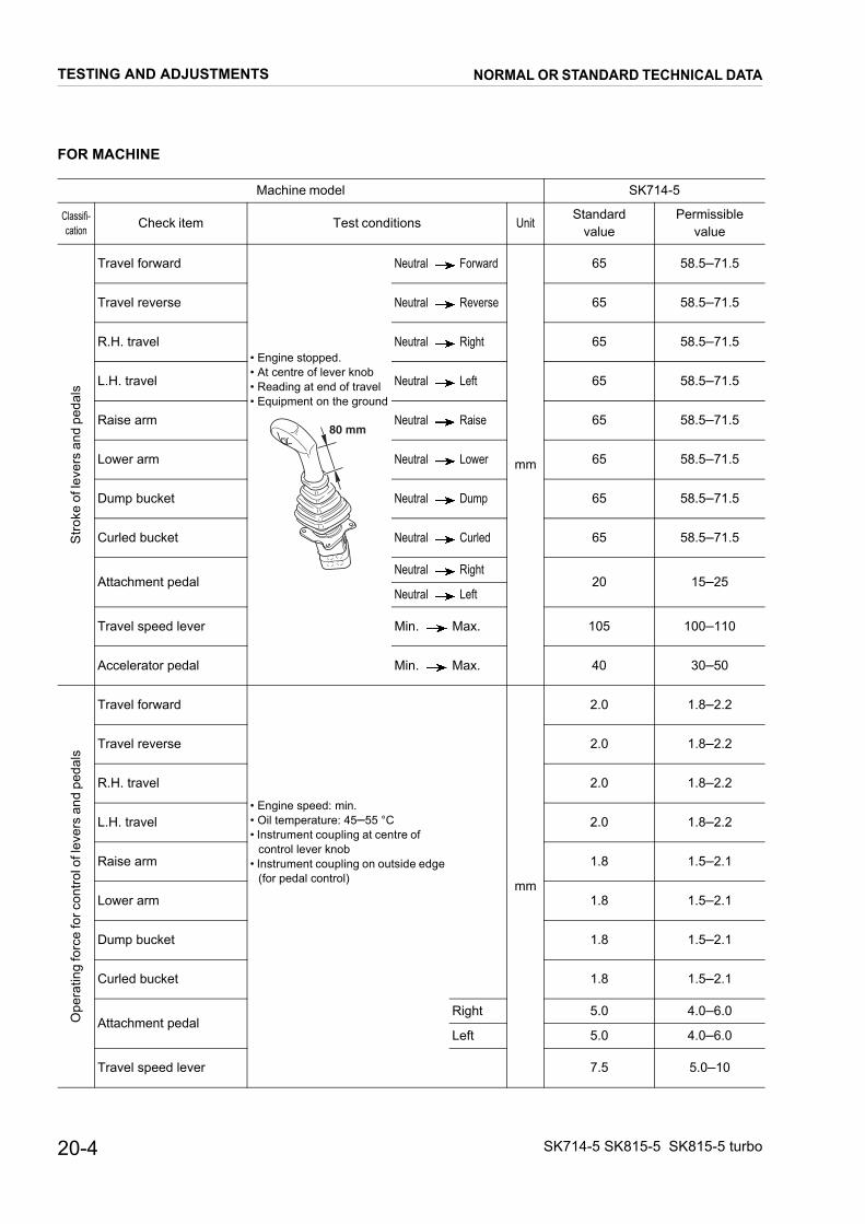
FOR MACHINE
Machine model SK714-5
Classifi-cation Check item Test conditions Unit
Standardvalue
Permissiblevalue
Stro
ke o
f lev
ers
and
peda
ls
Travel forward
• Engine stopped.• At centre of lever knob• Reading at end of travel• Equipment on the ground
Neutral Forward
mm
65 58.5–71.5
Travel reverse Neutral Reverse 65 58.5–71.5
R.H. travel Neutral Right 65 58.5–71.5
L.H. travel Neutral Left 65 58.5–71.5
Raise arm Neutral Raise 65 58.5–71.5
Lower arm Neutral Lower 65 58.5–71.5
Dump bucket Neutral Dump 65 58.5–71.5
Curled bucket Neutral Curled 65 58.5–71.5
Attachment pedalNeutral Right
20 15–25Neutral Left
Travel speed lever Min. Max. 105 100–110
Accelerator pedal Min. Max. 40 30–50
Ope
ratin
g fo
rce
for c
ontro
l of l
ever
s an
d pe
dals
Travel forward
• Engine speed: min.• Oil temperature: 45–55 °C• Instrument coupling at centre of
control lever knob• Instrument coupling on outside edge
(for pedal control) mm
2.0 1.8–2.2
Travel reverse 2.0 1.8–2.2
R.H. travel 2.0 1.8–2.2
L.H. travel 2.0 1.8–2.2
Raise arm 1.8 1.5–2.1
Lower arm 1.8 1.5–2.1
Dump bucket 1.8 1.5–2.1
Curled bucket 1.8 1.5–2.1
Attachment pedalRight 5.0 4.0–6.0
Left 5.0 4.0–6.0
Travel speed lever 7.5 5.0–10
80 mm
TESTING AND ADJUSTMENTS
20-4
NORMAL OR STANDARD TECHNICAL DATA
SK714-5 SK815-5 SK815-5 turbo

TESTING AND ADJUSTMENTS NORMAL OR STANDARD TECHNICAL DATA
FOR MACHINE
SK815-5 SK815-5 turbo
Standardvalue
Permissiblevalue
Standardvalue
Permissiblevalue
65 58.5–71.5 65 58.5–71.5
65 58.5–71.5 65 58.5–71.5
65 58.5–71.5 65 58.5–71.5
65 58.5–71.5 65 58.5–71.5
65 58.5–71.5 65 58.5–71.5
65 58.5–71.5 65 58.5–71.5
65 58.5–71.5 65 58.5–71.5
65 58.5–71.5 65 58.5–71.5
20 15–25 20 15–25
105 100–110 105 100–110
40 30–50 40 30–50
2.0 1.8–2.2 2.0 1.8–2.2
2.0 1.8–2.2 2.0 1.8–2.2
2.0 1.8–2.2 2.0 1.8–2.2
2.0 1.8–2.2 2.0 1.8–2.2
1.8 1.5–2.1 1.8 1.5–2.1
1.8 1.5–2.1 1.8 1.5–2.1
1.8 1.5–2.1 1.8 1.5–2.1
1.8 1.5–2.1 1.8 1.5–2.1
5.0 4.0–6.0 5.0 4.0–6.0
5.0 4.0–6.0 5.0 4.0–6.0
7.5 5.0–10 7.5 5.0–10
20-5SK714-5 SK815-5 SK815-5 turbo

TESTING AND ADJUSTMENTS NORMAL OR STANDARD TECHNICAL DATA
FOR MACHINE
Machine model SK714-5
Classifi-cation Check item Test conditions Unit
Standardvalue
Permissiblevalue
Hyd
raul
ic p
ress
ure
Control valve • Engine speed: 1800±50 rpm• Oil temperature: 45–55 °C
bar
190 180–195
Travel motors(forward)
• Engine speed: 2800±10 rpm• Oil temperature: 45–55 °C• Parking brake: applied• 2nd speed
309 265–316
Travel motors(backward)
• Engine speed: 2800±10 rpm• Parking brake: applied• 2nd speed• Oil temperature: 45–55 °C
309 230–316
Servocontrol • Engine speed: 2800±10 rpm• Oil temperature: 45–55 °C 26 25–30
AS Valve• Machine raised from the ground• Oil temperature: 45–55 °C• Travel levers: forward
Low idling – –
Set speed – –
Unloading valve• Engine speed: max.• Oil temperature: 45–55 °C• Travel levers: at neutral
– –
Pilo
t sys
tem
and
sec
onda
ry c
ircui
t pre
ssur
es
Pilot system travelforward (start-up) ✽
• Engine speed: 2800±10 rpm• Oil temperature: 45–55 °C• Machine raised from the ground
✽ Pressure of wheels start rotation
bar
5.5 4.0–7.0
Pilot system travel(maximum)
14.2 13.8–14.7
Pilot system travelreverse (start-up) ✽
5.5 4.0–7.0
Pilot system travelreverse (maximum)
14.2 13.8–14.7
Pilot system travelto right or left(start-up) ✽
5.5 4.0–7.0
Pilot system travelto right or left(maximum)
14.2 13.8–14.7
Pilot system with parkingbrake disengaged
22 min. 22
Eng
ine
spee
d (w
ith lo
ad)
With travel pump
• Engine speed: max.• Oil temperature: 45–55 °C• 2nd speed• Travel lever: at full stroke• Parking brake: applied
rpm
2800 2800–3000
With travel andequipment pumps
• Engine speed: max.• Oil temperature: 45–55 °C• 2nd speed• Travel lever: at full stroke• Parking brake: applied• Raise: at end of stroke
2150 2150–2500
20-6 SK714-5 SK815-5 SK815-5 turbo

FOR MACHINE
SK815-5 SK815-5 turbo
Standardvalue
Permissiblevalue
Standardvalue
Permissiblevalue
190 180–195 190 180–195
309 265–316 309 265–316
309 230–316 309 230–316
26.5 25–28 26.5 25–28
– – – –
– – – –
– – – –
5.5 4.0–7.0 5.5 4.0–7.0
14.2 13.8–14.7 14.2 13.8–14.7
5.5 4.0–7.0 5.5 4.0–7.0
14.2 13.8–14.7 14.2 13.8–14.7
5.5 4.0–7.0 5.5 4.0–7.0
14.2 13.8–14.7 14.2 13.8–14.7
25 min. 25 25 min. 25
2800 2800–3000 2800 2800–3000
2400 2250–2500 2550 2450–2700
TESTING AND ADJUSTMENTS
SK714-5 SK815-5 SK815-5 turbo
NORMAL OR STANDARD TECHNICAL DATA
20-7

FOR MACHINE
Machine model SK714-5
Classifi-cation Check item Test conditions Unit
Standardvalue
Permissiblevalue
Hyd
raul
ic d
rift o
f wor
k eq
uipm
ent
Fron
t buc
ket
Total work equipment(Downwardmovement of tips ofthe rake blade)
Measuring posture
• In this position, measure extension or retraction ofeach cylinder, and any leakages occurring.
• Horizontal and level ground• Engine: switched off• Oil temperature: 45–55 °C• Release all residual pressure as soon as you stop
the engine.• Take all readings immediately after stopping the
engine and releasing all residual pressure.• Measure the variation 15 minutes after engine
stop.
mm
Max. 130 Max. 130
Raising cylinder(Retraction)
Max. 14 Max. 14
Bucket cylinder(Extension)
Max. 10 Max. 10
RKS01210
TESTING AND ADJUSTMENTS
20-8
NORMAL OR STANDARD TECHNICAL DATA
SK714-5 SK815-5 SK815-5 turbo

FOR MACHINE
SK815-5 SK815-5 turbo
Standardvalue
Permissiblevalue
Standardvalue
Permissiblevalue
Max. 130 Max. 130 Max. 130 Max. 130
Max. 14 Max. 14 Max. 14 Max. 14
Max. 10 Max. 10 Max. 10 Max. 10
TESTING AND ADJUSTMENTS
SK714-5 SK815-5 SK815-5 turbo
NORMAL OR STANDARD TECHNICAL DATA
20-9
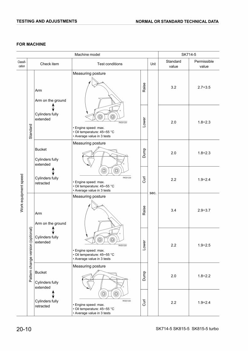
FOR MACHINE
Machine model SK714-5
Classifi-cation Check item Test conditions Unit
Standardvalue
Permissiblevalue
Wor
k eq
uipm
ent s
peed
Sta
ndar
d
Arm
Arm on the ground
Cylinders fullyextended
Measuring posture
• Engine speed: max.• Oil temperature: 45–55 °C• Average value in 3 tests
Rai
se
sec.
3.2 2.7÷3.5
Low
er
2.0 1.8÷2.3
Bucket
Cylinders fullyextended
Cylinders fullyretracted
Measuring posture
• Engine speed: max.• Oil temperature: 45–55 °C• Average value in 3 tests
Dum
p
2.0 1.8÷2.3
Cur
l
2.2 1.9÷2.4
Pat
tern
cha
nge
vers
ion
(opt
iona
l)
Arm
Arm on the ground
Cylinders fullyextended
Measuring posture
• Engine speed: max.• Oil temperature: 45–55 °C• Average value in 3 tests
Rai
se 3.4 2.9÷3.7
Low
er
2.2 1.9÷2.5
Bucket
Cylinders fullyextended
Cylinders fullyretracted
Measuring posture
• Engine speed: max.• Oil temperature: 45–55 °C• Average value in 3 tests
Dum
p
2.0 1.8÷2.2
Cur
l
2.2 1.9÷2.4
RKS01220
RKS01230
RKS01220
RKS01230
TESTING AND ADJUSTMENTS
20-10
NORMAL OR STANDARD TECHNICAL DATA
SK714-5 SK815-5 SK815-5 turbo

20-11SK714-5 SK815-5 SK815-5 turbo
FOR MACHINE
SK815-5 SK815-5 turbo
Standardvalue
Permissiblevalue
Standardvalue
Permissiblevalue
3.2 2.7÷3.5 3.2 2.7÷3.5
2.0 1.8÷2.3 2.0 1.8÷2.3
2.0 1.8÷2.3 2.0 1.8÷2.3
2.2 1.9÷2.4 2.2 1.9÷2.4
3.4 2.9÷3.7 3.4 2.9÷3.7
2.2 1.9÷2.5 2.2 1.9÷2.5
2.0 1.8÷2.2 2.0 1.8÷2.2
2.2 1.9÷2.4 2.2 1.9÷2.4
TESTING AND ADJUSTMENTS NORMAL OR STANDARD TECHNICAL DATA

20-12 SK714-5 SK815-5 SK815-5 turbo
FOR MACHINE
Machine model SK714-5
Classifi-cation Check item Test conditions Unit
Standardvalue
Permissiblevalue
Trav
el
Wheel swing(without load)
Measuring posture
• Engine speed: max.• Oil temperature: 45–55 °C• Machine raised from grouns
Nor
mal
rpm
76 72÷82
With
invr
emen
t
118 110÷126
Travel speed
Measuring posture
• Engine speed: max• Oil temperature: 45–55 °C• Wheel pressure: min. 2.8 bar• Travel 25 meters and then check the time
needed for cover 25 meters.• Check all the direction
Nor
mal
sec.
8.6 8.17÷9.03
With
incr
emen
t
5.6 5.32÷5.88
Travel deviation
Measuring posture
• Engine speed: max.• Oil temperature: 45–55 °C• Wheel pressure: min. 2.8 bar• Travel 20 metres on flat ground and measure the
deviation.• Check all the direction★ The surface must be firm and horizontal.
( ): Value with speed increment
mmMax. 250
(Max. 250)Max. 250
(Max. 250)
RKS01240
RKS01250
RKS01250
10m
20m
X
RKS01710
TESTING AND ADJUSTMENTS NORMAL OR STANDARD TECHNICAL DATA

20-13SK714-5 SK815-5 SK815-5 turbo
FOR MACHINE
SK815-5 SK815-5 turbo
Standardvalue
Permissiblevalue
Standardvalue
Permissiblevalue
76 72÷82 76 72÷82
118 110÷126 118 110÷126
8.6 8.17÷9.03 8.6 8.17÷9.03
5.6 5.32÷5.88 5.6 5.32÷5.88
Max. 250(Max. 250)
Max. 250(Max. 250)
Max. 250(Max. 250)
Max. 250(Max. 250)
TESTING AND ADJUSTMENTS NORMAL OR STANDARD TECHNICAL DATA
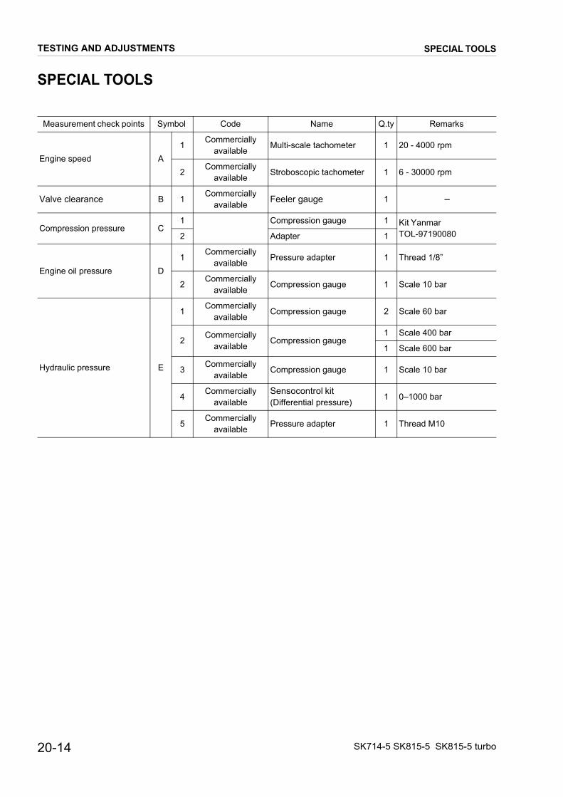
20-14 SK714-5 SK815-5 SK815-5 turbo
SPECIAL TOOLS
Measurement check points Symbol Code Name Q.ty Remarks
Engine speed A1
Commerciallyavailable
Multi-scale tachometer 1 20 - 4000 rpm
2Commercially
availableStroboscopic tachometer 1 6 - 30000 rpm
Valve clearance B 1Commercially
available Feeler gauge 1 --
Compression pressure C1 Compression gauge 1 Kit Yanmar
TOL-971900802 Adapter 1
Engine oil pressure D1
Commerciallyavailable
Pressure adapter 1 Thread 1/8”
2Commercially
availableCompression gauge 1 Scale 10 bar
Hydraulic pressure E
1Commercially
availableCompression gauge 2 Scale 60 bar
2Commercially
availableCompression gauge
1 Scale 400 bar
1 Scale 600 bar
3Commercially
availableCompression gauge 1 Scale 10 bar
4Commercially
availableSensocontrol kit(Differential pressure)
1 0–1000 bar
5Commercially
availablePressure adapter 1 Thread M10
TESTING AND ADJUSTMENTS SPECIAL TOOLS

20-15SK714-5 SK815-5 SK815-5 turbo
CHECKING THE ENGINE SPEED
When checking the engine rpm , always be very carefulnot to touch parts that reach high temperatures and notto get entangled in rotating elements.★ Check the engine speed after the following condi-
tions have been reached:• Temperature of engine cooling water: 68–80 °C.• Oil temperature: 45–55 °C.
1 - Mount and connect the tachometer A1.★ If the stroboscopic tachometer A2 is used, remove
plug (1).
2 - Start the engine and check:• Low idling without load (accelerator lever in “mini-
mum” position).• High idling without load (accelerator lever in “ma-
ximum” position).★ Low idling: 1100±50 rpm
★ High idling: 2975 rpm
★ If the minimum and maximum speeds do not fallwithin permissible limits when the engine is withoutload, check the position locks of the accelerator le-ver, and the sheathing of the accelerator well, be-fore carrying out any tests under load.(See «ADJUSTMENT OF THE ACCELERATORLEVER»).
• Engine rpm with the pumps under load.★ Only for Pattern Change version.
Check that the Pattern change valve is in “ISO” mo-de.
★ Max. speed with parking brake inserted, 2nd speedinserted and travel lever at full stroke (forward):2800–3000 rpm
★ Max. speed with parking brake inserted, 2nd speedinserted, travel lever at full stroke (forward) and rai-sing arm at the end of stroke: SK714-5: 2150–2500 rpmSK815-5: 2250–2500 rpmSK815-5 turbo: 2450–2700 rpm
★ If engine efficiency does not fall within permissiblelimits, have the engine checked by an authorisedworkshop.
��������
��
��������
���
+75- 50
RKS01191
Min Max
TESTING AND ADJUSTMENTS CHECKING THE ENGINE SPEED

20-16 SK714-5 SK815-5 SK815-5 turbo
ADJUSTMENT OF VALVE CLEARANCE (SK714-5 SK815-5)
★ Adjust the clearance between valve and rockers to thefollowing values:
Unit: mm
1 - Remove the air intake filter. (For detail see «30. RE-MOVAL OF AIR INTAKE FILTER».)
2 - Remove the valve cover. (For detail see «30. REMOV-AL OF VALVE COVER».)
3 - Turn the drive shaft in the normal direction of rotationuntil the line (1) marked as no. 1 on the flywheel is in ali-gnment with the reference notch (2) on the flywheelhousing.★ If the cylinder is in a compression stroke, the valves
do not move when the drive shaft is rotated slightly.If the valves do move, rotate the drive shaft by oneturn and realign the reference marks (1) and (2).
4 - Loosen the lock nut (3) and unscrew the adjustmentscrew (4) by approximately 1 turn.★ Check that the valve cap (5) is lying flat on the valve
stem and that there is no lop-sided wear.1 - If the valve caps (5) are damaged, replace them
with new ones.2 - Make sure that the valve caps fit perfectly and are
lying flat on the valve stem.
5 - Insert the feeler gauge B1 between the rocker (6) andthe valve cap (5).Rotate the adjusting screw (4) until it rubs against the fe-eler gauge B1.Secure this position with the nut (3).
Lock nut: 25.5±2.5 Nm
★ After locking the nut (3), check the valve clearanceagain.
6 - After adjusting the No. 1 cylinder, rotate the drive shaft180° each time and adjust the valve clearance of theother cylinders according to the ignition sequence.★ Ignition sequence: 1 - 3 - 4 - 2.
Assembly of the valve cover
1 - Check the condition of the gasket (7) of the valve cover (8), and the O-rings (9). Thoroughly clean the contactsurface on the cylinder heads.
2 - Replace the valve cover (8) and mount the O-rings (9)and the lock nuts (10).
Lock nuts for cover: 25±3 Nm
Withengine cold
Suction valves Exhaust valves
0.20 0.20
������
��
5
YES NO
4
3
5
6
RKS01681
��������
��
8
9
RKS03910
10
7
TESTING AND ADJUSTMENTS ADJUSTMENT OF VALVE CLEARANCE
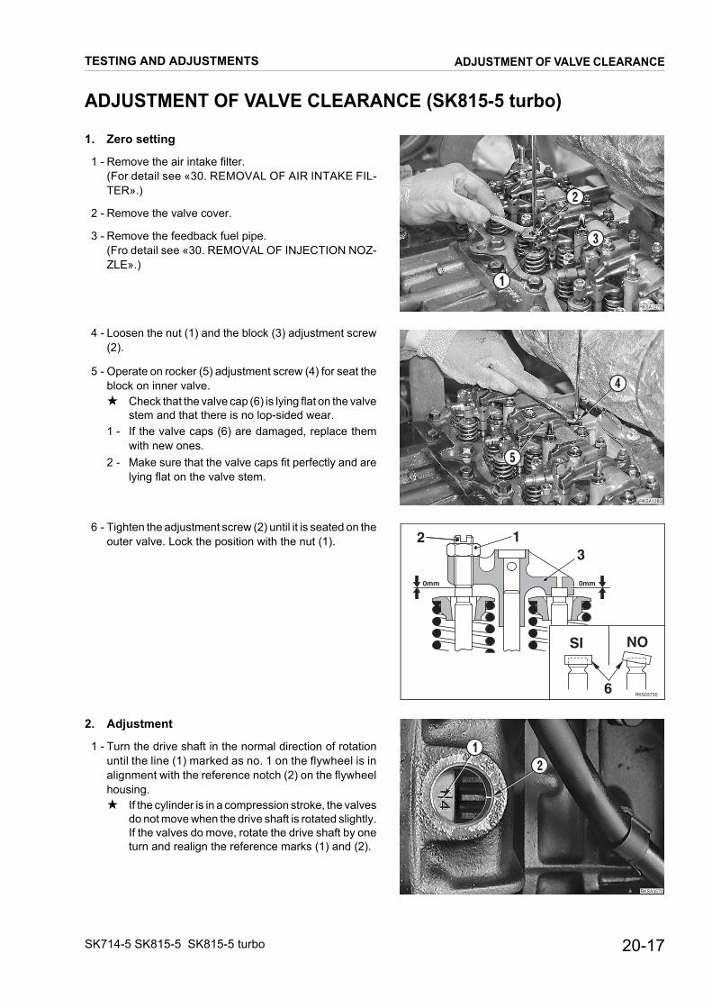
20-17SK714-5 SK815-5 SK815-5 turbo
ADJUSTMENT OF VALVE CLEARANCE (SK815-5 turbo)
1. Zero setting
1 - Remove the air intake filter.(For detail see «30. REMOVAL OF AIR INTAKE FIL-TER».)
2 - Remove the valve cover.
3 - Remove the feedback fuel pipe.(Fro detail see «30. REMOVAL OF INJECTION NOZ-ZLE».)
4 - Loosen the nut (1) and the block (3) adjustment screw(2).
5 - Operate on rocker (5) adjustment screw (4) for seat theblock on inner valve.★ Check that the valve cap (6) is lying flat on the valve
stem and that there is no lop-sided wear.1 - If the valve caps (6) are damaged, replace them
with new ones.2 - Make sure that the valve caps fit perfectly and are
lying flat on the valve stem.
6 - Tighten the adjustment screw (2) until it is seated on theouter valve. Lock the position with the nut (1).
2. Adjustment
1 - Turn the drive shaft in the normal direction of rotationuntil the line (1) marked as no. 1 on the flywheel is inalignment with the reference notch (2) on the flywheelhousing.★ If the cylinder is in a compression stroke, the valves
do not move when the drive shaft is rotated slightly.If the valves do move, rotate the drive shaft by oneturn and realign the reference marks (1) and (2).
RKSA1270
1
3
2
RKSA1280
5
4
�� ��
��
�
�
��������
��������
��
TESTING AND ADJUSTMENTS ADJUSTMENT OF VALVE CLEARANCE

20-18 SK714-5 SK815-5 SK815-5 turbo
2 - Loosen the lock nut (3) and unscrew the adjustmentscrew (4) by approximately 1 turn.
3 - Insert the feeler gauge B1 between the rocker (6) andthe valve cap (5).Rotate the adjusting screw (4) until it rubs against the fe-eler gauge B1.Secure this position with the nut (3).★ After locking the nut (3), check the valve clearance
again.
4 - Adjust the clearance between valve and rockers to thefollowing values:
Unit: mm
5 - After adjusting the No. 1 cylinder, rotate the drive shaft180° each time and adjust the valve clearance of theother cylinders according to the ignition sequence.★ Ignition sequence: 1 - 3 - 4 - 2.
Withengine cold
Suction valves Exhaust valves
0.20 0.20
RKSA1300
35
6
B1
4
�����
�
�
TESTING AND ADJUSTMENTS ADJUSTMENT OF VALVE CLEARANCE

20-19SK714-5 SK815-5 SK815-5 turbo
MEASUREMENT OF THE COMPRESSION PRESSURE(SK714-5 SK815-5)
While measuring the compression, take care not to getentangled in the cooling fan, the alternator belt, or inother rotating parts.Check all cylinders.
★ Test conditions:• Engine: at working temperature.• Olio idraulico: 45–55°C.• Battery: fully charged.• Valve clearance: adjusted
(See «ADJUSTMENT OF VALVE CLEARAN-CE»).
1 - Remove air filter with support.
2 - Disconnect the high-pressure tube (1).
3 - Remove the nozzle holder (2) of the cylinder to be che-cked.
4 - Disconnect the connector (3) of the engine-stopping so-lenoid and close the fuel cock (4).
5 - Turn the engine over a few times, using the starting mo-tor.
6 - Mount the adapter C2 and connect the test pressuregauge C1.★ Check that the seal is mounted in the adapter, and
that it is undamaged.
7 - Turn the engine using the starting motor and read thecompression value.★ Read the compression value when the pressure
gauge has stabilised.★ While reading the compression, also check the en-
gine rpm using the tachometer A1 or A2. If the spe-ed does not correspond with the control value,check it against the diagram.
★ Compression value:Normal: 35±1 kg/cm² at 250 rpmMinimum permissible: 28±1 kg/cm² at 250 rpm
★ Maximum difference between the cylinders:2–3 kg/cm²
8 - After the reading, re-assemble the nozzle holder (2),and reconnect the high- pressure tube (1) and the con-nector (3).
Nut that secures the nozzle: 7.84±0.98 Nm
High-pressure coupling: 31.85±2.45 Nm
RKSA0040
1
2
��������
�
�
RKSA0060
C2
C1
��������
��
��
��
��
��
��� ��� ��� ��� ���
������ ���� ��
��
�
���
��
� �
���
���
���
�� �
TESTING AND ADJUSTMENTS MEASUREMENT OF THE COMPRESSION PRESSURE
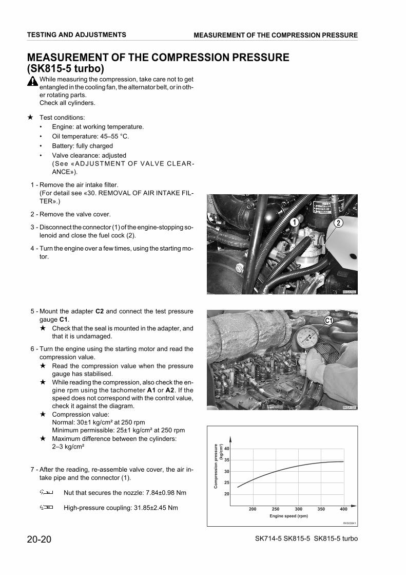
20-20 SK714-5 SK815-5 SK815-5 turbo
MEASUREMENT OF THE COMPRESSION PRESSURE(SK815-5 turbo)
While measuring the compression, take care not to getentangled in the cooling fan, the alternator belt, or in oth-er rotating parts.Check all cylinders.
★ Test conditions:• Engine: at working temperature.• Oil temperature: 45–55 °C.• Battery: fully charged• Valve clearance: adjusted
(See «ADJUSTMENT OF VALVE CLEAR-ANCE»).
1 - Remove the air intake filter.(For detail see «30. REMOVAL OF AIR INTAKE FIL-TER».)
2 - Remove the valve cover.
3 - Disconnect the connector (1) of the engine-stopping so-lenoid and close the fuel cock (2).
4 - Turn the engine over a few times, using the starting mo-tor.
5 - Mount the adapter C2 and connect the test pressuregauge C1.★ Check that the seal is mounted in the adapter, and
that it is undamaged.
6 - Turn the engine using the starting motor and read thecompression value.★ Read the compression value when the pressure
gauge has stabilised.★ While reading the compression, also check the en-
gine rpm using the tachometer A1 or A2. If thespeed does not correspond with the control value,check it against the diagram.
★ Compression value:Normal: 30±1 kg/cm² at 250 rpmMinimum permissible: 25±1 kg/cm² at 250 rpm
★ Maximum difference between the cylinders:2–3 kg/cm²
7 - After the reading, re-assemble valve cover, the air in-take pipe and the connector (1).
Nut that secures the nozzle: 7.84±0.98 Nm
High-pressure coupling: 31.85±2.45 Nm
�������
��
RKSA1320
C1
��������
��
��
��
��
��
��� ��� ��� ��� ���
������ ���� ��
��
�
���
��
� �
���
���
���
�� �
TESTING AND ADJUSTMENTS MEASUREMENT OF THE COMPRESSION PRESSURE
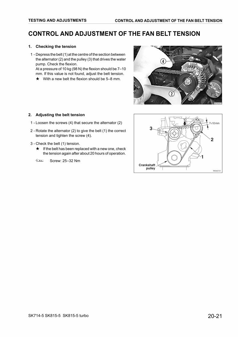
20-21SK714-5 SK815-5 SK815-5 turbo
CONTROL AND ADJUSTMENT OF THE FAN BELT TENSION
1. Checking the tension
1 - Depress the belt (1) at the centre of the section between the alternator (2) and the pulley (3) that drives the waterpump. Check the flexion.At a pressure of 10 kg (98 N) the flexion should be 7–10mm. If this value is not found, adjust the belt tension.★ With a new belt the flexion should be 5–8 mm.
2. Adjusting the belt tension
1 - Loosen the screws (4) that secure the alternator (2)
2 - Rotate the alternator (2) to give the belt (1) the correcttension and tighten the screw (4).
3 - Check the belt (1) tension.★ If the belt has been replaced with a new one, check
the tension again after about 20 hours of operation.
Screw: 25–32 Nm
��������
�
�
������
���� ��
������������ �
�
�
�
TESTING AND ADJUSTMENTS CONTROL AND ADJUSTMENT OF THE FAN BELT TENSION
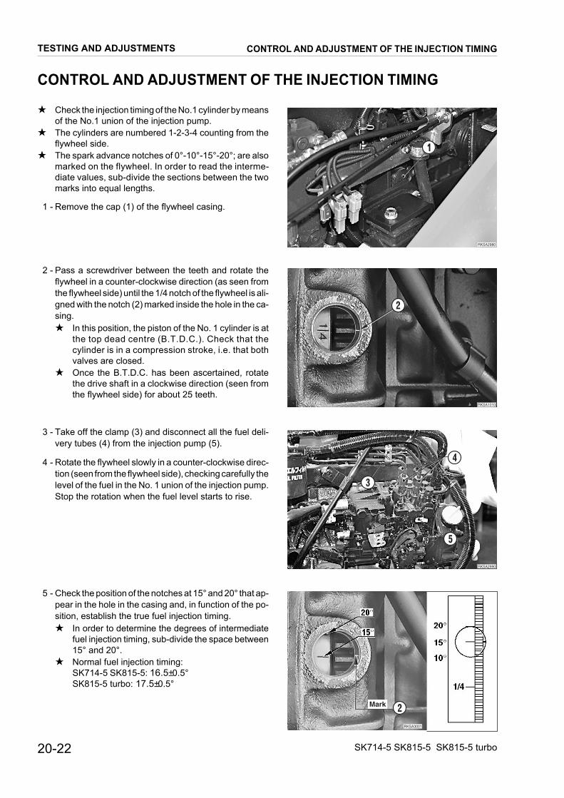
20-22 SK714-5 SK815-5 SK815-5 turbo
CONTROL AND ADJUSTMENT OF THE INJECTION TIMING
★ Check the injection timing of the No.1 cylinder by meansof the No.1 union of the injection pump.
★ The cylinders are numbered 1-2-3-4 counting from theflywheel side.
★ The spark advance notches of 0°-10°-15°-20°; are alsomarked on the flywheel. In order to read the interme-diate values, sub-divide the sections between the twomarks into equal lengths.
1 - Remove the cap (1) of the flywheel casing.
2 - Pass a screwdriver between the teeth and rotate theflywheel in a counter-clockwise direction (as seen fromthe flywheel side) until the 1/4 notch of the flywheel is ali-gned with the notch (2) marked inside the hole in the ca-sing.★ In this position, the piston of the No. 1 cylinder is at
the top dead centre (B.T.D.C.). Check that thecylinder is in a compression stroke, i.e. that bothvalves are closed.
★ Once the B.T.D.C. has been ascertained, rotatethe drive shaft in a clockwise direction (seen fromthe flywheel side) for about 25 teeth.
3 - Take off the clamp (3) and disconnect all the fuel deli-very tubes (4) from the injection pump (5).
4 - Rotate the flywheel slowly in a counter-clockwise direc-tion (seen from the flywheel side), checking carefully thelevel of the fuel in the No. 1 union of the injection pump.Stop the rotation when the fuel level starts to rise.
5 - Check the position of the notches at 15° and 20° that ap-pear in the hole in the casing and, in function of the po-sition, establish the true fuel injection timing.★ In order to determine the degrees of intermediate
fuel injection timing, sub-divide the space between15° and 20°.
★ Normal fuel injection timing: SK714-5 SK815-5: 16.5±0.5°SK815-5 turbo: 17.5±0.5°
��������
�
RKSA1010
2
��������
�
�
�
�������������
���� �
TESTING AND ADJUSTMENTS CONTROL AND ADJUSTMENT OF THE INJECTION TIMING
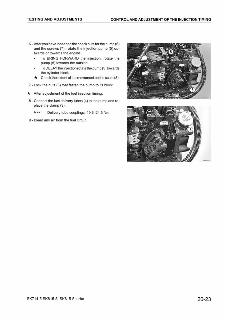
20-23SK714-5 SK815-5 SK815-5 turbo
6 - After you have loosened the check nuts for the pump (6)and the screws (7), rotate the injection pump (5) ou-twards or towards the engine. • To BRING FORWARD the injection, rotate the
pump (5) towards the outside.• To DELAY the injection rotate the pump (5) towards
the cylinder block.★ Check the extent of the movement on the scale (8).
7 - Lock the nuts (6) that fasten the pump to its block.
★ After adjustment of the fuel injection timing:
8 - Connect the fuel delivery tubes (4) to the pump and re-place the clamp (3).
Delivery tube couplings: 19.6–24.5 Nm
9 - Bleed any air from the fuel circuit.
��������
�
�
�
��������
�
TESTING AND ADJUSTMENTS CONTROL AND ADJUSTMENT OF THE INJECTION TIMING

20-24 SK714-5 SK815-5 SK815-5 turbo
CHECKING ENGINE OIL PRESSURE
When measuring the engine oil pressure, take greatcare not to touch high-temperature parts, or to becomeentangled in rotating elements.
★ Check pressure with the engine at working temperatu-re.
★ Low and high idling within permissible limits.
1 - Start the engine and wait for it to reach working tempe-rature.★ Working temperature:
Coolant liquid: 90°CEngine oil: 80°C
2 - Stop the engine and remove the oil pressure sensor (1).
3 - Mount the adapter D1 and connect the pressure gaugeD2.
4 - Start the engine and check the oil pressure at low idling(accelerator lever in low idling position) and at highidling ((accelerator lever in high idling position).★ Low idling pressure: >0.6 kg/cm2
★ High idling pressure: 3.0–4.0 kg/cm2
5 - Remove the adapter D1 and install the oil pressure sen-sor (1).
������
�
��������
��
��
TESTING AND ADJUSTMENTS CHECKING ENGINE OIL PRESSURE
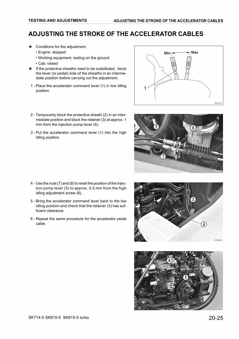
20-25SK714-5 SK815-5 SK815-5 turbo
ADJUSTING THE STROKE OF THE ACCELERATOR CABLES
★ Conditions for the adjustment:• Engine: stopped• Working equipment: resting on the ground• Cab: raised
★ If the protective sheaths need to be substituted, blockthe lever (or pedal) side of the sheaths in an interme-diate position before carrying out the adjustment.
1 - Place the accelerator command lever (1) in low idlingposition.
2 - Temporarily block the protective sheath (2) in an inter-mediate position and block the retainer (3) at approx. 1mm from the injection pump lever (4).
3 - Put the accelerator command lever (1) into the highidling position.
4 - Use the nuts (7) and (8) to reset the position of the injec-tion pump lever (5) to approx. 0.5 mm from the highidling adjustment screw (6).
5 - Bring the accelerator command lever back to the lowidling position and check that the retainer (3) has suf-ficient clearance.
6 - Repeat the same procedure for the accelerator pedalcable.
RKS01190
Min Max
1
������
�
�
�
������
�
�
�������
�
�
TESTING AND ADJUSTMENTS ADJUSTING THE STROKE OF THE ACCELERATOR CABLES

20-26 SK714-5 SK815-5 SK815-5 turbo
REGULATION OF PPC VALVES’ DRIVE PRESSURE
★ Regulate the PPC valves’ drive pressure by performingthe following steps.
1 - Lower the working equipment to the ground andstop the engine.
2 - Turn the ignition key to the I position and shift thecontrol levers in all directions to release the hy-draulic circuit pressure completely.
3 - Turn the ignition key to the O (OFF) position and re-move the ignition key.Gently loosen the oil fill cap to eliminate any resid-ual pressure.
Disassembly and regulation
1 - Remove the complete PPC VALVE.(For details, please refer to section 30 «REMOVAL OFPPC VALVES»).
2 - Lift the boot (1) and mark the position of the lever (2) inrelation to the PPC valve body (3).
3 - Loosen the screw (4), remove the washer (5) and pullout the complete handle (6).
4 - Remove the joint (7) and retainer plate (8).
5 - Remove the boot (9) and remove the O-ring (10).
RKSA2360
12
3
RKSA2370
6
5
4
1
RKSA2380
7
8
9
10
2
TESTING AND ADJUSTMENTS REGULATION OF PPC VALVES’ DRIVE PRESSURE

20-27SK714-5 SK815-5 SK815-5 turbo
6 - Loosen the 4 retaining screws (11) from the plate (12)and remove the plate.
7 - Remove the stopper (13) and seals.
★ Use a soft tool to remove.
8 - Remove the complete spool (14).
9 - Remove the retainer (15), spring (16) and shims (17)from the spool (14).
10 - Add shims until you reach the admitted calibration va-lue; bear in mind that 0.3 mm thickness corresponds toa variation in pressure of about 0.6 bar. (For details, ple-ase refer to «TECHNICAL DATA»).
Assembly• To assemble, perform the disassembly procedure in the
reverse order.★ Thoroughly clean all parts.
Cleaner: Loctite 7063
Screw: 64–74 Nm
★ Press down on the stoppers (13) to ease settinginto place; tighten the retainer plate (8) until it is pro-perly seated and adjust clearance. (For details, ple-ase re fe r to «PPC VALVE CLEARANCEADJUSTMENT»).
Joint: 112.8±14.7 Nm
Screws: 13.2±1.5 Nm
★ Lubricate the stoppers (13).
RKSA2390
11
12
3
RKSA2400
13 144
RKSA2410
14
15 1617
1
2
3
4
TESTING AND ADJUSTMENTS REGULATION OF PPC VALVES’ DRIVE PRESSURE

20-28 SK714-5 SK815-5 SK815-5 turbo
ADJUSTMENT OF THE PPC VALVE CLEARANCES
The clearance of the PPC valve (hand and foot) levers isadjusted as follows.
Lower the working equipment to the ground and stopthe engine.Turn the ignition key to the I position and move the com-mand levers in all directions in order to release all pres-sure in the hydraulic circuits.Return the ignition key to the O (OFF) position and re-move it.Slowly loosen the oil-tank refuelling cap to eliminate re-sidual pressure.
1 - Remove cap (1).
2 - Loosen the nut (2) that retains the disc (3).
3 - Tighten the disc (3) until it makes light contact with the 4push-rods (4).★ During this adjustment, take care not to activate
any of the push-rods (4) individually.
4 - Secure this position by tightening the retaining nut (2) tothe specific torque.
Retaining nut: 113±15 NmRKS01700
�
�
�
�
TESTING AND ADJUSTMENTS ADJUSTMENT OF THE PPC VALVE CLEARANCES

20-29SK714-5 SK815-5 SK815-5 turbo
ADJUSTING THE POSITION OF THE SERVO-CONTROLENGAGEMENT SAFETY SENSOR
Lower the working equipment to the ground, stop theengine and remove starter key.
1 - Lower the LH safety bar (1) and adjust the position of thesensor (2) by loosening and tightening the adjustmentnuts (3).★ Distance between safety bar and sensor: 1 mm
RKSA0140
1
2
RKS01260
2 3
1
1mm
TESTING AND ADJUSTMENTSADJUSTING THE POSITION OF THE SERVO-CONTROL
ENGAGEMENT SAFETY SENSOR

20-30 SK714-5 SK815-5 SK815-5 turbo
TESTING AND ADJUSTMENT OF GEARING CHAIN TENSION
1. Test★ Test conditions:
• Machine: raised from the ground• Working equipment: in road-driving position
★ Check all the wheels.
1 - Position a magnetic comparator to correspond with thewheel diameter of 600 mm and make a notch “A” closeto the indicator.
2 - Rotate the tire by hand in both directions and check thatthe total displacement of the notch remains within per-missible limits.★ Standard displacement: 4 mm★ Permissible displacement: 2–6 mm
2. Adjustment★ For greater clarity, the photo opposite shows the adju-
stment operations with the tire removed.It is not necessary to remove the tires for this adjust-ment.
1 - Screw a screw A (M10x50, fully threaded) into the holeprovided on the frame until it makes firm contact with thewheel hub.
2 - Loosen the retaining screws (1) of the wheel hub until itcan move.
3 - Gradually tighten the screw A until correct tension hasbeen restored to the chain.
4 - Tighten the nuts (1).
Nuts: 200 Nm
��������
�
���
���
��������
� ������
����
RKSA0170
A
1
TESTING AND ADJUSTMENTS TESTING AND ADJUSTMENT OF GEARING CHAIN TENSION

20-31SK714-5 SK815-5 SK815-5 turbo
TESTING AND ADJUSTMENTSCONTROL AND REGULATION OF THE PRESSURES
IN THE HYDRAULIC CIRCUITS
CONTROL AND REGULATION OF THE PRESSURES IN THEHYDRAULIC CIRCUITS
• The control valve consists of the spools that command:
Command Ports
Arm (Lower - Raise) A1 - B1
Bucket (Dump - Curled) A2 - B2
Equipment (R.H. - L.H.) A3 - B3
★ Test conditions:• Engine: at working temperature.• MIN and MAX. engine speeds: within permissible
limits.• Oil temperature: 45–55 °C.
Before removing the plugs in order to measure thepressures, release the residual pressures in the cir-
cuits (see «ELIMINATION OF THE RESIDUALPRESSURES IN THE CIRCUITS AND IN THETANK») and place the safety engagement levers intotheir locked positions.
After having connected the pressure gauges, pres-surise the tank. For details, see «PRESSURISATIONOF THE TANK».
RKS01291
L.H. TRAVEL MOTOR
CONTROL VALVE
P1 P2 P3 P4 P5
R.H. TRAVEL MOTOR
ENGINE
RKS01130
1
2
3
B A
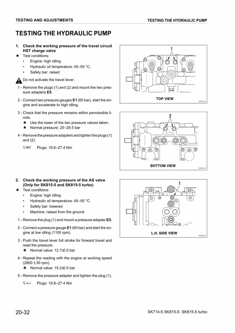
20-32 SK714-5 SK815-5 SK815-5 turbo
TESTING THE HYDRAULIC PUMP
1. Check the working pressure of the travel circuitHST charge valve
★ Test conditions:• Engine: high idling• Hydraulic oil temperature: 45–55 °C.• Safety bar: raised
Do not activate the travel lever.
1 - Remove the plugs (1) and (2) and mount the two pres-sure adapters E5.
2 - Connect two pressure gauges E1 (60 bar), start the en-gine and accelerate to high idling.
3 - Check that the pressure remains within permissible li-mits.★ Use the lower of the two pressure values taken.★ Normal pressure: 25–29.5 bar
4 - Remove the pressure adapters and tighten the plugs (1)and (2).
Plugs: 19.6–27.4 Nm
2. Check the working pressure of the AS valve(Only for SK815-5 and SK815-5 turbo)
★ Test conditions:• Engine: high idling• Hydraulic oil temperature: 45–55 °C.• Safety bar: lowered• Machine: raised from the ground
1 - Remove the plug (1) and mount a pressure adapter E5.
2 - Connect a pressure gauge E1 (60 bar) and start the en-gine at low idling (1100 rpm).
3 - Push the travel lever full stroke for forward travel andread the pressure.★ Normal value: 12.7±0.5 bar
4 - Repeat the reading with the engine at working speed(2800 ± 30 rpm).★ Normal value: 15.2±0.5 bar
5 - Remove the pressure adapter and tighten the plug (1).
Plugs: 19.8–27.4 Nm
RKS01300
1
TOP VIEW
RKS01310
2
BOTTOM VIEW
RKS01320
1
L.H. SIDE VIEW
TESTING AND ADJUSTMENTS TESTING THE HYDRAULIC PUMP

20-33SK714-5 SK815-5 SK815-5 turbo
VALVE CALIBRATION
1. HST valve calibration
1 - Loosen the nut (1), taking care not to move the adjust-ment screw (2).
2 - Adjust the working pressure of the HST valve, procee-ding as follows:• To INCREASE pressure, turn the screw (2) in a
CLOCKWISE direction.• To REDUCE pressure, turn the screw (2) in a
COUNTER-CLOCKWISE direction.★ One complete turn of the screw (2) varies the pres-
sure by 15.5 bar.
3 - Tighten the nut (1) and check that the working pressureremains within permissible limits.
Nut: 58.8–78.5 Nm
2. AS valve calibration(only for SK815-5 and SK815-5 turbo)
• Pressure adjustment at low idling
1 - Loosen the nut (1), and adjust the working pressure ofthe AS valve (with the engine at low idling), proceedingas follows:• To INCREASE pressure, turn the screw (2) in a
CLOCKWISE direction.• To REDUCE pressure, turn the screw (2) in a
COUNTER-CLOCKWISE direction.★ One complete turn of the screw (2) varies the pres-
sure by 3.37 bar.
3 - Tighten the nut (1) and check that the working pressureremains within permissible limits.
Nut: 34.3–58.8 Nm
RKS01330
A
A
TOP VIEW
RKS01340
2 1
Section A - A
RKS01350
A
A
RKS01360
1 2
Section A - A
TESTING AND ADJUSTMENTS VALVE CALIBRATION

20-34 SK714-5 SK815-5 SK815-5 turbo
• Pressure adjustment at working pressure
1 - Loosen the nut (3),. and adjust the working pressure ofthe AS valve (with the engine at working pressure), pro-ceeding as follows:• To INCREASE pressure, turn the screw (4) in a
CLOCKWISE direction.• To REDUCE pressure, turn the screw (4) in a
COUNTER-CLOCKWISE direction.★ One complete turn of the screw (4) varies the pres-
sure by 1.96 bar.
3 - Tighten the nut (3) and check that the working pressureremains within permissible limits.
Nut: 34.3–58.8 Nm
RKS01361
34
Section A - A
TESTING AND ADJUSTMENTS VALVE CALIBRATION

20-35SK714-5 SK815-5 SK815-5 turbo
CHECKING THE TRAVEL DEVIATION
★ Test conditions:• Engine: at max. speed• Hydraulic oil temperature: 45–55 °C.
★ Drive the machine onto solid, level ground.
1. Checking the deviation
1 - Position the boom and bucket in their travelling posi-tions.★ Boom lowered and bucket fully curled.
2 - Bring the engine up to maximum rpm.
3 - Push the travel lever to full stroke forwards
4 - Travel for 5 metres, then measure the deviation of themachine over the next 20 metres.
5 - Check the deviation also in reverse gear and while ac-celerating in both directions.
RKS01270
��������
���
����
����
������ ������� ������
���� ������������
TESTING AND ADJUSTMENTS CHECKING THE TRAVEL DEVIATION
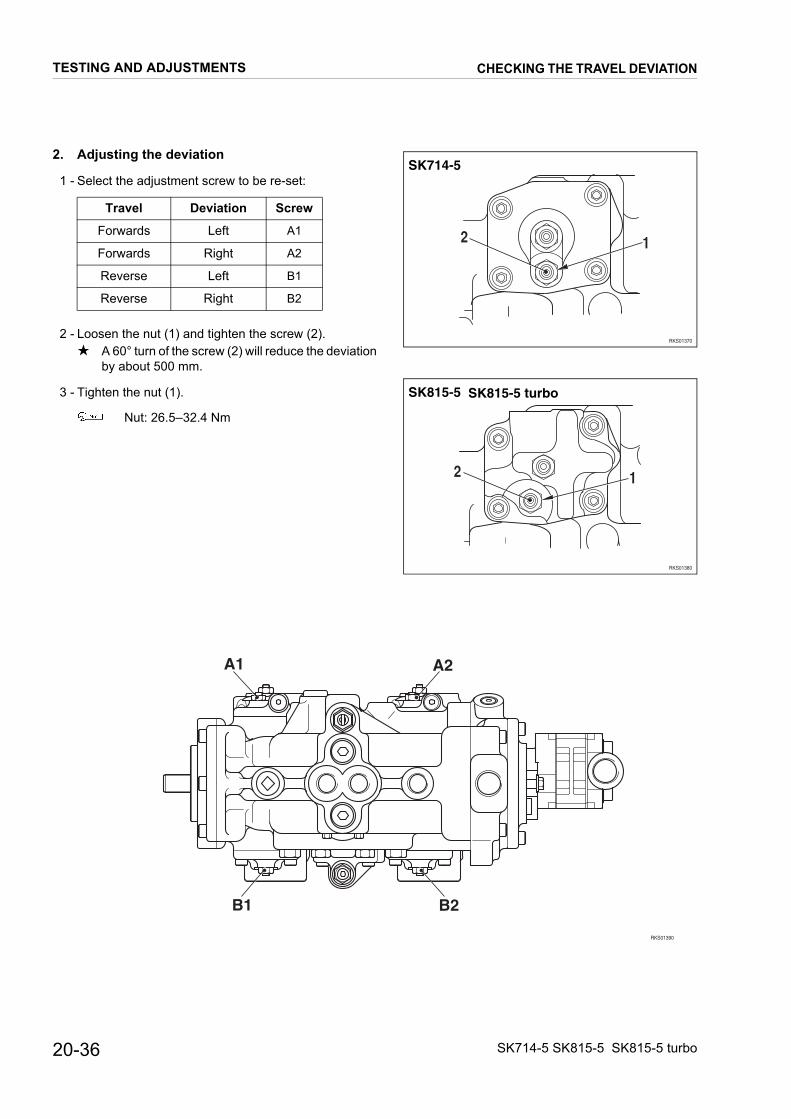
20-36 SK714-5 SK815-5 SK815-5 turbo
2. Adjusting the deviation
1 - Select the adjustment screw to be re-set:
2 - Loosen the nut (1) and tighten the screw (2).★ A 60° turn of the screw (2) will reduce the deviation
by about 500 mm.
3 - Tighten the nut (1).
Nut: 26.5–32.4 Nm
Travel Deviation Screw
Forwards Left A1
Forwards Right A2
Reverse Left B1
Reverse Right B2
RKS01370
12
SK714-5
RKS01380
12
SK815-5 SK815-5 turbo
RKS01390
A1 A2
B2B1
TESTING AND ADJUSTMENTS CHECKING THE TRAVEL DEVIATION

20-37SK714-5 SK815-5 SK815-5 turbo
CONTROL VALVE
1. Control of operating pressure (unloading valve)
1 - Remove the plug (1) and mount a pressure adapter.
2 - Connect a pressure gauge E3 (10 bar).
3 - Start the engine and bring it up to high idling with all le-vers in neutral position.
4 - Check the pressure.★ Normal pressure: 4.8 bar
tTake care do not operate the equipment levers.The unloading valve cannot be re-adjusted. If thepressure differs from the normal value the valvemust be substituted.
2. Control the operating pressures of the workingequipment
1 - Remove the plug (1) and mount a pressure adapter.
2 - Connect a pressure gauge E2 (400 bar or 600 bar).
3 - Start the engine and bring it up to high idling.
4 - Check the pressure for each movement with the com-mand lever at the end of its stroke and with the pressurestabilised.
To check the pressure of the working equipment,push the piston to the end of its stroke.
Valve adjustment★ The unloading valve cannot be re-adjusted, only sub-
stituted.
1. Adjustment of the main relief valveIf the pressures measured for the working equipment andmachine travel do not fall within normal values, adjust themain relief valve (1) as follows:
1 - Loosen the lock nut (2) and rotate the adjusting screw(3).• To INCREASE pressure, turn in a CLOCKWISE di-
rection.• To DECREASE pressure, turn in a COUNTER-
CLOCKWISE direction.★ Each turn of the adjusting screw (3) varies the pres-
sure by about 55 bar.
2 - Lock the nut (2).
Nut: 69±10 Nm
★ After adjustment, check the adjustment of the mainrelief valve with the same procedures as used forthe measurements.
RKSA0180
1
E3
RKSA0190
1
E2
RKS01400
A
1
2
3
A
Section A - A
TESTING AND ADJUSTMENTS CONTROL VALVE
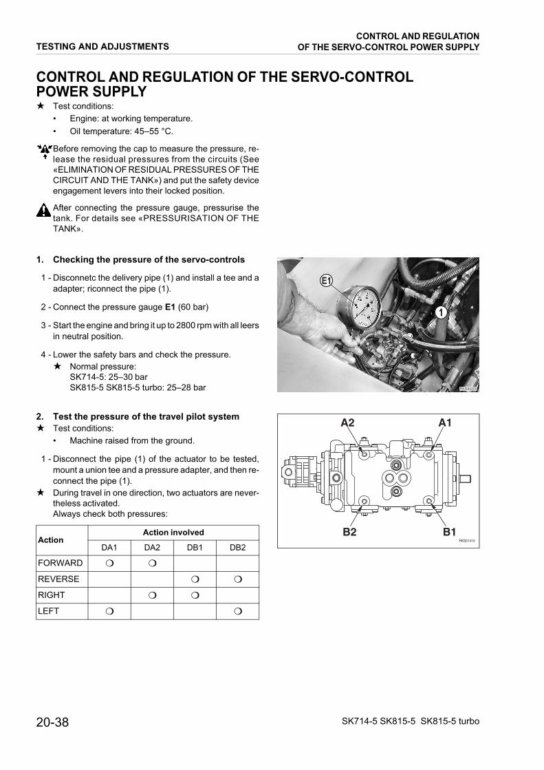
20-38 SK714-5 SK815-5 SK815-5 turbo
CONTROL AND REGULATION OF THE SERVO-CONTROLPOWER SUPPLY★ Test conditions:
• Engine: at working temperature.• Oil temperature: 45–55 °C.
Before removing the cap to measure the pressure, re-lease the residual pressures from the circuits (See«ELIMINATION OF RESIDUAL PRESSURES OF THECIRCUIT AND THE TANK») and put the safety deviceengagement levers into their locked position.
After connecting the pressure gauge, pressurise thetank. For details see «PRESSURISATION OF THETANK».
1. Checking the pressure of the servo-controls
1 - Disconnetc the delivery pipe (1) and install a tee and aadapter; riconnect the pipe (1).
2 - Connect the pressure gauge E1 (60 bar)
3 - Start the engine and bring it up to 2800 rpm with all leersin neutral position.
4 - Lower the safety bars and check the pressure.★ Normal pressure:
SK714-5: 25–30 barSK815-5 SK815-5 turbo: 25–28 bar
2. Test the pressure of the travel pilot system★ Test conditions:
• Machine raised from the ground.
1 - Disconnect the pipe (1) of the actuator to be tested,mount a union tee and a pressure adapter, and then re-connect the pipe (1).
★ During travel in one direction, two actuators are never-theless activated.Always check both pressures:
ActionAction involved
DA1 DA2 DB1 DB2
FORWARD ❍ ❍
REVERSE ❍ ❍
RIGHT ❍ ❍
LEFT ❍ ❍
RKSA0200
1
E1
RKS01410
A2 A1
B2 B1
TESTING AND ADJUSTMENTSCONTROL AND REGULATION
OF THE SERVO-CONTROL POWER SUPPLY
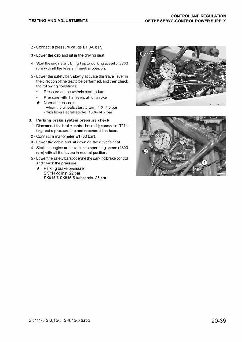
20-39SK714-5 SK815-5 SK815-5 turbo
2 - Connect a pressure gauge E1 (60 bar)
3 - Lower the cab and sit in the driving seat.
4 - Start the engine and bring it up to working speed of 2800rpm with all the levers in neutral position.
5 - Lower the safety bar, slowly activate the travel lever inthe direction of the test to be performed, and then checkthe following conditions:• Pressure as the wheels start to turn• Pressure with the levers at full stroke★ Normal pressures:
- when the wheels start to turn: 4.0–7.0 bar- with levers at full stroke: 13.8–14.7 bar
3. Parking brake system pressure check1 - Disconnect the brake control hose (1); connect a “T” fit-
ting and a pressure tap and reconnect the hose.2 - Connect a manometer E1 (60 bar).3 - Lower the cabin and sit down on the driver’s seat.4 - Start the engine and rev it up to operating speed (2800
rpm) with all the levers in neutral position.5 - Lower the safety bars; operate the parking brake control
and check the pressure.★ Parking brake pressure:
SK714-5: min. 22 barSK815-5 SK815-5 turbo: min. 25 bar
RKSA0210
E1
RKSA1480
E1
1
TESTING AND ADJUSTMENTSCONTROL AND REGULATION
OF THE SERVO-CONTROL POWER SUPPLY

20-40 SK714-5 SK815-5 SK815-5 turbo
ELIMINATION OF RESIDUAL PRESSURES - PRESSURISATION OFTHE TANK1. Elimination of pressures from the hydraulic cir-
cuits.
1 - Rest the working equipment on the ground and stop theengine.
2 - Turn the ignition key to the position I and, with safetybars lower, move the command lever in all directions torelease all pressure in the main hydraulic circuits andthe servo-controls .
3 - Return the ignition key to the position O (OFF) and re-move it.
2. Elimination of pressure in the tank
The hydraulic oil tank is of the sealed and pressurisedtype.When tubes are to be removed or disconnected for con-trols or repairs, or when caps are removed, tank pres-sure must be eliminated using the following method:
1 - Rest the working equipment on the ground and stop theengine.
2 - Slowly loosen the oil-refuelling cap (1) in order to rele-ase residual pressure.
3. Pressurising the tank★ This operation should be performed every time the oil-
refuelling cap is moved for removal of the tubes or otherhydraulic equipment.
1 - Start the engine and position the machine as in the fi-gure.
2 - Stop the engine, loosen the tank cap (1) and then closeit again.★ This operation lets air into the tank when the level of
the remaining oil is at minimum.
3 - Start the engine and lower the working equipment to theground.
RKSA0220
1
RKS01420
TESTING AND ADJUSTMENTSELIMINATION OF RESIDUAL PRESSURES -
PRESSURISATION OF THE TANK
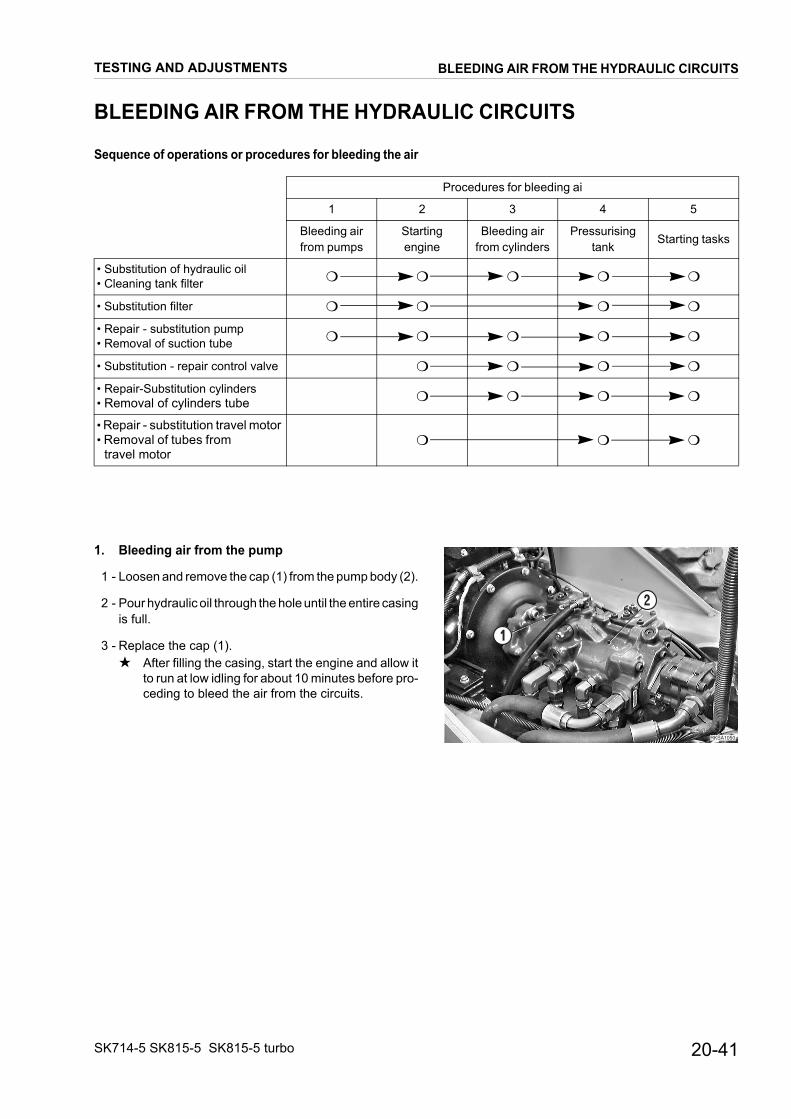
20-41SK714-5 SK815-5 SK815-5 turbo
BLEEDING AIR FROM THE HYDRAULIC CIRCUITS
Sequence of operations or procedures for bleeding the air
1. Bleeding air from the pump
1 - Loosen and remove the cap (1) from the pump body (2).
2 - Pour hydraulic oil through the hole until the entire casingis full.
3 - Replace the cap (1).★ After filling the casing, start the engine and allow it
to run at low idling for about 10 minutes before pro-ceding to bleed the air from the circuits.
Procedures for bleeding ai
1 2 3 4 5
Bleeding airfrom pumps
Startingengine
Bleeding airfrom cylinders
Pressurisingtank
Starting tasks
• Substitution of hydraulic oil• Cleaning tank filter ❍ ❍ ❍ ❍ ❍
• Substitution filter ❍ ❍ ❍ ❍
• Repair - substitution pump• Removal of suction tube ❍ ❍ ❍ ❍ ❍
• Substitution - repair control valve ❍ ❍ ❍ ❍
• Repair-Substitution cylinders• Removal of cylinders tube ❍ ❍ ❍ ❍
• Repair - substitution travel motor • Removal of tubes from
travel motor❍ ❍ ❍
RKSA1050
1
2
TESTING AND ADJUSTMENTS BLEEDING AIR FROM THE HYDRAULIC CIRCUITS

20-42 SK714-5 SK815-5 SK815-5 turbo
2. Bleeding air from the cylinders
1 - Start the engine and let it run at low idling for about 5 mi-nutes.
2 - Lower and raise the boom 4-5 times.★ Lower and raise the piston of the boom up to about
100 mm of the end of its stroke.Every care must be taken to avoid pressurising thecircuits.
3 - Bring the engine up to high idling and repeat the ope-rations described in point 2. Return the engine to lowidling and pout the piston through its entire stroke until itreaches max. pressure in both directions.
4 - Repeat the operation (starting from point 2) for bucketcylinder.
3. Bleeding air from any optional equipment★ This method must be used for all the optional working
equipment, unless otherwise indicated.
1 - Each time an item of optional working equipment is in-stalled, operate the equipment repeatedly, with the en-gine at low idling, until all air has been completelyeliminated.
RKS01530
RKS01520
TESTING AND ADJUSTMENTS BLEEDING AIR FROM THE HYDRAULIC CIRCUITS

REMOVAL AND INSTALLATION
HOW TO READ THE MANUAL................................. 3PRECAUTIONS TO BE TAKEN WHILE WORKING. 4ENGINE HOODRemoval and installation ........................................... 5CABTinting........................................................................ 6Lowering .................................................................... 8BATTERYRemoval and installation ........................................... 9STARTING MOTORRemoval and installation ......................................... 10ALTERNATORRemoval and installation ......................................... 11MUFFLER (SK714-5 SK815-5)Removal and installation ......................................... 12MUFFLER (SK815-5 turbo)Removal and installation ......................................... 13TURBOCHARGER (SK815-5 turbo)Removal .................................................................. 14Installation ............................................................... 15AIR INTAKE FILTERRemoval and installation ......................................... 16VALVE COVER (SK714-5 SK815-5)Removal and installation ......................................... 17VALVE COVER (SK815-5 turbo)Removal .................................................................. 18Installation ............................................................... 19NOZZLE (SK714-5 SK815-5)Removal and installation ......................................... 20NOZZLE (SK815-5 turbo)Removal and installation ......................................... 21INJECTION PUMPRemoval .................................................................. 22Installation ............................................................... 25CYLINDER HEAD (SK714-5 SK815-5)Removal .................................................................. 26Installation ............................................................... 28CYLINDER HEAD (SK815-5 turbo)Removal .................................................................. 29Installation ............................................................... 31COOLANT LIQUID PUMPRemoval and installation ......................................... 32
RADIATOR GROUPRemoval ...................................................................33Installation ................................................................34FUEL TANKRemoval ...................................................................35Installation ................................................................36CABRemoval ...................................................................37Installation ................................................................39ENGINE-PUMP GROUPRemoval ...................................................................40Installation ................................................................43COMPLETE HYDRAULIC PUMPRemoval ...................................................................44Installation ................................................................46GEAR PUMPRemoval and installation ..........................................47ENGINE-PUMP COUPLINGRemoval and installation ..........................................48CONTROL VALVERemoval and installation ..........................................49PPC VALVESRemoval and installation ..........................................50HUB WHEELRemoval ...................................................................51Installation ................................................................52Dismantling...............................................................53Assembly..................................................................54FINAL DRIVERemoval ...................................................................55Installation ................................................................56RAISING CYLINDERRemoval and installation ..........................................57BUCKET CYLINDERRemoval ...................................................................58Installation ................................................................59WORK EQUIPMENT CYLINDERSDisassembly .............................................................60Assembly..................................................................62COMPLETE WORKING EQUIPMENTRemoval ...................................................................66Installation ................................................................67WORKING EQUIPMENT SUPPORT FRAMERemoval and installation ..........................................68
30-1SK714-5 SK815-5 SK815-5 turbo

PAGE INTENTIONALLYLEFT BLANK

HOW TO READ THE MANUAL
1. Removal and Installation of the groups
(1) The procedures and information needed to carry out the work of removing or Installing units or groups are given in the removal procedure. The sequence of operations is not repeated in the installation procedure.
(2) Information needed for installation is marked with the symbol ; The same symbol is repeated at the end of each removal procedure for the same item, to indicate to which installation item it refers.
(Example)REMOVAL GROUP ● ● ● : .......................................................Title of operation
: ............................................................................................Safety precautions to be followed when carrying out the operation.
1 - Remove XXXX (1): ..............................................................Step in removal procedure.★ :.........................................................................................Technique or important point to remember when
removing XXXX (1)2 - ▲ ▲ ▲ (2):................................................................... This sign means that information is given
for the installation procedure3 - Remove ■ ■ ■ (3):
........... �: ......................................................................Recovery of oil or water, and the quantity to be recovered.
INSTALLATION GROUP ● ● ● : ...............................................Title of operation
• To install, reverse removal procedure.
: .........................................................................................Technique to be used for installation
★ :.........................................................................................Technique or important point to remember when removing ▲ ▲ ▲ (2)
• Addition of water or oil: ........................................................Step in removal procedure
★ :.........................................................................................Point to remember when adding water or oil.
2. To the precautions to be taken during the removal or installation of the groups, must be added the specific «PRE-CAUTIONS TO BE TAKEN DURING THE OPERATIONS». Always make sure that these precautions are taken.
3. List of special tools
(1) For details of the descriptions, codes and quantities of each tool (A1; A2 etc.) mentioned in the operational pro-cedures, see the list «SPECIAL TOOLS» supplied in this section.
4. List of the tightening torques and weights, and the quantities oil, liquids or grease needed to fill tanks and containers
(1) In the operating procedures, you will find the symbols , , , ; In the following order, these rep-resent the values of «TIGHTENING TORQUES», «WEIGHT OF PARTS OR GROUPS», «QUANTITIES OF OIL OR LIQUIDS TO BE INTRODUCED», «SCREW LOCKING MATERIAL, SEALANTS AND LUBRICA-TION», «LUBRICATING GREASE».
NOTE If no symbol is indicated, the values to be used are those given in the introductory sections of this manual.
1
1
1
REMOVAL AND INSTALLATION
SK714-5 SK815-5 SK815-5 turbo
HOW TO READ THE MANUAL
30-3

PRECAUTIONS TO BE TAKEN WHILE WORKING
★ When dismantling or installing a part, always take the following general precautions.
1. Precautions for removal operations• If not otherwise indicated, lower the work equipment until it rests on the ground.• If the coolant liquid contains an anti-freeze substance, follow the instructions given for drainage.• After having removed flanges and tubes, insert plugs to prevent impurities from entering.• Before removing a cylinder, fully retract the piston and tie it with wire.• Use a sufficiently large container to collect the oil.• Before removing a part from the machine, check the alignment reference marks which show the correct in-
stallation position. If necessary add further marks to avoid incorrect installation.• While dismantling the connectors, always grasp them firmly to avoid undue strain on the wiring.• If necessary, attach markers to the wires and tubes to avoid muddling them up during installation.• Check the number and height of the adjustments to a given clearance and store them in a safe place.• When raising the machine or some parts of it, use adequate equipment for the weight of the part concerned.• When using screws or eyebolts to remove items of the machinery, screw them alternately, and as deeply as
they will go.• Before removing a piece, clean the surrounding area and, after removal, cover the area to prevent dirt or dust
from gaining entrance.
2. Precautions to be taken during installation• Tighten nuts and screws with the specified tightening torques.• Install the flexible hoses, taking care not to entangle or twist them.• Bend the cotter pins and stops in such a way as to secure them.• When coating the threads with adhesives, clean the piece to remove oil and grease, then apply just enough ad-
hesive to cover the threading in a uniform manner.• When applying a liquid sealant, clean the surface involved, remove residual oil and grease, check that there are
no dents or dirt, then apply the liquid sealant in a uniform manner.• Clean all the parts, remove dirt, rust, burrs, or dents.• Apply a film of engine oil over all the moving parts.• Apply a film of anti-friction grease (Lithium EP MS2 NLGI 2) over all surfaces assembled with pressure, to avoid
sticking• After having mounted the snap-rings, check that they are firmly positioned in their seatings.• When installing electrical system jacks, remove any oil, dust or water that may have penetrated into them, then
connect them firmly.• If using eyebolts, check that they are not distorted, screw them in fully, and then align the eye with the hoisting
hook.• Mount the flanges in a uniform manner, and tighten the screws in criss-cross sequence, to avoid excessive pull
on one side only.
3. Precautions to be taken on completion of removal and installation operations.• If the coolant liquid has been drained away, close the drainage plug and add new liquid up to normal level. Start
the engine to circulate the liquid throughout the cooling system and then top up the level once more.• When the hydraulic equipment has been dismantled, add engine oil to the indicated level. Start up the engine
to circulate the oil in the hydraulic circuits, and then top up to the indicated level.• If hoses or hydraulic equipment, such as hydraulic cylinders, pumps, motors, solenoid valves and valves, are
removed for repairs or substitution, bleed air from the hydraulic circuits after having re-assembled the machine.★ For details, see «20. TESTING AND ADJUSTMENTS».• After having re-assembled cylinder joints or cylinders, or work equipment articulations, lubricate thoroughly.
REMOVAL AND INSTALLATION
30-4
PRECAUTIONS TO BE TAKEN WHILE WORKING
SK714-5 SK815-5 SK815-5 turbo

REMOVAL OF ENGINE HOOD
Completely lower the working equipment to the ground
RKSA1800
1
2
3
4
5
1
and stop the engine. 1 - Remove the retainer screws (1) from hinges (2) and (3).
2 - While keeping the hood lifted, remove the retainer nut (4) from the shock absorber (5).
Engine hood: 15 kg
INSTALLATION OF ENGINE HOOD• To replace, reverse removal procedure.
★ Check the centre and the lock engagement adjust-ment.
1
1
REMOVAL AND INSTALLATION
SK714-5 SK815-5 SK815-5 turbo
ENGINE HOOD
30-5

TILTING THE CAB
1 - Completely raise the working equipment and secure
RKSA0240
1
2
RKSA1500
3
4
��������
�
RKSA0261
6
8
9
6
7
10
them in their safety positions.
2 - Loosen the four screws (1) and remove the foot-rest (2).
★ Only if the engine or the complete pump are to be re-moved.
3 - Remove the engine hood. (For details see “REMOVAL OF THE ENGINE HOOD”).
With front door 4 - Loose screws (3), remove the bracket (4) and close the
front door.
5 - Loosen the screws (5) (two to each side) and raise the cab as far as the safety cables allow.
6 - Insert the safety pin.
★ If the engine or pump are to be removed, proceed as follows.
7 - Disconnect the four pipes (6) on the RH side, the two servo-control supply-pipes (7), and the four pipes (8) on the LH side.★ To disconnect the pipes, remove the retainer (9),
push the pipe (6) completely inside the union (10) and extract the pipe (6).
★ Mark the tubes to avoid exchanging them during re-assembly.
1
2
REMOVAL AND INSTALLATION
30-6
CAB
SK714-5 SK815-5 SK815-5 turbo
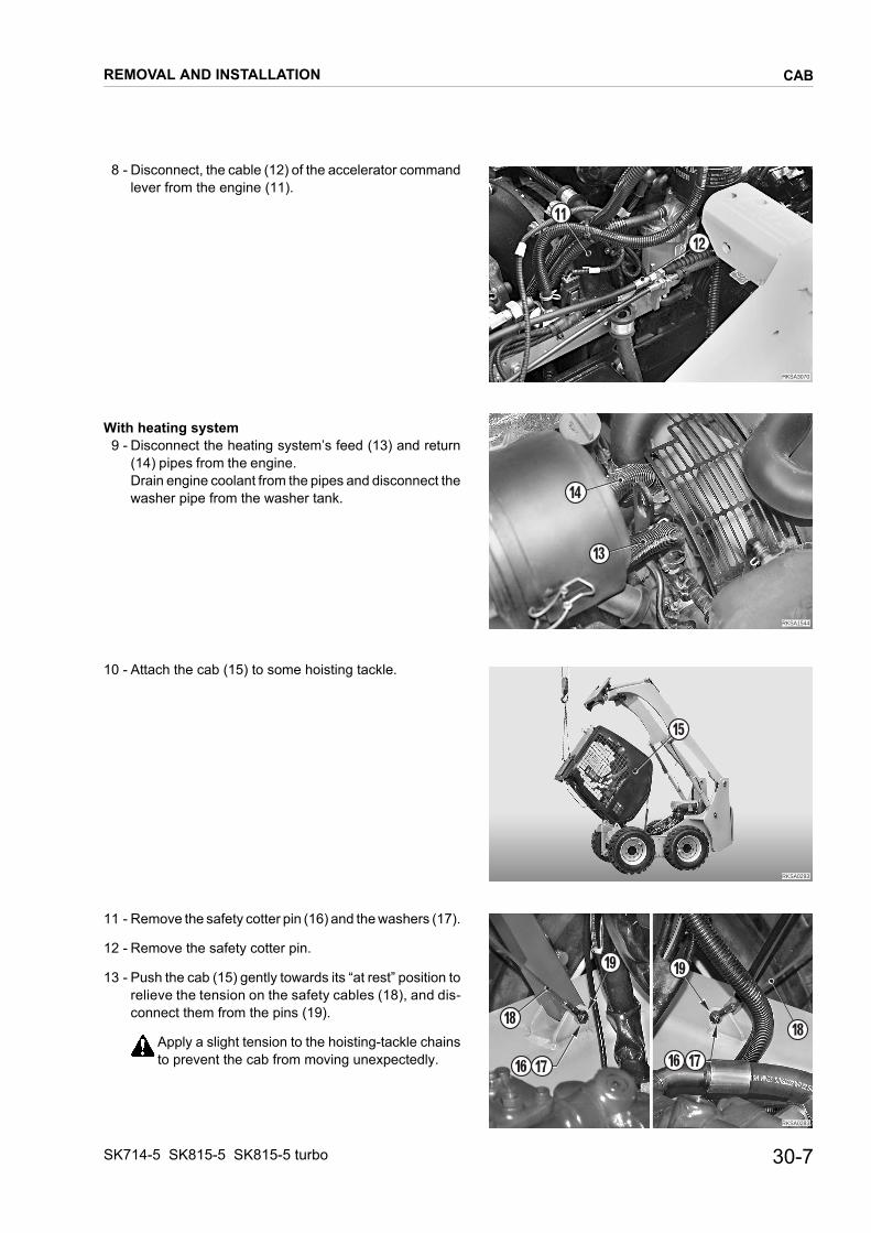
8 - Disconnect, the cable (12) of the accelerator command
��������
��
��
RKSA1544
13
14
RKSA0293
15
RKSA0283
16 17
18
19
16 17
18
19
lever from the engine (11).
With heating system 9 - Disconnect the heating system’s feed (13) and return
(14) pipes from the engine. Drain engine coolant from the pipes and disconnect the washer pipe from the washer tank.
10 - Attach the cab (15) to some hoisting tackle.
11 - Remove the safety cotter pin (16) and the washers (17).
12 - Remove the safety cotter pin.
13 - Push the cab (15) gently towards its “at rest” position to relieve the tension on the safety cables (18), and dis-connect them from the pins (19).
Apply a slight tension to the hoisting-tackle chains to prevent the cab from moving unexpectedly.
REMOVAL AND INSTALLATION
SK714-5 SK815-5 SK815-5 turbo
CAB
30-7

14 - Tilt the cab (15) slowly until the distance between the
RKSA0294
15
20
RKSA0300
A
centres of the dumper fixing hooks (20) is 1100 mm.★ The distance of 1100 mm corresponds to the max-
imum stretch of the dumper hooks.
15 - Remove the pins (19) of the dumper fixing hooks (20).
16 - Position a stand “A”, about 1200 mm high, and tilt the cab (15) until it is resting on the stand.★ Make sure that the connecting cables between the
cab and the engine are not being strained.
LOWERING THE CAB• To lower the cab back into position, reverse the tilting
procedure.
Screws: 110 Nm
• Connect the pipes by pushing them fully home in their seatings. Check correct connection by trying to extract them.
• Adjust the stroke of the accelerator lever cable. (For details, see «20. TESTING AND ADJUST-MENTS»).
1 - Fill up the cooling circuit.
2 - Start the engine to circulate the liquid through all cir-cuits.
3 - Stop the engine and check the level.
1
2
3
REMOVAL AND INSTALLATION
30-8
CAB
SK714-5 SK815-5 SK815-5 turbo

REMOVAL OF THE BATTERY
1 - Disconnect the negative cable (--) (1) and the positive
�������
��
�
�������
��
�
��������
�
cable (+) (2) from the battery (3) in that sequence.
2 - Loosen the nuts (4) that secure the battery clamp (5) a release the tie-rods (6) of the battery support.
3 - Tilt the battery clamp (5) towards the front of the ma-chine and lift out the battery.
INSTALLATION OF THE BATTERY• To replace, reverse removal procedure.
REMOVAL AND INSTALLATION
SK714-5 SK815-5 SK815-5 turbo
BATTERY
30-9
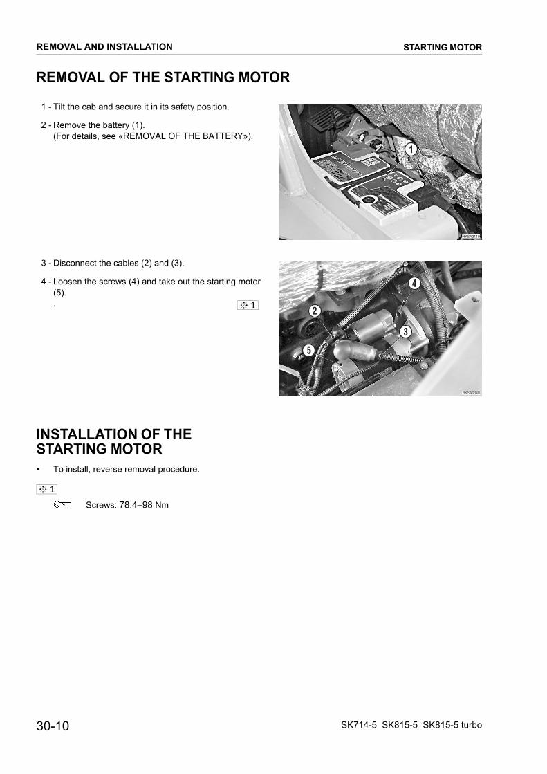
REMOVAL OF THE STARTING MOTOR
1 - Tilt the cab and secure it in its safety position.
��������
�
RKSA0340
5
2
3
4
2 - Remove the battery (1). (For details, see «REMOVAL OF THE BATTERY»).
3 - Disconnect the cables (2) and (3).
4 - Loosen the screws (4) and take out the starting motor (5). .
INSTALLATION OF THE STARTING MOTOR• To install, reverse removal procedure.
Screws: 78.4–98 Nm
1
1
REMOVAL AND INSTALLATION
30-10
STARTING MOTOR
SK714-5 SK815-5 SK815-5 turbo
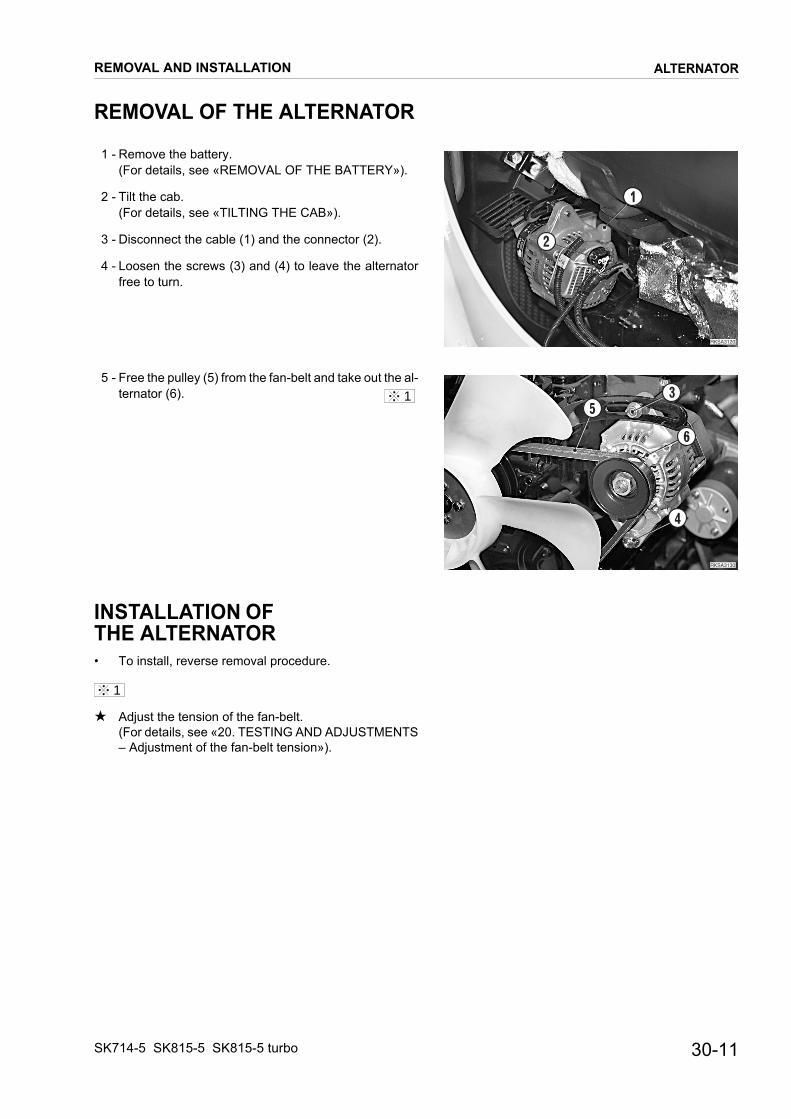
REMOVAL OF THE ALTERNATOR
1 - Remove the battery.
��������
�
�
��������
�
�
�
�
(For details, see «REMOVAL OF THE BATTERY»).
2 - Tilt the cab. (For details, see «TILTING THE CAB»).
3 - Disconnect the cable (1) and the connector (2).
4 - Loosen the screws (3) and (4) to leave the alternator free to turn.
5 - Free the pulley (5) from the fan-belt and take out the al-ternator (6).
INSTALLATION OF THE ALTERNATOR• To install, reverse removal procedure.
★ Adjust the tension of the fan-belt. (For details, see «20. TESTING AND ADJUSTMENTS – Adjustment of the fan-belt tension»).
1
1
REMOVAL AND INSTALLATION
SK714-5 SK815-5 SK815-5 turbo
ALTERNATOR
30-11
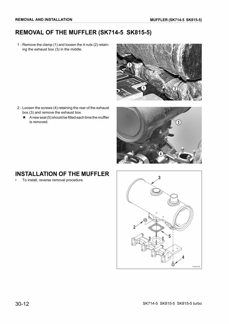
REMOVAL OF THE MUFFLER (SK714-5 SK815-5)
1 - Remove the clamp (1) and loosen the 4 nuts (2) retain-
��������
�
�
�
RKS03750
5
2
3
4
�������
�
�
ing the exhaust box (3) in the middle.
2 - Loosen the screws (4) retaining the rear of the exhaustbox (3) and remove the exhaust box.★ A new seal (5) should be fitted each time the muffler
is removed.
INSTALLATION OF THE MUFFLER• To install, reverse removal procedure.
REMOVAL AND INSTALLATION
30-12
MUFFLER (SK714-5 SK815-5)
SK714-5 SK815-5 SK815-5 turbo

MUFFLER (SK815-5 turbo)
REMOVAL OF THE MUFFLER (SK815-5 turbo)
1 - Loosen the screws (1) of protection (2) and remove it.
RKSA2490
1
1
2
RKSA2500
4
3
RKSA2510
5
64
5
7
RKSA2330
4
8
7
9
4
2 - Loosen and remove the screws (3) fixing the muffler (4).
3 - Mark the position of bracket (5). Remove the four nuts (6) fixing the muffler (4) to the tur-bocharger (7).
4 - Loose the screws (8).
5 - Remove the muffler (4).★ A new seal (9) should be fitted each time the muffler
is removed.
INSTALLATION OF THE MUFFLER• To install, reverse removal procedure.
REMOVAL AND INSTALLATION
30-13SK714-5 SK815-5 SK815-5 turbo
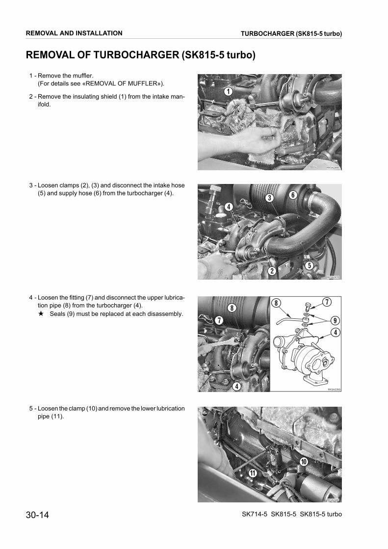
TURBOCHARGER (SK815-5 turbo)
REMOVAL OF TURBOCHARGER (SK815-5 turbo)
1 - Remove the muffler.
RKSA2460
1
RKSA2470
3 6
25
4
RKSA2350
97
8
4
8 7
4
RKSA2480
10
11
(For details see «REMOVAL OF MUFFLER»).
2 - Remove the insulating shield (1) from the intake man-ifold.
3 - Loosen clamps (2), (3) and disconnect the intake hose (5) and supply hose (6) from the turbocharger (4).
4 - Loosen the fitting (7) and disconnect the upper lubrica-tion pipe (8) from the turbocharger (4).★ Seals (9) must be replaced at each disassembly.
5 - Loosen the clamp (10) and remove the lower lubrication pipe (11).
REMOVAL AND INSTALLATION
30-14 SK714-5 SK815-5 SK815-5 turbo
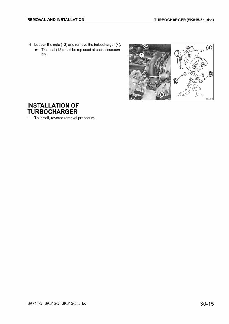
TURBOCHARGER (SK815-5 turbo)
6 - Loosen the nuts (12) and remove the turbocharger (4).
RKSA2340
4
12
13
12
4
★ The seal (13) must be replaced at each disassem-bly.
INSTALLATION OF TURBOCHARGER• To install, reverse removal procedure.
REMOVAL AND INSTALLATION
30-15SK714-5 SK815-5 SK815-5 turbo

AIR INTAKE FILTER
REMOVAL OF THE AIR INTAKE FILTER
Disconnect the battery’s negative end cable (–).SK714-5 SK815-5
�������
�
�
�
��������
�
�
�
��������
�
�
��
�������
��
�
�
SK815-5 turbo
SK714-5 SK815-5
SK815-5 turbo
1 - Disconnect the connector (2) and hose (3) from the washer tank (1).
2 - Remove the washer tank (1).
3 - Loosen the clamp (4) and disconnect the connector (5) from the air filter clogging sensor.
4 - Loosen the screws (6) and remove the complete air filter (7).
INSTALLATION OF AIR INTAKE FILTER• To install, reverse removal procedure.
REMOVAL AND INSTALLATION
30-16 SK714-5 SK815-5 SK815-5 turbo

REMOVAL AND INSTALLATION VALVE COVER (SK714-5 SK815-5)
REMOVAL OF THE VALVE COVER (SK714-5 SK815-5)
Disconnect the negative terminal cable (–) from the bat-
�������
�
��������
�
�
�
�
�
�
��������
�
tery.
1 - Remove the air filter (1). (For detail see «REMOVAL OF THE AIR FILTER»).
2 - Loosen the 3 screws (2) and remove the valve cover (3).
INSTALLATION OF THE VALVE COVER• To install, reverse the removal procedure.
★ Check the state of the seal (4) on the valve cover (3), and of the O-rings (5); thoroughly clean the contact surface on the cylinder head.
Screw: 22.6–28.4 Nm
1
1
30-17SK714-5 SK815-5 SK815-5 turbo

VALVE COVER (SK815-5 turbo)
REMOVAL OF THE VALVE COVER (SK815-5 turbo)
Disconnect the negative terminal cable (–) from the bat-
��������
�
��������
�
�
�
�
��������
�
��
�
������ �
�
�
�
�
tery.
1 - Remove the air filter (1). (For detail see «REMOVAL OF THE AIR FILTER»).
2 - Loosen the screws (2) and remove the clamp (3).
3 - Remove the high-pressure pipes (4).
4 - Loosen the two screws (5) (n° 3), remove the four cen-tering bushings (6) and the valve cover (7).
1
2
REMOVAL AND INSTALLATION
30-18 SK714-5 SK815-5 SK815-5 turbo

VALVE COVER (SK815-5 turbo)
INSTALLATION OF THE VALVE COVER
• To install, reverse the removal procedure.
��������
�
�
�
High-pressure pipe union: 29.4–34.3 Nm★ Check the state of the seal (8) on the valve cover(7), and of the O-rings (9); thoroughly clean thecontact surface on the cylinder head.
Screw: 22.6–28.4 Nm
1
2
REMOVAL AND INSTALLATION
30-19SK714-5 SK815-5 SK815-5 turbo

NOZZLE (SK714-5 SK815-5)
REMOVAL OF THE NOZZLE (SK714-5 SK815-5)
1 - Remove the air filter (1).
�������
�
��������
�
�
��������
�
��
(For detail see «REMOVAL OF THE AIR FILTER»).
2 - Remove the high-pressure pipes (2) and the fuel return tubes (3).
3 - Loosen screws (4) and remove clips (5).
4 - Remove the complete injection nozzles (6).
INSTALLATION OF THE NOZZLE HOLDER• To install, reverse the removal procedure.
High-pressure pipe union: 29.4–34.3 Nm
Screws: 22.6–28.4 Nm
1
2
1
2
REMOVAL AND INSTALLATION
30-20 SK714-5 SK815-5 SK815-5 turbo

NOZZLE (SK815-5 turbo)
REMOVAL OF THE NOZZLE (SK815-5 turbo)
1 - Remove the air filter (1).
RKSA1680
2
1
31
2
�������
��
���
(For detail see «REMOVAL OF THE AIR FILTER»).
2 - Remove the valve cover (1). (For detail see «REMOVAL OF THE VALVE COVER»).
3 - Loosen the five screws (1) and remove the fuel pipe (2)..★ take care to not damage the five gasket (3).
4 - Loosen the screws (4) and remove the four bracket (5).
5 - Remove the nozzle (6).
INSTALLATION OF THE NOZZLE• To install, reverse the removal procedure.
Screw: 9.8–11.8 Nm
Screws: 22.6–28.4 Nm
1
2
1
2
REMOVAL AND INSTALLATION
30-21SK714-5 SK815-5 SK815-5 turbo

INJECTION PUMP
REMOVAL OF INJECTION PUMP
1 - Disconnect the negative terminal cable (–) from the
��������
�
�
�������
�
�������
�
������ �
�
SK714-5 SK815-5
SK815-5 turbo
battery.
2 - Close the cock of separator to prevent fuel leakage.
1 - Remove radiator group. (For details, see «REMOVAL OF THE RADIATOR»).
2 - Disconnect connector (1) and accelerator cable (2).
3 - Remove the air filter (3). (For details, see «REMOVAL OF AIR FILTER»).
4 - Disconnect the oil dipstick from the cylinder head (4).
1
REMOVAL AND INSTALLATION
30-22 SK714-5 SK815-5 SK815-5 turbo

INJECTION PUMP
5 - Disconnect from injection pump (5) fuel feeding pipes
��������
�
�
����
�
��
��������
��
��������
����
��������
��
(6), return pipes (7), feedback pipe (8) and the coolant pipes (9) and (10).
6 - Disconnect high pressure pipes (11) from injection pump (5).
7 - Disconnect injection pump (5) lubricating pipe (12).
8 - Remove fan (13) and cover (14)
9 - Loosen and remove nut (15) and lock washer (16) of pump driving gear.
★ Be careful not let nut (15) and lock washer drop in the housing.
2
3
4
REMOVAL AND INSTALLATION
30-23SK714-5 SK815-5 SK815-5 turbo

INJECTION PUMP
10 - Remove pump (5) driving gear (16).
���������
��
���
��
�
��
��������
����
�
�
★ Before removing pump driving gear, mark position compared to idling gear.
★ For removal, use a puller (X1) and tighten its screws (X2) directly in the gear (16).
★ During removal be careful not let key drop (17) in the housing.
11 - Loosen nuts (18) (No. 4).
12 - Loosen screws (19) (No. 3) and remove injection pump (5) with O-rings (20).
5
6
REMOVAL AND INSTALLATION
30-24 SK714-5 SK815-5 SK815-5 turbo

INJECTION PUMP
INSTALLATION OF INJECTION PUMP
• To install, reverse the removal procedure.
★ Check accelerator stroke lever. (For details, see «20. CONTROLS AND ADJUST-MENTS»).
High pressure pipe: 29.4–34.3 Nm
Cover surface: liquid gasket
Screw: 9.8–11.8 Nm
★ Align marks among gears before to install pump and nut.
Nut: 78–88 Nm
Pump lock nuts: 22.6–28.4 Nm
★ Check fuel injection timing. (For details, see «20. CONTROLS AND ADJUST-MENTS»).
Screw: 22.6–28.4 Nm
1
2
3
4
5
6
REMOVAL AND INSTALLATION
30-25SK714-5 SK815-5 SK815-5 turbo
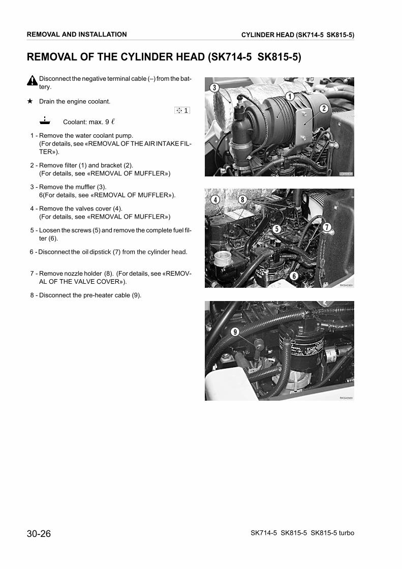
CYLINDER HEAD (SK714-5 SK815-5)
REMOVAL OF THE CYLINDER HEAD (SK714-5 SK815-5)
Disconnect the negative terminal cable (–) from the bat-
��������
��������
��
�
��
��������
�
�
�
tery.★ Drain the engine coolant.
Coolant: max. 9 �
1 - Remove the water coolant pump. (For details, see «REMOVAL OF THE AIR INTAKE FIL-TER»).
2 - Remove filter (1) and bracket (2). (For details, see «REMOVAL OF MUFFLER»)
3 - Remove the muffler (3). 6(For details, see «REMOVAL OF MUFFLER»).
4 - Remove the valves cover (4). (For details, see «REMOVAL OF MUFFLER»)
5 - Loosen the screws (5) and remove the complete fuel fil-ter (6).
6 - Disconnect the oil dipstick (7) from the cylinder head.
7 - Remove nozzle holder (8). (For details, see «REMOV-AL OF THE VALVE COVER»).
8 - Disconnect the pre-heater cable (9).
1
REMOVAL AND INSTALLATION
30-26 SK714-5 SK815-5 SK815-5 turbo

CYLINDER HEAD (SK714-5 SK815-5)
9 - Remove the rocker-arm shaft (10). 2
����������
��
�������
��
�� ��
RKS01630
1
3
7
5
9
11
1618
1713
1412
1015
64
2
8Lat
o v
ola
no
Lato aspirazione
Lato scarico
★ Loosen the lock nuts and unscrew the valve tap-pets by 2-3 turns.
10 - Take out the rocker-arm control rods (11).
11 - Take out the screws (12) in the sequence indicated and remove the complete cylinder head (13).
★ The cylinder head gasket (14) must be substituted every time it is dismantled.
3
4
REMOVAL AND INSTALLATION
30-27SK714-5 SK815-5 SK815-5 turbo

CYLINDER HEAD (SK714-5 SK815-5)
INSTALLATION OF THE CYLINDER HEAD (SK714-5 SK815-5)
• To install, reverse the removal procedure.
RKS01641
Fly
wh
eel s
ide
Intake side
Exhaust side
1812
10
1416
1315
1711
8
31
26
57
94
1 - Fill up the cooling circuit.
Coolant: approx. 9 �
2 - Start the engine to circulate the liquid through all cir-cuits. Stop the engine and check the level.
3 - Pressurize the hydraulic tank and bleed air from the hy-draulic circuits. (For details, see «20. CONTROLS AND ADJUST-MENTS»).
Screw: 22.6–28.4 Nm
★ Adjust valve clearance. (For details, see «20. CON-TROLS AND ADJUSTMENTS - Adjusting valve clear-ance»).
★ Raise the cylinder head, keeping it horizontal, and place it on the gasket without shifting anything.
★ Lubricate the screw-threadings with engine oil.
★ Tighten the screws in two steps in the sequence given. (See illustration on the right).
First step: Screw: 41.1–46.9 Nm
Second step: Screw: 85.3–91.1 Nm
1
2
3
4
REMOVAL AND INSTALLATION
30-28 SK714-5 SK815-5 SK815-5 turbo

CYLINDER HEAD (SK815-5 turbo)
REMOVAL OF THE CYLINDER HEAD (SK815-5 turbo)
Disconnect the negative terminal cable (–) from the bat-
��������
�
�
�
�������
�
�
�
�
�������
��
����� ��
tery.
★ Drain the engine coolant.
Coolant: max.9 �
1 - Remove the water coolant pump. (For details, see «REMOVAL OF WATER COOLANT PUMP»).
2 - Remove the air filter (1) and the bracket (2). (For details, see «REMOVAL OF AIR FILTER»).
3 - Remove the muffler (2). (For details, see «REMOVAL OF MUFFLER»).
4 - Loosen the screws (4) and remove the complete fuel fil-ter (5).
5 - Remove the valve cover (6).
6 - Disconnect the oil dipstick (7) from the cylinder head (7).
7 - Remove the nozzle (8). (For details, see «REMOVAL OF NOZZLES»).
8 - Disconnect the pre-heater cable (9).
1
REMOVAL AND INSTALLATION
30-29SK714-5 SK815-5 SK815-5 turbo

CYLINDER HEAD (SK815-5 turbo)
9 - Remove the rocker-arm shaft (10). 2
�������
���
��
��
��
�������
RKS01631
1
3
7
5
9
11
1618
1713
1412
1015
64
2
8Fly
wh
eel s
ide
Intake side
Exhaust side
★ Loosen the lock nuts and unscrew the valve tap-pets by 2-3 turns.
10 - Take out the rocker-arm control rods (11).
11 - Take out the screws (12) in the sequence indicated and remove the complete cylinder head (13).★ The cylinder head gasket (14) must be substituted
every time it is dismantled.
3
4
REMOVAL AND INSTALLATION
30-30 SK714-5 SK815-5 SK815-5 turbo

CYLINDER HEAD (SK815-5 turbo)
INSTALLATION OF THE CYLINDER HEAD (SK815-5 turbo)
• To install, reverse the removal procedure.
RKS01641
Fly
wh
eel s
ide
Intake side
Exhaust side
1812
10
1416
1315
1711
8
31
26
57
94
1 - Fill up the cooling circuit.
Coolant: approx. 9 �
2- Start the engine to circulate the liquid through all cir-cuits. Stop the engine and check the level.
3 - Pressurize the hydraulic tank and bleed air from the hy-draulic circuits. (For details, see «20. CONTROLS AND ADJUST-MENTS»).
Screw: 22.6–28.4 Nm
★ Adjust valve clearance. (For details, see «20. CON-TROLS AND ADJUSTMENTS - Adjusting valve clear-ance»).
★ Raise the cylinder head, keeping it horizontal, and place it on the gasket without shifting anything.
★ Lubricate the screw-threads with engine oil.
★ Tighten the screws in two steps in the sequence given. (See illustration on the right).
First step: Screw: 41.1–46.9 Nm
Second step: Screw: 85.3–91.1 Nm
1
2
3
4
REMOVAL AND INSTALLATION
30-31SK714-5 SK815-5 SK815-5 turbo

COOLANT LIQUID PUMP
REMOVAL OF THE COOLANT LIQUID PUMP
Disconnect the cable from the negative (–) battery
����� ��
�
RKS01850
2
3
4
RKS01840
5
6
8
7
terminal.
★ Drain the engine coolant liquid.
Engine coolant liquid: max. 9 �
1 - Remove the radiator group (1). (For details, see «RE-MOVAL OF THE RADIATOR GROUP»).
2 - Loosen the screws (2), remove the fan (3) and the spac-er (4). Loosen the alternator drive belt and disengage the cir-culation pump pulley.
3 - Loosen the screws (5) and remove the complete pump (6), the seal (7), and the O-ring (8).
INSTALLATION OF THE COOLANT LIQUID PUMP• To install, reverse removal procedure.
1 - Fill up the coolant liquid circuit.
2 - Start the engine to circulate the liquid and oil in all cir-cuits. Stop the engine and check the levels.
3 - Pressurise the tank and bleed the air from all circuits. (For details, see «20. TESTING AND ADJUST-MENTS»).
★ Adjust the belt tension. (For details, see «20. TESTING AND ADJUSTMENTS – Testing and adjustment of the fan-belt »).
Fan screws: 9.8–11.8 Nm
★ A new seal (7) and new O-ring (8) must be fitted each time the pump is removed.
Pump screws: 22.6–28.4 Nm
1
2
3
1
2
3
REMOVAL AND INSTALLATION
30-32 SK714-5 SK815-5 SK815-5 turbo

RADIATOR GROUP
REMOVAL OF THE RADIATOR GROUP
Completely raise the working equipment and tilt the cab.
RKSA0460
1
2
3
RKSA0470
45
6
7
RKSA0480
8
9
10
9
RKSA0490
11
12
(For details, see «TILTING THE CAB»).
★ Drain the hydraulic oil.
Hydraulic oil: max. 39 �
★ Drain the coolant liquid:
Coolant liquid: max. 9 �
1 - Disconnect the hose (2) from the pump (1).
2 - Disconnect the coolant liquid drainage pipe (3) from the radiator.
3 - Disconnect the cable (4) of the hydraulic-oil clogging-sensor filter.
4 - Loosen the clamp (5) and disconnect the coolant liquid delivery pipe (6).
5 - Disconnect the coolant liquid return pipe (7)
6 - Attach the radiator group (8) to some hoisting tackle and apply a slight tension to the cables.
Radiator-oil cooler group: 62 kg
7 - Loosen the screws (9), raise the radiator group (8) until the lower supports can be released, and move it a little way away from the frame.
8 - Disconnect the reversing siren connector (10).
9 - Disconnect the pipes (11) and (12) and remove the complete group (8).
1
2
REMOVAL AND INSTALLATION
30-33SK714-5 SK815-5 SK815-5 turbo
RADIATOR GROUP
INSTALLATION OF THE RADIATOR GROUP
• To install, reverse removal procedure.
1 - Fill up the hydraulic oil to maximum level.
Hydraulic oil: approx. 27 �
2 - Fill up the coolant liquid circuit to maximum level.
Coolant liquid: approx. 9 �
3 - Start the engine to circulate the oil and the coolant, and check that there are no leaks.
4 - Stop the engine, check the levels and, if necessary, top them up.
Screws: 190 Nm
5 - Pressurise the tank and bleed the air from all circuits. (For details, see «20. TESTING AND ADJUST-MENTS»).
1
2
REMOVAL AND INSTALLATION
30-34 SK714-5 SK815-5 SK815-5 turbo
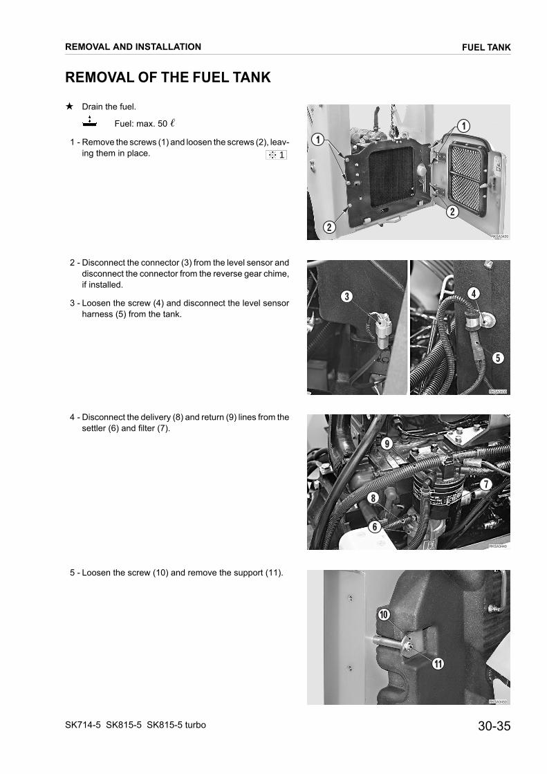
FUEL TANK
REMOVAL OF THE FUEL TANK
★ Drain the fuel.
����� ��
�
�
�
�
����� ��
�
�
�
����� �
�
�
�
����� ��
�
��
Fuel: max. 50 �
1 - Remove the screws (1) and loosen the screws (2), leav-ing them in place.
2 - Disconnect the connector (3) from the level sensor and disconnect the connector from the reverse gear chime, if installed.
3 - Loosen the screw (4) and disconnect the level sensor harness (5) from the tank.
4 - Disconnect the delivery (8) and return (9) lines from the settler (6) and filter (7).
5 - Loosen the screw (10) and remove the support (11).
1
REMOVAL AND INSTALLATION
30-35SK714-5 SK815-5 SK815-5 turbo
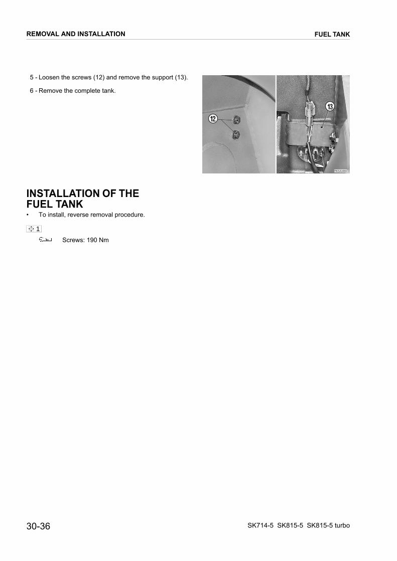
FUEL TANK
5 - Loosen the screws (12) and remove the support (13).
����� ��
��
��
6 - Remove the complete tank.
INSTALLATION OF THE FUEL TANK• To install, reverse removal procedure.
Screws: 190 Nm
1
REMOVAL AND INSTALLATION
30-36 SK714-5 SK815-5 SK815-5 turbo

CAB
REMOVAL OF THE CAB
1 - Remove the complete working equipment.
RKSA0520
1
2
1
1 1
RKSA0530
3
4
5
RKSA0540
5 67
8
RKSA0550
5
6
9
10
(For details, see «REMOVAL OF THE WORKING EQUIPMENT»).
2 - Loosen the nuts (1) and tilt the rear panel (2) towards the front of the machine.
3 - Disconnect the connectors (3) from the cab cabling (4) and release the engine cabling (5) from its retaining clamps.
4 - Tilt the cab. (For details, see «TILTING THE CAB»).
5 - Disconnect the four pipes (6) on the RH side, the two servo-control feed-pipes (7) and the four pipes (8) on the LH side.★ To disconnect the pipes, remove the retainer (9)
push the pipe (6) completely inside the union (10) and extract the pipe (6).
★ Mark the tubes to avoid exchanging them during re-assembly.
6 - Pull out the cab cabling (5).
1
REMOVAL AND INSTALLATION
30-37SK714-5 SK815-5 SK815-5 turbo

REMOVAL AND INSTALLATION CAB
With front door
RKSA1545
11
12
RKSA1901
13
14
����� ��
����
RKSA0272
17
7 - Disconnect the heating system’s supply (11) and return (12) hoses from the engine and drain any engine cool-ant from the hoses.★ Mark the hoses to avoid mixing them during instal-
lation.
8 - Disconnect the hose (14) from the washer tank (13).
9 - Disconnect the accelerator command lever cable (16) from the engine (15).
10 - Connect the cab (17) to some hoisting tackle.
2
30-38 SK714-5 SK815-5 SK815-5 turbo

REMOVAL AND INSTALLATION CAB
11 - Remove the safety cotter pins (18) and the washers
RKSA0284
222121
18
20
1918 19
20
RKSA0562
2423
25
17
RKSA1240
1
(19).
12 - Push the cab slightly towards its “at rest” position to re-lieve the strain on the safety cables (20), and disconnect the cables from the pins (21).
Apply a slight tension to the chains of the hoisting tackle to prevent the cab from swinging about un-expectedly.
13 - Tilt the cab (17) slowly until the distance between the centres of the dumper fixing hooks is 1100 mm.★ The distance of 1100 mm corresponds to the max-
imum stretch of the dumper hooks.
14 - Remove the pins (21) from the dumper fixing hooks (22).
15 - Loosen the nuts (23) and remove the screws (24) and washers (25).
16 - Remove the complete cab (17).
INSTALLATION OF THE CAB• To install, reverse removal procedure.
• Fill up the coolant liquid circuit to maximum level.• Start the engine to circulate the coolant and check
that there are no leaks.• Stop the engine, check the levels and, if necessary,
top them up.
• Mount the nuts (1) on the hoses and connect the pipes by pushing them fully home in their seatings. Check the correct connection by trying to extract them.
• Adjust the stroke of the accelerator lever cable. (For details, see «20. TESTING AND ADJUST-MENTS»).
1
2
30-39SK714-5 SK815-5 SK815-5 turbo
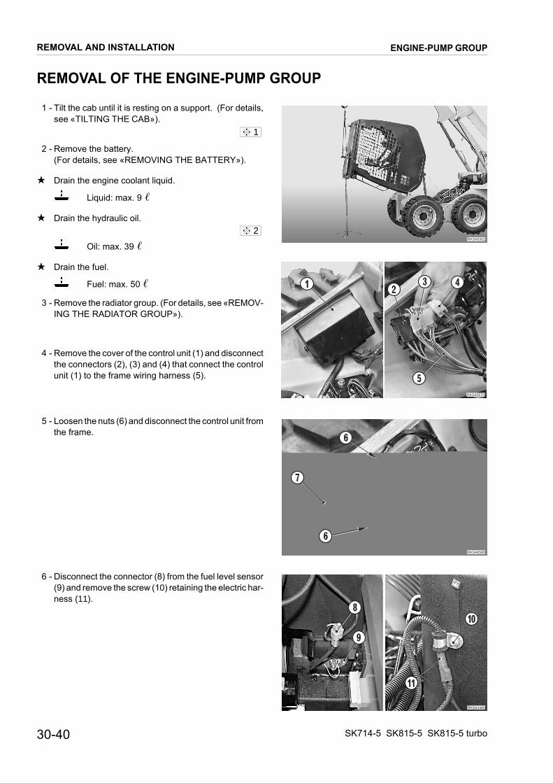
REMOVAL AND INSTALLATION ENGINE-PUMP GROUP
REMOVAL OF THE ENGINE-PUMP GROUP
1 - Tilt the cab until it is resting on a support. (For details,
RKSA0301
RKSA0570
12
3 4
5
RKSA0580
6
7
6
����� �
�
�
��
see «TILTING THE CAB»).
2 - Remove the battery. (For details, see «REMOVING THE BATTERY»).
★ Drain the engine coolant liquid.
Liquid: max. 9 �
★ Drain the hydraulic oil.
Oil: max. 39 �
★ Drain the fuel.
Fuel: max. 50 �
3 - Remove the radiator group. (For details, see «REMOV-ING THE RADIATOR GROUP»).
4 - Remove the cover of the control unit (1) and disconnect the connectors (2), (3) and (4) that connect the control unit (1) to the frame wiring harness (5).
5 - Loosen the nuts (6) and disconnect the control unit from the frame.
6 - Disconnect the connector (8) from the fuel level sensor (9) and remove the screw (10) retaining the electric har-ness (11).
1
2
30-40 SK714-5 SK815-5 SK815-5 turbo

REMOVAL AND INSTALLATION ENGINE-PUMP GROUP
7 - Disconnect the servo-control pressure sensor connec-
����� �
��
��
�� ��
��������
��
��
�
��
��������
��
�
����
��������
��
��
��
��
tors (12) and disconnect the support (13) from the en-gine (14).
8 - Disconnect the accelerator pedal cable (15) from the engine (14).
9 - Disconnect the delivery (18) and return (19) pipes from the prefilter (16) and the filter (17).
10 - Disconnect the pipes (21), (22) and (23) from the pump (20).★ Mark the tubes to avoid exchanging them during re-
assembly.
11 - Disconnect the pipes (24), (25), (26), and (27) from the pump.★ Mark the tubes to avoid exchanging them during re-
assembly.
30-41SK714-5 SK815-5 SK815-5 turbo

REMOVAL AND INSTALLATION ENGINE-PUMP GROUP
With front door
��������
�
��
������ �
�
12 - Disconnect the heating system’s supply (28) and return (29) hoses from the engine and drain any engine cool-ant from the hoses.
13 - Attach the engine-pump group to some hoisting tackle and apply a slight tension to the cables.
14 - Loosen the four nuts (30) that secure the engine and re-move the complete group.
Engine-pump group: 290 kg
3
30-42 SK714-5 SK815-5 SK815-5 turbo
REMOVAL AND INSTALLATION ENGINE-PUMP GROUP
INSTALLATION OF THE ENGINE-PUMP GROUP
• To install, reverse removal procedure.
1 - Fill the hydraulic oil tank up to maximum level.
While filling the tank, bleed the air from the pump. (For details, see «20. TESTING AND ADJUSTMENTS»).
Hydraulic oil: approx. 27 �
2 - Fill the coolant liquid circuit up to maximum level.
Coolant liquid: approx. 9 �
3 - Fill the fuel tank and bleed the air from the system. (For details, see «20. TESTING AND ADJUSTMENTS»).
Fuel: max. 50 �
4 - Start the engine to circulate the oil and coolant liquid and check that there are no leaks.
5 - Stop the engine, check the levels and, if necessary, top them up.
6 - Bleed the air from the hydraulic circuits and pressurise the tank. (For details, see «20. TESTING AND AD-JUSTMENTS»).
★ Adjust the stroke of the accelerator cables. (For details, see «20. TESTING AND ADJUST-MENTS»).
Engine nuts: 60–75 Nm
1
2
30-43SK714-5 SK815-5 SK815-5 turbo
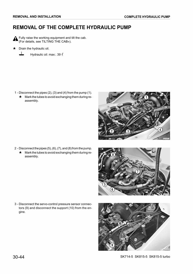
REMOVAL AND INSTALLATION COMPLETE HYDRAULIC PUMP
REMOVAL OF THE COMPLETE HYDRAULIC PUMP
Fully raise the working equipment and tilt the cab.
RKSA0611
1
2 3 4
RKSA0231
5
6
7
8
��������
�
��
(For details, see TILTING THE CAB»).
★ Drain the hydraulic oil.
Hydraulic oil: max:. 39 �
1 - Disconnect the pipes (2), (3) and (4) from the pump (1).★ Mark the tubes to avoid exchanging them during re-
assembly.
2 - Disconnect the pipes (5), (6), (7), and (8) from the pump.★ Mark the tubes to avoid exchanging them during re-
assembly.
3 - Disconnect the servo-control pressure sensor connec-tors (9) and disconnect the support (10) from the en-gine.
30-44 SK714-5 SK815-5 SK815-5 turbo
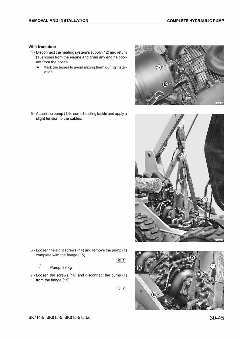
REMOVAL AND INSTALLATION COMPLETE HYDRAULIC PUMP
Whit front door
RKSA1547
13
12
RKSA0640
1
RKSA0651
1
14
15
16
4 - Disconnect the heating system’s supply (12) and return (13) hoses from the engine and drain any engine cool-ant from the hoses.★ Mark the hoses to avoid mixing them during instal-
lation.
5 - Attach the pump (1) to some hoisting tackle and apply a slight tension to the cables.
6 - Loosen the eight screws (14) and remove the pump (1) complete with the flange (15).
Pump: 88 kg
7 - Loosen the screws (16) and disconnect the pump (1) from the flange (15).
1
2
30-45SK714-5 SK815-5 SK815-5 turbo

REMOVAL AND INSTALLATION COMPLETE HYDRAULIC PUMP
INSTALLATION OF THE HYDRAULIC PUMP
• To install, reverse removal procedure.
Flange screws: 80 Nm
Flange screws: Loctite 262
Pump shaft: Lithium EP MS2 NLGI 2
Pump screws: 195 Nm
Pump screws: Loctite 262
1 - Fill the tank up to maximum level.
Hydraulic oil requirement: 27 � approx.
Bleed the air from the pump. (For details, see «20. TESTING AND ADJUST-MENTS»).
2 - Start the engine to circulate the oil and check that there are no leaks.
3 - Stop the engine, check the levels and, if necessary, top them up.
4 - Bleed the air from the hydraulic circuits and pressurise the tank. (For details, see «20. TESTING AND ADJUST-MENTS»).
1
2
30-46 SK714-5 SK815-5 SK815-5 turbo

REMOVAL AND INSTALLATION GEAR PUMP
REMOVAL OF THE GEAR PUMP
Fully raise the working equipment and tilt the cab.
RKSA0660
12
3
4
5
4 RKS01740
(For details, see «TILTING THE CAB»).
★ Drain the hydraulic oil
Hydraulic oil: max. 39 �
1 - Disconnect from the pump (1) the suction pipe (2) and the pipe (3) (one for the normal version, two for the HIGHFLOW version.
2 - Loosen the two screws (4) and remove the pump (1) complete with the O-ring (5).
INSTALLATION OF THE GEAR PUMP★ To install, reverse removal procedure.
Screws: 59–74 Nm
1
1
30-47SK714-5 SK815-5 SK815-5 turbo

REMOVAL AND INSTALLATION ENGINE-PUMP COUPLING
REMOVAL OF ENGINE-PUMP COUPLING
Fully raise the working equipment and tilt the cab.
RKSA0670
12
(For details, see «TILTING THE CAB»).
1 - Remove the pump. (For details, see «REMOVAL OF THE PUMP»).
2 - Take out the screws (1) and remove the coupling (2).
★ Replace screws (1) every dismantling.
INSTALLATION OF THE ENGINE-PUMP COUPLING• To install, reverse the removal procedure.
Coupling screws: 80 Nm
1
1
30-48 SK714-5 SK815-5 SK815-5 turbo

REMOVAL AND INSTALLATION CONTROL VALVE
REMOVAL OF THE CONTROL VALVE
Fully raise the working equipment and tilt the cab.
RKSA0680
1
2
3
2
41
RKS01880
(For details, see «TILTING THE CAB»).
Release residual pressures from all circuits and from the tank. (For details, see «20. TESTING AND AD-JUSTMENTS»).
★ Drain the hydraulic oil.
Hydraulic oil: max. 39 �
1 - Disconnect from the control valve (1) the servo-control pipes (2), the delivery pipes to the actuators, and the de-livery and return pipes (3).★ Mark the tubes to avoid exchanging them during re-
assembly.
2 - Loosen the three screws (4) and remove the control valve (1).
Control valve: max. 21.5 kg
INSTALLATION OF THE CONTROL VALVE★ To install, reverse removal procedure.
Control valve screws: 35 Nm
1 - Fill the hydraulic oil tank up to maximum level.
Hydraulic oil: max. 39 �
2 - Start the engine at low idling to circulate the oil through-out the system.
3 - Pressurise the tank and bleed the air from all circuits. (For details, see «20. TESTING AND ADJUST-MENTS»).
1
1
30-49SK714-5 SK815-5 SK815-5 turbo

REMOVAL OF PPC VALVES
Lower the working equipment until it is resting on the
RKSA0690
1
2
3
5
6
4
RKSA0700
7
8
9
10
RKSA0710
P1
P2
P3
P4
P T
L.H. PPC VALVE
RKSA0720
P1
P2
P3
P4
P T
R.H. PPC VALVE STANDARDR.H. AND L.H. PPC VALVES PATTERN CHANGE
ground, stop the engine and remove the ignition key.
Release residual pressures from all circuits and from the tank. (For details, see «20. TESTING AND AD-JUSTMENTS»).
With front door
1 - Remove the heater group. (For details, see «REMOVAL OF HEATER FAN» up to point 6).
2 - Raise the switch-box cover (1) disconnect the connec-tors (2) and remove the cover (1).
3 - Disconnect the protective sleeve (3).★ Take care not to damage the frame (4).
4 - Loosen the four screws (5) and remove the casing (6).
5 - Take out the three screws (7) and disconnect the PPC valve (8) from the support (9).
6 - Disconnect the six pipes (10) from the PPC valve and plug the tubes to prevent entry of impurities.★ Check the marks on the tubes to avoid exchanging
them during re-assembly.
INSTALLATION OF THE PPC VALVES• To install, reverse removal procedure.
★ Check very carefully the positions for the pipe con-nections.
LEFT-HAND PPC VALVE
RIGHT-HAND PPC VALVE
If the union pieces are dismantled from the PPC valves, make sure that a union with a filter is mounted at the P in-let.
Position
P T P1 P2 P3 P4
MWhite
SWhite
AYellow
RYellow
LBlue
RBlue
Posizione
P T P1 P2 P3 P4
MWhite
SWhite
DRed
SRed
CYellow
AYellow
1
1
REMOVAL AND INSTALLATION
30-50
PPC VALVES
SK714-5 SK815-5 SK815-5 turbo

REMOVAL OF THE HUB WHEEL
1 - Place the machine on blocks that are high enough to
RKS01750
RKSA0730
12
RKSA1190
4
3
RKSA0740
7
5
6
5
raise the wheels from the ground, and fully raise the working equipment.
2 - 2 – Loosen the nuts (1) and take off the tire (2).
3 - Loosen the drainage plug (3) in order to drain the chain-gearing lubrication oil.
Gear-box oil: max. 14.4 �
★ To facilitate oil drainage, remove the vent plug (4).
4 - Loosen the nuts (5) and take off the cover (6).
★ Check the condition of the seal (7) and install a new one if necessary.
1
2
REMOVAL AND INSTALLATION
SK714-5 SK815-5 SK815-5 turbo
HUB WHEEL
30-51

5 - Start the engine and allow the pinion (8) to turn slowly
RKSA0750
8
9
10
9
RKSA0760
1112
1112
RKS01760
9 9
RKS01771
Oil level
until the master links (9) are both positioned on the up-per section of the chain.
6 - Remove the pins (10) and pull out the master link (9).
7 - Turn the wheel hub (11) to release it from the chain.
8 - Attach the complete hub (11) to some hoisting tackleand apply a slight tension to the cables.
9 - Loosen the nuts (12) and remove the hub (11).★ Check the condition of the O-ring and put in a new
one if necessary.
Hub: 55 kg
INSTALLATION OF THEWHEEL HUB• To install, reverse removal procedure.
Nuts: 186 Nm
Nuts: 29 Nm
★ Make sure that the master link is in the correct positionwith respect to the pinion.
1 - Adjust the tension of the chains.(For details, see «20. TESTING AND ADJUST-MENTS»).
2 - Fill the oil up to maximum level.
Nuts: 235 Nm
3
4
1
2
3
4
REMOVAL AND INSTALLATION
30-52
HUB WHEEL
SK714-5 SK815-5 SK815-5 turbo
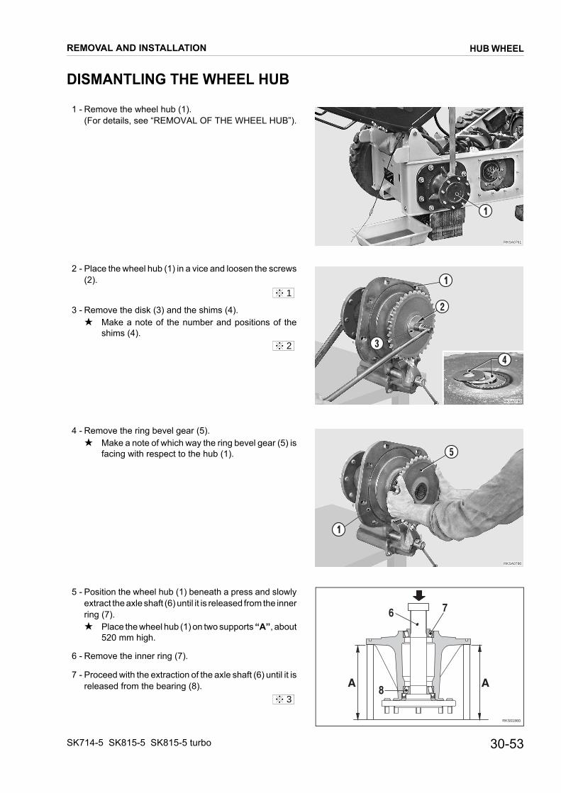
DISMANTLING THE WHEEL HUB
1 - Remove the wheel hub (1).
RKSA0761
1
RKSA0780
1
2
3
4
RKSA0790
1
5
RKS01860
AA
6 7
8
(For details, see “REMOVAL OF THE WHEEL HUB”).
2 - Place the wheel hub (1) in a vice and loosen the screws (2).
3 - Remove the disk (3) and the shims (4).★ Make a note of the number and positions of the
shims (4).
4 - Remove the ring bevel gear (5).★ Make a note of which way the ring bevel gear (5) is
facing with respect to the hub (1).
5 - Position the wheel hub (1) beneath a press and slowly extract the axle shaft (6) until it is released from the inner ring (7).★ Place the wheel hub (1) on two supports “A”, about
520 mm high.
6 - Remove the inner ring (7).
7 - Proceed with the extraction of the axle shaft (6) until it is released from the bearing (8).
1
2
3
REMOVAL AND INSTALLATION
SK714-5 SK815-5 SK815-5 turbo
HUB WHEEL
30-53

8 - Place the hub (1) in a vice and extract the seal ring (9).
RKSA0800
1
7
8
9
RKSA0810
5
6
x
★ Mount a new seal ring (9) each time the hub is dis-mantled.
9 - Extract the outer rings (7) and (8).
ASSEMBLY OF THE HUB WHEEL• To install, reverse removal procedure.
Screw: 294 Nm
1 - Take the existing measurement “X” between the axle shaft (6) and the ring bevel gear (5).
2 - Calculate the thickness of shim that should be inserted between the disc (3) and the ring bevel gear (5) using the following formula:
Z = X – SS = the shim packX = the measurement takenZ = residual clearance (0.05–0.125)
For example: clearance measured X = 0.570Addition of two shims of 0.2 and one of 0.1
3 - Check that the measurement X lies within the permis-sible limits.
★ Grease the bearings (7) and (8).
Bearings: Lithium EP NLGI 2
★ Grease the lip of the seal ring (9).
Seal ring: Lithium EP NLGI 2
4
1
2
3
4
REMOVAL AND INSTALLATION
30-54
HUB WHEEL
SK714-5 SK815-5 SK815-5 turbo

REMOVAL OF THE FINAL DRIVE
1 - Disconnect the gearing chains (1) from the final drive
RKSA0820
1
2
RKSA0830
2
3
4
5
RKSA0840
2
RKSA0850
2
6
7
(2). (For details, see “REMOVAL OF WHEEL HUB”).
2 - Remove the complete hydraulic pump. (For details, see “REMOVAL OF HYDRAULIC PUMP”).
3 - Disconnect from the final drive (2) the supply pipes (3), the speed increment pipe (4) and the drainage pipe (5).★ Plug the tubes to prevent entry of impurities.
4 - Attach the final drive (2) to some hoisting tackle and ap-ply a slight tension to the ropes.
5 - Loosen the 10 screws (6) and take out the complete final drive (2).★ Check the condition of the O-ring (7) and substitute
a new one if necessary.
Final drive: 54 kg
REMOVAL AND INSTALLATION
SK714-5 SK815-5 SK815-5 turbo
FINAL DRIVE
30-55

INSTALLATION OF THE FINAL DRIVE
• To install, reverse removal procedure.
★ Grease the O-ring.
O-ring: Lithium EP NLGI 2
Screws: 120 Nm
Screws: Loctite 270
1
REMOVAL AND INSTALLATION
30-56
FINAL DRIVE
SK714-5 SK815-5 SK815-5 turbo

REMOVAL OF THE RAISING CYLINDER
Lower the working equipment until it is resting on the
RKSA0860
2
1
RKSA0870
3
4
RKSA0880
5
6
7
RKSA0890
89
10
ground.
Release residual pressures from all circuits. (For details, see «20. TESTING AND ADJUST-MENTS»).
1 - Loosen the screw (1) and remove the pin (2).
★ Only for the RH cylinder Disconnect the safety rod (3) from the boom (4).
2 - Loosen the clamps (5) and remove the protection (6).
3 - Disconnect the pipe (7).★ Plug the tube (7) and the union to prevent entry of
impurities.
4 - Disconnect the pipe (8).★ Plug the tube (8) and the union to prevent entry of
impurities.
5 - Loosen the screw (9) and remove the pin (10).
INSTALLATION OF THE RAISING CYLINDER• To install, reverse removal procedure.
Inside the bushings: Lithium EP MS2 NLGI 2
Pin screws: 49 Nm
When aligning the positions between the hole and the pin, run the engine at low idling. Do not insert fingers into the holes to check align-ment.
1 - Start the engine and bleed the air from the cylinder. (For details, see «20. TESTING AND ADJUSTMENTS»).★ After bleeding the air, check the level of oil in the
tank.
1 2
1 2
1
2
REMOVAL AND INSTALLATION
SK714-5 SK815-5 SK815-5 turbo
RAISING CYLINDER
30-57
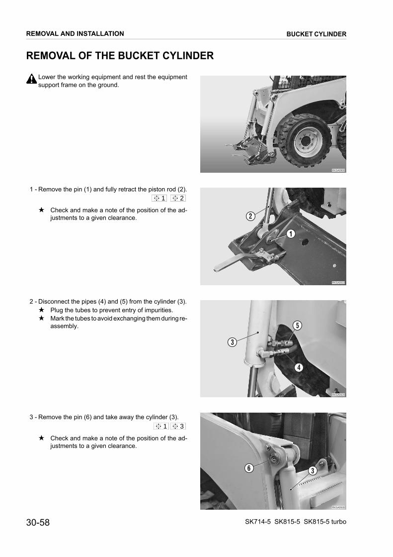
REMOVAL OF THE BUCKET CYLINDER
Lower the working equipment and rest the equipment
RKSA0900
RKSA0910
1
2
RKSA0920
3
4
5
RKSA0930
36
support frame on the ground.
1 - Remove the pin (1) and fully retract the piston rod (2).
★ Check and make a note of the position of the ad-justments to a given clearance.
2 - Disconnect the pipes (4) and (5) from the cylinder (3).★ Plug the tubes to prevent entry of impurities.★ Mark the tubes to avoid exchanging them during re-
assembly.
3 - Remove the pin (6) and take away the cylinder (3).
★ Check and make a note of the position of the ad-justments to a given clearance.
1 2
1 3
REMOVAL AND INSTALLATION
30-58
BUCKET CYLINDER
SK714-5 SK815-5 SK815-5 turbo

INSTALLATION OF THE BUCKET CYLINDER
• To install, reverse removal procedure.
�������
� ����� � �����
RKS02460MAX 1mmMAX 1mm
When aligning the positions between the hole and the pin, do not insert fingers into the holes to check alignment.
Inside the bushings: Lithium EP MS2 NLGI 2
Pin screws: 49 Nm
★ Insert the removed shims and, if necessary, add more until the residual clearance is about 1 mm.
★ Insert the removed shims and, if necessary, add more until the residual clearance is about 1 mm.
1 - Start the engine and bleed the air from the cylinder. (For details, see «20. TESTING AND ADJUSTMENTS»).★ After bleeding the air, check the level of oil in the
tank
1
2
3
REMOVAL AND INSTALLATION
SK714-5 SK815-5 SK815-5 turbo
BUCKET CYLINDER
30-59
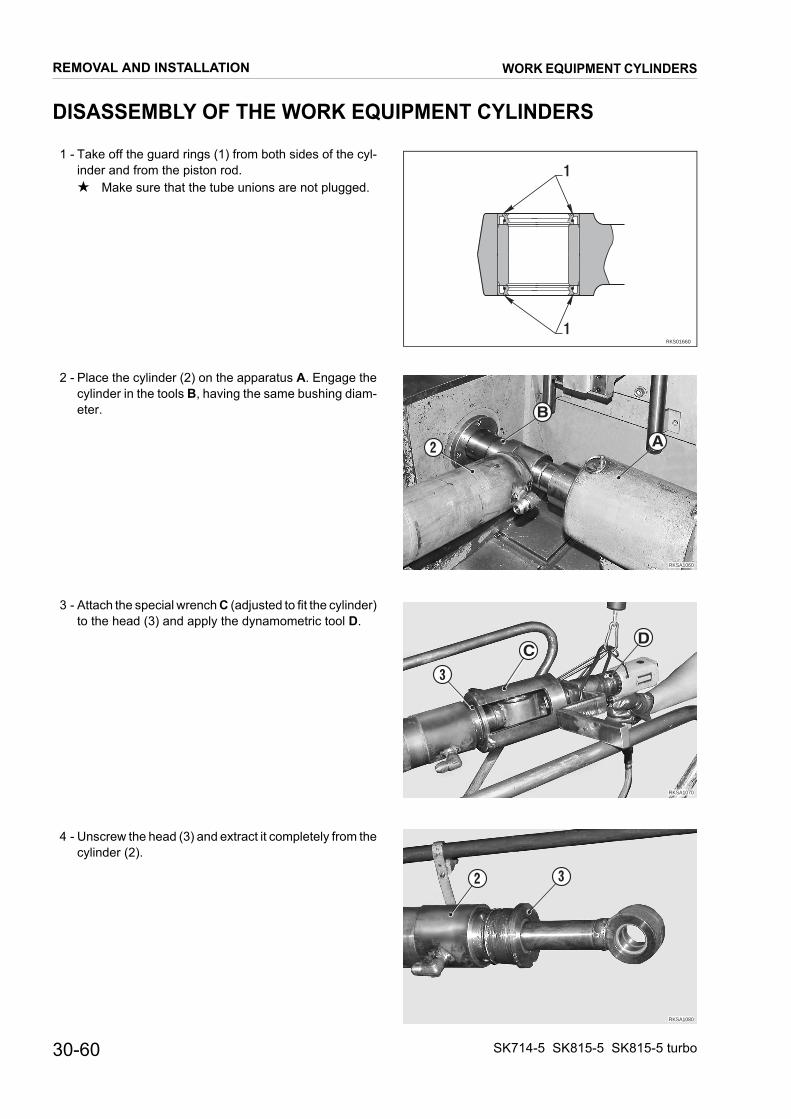
DISASSEMBLY OF THE WORK EQUIPMENT CYLINDERS
1 - Take off the guard rings (1) from both sides of the cyl-
RKS01660
1
1
RKSA1060
2 A
B
RKSA1070
3
DC
RKSA1080
32
inder and from the piston rod.★ Make sure that the tube unions are not plugged.
2 - Place the cylinder (2) on the apparatus A. Engage the cylinder in the tools B, having the same bushing diam-eter.
3 - Attach the special wrench C (adjusted to fit the cylinder) to the head (3) and apply the dynamometric tool D.
4 - Unscrew the head (3) and extract it completely from the cylinder (2).
REMOVAL AND INSTALLATION
30-60
WORK EQUIPMENT CYLINDERS
SK714-5 SK815-5 SK815-5 turbo

5 - Raise the cylinder and hook the piston rod to the mobile
RKSA1090
2
4
A
RKSA1100
4
5
6
DE
group of the tool A.
6 - Extract the piston rod group (4) from the cylinder.
7 - Remove the cylinder (2) and the piston rod group.
8 - Lock the complete piston rod (4) onto the apparatus A.
9 - Attach the socket wrench E to the lock nut (5) of the pis-ton (6) and, using the dynamometric tool with a multi-plier D, remove the nut.★ Socket wrench measurement: 32 mm
10 - Take all the groups to pieces and remove all the seals, guard rings and guide rings.
The seals, guard rings, and guide rings cannot be used again.
REMOVAL AND INSTALLATION
SK714-5 SK815-5 SK815-5 turbo
WORK EQUIPMENT CYLINDERS
30-61

ASSEMBLY OF THE WORK EQUIPMENT CYLINDERS
★ Take great care not to damage the seal and the sliding
RKSA1110
3
7
3
F
RKSA1120
8
9
G
RKS01800
3
7 9
10 11 12
8
surfaces.
★ Prepare each individual component before commenc-ing the final assembly.
1. Assembly of the cylinder head
1 - Position the guard ring (7) and, using a press and the push rod F, press it home in the head (3).★ Check the orientation carefully.
2 - Mount the snap ring (8).
3 - Using the tool G, mount the lip-seal (9).★ Check that the lips face into the cylinder.
4 - Mount the O-ring (10), the anti-extrusion ring (11) and the O-ring (12) onto the cylinder head (3).
REMOVAL AND INSTALLATION
30-62
WORK EQUIPMENT CYLINDERS
SK714-5 SK815-5 SK815-5 turbo

2. Piston assembly
RKSA1130
13 14 15
H
RKSA1140
J14 15 1615
13
RKSA1150
4
17
K
B
RKSA1160
4 34L
1 - Using the tool H, mount the piston seal. Mount in se-quence the rubber ring (13), the outer seal (14) and theanti-extrusion rings (15).
2 - Mount the guide ring (16).
3 - Calibrate the diameter of the gasket (14) of the piston(6), mounting the group beneath the press and using thecalibrating ring J adapted to fit the piston diameter.
3. Piston rod group assembly
1 - Using a press and the tool B adapted to the diameter, in-sert the bushing (17) into the piston rod (4).
2 - Insert the support K beneath the piston rod.
3 - Mount the pilot boss L adapted to the diameter onto theextremity of the piston rod.
4 - Slide the head (3) onto the piston rod (4).
5 - Remove the pilot boss L from the extremity of the pistonrod.
REMOVAL AND INSTALLATION
SK714-5 SK815-5 SK815-5 turbo
WORK EQUIPMENT CYLINDERS
30-63

30-6
6 - M
7 - Mww
4. C
1 - M
2 - P(2★
3 - L(2
4 - Ma
REMO
ount the complete piston (6).
RKSA1170
6
RKSA1101
E D
RKSA1061
19
B
A
RKSA1180
2 M
ount the nut (5) that secures the piston and tighten itith the socket wrench E and the dynamometric toolith a multiplier D.
Nut: Loctite 262
Nut: Raising cylinder: 422±42 Nm Bucket cylinder: 343±34 Nm
ylinder assembly
ount the tools A onto the apparatus B.
osition the bushing (20) and mount it onto the cylinder).
Leave the cylinder in position, ready for the next as-sembly operation.
ubricate the threading and the first part of the cylinder).
Cylinder: Lithium EP NLGI 2
ount the two halves of the tool M, adapted to the di-meter, onto the mouthpiece of the cylinder (2).
5
2
VAL AND INSTALLATION
4
WORK EQUIPMENT CYLINDERS
SK714-5 SK815-5 SK815-5 turbo

5 - Mount the piston rod group (4) onto the tool A and raise
RKSA1091
2
4
A
M
RKSA1071
3
2
CD
the mobile part up to the end of its stroke.
6 - Put the cylinder (2) into a vertical position and guide thepiston into the tool M.
7 - Lower the apparatus supporting the piston rod (4) in or-der to insert the piston into the cylinder liner (2).
8 - Remove the tool M from the cylinder and then lower theapparatus A even further, until the head (3) and the pis-ton rod approach the cylinder.
9 - Place the cylinder (2) in position for screwing in the head(3).
10 - Insert the head into the cylinder and screw it in by handfor a few turns.
11 - Attach the special wrench C to the dynamometric tool Dand screw the head (3) fully home.
Head:• Raising cylinder: 412±41 Nm• Bucket cylinder: 441±44 Nm
12 - Mount the guard rings (1) on both sides of the cylinderand the piston rod.
REMOVAL AND INSTALLATION
SK714-5 SK815-5 SK815-5 turbo
WORK EQUIPMENT CYLINDERS
30-65
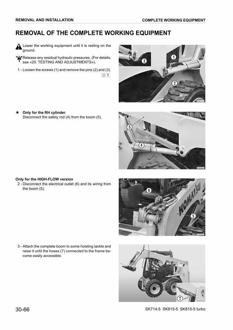
30-6
REM
Lg
Rs
1 - L
★ OD
Only 2 - D
th
3 - Arac
REMO
OVAL OF THE COMPLETE WORKING EQUIPMENT
ower the working equipment until it is resting on the
RKSA1210
1
2
3
RKSA0871
4
5
RKSA0970
5
6
RKSA09407
round.
elease any residual hydraulic pressures. (For details,ee «20. TESTING AND ADJUSTMENTS»).
oosen the screws (1) and remove the pins (2) and (3).
nly for the RH cylinder.isconnect the safety rod (4) from the boom (5).
for the HIGH-FLOW versionisconnect the electrical outlet (6) and its wiring frome boom (5).
ttach the complete boom to some hoisting tackle andise it until the hoses (7) connected to the frame be-
ome easily accessible.
1
VAL AND INSTALLATION
6
COMPLETE WORKING EQUIPMENT
SK714-5 SK815-5 SK815-5 turbo
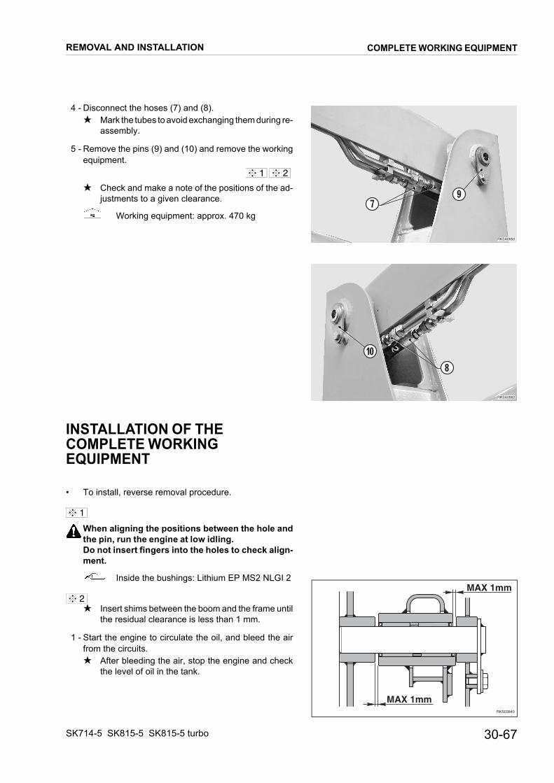
4 - Disconnect the hoses (7) and (8).
RKSA0950
79
RKSA0960
8
10
���������������
�������
★ Mark the tubes to avoid exchanging them during re-assembly.
5 - Remove the pins (9) and (10) and remove the workingequipment.
★ Check and make a note of the positions of the ad-justments to a given clearance.
Working equipment: approx. 470 kg
INSTALLATION OF THECOMPLETE WORKINGEQUIPMENT
• To install, reverse removal procedure.
When aligning the positions between the hole andthe pin, run the engine at low idling.Do not insert fingers into the holes to check align-ment.
Inside the bushings: Lithium EP MS2 NLGI 2
★ Insert shims between the boom and the frame untilthe residual clearance is less than 1 mm.
1 - Start the engine to circulate the oil, and bleed the airfrom the circuits.★ After bleeding the air, stop the engine and check
the level of oil in the tank.
1 2
1
2
REMOVAL AND INSTALLATION
SK714-5 SK815-5 SK815-5 turbo
COMPLETE WORKING EQUIPMENT
30-67
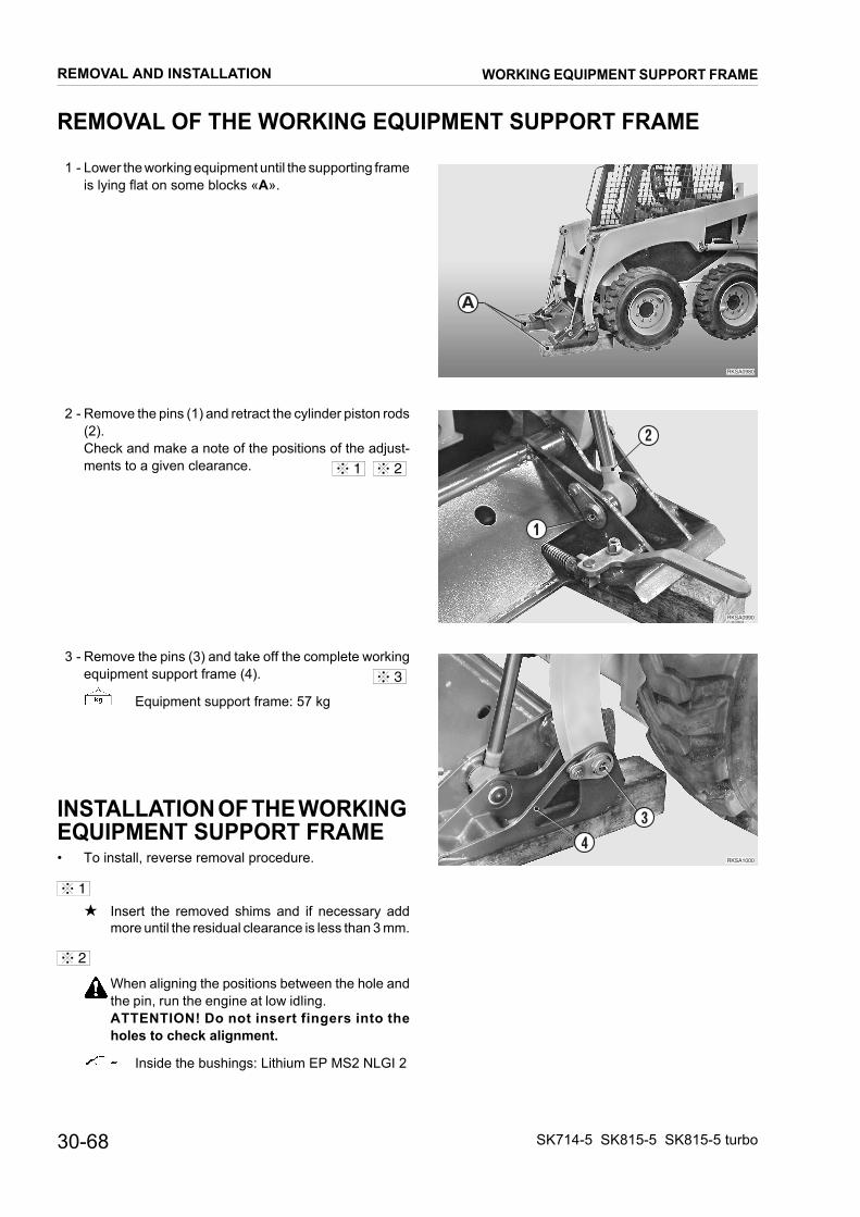
30-6
REM
1 - Lis
2 - R(2Cm
3 - Re
INSEQU• T
★
1
2
REMO
OVAL OF THE WORKING EQUIPMENT SUPPORT FRAME
ower the working equipment until the supporting frame
RKSA0980
RKSA0990
1
2
RKSA1000
4
3
lying flat on some blocks «A».
emove the pins (1) and retract the cylinder piston rods).heck and make a note of the positions of the adjust-ents to a given clearance.
emove the pins (3) and take off the complete workingquipment support frame (4).
Equipment support frame: 57 kg
TALLATION OF THE WORKING IPMENT SUPPORT FRAME
o install, reverse removal procedure.
Insert the removed shims and if necessary addmore until the residual clearance is less than 3 mm.
When aligning the positions between the hole andthe pin, run the engine at low idling.ATTENTION! Do not insert fingers into theholes to check alignment.
Inside the bushings: Lithium EP MS2 NLGI 2
A
1 2
3
VAL AND INSTALLATION
8
WORKING EQUIPMENT SUPPORT FRAME
SK714-5 SK815-5 SK815-5 turbo

STANDARD MAINTENANCE
P.T.O. ........................................................................ 2Transmission ............................................................. 3Final drive .................................................................. 4Hydraulic pump.......................................................... 5Control valve.............................................................. 8R.H. PPC valve........................................................ 14L.H. PPC valve ........................................................ 15Pattern change valve (Optional) .............................. 17Cylinders.................................................................. 18Working equipment.................................................. 20
40-1SK714-5 SK815-5 SK815-5 turbo

STANDARD MAINTENANCE P.T.O.
P.T.O.
RKS01091
195 Nm
80 Nm
80 Nm
40-2 SK714-5 SK815- SK815-5 turbo5

TRANSMISSION
Sectione A - A RKS01440
AA
118 Nm
294 Nm
200 Nm
with Loctite 27029 Nm
186 Nm
STANDARD MAINTENANCE
SK714-5 SK815-5 SK815-5 turbo
TRANSMISSION
40-3
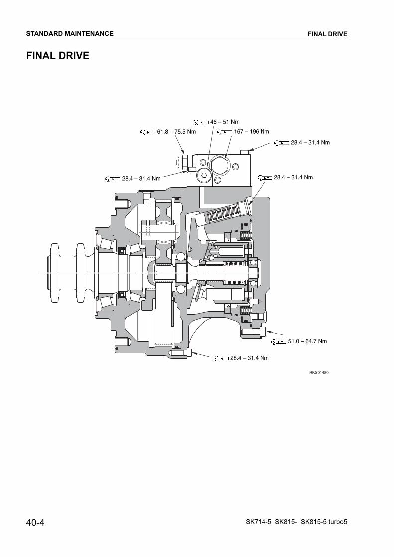
FINAL DRIVE
RKS01480
61.8 – 75.5 Nm
46 – 51 Nm
167 – 196 Nm
28.4 – 31.4 Nm
28.4 – 31.4 Nm 28.4 – 31.4 Nm
28.4 – 31.4 Nm
51.0 – 64.7 Nm
STANDARD MAINTENANCE
40-4
FINAL DRIVE
SK714-5 SK815- SK815-5 turbo5

STANDARD MAINTENANCE HYDRAULIC PUMP
HYDRAULIC PUMPSK714-5
RKS00330
19.6 – 27.4 Nm147 – 186.2 Nm
19.6 – 27.4 Nm147 – 186.2 Nm
58.8 – 73.5 Nm
49 – 58.8 Nm
40-5SK714-5 SK815-5 SK815-5 turbo

0
STANDARD MAINTENANCE HYDRAULIC PUMP
SK815-5 – SK815-5 turbo
RKS0034
19.6 – 27.4 Nm147 – 186.2 Nm
19.6 – 27.4 Nm
147 – 186.2 Nm
58.8 – 73.5 Nm
49 – 58.8 Nm
19.6 – 27.4 Nm
58.8 – 73.5 Nm
40-6 SK714-5 SK815- SK815-5 turbo5

AS VALVE
Unit: mm
N° Check item
Criteria
RemedyStandard size Repair limit
Freelength
Installedlength
Installedload
Freelength
Installedload
1 Spring 38.1 30 52 N – 41.1 N
Replace2 Spring 25.9 23 16.7 N – 13.7 N
3 Spring 40.2 34.5 73.5 N – 58.8 N
RKS01451
Section A - A
31 2
34.3 – 58.8 Nm
44.1 – 53.9 Nm 34.3 – 58.8 Nm
58.8 – 78.4 Nm
STANDARD MAINTENANCE
SK714-5 SK815-5 SK815-5 turbo
HYDRAULIC PUMP
40-7

CONTROL VALVESK815-5 – SK815-5 turbo (SUPER HIGH-FLOW VERSION)
A
View ZRKS00371
A
A
C
CB
B
D
J
H
D
J
H
23.5±3.9 Nm
11.3±1.5 Nm 11.3±1.5 Nm11.3±1.5 Nm
11.3±1.5 Nm
31.9±2.5 Nm
31.9±2.5 Nm
31.9±2.5 Nm
STANDARD MAINTENANCE
40-8
CONTROL VALVE
SK714-5 SK815- SK815-5 turbo5

SK714-5 / SK815-5 – SK815-5 turbo (STANDARD)
RKS00251
Z
View Z
K
K
D D
M
ML
L
23.5±3.9 Nm
11.3±1.5 Nm11.3±1.5 Nm
11.3±1.5 Nm
11.3±1.5 Nm
31.9±2.5 Nm
31.9±2.5 Nm
31.9±2.5 Nm
STANDARD MAINTENANCE
SK714-5 SK815-5 SK815-5 turbo
CONTROL VALVE
40-9

Unit: mm
N° Check item
Criteria
RemedyDetail Permitted value
Free heigh(outside Ø)
Installedlength
Installedload
Freeheigh
Installedload
1 Spool return spring (lift arm) 28.8x17.1 26.8 38.2 N – 30.6 N
Change springs. If there are damage or deformation
2 Spool return spring (bucket) 26.3x17.7 18.5 176.5 N – 141.1N
3 Spool return spring (bucket) 21.6x14.8 10 38.7 N – 31.0 N
4 Spool return spring (ATT) 28x11.5 24.5 137.3 N – 109.8 N
5 Spool return spring (High-Flow) 29x17.6 25.5 131.4 N – 105.1 N
6 Spool return spring (float) 14.7x4.4 9.5 4.9 N – 3.9 N
7 Spring of series - parallel circuit switching valve 38.3x15.2 24 161.8 N – 129.5 N
RKS00383Section B - B
Section A - A
5
7
4
2
3
1
2
6
3
90.7±12.3 Nm
44.1±4.9 Nm
44.1±4.9 Nm
44.1±4.9 Nm
8.3±1.5 Nm
STANDARD MAINTENANCE
40-10
CONTROL VALVE
SK714-5 SK815- SK815-5 turbo5

Unit: mm
N° Check item
Criteria
RemedyDetail Permitted value
Free heigh(outside Ø)
Installedlength
Installedload
Freeheigh
Installedload
1 Spring of unload valve 23.9x18.2 18 74.0 N – 59.2 N
Change springs. If there are damage or deformation
2 Spring of unload valve 18.7x9.3 16 3.4 N – 2.7 N
3 Spring of pressure compensation valve 15.4x6 13 2.5 N – 2.0 N
4 Spring of pressure compensation valve 20x8.4 12 6.9 N – 5.5 N
5 Spring of combination circulating valve 37.5x16.6 22.5 177.5 N – 142.0 N
6 Spring of leveling circulating valve 37.5x15.4 22.5 66.7 N – 53.4 N
7 Spring of flow divider 30.2x9.4 23 2.9 N – 2.4 N
8 Spring of check valve 18.5x3.8 15.5 1.1 N – 0.9 N
RKS00703
Section D - D
Section AA-AA
Section BB-BB
Section C-C
5
7
BBAA
BBAA
8
4
3
6
4
4
4
1 2
3
53.0±5.9 Nm
53.0±5.9 Nm
53.0±5.9 Nm
139.7±22.1 Nm 22.1±2.5 Nm
8.3±1.5 Nm
STANDARD MAINTENANCE
SK714-5 SK815-5 SK815-5 turbo
CONTROL VALVE
40-11
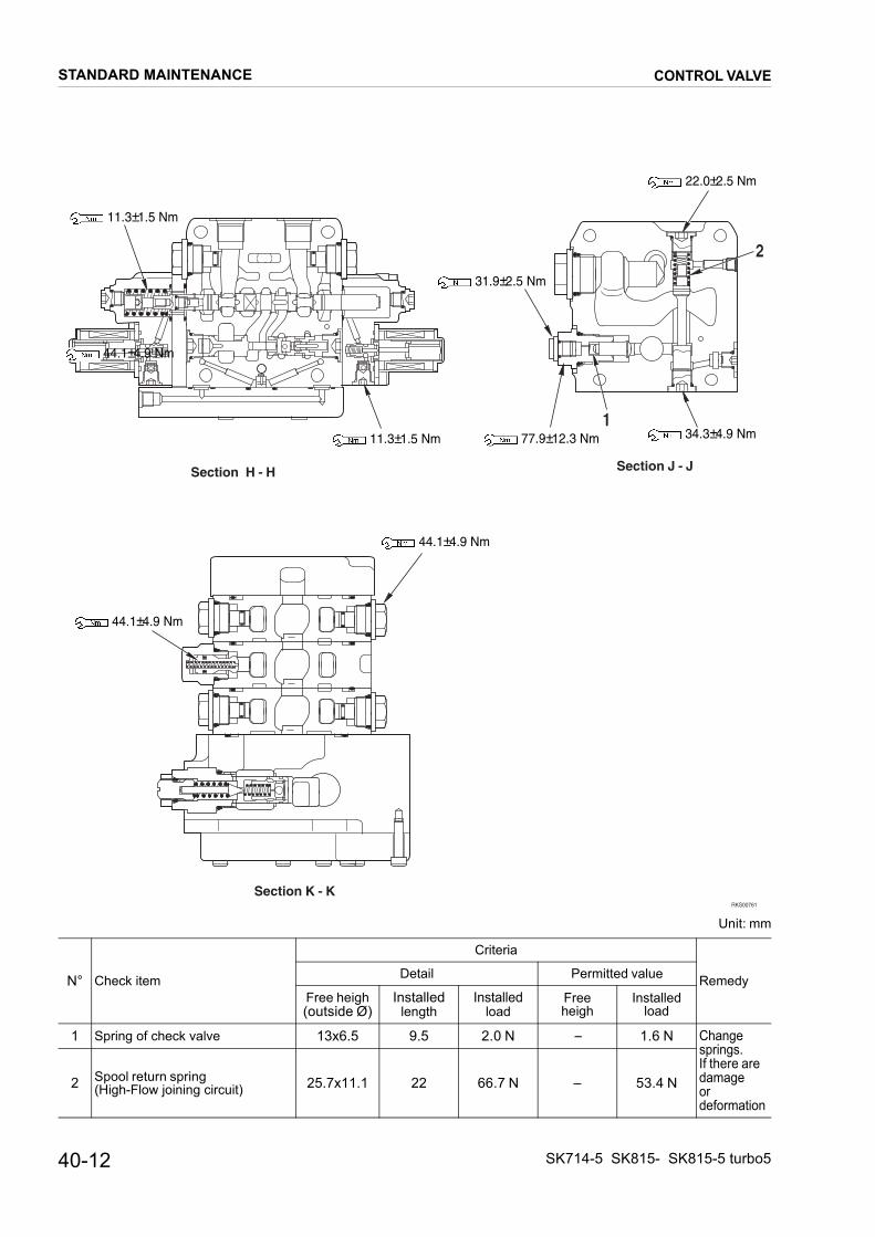
Unit: mm
N° Check item
Criteria
RemedyDetail Permitted value
Free heigh(outside Ø)
Installedlength
Installedload
Freeheigh
Installedload
1 Spring of check valve 13x6.5 9.5 2.0 N – 1.6 N Change springs. If there are damage or deformation
2 Spool return spring (High-Flow joining circuit) 25.7x11.1 22 66.7 N – 53.4 N
Section K - KRKS00761
Section J - JSection H - H
2
1
44.1±4.9 Nm
11.3±1.5 Nm
11.3±1.5 Nm
31.9±2.5 Nm
77.9±12.3 Nm
22.0±2.5 Nm
34.3±4.9 Nm
44.1±4.9 Nm
44.1±4.9 Nm
STANDARD MAINTENANCE
40-12
CONTROL VALVE
SK714-5 SK815- SK815-5 turbo5

Unit: mm
N° Check item
Criteria
RemedyDetail Permitted valueFree heigh(outside Ø)
Installedlength
Installedload
Freeheigh
Installedload
1 Spool return spring (lift arm) 28.8x17.1 26.8 38.2 N – 30.6 N
Change springs. If there are damage or deformation
2 Spool return spring (bucket) 26.3x17.7 18.5 176.5 N – 141.2 N3 Spool return spring (bucket) 21.6x14.8 10 38.7 N – 31.0 N4 Spool return spring (ATT) 29x17.5 25 180.4 N – 144.4 N
5 Spring of series - parallel circuit switching valve 38.3x15.2 24 161.8 N – 129.5 N
6 Spring of unload valve 32.9x18.2 18 74.0 N – 59.2 N7 Spring of unload valve 18.7x9.3 16 3.4 N – 2.7 N
8 Spring of pressure compensation valve 15.4x6 13 2.5 N – 2.0 N
9 Spring of pressure compensation valve 20x8.4 12 6.9 N – 5.5 N
Section L- L
RKS00781
3
1
5
4
2
3
2
Section M - M
76
9
9
8
8
8.3±1.5 Nm
22.1±2.5 Nm139.7±22.1 Nm
53.0±5.9 Nm
31.9±2.5 Nm
STANDARD MAINTENANCE
SK714-5 SK815-5 SK815-5 turbo
CONTROL VALVE
40-13
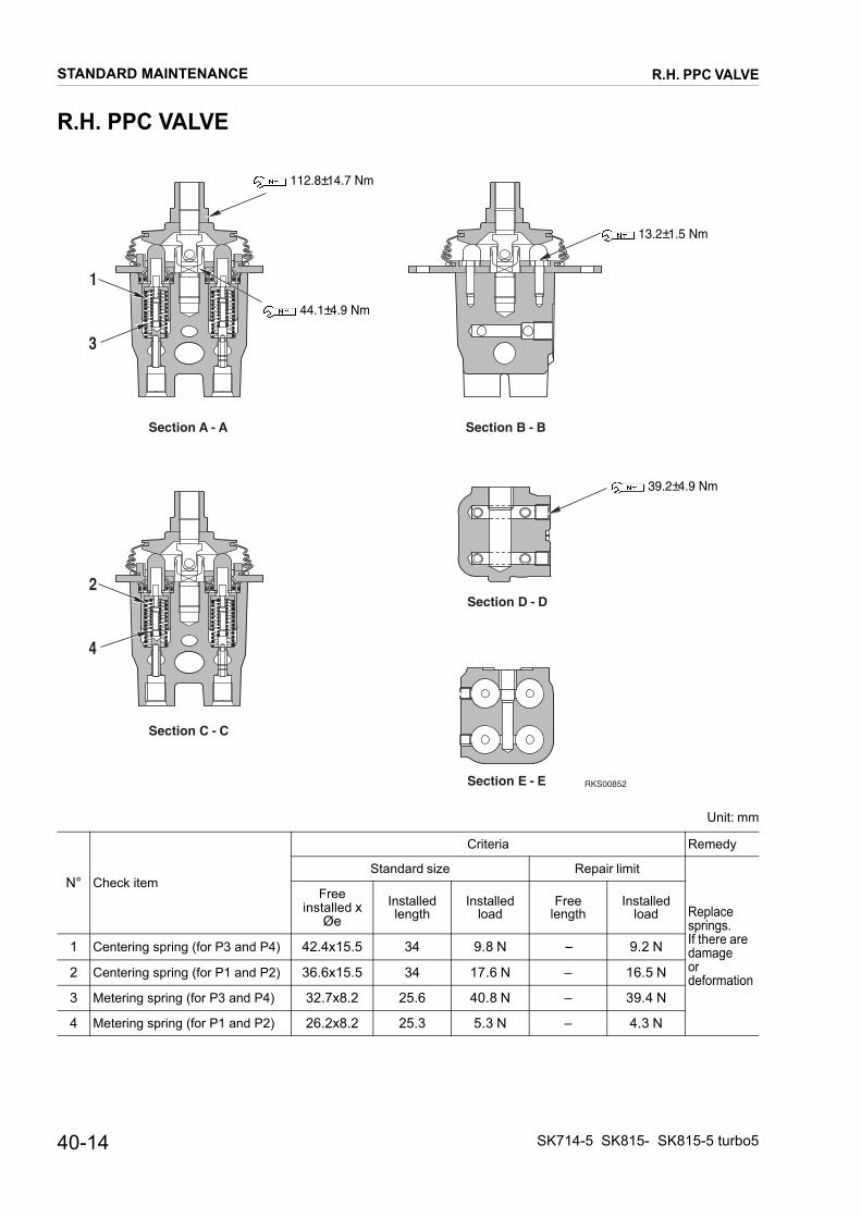
R.H. PPC VALVE
Unit: mm
N° Check item
Criteria Remedy
Standard size Repair limit
Replace springs. If there are damage or deformation
Freeinstalled x
ØeInstalledlength
Installedload
Freelength
Installedload
1 Centering spring (for P3 and P4) 42.4x15.5 34 9.8 N – 9.2 N
2 Centering spring (for P1 and P2) 36.6x15.5 34 17.6 N – 16.5 N
3 Metering spring (for P3 and P4) 32.7x8.2 25.6 40.8 N – 39.4 N
4 Metering spring (for P1 and P2) 26.2x8.2 25.3 5.3 N – 4.3 N
Section A - A Section B - B
Section C - C
Section D - D
Section E - E RKS00852
1
3
2
4
112.8±14.7 Nm
44.1±4.9 Nm
13.2±1.5 Nm
39.2±4.9 Nm
STANDARD MAINTENANCE
40-14
R.H. PPC VALVE
SK714-5 SK815- SK815-5 turbo5
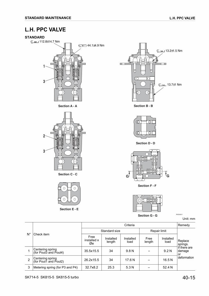
L.H. PPC VALVE
L.H. PPC VALVESTANDARD
Unit: mm
N° Check item
Criteria Remedy
Standard size Repair limit
Replace springs. If there are damage or deformation
Freeinstalled x
ØeInstalledlength
Installedload
Freelength
Installedload
1 Centering spring (for Pout3 and Pout4) 35.5x15.5 34 9.8 N – 9.2 N
2 Centering spring (for Pout1 and Pout2) 26.2x15.5 34 17.6 N – 16.5 N
3 Metering spring (for P3 and P4) 32.7x8.2 25.3 5.3 N – 52.4 N
RKS00911
Section A - A Section B - B
Section C - C
Section D - D
Section E - E
Section F - F
Section G - G
1
3
2
3
GG
112.8±14.7 Nm44.1±4.9 Nm
13.2±1.5 Nm
13.7±1 Nm
STANDARD MAINTENANCE
40-15SK714-5 SK815-5 SK815-5 turbo
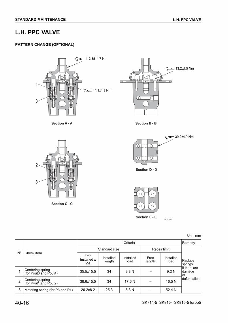
L.H. PPC VALVE
L.H. PPC VALVE
PATTERN CHANGE (OPTIONAL)
Unit: mm
N° Check item
Criteria Remedy
Standard size Repair limit
Replace springs. If there are damage or deformation
Freeinstalled x
ØeInstalledlength
Installedload
Freelength
Installedload
1 Centering spring (for Pout3 and Pout4) 35.5x15.5 34 9.8 N – 9.2 N
2 Centering spring (for Pout1 and Pout2) 36.6x15.5 34 17.6 N – 16.5 N
3 Metering spring (for P3 and P4) 26.2x8.2 25.3 5.3 N – 52.4 N
Section A - A Section B - B
Section C - C
Section D - D
Section E - ERKS00853
1
3
2
3
112.8±14.7 Nm
44.1±4.9 Nm
13.2±1.5 Nm
39.2±4.9 Nm
STANDARD MAINTENANCE
40-16 SK714-5 SK815- SK815-5 turbo5
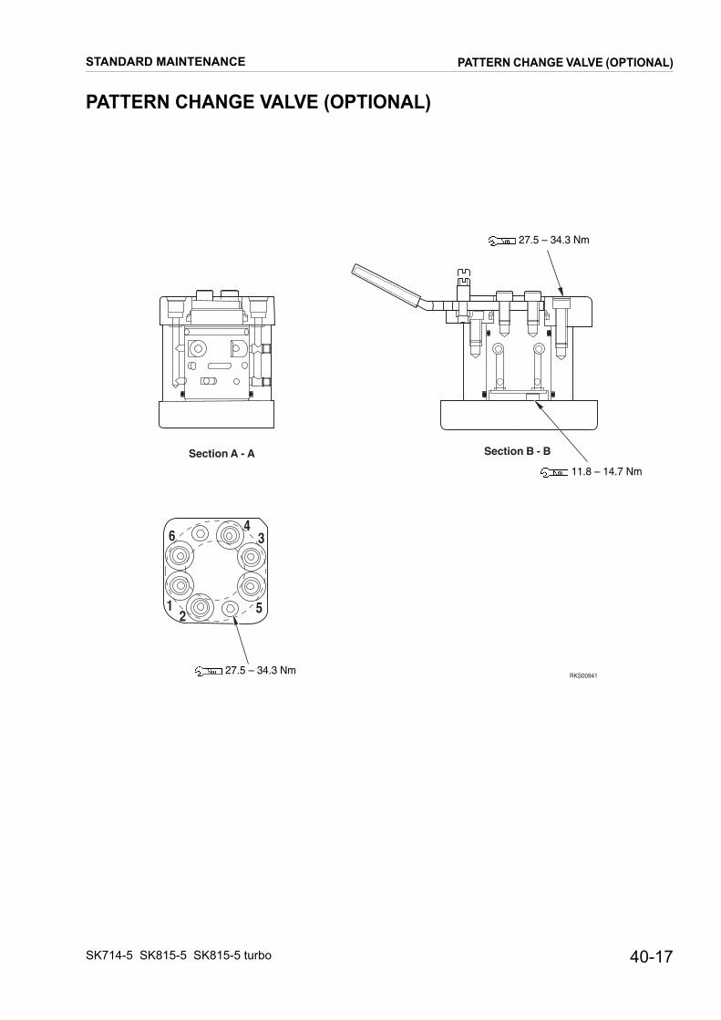
PATTERN CHANGE VALVE (OPTIONAL)
PATTERN CHANGE VALVE (OPTIONAL)
RKS00941
Section B - BSection A - A
51
3
2
64
27.5 – 34.3 Nm
11.8 – 14.7 Nm
27.5 – 34.3 Nm
STANDARD MAINTENANCE
40-17SK714-5 SK815-5 SK815-5 turbo

CYLINDERS
CYLINDERS
Unit: mm
N° Check item Cylinder
Criteria
RemedyStandardsize
Tolerance Minimumclearance
ClearancelimitShaft Hole
1Tolerance between bushing and pistonrod mounting pin
Lifting bucket 35 –0.01–0.05
+ 0.072+ 0.134
0.082–0.184 1.0
Replace bushing
Tilt bucket 35 –0.01–0.05
+ 0.072+ 0.134
0.082–0.184 1.0
2Tolerance between bushing and cylindermounting pin
Lifting bucket 35 –0.01–0.05
+ 0.072+ 0.134
0.082–0.184 1.0
Tilt bucket 35 –0.01–0.05
+ 0.072+ 0.134
0.082–0.184 1.0
3Tolerance between piston rod andcylinder head
Lifting bucket 35 -- 0.025-- 0.087
+ 0.039+ 0
0.025–0.126 0.426
Replace head
Tilt bucket 30 -- 0.020-- 0.072
+ 0.033+ 0
0.020–0.105 0.426
RKS01500
3
1 2
Lifting bucket: 412±41 NmTilt bucket: 441±44 Nm
Lifting bucket: 422±42 Nm (Wrench: 32 mm)Tilt bucket: 343±34 Nm (Wrench: 32 mm)with Loctite 262
STANDARD MAINTENANCE
40-18 SK714-5 SK815- SK815-5 turbo5

PAGE INTENTIONALLYLEFT BLANK

WORKING EQUIPMENT
WORKING EQUIPMENT
��������
����������
������������
�
�
�
��
�
������������
�
�
�
�
STANDARD MAINTENANCE
40-20 SK714-5 SK815- SK815-5 turbo5

WORKING EQUIPMENT
Unit: mm
N° Check item
Criteria
RemedyStandardsize
Tolerance Minimumclearance
ClearancelimitShaft Hole
1 Clearance between bushing and mounting pin of arm and support frame 35 –0.01
–0.05+ 0.072+ 0.134
0.082–0.184 1.0
Replace bushing
2 Clearance between bushing and mounting pin of arm 35 –0.01
–0.05+ 0.072+ 0.134
0.082–0.184 1.0
3 Clearance between bushing and mounting pin lift cylinder (head side) 35 –0.01
–0.05+ 0.072+ 0.134
0.082–0.184 1.0
4 Clearance between bushing and moun-ting pin bucket cylinder (bottom side) 35 –0.01
–0.05+ 0.072+ 0.134
0.082–0.184 1.0
5 Clearance between bushing and mounting pin bucket cylinder (head side) 35 –0.01
–0.05+ 0.072+ 0.134
0.082–0.184 1.0
6 Clearance between bushing and mounting pin lift cylinder (bottom side) 35 –0.01
–0.05+ 0.072+ 0.134
0.082–0.184 1.0
�����������
��������
�������� ��
��
STANDARD MAINTENANCE
40-21SK714-5 SK815-5 SK815-5 turbo

PAGE INTENTIONALLYLEFT BLANK


�������������� � �������������������������������������������� �!��