skalper - asgco.com
TRANSCRIPT

®
SKALPER™
with Force-1
INSTALLATION, OPERATION& MAINTENANCE INSTRUCTIONS
™Force-1
Check us out atwww.asgco.com
Customer ServiceCustomer Service
800-344-4000
ASGCO Mfg., Inc.730 Bangor Rd.Nazareth, PA 18064 610-821-0216FAX 610-778-8991
®© 9/2021 Copyright ASGCO ”Complete Conveyor Solutions”
24 Hour Emergency Service and Parts610-821-0210

™ ASGCO Mfg., Inc. 2 SKALPER w/Force-1
*Note: Light-duty spring is red; heavy duty spring is silver
Full Belt Width
or
Belt Width -6”
Lubricate locking pins
SKALPER
Lubricate inside of channel with supplied grease
Force-1Tensioner
104
8
1
2
12
13
11
9
6
3
75
Components Diagram
1. Skalper Blade
2. Mounting Tube
3. Tensioner Mounting Plate with Bushing
4. Opposite Side Mounting Plate with Bushing
5. Spring (Heavy Duty Spring for 48” belt and wider)*
6. Power Arm
7. Tension Bolt
8. Opposite Side Collar with set screws
9. Spring Locators
10. Blade Locking Pins (2)
11. Tension Nut
12. Set Screws
13. UHMW Bushings
Important Safety Notice
Always observe the basic rules of safety when working with any conveyor system. To avoid injury and equipment damage, be sure that all controls to the conveyor are locked out and the power source is disconnected at all times during installation.
Overall View If mounting structure is not available, additional steel may have to be added. Note: Excess mounting tube may be trimmed after installation.Also note required lubrication of components.

™ ASGCO Mfg., Inc. 3 SKALPER w/Force-1
1. Determine the Critical “N” Dimension
Determining the "N" dimension, the distance from the belt surface to the mounting tube center, is critical to get the maximum cleaning performance from your system. Make sure mounting tube and tensioner system are clear of obstacles.
Note: ±¼” tolerance
Preferred blade tip location
Figure 1: Typical Mounting Position
“N” Dimension Table
Pulley Diameterinches [mm]
12” [300mm]
14” [350mm]
16” [400mm]
18” [450mm]
20” [500mm]
24” [600mm]
30” [750mm]
36” + [900mm]
“N” Dimensioninches [mm]
5-3/8” [137mm]
5” [127mm]
4-3/4” [121mm]
4-1/2” [114mm]
4-1/4” [108mm]
3-7/8” [98mm]
3-1/2” [89mm]
3-1/4” [83mm]
Note the tolerance is ± ¼” [6mm]
"N"
Belt Surface
< If over 500 FPM10 O'Clock
9 O'Clock
8 O'Clock
7 O'Clock
Shaded AreaRepresents NormalInstallation Location
2. Cut Chute Openings
Determine the desired location of the mounting brackets. The required slot sizes/locations are shown for the tensioner side chute cut outs.
8-1/2” [216]
Tensioner SideChute Cut OutStandard Mounting Tube
Blade Height
Tensioner SideChute Cut OutMounting Tube with T-Bar
2-3/8” [60]2” [51]
4” [102]
2-7/8” [73]
9/16” [14]4-3/4” [121]
Opposite SideChute Cut Out
3” [76]
9/16” [14]
4 1/4” [108]
1 13/16” [46]
1” [25]2 1/4” [57]
1 1/4” [31.75]
2” [51]
4” [102]
2” [51]
3” [76]
1 13/16” [46]
1” [25]2 1/4” [57]
1 1/4” [31.75]
2” [51] 2” [51]
4” [102]
9/16” [14]
6 1/2” [165]

™ ASGCO Mfg., Inc. 4 SKALPER w/Force-1
3. Mounting Tube through Cut Outs
Place the mounting tube through the chute cut outs so that the longtube end section is on the tensioner side. Place the blade onto the blade holder. Visually check the blade position and contact with the belt/pulley.
5. Mounting Brackets
Opposite Side
Determine the desired location of the mounting brackets. Attach themounting brackets to the conveyor frame by welding or bolting.
Tensioner Side
4. Selecting Correct
Orientation
The location of the tensioner determines the orientation of the spring / bolt / arm assembly. Facing the head pulley as material would come towards you, configure the tensioner as shown:
Assemble this way if tensioner is on the left.
Assemble this way if tensioner is on the right.

OPERATION & MAINTENANCE
Tensioning theForce-1Tensioner
The following chart shows the “D” dimensions for a particuler blade width. Once Force-1 tensioner in place, tighten all set screws to 70 ft-lbs (95 N-m).
1.)
2.)
3.)
4.)
5.)
6.)
BLADE"d"
DIMENSION
18 3.125
24 3.000
30 2.750
36 2.625
42 2.375
48 3.375
54 3.250
64 3.125
72 2.875
84 2.625
LIGHT
DUTY
SPRING
(RED)
HEAVY
DUTY
SPRING
(SILVER)
STARTING DIMENSION = 3.6250"
™ ASGCO Mfg., Inc. 5 SKALPER III w/Force-1
Select the “D” dimension for your application from the table above. Use the hex nut to adjust the spring force via the “D” dimension. Begin with D = 3.625” (roughly) and tighten until the proper value is reached.
The “D” dimension relates to approximately one (1) lb. of force per inch of blade width - approximately 30 lbs of force for a 30" blade. Observe the operation of the Skalper blade. Loosen the nut until cleaning performance suffers; then tighten it slightly to obtain adequate cleaning. Using the minimum amount of blade force required to clean the belt will extend blade life.
Frequent inspections the key to proper belt cleaning and easy scraper servicing. Weekly inspections are recommended, but actual service frequency may vary widely depending on various plant operating conditions.
Inspect the belt surfaces and edges for cracks, splits, tears, holes, or any other worn or damaged condition occurring on the surfaces or edges of the belt itself. If necessary, make repairs to the belt. Wash the entire cleaner regularly to prevent excessive build-up. Check the tightness of all fasteners.
Inspect the cleaner for proper operation. Adjust torque as required.
Replace the Skalper blade as required. Use only ASGCO Manufacturing approved replacement scraper blades
Full Belt Width
or
Belt Width -6”
Lubricate locking pins
SKALPER
Lubricate inside of channel with supplied grease
10
4
8
1
2
™ ASGCO Mfg., Inc. 6 SKALPER w/Force-1
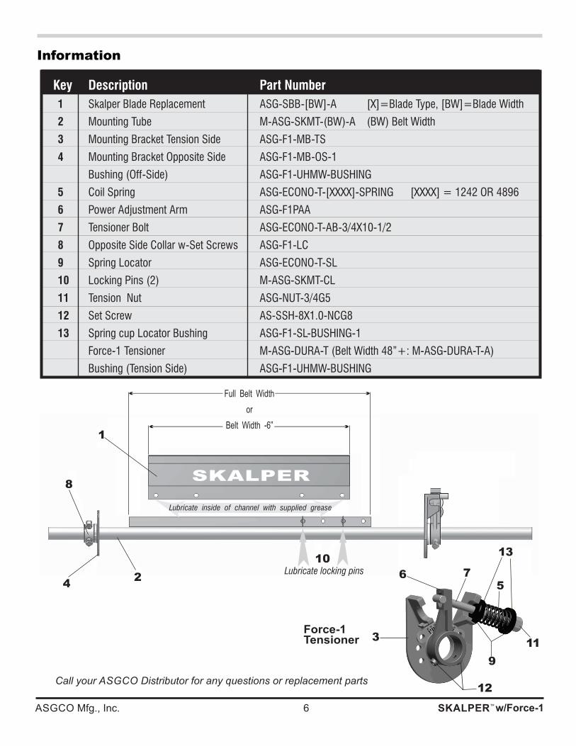
Information
TROUBLESHOOTING
Key Description Part Number
1 Skalper Blade Replacement ASG-SBB-[BW]-A [X]=Blade Type, [BW]=Blade Width
2 Mounting Tube M-ASG-SKMT-(BW)-A (BW) Belt Width
3 Mounting Bracket Tension Side ASG-F1-MB-TS
4 Mounting Bracket Opposite Side ASG-F1-MB-OS-1
Bushing (Off-Side) ASG-F1-UHMW-BUSHING
5� Coil Spring� ASG-ECONO-T-[XXXX]-SPRING [XXXX] = 1242 OR 4896
6� Power Adjustment Arm� ASG-F1PAA
7� Tensioner Bolt� ASG-ECONO-T-AB-3/4X10-1/2
8 Opposite Side Collar w-Set Screws ASG-F1-LC
9� Spring Locator� ASG-ECONO-T-SL
10 Locking Pins (2) M-ASG-SKMT-CL
11� Tension Nut� ASG-NUT-3/4G5
12� Set Screw� AS-SSH-8X1.0-NCG8
13 Spring cup Locator Bushing ASG-F1-SL-BUSHING-1
Force-1 Tensioner M-ASG-DURA-T (Belt Width 48”+: M-ASG-DURA-T-A)
Bushing (Tension Side) ASG-F1-UHMW-BUSHING
Call your ASGCO Distributor for any questions or replacement parts
Force-1Tensioner
12
13
11
9
6
3
75

™ ASGCO Mfg., Inc. 7 SKALPER w/Force-1
TROUBLE SHOOTING
PROBLEM SOLUTION
Excess vibration of the scraper. Make certain all bolts are tight and the pin is securely engaged on the tensioner.
Ensure the cleaners n-dimension is proper (See Table and Figure 1).
Excess carryback. Check for excess build-up on the scraper.
Check for proper Scraper tension. Put additional tension on cleaner.
Check for non-uniform scraper wear.
Check n-dimension.
Clean the back-side of the belt cleaner.
Check for wear on the cleaning tips. Check thickness of carry-back. If the cleaner must remove more than about 1/8” of material then an additional cleaner may be needed.
Frozen material on scraper. Place heaters near scraper to melt frozen material. (Use caution not to burn belt or cleaner)
Blade wearing in center BVW-6” BW-12 (Put a new blade on the concentrates cleaning in the center of the flow of the material.
Blade wearing more on one side Check n-dimension.