skanstacker 300 - mdc.custhelp.com
TRANSCRIPT

SkanStacker 300User Guide
AN ALL-INCLUSIVE AUTOMATIC MICROPLATE WASHER

1311 Orleans DriveSunnyvale, CA 94089 USA0112-0065 Rev. B
Copyright© Copyright 2004, Molecular Devices Corporation. All rights reserved. No part of this publication may be photocopied or reproduced in any form with-out the prior written permission of Molecular Devices Corporation, 1311 Orleans Drive, Sunnyvale, California, 94089, USA.
Trademarks and PatentsSkanWasher is a trademark of Molecular Devices Corporation (MDC) and is not to be used in any type of promotion or advertising without permission from MDC. All other trademarks or registered trademarks are the property of their respective owners.
DisclaimerMolecular Devices Corporation reserves the right to change its products and services at any time to incorporate technological developments. This user guide is subject to change without notice. Although this user guide has been prepared with every precaution to ensure accuracy, Molecular Devices Corporation assumes no liability for any errors or omissions, nor for any damages resulting from the application or use of this information.
ii SkanStacker 300 User Guide

Table of Contents
Chapter 1: Introduction . . . . . . . . . . . . . . . . . . . . . . . . . . . . . . . . . . . . . . . . 1Overview . . . . . . . . . . . . . . . . . . . . . . . . . . . . . . . . . . . . . . . . . 1About This Guide . . . . . . . . . . . . . . . . . . . . . . . . . . . . . . . . . . 2Key to Symbols . . . . . . . . . . . . . . . . . . . . . . . . . . . . . . . . . . . . 2Safety Features . . . . . . . . . . . . . . . . . . . . . . . . . . . . . . . . . . . . 3Serial Number . . . . . . . . . . . . . . . . . . . . . . . . . . . . . . . . . . . . . 3Package Content . . . . . . . . . . . . . . . . . . . . . . . . . . . . . . . . . . . 3
Chapter 2: Installation. . . . . . . . . . . . . . . . . . . . . . . . . . . . . . . . . . . . . . . . . . 5
Chapter 3: Parts and Description . . . . . . . . . . . . . . . . . . . . . . . . . . . . . . . . . 9Wash Head. . . . . . . . . . . . . . . . . . . . . . . . . . . . . . . . . . . . . . . . 9Microplate Lift. . . . . . . . . . . . . . . . . . . . . . . . . . . . . . . . . . . . . 9Control Panel . . . . . . . . . . . . . . . . . . . . . . . . . . . . . . . . . . . . . 10LED Display . . . . . . . . . . . . . . . . . . . . . . . . . . . . . . . . . . . . . 11Instrument Rear Connections . . . . . . . . . . . . . . . . . . . . . . . . 11Pressure/Vacuum Washer Parts. . . . . . . . . . . . . . . . . . . . . . . 13
External Vacuum Source. . . . . . . . . . . . . . . . . . . . . . . . . 13Hydrophobic Filter . . . . . . . . . . . . . . . . . . . . . . . . . . . . . 13Internal Pressure Source . . . . . . . . . . . . . . . . . . . . . . . . . 13
Chapter 4: Software Configuration. . . . . . . . . . . . . . . . . . . . . . . . . . . . . . . 14Setup Function. . . . . . . . . . . . . . . . . . . . . . . . . . . . . . . . . . . . 15
Edit Program . . . . . . . . . . . . . . . . . . . . . . . . . . . . . . . . . . 15Edit Options . . . . . . . . . . . . . . . . . . . . . . . . . . . . . . . . . . 21
Chapter 5: Operation. . . . . . . . . . . . . . . . . . . . . . . . . . . . . . . . . . . . . . . . . . 24Starting a Wash Program. . . . . . . . . . . . . . . . . . . . . . . . . . . . 24
Chapter 6: Maintenance . . . . . . . . . . . . . . . . . . . . . . . . . . . . . . . . . . . . . . . 26Daily Maintenance. . . . . . . . . . . . . . . . . . . . . . . . . . . . . . . . . 26Empty Wash Head Procedure . . . . . . . . . . . . . . . . . . . . . . . . 27Weekly Maintenance . . . . . . . . . . . . . . . . . . . . . . . . . . . . . . . 29Monthly Maintenance . . . . . . . . . . . . . . . . . . . . . . . . . . . . . . 30Advanced Maintenance . . . . . . . . . . . . . . . . . . . . . . . . . . . . . 31
Dispense test . . . . . . . . . . . . . . . . . . . . . . . . . . . . . . . . . . 31Clogged Probes . . . . . . . . . . . . . . . . . . . . . . . . . . . . . . . . 31Removal of wash head . . . . . . . . . . . . . . . . . . . . . . . . . . 32
SkanStacker 300 User Guide iii

Replacing Probes . . . . . . . . . . . . . . . . . . . . . . . . . . . . . . . 33
Chapter 7: Troubleshooting. . . . . . . . . . . . . . . . . . . . . . . . . . . . . . . . . . . . . 34Troubleshooting Chart . . . . . . . . . . . . . . . . . . . . . . . . . . . . . . 34Error Messages. . . . . . . . . . . . . . . . . . . . . . . . . . . . . . . . . . . . 37Magazine Alignment . . . . . . . . . . . . . . . . . . . . . . . . . . . . . . . 39
Section A: Right magazine alignment . . . . . . . . . . . . . . . 39Section B: Left magazine alignment . . . . . . . . . . . . . . . . 41
Vacuum Pump Troubleshooting . . . . . . . . . . . . . . . . . . . . . . 43Adjusting vacuum pump . . . . . . . . . . . . . . . . . . . . . . . . . 43Discharge test for vacuum pump . . . . . . . . . . . . . . . . . . . 44Compare pump with internal vacuum sensor . . . . . . . . . 44
Application Tips: SkanWasher 300/ SkanStacker . . . . . . . . . 45
Appendix A: Shipment. . . . . . . . . . . . . . . . . . . . . . . . . . . . . . . . . . . . . . . . A-1
Appendix B: Specifications . . . . . . . . . . . . . . . . . . . . . . . . . . . . . . . . . . . . B-2Physical. . . . . . . . . . . . . . . . . . . . . . . . . . . . . . . . . . . . B-2Performance . . . . . . . . . . . . . . . . . . . . . . . . . . . . . . . . B-2Chemical . . . . . . . . . . . . . . . . . . . . . . . . . . . . . . . . . . . B-2
Appendix C: Warranty . . . . . . . . . . . . . . . . . . . . . . . . . . . . . . . . . . . . . . . C-3
Appendix D: Wash Program Sheets. . . . . . . . . . . . . . . . . . . . . . . . . . . . . . D-5
Index . . . . . . . . . . . . . . . . . . . . . . . . . . . . . . . . . . . . . . . . . . . . . . . . . . . . . . 1-1
iv SkanStacker 300 User Guide

SkanStacker 300 User Guide v
Figure 1: Waste reservoir and vacuum pump. . . . . . . . . . . . . . . . . 2-6Figure 2: Wash and Rinse liquid connection . . . . . . . . . . . . . . . . . 2-7Figure 3: Microplate transfer base . . . . . . . . . . . . . . . . . . . . . . . . . 2-8Figure 4: SkanStacker 300 Instrument . . . . . . . . . . . . . . . . . . . . . . 3-9Figure 5: Control Panel, LCD and Touch Keys . . . . . . . . . . . . . . 3-10Figure 6: Rear of the SkanStacker . . . . . . . . . . . . . . . . . . . . . . . . 3-11Figure 7: Aspirate probe height position . . . . . . . . . . . . . . . . . . . 4-19Figure 8: Dispense probe height position. . . . . . . . . . . . . . . . . . . 4-19Figure 9: Wash head connections. . . . . . . . . . . . . . . . . . . . . . . . . 6-32Figure 10: Right magazine alignment . . . . . . . . . . . . . . . . . . . . . . 7-40Figure 11: Left magazine alignment . . . . . . . . . . . . . . . . . . . . . . . 7-42
Figures

Chapter 1: IntroductionOverviewThe need to thoroughly wash unbound antigens, antibodies, binding proteins, enzymes, or receptors from a solid-phase binding support is one of the most important steps in the enzyme-linked immunosorbent assay (ELISA). The SkanStacker 300 meets this demand and those of other numerous laboratory assays now being performed in 96-well microplates where thorough washing is an essential component of the assay.The SkanStacker is designed to wash 96-well microplates. The process of set-ting up wash parameters is flexible and allows you to modify or choose the following settings:
Aspirate probe height and position in the well for low residual volume.Dispense probe height and position in the well for washing the active part of well.Inlet wash buffer flow rate can be adjusted by changing air pressure. Range 0.00 - 0.60 bar in selected programs.“Overflow” washing with meniscus.Microprocessor-controlled timing.Aspiration from the top of the well with adjustable lift speed controlled by adjusting aspirate time in seconds.Wash all 96 wells simultaneously.Dispense-only function from 100 -350 µl.Dispense volume adjustment.Adjustable vacuum pump with manometer.Electronic air pressure regulation.Automatic handling of up to 25 microplates.
SkanStacker 300 User Guide 1

Introduction
About This GuideChapter 1: This section will give you an introduction to the manual and
details of what to expect in this Guide.Chapter 2: Installation instructions will be outlined.Chapter 3: Details will be given on unit parts to introduce common terminol-
ogy used throughout the manual.Chapter 4: This section will detail use of the software to set up programs and
configuration of the instrument.Chapter 5: General operations will be detailed.Chapter 6: Detailed procedures will be listed for care and maintenance of
instrument. Chapter 7: Troubleshooting tips, error messages, and advanced troubleshoot-
ing will be outlined.Appendix: This section will include instrument specifications, shipping
information, and program sheets.
Key to SymbolsSymbols are used throughout this Guide to indicate important or helpful infor-mation that is not directly part of an instruction. The symbols used are the fol-lowing:
CAUTION: Alerts user to situations that could result in instrument damage or failure to complete a procedure.
!! IMPORTANT: Information that you need to know to perform a task properly.
TIP: Helpful information that can simplify a task.
2 SkanStacker 300 User Guide

Introduction
Safety FeaturesThe SkanStacker is equipped with four sensors that help to safeguard opera-tion before the actual wash. When starting the program, the SkanStacker auto-matically verifies the status of the following:
Pressure pump operating at the correct level (0-600 mbar).Microplate in the microplate lift.Space remaining in the waste reservoir (alarm will sound when 3/4 full).Waste vacuum operating at the correct level (< 900 mbar).
Sensors can be disabled through the Setup menu / Edit Options. Consult page 21 for procedure.
Serial NumberThe serial number of the unit can be found on the left side of the instrument.
Package ContentThe SkanStacker system includes the following:
SkanStacker InstrumentTool kit, including probe cleaner, Allen key, and 7 mm wrench.Power cord: (2) 230 V cables for UK and Europe or (1) 110 V cable User guideReference card (short form guide located in slot on back panel of instrument)Adjustable feet for leveling instrument2 magazinesMagazine transfer baseAerosol shieldWarranty card
Reservoir and Tubing45 L/min vacuum pump with hydrophobic filterBuffer reservoir (4 L); Rinse reservoir (4 L)Waste collection vessel (15 L) with level sensor and alarm waste cable
SkanStacker 300 User Guide 3

Introduction
Tubing setInlet tubing for buffer (blue) and rinse (green)Pressure tubing (yellow)Vacuum waste tubing (red): connects from instrument to 15 liter collection vesselVacuum pump tubing (black): connects from vacuum pump to 15 liter collection vessel
4 SkanStacker 300 User Guide

Installation
Chapter 2: Installation
Step 1 Remove transport bracket.Use an Allen wrench and remove the two allen screws indicated by the number one in the picture below.Use an Allen wrench and remove the two allen screws indicated by the number two in the picture below.
Step 2 Verify voltage is properly set for incoming line voltage.Check that the current voltage setting is pointing to the small white mark.
Step 3 Change voltage setting, if indicated.Pry open the fuse compartment with a small screwdriver.Turn the switch around until the proper setting is pointing to the small white mark on the bottom of the casing.Verify correct fuses are in place; change if indicated.
230 VAC= 1A fuse115 VAC= 2A fuse
TIP: Save the packing material for future use in shipping instrument.
!! IMPORTANT: Fuse compartment is located below the main power receptacle on the back of the instrument.
12
1
2
SkanStacker 300 User Guide 5

Installation
Reinstall switch.
Step 4 Connect the power cord.
Insert the power cord into the receptacle located on the back of the instrument.Plug the power cord into the main power outlet.
Step 5 Connect Waste Reservoir (refer to Figure 1).Connect the outlet tubing line (red) from the Waste port on waste reservoir to the Vacuum port on the side of the instrument (vac-uum grade tubing required with straight-through quick coupling).Connect the waste alarm cable from the waste reservoir to the Waste Alarm port on the back on the instrument located below the power receptacle.Connect vacuum tubing (black) from Vacuum quick connect on waste reservoir to tubing from vacuum pump. (Hydrophobic filter should be connected to tubing from vacuum pump with arrow on filter facing pump.)
Figure 1: Waste reservoir and vacuum pump
CAUTION: Before connecting the main power, ensure that the voltage setting is correct.
Waste ReservoirVacuum Pump
SS 300
Waste Alarm Cable
Vacuum-Grade Tubing
6 SkanStacker 300 User Guide

Installation
Step 6 Connect the Wash and Rinse Liquids (refer to Figure 2).
Connect the pressure tubing (yellow) from the wash buffer and rinse reservoir to the Pressure port on the side of the instrument.
Connect the tubing from the wash buffer (blue) and rinse res-ervoir (green) to the Inlet and Rinse ports on the left side of the instrument.
Figure 2: Wash and Rinse liquid connection
Step 7 Load microplates into magazines using the microplate transfer base (see Figure 3).
Step 8 Insert magazines in slots on top of instrument.
CAUTION: It is recommended to use the waste collection vessel provided by Molecular Devices. These bottles are implosion proof with a “tankful” sensor and a built-in foam reducer.
!! IMPORTANT: Do not fill the reservoir bottles completely. Allow approximately 25% free space for air pressure.
Waste ReservoirVacuum Pump
Washhead
InletRinse
Hyd. Filter
VacuumPressureR
insePressureInlet
SkanStacker 300 User Guide 7

Installation
Step 9 Set up vacuum pump and adjust if necessary (starting pressure 300 mbar).
Figure 3: Microplate transfer base
Microplate Transfer Base
8 SkanStacker 300 User Guide

Parts and Description
Chapter 3: Parts and Description
Figure 4: SkanStacker 300 Instrument
Wash HeadThe wash head contains 96 paired probes: the longer probes are used when aspirating and the shorter probes are used when dispensing. The head is a combined manifold and washhead, equipped with 3 valves, electronic sensors for vacuum and pressure, and a spirit level to assist in leveling the wash head.The wash head is removable, using the two adjustment knobs to remove the washhead. The washhead is lifted up and both the flat cable and air pressure tubing are disconnected. This allows access to its internal channels for cleaning and maintenance.
Microplate LiftThe microplate lift ensures that the microplate is positioned accurately during each stage of the wash program. The function of the lift is to minimize contamination of the wash probes (probes are not submerged into the liquid in the wells). The carriage collects and stacks microplates from the magazines.The vertical velocity of the lift is fixed except during the aspirate function: the longer the aspirate time, the slower the lift moves
Magazine racks
Adjustment Knobs
Control Panel
Wash Head
SkanStacker 300 User Guide 9
Parts and Description
upward toward the aspirate probes. This creates a very gentle aspiration and avoids disturbing the coating in the wells.The lift automatically returns to the home position (lower) when the instrument is powered on.
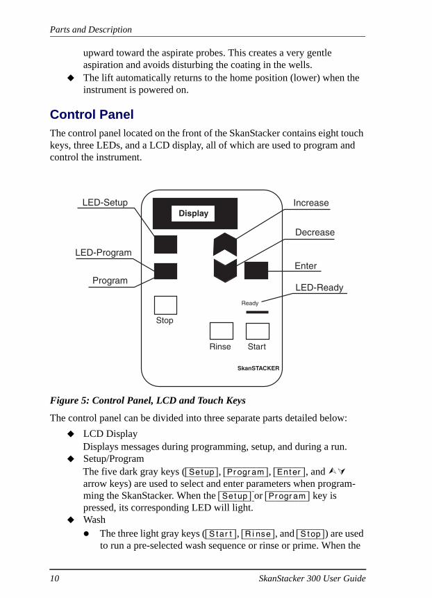
Control PanelThe control panel located on the front of the SkanStacker contains eight touch keys, three LEDs, and a LCD display, all of which are used to program and control the instrument.
Figure 5: Control Panel, LCD and Touch Keys
The control panel can be divided into three separate parts detailed below:LCD DisplayDisplays messages during programming, setup, and during a run.Setup/ProgramThe five dark gray keys ([Setup], [Program], [Enter], and arrow keys) are used to select and enter parameters when program-ming the SkanStacker. When the [Setup] or [Program] key is pressed, its corresponding LED will light.Wash
The three light gray keys ([Start], [Rinse], and [Stop]) are used to run a pre-selected wash sequence or rinse or prime. When the
SkanSTACKER
Ready
Stop
Display
StartRinse
LED-Setup
LED-Program
Increase
Decrease
Enter
LED-ReadyProgram
10 SkanStacker 300 User Guide

Parts and Description
SkanStacker is ready for wash, the Ready LED light turns on.The [Stop] key is used to halt operation in the event of a prob-lem.
Press the [Stop] key to interrupt current operation, and the LCD will display a stop message.Press the [Stop] key a second time to return to the main menu. (The microplate lift will move down to home posi-tion.)
LED DisplayThere are three LEDs that light up indicating various functions:Setup: LED will light when user is in setup mode.Program: LED will light when user is in program mode.Ready: LED will light when unit is ready to run a program.
Instrument Rear Connections
Figure 6: Rear of the SkanStacker
SkanStacker 300 User Guide 11

Parts and Description
Part Description
Inlet ports Located on the left side of the unit’s wash head. Two reser-voir containers can be connected to the Inlet and Rinse ports. Two 4 L reservoir bottles are provided with the sys-tem to accommodate a buffer (blue color-coded tubing) and rinse (green color-coded tubing) solution.
Vacuum port Located on the left side of the unit. The waste collection reservoir is connected to this port via the waste tubing (red color-coded). It is recommended to use the waste collec-tion vessel that is provided with the system.
Pressure ports
Located on the left side of the unit. The pressure tubing (yellow color-coded) is connected to these ports from the buffer and rinse reservoir bottle.
Main power Located on the back panel of the unit. This contains the main power receptacle, which includes the power switch and fuses (1 amp for 230 VAC/ 2 amp for 115 VAC). The selected voltage setting (110-130 VAC or 220-240 VAC) will point toward the white arrow. System includes either one power cable to handle 110 V or two power cables to handle 220 V, which includes a power cable for the UK. Consult Chapter 2: Installation for directions to change fuses and/or voltage setting.
Waste alarm connector
Located on the back panel of the unit. The waste alarm cable is connected to this port.
Microplate magazines
The instrument is equipped with two (2) microplate maga-zines that can process up to 25 microplates. A plastic clip at the bottom of the magazine holds the microplates in the magazine. The clips are activated by the microplate carrier during microplate collection and storage operations.
12 SkanStacker 300 User Guide

Parts and Description
Pressure/Vacuum Washer Parts
External Vacuum SourceThe instrument requires an external vacuum source. Vacuum is expressed in millibar (mbar), with reference to absolute vacuum, which equals 0 mbar, and room pressure, which equals 1000 mbar. (Note: 1000 mbar = 1 bar = 1 atmo-sphere = approximately 14 PSI). The instrument should be used with a stable vacuum source with the following minimum requirements:
Capacity: Higher than 30 L/min, free air displacement.Peak vacuum: Better than 300 mbar.
A dedicated vacuum source is recommended. House vacuum often has fluctu-ation in vacuum since typically there is more than one user.
Hydrophobic FilterA hydrophobic filter should be placed between the waste reservoir and vac-uum pump. The filter is used to protect the pump by preventing liquid from entering into the pump system. A filter with a pore size of 0.2 µm is recom-mended. Continuous use of the pump protection membrane filter will cause reduced flow capacity. The filter should be replaced when condensation is vis-ible in its housing.
Internal Pressure SourceThe instrument is equipped with an internal pressure pump that creates air pressure in the liquid reservoirs, eliminating the need for gravity feed. The pressure level can be adjusted between 0.0 and 0.6 bar (approximately 9 psi). The air pressure is supplied through the small quick couplings on the left side of the instrument labeled Pressure ports (Figure 2). The default air pressure value is 0.25 bar (approximately 4 psi). Any value between 0.15 -0.40 bar is considered a reasonable operating pressure. The air pressure value can be set for each wash program through the on-board software and adjusted for differ-ent assays.
TIP: Adjusting the level of the air pressure also adjusts the flow rate of the liquid entering the microplate wells. It does not have an effect on the volume.
SkanStacker 300 User Guide 13


Software Configuration
Chapter 4: Software Configuration
The SkanStacker allows up to eight different user-defined and programmed wash sequences to be stored in memory with a battery backup. Each wash program has the following options:
Air pressure from the internal pressure pump can be varied to control inlet liquid flow.Volume adjustment conversion factor, σV, can be used to fine-tune the dispense volume to adjust for the different viscosities of various liquids.The position (height) of the aspirate probe above the bottom of the well during aspiration can be varied. The amount of fluid kept in the well can be adjusted.Dispense probe height position in the well during washing can be set. Up to 16 wash sequence steps can be selected. Each step can be one of the following:
Aspirate, time in seconds [2–10 sec.]Wash, time in seconds [0.1–10 sec.]Wash, volume in µl [100–900 µl]Dispense, volume in µl [100–350 µl]Wash from inlet Rinse, time in seconds [0.1–10 sec.]Soak/pause, time in minutes and seconds [1 sec.–2 min 50 sec.]
The washer is pre-programmed with four typical wash sequences. These may be removed or changed as necessary.At the end of this Guide, a blank program guide sheet is included to facilitate programming. Duplicate this sheet for your own use to save a hard copy of each program for reference purposes.
SkanStacker 300 User Guide 14

Software Configuration
Setup FunctionThe [Setup] key is used to enter and leave the Setup window. When in Setup mode, the [Setup] key is used to move backward.
If an error occurs, press the [Setup] key to go back a step.The [Enter] key is used to select an item in a list or a value.The arrow keys are used to place the cursor on an item in a list or to scroll through values. To continue to scroll through values, keep the arrow key depressed.
When pressing the [Setup] key, the Setup Main menu will display two options:Edit Program A wash program can be edited or created using this selection.Edit Options Instrument parameters can be viewed and sensor enabled/
disabled.
Edit ProgramStep 1 Press [Setup] to enter the Setup window. The Setup LED will illu-
minate.
Step 2 Select Edit Program.Use arrow keys to move cursor to selection.Press [Enter].
Step 3 Select the program to be edited or select an open space to create a new wash program.
Use the arrow keys to move cursor to selection.Press [Enter].
!! IMPORTANT: To save changes, Exit/Save must be selected after program setting completed.
15 SkanStacker 300 User Guide

Software Configuration
Program Configuration Description
Exit/Save Use to exit program. User able to save or reject data before exiting.
Name Program name selected up to 5 characters. Select each character by using the arrow keys.Press [Enter] to move to the next character position.Characters can be capital or lower-case letters, digits, or special characters such as brackets, asterisks, colons, etc.Delete program by moving arrow key to blank space.
Air Pressure Pressure set for internal air pressure pump.Set to any value from 0.0 to 0.6 bar (approximately 9 psi).Pressure is changed to adjust the inlet wash liquid flow.To disable the pressure pump, select 0.0 bar.For normal wash, select 0.25 bar (approximately 4 psi).
Volume Adjust Adjustment can be made to fine tune the dispensed vol-ume using dispense or wash functions. The instrument is set at a default of 1.00 which can handle water and up to 0.02% Tween. If a viscous material is used, increase the
dispense volume by increasing the factor (range 0.01 to 2.50).
SkanStacker 300 User Guide 16

Software Configuration
Stacker Mode The processing routine between the wash head and the magazines can be selected.
Wash Only: Microplates are collected from the left magazine, washed, and stored in the right magazine.Restack Only: Microplates are collected from the left magazine and moved to the right magazine. No washing performed.Restack and Wash: Microplates are collected from the left magazine and stacked into the right magazine. Washing is performed on all plates from the right magazine and restacked into the left magazine.Wash and Restack: Microplates are collected from the left magazine, washed, and stored in the right magazine. When all plates are processed, the microplates will be restacked to their original position in the left magazine.
Set Wash Place microplate in left magazine and press [Enter]. Carriage will move microplate under probes. Use arrow keys to adjust probe position in wells. Adjust-ments made from left to right from a range of +/- 4.1 mm.
Set Aspirate Position
The position of the aspirate probe (longer probe) is adjusted using this setting.
This position is the height above the bottom of the well during aspiration.Place microplate in left magazine and press [Enter]. Carriage will move microplate under probes. Use arrow keys to set at correct height (see Figure 7).For low residual volume, the aspirate probe must be close to the bottom of the well. Total adjustable distance is 6 mm.
Program Configuration Description
17 SkanStacker 300 User Guide

Software Configuration
Set Dispense Position
The position of the dispense probes (shorter probes) is adjusted using this setting.
Place microplate in left magazine and press [Enter]. Carriage will move microplate under probes. Use arrow keys to set at correct height (see Figure 8).Total adjustable distance is 6 mm.
Wash Program 1-16
Up to 16 wash steps can be added. There are seven wash step selections available for each step: Rinse time, Disp volume, Soak / Pause, Wash volume, Wash time, Aspi-rate, and End Wash. See Table 1 on page 20 for descrip-tions.
Program Configuration Description
SkanStacker 300 User Guide 18

Software Configuration
Figure 7: Aspirate probe height position
Figure 8: Dispense probe height position
h = 0-6 mm
200 L0 L
h = 0-6 mm
19 SkanStacker 300 User Guide

Software Configuration
Wash Step Selections
Each program can have up to 16 wash steps. There are seven wash step selections available for each step. Press [Enter] to enter selection, and use arrow keys to change settings. Press [Enter] to select.
Wash Step Description
Rinse Time Set time in seconds from 0.1 to 10 seconds. Liquid will be dispensed from “Rinse” port. Fluid is agitated during rinse.
Disp Volume Set dispense volume from 100-350 µl. Liquid will be dispensed from “Inlet” port.
Soak/Pause Set soak/pause time from 5 seconds to 2 minutes 50 seconds.
Wash volume Set volume of wash from 100-900 µl. Liquid will be dis-pensed from “Inlet” port.
Wash time Set wash time from 0.1 to 10 seconds. Liquid will be dis-pensed from “Inlet” port. Fluid is agitated during wash.
Aspirate Set aspiration time from 2.0 - 10 seconds. Lift velocity is varied with selected aspirate time. The lift velocity is automatically set so that at the last second of the aspira-tion, the aspirate probes are at the bottom of the well. Aspirate times longer than 5 seconds will have the same lift velocity as the 5-second setting.Aspirate time = 2.0 seconds, lift velocity approximately 1 second.Aspirate time = 5 seconds, lift velocity approximately 4 seconds.
End Wash Set for last step of wash.
Table 1: Wash Step Selections
!! IMPORTANT: To save changes, Exit/Save must be selected after program setting completed.
SkanStacker 300 User Guide 20

Software Configuration
Save ProgramStep 1 From Edit Program Menu press the Up arrow key and select Exit/
Save.
Step 2 Press [Enter].
Step 3 Press Up-arrow key to select Yes-Save at question Save made changes?
Step 4 Press [Enter].
Edit OptionsWhen selecting Edit Options from the Setup Main Menu, there are six options to choose:
Sensor On/OffRead SensorStacker Sensor (read only)Set Horizontal Left/Right Position (Set >0< R-mag)Set Prime/Rinse Left/Right Position (Set >l< P/R)Test Stacker
Sensor On/OffThe sensors can be enabled or disabled by selecting this option.Step 1 Press [Setup] on the Control Panel to enter the Setup Main Menu.
Step 2 Press Down-arrow key to select Edit Options.
Step 3 Press [Enter].
Step 4 Select Sensor On/Off by pressing [Enter].
Step 5 Use Up arrow key to select either Enabled or Disabled.
Step 6 Press [Enter].
!! IMPORTANT: Program will enter this save window if user attempts to exit without saving. If Setup key pressed to return to the Setup Main menu without saving, changes will not be stored in memory.
21 SkanStacker 300 User Guide

Software Configuration
When Sensor is enabled, the following parameters must be valid to start a wash:
Air pressure must be close to the selected value.A microplate must be on the microplate holder.The waste reservoir must not be full.Waste vacuum must be less than 0.9 bar.
Read SensorInstrument parameters can be verified using this Edit Option. Five sensor val-ues are displayed for read-only purposes. No changes can be made from this screen. The five sensor values are from the following readings
!! IMPORTANT: When sensors disabled, all four safety features will be disengaged.
Air Pressure Value is actual air pressure on internal pressure source displayed in bar. Changes can be made through software program. This sensor can be disabled through Edit Options/Sensor On/Off.
Vacuum Value is vacuum pressure from vacuum port, displayed in bar. No changes can be made through software pro-gram.
µP This sensor will display “*” instead of microplate lift 0-position. Refer to Read Stacker Sensors to obtain status of microplate sensor. This sensor can be disabled through Edit Options/Sensor On/Off.
PL This sensor will display “*” instead of the plate lift 0-position. Refer to Read Stacker Sensors to obtain status of plate lift.
WF Shows the status of the waste level sensor. Displays in (+) or (-). This sensor can be disabled through Edit Options/Sensor On/Off.
SkanStacker 300 User Guide 22

Software Configuration
Read Stacker SensorsThis function is mainly for service personnel. A display of (+) will indicate the sensor is activated; a display of (-) will indicate optical sensor is not acti-vated. There are four optical sensors.
Checks status of horizontal movement sensor. Carriage is located in the correct position below the right magazine. Displays in (+) or (-).Checks status of vertical movement sensor. The vertical lift is located in the lowest position. Displays in (+) or (-).Checks release of movement sensor of release arms on the plate carriage. Displays in (+) or (-).Checks status of microplate sensor. Senses microplate in microplate holder. Displays in (+) or (-).
Set >0< R-mag (Horizontal Left/Right Position)This function is used to adjust the magazines to the center of the plate carriage platform. Changes will affect dispense position in all user programs.
Set >1< P/R (Prime/Rinse Left/Right Position)Adjustment can be made to the position of the wash probes during the Prime/Rinse function. Place microplate in left magazine. Press [Enter] to move plate under probes. Use arrow key to adjust probes in wells. Range -4.1 to +4.1 mm.
Test StackerThis function to be used by approved Technical Service Representative. After stacker tested, complete reset of the memory may be necessary resulting in programs reverting back to default factory settings. There are six positions that are tested as well as status of the four optical sensors.1. Horizontal to Wash Position2. Horizontal to Right Magazine Position3. Vertical to Up Position4. Veridical to Down Position5. Rel to In Position 6. Rel to Out Position
23 SkanStacker 300 User Guide

Operation
Chapter 5: OperationStarting a Wash Program Step 1 Edit or create wash program using the Edit Program through Setup
Main Menu.
Step 2 Verify appropriate liquid is in reservoir bottle.
Step 3 Verify connections.Verify reservoir bottles are connected to Inlet and Rinse port and pressurized.Verify waste bottle is connected to Waste port.
Step 4 Prime system.Place sample microplate in the left magazine.Press [Rinse] button to enter prime program.Press [Start].
Prime program will prime both Rinse and Inlet channels.Repeat 3 times.
Step 5 Choose Wash Program.Press Program key from control panel (Program LED will illumi-nate).Select a Wash program using the Arrow keys to move cursor to previously created/edited program.Press [Enter].
TIP: Program mode can be entered only when system is Ready (Ready LED will illuminate).If system is in Setup menu, press [Setup] key to return to Main Menu.To exit the Program mode with-out selecting a program, press the [Program] key.Use 0.02% Tween (i.e. 0.8 mL in 4L bottle) in wash solution to optimize surface tension and pre-vent dripping of probes.
SkanStacker 300 User Guide 24

Operation
Step 6 Place microplate(s) in the left magazine.
Step 7 Press [Start] key.
Step 8 When all microplates are washed, LED Ready light will illuminate.
Step 9 At end of run, run a rinse program using rinse solution (consult Daily Maintenance).
25 SkanStacker 300 User Guide

Maintenance
Chapter 6: MaintenanceDaily MaintenanceRun daily maintenance (Rinse program) at the end of each run and end of day. Decontaminate the instrument, externally and internally, after using infectious materials in the instrument. Commercially available laboratory decontami-nants may be used. Follow the manufacturer's directions for proper use.
Step 1 Verify rinse inlet and pressure tubing are connected between the instrument and rinse reservoir bottle (distilled water).
Step 2 Verify waste tubing is connected to vacuum port on instrument.
Step 3 Insert a clean microplate into the left magazine.
Step 4 Press the [Rinse] key to enter the Rinse/Prime mode.
Step 5 Press the [Rinse] key a second time to start the rinse program.The rinse program will rinse for 5 seconds and then soak the probe tips for 5 seconds. This cycle is repeated 3 times. Press Stop to reset the microplate carriage to its home position under the right magazine.
Step 6 If end of the day, proceed with Empty Wash Head Procedure.OrIf further washing will be performed later the same day, turn instru-ment off and start new wash with prime.
CAUTION: Consult chemical resistance chart to verify that decontaminant solution will not harm materials used in the design of the washer.
TIP: When the Rinse program is completed, the probes will be left soaking in liquid. If there is a pause in washing of more than 30 minutes, run this program to prevent sedimentation in the probes.
CAUTION: Do not leave probes soaking overnight. At end of day, empty wash head.
SkanStacker 300 User Guide 26

Maintenance
Empty Wash Head ProcedureDaily maintenance should be performed to remove any buffer from the lines. This will prevent crystallization of salts in the probes or wash head. Rinse sys-tem with 20% ETOH solution to deter bacterial and fungal contamination. Follow ETOH solution with a rinse with water. If the unit will not be used for more than a few days, empty the wash head by performing a reverse flush.
Step 1 Verify Daily Maintenance performed.Always run the rinse program prior to emptying the wash head.
Step 2 Disable sensors.Go to Setup Main Menu, select Edit Options, choose Sensor On/Off.Disable sensors.
Step 3 Disconnect the waste, inlet, and rinse tubing from the instrument.
Step 4 Verify waste tubing is connected to vacuum port and vacuum pump is on.
Step 5 Insert an empty microplate into the left magazine.
Step 6 Backflush the wash head through Inlet portStart Prime program.
Press the [Rinse] key to enter the Rinse/Prime mode.Press the [Start] key to start the prime program. (This will blow air through the wash head to remove any remaining liq-uid.)
Move waste tubing from vacuum port to Inlet port just prior to dispensing.Repeat 2 times.
Step 7 Backflush the wash head through Rinse portStart Rinse program.
Press the [Rinse] key to enter the Rinse/Prime mode.Press the [Rinse] key a second time to start the rinse pro-gram. (This will blow air through the wash head to remove any remaining liquid.)
Move waste tubing from vacuum port to Rinse port just prior to dispensing.Repeat 2 times.Reconnect waste tubing back to vacuum port.
27 SkanStacker 300 User Guide

Maintenance
Step 8 Reconnect tubing.Reconnect waste tubing to vacuum port.Reconnect liquid and pressure tubing to correct ports.
Step 9 Enable sensors.Go to Setup Main Menu, select Edit Options, choose Sensor On/Off.Enable sensors.
Step 10 Instrument may be turned off.
!! IMPORTANT: Prime instrument at next day of use with buffer solution. Follow instructions in Operation chapter.
SkanStacker 300 User Guide 28

Maintenance
Weekly MaintenancePerform maintenance once a week or after use of a contaminated solution in instrument to decontaminate system as well as clean probes.
Step 1 Perform Daily Maintenance to rinse system.
Step 2 Fill a reservoir bottle with 2% bleach solution or other decontami-nant solution (20–70% ETOH or an alkali solution of 5–10% NaOH are acceptable).
Step 3 Connect reservoir bottle to instrument.Replace Rinse reservoir bottle with bottle filled with decontami-nate solution. Connect tubing from reservoir bottle to Rinse port and pressure tubing to pressure port.Verify waste tubing is connected to vacuum port and vacuum pump.
Step 4 Insert a clean microplate into the left magazine.
CAUTION: Consult chemical resistance chart to verify that decontaminant solution will not harm materials used in the design of the washer. Solution that should be avoided: most acids, acetone, anilin, benzene, phosphoric acid, sulfuric acid, xylene, toulene, styrene, and pyridine.
!! IMPORTANT: Perform Daily Maintenance before running a decontaminant solution through instrument to rinse out all buffer products.
29 SkanStacker 300 User Guide

Maintenance
Step 5 Start Rinse program.Press the [Rinse] key to enter the Rinse/Prime mode.Press the [Rinse] key a second time to start the rinse program.(The rinse program will rinse for 5 seconds and then soak the probe tips for 5 seconds. This cycle is repeated 3 times.)
Step 6 Soak Probes.Press [Stop] key to pause when instrument is in first soak cycle of Rinse program.Let probes sit 5 minutes in decontaminant solution.Continue Rinse program by pressing [Rinse] key twice.
Step 7 Replace Rinse reservoir bottle with reservoir bottle filled with dis-tilled water.
Step 8 Start Rinse program.Press the [Rinse] key to enter the Rinse/Prime mode.Press the [Rinse] key a second time to start the rinse program.(The rinse program will rinse for 5 seconds and then soak the probe tips for 5 seconds. This cycle is repeated 3 times.)
Step 9 Repeat Rinse program 3 times.
Step 10 If end of the day, proceed with Empty Wash Head Procedure.
Monthly MaintenanceCheck hydrophobic protection filter located between vacuum pump and waste collection vessel.
Perform Adjusting vacuum pump procedure with and without fil-ter. If any difference in time between these two readings, change hydrophobic filter.
Check tubing and quick connects for wear and contamination. Replace if indicated.Check reservoir bottles.
Clean reservoir bottles with decontaminate solution. Flush well with water.Check reservoir bottles for contamination (algae). Replace if indi-cated.
SkanStacker 300 User Guide 30

Maintenance
Advanced Maintenance
Dispense testStep 1 Set up program for dispense test using the following parameters:
Aspirate 2 secWash 350 µlAspirate 2 secDispense 350 µlEND
Step 2 Prime system.
Step 3 Run program and inspect dispense levels; note any low volumes.
Step 4 Repeat 3 times.
Step 5 Inspect each well and note if any wells have lower volumes. If low volume consistent with all three dispenses, well must be cleared. Follow procedure for Clogged Probes. If inconsistent and lower vol-ume has occurred on any of the three dispenses, perform an Empty Head Procedure for a reverse flush of wash head.
Clogged Probes Probes have the potential of being clogged by small particles from the wash liquid, crystallization, or protein build-up. It is important to perform Daily and Weekly maintenance to keep probes free of debris.Step 1 Perform Daily Maintenance to rinse system.
Step 2 Perform Weekly Maintenance to clean probes.
Step 3 Clear particles from probes.Identify which probe is clogged.Use a probe wire to clear the probe.
Step 4 Replace Rinse reservoir bottle with reservoir bottle filled with dis-tilled water.
Step 5 Verify waste tubing is connected to vacuum port and pump is on.
Step 6 Perform a forward flush to remove the particles.Insert a clean microplate into the left magazine.Press the [Rinse] key to enter the Rinse/Prime mode.Press the [Start] key a second time to start the prime program.Repeat 3 times.
31 SkanStacker 300 User Guide

Maintenance
Step 7 Run a wash program to verify that particles are removed.
Step 8 If particles not removed, consult Technical Support.
Removal of wash headStep 1 Perform Empty Wash Head Procedure to drain wash head.
Step 2 Turn instrument off.
Step 3 Unscrew the wash head locking screws (2).
Step 4 Lift the wash head up slowly. Disconnect the air pressure supply tube and the ribbon cable from the wash head.
Figure 9: Wash head connections
Solenoid valves
Sensor block
Ribbon cable
Air pressure supply
SkanStacker 300 User Guide 32

Maintenance
Replacing ProbesIndividual probes can be replaced if identified to be the sole problem. Step 1 Identify if aspirate or dispense probe is to be replaced.
Inlet Probe used for dispense probe (part #1700-0190, pkg. 10/box).Outlet Probe used for aspirate probe (part #1700-0239, pkg. 10/box).
Step 2 Pull out probe with pliers.Remove old glue particles from wash head.
Step 3 Insert new probe, burr diameter = 1.10 mm.Apply Loctite Activator no.7649 on the mounting area on the probe. Push probe in until it is the same length as surrounding probes.
Step 4 Apply glue around probe at the point of entry at the wash headCommercially available glue recommended: Loctite QuickTite Super Glue Easy Squeeze Gel or Loctite 290 Loctite Threadlocker Green (does not set up as quickly as QuickTite).
Step 5 After 15 minutes, use water to wash excess glue off wash head.
33 SkanStacker 300 User Guide

Troubleshooting
Chapter 7: Troubleshooting
Troubleshooting ChartIf you experience a problem during operation of the SkanStacker and don’t know how to resolve it, the following table may prove helpful. Table 2 below lists problems and possible resolutions. For problems not listed here, or if the listed resolution does not fix the problem, please call the Technical Support department at Molecular Devices at 800-635-5577 (outside the U.S. and Can-ada, please contact your local representative for assistance).
Table 2: Troubleshooting Chart
Problem Possible Remedies
No power to instru-ment; instrument will not turn on
Check that power cord is plugged in.Check power supply.Check voltage selection switch.Check fuses (consult Chapter2: Installation).
Air in lines Prime lines: increase air pressure to 0.5 bar, then press [Rinse] and [Start].
Uneven aspiration Clean probes.Check spacing between ends of probes and bot-tom of wells.Adjust microplate alignment if indicated (see page 39).
Coating in wells is damaged after wash.
Reduce peak vacuum with the regulator on the vacuum pump.Increase the aspirate times to keep low residual volumes in the well.Adjust aspiration probe height in wells. Keep away from the bottom of the wells.Decrease air pressure to prevent damage during dispensing.Decrease number of wash steps.
SkanStacker 300 User Guide 34

Troubleshooting
Dripping from aspira-tion probes
Increase aspiration time.Check valves.Verify instrument level on counter.Verify vacuum tubing free from restrictions or obstructions.
Clogged aspiration probes
Use wire probe cleaner.Soak probes overnight in DI water.Consult Clogged Probe procedure.
Uneven dispenses Perform Clogged Probe procedure.Increase air pressure.
Magazine clip won’t hold microplate in place.
Check plastic magazine clip for wear. Replace if indicated.Magazine should be aligned over plate carriage platform. Consult Magazine Alignment proce-dure.
Dripping from dis-pense probes
Check for grime on probes. Perform Clogged Probe procedure.Check wash head. Prime system.Check amount of Tween, high percentage may cause dripping. Suggested to use <0.025% of Tween in wash fluid.
Programs not retained in instrument memory
Battery on main board may be low: battery life is from three to five years. Test the battery strength to see if it needs to be replaced. Strength should be 3.68 volts ± 5%. Replace battery with Lithium bat-tery ER6/3 6V. Replacement should be performed by a qualified service representative.
Pump continues to run
Remove tubing from side of washer at pressure fit-ting. If pump stops, the problem is probably the tubing caps. If the pump continues running, it is most likely another internal problem. Call Techni-cal Support.
Table 2: Troubleshooting Chart
Problem Possible Remedies
35 SkanStacker 300 User Guide

Troubleshooting
Plate carriage will not operate
Verify there is no obstruction on the plate carriage.
Plate dropping from magazine.
Check plastic magazine clip for wear. Replace if indicated.Magazine should be aligned over plate carriage platform. Consult Magazine Alignment proce-dure.
Carriage hitting the rail. Grinding sound heard after [Stop] button pressed.
Sensor for positioning plate carriage needs to be aligned. Call Technical Support.
Table 2: Troubleshooting Chart
Problem Possible Remedies
SkanStacker 300 User Guide 36
Troubleshooting
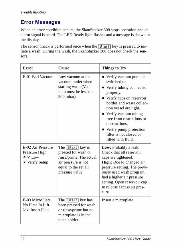
Error MessagesWhen an error condition occurs, the SkanStacker 300 stops operation and an alarm signal is heard. The LED Ready light flashes and a message is shown in the display.The sensor check is performed once when the [Start] key is pressed to ini-tiate a wash. During the wash, the SkanStacker 300 does not check the sen-sors.
Error Cause Things to Try
E-01 Bad Vacuum Low vacuum at the vacuum outlet when starting wash.(Vac-uum must be less than 900 mbar).
Verify vacuum pump is switched on. Verify tubing connected properly.Verify caps on reservoir bottles and waste collec-tion vessel are tight.Verify vacuum tubing free from restrictions or obstructions. Verify pump protection filter is not closed or filled with fluid.
E-02 Air PressurePressure High
Low Verify Setup
The [Start] key is pressed for wash or rinse/prime. The actual air pressure is not equal to the set air pressure value.
Low: Probably a leak. Check that all reservoir caps are tightened.High: Due to changed air pressure setting. The previ-ously used wash program had a higher air pressure setting. Open reservoir cap to release excess air pres-sure.
E-03 MicroPlateNo Plate In Lift
Insert Plate
The [Start] key has been pressed for wash or rinse/prime but no microplate is in the plate holder.
Insert a microplate.
37 SkanStacker 300 User Guide

Troubleshooting
E-04 Waste FullWaste Reservoir
Empty Waste
The [Start] key has been pressed for wash or rinse/prime, but the waste reservoir is full.
Empty the waste reser-voir to continue.Press the [Stop] key to return from the Error position.
E-08 Plate move-no store* Right mag >>Check Plate CarrORNo store* Left mag
Horizontal obstruction in plate path from magazines.(After plate washing, movement to right magazine failed.)
Verify correct micro-plate is in use.Verify microplate holder is in correct position. Alignment must be per-formed by Trained ser-vice Technician. Call Technical Support. Inspect magazine clip.Check horizontal posi-tion of the carriage through Setup Menu and Edit options (Set Hori-zontal >0< R-mag).
Error Cause Things to Try
SkanStacker 300 User Guide 38
Troubleshooting
Magazine AlignmentDetermine which magazine needs to be aligned over the plate carriage. Typi-cal symptom is magazine dropping microplates. If the right magazine needs alignment, proceed to Section A. If the left magazine needs alignment, pro-ceed to Section B.
Section A: Right magazine alignmentStep 1 Place empty magazines on platform.
Step 2 Test Horizontal Left/Right positioning through Edit Options.Press [Setup] on the Control Panel to enter the Setup Main Menu.Use arrow keys to move cursor to Edit Options.Press [Enter].Select >0< R-mag (Horizontal Left/Right positioning). Press[Enter] to move plate carriage platform under the right magazine and up to collect plate (no plate should be in the maga-zine at this time).
Step 3 Adjust left to right placement using arrow keys.
Step 4 Adjust magazine to center of plate carriage platform (see Figure 10).Loosen screws on top of the casing located to the right of the magazine. Loosen screws in the front and back of casing. Use screws to adjust the magazine to the center of the plate carriage platform (see Figure 10).When tightening the screw in back of casing, the magazine will move toward the back of instrument. When tightening the screw in the front of the casing, the maga-zine will move toward the front of the instrument.Tighten screw on the top of the casing.Press [Enter] to exit program.Press [Setup] [Setup] to return to main menu.
Step 5 Set up a program and test five microplates through the cycle of wash and restack. Re-adjust if indicated.
39 SkanStacker 300 User Guide

Troubleshooting
Figure 10: Right magazine alignment
Adjustment Screws
Balls Track
SkanStacker 300 User Guide 40

Troubleshooting
Section B: Left magazine alignmentStep 1 Place empty magazines on platform.
Step 2 Test Prime/Rinse positioning through Edit Options.Press [Setup] on the Control Panel to enter the Setup Main Menu.Use arrow keys to move cursor to Edit Options.Press [Enter].Select >1< P/R (Prime/Rinse positioning). Press [Enter] [Enter] to move plate carriage platform under the left magazine and up to collect plate (no plate should be in the magazine at this time).The plate carriage will go up to pick up plate; as it goes down, press [Stop].
Step 3 Adjust magazine to center of plate carriage platform (see Figure 10).Loosen screws on top of the casing located to the left of the mag-azine. Loosen screws in the front and back of casing. Use screws to adjust the magazine to the center of the plate carriage platform (see Figure 11).When tightening the screw in back of casing, the magazine will move toward the back of instrument. When tightening the screw in the front of the casing, the maga-zine will move toward the front of the instrument.Tighten screw on the top of the casing.Press [Stop] to reset.Press [Setup] [Setup] to return to main menu.
Step 4 Set up a program and test five microplates through the cycle of wash and restack. Re-adjust if indicated.
41 SkanStacker 300 User Guide

Troubleshooting
Figure 11: Left magazine alignment
Adjustment Screws
Balls Track
SkanStacker 300 User Guide 42

Troubleshooting
Vacuum Pump Troubleshooting
Adjusting vacuum pumpStep 1 Start pump with only the vacuum line inserted to pump.
If hydrophobic filter installed, make sure the ventilation hole is covered. Turn manometer clockwise to close the regulator. Start the pump. Air should be flowing freely and the manometer should read 950-1000 mbar.
Step 2 Close vacuum tubing by putting your finger over the opening. Vac-uum should reach a level of 50-100 mbar.
Step 3 Open manometer regulator screw about half a turn. The peak vac-uum will be reduced a few millibars, but this prevents condensation in the pump.
Step 4 Connect the empty 15-L waste collection vessel to vacuum pump and washer.
Step 5 Test the vacuum system performance. Record the reading from the manometer at 30 seconds, 60 seconds, 120 seconds, and at 3-4 min-utes. The expected performance (+/- 10%) is as follows:
With a start value of 1000 mbar, reading after 30 seconds should be 500 mbar.With a start value of 1000 mbar, reading after 60 seconds should be 300 mbar.With a start value of 1000 mbar, reading after 120 seconds should be 200 mbar.With a start value of 1000 mbar, reading after a few minutes should be 100 mbar.
Step 6 Evaluate system if performance not met. Rule out leaks in the sys-tem and/or build-up of condensed particles in filter. Repeat test if indicated.
43 SkanStacker 300 User Guide

Troubleshooting
Discharge test for vacuum pumpStep 1 Turn vacuum pump on with all tubing attached to instrument. Run
pump between 50-150 mbar.
Step 2 Disconnect vacuum tubing from washer.
Step 3 Observe reading on vacuum pump manometer. Reading should drop to 950-1000 mbar in less than 10 seconds.
Step 4 If test failed, check for obstruction.
Compare pump with internal vacuum sensorStep 1 Go to Setup Menu/Edit Options/Read Sensor.
Step 2 Record the internal vacuum sensor reading.
Step 3 Record the pump gauge reading.
Step 4 Compare two readings. If the readings are not the same, check for leaks or blockage in the vacuum system.
SkanStacker 300 User Guide 44

Troubleshooting
Application Tips: SkanWasher 300/ SkanStacker
Instrument FunctionsAir Pressure
Internal pressure pump creates air pressure within the liquid reservoir. Air pressure increases the flow rate and has no effect on volume. Increase the air pressure for higher pressure, decrease for lower pressure.Internal pressure pump adjusted through Edit Program through the Setup Menu.
Vacuum pressureVacuum pressure is regulated from pump gauge. Vacuum pressure determines the rate of aspiration. Increasing the vacuum pressure value decreases the vacuum.To convert mm Hg to mbar pressure, consult conversion table at web site: http://[email protected].
Suggested settingThese values are suggested as a starting point for your assay. Test between adjustments to optimize air and vacuum pressure for each specific assay.
External Software Setting
Applications
Vacuum pressure setting at pump
Air Pressure Range 0.0-0.6 bar (Edit Program)
Set Aspirate Position Range 0-6 mm (Edit Program)
ELISA and adherent cells
250 mbar 0.25 bar 0-2 mm (0=bottom of
plate)
Cells 350 mbar 0.15-0.20 bar 2-4 mm
45 SkanStacker 300 User Guide

Troubleshooting
Troubleshooting Tips
Problem Things to Try
Cells are aspirated off the bottom of the wells.
Decrease vacuum pressure at pump by increasing value. Optimize cell assay with vacuum pressure of 350-450 mbar.
Cells are being disrupted during dispens-ing. Lower air pressure by decreasing air pressure value in software through Edit Program.
Check Aspirate position in Edit Program from the Setup Menu in the software. Re-set height of aspiration probes. For low residual volume, the aspirate probe must be close to the bottom of the well.
Check Dispense position in Edit Program from the Setup Menu in the software. Re-set height of dispense probes.
Residual volume too high or low.
Check vacuum pressure. Pressure setting of 250 mbar is suggested for ELISA appli-cations. Increasing the value decreases the vacuum pressure, which slows the aspira-tion rate. Use a slower aspiration rate when working with cells.
Check Aspirate position in Edit Program from the Setup Menu in the software. Re-set height of aspiration probes. For low residual volume, the aspirate probe must be close to the bottom and side of the well.
If residual volume too low, check also for clogged probes. Is volume low in certain wells?
SkanStacker 300 User Guide 46


Appendix A: Shipment
Prior to transporting the SkanStacker, carry out the following steps. Step 1 Decontaminate the system following Weekly Maintenance proce-
dure. If radioactive materials are used, use appropriate decontami-nate solution for each material.
Step 2 Perform Empty Head procedure to empty dispense head of all fluid.
Step 3 Clean exterior surface of instrument with alcohol followed by water.
Step 4 Remove the magazines.
Step 5 Secure the wash head and plate carriage using foam and tape. Install transport bracket on rail (see page 5).
Step 6 Complete and sign the decontamination form.
Step 7 Ship in the original packaging material and cardboard box.
!! IMPORTANT: Original packaging must be used. If unavailable, obtain packaging from Molecular Devices.
SkanStacker User Manual A-1


Appendix B: Specifications
PhysicalDimensions
Length . . . . . . . . . . . . . . . . . 66 cmWidth. . . . . . . . . . . . . . . . . . 34 cmHeight . . . . . . . . . . . . . . . . . 58 cm
Weight . . . . . . . . . . . . . . . . . . . . 19 kgShipping weight. . . . . . . . . . . 35.5 kgShipping dimensions . . . . . . . 88 cm (L) x 48 CM (W) x 96 cm (H)Power source . . . . . . . . . . . . . . . 110/230 VAC ± 10%, 50/60 HzSetup memory . . . . . . . . . . . . . . Lithium battery, 8 wash programs +
instrument parametersPumps . . . . . . . . . . . . . . . . . . . . Internal pressure pumpFuse . . . . . . . . . . . . . . . . . . . . . . Two 2 amp, slow blow (110V)
Two 1 amp, slow blow (230V)Internal pressure . . . . . . . . . . . . Membrane air pump, 0-600 mbar
Electronic regulationMicroplate carriage . . . . . . . . . . Step motor drivenMagazine capacity . . . . . . . . . . . 25 microplates
PerformanceAspirate . . . . . . . . . . . . . . . . . . . < 5 µl average residual volume/wellDispense
Accuracy . . . . . . . . . . . . . . . < 4% CV at 350 µlVolume . . . . . . . . . . . . . . . . 100-350 µl
Internal volume . . . . . . . . . . . . . Wash head prime volume < 35 mLWell flow rate (Room temperature water and 0.2% Tween)
At air pressure 0.25 bar . . . . Typical flow rate 260 µl/sAt air pressure 0.50 bar . . . . Typical flow rate 430 µl/s
ChemicalHousing . . . . . . . . . . . . . . . . . . . Painted, marine-grade aluminumMicroplate magazines . . . . . . . . Anodized, marine-grade aluminumWash elements . . . . . . . . . . . . . . Stainless steel probesWash head . . . . . . . . . . . . . . . . . PVCValve . . . . . . . . . . . . . . . . . . . . . Viton-membrane, solenoid operatedInlet/outlet/pressure ports . . . . . Polypropylene quick disconnect,
Viton O-rings
SkanStacker User Guide B-2


Appendix C: WarrantyMolecular Devices Corporation warrants this product against defects in mate-rial or workmanship as follows:
All parts of the SkanStacker are warranted for a period of one(1) year from the original date of delivery.All labor charges to repair the product for a period of one (1) year from the original date of delivery will be paid by Molecular Devices Corporation. This warranty covers the SkanStacker system only and does not extend to any computer, printer, reagents, disposables, or additional software used with this system.
Labor and PartsTo obtain warranty service during the applicable warranty period, you must take the product or deliver the product properly packaged in the original ship-ping materials and carton to an authorized Molecular Devices Corporation service facility. You must call or write to the nearest Molecular Devices Cor-poration service facility to schedule warranty service. You may call Molecular Devices Corporation at the telephone number or address below to locate the nearest service facility. At the time of requesting warranty service, you must present proof of purchase documentation which includes the date of purchase, and Molecular Devices Corporation must have the Warranty Registration form completed, signed, and returned by you within ten (10) working days of the date of delivery. This warranty covers only defects arising under normal usage and does not cover malfunctions or failures from misuse, abuse, neglect, alter-ations, modifications, or repairs by other than an authorized Molecular Devices Corporation service facility.Repair or replacement as provided under this warranty is the exclusive rem-edy to the purchaser (the “Buyer”). Molecular Devices Corporation (the “Seller”) shall not be liable for any incidental or consequential damages for breach of any express or implied warranty on this product, except to the extent required by applicable law. The Seller specifically excludes all express and implies warranties including without limitation any implied warranty that the products sold under this agreement are merchantable or are fit for any particu-lar purpose, except such warranties expressly identified as warranties and set forth for any particular purpose, except such warranties expressly identified as warranties and set forth in the Seller’s current user guide, catalog, or written guarantee covering such product. The Seller also makes no warranty that the
SkanStacker User Guide C-3
Appendix C: Warranty
products sold under this agreement are delivered free of the rightful claim of any third party by way of patent infringement or the like. If the Buyer fur-nishes specifications to the Seller, the Buyer agrees to hold the Seller harmless against any claim that arises out of compliance with the specifications. Any description of the products contained in this agreement is for the sole purpose of identifying them. Any such description is not part of the basis of the bargain and does not constitute a warranty that the products shall conform to that description. Any sample or model used in connection with this agree-ment is for illustrative purposes only, is not part of the basis of the bargain, and is not to be construed as a warranty that the products will conform to the sample or model. No affirmation of fact or promise made by the Seller, whether or not in this agreement, shall constitute a warranty that the products will conform to the affirmation or the promise.For the name of the nearest authorized Molecular Devices Corporation ser-vice facility, please contact Molecular Devices at one of the following tele-phone numbers:408-747-1700800-735-5577 (US & Canada)
C-4 SkanStacker User Guide

Appendix D: Wash Program Sheets
SkanStacker 300 Wash Program SheetProgram 1Wash programs are pre-set at the factory. These programs may be edited.
Instrument Parameters
Wash Sequence
Program Number 1 Program Name A + 3 * W
Date 09.10.1998 Signature /TB
Description: Demo programWash: Aspirate followed by 3 times wash.Stacker: Wash Only–microplates will be in right magazine when ready.Note: Adjust probe position before using program.
Stacker Mode Wash Only Wash & ReStack ReStack & Wash ReStack Only Air Pressure 0.25 [bar] Volume Adjust σV 1.00 [-]Wash | Probe [mm] Aspirate Probe [mm]Dispense Probe [mm] Hor 0 position 0.0 [mm]
1. Wash Step Aspirate Wash Dispense Soak Rinse 2.0 sec/____ µl
2. Wash Step Aspirate Wash Dispense Soak Rinse 1.5 sec/____ µl
3. Wash Step Aspirate Wash Dispense Soak Rinse 2.0 sec/____ µl
4. Wash Step Aspirate Wash Dispense Soak Rinse 1.5 sec/____ µl
5. Wash Step Aspirate Wash Dispense Soak Rinse 2.0 sec/____ µl
6. Wash Step Aspirate Wash Dispense Soak Rinse 1.5 sec/____ µl
7. Wash Step Aspirate Wash Dispense Soak Rinse 4.0 sec/____ µl
8. Wash Step Aspirate Wash Dispense Soak Rinse _____ sec/____ µl
9. Wash Step Aspirate Wash Dispense Soak Rinse _____ sec/____ µl
10. Wash Step Aspirate Wash Dispense Soak Rinse _____ sec/____ µl
11. Wash Step Aspirate Wash Dispense Soak Rinse _____ sec/____ µl
12. Wash Step Aspirate Wash Dispense Soak Rinse _____ sec/____ µl
13. Wash Step Aspirate Wash Dispense Soak Rinse _____ sec/____ µl
14. Wash Step Aspirate Wash Dispense Soak Rinse _____ sec/____ µl
15. Wash Step Aspirate Wash Dispense Soak Rinse _____ sec/____ µl
16. Wash Step Aspirate Wash Dispense Soak Rinse _____ sec/____ µl
SkanStacker 300 User Guide D-5
Appendix D: Wash Program Sheets
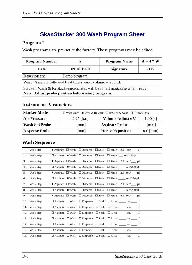
SkanStacker 300 Wash Program SheetProgram 2Wash programs are pre-set at the factory. These programs may be edited.
Instrument Parameters
Wash Sequence
Program Number 2 Program Name A + 4 * W
Date 09.10.1998 Signature /TB
Description: Demo programWash: Aspirate followed by 4 times wash volume = 250 µL.Stacker: Wash & ReStack–microplates will be in left magazine when ready.Note: Adjust probe position before using program.
Stacker Mode Wash Only Wash & ReStack ReStack & Wash ReStack Only Air Pressure 0.25 [bar] Volume Adjust σV 1.00 [-]Wash | Probe [mm] Aspirate Probe [mm]Dispense Probe [mm] Hor 0 position 0.0 [mm]
1. Wash Step Aspirate Wash Dispense Soak Rinse 2.0 sec/____ µl
2. Wash Step Aspirate Wash Dispense Soak Rinse sec/ 250 µl
3. Wash Step Aspirate Wash Dispense Soak Rinse 2.0 sec/____ µl
4. Wash Step Aspirate Wash Dispense Soak Rinse _____ sec/ 250 µl
5. Wash Step Aspirate Wash Dispense Soak Rinse 2.0 sec/____ µl
6. Wash Step Aspirate Wash Dispense Soak Rinse _____ sec/ 250 µl
7. Wash Step Aspirate Wash Dispense Soak Rinse 2.0 sec/____ µl
8. Wash Step Aspirate Wash Dispense Soak Rinse _____ sec/ 250 µl
9. Wash Step Aspirate Wash Dispense Soak Rinse 4.0 sec/____ µl
10. Wash Step Aspirate Wash Dispense Soak Rinse _____ sec/____ µl
11. Wash Step Aspirate Wash Dispense Soak Rinse _____ sec/____ µl
12. Wash Step Aspirate Wash Dispense Soak Rinse _____ sec/____ µl
13. Wash Step Aspirate Wash Dispense Soak Rinse _____ sec/____ µl
14. Wash Step Aspirate Wash Dispense Soak Rinse _____ sec/____ µl
15. Wash Step Aspirate Wash Dispense Soak Rinse _____ sec/____ µl
16. Wash Step Aspirate Wash Dispense Soak Rinse _____ sec/____ µl
D-6 SkanStacker 300 User Guide

Appendix D: Wash Program Sheets
SkanStacker 300 Wash Program SheetProgram 3Wash programs are pre-set at the factory. These programs may be edited.
Instrument Parameters
Wash Sequence
Program Number 3 Program Name A 2 W S A
Date 09.10.1998 Signature /TB
Description: Demo wash programWash: Aspirate followed by 2 times wash, soak for 5 seconds then finally an
aspirate.Stacker: ReStack & Wash –microplates will be in left magazine when ready.Note: Adjust probe position before using program.
Stacker Mode Wash Only Wash & ReStack ReStack & Wash ReStack Only Air Pressure 0.25 [bar] Volume Adjust σV 1.00 [-]Wash | Probe [mm] Aspirate Probe [mm]Dispense Probe [mm] Hor 0 position 0.0 [mm]
1. Wash Step Aspirate Wash Dispense Soak Rinse 2.0 sec/____ µl
2. Wash Step Aspirate Wash Dispense Soak Rinse 1.0 sec/____ µl
3. Wash Step Aspirate Wash Dispense Soak Rinse 2.0 sec/____ µl
4. Wash Step Aspirate Wash Dispense Soak Rinse _____ sec/ 200 µl
5. Wash Step Aspirate Wash Dispense Soak Rinse 5.0 sec/____ µl
6. Wash Step Aspirate Wash Dispense Soak Rinse 4.0 sec/____ µl
7. Wash Step Aspirate Wash Dispense Soak Rinse _____ sec/____ µl
8. Wash Step Aspirate Wash Dispense Soak Rinse _____ sec/____ µl
9. Wash Step Aspirate Wash Dispense Soak Rinse _____ sec/____ µl
10. Wash Step Aspirate Wash Dispense Soak Rinse _____ sec/____ µl
11. Wash Step Aspirate Wash Dispense Soak Rinse _____ sec/____ µl
12. Wash Step Aspirate Wash Dispense Soak Rinse _____ sec/____ µl
13. Wash Step Aspirate Wash Dispense Soak Rinse _____ sec/____ µl
14. Wash Step Aspirate Wash Dispense Soak Rinse _____ sec/____ µl
15. Wash Step Aspirate Wash Dispense Soak Rinse _____ sec/____ µl
16. Wash Step Aspirate Wash Dispense Soak Rinse _____ sec/____ µl
SkanStacker 300 User Guide D-7

Appendix D: Wash Program Sheets
SkanStacker 300 Wash Program SheetProgram 4Wash programs are pre-set at the factory. These programs may be edited.
Instrument Parameters
Wash Sequence
Program Number 4 Program Name D - V 2 5
Date 09.10.1998 Signature /TB
Description: Demo wash programAspirate followed by Dispense 200 µL.Stacker: Wash & ReStack–microplates will be in left magazine when ready.Note: Adjust probe position before using program.
Stacker Mode Wash Only Wash & ReStack ReStack & Wash ReStack Only Air Pressure 0.25 [bar] Volume Adjust σV 1.00 [-]Wash | Probe [mm] Aspirate Probe [mm]Dispense Probe [mm] Hor 0 position 0.0 [mm]
1. Wash Step Aspirate Wash Dispense Soak Rinse 2.0 sec/____ µl
2. Wash Step Aspirate Wash Dispense Soak Rinse _____ sec/ 200 µl
3. Wash Step Aspirate Wash Dispense Soak Rinse _____ sec/____ µl
4. Wash Step Aspirate Wash Dispense Soak Rinse _____ sec/____ µl
5. Wash Step Aspirate Wash Dispense Soak Rinse _____ sec/____ µl
6. Wash Step Aspirate Wash Dispense Soak Rinse _____ sec/____ µl
7. Wash Step Aspirate Wash Dispense Soak Rinse _____ sec/____ µl
8. Wash Step Aspirate Wash Dispense Soak Rinse _____ sec/____ µl
9. Wash Step Aspirate Wash Dispense Soak Rinse _____ sec/____ µl
10. Wash Step Aspirate Wash Dispense Soak Rinse _____ sec/____ µl
11. Wash Step Aspirate Wash Dispense Soak Rinse _____ sec/____ µl
12. Wash Step Aspirate Wash Dispense Soak Rinse _____ sec/____ µl
13. Wash Step Aspirate Wash Dispense Soak Rinse _____ sec/____ µl
14. Wash Step Aspirate Wash Dispense Soak Rinse _____ sec/____ µl
15. Wash Step Aspirate Wash Dispense Soak Rinse _____ sec/____ µl
16. Wash Step Aspirate Wash Dispense Soak Rinse _____ sec/____ µl
D-8 SkanStacker 300 User Guide

Appendix D: Wash Program Sheets
SkanStacker 300 Wash Program SheetProgram 5Wash programs are pre-set at the factory. These programs may be edited.
Instrument Parameters
Wash Sequence
Program Number 5 Program Name D - V 5 0
Date 09.10.1998 Signature /TB
Description: Demo wash programAspirate followed by Dispense 200 µL.Stacker: Wash Only–microplates will be in right magazine when ready.Note: Adjust probe position before using program.
Stacker Mode Wash Only Wash & ReStack ReStack & Wash ReStack Only Air Pressure 0.25 [bar] Volume Adjust σV 1.00 [-]Wash | Probe [mm] Aspirate Probe [mm]Dispense Probe [mm] Hor 0 position 0.0 [mm]
1. Wash Step Aspirate Wash Dispense Soak Rinse 2.0 sec/____ µl
2. Wash Step Aspirate Wash Dispense Soak Rinse _____ sec/ 200 µl
3. Wash Step Aspirate Wash Dispense Soak Rinse _____ sec/____ µl
4. Wash Step Aspirate Wash Dispense Soak Rinse _____ sec/____ µl
5. Wash Step Aspirate Wash Dispense Soak Rinse _____ sec/____ µl
6. Wash Step Aspirate Wash Dispense Soak Rinse _____ sec/____ µl
7. Wash Step Aspirate Wash Dispense Soak Rinse _____ sec/____ µl
8. Wash Step Aspirate Wash Dispense Soak Rinse _____ sec/____ µl
9. Wash Step Aspirate Wash Dispense Soak Rinse _____ sec/____ µl
10. Wash Step Aspirate Wash Dispense Soak Rinse _____ sec/____ µl
11. Wash Step Aspirate Wash Dispense Soak Rinse _____ sec/____ µl
12. Wash Step Aspirate Wash Dispense Soak Rinse _____ sec/____ µl
13. Wash Step Aspirate Wash Dispense Soak Rinse _____ sec/____ µl
14. Wash Step Aspirate Wash Dispense Soak Rinse _____ sec/____ µl
15. Wash Step Aspirate Wash Dispense Soak Rinse _____ sec/____ µl
16. Wash Step Aspirate Wash Dispense Soak Rinse _____ sec/____ µl
SkanStacker 300 User Guide D-9

Appendix D: Wash Program Sheets
SkanStacker 300 Wash Program SheetProgram 6Wash programs are pre-set at the factory. These programs may be edited.
Instrument Parameters
Wash Sequence
Program Number 6 Program Name D + A S P
Date 09.10.1998 Signature /TB
Description: Demo wash programWash followed by Aspirate.Stacker: Wash Only–microplates will be in right magazine when ready.Note: Adjust probe position before using program.
Stacker Mode Wash Only Wash & ReStack ReStack & Wash ReStack Only Air Pressure 0.25 [bar] Volume Adjust σV 1.00 [-]Wash | Probe [mm] Aspirate Probe [mm]Dispense Probe [mm] Hor 0 position 0.0 [mm]
1. Wash Step Aspirate Wash Dispense Soak Rinse 3.0 sec/____ µl
2. Wash Step Aspirate Wash Dispense Soak Rinse 4.0 sec/____ µl
3. Wash Step Aspirate Wash Dispense Soak Rinse _____ sec/____ µl
4. Wash Step Aspirate Wash Dispense Soak Rinse _____ sec/____ µl
5. Wash Step Aspirate Wash Dispense Soak Rinse _____ sec/____ µl
6. Wash Step Aspirate Wash Dispense Soak Rinse _____ sec/____ µl
7. Wash Step Aspirate Wash Dispense Soak Rinse _____ sec/____ µl
8. Wash Step Aspirate Wash Dispense Soak Rinse _____ sec/____ µl
9. Wash Step Aspirate Wash Dispense Soak Rinse _____ sec/____ µl
10. Wash Step Aspirate Wash Dispense Soak Rinse _____ sec/____ µl
11. Wash Step Aspirate Wash Dispense Soak Rinse _____ sec/____ µl
12. Wash Step Aspirate Wash Dispense Soak Rinse _____ sec/____ µl
13. Wash Step Aspirate Wash Dispense Soak Rinse _____ sec/____ µl
14. Wash Step Aspirate Wash Dispense Soak Rinse _____ sec/____ µl
15. Wash Step Aspirate Wash Dispense Soak Rinse _____ sec/____ µl
16. Wash Step Aspirate Wash Dispense Soak Rinse _____ sec/____ µl
D-10 SkanStacker 300 User Guide

Appendix D: Wash Program Sheets
SkanStacker 300 Wash Program SheetProgram 7Wash programs are pre-set at the factory. These programs may be edited.
Instrument Parameters
Wash Sequence
Program Number 7 Program Name R E S T K
Date 09.10.1998 Signature /TB
Description: Demo wash programStacker: ReStack Only.
Stacker Mode Wash Only Wash & ReStack ReStack & Wash ReStack Only Air Pressure 0.25 [bar] Volume Adjust σV 1.00 [-]Wash | Probe [mm] Aspirate Probe [mm]Dispense Probe [mm] Hor 0 position 0.0 [mm]
1. Wash Step Aspirate Wash Dispense Soak Rinse 1.0 sec/____ µl
2. Wash Step Aspirate Wash Dispense Soak Rinse _____sec/____ µl
3. Wash Step Aspirate Wash Dispense Soak Rinse _____ sec/____ µl
4. Wash Step Aspirate Wash Dispense Soak Rinse _____ sec/____ µl
5. Wash Step Aspirate Wash Dispense Soak Rinse _____ sec/____ µl
6. Wash Step Aspirate Wash Dispense Soak Rinse _____ sec/____ µl
7. Wash Step Aspirate Wash Dispense Soak Rinse _____ sec/____ µl
8. Wash Step Aspirate Wash Dispense Soak Rinse _____ sec/____ µl
9. Wash Step Aspirate Wash Dispense Soak Rinse _____ sec/____ µl
10. Wash Step Aspirate Wash Dispense Soak Rinse _____ sec/____ µl
11. Wash Step Aspirate Wash Dispense Soak Rinse _____ sec/____ µl
12. Wash Step Aspirate Wash Dispense Soak Rinse _____ sec/____ µl
13. Wash Step Aspirate Wash Dispense Soak Rinse _____ sec/____ µl
14. Wash Step Aspirate Wash Dispense Soak Rinse _____ sec/____ µl
15. Wash Step Aspirate Wash Dispense Soak Rinse _____ sec/____ µl
16. Wash Step Aspirate Wash Dispense Soak Rinse _____ sec/____ µl
SkanStacker 300 User Guide D-11

Appendix D: Wash Program Sheets
SkanStacker 300 Wash Program Sheet
Instrument Parameters
Wash Sequence
Program Number Program Name
Date 09.10.1998 Signature
Description:
Stacker Mode Wash Only Wash & ReStack ReStack & Wash ReStack Only Air Pressure 0.25 [bar] Volume Adjust σV 1.00 [-]Wash | Probe [mm] Aspirate Probe [mm]Dispense Probe [mm] Hor 0 position 0.0 [mm]
1. Wash Step Aspirate Wash Dispense Soak Rinse _____ sec/____ µl
2. Wash Step Aspirate Wash Dispense Soak Rinse _____ sec/____ µl
3. Wash Step Aspirate Wash Dispense Soak Rinse _____ sec/____ µl
4. Wash Step Aspirate Wash Dispense Soak Rinse _____ sec/____ µl
5. Wash Step Aspirate Wash Dispense Soak Rinse _____ sec/____ µl
6. Wash Step Aspirate Wash Dispense Soak Rinse _____ sec/____ µl
7. Wash Step Aspirate Wash Dispense Soak Rinse _____ sec/____ µl
8. Wash Step Aspirate Wash Dispense Soak Rinse _____ sec/____ µl
9. Wash Step Aspirate Wash Dispense Soak Rinse _____ sec/____ µl
10. Wash Step Aspirate Wash Dispense Soak Rinse _____ sec/____ µl
11. Wash Step Aspirate Wash Dispense Soak Rinse _____ sec/____ µl
12. Wash Step Aspirate Wash Dispense Soak Rinse _____ sec/____ µl
13. Wash Step Aspirate Wash Dispense Soak Rinse _____ sec/____ µl
14. Wash Step Aspirate Wash Dispense Soak Rinse _____ sec/____ µl
15. Wash Step Aspirate Wash Dispense Soak Rinse _____ sec/____ µl
16. Wash Step Aspirate Wash Dispense Soak Rinse _____ sec/____ µl
D-12 SkanStacker 300 User Guide

Index
AAdvanced maintenance 31Alert symbols 2Application tips 45Application tips, troubleshooting 46Aspirate 10, 17, 20
CConnections 11Control panel 10
keysAspirate 10Enter 10Program 10Start 10Stop 10
DDaily maintenance 26Decontamination 26, 29Dispense 18
EEdit Options 15, 21Edit Program 15ELISA setting 45Empty Wash Head Procedure 27Enter (key) 10Error messages 37
FFilter for waste reservoir 6Filter, waste 13
HHome position (microplate lift) 10Hydrophobic filter 13
IInlet port 7, 12Installation 5
LLCD display 10LED display 11
MMagazine alignment 39– 42Main power 12Maintenance 26
advanced 31daily 26weekly 29
Memory 14Microplate lift 9
home position 10Microplate transfer base 8
OOperation 24
PPressure port 7, 12Pressure pump 13, 16Pressure, port from wash reservoir 7Probes
alignment 17, 18
SkanStacker 300 User Guide I-1

replacement 33Program (key) 10
RRead Sensor 22, 23Ready LED 11Replacing probes 33Rinse key 10Rinse port 7Rinse time 20
SSafety features 3Serial number 3Settings overview 1Setup function 15Setup key 10Shipment A-1Soak 20Software 14Specifications B-2Stacker mode 17Stacker sensors 23Stacker test 23Start (key) 10Stop (key) 10Stop key 11System contents 3
TTroubleshooting 34
advanced 37Tween 24
VVacuum port 6Vacuum pump 13, 43– 44, 45Voltage setting 5
Volume adjustment 16
WWarranty C-3Wash 10
inlet port 7rinse port 7
Wash head 9Wash head removal 32Wash parameters, overview 1Wash program 24Wash program sheets D-5Waste
alarm 6connecting the reservoir 6filter 6outlet port 6pressure port 7vacuum port 6
Waste alarm connector 12Weekly maintenance 29
I-2 SkanStacker 300 User Guide