skb/c electronic valve actuator - industry mall
TRANSCRIPT
Installation Instructions
Document No. 129-185 September 24, 2018
SKB/C Electronic Valve Actuator
Item Number: 129-185-05, Rev. CA Page 1 of 9
Product Description
The SKB/C actuators require a 24 Vac supply signal to control either a 3/4-inch (20 mm) or 1-1/2-inch (40 mm) stroke valve. These actuators work with Flowrite™ 599 Series valves with a 3/4-inch (20 mm) stroke (SKB) or a 1-1/2-inch (40 mm) stroke (SKC).
Product Numbers
SKBx 3/4-inch (20 mm) stroke SKCx 1-1/2-inch (40 mm) stroke
Warning/Caution Notations
WARNING:
Personal injury or loss of life may occur if you do not follow a procedure as specified.
CAUTION:
Equipment damage, or loss of data may occur you do not follow a procedure as specified.
Required Tools
• 24 mm open-end wrench
• 3/8-inch open-end wrench
• No. 1 Phillips or flat-blade screwdriver
• Small adjustable wrench
Expected Installation Time
20 minutes for factory-installed actuator 46 minutes for field replacement of actuator
Prerequisites
WARNING: If mounting the actuator to a valve already in line, either close the shut-off valves in the piping (upstream first, then downstream) or switch off the pump to allow the differential and static pressure in the valve to drop.
CAUTION: Do not damage or scratch the polished surface of the valve stem.
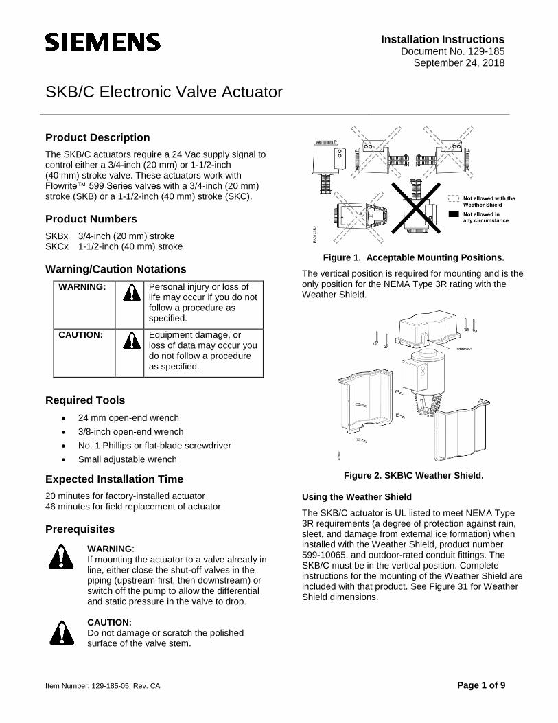
Figure 1. Acceptable Mounting Positions.
The vertical position is required for mounting and is the only position for the NEMA Type 3R rating with the Weather Shield.
Figure 2. SKB\C Weather Shield.
Using the Weather Shield
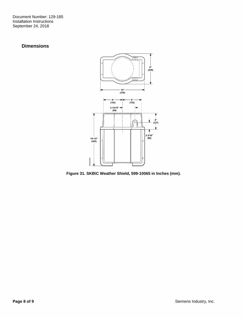
The SKB/C actuator is UL listed to meet NEMA Type 3R requirements (a degree of protection against rain, sleet, and damage from external ice formation) when installed with the Weather Shield, product number 599-10065, and outdoor-rated conduit fittings. The SKB/C must be in the vertical position. Complete instructions for the mounting of the Weather Shield are included with that product. See Figure 31 for Weather Shield dimensions.
Document Number: 129-185 Installation Instructions September 24, 2018
Page 2 of 9 Siemens Industry, Inc.
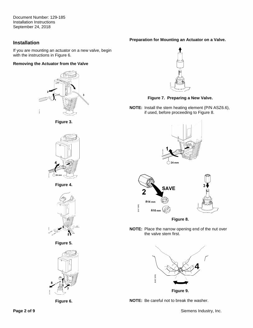
Installation
If you are mounting an actuator on a new valve, begin with the instructions in Figure 6.
Removing the Actuator from the Valve
Figure 3.
Figure 4.
Figure 5.
Figure 6.
Preparation for Mounting an Actuator on a Valve.
Figure 7. Preparing a New Valve.
NOTE: Install the stem heating element (P/N ASZ6.6), if used, before proceeding to Figure 8.
Figure 8.
NOTE: Place the narrow opening end of the nut over the valve stem first.
Figure 9.
NOTE: Be careful not to break the washer.
4
Document Number: 129-185 Installation Instructions
September 24, 2018
Siemens Industry, Inc. Page 3 of 9
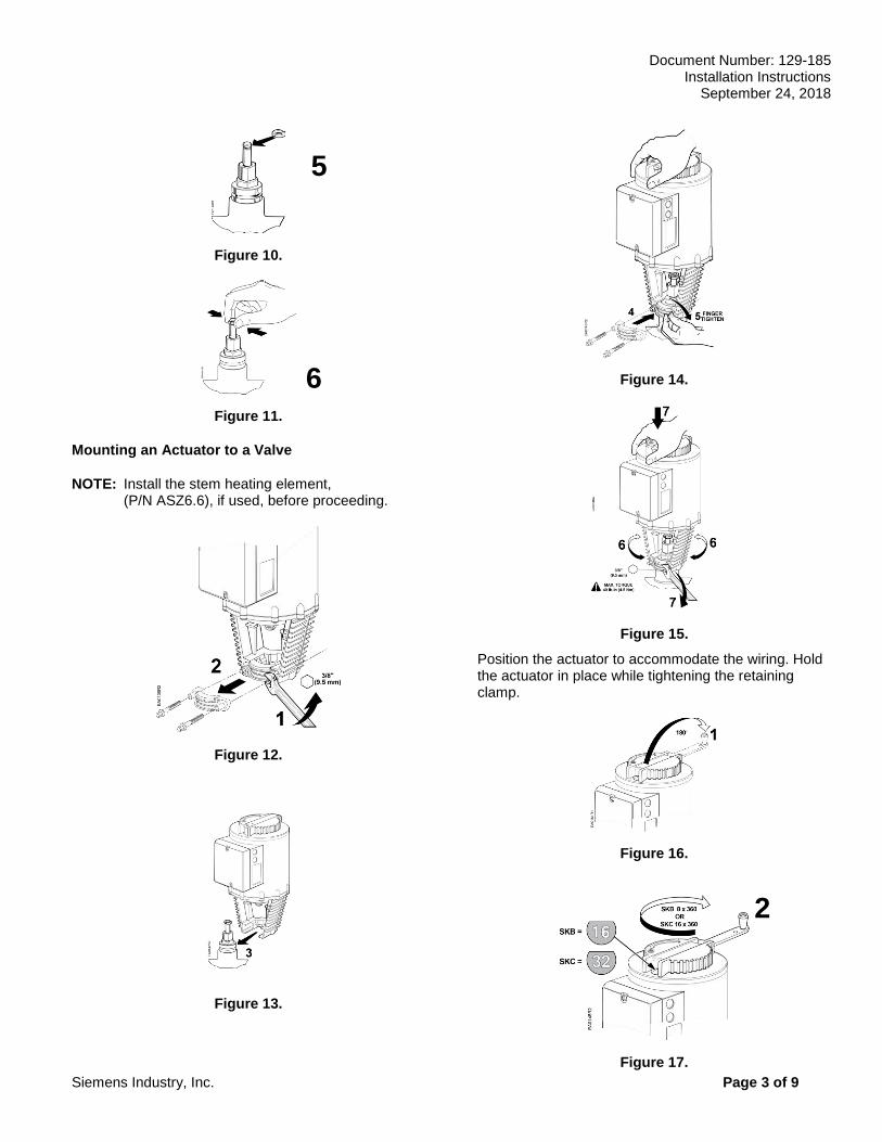
Figure 10.
Figure 11.
Mounting an Actuator to a Valve
NOTE: Install the stem heating element, (P/N ASZ6.6), if used, before proceeding.
Figure 12.
Figure 13.
Figure 14.
Figure 15.
Position the actuator to accommodate the wiring. Hold the actuator in place while tightening the retaining clamp.
Figure 16.
Figure 17.
2
5
6
Document Number: 129-185 Installation Instructions September 24, 2018
Page 4 of 9 Siemens Industry, Inc.
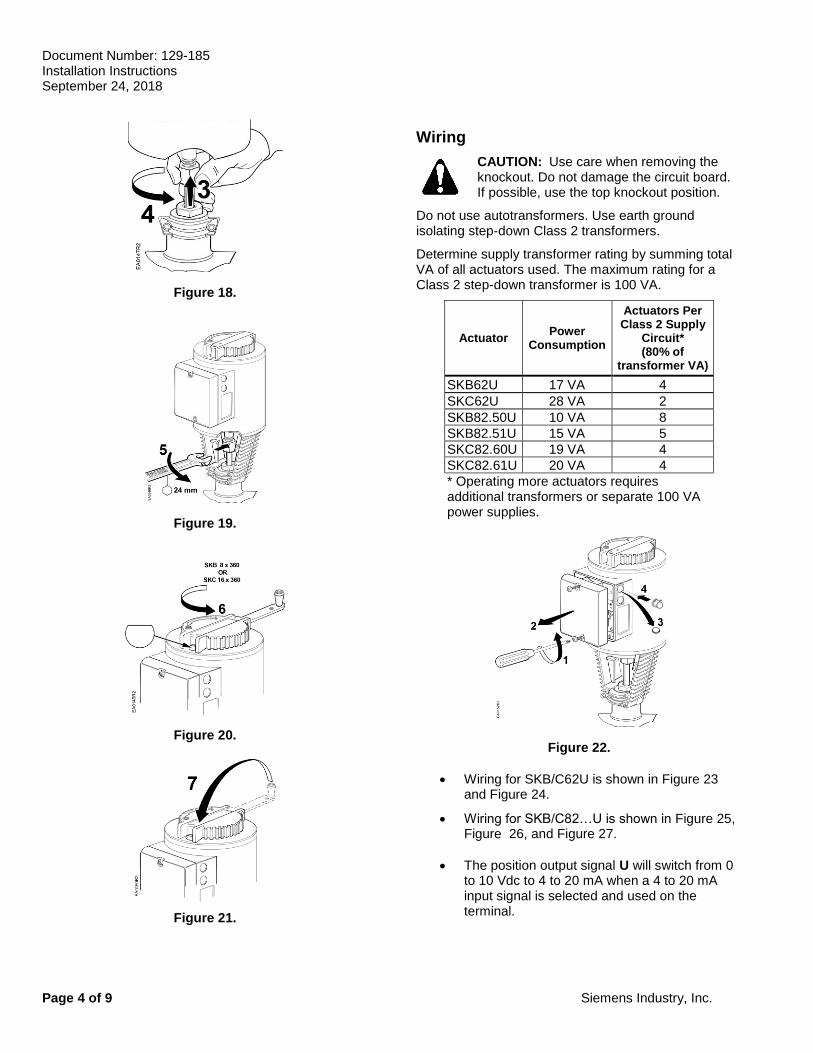
Figure 18.
Figure 19.
Figure 20.
Figure 21.
Wiring
CAUTION: Use care when removing the knockout. Do not damage the circuit board. If possible, use the top knockout position.
Do not use autotransformers. Use earth ground isolating step-down Class 2 transformers.
Determine supply transformer rating by summing total VA of all actuators used. The maximum rating for a Class 2 step-down transformer is 100 VA.
Actuator Power
Consumption
Actuators Per Class 2 Supply
Circuit* (80% of
transformer VA)
SKB62U 17 VA 4
SKC62U 28 VA 2
SKB82.50U 10 VA 8
SKB82.51U 15 VA 5
SKC82.60U 19 VA 4
SKC82.61U 20 VA 4
* Operating more actuators requires additional transformers or separate 100 VA power supplies.
Figure 22.
• Wiring for SKB/C62U is shown in Figure 23 and Figure 24.
• Wiring for SKB/C82…U is shown in Figure 25, Figure 26, and Figure 27.
• The position output signal U will switch from 0 to 10 Vdc to 4 to 20 mA when a 4 to 20 mA input signal is selected and used on the terminal.
Document Number: 129-185 Installation Instructions
September 24, 2018
Siemens Industry, Inc. Page 5 of 9
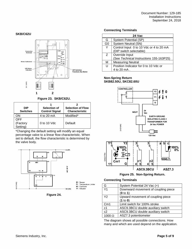
SKB/C62U
1 2
Figure 23. SKB/C62U.
DIP Switches
1 Selection of
Control Signal
2 Selection of Flow
Characteristic
ON 4 to 20 mA Modified*
OFF (Factory Setting)
0 to 10 Vdc Default
*Changing the default setting will modify an equal percentage valve to a linear flow characteristic. When set to default, the flow characteristic is determined by the valve body.
Figure 24.
Connecting Terminals
24 Vac
G System Potential (SP)
G0 System Neutral (SN)
Y Control Input 0 to 10 Vdc or 4 to 20 mA (DIP switch selectable)
Z Override Input (See Technical Instructions 155-163P25)
M Measuring Neutral
U Position Indicator for 0 to 10 Vdc or 4 to 20 mA .
Non-Spring Return SKB82.50U, SKC82.60U
Figure 25. Non-Spring Return.
Connecting Terminals
G System Potential 24 Vac (+)
Y1 Downward movement of coupling piece (0 to 1)
Y2 Upward movement of coupling piece (1 to 0)
Cm1 Limit switch for 100% stroke
c1 ASC9.3BCU double auxiliary switch
c2 ASC9.3BCU double auxiliary switch
1000 ASZ7.3 potentiometer
The diagram shows all possible connections. How many and which are used depend on the application.
Document Number: 129-185 Installation Instructions September 24, 2018
Page 6 of 9 Siemens Industry, Inc.
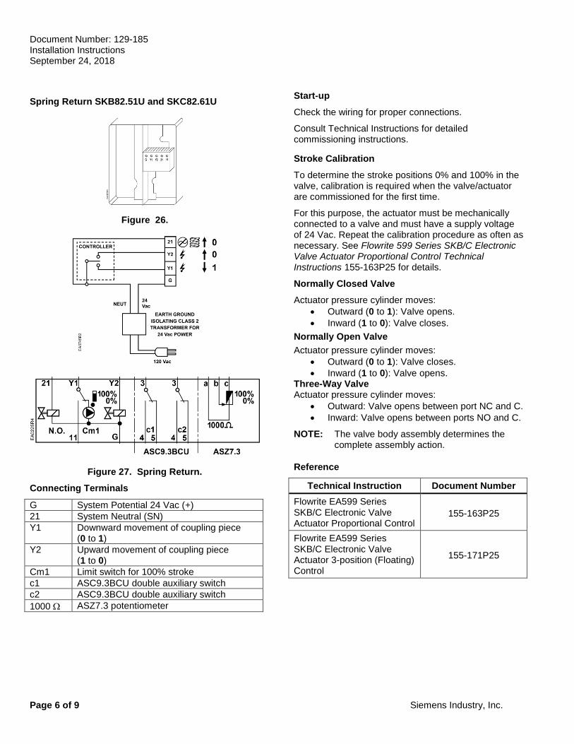
Spring Return SKB82.51U and SKC82.61U
Figure 26.
Figure 27. Spring Return.
Connecting Terminals
G System Potential 24 Vac (+)
21 System Neutral (SN)
Y1 Downward movement of coupling piece (0 to 1)
Y2 Upward movement of coupling piece (1 to 0)
Cm1 Limit switch for 100% stroke
c1 ASC9.3BCU double auxiliary switch
c2 ASC9.3BCU double auxiliary switch
1000 ASZ7.3 potentiometer
Start-up
Check the wiring for proper connections.
Consult Technical Instructions for detailed commissioning instructions.
Stroke Calibration
To determine the stroke positions 0% and 100% in the valve, calibration is required when the valve/actuator are commissioned for the first time.
For this purpose, the actuator must be mechanically connected to a valve and must have a supply voltage of 24 Vac. Repeat the calibration procedure as often as necessary. See Flowrite 599 Series SKB/C Electronic Valve Actuator Proportional Control Technical Instructions 155-163P25 for details.
Normally Closed Valve
Actuator pressure cylinder moves:
• Outward (0 to 1): Valve opens.
• Inward (1 to 0): Valve closes.
Normally Open Valve
Actuator pressure cylinder moves:
• Outward (0 to 1): Valve closes.
• Inward (1 to 0): Valve opens. Three-Way Valve Actuator pressure cylinder moves:
• Outward: Valve opens between port NC and C.
• Inward: Valve opens between ports NO and C.
NOTE: The valve body assembly determines the complete assembly action.
Reference
Technical Instruction Document Number
Flowrite EA599 Series SKB/C Electronic Valve Actuator Proportional Control
155-163P25
Flowrite EA599 Series SKB/C Electronic Valve Actuator 3-position (Floating) Control
155-171P25
Document Number: 129-185 Installation Instructions
September 24, 2018
Siemens Industry, Inc. Page 7 of 9
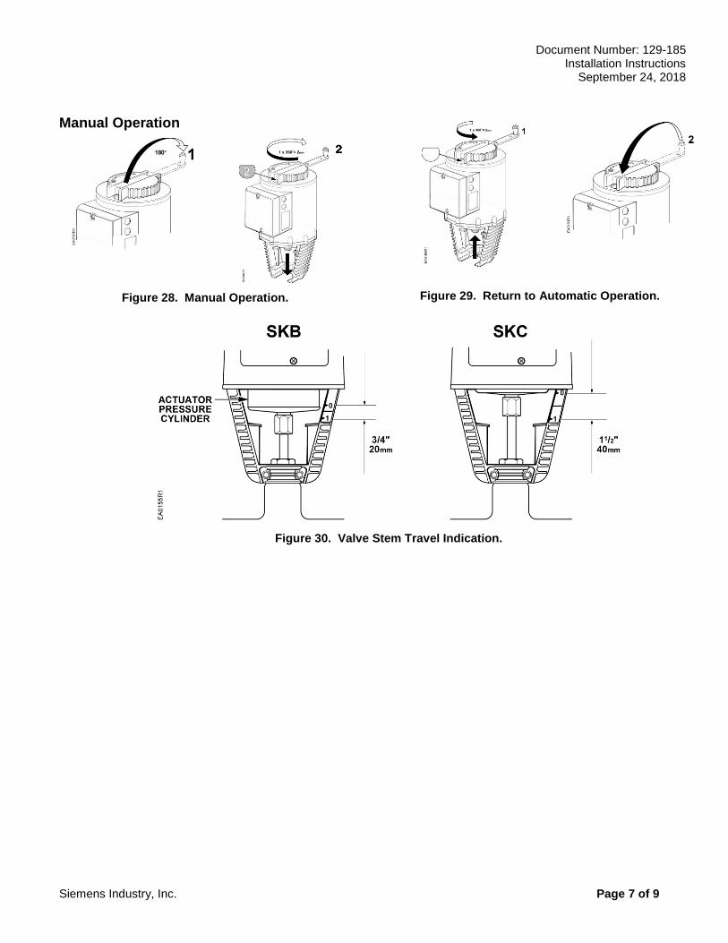
Manual Operation
Figure 28. Manual Operation.
Figure 29. Return to Automatic Operation.
Figure 30. Valve Stem Travel Indication.
Document Number: 129-185 Installation Instructions September 24, 2018
Page 8 of 9 Siemens Industry, Inc.
Dimensions
Figure 31. SKB\C Weather Shield, 599-10065 in Inches (mm).
Document Number: 129-185 Installation Instructions
September 24, 2018
Information in this publication is based on current specifications. The company reserves the right to make changes in specifications and models as design improvements are introduced. Other product or company names mentioned herein may be the trademarks of their respective owners. Flowrite is a trademark of Siemens Industry, Inc. © 2018 Siemens Industry, Inc.
Siemens Building Technologies, Inc. 1000 Deerfield Parkway Buffalo Grove, IL 60089-4513 USA
Your feedback is important to us. If you have comments about this document, please send them to [email protected]
Document No. 129-185 Printed in the USA.
Page 9 of 9
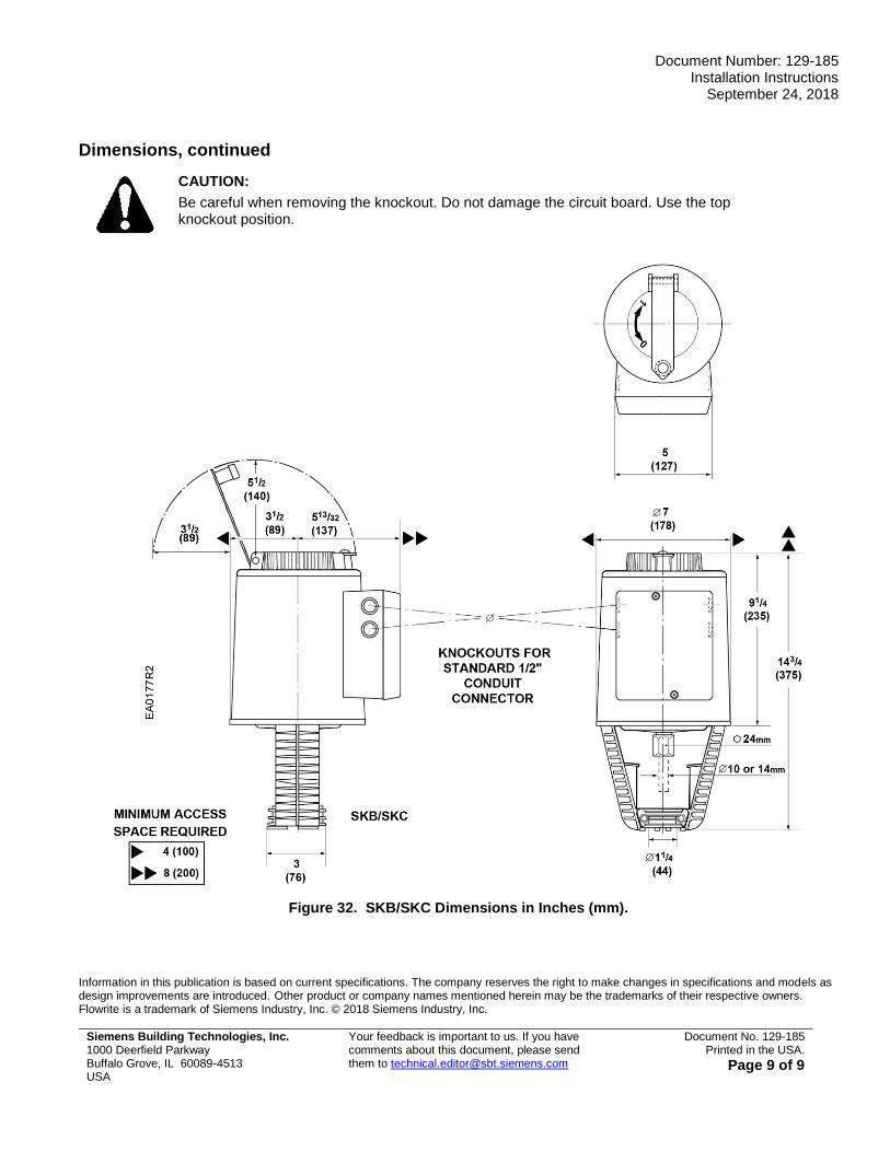
Dimensions, continued
CAUTION:
Be careful when removing the knockout. Do not damage the circuit board. Use the top knockout position.
Figure 32. SKB/SKC Dimensions in Inches (mm).