sketching and lettering arcs axis (axes) composition concentric circles ellipses gothic...
Post on 19-Dec-2015
288 views
TRANSCRIPT

Chapter 2-5 ReviewDrafting 2-4
Chapter 2Sketching and Lettering

VOCABULARY Arcs Axis (axes) Composition Concentric Circles Ellipses Gothic Lettering Guidelines Isometric Lines Isometric Sketching Lettering Line
Non- Isometric Lines Oblique Sketch Overlay Plane Point Proportion Radius (radii) Tangent arcs Texture
**** YOU SHOULD WRITE THESE DOWN and Define them.... Might be on a test!
The Design Process The Design Process

The Design Process The Design Process

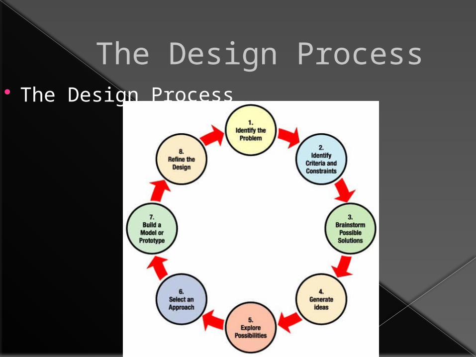
The Design Process STEP 1: Identify the Problem --
Students should state the challenge problem in their own words. Example: How can I design a __________ that will __________?

The Design Process The Design Process

The Design ProcessSTEP 2: Identify Criteria and Constraints --
Students should specify the design requirements (criteria).
Example: Our growth chamber must have a growing surface of 10 square feet and have a delivery volume of 3 cubic feet or less. Students should list the limits on the design due to available resources and the environment (constraints). Example: Our growth chamber must be accessible to astronauts without the need for leaving the spacecraft.
The Design Process The Design Process

The Design ProcessSTEP 3: Brainstorm Possible
Solutions -- Each student in the group should sketch his or her own ideas as the group discusses ways to solve the problem. Labels and arrows should be included to identify parts and how they might move. These drawings should be quick and brief.

The Design Process The Design Process
The Design ProcessSTEP 4: Generate Ideas -- In this step, each
student should develop two or three ideas more thoroughly. Students should create new drawings that are orthographic projections (multiple views showing the top, front and one side) and isometric drawings (three-dimensional depiction). These are to be drawn neatly, using rulers to draw straight lines and to make parts proportional. Parts and measurements should be labeled clearly.

The Design Process The Design Process

The Design ProcessSTEP 5: Explore Possibilities -- The
developed ideas should be shared and discussed among the team members. Students should record pros and cons of each design idea directly on the paper next to the drawings.

The Design Process The Design Process

The Design ProcessSTEP 6: Select an Approach --
Students should work in teams and identify the design that appears to solve the problem the best. Students should write a statement that describes why they chose the solution. This should include some reference to the criteria and constraints identified above.

Chapter 2 The Design Process

The Design ProcessSTEP 7: Build a Model or Prototype --
Students will construct a full-size or scale model based on their drawings. The teacher will help identify and acquire appropriate modeling materials and tools. See the design brief for a sample list.

The Design Process The Design Process

The Design ProcessSTEP 8: Refine the Design -- Students
will examine and evaluate their prototypes or designs based on the criteria and constraints. Groups may enlist students from other groups to review the solution and help identify changes that need to be made. Based on criteria and constraints, teams must identify any problems and proposed solutions.
OVERVIEW What is spatial visualization? Isometric Drawings Sketching Isometric Drawings Coded Plans Visualization of Object Viewpoints Examples
SPATIAL VISUALIZATION
The ability to mentally manipulate, rotate, twist, or invert a pictorially presented object.
Important skill for scientific & technical fields, such as:› Architects & Engineers› Doctors› Computer Programmers› Anyone needing a creative solution to a
problem

Reasons for Sketching Sketching is drawing freehand without
the aid of any drafting equipment except paper and pencil. It is a very common form of visual communication that is used in virtually ALL areas of work and life.

Cool thing about Sketching 1. Uses no drafting equipment - freehand 2. Is an extremely fast form of visual
communication. 3. Sketches increase clarity and understanding
of concepts, shapes, or directions. 4. Is very convenient - can be done anywhere. 5. Is an extremely valuable organizational tool,
which helps to minimize or prevent errors. 6. Is a collection of all necessary information
required about an object - including detail, size and shape descriptions.
Reasons for Sketching Critical Factors
› A. Key Reasons for Sketching 1) Communicate 2) Organize 3) Realize Ideas
› B. Key Factors while Sketching 1) Speed 2) Accuracy 3) Clarity
Drawing MethodsConstruction Lines to Object Lines
1) ALL single lines - NO "fuzzy" art type lines! 2) Point to Point 3) Dash to Dash 4) Draw Left to Right OR Bottom to Top B.
Drawing MethodsBlock Technique
1) Establish outer proportions of object(s) 2) Divide into areas of major shapes 3) Add detail as required 4) Add text where necessary to clarify (notes or dimensions)

Drawing MethodsGraph Technique (Resizing or Duplicating
an Original) 1) Use original photo or drawing OR a xerox copy. 2) Draw Horizontal & Vertical grid lines on top of object spaced an exact distance apart (ex. ½", ¼", etc.). 3) On clean sheet of paper reproduce grid at desired size (enlarge / reduce) 4) Add line detail a block at a time.

Types of Sketches One View Orthographic Projection
1) Always that view which would be considered the front of the object. 2) Used when only one view is necessary to provide shape description.
Types of SketchesTwo View Orthographic Projection
1) Front View and Top View. 2) Used for cylindrical objects when all side views are identical.

Types of SketchesThree View Orthographic Projection
1) Front View, Top View, and Right Side View 2) Provides the most complete shape and size description. 3) Is the industry standard for the manufacture of objects.

Types of SketchesEnlargement / Reduction (Templates)
1) Use of graph paper to enlarge or reduce grid size 2) Complete sketch square by square, comparing individual squares as you proceed.

Types of SketchesRealize Ideas / Designing
1) Front View, Top View, and Right Side View 2) Clarity is essential, use text notes whenever necessary. 3) Be sure finished sketch reflects what is in your mind.
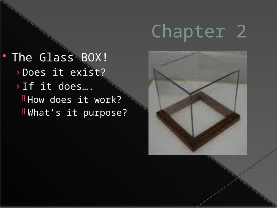
Chapter 2 The Glass BOX!
› Does it exist?› If it does…. How does it work? What’s it purpose?

Chapter 2 The Glass BOX!
› Does it exist? YES› If it does…. How does it work? You will see….on next slide What’s it purpose? TO Help one visualize all the views for an object.

Orthographic or Multiview Drawings
Imagine that you have an object suspended by transparent threads inside a glass box.

Orthographic or Multiview Drawings, Continued…
Then draw the object on each of three faces as seen from that direction. Unfold the box (figure 4) and you have the three views. We call this an "orthographic" or "multiview" drawing.
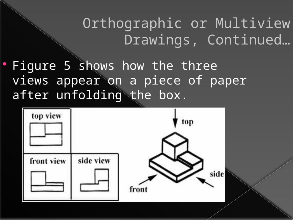
Orthographic or Multiview Drawings, Continued…
Figure 5 shows how the three views appear on a piece of paper after unfolding the box.

Orthographic or Multiview Drawings, Continued…
Which views should one choose for a multiview drawing?
The views that reveal every detail about the object. Three views are not always necessary; we need only as many views as are required to describe the object fully.
Orthographic or Multiview Drawings, Continued…
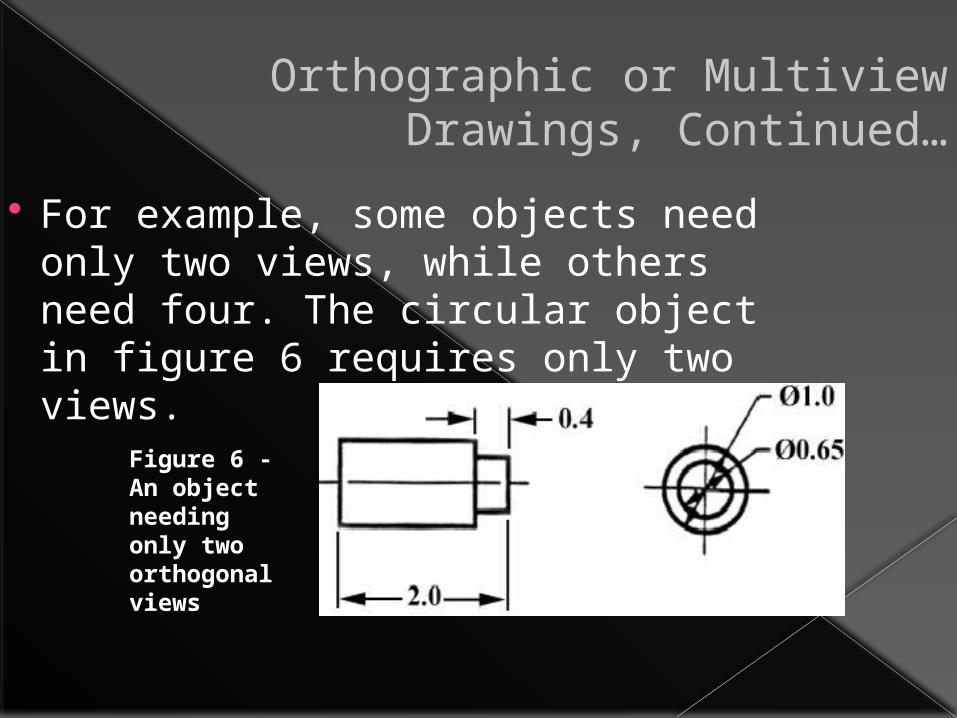
For example, some objects need only two views, while others need four. The circular object in figure 6 requires only two views.
Figure 6 - An object needing only two orthogonal views

To Review

ORTHOGRAPHIC PROJECTION Shows the faces of an object Faces are parallel to the viewing plane
› Frontal› Profile› Horizontal

VIEWING PLANES

FRONT VIEW

RIGHT SIDE VIEW
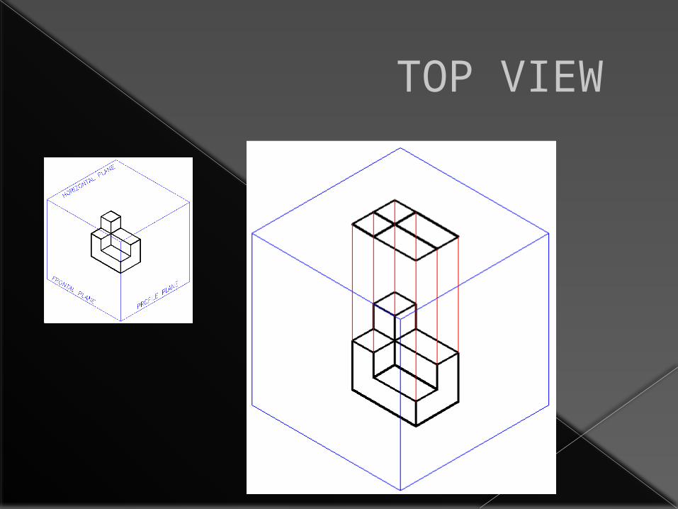
TOP VIEW

MULTIVIEW PROJECTION

UNFOLD THE BOX

ORTHOGRAPHIC PROJECTION

ORTHOGRAPHIC DRAWING
Front view shows height & width Side view shows height & depth Top view shows width & depth Visible edges are solid lines. Non-visible edges are dashed
(hidden) lines Views align with each other Rotation from one view to another
equals 90°
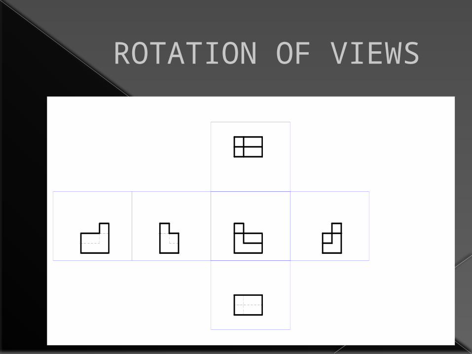
ROTATION OF VIEWS
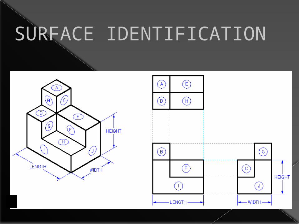
SURFACE IDENTIFICATION

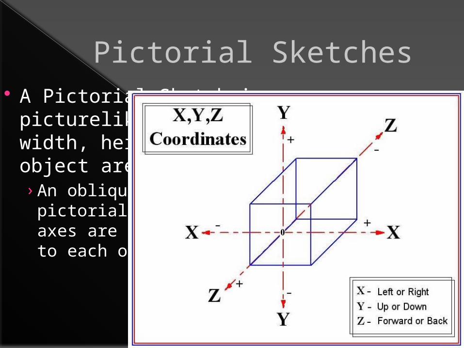
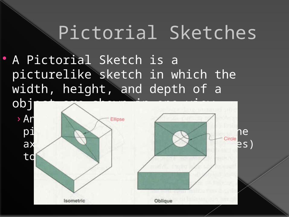
Pictorial Sketches A Pictorial Sketch is a picturelike sketch
in which the width, height, and depth of a object are shown in one view.

Pictorial Sketches A Pictorial Sketch is a picturelike sketch
in which the width, height, and depth of a object are shown in one view. › An oblique sketch is a type of pictorial
sketch in which two of the axes are at right angles (90 degrees) to each other.
Pictorial Sketches A Pictorial Sketch is a picturelike sketch
in which the width, height, and depth of a object are shown in one view. › An oblique sketch is a type of pictorial
sketch in which two of the axes are at right angles (90 degrees) to each other.

Pictorial Sketches A Pictorial Sketch is a picturelike sketch
in which the width, height, and depth of a object are shown in one view. › An oblique sketch is a type of pictorial sketch
in which two of the axes are at right angles (90 degrees) to each other.
› An isometric sketch is a type of pictorial sketch that relies on three axes to show width height and depth. However , an isometric sketch, shows the axes spaced equally. (120 degrees)
Pictorial Sketches A Pictorial Sketch is a picturelike sketch
in which the width, height, and depth of a object are shown in one view. › An oblique sketch is a type of pictorial
sketch in which two of the axes are at right angles (90 degrees) to each other.

ISOMETRIC DRAWINGS Used to show 3-Dimensional projection
on a 2-Dimensional surface. Projected so that width and length are
30° from horizontal and height is vertical.

Isometric Sketching

Isometric Sketching

Isometric Sketching

Isometric Sketching

CODED PLANS Shows height of each “cube” stack. Each corner could be a viewpoint of the
object. Viewpoint means the direction in which
an observer is viewing the object. Similar to a top view in an Orthographic
Projection.

VISUALIZE OBJECT2
1
1V
V = Viewpoint
V
FOR SKECTHING –
DO NOT SHOW EACH CUBE. SHOW ONLY VISIBLE SURFACES AND EDGES, AS IF CUBES HAVE BEEN COMBINED.

EXAMPLE #12
1
1V
V = Viewpoint
V
Note location of viewpoint and coded plan noting height of object. Click to start animation.

EXAMPLE #22
1
2
V
3
1
Click to start animation.

VIEWPOINT Viewpoints can make the object appear
differently. Example #2 is redrawn with a different
viewpoint.

DIFFERENT VIEWPOINT
2
1
2
V
3
1
Click to start animation.
COMPARISON OF VIEWPOINTS Different look Optical illusion of height Viewpoints can show or exclude details
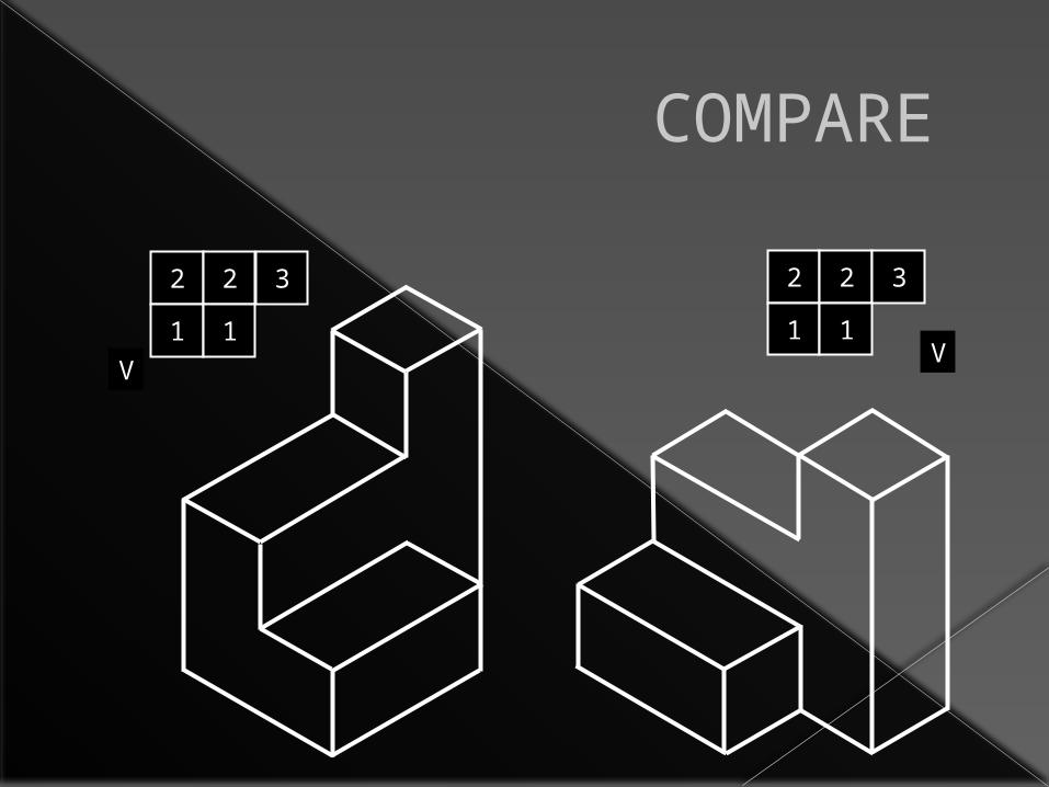
COMPARE
2
1
2
V
3
1
2
1
2
V
3
1

ORTHOGRAPHIC vs. ISOMETRIC
ISOMETRIC DRAWING ORTHOGRAPHIC DRAWING

CONCLUSION Spatial Visualization is an important skill Coded plans help you visualize a solid
object Viewpoints change look of object and
can hide details
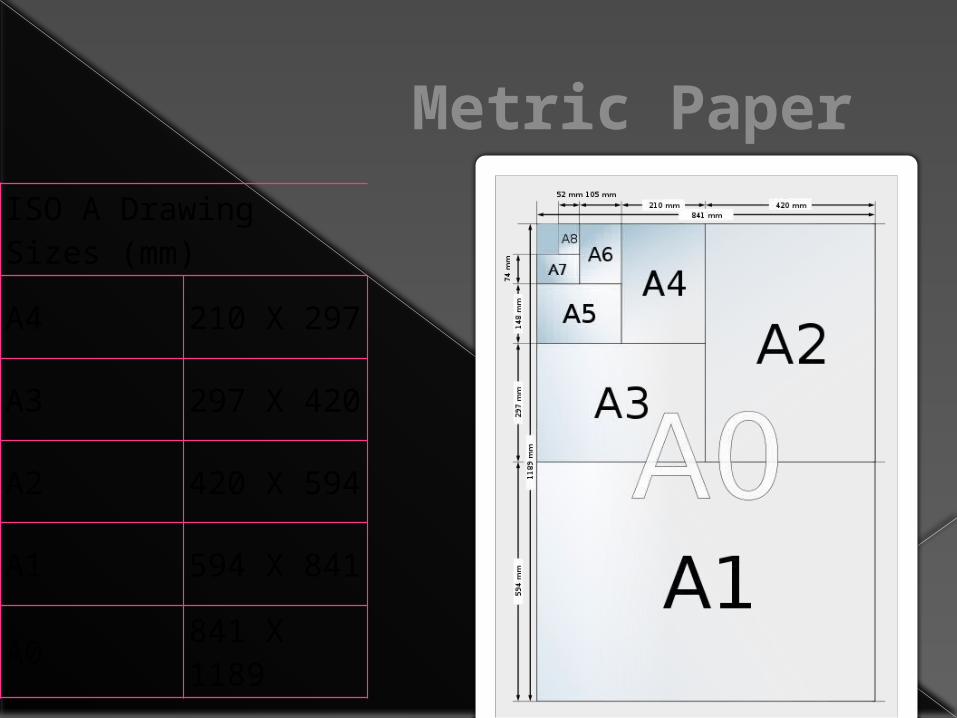
Metric PaperISO A Drawing Sizes (mm)
A4 210 X 297
A3 297 X 420
A2 420 X 594
A1 594 X 841
A0841 X 1189
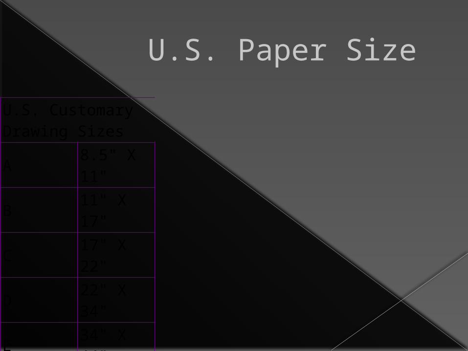
U.S. Paper Size
U.S. Customary Drawing Sizes
A8.5" X 11"
B11" X 17"
C17" X 22"
D22" X 34"
E34" X 44"

The Design Process Assignment (d2)
Designing new products, adapting or altering existing designs or creating something brand new is always a challenging task. However, if we can follow a process or a plan, we can often times shorten the time required to complete the project as well as ensure that we have not missed any necessary elements or crucial steps.
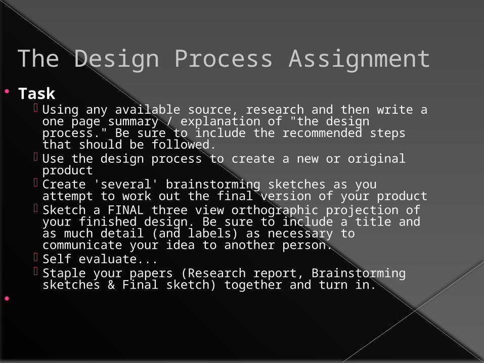
The Design Process Assignment Task
Using any available source, research and then write a one page summary / explanation of "the design process." Be sure to include the recommended steps that should be followed.
Use the design process to create a new or original product
Create 'several' brainstorming sketches as you attempt to work out the final version of your product
Sketch a FINAL three view orthographic projection of your finished design. Be sure to include a title and as much detail (and labels) as necessary to communicate your idea to another person.
Self evaluate... Staple your papers (Research report, Brainstorming
sketches & Final sketch) together and turn in.

CHAPTER 5 and REVIEW

Chapter 5
Vocabulary› Geometry› Geometric Construction› Vertex› Bisect› Perpendicular› Parallel› Polygon› Inscribe› Circumscribe› Regular Polygon› Ellipse

Geometry for Drafting
Chapter Objectives• Identify geometric shapes and constructions used by drafters.• Construct various geometric shapes. • Solve technical and mathematical problems through geometric
constructions using drafting instruments.• Solve technical and mathematical problems through geometric
constructions using a CAD system.• Use geometry to reduce or enlarge a drawing or to change its
proportions.

Geometry and Geometric Constuctions
What do you need to be able to understand geometric constructions?› Pythagorean Theorem (page 135 FG 5-2)› Page 136 FG 5-3

Applied Geometry for CAD Systems
Vocabulary› Object Snap› Ogee Curve› Intervals› Specify

Chapter 5.2
What do object snaps allow a drafter to do?› Midpoint› Nearest› Endpoint› Center› Intersection› Quadrant› Perpendicular› Tangent
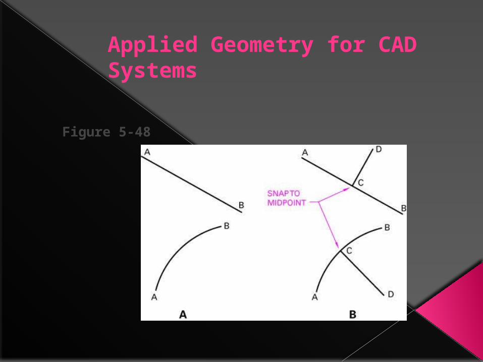
Applied Geometry for CAD Systems
Figure 5-48
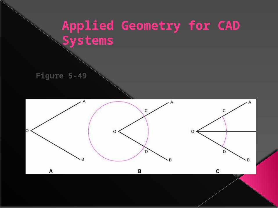
Applied Geometry for CAD Systems
Figure 5-49
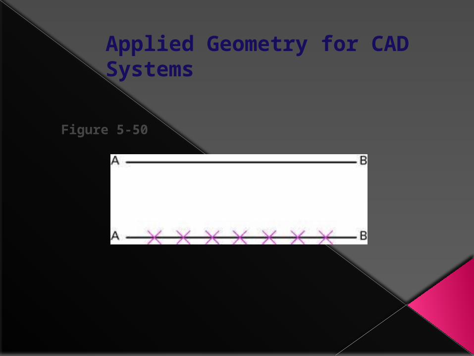
Applied Geometry for CAD Systems
Figure 5-50

Applied Geometry for CAD Systems
Figure 5-51

Applied Geometry for CAD Systems
Figure 5-52
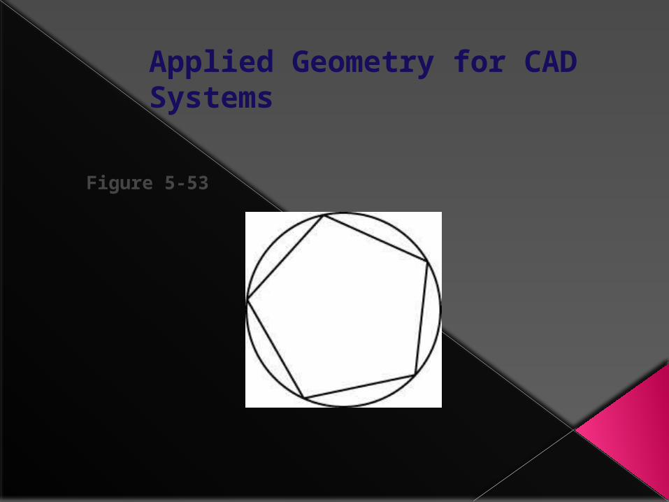
Applied Geometry for CAD Systems
Figure 5-53

Applied Geometry for CAD Systems
Figure 5-54
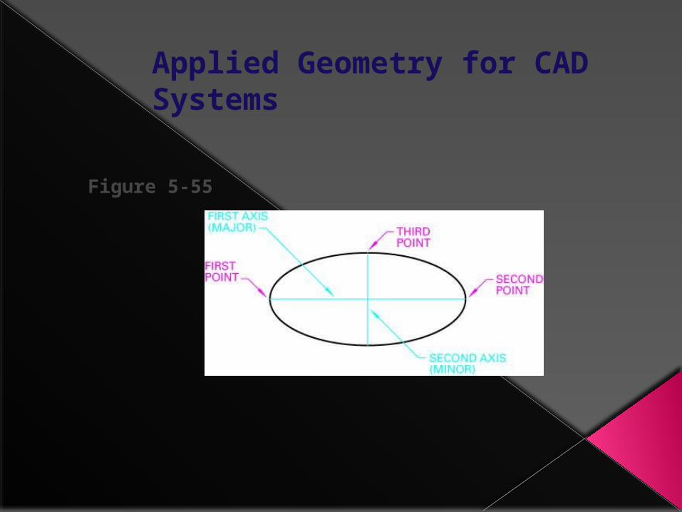
Applied Geometry for CAD Systems
Figure 5-55

Applied Geometry for CAD Systems
Figure 5-56

Applied Geometry for CAD Systems
Figure 5-57

Applied Geometry for CAD Systems
Figure 5-58

Applied Geometry for CAD Systems
Figure 5-59

Applied Geometry for CAD Systems
Figure 5-60
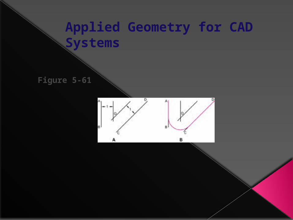
Applied Geometry for CAD Systems
Figure 5-61

Applied Geometry for CAD Systems
Figure 5-62

Applied Geometry for CAD Systems
Figure 5-63

Applied Geometry for CAD Systems
Figure 5-64
What's your assignment(s)
Drafting 2-4› You are to log on and open a word
document and type/define as many commands as you can remember.
› After describe how each can be done in AutoCAD in more than one way.
› You have till Friday to complete.› You will also be completing a small
challenge packet.

Drafting 4 will also
You will complete the Pre- Test for Architecture Chapter 1- Due Friday 9/2
And you will also complete› Pages 17–36› Review Questions, Suggested Activities› Due Next Thursday 9/8