“sky rockets in flight” experimental engineering section 1,team 3 student 1, student 2, student...
TRANSCRIPT

“Sky Rockets in Flight”
Experimental Engineering
Section 1,Team 3
Student 1, Student 2, Student 3, Student 4
May 5, 2008


Objectives
• Develop problem solving and critical thinking skills
• Utilize various disciplines of engineering
• Analyze and predict the flight of a rocket.

Prior to Launch
• Sensors Need to be Calibrated– Accelerometers, Gyroscopes, Pitot Tube, Pressure Sensor
• Physical Characteristics– Coefficients of Lift and Drag– Natural frequencies of rocket body
• Motor Quantities– Thrust Curve and Total Impulse for Modeling

Flight Modeling
• Calculate instantaneous acceleration:– Thrust Curve– Gravity– Lift (from wind)– Drag– Weather Cocking
• Euler’s Method to find trajectory
• Algorithm checked using RockSim

Algorithm
mass
VcAg
mass
Fa dthrusty *2
)cos(****)cos(
2 θρθ −−=
€
α =ρ *cL *W 2 * d
2Ix
Fthrust=Instantaneous thrust from motor
θ=angle from vertical
g = acceleration from gravity
A = cross sectional area
ρ=air density
Ix=Moment of Inertia about x axis
cD=drag coefficient
cL=lift coefficient
V=velocity
α=angular acceleration
W=wind speed
d= distance between CM and CP

0 2 4 6 8 10 12-200
0
200
400
y acceleration(m/s
2)
Rocket y Acceleration
0 2 4 6 8 10 12-1
0
1
2
x acceleration(m/s
2)
Rocket x Acceleration
0 2 4 6 8 10 12-100
0
100
y velocity(m/s)
Rocket y Velocity
0 2 4 6 8 10 12-100
0
100
200
y Displacement(m)
Rocket Altitude
0 2 4 6 8 10 12-4
-2
0
2
x velocity(m/s)
Rocket x Velocity
0 2 4 6 8 10 12-20
-10
0
10
time(sec)x Displacement(m)
Rocket x Displacement
0 2 4 6 8 10 120
2
4
time(sec)
radians
Rocket Tilt

Launches
• Lucerne Valley, CA --- dry lake bed
• 4/19 - Large IMU & Small IMU– Windy (15-25 mph)
• 4/26 - Large IMU & Large Vibration– No wind

IMU Sensors• Getting global coordinates from local coordinates
• Calibration for IMU
381.838)62784674.1(
483.109)21392.0(
596.91)17855.0(
+−=
+−=−=
azz
ayy
axx
va
vava
€
ωx = (1.43681)vwx − 730.179
ωy = (0.683)vwy − 417.313
ωx = (1.92815)vwz − 640.3745
∫ ∫∫∫∫∫ ∫∫∫∫∫ ∫∫∫∫
++=
+−=
+−=
yxxyzz
xzzxyy
zyyzxx
awawaV
awawaV
awawaV

4/19/08 IMU Height
Graph:Apogee @ 5.20 sec& 166 m
Predicted (RockSim):Apogee @ 6.17 sec& 183 m
Predicted (MATLAB):Apogee @ 5.94 sec& 171 m

4/26/08 IMU Height
Graph:Apogee @ 4.98 sec &181 m
Predicted (RockSim):Apogee @ 6.17 sec& 183 m
Predicted (MATLAB):Apogee @ 5.97 sec& 172 m

Integration Errors
Acceleration
•Euler’s Method•Dead Reckoning Error

Pressure Altimeter
• Pressure decreases with altitude
• (1)
• No Dead Reckoning Error
• Poor Sensitivity
⎟⎟⎠
⎞⎜⎜⎝
⎛⎟⎠
⎞⎜⎝
⎛−××=1902.
5
325.1011104544.1
kPa
Ph


Vibration Analysis
• Periods with limited external influence• Analyze short segments with FFT
0 0.05 0.1 0.15 0.2 0.25-150
-100
-50
0
50
100
150
200Sensor 1, 7, 12 Detrend Sampled Data
Time (sec)
Str
ain
Vol
tage
Out
put
Sensor 1Sensor 7sensor 12

Frequency Analysis
• Sampling frequency too low (200 Hz).• Fundamental frequency folded.
-100 -50 0 50 1000
5
10
15
Magnitude
Magnitude and Phase of FFT for Sensor 1
-100 -50 0 50 100-15
-10
-5
0
5
Frequency (Hz)
Phase (radians)
Sensor Frequency (Hz)
1 141.5
6 135, 137
7 140
10 135.5
12 141.5

Failed Flight…• Small IMU parachute did not deploy,
rocket went into a fatal flat spin.
• Pitot, Pressure: No activity.
• Accelerometers: Activity stops at t=0.

…Failed Flight
• Gyroscopes: unexpected activity before and after launch

Conclusions
• IMU: Accurate measurement, but limited by the low sampling frequency
• Vibration: Shows the expected reaction– vibration occurred at same frequency as
dynamic beam experiment

Recommendations
• GPS
• Higher sampling frequency in IMU and RDAS
• Looking at all 15 strain gauges at once
• Use the same IMU all semester

Acknowledgements
Student ProctorsRocket Development Team
Professor SpjutProfessor Miraghie
The Rest of the Engineering FacultySystem Admin
Stockroom Curator

References• 1. Anonymous "Model Rocket Safety Code," http://www.nar.org/NARmrsc.html.
• 2. Qimin Yang, “Pressure sensors and thermistors,” http://www.eng.hmc.edu/NewE80/PresTempLec.html.
• 3. Student 5, E80 Section 4, Team 2
• 4. Phillip D. Cha and John I. Molinder, Sampling and Data Acquisition, in Fundamentals of Signals and Systems: A Building Block Approach, edited by Anonymous (Cambridge University Press, New York, 2006), pp. 86-88.
• Anonymous, “Accelerometer and Gyroscope Calibration,” http://www.eng.hmc.edu/NewE80/AccelGyroLab.html.
• Anonymous, “Integrated Dual-Axis Gyro,” http://www.eng.hmc.edu/NewE80/PDFs/IDG_300_Datasheet.pdf
• Anonymous, “Analog Devices,”
• http://www.eng.hmc.edu/NewE80/PDFs/ADXL320.pdf
• Colin Holland, “Tri-axi inertial measurement unit combines seven sensors,” http://www.eetimes.eu/industrial/199905290
• Mary Cardenas, “Rocket Dynamics,” http://www.eng.hmc.edu/NewE80/PDFs/rocket_dynamics.pdf.

Questions?

Calibration equations
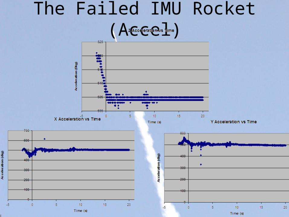
The Failed IMU Rocket (Accel)

The Failed IMU Rocket (Gyros)

Aliasing
• Sampling Theorem:
Sensor Dominant Frequency (Hz)
1 58.5
6 65, 67
7 60
10 64.5
12 58.5
saliasedsaliased ffnfff ≤⇒+=
Sensor Frequency (Hz)
1 141.5
6 135, 137
7 140
10 135.5
12 141.5

Detrend Data
0 0.5 1 1.5-10
-8
-6
-4
-2
0
2
4
6
8Sensor 10 Detrend Sampled Data
Time (sec)
Strain Output Voltage
Sensor 10
0 0.5 1 1.5-20
-15
-10
-5
0
5
10
15
20
25Sensor 10 Sampled data
Time (sec)
Strain Output Voltage
Sensor 10

FFT
-50 0 50 100
0
0.05
0.1
Magnitude and Phase of FFT for Sensor 10
Magnitude
-100 -50 0 50 100-100
-50
0
50
Frequency (Hz)
Phase (radians)