slab drainage tool - nemetschek groupdownload2cf.nemetschek.net/bim/slab-drainage-tool...3...
TRANSCRIPT

IN VECTORWORKS ARCHITECT
SLAB DRAINAGE TOOL A TUTORIAL

2 www.vectorworks.net
Written for Vectorworks Architect 2017

3
VECTORWORKS ARCHITECT Slab Drainage Tool
The Slab Drainage tool has the ability to create slabs with sloping components as well as the ability to place drains either internally or along the perimeter. This tool lends itself to the creation of “flat” roofs with the three most common usages listed below:
• Roof with internal drain(s) • Roof draining to scupper(s) or
gutter(s) • Sloping roof structure
This will be the focus of this document but it is conceivable that you could use the tool for creating sloped slabs in garages (both structured parking decks and residences) as well as sloped slabs for site work. A companion Vectorworks file “Slab Drainage Demo.vwx” can be used in conjunction with this tutorial. Enjoy!
INTRODUCTION

4 www.vectorworks.net
HOW DOES IT WORK? The tool works in conjunction with a Slab Style and can either create a roof with tapered components that slopes to drains OR it can create a slab/roof system that is sloped.
• Create a Slab Style with the appropriate components
• Draw a slab using the standard tools for slabs
• Apply the slab style • Set drains where required • Modify/edit as needed
For example, let’s assume we want to create a flat roof with tapered insulation with internal drains.
Create A Slab Style You’ve probably created slab styles in previous versions of the software and there is very little difference here when creating a style. The “magic” is two-fold and is found in the Edit Slab Style dialog in the Drainage pane. Here we must choose either Fixed Thickness Slab or Tapered Component. And second, we must choose which component (if any) will taper.
In the Drainage pane, we’ll choose Tapered Component – this informs the software that we want to taper a component. Then we’ll tell the software which component we want to taper – we’ll choose the Tapered Insulation. Looking at
Figure 1, we have:
Slab Style called “Tapered Components” with three components:
• A structural component (like concrete or metal pan/concrete)
• A tapering component (like tapered insulation)
• A topping component (like membrane roofing)
Note, in the column called Tapered, there’s a check mark next to the component called “Tapered Insulation.” Additionally, the tapering component’s Thickness is set to express the smallest dimension that we want the component to taper to, in this case 1”. So the tool will taper the insulation from 1” out to the edges and will tell us what those dimensions will be…automatically, based on where drains are set. Draw A Slab The next step is to create the slab and apply the appropriate slab style using our familiar tools resulting in a flat slab with flat components. Perfect. Set Drains To set drains, you can either right-click on the slab and use the contextual menu to select “Edit Drainage” or you can go to the Building Shell ToolSet and select the Slab Drainage Tool.
Fig. 1

5
VECTORWORKS ARCHITECT Slab Drainage Tool
The Slab Drainage Tool has four modes and a preferences option. (Fig. 2)
• Edit Mode • Create Drain Mode • Connect Drains Mode • Create Valley Mode • Preferences
We recommend setting the preferences first. (Fig.3) Slopes are entered as a percentage. The default settings are a good starting point. The type of drain “head” is selected first by checking the box Default Drain Symbol and then choosing from the drop-down. Creating classes for the various elements will let you maintain graphic control in your drawings. We’ll see the behavior once a drain is set.
Fig. 2
Fig. 3
6 www.vectorworks.net
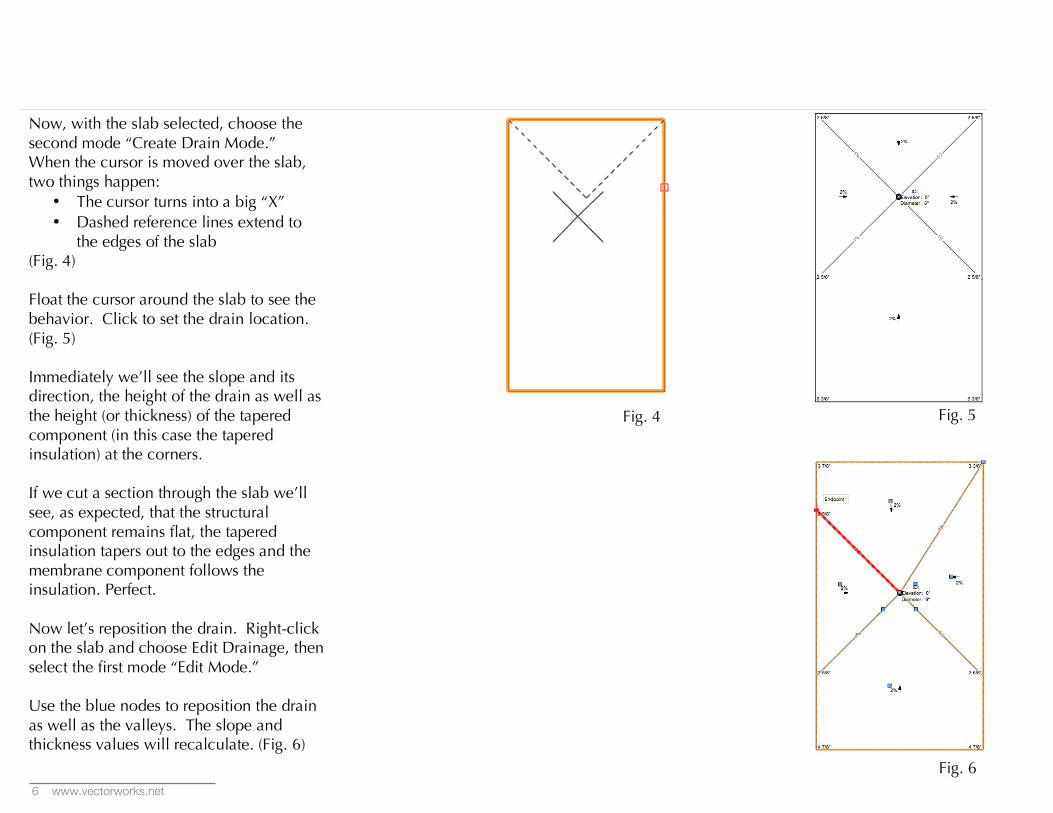
Now, with the slab selected, choose the second mode “Create Drain Mode.” When the cursor is moved over the slab, two things happen:
• The cursor turns into a big “X” • Dashed reference lines extend to
the edges of the slab (Fig. 4) Float the cursor around the slab to see the behavior. Click to set the drain location. (Fig. 5) Immediately we’ll see the slope and its direction, the height of the drain as well as the height (or thickness) of the tapered component (in this case the tapered insulation) at the corners. If we cut a section through the slab we’ll see, as expected, that the structural component remains flat, the tapered insulation tapers out to the edges and the membrane component follows the insulation. Perfect. Now let’s reposition the drain. Right-click on the slab and choose Edit Drainage, then select the first mode “Edit Mode.” Use the blue nodes to reposition the drain as well as the valleys. The slope and thickness values will recalculate. (Fig. 6)
Fig. 4
Fig. 5
Fig. 6

7
VECTORWORKS ARCHITECT Slab Drainage Tool
For larger roofs, more drains may be required. We can set additional drains and use the “Connect Drains Mode” to create a valley between two drains and then modify the valley by clicking on it to create a saddle. (Fig. 7A, B, C) Saddles can then be further modified to create the roof system you need. (Fig. 8)
Fig. 7A
Fig. 7B
Fig. 7C
Fig. 8
8 www.vectorworks.net
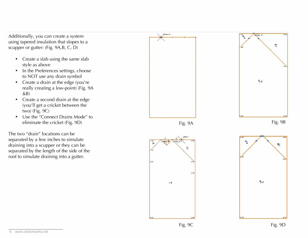
Additionally, you can create a system using tapered insulation that slopes to a scupper or gutter: (Fig. 9A,B, C, D)
• Create a slab using the same slab style as above
• In the Preferences settings, choose to NOT use any drain symbol
• Create a drain at the edge (you’re really creating a low-point) (Fig. 9A &B)
• Create a second drain at the edge (you’ll get a cricket between the two) (Fig. 9C)
• Use the “Connect Drains Mode” to eliminate the cricket (Fig. 9D)
The two “drain” locations can be separated by a few inches to simulate draining into a scupper or they can be separated by the length of the side of the roof to simulate draining into a gutter.
Fig. 9A
Fig. 9B
Fig. 9D
Fig. 9C

9
VECTORWORKS ARCHITECT Slab Drainage Tool
Create a Fixed Thickness Slab or Sloped Structure The Slab Drainage Tool can be used to create sloping slabs. Some buildings have bar joists that are set with a slope with the roof slab and components above following the slope. Other structures, like a parking deck in a parking garage, have a single concrete slab set on a slope. Creating a sloping slab is similar to the steps above although a bit more straightforward. (Fig. 10) In the Drainage pane, choose Fixed Thickness Slab. This informs the software that ALL components will slope once a “drain” is placed. Similar to the discussion above regarding sloping to a scupper, you really will place a “low spot” and not a drain at all.
In the Preferences settings, enter the percentage of slope that is needed.
Placing the drains is also similar to the scupper scenario, drains are placed along the edge and then “linked” or connected with the “Connect Drain Mode” Additional Editing Features
Editing a roof or slab that uses the Slab Drainage tool must be done in Top/Plan
Fig. 10
view and can be accomplished by right-clicking on the slab and choosing “Edit Drainage” from the contextual menu. Then choose the “Edit Mode” in the mode bar.
Edit Drains
Mouse over a drain until it glows red then right-click on a drain. You can change the symbol and the elevation as required.
Edit Valleys (Fig.11) Mouse over a valley until it glows red then right-click to select the valley. You then have the option to change the slope by percentage or by elevation.
Edit Saddles/Connections (Fig. 12) If you’ve connected two (or more) drains together, you can mouse over the connection until it glows red then right-click to select the connection. This editing function gives you the ability to add a saddle and/or change the slope.
In summary, the Slab Drainage tool gives the designer the ability to create “flat” roofs as well as other sloping slab scenarios along with the required data to produce plan views. In conjunction with slab association enhancements, a multitude of contemporary roof designs are possible.
Fig. 11
Fig. 12