slac-m-573 (misc) hardware and software for … · i slac-m-573 march 1969 (misc) hardware and...
TRANSCRIPT
I
SLAC-m-573 March 1969 (MISC)
HARDWARE AND SOFTWARE FOR EFFECTIVE MAN-MACHINE INTERACTION IN THE LABORATORP
W. F. Miller
Stanford University, Stanford, California
I. INTRODUCTION
In the last few years we have transposed a certain amount of our instrumentation problems from one of hardware engineering to one of software engineering. The advan- tages of software instrumentation have been discussed in a number of conferences, but the realization of these benefits has been slower and more costly than anticipated. We commonly hear the complaint that we underestimate the software effort or that software failures have hampered the full utilization of a system. I should like to call attention to a number of research activities under way which are directed toward helping with the software problem. In particular, I refer to the work on META-SYSTEMS. Meta-systems are systems for describing and implementing other systems, for example, for describing and compiling compilers, operating systems, console languages, etc.
Meta-systems are in contrast to generalized and/or extensible systems. In the latter the idea is to be able to add new features at run time. Both meta-systems and extensible systems require higher level description languages that are sufficient to include the fea- tures to be added. The difference resides in the method of implementation. In one case you re-compile to get the new features; in the other case you make run time extensions that have to be interpreted by the parent system. An excellent survey and critical evalu- ation is contained in the paper by Feldman and Gries. 1
Another area of research that should make contribution to the design and implemen- tation of man-machine systems is the work on models of control. There is no good ref- erence that I can give you other than the bibliography of references for a course I give on Controlof Computing Systems. 2 In a number of papers at this conference we hear ref- erence to the need for systems analysis. The systems analysis and model building in the area of control go hand-in-hand.
I believe that the work on meta-systems and models of control will be important on the hypothesis that the next few years will see refinement of technique and increased sophistica- tion in applications, some of which will introduce changes of scale and some will require greater generalization. In all cases there will be a heavy dependence on software, so that software engineering will be a foremost concern. I believe that we can expect a greater trend toward random access secondary storage (disks, drums, etc. ) as opposed to sequen- tial secondary storage (tapes). This transition will be essential for those experimentswhich expect to interact with large volumes of data on-line. I include both cases where (1) an ex- perimenter interacts by means of a console with a large data base or (2) a control program must interact with a large data base to carry out its control function. I believe very much in the experimental approach to the development of the man-machine systems. We can de- sign, then redesign and re-compile systems as our experience dictates by use of a meta- compiler. The meta-compiler has the same advantage for the system designer and imple- menter as FORTRAN has for the applications programmer.
*Work supported by the U. S. Atomic Energy Commission (Presented at the Conference on Computer Systems in EXperimental Nuclear Physics, Skytop, Penn., March 3-6, 1969)

II. META-SYSTEMS
The goals of the meta-systems research are: (1) to find description languages that represent the processes being studied , (2) to find machine representations of these de- scriptions, and (3) to find useful implementations of the meta-system for the analysis of the system and/or the control of its construction (compilation).
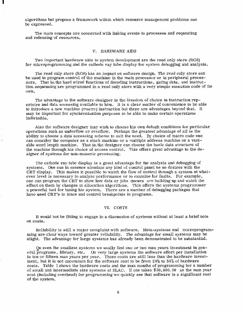
The order of increasing complexity of tasks for a meta-system is, in my experience, shown in Fig. 1.
I can point to highly successful utilization of meta-systems for area (I), moderately successful utilization in areas (2) and (3), and rather less use in areas (4) and (5). Use in areas (4) and (5) is increasing a% we gain better understanding of these processes. My own involvement is in (4) and (5) and it is in these areas that I shall illustrate the function- ing of a met-a-system.
I think it is clear why complexity increases from (1) to (5). As we go from (1) to (5) we become increasingly more involved in the dynamics of the computation. Also the data structures which form the low level representation of the processes become more complex from (1) to (5). In area (1) logical correctness is the main concern. Efficiency considera- tions are mainly related to code density. Areas (2) and (3) are concerned with storage allocation, either static or dynamic, whereas areas (4) and (5) are concerned with alloca- tion of many resources and with timing considerations, i. e. , scheduling. The need for experimentation in these latter areas is greater but the process description and modeling has been more elusive.
Intellectually, meta-systems contribute to better understanding of the programming processes. Practically they help one get systems “on the road” faster. The key idea is to use the meta-system to get a quick and dirty system “on the road” and then tune it in the areas where it needs improvement. A number of the manufacturer supplied compilers that you are using on your systems have been built that way. You get the quick version going and make certain that it is logically correct and then concern yourself about effi- ciency. The success of this technique in area (1) of Fig. 1 has been so enormous that I shall not dwell on it here.
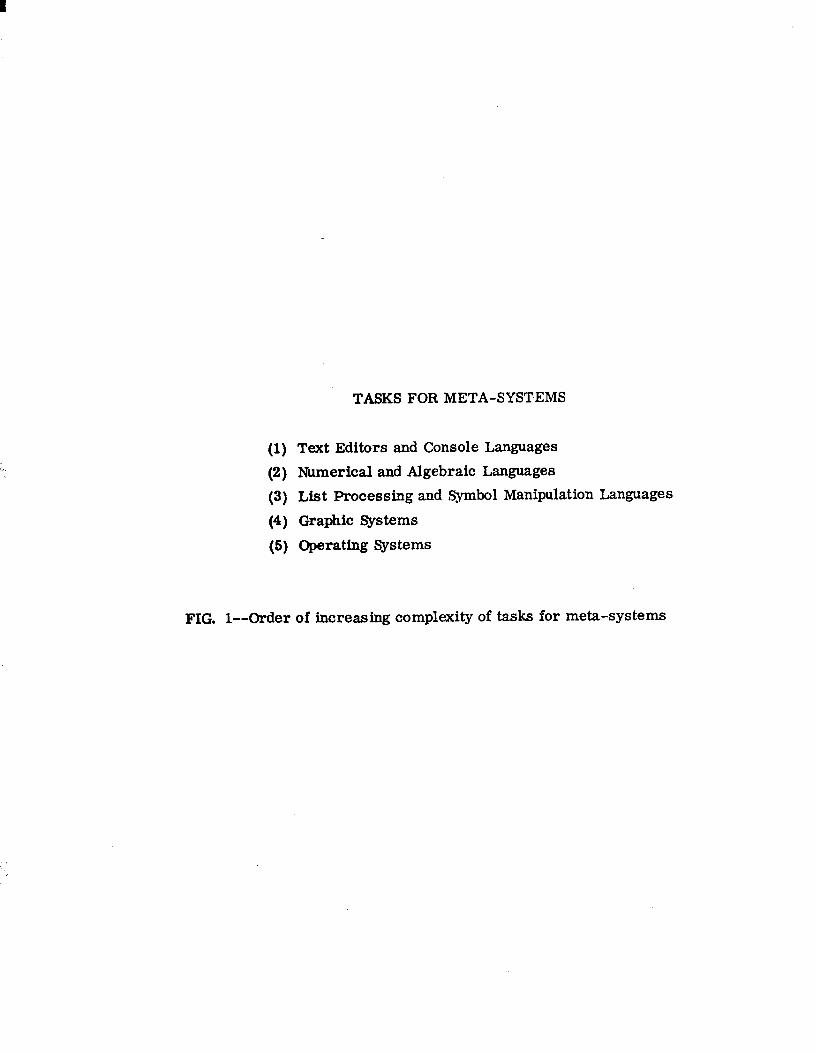
To date more effort has gone into meta-systems for compilers than for other areas. Some of the more successful ones known to me are listed in Fig, 2. For more complete comment readers are referred to the first paper in the bibliography. I
In addition to the special systems mentioned above, a number of compilers have been written in ordinary FORTRAN, ALGOL, or PL/I. Livermore has been writing their FORTRAN compilers using an extended version of FORTRAN for several years. The ACME PL time-sharing system at STANFORD was written in the IBMH-LEVEL FORTRAN, IBM is now putting a substantial effort into the development of PL/I as a system writing sys tern.
Let me point out that there is no particular magic in the meta-compiler operating on the machine for which it is compiling a system. The same statement is true for ordinary compilers and assemblers. There are a number of compilers (and assemblers) that com- pile on one machine for running on another. It is particularly convenient to compile and get a program to be syntactically correct using an interactive time-sharing machine before running on another machine. This may suggest to many a way out of the problem of having to buy a large amount of resource just to run a FORTRAN compiler.
Let us turn our attention to areas (3) and (4). The system problems here include the principal system problems for on-line data acquisition and control systems. The invest- ment of effort to make a meta-system for either graphics or operating systems becomes rather large and is not likely to be done by a small or even intermediate size applications group. I shall say more about the size of the effort later.
2

I ’
Figure 3 lists several meta-systems that have been used for compiling graphic con- trol and/or operating systems. All have been used in some form except item (4), GLAF, which is still under development. Perhaps the most successful in the sense of widest use of its products is the extended ALGOL of BURROUGHS. This was used to write the Master Control Program (MCP) for the disk-file monitor and succeeding monitors on the B-5500.
A much more ambitious project is the MIT PROJECT MAC Multics System. A spe- cialversionof PL/I was written (EPL) which was in turn used as the meta-compiler for the Multics operating system. The Multics system is designed for great generality, and it is currently struggling into operation and use. The effort has been much berated by some, but few people appreciate the enormity of the task. I believe they made the correct decision and seriously doubt if they could have been operational at all had they gone the path of machine language code.
III. GLAF, A GRAPHICS META-SYSTEM
My students and I are developing a Picture Calculus1o’11 that forms a model for picture processing, including both graphics and pattern recognition. In order to experi- ment with varying forms we need a meta-system for compiling systems based on our model.
Let me describe very quickly a particular instance of our general model of picture processing. Cur model is a linguistic or grammatical model. We have primitive ele- ments which are the basic entities from which pictures can be formed and a set of rules or operations for associating these primitives together. The rules for allowable asso- ciations are given in terms of a grammar.
The grammar can generate all allowable pit tures, that is all pictures that can be recognized or generated by this particular instance of our general model.
The picture description language. PDL permits one to describe the concatenation of the primitive elements of a picture. The choice of primitives will depend on the particular application. A primitive may be defined as any two-(n-) dimensional object with two dis- tinguished points, a tail and a head. In general, a primitive will be a pit ture that can be handled more conveniently as a unit than in terms of its subparts. Primitives are con- catenated together only at their heads and/or tails. Abstractly, a picture described in PDL can be represented as a labled, directed graph with the primitives as directed edges pointing from tail to head. We often refer to the graph of a picture.
Picture primitives are specified in terms of primitive classes which in turn are spec- ified by an attribute list. The attribute list contains the class name, a tail and head spec- ification, and an arbitrary list of additional attributes. As an example we may define the primitive class of arcs of circles of any radius, negative curvature, and arc less than 1800. The attribute of the primitive class ARC has the form
ARC = (ARC, Counterclockwise limit, Clockwise limit, Curvature < 0, $I < 18OO)
or
This is a specific instance of the general form
PRIMITIVE CLASS % (< NAME>, < tail specification>, <head specification>, ~1st attribute>, < 2nd attribute>, . . . <nth attribute>)
3

A superscript label identifies a particular member of a primitive class. An element ARC+ of the class ARC, for example, has a value list containing specific values for each attribute on the attribute list of the class, e. g. I
vALuE(ARC+) = (ARC+ , ?iTAIL, ZHEAD, (CURVATURE =) -2, (G =) 60’)
There may be redundant information on the attribute list. Some of the attributes may be irrelevant for some uses. However, for generality of form and application all infor- mation is retained.
We allow blank (invisible) and don’t care primitives. They may be used for connecting disjoint parts of a picture or to specify the geometrical relationship between parts of a picture. One special primitive, the null point primitive, A, plays a special role. It con- sists only of a tail and head with iden% position and it is represented as a labeled node in a graph.
The syntax of PDL is given as follows:
A sentence, S, in the language is defined by
1. 2.
~~~~~~““i”r”““F”‘wslsy _ *nl 3. p flJ a primitive class 4. I+, x, -8 * 1 are concatenation operators described below
-,r, T(o)) are unary operators I is a label designator
The concatenation operators +, X, - , * II and - are binary operators defined below. In all cases
i Tail ((S10S2)) = Tail (S1)
Head.((S1BS2)) = Head (S2), 8E (+, x, -, *,-I.
7. The + operator: head to tail : (Sl + S2) concatenates the head of SI to the tail of S2. Example :
h h
t- h /’ /’ t t-
Sl S2 ( s, +s, ) 8. The X operator: tail to tail:
(531 x S2) concatenates the tail of SI to the tail of S2. Example :
h
/’
h
t ---d a f
Sl s2 isI’s2j- 9. The - operator : head to head :
(Sl - S2) concatenates the head of S1 to the head of S2. Example : L t _ h
/I n
t
s2
4
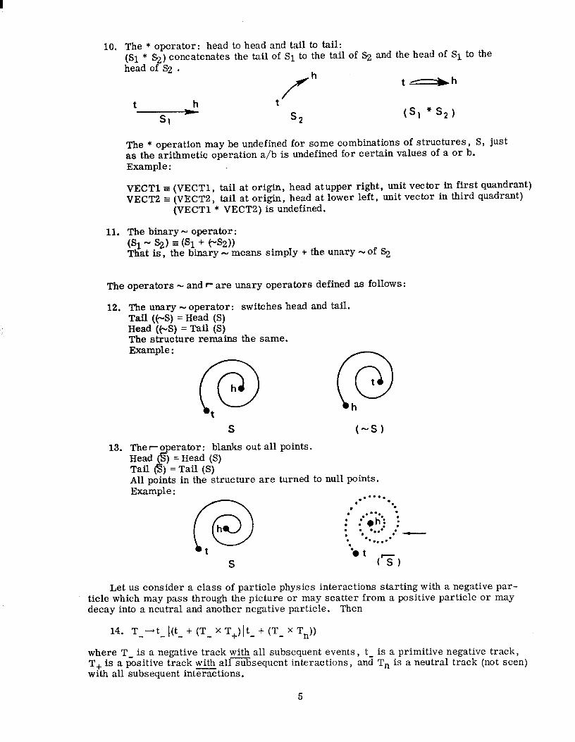
10.
11.
The * operator: head to head and tail to tail: (Sl * f+) concatenates the tail of S1 to the tail of S2 and the head of S1 to the head of S2 .
h t-h
t P Sl Pl * s, 1
The * operation may be undefined for some combinations of structures, S, just as the arithmetic operation a/b is undefined for certain values of a or b. Example :
VECTl = (VECTl, tail at origin, head atupper right, unit vector in first quandrant) VECTB = (VECTB , tail at origin, head at lower left, unit vector in third quadrant)
(VECTl * VECTZ) is undefined.
The binary - operator : @1- %) = ts1 + (“SZ)) That is, the binary - means simply + the unary -of S,
The operators - and r are unary operators defined as follows:
12. The unary - operator: switches head and tail. Tail ((a-S) = Head (S) Head (e-S) = Tail (S) The structure remains the same. Example :
@ @
S t-s)
13. The ro Head ( sp
erator: blanks out all points. ) = Head (S)
Tail 6) = Tail (S) All points in the structure are turned to null points. Example :
.* .a-*.
@
l . . .
l .
h : . .**;;;I ) . . . l
l ..* .’ a
. l *...-• . t ‘a t
S (Is)
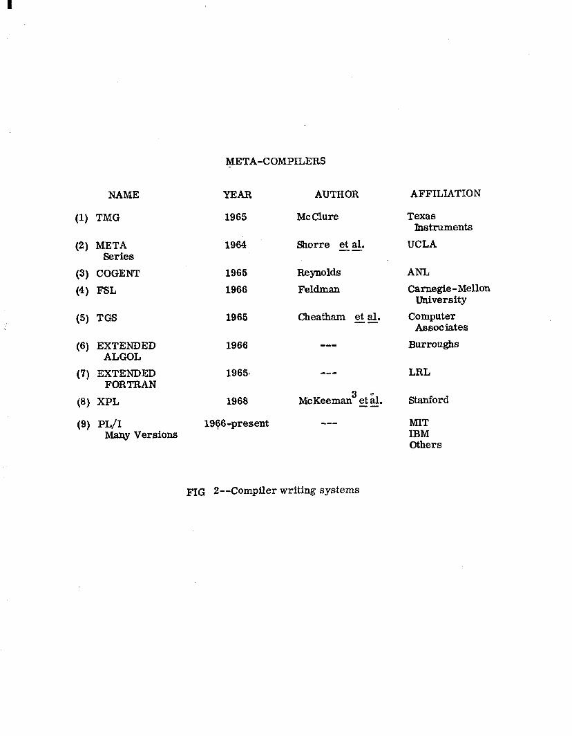
Let us consider a class of particle physics interactions starting with a negative par- ticle which may pass through the picture or may scatter from a positive particle or may decay into a neutral and another negative particle. Then
14. T--t- ttt, + tT_ x T+)(t- + (T- X T,))
where T- is a negative track with all subsequent events, t- is a primitive negative track, T, is a positive track with all subsequent interactions, and T, is a neutral track (not seen) with all subsequent interactions.
5
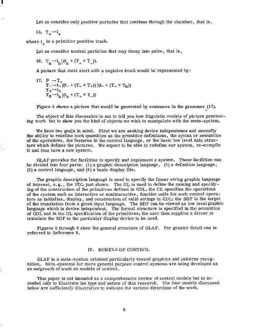
Let us consider only positive particles that continue through the chamber, that is,
15. T+-t+
where t, is a primitive positive track.
Let us consider neutral particles that may decay into pairs, that is,
16. Tn’tnlt tn + tT+ X T _ 1).
A picture that must start with a negative track would be represented by:
17. P -+T, 3’;‘:- I(t- + (T, X T-I-)) Itt- + (‘I’- X Tn))
+ Tn-tn I(& + (‘I’+ x T-J)
Figure 4 shows a picture that would be generated by sentences in the grammer (17). 4
The object of this discussion is not to tell you how linguistic models of pit ture process- ing work but to show you the kind of objects we wish to manipulate with the meta-system.
We have two goals in mind. First we are seeking device independence and secondly the ability to redefine such quantities as the primitive definitions, the syntax or semantics of the operations, the features in the control language, or the basic low level data struc- ture which defines the pictures. We expect to be able to redefine our system, re-compile it and thus have a new system.
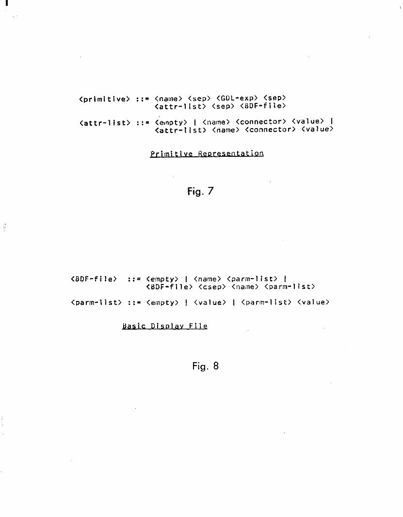
GLAF provides the facilities to specify and implement a system. These facilities can be divided into four parts : (1) a graphic description language, (2) a definition language, (3) a control language, and (4) a basic display file.
The graphic description language is used to specify the linear string graphic language of interest, e. g. , the PDL just shown. The DL is used to define the naming and specify- ing of the construction of the primitives defined in GDL; the CL specifies the operations of the system such as interactive or noninteractive, function calls for such control opera- tors as initialize, display, and construction of valid strings in GDL; the BDF is the target of the translation from a given input language. The BDF can be viewed as low level graphic language which is device independent. The formal structure is specified in the semantics of GDL and in the DL specification of the primitives; the user then supplies a driver to translate the BDF to the particular display device to be used.
Figures 5 through 8 show the general structure of GLAF. For greater detail one is referred to Reference 8.
IV. MODELS OF CONTROL
GLAF is a meta-system oriented particularly toward graphics and patterns recog- nition. Meta-systems for more general purpose control systems are being developed as an outgrowth of work on models of control.
This paper is not intended as a comprehensive review of control models but is in- tended only to illustrate the type and nature of this research. The four models discussed below are sufficiently illustrative to indicate the various directions of the work.
6
I
A. Dijkstra13
Dijkstra has been concerned with providing the primitive operations for control of shared processes. He has provided primitive operators with which one can guarantee the proper synchronization of two cooperating processes. Two particular dangers are (1) inadequate exclusion and (2) mutual exclusion. There are times when it is necessary to guarantee that all processes except one distinguished one are excluded from interacting with certain data or devices while the distinguished process is interacting (critical sec- tion). Dijkstra “semaphores” provide the mechanisms for providing this exclusion from critical set tions. The contrary danger, however, is that the synchronization mechansim will permit mutual exclusion. Mutual exclusion arises when each of two (or more) pro- cesses lays claim to a critical section only to find when it checks its claim that the other process has a claim thus excluding both processes. Such mutual exclusion is also pre- vented by the Dijkstra model of synchronization.
Dijkstra used his model as the basis of the design for ffTHEff-Multiprogramming System. l4 The model contributes to greater reliability and simplified debugging by prior knowledge of the logical soundness of the programs written.
B. Dennis and Van Horn 15
Dennis and Van Horn develop a set of primitive operations which not only provide for protection of critical sections but also permit the passage of control from one computation to another. This type of passage of control is essential to the development of a Wtility” system which expects to provide for common use of data and programs.
Many of the concepts advanced by Dennis and Van Horn have been utilized in the de- sign of MULTICS. 16
Both Dijkstra and Dennis and Van Horn have been concerned with the development of primitives and schemes for their use that provide for synchronization, various types of access control, and the passage of control from one process to another. Neither of these models provides global rules or a syntax for use of these primitives. A higher level language which incorporates these concepts might be developed and used for system writing.
C. Karp and Miller 17
Karp and Miller present a flow graph model of computation within which the sequencing of the processes of a computation is determined by the flow of data through the processes. Similar work is being done at MIT and at UCLA by a number of participants and at Stanford by the author and his students. A brief review of the work is contained in Reference 18.
In the flow graph models, the nodes of the graph represent processes (computation, data movement, etc. ) and the edges represent storage queues for transfer from one pro- cess to another. An example of a computation graph for the original Karp and Miller model17 is given in Fig. 9.
The careful definition of the conditions for initiation and termination of a process permit one to prove a priori that a program written in the model is determinate. By determinate we mean that no matter what the speed of the various processes nor what is the order of initiation of parallel processes, the sequence of outputs is always the same. This model has rather far reaching implications and a great deal of work is being directed toward exploiting the concepts.
D. Dahm, Cerbstadt, and Pacelli 19
These authors developed a set of primitive operations for management of resources in an event driven operating system. Similar ideas are contained in the work of BrownBo et al. , and Russell. 21 Dahm c a& , do not present scheduling and resource allocation --
7
I
algorithms but propose a framework within which resource management problems can be expressed.
The main concepts are concerned with linking events to processes and requesting and releasing of resources.
V. HARDWARE AIDS
Two important hardware aids to system development are the read only store (ROS) for microprogramming and the cathode ray tube display for system debugging and analysis.
The read only store (ROS) has an impact on software design. The read only store can he used to program control of the machine in the main processor or in peripheral proces- sors. That is, the hard wired functions of decoding instructions, gating data, and instruc- tion sequencing are programmed in a read only store with a very simple execution code of its own.
The advantage to the software designer is the freedom of choice in instruction rep- ertoire and data accessing available to him. It is a clear matter of convenience to be able to introduce a new machine (macro) instruction but there are advantages beyond that. It may be important for synchronization purposes to be able to make certain operations indivisible.
Also the software designer may wish to choose his own default conditions for particular operations such as underflow or overflow. Perhaps the greatest advantage of all is the ability to choose a data accessing scheme to suit the need. By choice of micro code one can consider the computer as a stack machine or a multiple address machine or a vari- able word length machine. That is, the designer can choose the basic data structure of the machine through his choice of access control. This offers great advantage to the de- signer of systems for non-numeric processing.
The cathode ray tube display is a great advantage for the analysis and debugging of systems. One can in essence simulate any kind of control panel he so desires with the CRT display. This makes it possible to watch the flow of control through a system at what- ever level is necessary to analyze performance or to examine for faults. For example, one can program the CRT to show how data or jobs queues are building up and watch the effect on them by changes in allocation algorithms. This offers the systems programmer a powerful tool for tuning his system. There are a number of debugging packages that have used CRT’s to trace and control breakpoints in programs.
VI. COSTS
It would not be fitting to engage in a discussion of systems without at least a brief note on costs.
Reliability is still a major complaint with software. Meta-systems and microprogram- ming are clear ways toward greater reliability. The advantage for small systems may be slight. The advantage for large systems has already been demonstrated to be substantial.
Qn even the smallest systems we usally find one or two man years investment in gen- eral programs, library, etc. On very large systems the software effort per installation is ten or fifteen man years per year. These costs are still less than the hardware invest- ment, but it is not uncommon for the software cost to be from 20% to 50% of hardware costs. Table I shows the hardware costs and the man months of programming for a number of small and intermediate size systems at SLAC. If one takes $30,000.00 as the man year cost (including overhead) for programming we quickly see that software is a significant cost of the system.
8

REFERENCES
1. J. Feldman and D. Gries, “Translator Writing Systems, ” C. A. C. M. 11, 77 (Feb. - 1968).
2. W. F. Miller, Bibliography of Papers for CS246, Control of Computing Systems, Computer Science Department, Stanford University, Stanford, California (1968).
3, W. M. McKeeman, J. J. Horning, and D. B. Wortman, XPL Users’ Manual, Stanford University Computation Center, Stanford University, Stanford, California (1968).
4. D. T. Ross et al. , -- AED-O Programmers Guide and User Kit, Electronic System Laboratory, MIT, Cambridge, Massachusetts; and D. T, Ross, “The AED Approach to Generalized Computer-Aided Design,” Proc. 22nd Nat?. Conf. of ACM, (1967) 367.
5. L. Mondschein, ‘Vital Compiler Reference Manual, ” TN-1967-1, Lincoln Lab. MIT, Lexington, Massachusetts (1967).
6. R. 9. Pankhurst, “GULP-A CompiIer-Compiler for Verbal and Graphic Languages,” Proc. ACM Nat’l. Conf. (1968) 405-421.
‘7. James E. George, “Calgen-An Interactive Pit ture Calculus Generation System, ” Report No. CS-114, Computer Science Department, Stanford University, Stanford, California (1968).
8. James E. George, “The System Specification of GLAF,” Report No. GSG61, Stanford Linear Accelerator Center, Stanford University, Stanford, California (1969).
9. Reference Manual on the Disk I/O Language of Extended ALGOL for the Burroughs B5500, Systems and Program Development, Burroughs Corporation, Pasadena, California (1964).
10. F. J. Corbatd and V. A. Vyssotsky, “Introduction and Overview of the Multics System,” Proc. FJCC, AFIPS 27, 185-196 (1965). -
11. W. F. Miller and A. C. Shaw, “A Picture Calculus,” Proc. Conf. on Emerging Concepts in Computer Graphics, (Benjamin Press, New York, N. Y. 1968)(SLAC-PUB-358).
12. W. F. Miller and A. C. Shaw, “Linguistic Methods in Picture Processing-A Survey, ” Fall Joint Computer Conference (1968) 279. (SLAC-PUB-429. )
13. E. W. Dijkstra, “CooperatingSequential Process, l’ Lecture Notes, Mathematics Department Technological University, Eindhaven, Holland, (Sept. 1965).
14. Edsger W. Dijkstra, “The Structure of the Multiprogramming System, ” C. A. C. M. 11, (May 1968) 341.
15. J. Dennis and E. Van Horn, “Programming Semantics for Multiprogrammed Com- putations , ” C. A. C. M. 9, (March 1966) 143.
16. R. C. Daley and J. B. Dennis, “Virtual Memory, Processes, and Sharing in MULTICS,” C. A. C. M. 11, (May 1968) 306. -
17. R. Karp and A. Miller, “Properties of a Model for Parallel Computations: Determin- acy, Termination, Queucing,” J. Appl. Math SIAM 14 1390 (Nov. 1966). -
9

I
18. Duane A. Adams, “A Computation Model with Data Flow Sequencing, It Report No. TN-CS-117, Computer Science Department, Stanford University, Stanford, California (Dec. 1968).
19. D. M. Dahm, F. H. Gerbstadt, and M. M. Pacelli, ItA System Organization for Resource Allocation, I1 C.A. C. M. 10, 772 (Dec. 1967).
20. R. M. Brown, M. A. Fisherkeller, A. E. Gromme, and J. V. Levy, “The SIAC High-Energy Spectrometer Data Acquisition and Analysis System, It Proc. IEEE 54, 1730 (Dec. 1966) (SLAC-PUB-205).
21. R. D. Russell, “MIDAS: A Multilevel Interactive Data Acquisition System,” IEEE 15th Nuclear Science Symposium, Montreal, Canada, (Oct. 23-25, 1968) (SLAC- PUB-511).
22. M. J. Flynn and M. D. MacLaren, “Microprogramming Revisited,” Proc. ACM Nat’l.. Meeting, (1967) 457.
10

Computer
Instsllation Date
First Use Date
SDS 925 SDS 9300
7/65
9/66
SDS 930 AS1 6020 PDP-8 PDP-9
11/67 10/66 2167 9167
mm- 3167 4/69 l/69 est.
IBM 1800 PDP-9
11/65
4/66
10/66
4/67
11/68
4/69 est.
Application Beam
Switch- wd
Spectrom- eter
Wire, Spark
Chamber
Hardware Cost* $lOOK $500K
Spectrom- Measuring Counter Spiral eter Machines Exp. Reader
$15OK $13OK $3OK $50K
Accelerator Control
$300K $90K
Software Effort (Man-Months)
General* *
Applicationst
Continuing Rate (permonth)
5 100 12 19 5 23 21 3 16 40 0 12 6 we 26 3
1 2 1 1 1 1 1 1.5
Dependence on Other Machines
9300 for assem:
blies none 9300
1401 for print/ punch
none 360for assem-
blies none none
* To nearest $lOK ** This includes testing and learning the supplier’s software, modifications and additions to the supplier’s software,
local developments on the control programs, general graphics packages, etc. -- these are programs that wiII be used by many or all the experiments.
TABLE I
SLAC SMALL COMPUTER INVESTMENTS
t This includes the analysis and data manipulation routines related to specific experiments.
TASKS FOR META-SYSTEMS
(1) Text Editors and Console Languages
(2) Numerical and Algebraic Languages
(3) List Processing and ,Symbol Manipulation Languages
(4) Graphic Systems
(5) Operating Systems
FIG. l--Order of increasing complexity of tasks for meta-systems
I
META-COMPILERS
NAME
(1) TMG
(2) META Series
(3) COGENT
(4) FSL
(5) TGs 1965
(6) EXTENDED ALGOL
(7) EXTENDED FORTRAN
(8) XPL
(9) WI Many Versions
YEAR
1965
1964
1965
1966
1966
1965.
1968
19fi6-present
AUTHOR AFFILIATION
MC Clure Texas hstruments
UCLA Shorre et al. --
Reynolds
Feldman
Cheatham et al. --
McKeeman3 et h --•
w-m
AN-L Carnegie-Mellon
University Computer
Associates
Burroughs
LRL
Stanford
MIT IBM Others
FIG 2--Compiler writing systems

(1) AED 1964 Ross4 Graphics
VITAL 1967 Mondschein’ Graphics
(2) GULP
(3) PWI (4) GLAF
(6) MIT PL/I
META’S FOR GRAPHICS AND CONTROL
1968
1968
Current
1966
Parkhurst’
George’
George’ 9 w-m
Graphics
Graphics
Graphics
B5500 Operating System
MIT
Lincoln Lab. MIT Cambridge Univ.
Stanford
Stanford Burroughs
1968 Project MAClO MuItics MIT
FIG. 3--Meta-systems for graphics and operating systems
I
P-(t-+((t-+(t+xt-)) x (t,+(t+x(t-+(t+xt-))I)))
IimT
FIG. 4-- PARTICLE PHYSICS PICTURE

Control Language a. Function Part b. Construction Part
Definition Language
Graphic Description Language a. Primitive Representation b. Syntax c. Semantics
Basic Display File
Fig. 5
<GLAF-language> ::= *GLAF* <data> ; <syntax> <semantic-list> <definition language> <control language> *END-i;LAF*
<semantic list> ::= <seanantics> 1 <semantic list> <semantics>
GLAF Syntax
Fig. 6
I
<primitive> ::= <name> <sep> <GDL-exp) <sep> <attr-list> <sep> <BDF-file>
<attr-1 ist> : := <empty> 1 <name> <connector> <value> I <attr-list> <name> <connector> <value>
. Primitive &m-esaLatlon.
Fig. 7
<EDF-file> ::= <empty> I <name> <parm-list> I <BDF-file> <csep> <name> <parm-list>
<parm-1 ist> ::= <empty> 1 <value> I <pat-m-l ist> <value>
isDlav File
Fig. 8
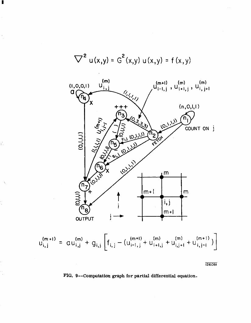
o2 u(x,y) = G2(x,y) uh,y) = f(x,Y)
OU%JT I i,j
m+l
(m+I) ui,j = ClUi,j (m)+gi,j
[ fi , j - ($,t: +
1 up j + q, + u’“,y’
1 I , )I 126061
FIG. O--Computation graph for partial differential equation.