slcet-tr-88-1 (rev. 8.5.2.2) ad-m001251 quartz crystal ... · “quartz crystal resonators and...
TRANSCRIPT
“QUARTZ CRYSTAL RESONATORS AND OSCILLATORSFor Frequency Control and Timing Applications - A TUTORIAL”Rev. 8.5.1.2, by John R. Vig, July 2001, AD-M001251.
John R. VigUS Army Communications-Electronics Research, Development & Engineering Center
Fort Monmouth, NJ, [email protected]
Approved for public release.Distribution is unlimited
Quartz Crystal Resonators and Oscillators
For Frequency Control and Timing Applications - A TutorialMarch 2004
SLCET-TR-88-1 (Rev. 8.5.2.2) AD-M001251
-

“QUARTZ CRYSTAL RESONATORS AND OSCILLATORSFor Frequency Control and Timing Applications - A TUTORIAL”Rev. 8.5.1.2, by John R. Vig, July 2001, AD-M001251.
NOTICES
The findings in this report are not to be construed as an official Department of the Army position, unless so designated by other authorized documents.
The citation of trade names and names of manufacturers in this report is not to be construed as official Government endorsement or consent or approval of commercial products or services referenced herein.
Disclaimer
-

“QUARTZ CRYSTAL RESONATORS AND OSCILLATORSFor Frequency Control and Timing Applications - A TUTORIAL”Rev. 8.5.1.2, by John R. Vig, July 2001, AD-M001251.
iii
Table of Contents
Preface………………………………..……………………….. v
1. Applications and Requirements………………………. 1
2. Quartz Crystal Oscillators………………………………. 2
3. Quartz Crystal Resonators……………………………… 3
4. Oscillator Stability………………………………………… 4
5. Quartz Material Properties……………………………... 5
6. Atomic Frequency Standards…………………………… 6
7. Oscillator Comparison and Specification…………….. 7
8. Time and Timekeeping…………………………………. 8
9. Related Devices and Applications……………………… 9
10. FCS Proceedings Ordering, Website, and Index………….. 10
-

“QUARTZ CRYSTAL RESONATORS AND OSCILLATORSFor Frequency Control and Timing Applications - A TUTORIAL”Rev. 8.5.1.2, by John R. Vig, July 2001, AD-M001251.
“Everything should be made as simple as possible - but not simpler,” said Einstein. The main goal of this “tutorial” is to assist with presenting the most frequently encountered concepts in frequency control and timing, as simply as possible.
I have often been called upon to brief visitors, management, and potential users of precision oscillators, and have also been invited to present seminars, tutorials, and review papers before university, IEEE, and other professional groups. In the beginning, I spent a great deal of time preparing these presentations. Much of the time was spent on preparing the slides. As I accumulated more and more slides, it became easier and easier to prepare successive presentations.
I was frequently asked for “hard-copies”of the slides, so I started organizing, addingsome text, and filling the gaps in the slide collection. As the collection grew, I began receiving favorable comments and requests for additional copies. Apparently, others, too, found this collection to be useful. Eventually, I assembled this document, the “Tutorial”.
This is a work in progress. I plan to include new material, including additional notes. Comments, corrections, and suggestions for future revisions will be welcome.
John R. Vig
iv
Preface
Why This Tutorial?
-
“QUARTZ CRYSTAL RESONATORS AND OSCILLATORSFor Frequency Control and Timing Applications - A TUTORIAL”Rev. 8.5.1.2, by John R. Vig, July 2001, AD-M001251.
v
In the PowerPoint version of this document, notes and referencescan be found in the “Notes” of most of the pages. To view the notes, use the “Notes Page View” icon (near the lower left corner of the screen), or select “Notes Page” in the View menu. In PowerPoint 2000 (and, presumably, later versions), the notes also appear in the “Normal view”.
To print a page so that it includes the notes, select Print in the File menu, and, near the bottom, at “Print what:,” select “Notes Pages”.
The HTML version can be viewed with a web browser (best viewed at 1024 x 768 screen size). The notes then appear in thelower pane on the right.
Many of the references are to IEEE publications that are available online in the IEEE UFFC-S digital archive, www.ieee-uffc.org/archiveor in IEEE Xplore, http://www.ieee.org/ieeexplore .
Notes and References
IEEE Xplore, <http://www.ieee.org/ieeexplore>, provides full-text access to IEEE transactions, journals, magazines and conference proceedings published since 1988 and to all current IEEE standards. Access to tables of contents of IEEE transactions, journals, magazines, conference is free to all. IEEE members can search and access all IEEE abstract/citation records and more...
“QUARTZ CRYSTAL RESONATORS AND OSCILLATORSFor Frequency Control and Timing Applications - A TUTORIAL”Rev. 8.5.1.2, by John R. Vig, July 2001, AD-M001251.
1
CHAPTER 1Applications and Requirements
Quartz for the National Defense Stockpile, Report of the Committee on Cultured Quartz for the National Defense Stockpile, National Materials Advisory Board Commission on Engineering and Technical Systems, National Research Council, NMAB-424, National Academy Press, Washington, D.C., 1985.
J. R. Vig, "Military Applications of High Accuracy Frequency Standards and Clocks," IEEE Transactions on Ultrasonics, Ferroelectrics, and Frequency Control, Vol. 40, pp. 522-527, 1993.
“QUARTZ CRYSTAL RESONATORS AND OSCILLATORSFor Frequency Control and Timing Applications - A TUTORIAL”Rev. 8.5.1.2, by John R. Vig, July 2001, AD-M001251.
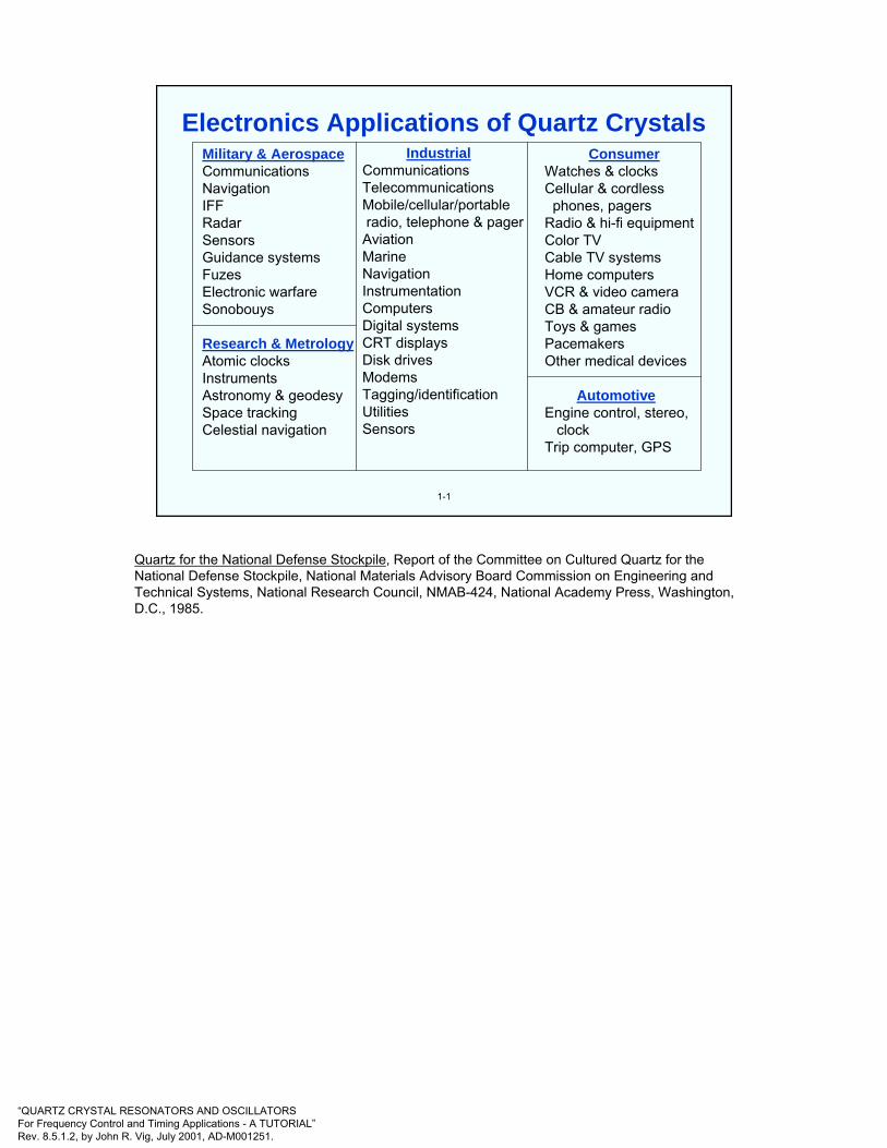
Military & AerospaceCommunicationsNavigationIFFRadarSensorsGuidance systemsFuzesElectronic warfareSonobouys
Research & MetrologyAtomic clocksInstrumentsAstronomy & geodesySpace trackingCelestial navigation
IndustrialCommunicationsTelecommunicationsMobile/cellular/portableradio, telephone & pager
AviationMarineNavigationInstrumentationComputersDigital systemsCRT displaysDisk drivesModemsTagging/identificationUtilitiesSensors
ConsumerWatches & clocksCellular & cordless
phones, pagersRadio & hi-fi equipmentColor TVCable TV systemsHome computersVCR & video cameraCB & amateur radioToys & gamesPacemakersOther medical devices
AutomotiveEngine control, stereo,
clockTrip computer, GPS
1-1
Electronics Applications of Quartz Crystals
Quartz for the National Defense Stockpile, Report of the Committee on Cultured Quartz for the National Defense Stockpile, National Materials Advisory Board Commission on Engineering and Technical Systems, National Research Council, NMAB-424, National Academy Press, Washington, D.C., 1985.
“QUARTZ CRYSTAL RESONATORS AND OSCILLATORSFor Frequency Control and Timing Applications - A TUTORIAL”Rev. 8.5.1.2, by John R. Vig, July 2001, AD-M001251.
1-2
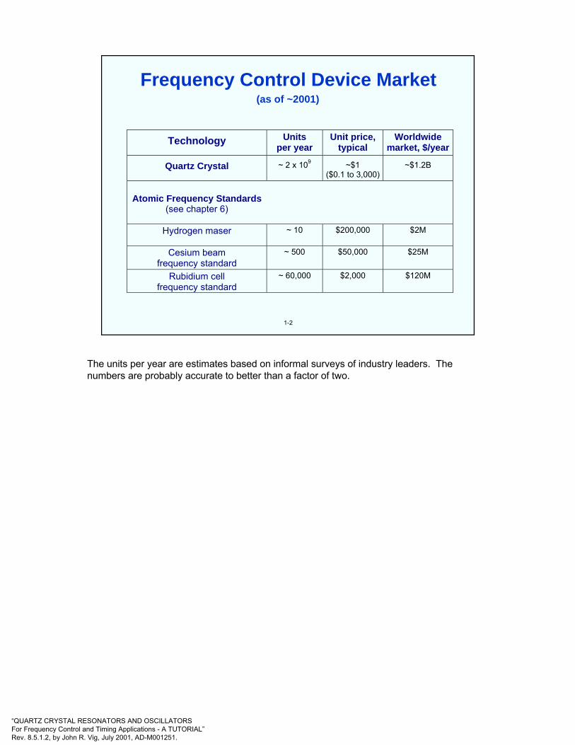
(as of ~2001)
Technology Units per year
Unit price, typical
Worldwide market, $/year
Quartz Crystal
~ 2 x 10⁹
~$1 ($0.1 to 3,000)
~$1.2B
Atomic Frequency Standards
(see chapter 6)
Hydrogen maser
~ 10 $200,000 $2M
Cesium beam frequency standard
~ 500 $50,000 $25M
Rubidium cell frequency standard
~ 60,000 $2,000 $120M
Frequency Control Device Market
The units per year are estimates based on informal surveys of industry leaders. The numbers are probably accurate to better than a factor of two.

“QUARTZ CRYSTAL RESONATORS AND OSCILLATORSFor Frequency Control and Timing Applications - A TUTORIAL”Rev. 8.5.1.2, by John R. Vig, July 2001, AD-M001251.
Precise time is essential to precise navigation. Historically, navigation has been a principal motivator in man's search for better clocks. Even in ancient times, one could measure latitude by observing the stars' positions. However, to determine longitude, the problem became one of timing. Since the earth makes one revolution in 24 hours, one can determine longitude form the time difference between local time (which was determined from the sun's position) and the time at the Greenwich meridian (which was determined by a clock):
Longitude in degrees = (360 degrees/24 hours) x t in hours.
In 1714, the British government offered a reward of 20,000 pounds to the first person to produce a clock that allowed the determination of a ship's longitude to 30 nautical miles at the end of a six week voyage (i.e., a clock accuracy of three seconds per day). The Englishman John Harrison won the competition in 1735 for his chronometer invention.
Today's electronic navigation systems still require ever greater accuracies. As electromagnetic waves travel 300 meters per microsecond, e.g., if a vessel's timing was in error by one millisecond, a navigational error of 300 kilometers would result. In the Global Positioning System (GPS), atomic clocks in the satellites and quartz oscillators in the receivers provide nanosecond-level accuracies. The resulting (worldwide) navigational accuracies are about ten meters (see chapter 8 for further details about GPS).
1-3
Navigation
Dava Sobel, Longitude, Walker & Co., New York, 1995

“QUARTZ CRYSTAL RESONATORS AND OSCILLATORSFor Frequency Control and Timing Applications - A TUTORIAL”Rev. 8.5.1.2, by John R. Vig, July 2001, AD-M001251.
1-4
Historically, as the number of users of commercial two-way radios have grown, channel spacings have been narrowed, and higher-frequency spectra have had to be allocated to accommodate the demand. Narrower channel spacings and higher operating frequencies necessitate tighter frequency tolerances for both the transmitters and the receivers. In 1940, when only a few thousand commercial broadcast transmitters were in use, a 500 ppm tolerance was adequate. Today, the oscillators in the many millions of cellular telephones (which operate at frequency bands above 800 MHz) must maintain a frequency tolerance of 2.5 ppm and better. The 896-901 MHz and 935-940 MHz mobile radio bands require frequency tolerances of 0.1 ppm at the base station and 1.5 ppm at the mobile station.
The need to accommodate more users will continue to require higher and higher frequency accuracies. For example, a NASA concept for a personal satellite communication system would use walkie-talkie-like hand-held terminals, a 30 GHz uplink, a 20 GHz downlink, and a 10 kHzchannel spacing. The terminals' frequency accuracy requirement is a few parts in 108.
Commercial Two-way Radio
R. Kinsman and D. Gunn, "Frequency Control Requirements for 800 MHz Land Mobile Communication," Proc. 35th Ann. Symp. Frequency Control, pp. 501-510, 1981.

“QUARTZ CRYSTAL RESONATORS AND OSCILLATORSFor Frequency Control and Timing Applications - A TUTORIAL”Rev. 8.5.1.2, by John R. Vig, July 2001, AD-M001251.
1-5
The Effect of Timing Jitter
A/Dconverter
A/Dconverter
DigitalprocessorDigital
processorD/A
converterD/A
converterAnalog*
inputAnalogoutput
Digitaloutput
Digitized signal
∆V
∆t
Time
Analog signal
(A)
(B) (C)
V(t)V(t)
* e.g., from an antenna
Digital Processing of Analog Signals
As microprocessor and digital signal processing (DSP) chips become more and more capable, the digital processing of analog signals, as illustrated in (A) above, becomes more and more advantageous and feasible. Among the advantages of digital (vs. analog) processing are that, in digital systems, many functions may be integrated on a chip (e.g., filtering, differentiation, integration, linearization, modulation, and computation), systems can be easily and inexpensively duplicated and reprogrammed, and systems do not depend on strict component tolerances.
Before an analog signal can processed, however, the signal must be converted into digital form. An analog-to-digital (A/D) converter (also abbreviated ADC) samples the analog signal at (usually) equal intervals of time, and converts the analog signal into a sequence of digitized values (i.e., the analog signal is sampled, measured, then converted into quantized numerical values), as illustrated in (B) above.
One of the sources of error in ADCs is jitter, i.e., the uncertainty in the time the signal was sampled. As shown in (C), an error ∆t in the time of the sampling causes an error ∆V in the measured value of the signal. The higher the resolution (number of bits) and the speed of the ADC, the smaller the allowable jitter. At GHz frequencies, some 16 bit ADC clock jitter requirements are a few femtoseconds.
Phase noise of the oscillator that drives the clock is one of the sources of timing jitter. The oscillator’s contribution to jitter is the integral of the phase noise, L(f), usually from 10 Hz to ~30 MHz.
J. A. Wepman, “Analog-to-Digital Converters and Their Applications in Radio Receivers,” IEEE Communications Magazine, pp. 39-45, May 1995.
R. J. Lackey and D. W Upmal, “Speakeasy: The Military Software Radio,” IEEE Communications Magazine, pp. 56-61, May 1995.

“QUARTZ CRYSTAL RESONATORS AND OSCILLATORSFor Frequency Control and Timing Applications - A TUTORIAL”Rev. 8.5.1.2, by John R. Vig, July 2001, AD-M001251.
• Synchronization plays a critical role in digital telecommunication systems. It ensures that information transfer is performed with minimal buffer overflow or underflow events, i.e., with an acceptable level of "slips." Slips cause problems, e.g., missing lines in FAX transmission, clicks in voice transmission, loss of encryption key in secure voice transmission, and data retransmission.
• In AT&T's network, for example, timing is distributed down a hierarchy of nodes. A timing source-receiver relationship is established between pairs of nodes containing clocks. The clocks are of four types, in four "stratum levels."
1-6
Stratum
1
2
3
4
Accuracy (Free Running)Long Term Per 1st Day
1 x 10-11 N.A.
1.6 x 10⁻⁸ 1 x 10⁻¹⁰
4.6 x 10⁻⁶ 3.7 x 10⁻⁷
3.2 x 10⁻⁵ N.A.
Clock Type
GPS W/Two Rb
Rb Or OCXO
OCXO Or TCXO
XO
Number Used
16
~200
1000’s
~1 million
Digital Network Synchronization
J. E. Abate, E. W. Butterline, R. A. Carley, P. Greendyk, A. M. Montenegro, C. D. Near, S. H. Richman, and G. P. Zampetti, AT&T's New Approach to the Synchronization of Telecommunication Networks," IEEE Communications Magazine, pp. 35-45, April 1989.
J. Pan, "Present and Future of Synchronization in the US Telephone Network," IEEE Transactions on Ultrasonics, Ferroelectrics, and Frequency Control, Vol. UFFC-34, No. 6, pp. 629-638, November 1987.
P. Kartaschoff, “Synchronization in Digital Communications networks,” Proc. IEEE, vol. 79, pp. 906-914, 1991.

“QUARTZ CRYSTAL RESONATORS AND OSCILLATORSFor Frequency Control and Timing Applications - A TUTORIAL”Rev. 8.5.1.2, by John R. Vig, July 2001, AD-M001251.
1-7
The phase noise of oscillators can lead to erroneous detection of phase transitions, i.e., to bit errors, when phase shift keyed (PSK) digital modulation is used. In digital communications, for example, where 8-phase PSK is used, the maximum phase tolerance is ±22.5o, of which ±7.5o is the typical allowable carrier noise contribution. Due to the statistical nature of phase deviations, if the RMS phase deviation is 1.5o, for example, the probability of exceeding the ±7.5o phase deviation is 6 X 10⁻⁷, which can result in a bit error rate that is significant in some applications.
Shock and vibration can produce large phase deviations even in "low noise" oscillators. Moreover, when the frequency of an oscillator is multiplied by N, the phase deviations are also multiplied by N. For example, a phase deviation of 10-3 radian at 10 MHz becomes 1 radian at 10 GHz. Such large phase excursions can be catastrophic to the performance of systems, e.g., of those which rely on phase locked loops (PLL) or phase shift keying (PSK). Low noise, acceleration insensitive oscillators are essential in such applications.
Phase Noise in PLL and PSK Systems
See the acceleration effects section in chapter 4 for further information about acceleration induced noise and phase excursions.
J. E. Abate, E. W. Butterline, R. A. Carley, P. Greendyk, A. M. Montenegro, C. D. Near, S. H. Richman, and G. P. Zampetti, AT&T's New Approach to the Synchronization of Telecommunication Networks," IEEE Communications Magazine, pp. 35-45, April 1989.
J. Pan, "Present and Future of Synchronization in the US Telephone Network," IEEE Transactions on Ultrasonics, Ferroelectrics, and Frequency Control, Vol. UFFC-34, No. 6, pp. 629-638, November 1987.
P. Kartaschoff, “Synchronization in Digital Communications networks,” Proc. IEEE, vol. 79, pp. 906-914, 1991.
“QUARTZ CRYSTAL RESONATORS AND OSCILLATORSFor Frequency Control and Timing Applications - A TUTORIAL”Rev. 8.5.1.2, by John R. Vig, July 2001, AD-M001251.
1-8
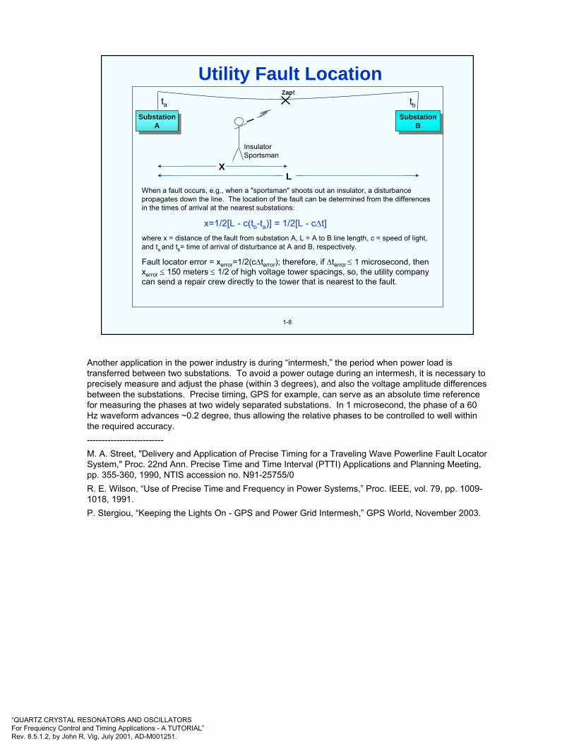
When a fault occurs, e.g., when a "sportsman" shoots out an insulator, a disturbance propagates down the line. The location of the fault can be determined from the differences in the times of arrival at the nearest substations:
x=1/2[L - c(tb-ta)] = 1/2[L - c∆t]where x = distance of the fault from substation A, L = A to B line length, c = speed of light, and ta and tb= time of arrival of disturbance at A and B, respectively.
Fault locator error = xerror=1/2(c∆terror); therefore, if ∆terror ≤ 1 microsecond, then xerror ≤ 150 meters ≤ 1/2 of high voltage tower spacings, so, the utility company can send a repair crew directly to the tower that is nearest to the fault.
SubstationA
SubstationA
SubstationB
SubstationB
Insulator Sportsman
XL
Zap!ta tb
Utility Fault Location
Another application in the power industry is during “intermesh,” the period when power load is transferred between two substations. To avoid a power outage during an intermesh, it is necessary to precisely measure and adjust the phase (within 3 degrees), and also the voltage amplitude differences between the substations. Precise timing, GPS for example, can serve as an absolute time reference for measuring the phases at two widely separated substations. In 1 microsecond, the phase of a 60 Hz waveform advances ~0.2 degree, thus allowing the relative phases to be controlled to well within the required accuracy.--------------------------M. A. Street, "Delivery and Application of Precise Timing for a Traveling Wave Powerline Fault Locator System," Proc. 22nd Ann. Precise Time and Time Interval (PTTI) Applications and Planning Meeting, pp. 355-360, 1990, NTIS accession no. N91-25755/0R. E. Wilson, “Use of Precise Time and Frequency in Power Systems,” Proc. IEEE, vol. 79, pp. 1009-1018, 1991.P. Stergiou, “Keeping the Lights On - GPS and Power Grid Intermesh,” GPS World, November 2003.
“QUARTZ CRYSTAL RESONATORS AND OSCILLATORSFor Frequency Control and Timing Applications - A TUTORIAL”Rev. 8.5.1.2, by John R. Vig, July 2001, AD-M001251.
1-9
θ(t)
∆θ
Wavefront
Meanwavelength λ
∆θ
∆t
Local Time &
FrequencyStandard
Local Time &
FrequencyStandard
Schematic of VBLITechnique
Microwavemixer
RecorderRecorder
MicrowavemixerLocal
Time &FrequencyStandard
Local Time &
FrequencyStandard
RecorderRecorder
Correlationand
Integration
Correlationand
Integration
Data tapeData tape
θ∆∆θ
Lsintc
=
Amplitude InterferenceFringes
θsinλ/L ( ) Angleτθ
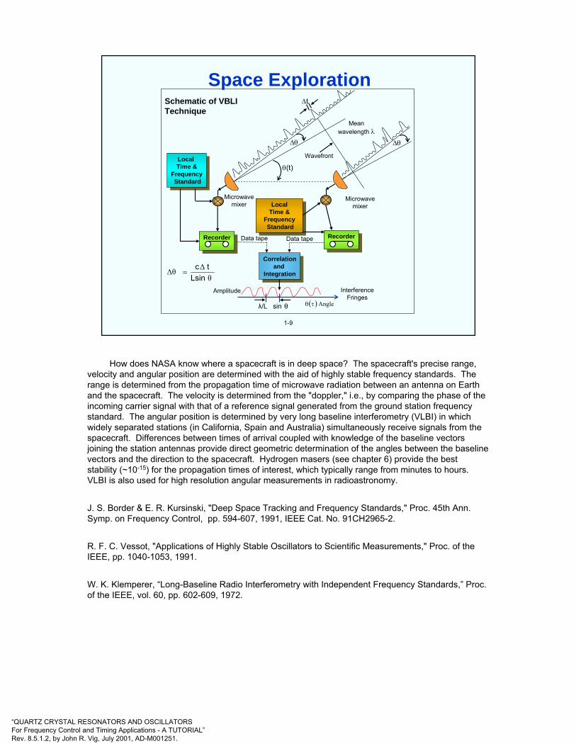
Space Exploration
How does NASA know where a spacecraft is in deep space? The spacecraft's precise range, velocity and angular position are determined with the aid of highly stable frequency standards. The range is determined from the propagation time of microwave radiation between an antenna on Earth and the spacecraft. The velocity is determined from the "doppler," i.e., by comparing the phase of the incoming carrier signal with that of a reference signal generated from the ground station frequency standard. The angular position is determined by very long baseline interferometry (VLBI) in which widely separated stations (in California, Spain and Australia) simultaneously receive signals from the spacecraft. Differences between times of arrival coupled with knowledge of the baseline vectors joining the station antennas provide direct geometric determination of the angles between the baseline vectors and the direction to the spacecraft. Hydrogen masers (see chapter 6) provide the best stability (~10-15) for the propagation times of interest, which typically range from minutes to hours. VLBI is also used for high resolution angular measurements in radioastronomy.
J. S. Border & E. R. Kursinski, "Deep Space Tracking and Frequency Standards," Proc. 45th Ann.Symp. on Frequency Control, pp. 594-607, 1991, IEEE Cat. No. 91CH2965-2.
R. F. C. Vessot, "Applications of Highly Stable Oscillators to Scientific Measurements," Proc. of the IEEE, pp. 1040-1053, 1991.
W. K. Klemperer, “Long-Baseline Radio Interferometry with Independent Frequency Standards,” Proc. of the IEEE, vol. 60, pp. 602-609, 1972.
“QUARTZ CRYSTAL RESONATORS AND OSCILLATORSFor Frequency Control and Timing Applications - A TUTORIAL”Rev. 8.5.1.2, by John R. Vig, July 2001, AD-M001251.
1-10
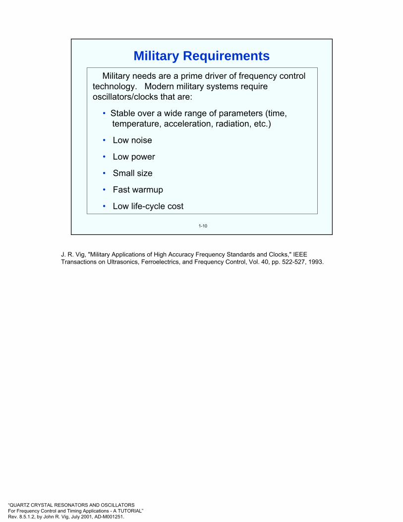
Military needs are a prime driver of frequency control technology. Modern military systems require oscillators/clocks that are:
• Stable over a wide range of parameters (time, temperature, acceleration, radiation, etc.)
• Low noise
• Low power
• Small size
• Fast warmup
• Low life-cycle cost
Military Requirements
J. R. Vig, "Military Applications of High Accuracy Frequency Standards and Clocks," IEEE Transactions on Ultrasonics, Ferroelectrics, and Frequency Control, Vol. 40, pp. 522-527, 1993.
“QUARTZ CRYSTAL RESONATORS AND OSCILLATORSFor Frequency Control and Timing Applications - A TUTORIAL”Rev. 8.5.1.2, by John R. Vig, July 2001, AD-M001251.
1-11
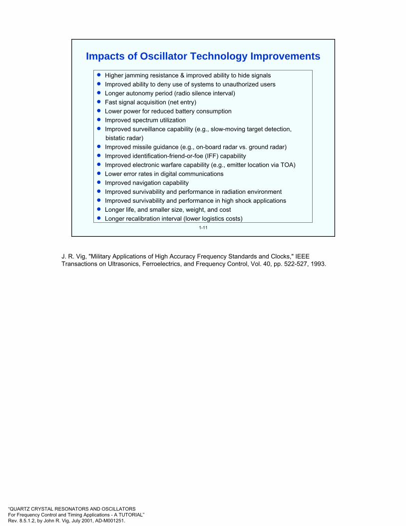
• Higher jamming resistance & improved ability to hide signals• Improved ability to deny use of systems to unauthorized users• Longer autonomy period (radio silence interval)• Fast signal acquisition (net entry)• Lower power for reduced battery consumption• Improved spectrum utilization• Improved surveillance capability (e.g., slow-moving target detection,
bistatic radar)• Improved missile guidance (e.g., on-board radar vs. ground radar)• Improved identification-friend-or-foe (IFF) capability• Improved electronic warfare capability (e.g., emitter location via TOA)• Lower error rates in digital communications• Improved navigation capability• Improved survivability and performance in radiation environment• Improved survivability and performance in high shock applications• Longer life, and smaller size, weight, and cost• Longer recalibration interval (lower logistics costs)
Impacts of Oscillator Technology Improvements
J. R. Vig, "Military Applications of High Accuracy Frequency Standards and Clocks," IEEE Transactions on Ultrasonics, Ferroelectrics, and Frequency Control, Vol. 40, pp. 522-527, 1993.
“QUARTZ CRYSTAL RESONATORS AND OSCILLATORSFor Frequency Control and Timing Applications - A TUTORIAL”Rev. 8.5.1.2, by John R. Vig, July 2001, AD-M001251.
1-12
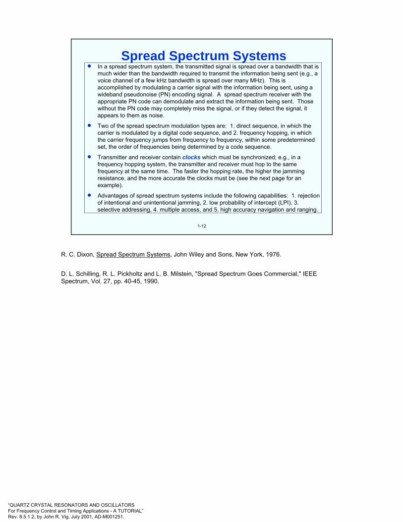
• In a spread spectrum system, the transmitted signal is spread over a bandwidth that is much wider than the bandwidth required to transmit the information being sent (e.g., a voice channel of a few kHz bandwidth is spread over many MHz). This is accomplished by modulating a carrier signal with the information being sent, using a wideband pseudonoise (PN) encoding signal. A spread spectrum receiver with the appropriate PN code can demodulate and extract the information being sent. Those without the PN code may completely miss the signal, or if they detect the signal, it appears to them as noise.
• Two of the spread spectrum modulation types are: 1. direct sequence, in which the carrier is modulated by a digital code sequence, and 2. frequency hopping, in which the carrier frequency jumps from frequency to frequency, within some predetermined set, the order of frequencies being determined by a code sequence.
• Transmitter and receiver contain clocks which must be synchronized; e.g., in a frequency hopping system, the transmitter and receiver must hop to the same frequency at the same time. The faster the hopping rate, the higher the jamming resistance, and the more accurate the clocks must be (see the next page for an example).
• Advantages of spread spectrum systems include the following capabilities: 1. rejection of intentional and unintentional jamming, 2. low probability of intercept (LPI), 3. selective addressing, 4. multiple access, and 5. high accuracy navigation and ranging.
Spread Spectrum Systems
R. C. Dixon, Spread Spectrum Systems, John Wiley and Sons, New York, 1976.
D. L. Schilling, R. L. Pickholtz and L. B. Milstein, "Spread Spectrum Goes Commercial," IEEE Spectrum, Vol. 27, pp. 40-45, 1990.

“QUARTZ CRYSTAL RESONATORS AND OSCILLATORSFor Frequency Control and Timing Applications - A TUTORIAL”Rev. 8.5.1.2, by John R. Vig, July 2001, AD-M001251.
1-13
Example
Let R1 to R2 = 1 km, R1 toJ =5 km, and J to R2 = 5 km. Then, since propagationdelay =3.3 µs/km, t1 = t2 = 16.5 µs, tR = 3.3 µs, and tm < 30 µs. Allowed clock error ≈ 0.2 tm
≈ 6 µs.
For a 4 hour resynch interval, clock accuracy requirement is:
4 X 10⁻¹⁰
To defeat a “perfect” followerjammer, one needs a hop-rate given by:
tm < (t1 + t2) - tRwhere tm ≈ message duration/hop
≈ 1/hop-rate
Jammer J
RadioR1
RadioR2
t1 t2
tR
Clock for Very Fast Frequency Hopping Radio
With the availability of fast spectrum analyzers and synthesizers, it is possible to jam frequency hopping systems. If a jammer is fast enough, it can detect the frequency of transmission and tune the jammer to that frequency well before the radio hops to the next frequency. However, with a good enough clock, it is possible to defeat such “follower” jamming. As illustrated above, even a "perfect" follower jammer can be defeated if a good enough clock is available. (A perfect jammer is defined here as one that can identify the frequency of a received signal, tune a synthesizer to that frequency, and transmit the jamming signal in zero time.)
Because radio waves travel at the speed of light, the radio-to-jammer-to-radio (R1 to J to R2) and radio-to-radio (R1 to R2) propagation delays are 3.3 µs per km. Therefore, if the hopping rate is fast enough for the propagation delay difference to be greater than 1/hop-rate, i.e., if the radios can hop to the next frequency before the jamming signal reaches the receiver, then the radios are jamming-proof (for follower jammers). In the example above, the propagation delays t1, t2, and tRimply that the message duration tm be less than 30 µs. Since the clock accuracies required by frequency hopping systems are usually 10% to 20% of tm, the allowed clock error is about 6 µs. In a military environment, such accuracies can be maintained for periods of hours and longer only with atomic clocks.
A. D. Robertson and F. C. Painter, "Tactical Jamming," Defense Science and Engineering, pp. 20-28, September 1985.
J. R. Vig, "Military Applications of High Accuracy Frequency Standards and Clocks," IEEE Transactions on Ultrasonics, Ferroelectrics, and Frequency Control, Vol. 40, pp. 522-527, 1993.
“QUARTZ CRYSTAL RESONATORS AND OSCILLATORSFor Frequency Control and Timing Applications - A TUTORIAL”Rev. 8.5.1.2, by John R. Vig, July 2001, AD-M001251.
1-14
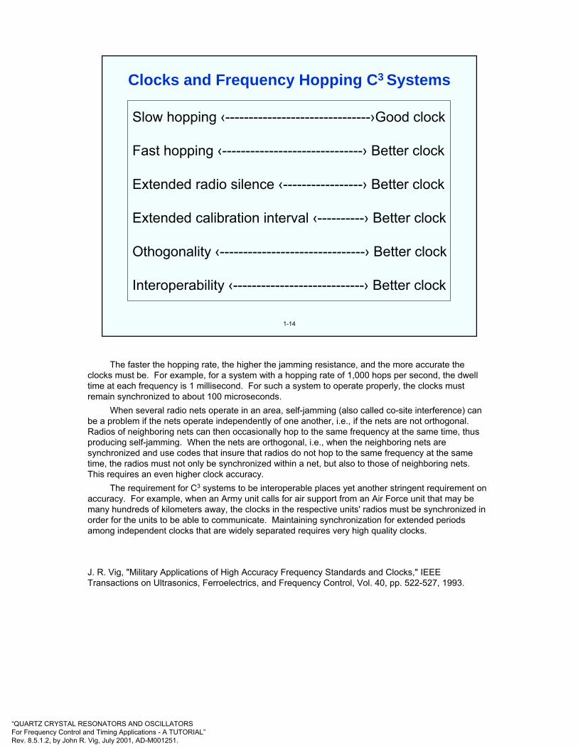
Slow hopping ‹-------------------------------›Good clock
Fast hopping ‹------------------------------› Better clock
Extended radio silence ‹-----------------› Better clock
Extended calibration interval ‹----------› Better clock
Othogonality ‹-------------------------------› Better clock
Interoperability ‹----------------------------› Better clock
Clocks and Frequency Hopping C3 Systems
The faster the hopping rate, the higher the jamming resistance, and the more accurate the clocks must be. For example, for a system with a hopping rate of 1,000 hops per second, the dwell time at each frequency is 1 millisecond. For such a system to operate properly, the clocks must remain synchronized to about 100 microseconds.
When several radio nets operate in an area, self-jamming (also called co-site interference) can be a problem if the nets operate independently of one another, i.e., if the nets are not orthogonal. Radios of neighboring nets can then occasionally hop to the same frequency at the same time, thus producing self-jamming. When the nets are orthogonal, i.e., when the neighboring nets are synchronized and use codes that insure that radios do not hop to the same frequency at the same time, the radios must not only be synchronized within a net, but also to those of neighboring nets. This requires an even higher clock accuracy.
The requirement for C3 systems to be interoperable places yet another stringent requirement on accuracy. For example, when an Army unit calls for air support from an Air Force unit that may be many hundreds of kilometers away, the clocks in the respective units' radios must be synchronized in order for the units to be able to communicate. Maintaining synchronization for extended periods among independent clocks that are widely separated requires very high quality clocks.
J. R. Vig, "Military Applications of High Accuracy Frequency Standards and Clocks," IEEE Transactions on Ultrasonics, Ferroelectrics, and Frequency Control, Vol. 40, pp. 522-527, 1993.

“QUARTZ CRYSTAL RESONATORS AND OSCILLATORSFor Frequency Control and Timing Applications - A TUTORIAL”Rev. 8.5.1.2, by John R. Vig, July 2001, AD-M001251.
1-15
F-16
AWACS
FAAD
PATRIOT STINGER
FRIEND OR FOE?
Air Defense IFF Applications
Identification-Friend-Or-Foe (IFF)
In a modern battle, when the sky is filled with friendly and enemy aircraft, and a variety of advanced weapons are ready to fire from both ground and airborne platforms, positive identification of friend and foe is critically important. For example fratricide due to identification errors has been a major problem in all 20th century wars.
Current IFF systems use an interrogation/response method which employs cryptographically encoded spread spectrum signals. The interrogation signal received by a friend is supposed to result in the "correct" code being automatically sent back via a transponder on the friendly platform. The "correct" code must change frequently to prevent a foe from recording and transmitting that code ("repeat jamming"), thereby appearing as a friend. The code is changed at the end of what is called the code validity interval (CVI).
The better the clock accuracy, the shorter can be the CVI, the more resistant the system can be to repeat jamming, and the longer can be the autonomy period for users who cannot resynchronize their clocks during a mission.
J. R. Vig, "Military Applications of High Accuracy Frequency Standards and Clocks," IEEE Transactions on Ultrasonics, Ferroelectrics, and Frequency Control, Vol. 40, pp. 522-527, 1993.
“QUARTZ CRYSTAL RESONATORS AND OSCILLATORSFor Frequency Control and Timing Applications - A TUTORIAL”Rev. 8.5.1.2, by John R. Vig, July 2001, AD-M001251.
1-16
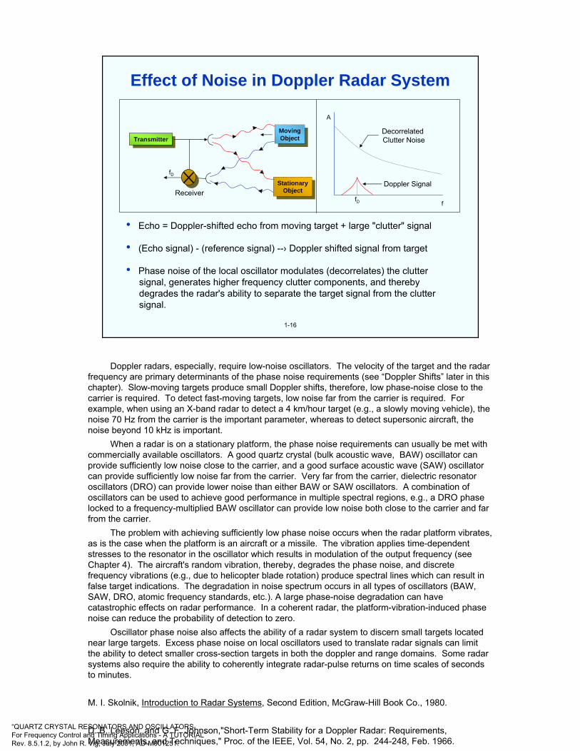
• Echo = Doppler-shifted echo from moving target + large "clutter" signal
• (Echo signal) - (reference signal) --› Doppler shifted signal from target
• Phase noise of the local oscillator modulates (decorrelates) the clutter signal, generates higher frequency clutter components, and thereby degrades the radar's ability to separate the target signal from the clutter signal.
TransmitterTransmitter
fD
ReceiverStationary
ObjectStationary
Object
MovingObject
MovingObject
ffD
Doppler Signal
DecorrelatedClutter Noise
A
Effect of Noise in Doppler Radar System
Doppler radars, especially, require low-noise oscillators. The velocity of the target and the radar frequency are primary determinants of the phase noise requirements (see “Doppler Shifts” later in this chapter). Slow-moving targets produce small Doppler shifts, therefore, low phase-noise close to the carrier is required. To detect fast-moving targets, low noise far from the carrier is required. Forexample, when using an X-band radar to detect a 4 km/hour target (e.g., a slowly moving vehicle), the noise 70 Hz from the carrier is the important parameter, whereas to detect supersonic aircraft, the noise beyond 10 kHz is important.
When a radar is on a stationary platform, the phase noise requirements can usually be met with commercially available oscillators. A good quartz crystal (bulk acoustic wave, BAW) oscillator can provide sufficiently low noise close to the carrier, and a good surface acoustic wave (SAW) oscillator can provide sufficiently low noise far from the carrier. Very far from the carrier, dielectric resonator oscillators (DRO) can provide lower noise than either BAW or SAW oscillators. A combination of oscillators can be used to achieve good performance in multiple spectral regions, e.g., a DRO phase locked to a frequency-multiplied BAW oscillator can provide low noise both close to the carrier and far from the carrier.
The problem with achieving sufficiently low phase noise occurs when the radar platform vibrates, as is the case when the platform is an aircraft or a missile. The vibration applies time-dependent stresses to the resonator in the oscillator which results in modulation of the output frequency (see Chapter 4). The aircraft's random vibration, thereby, degrades the phase noise, and discrete frequency vibrations (e.g., due to helicopter blade rotation) produce spectral lines which can result in false target indications. The degradation in noise spectrum occurs in all types of oscillators (BAW, SAW, DRO, atomic frequency standards, etc.). A large phase-noise degradation can have catastrophic effects on radar performance. In a coherent radar, the platform-vibration-induced phase noise can reduce the probability of detection to zero.
Oscillator phase noise also affects the ability of a radar system to discern small targets located near large targets. Excess phase noise on local oscillators used to translate radar signals can limit the ability to detect smaller cross-section targets in both the doppler and range domains. Some radar systems also require the ability to coherently integrate radar-pulse returns on time scales of seconds to minutes.
M. I. Skolnik, Introduction to Radar Systems, Second Edition, McGraw-Hill Book Co., 1980.
D. B. Leeson, and G. F. Johnson,"Short-Term Stability for a Doppler Radar: Requirements, Measurements, and Techniques," Proc. of the IEEE, Vol. 54, No. 2, pp. 244-248, Feb. 1966.
“QUARTZ CRYSTAL RESONATORS AND OSCILLATORSFor Frequency Control and Timing Applications - A TUTORIAL”Rev. 8.5.1.2, by John R. Vig, July 2001, AD-M001251.
1-17
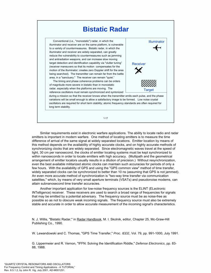
Conventional (i.e., "monostatic") radar, in which the illuminator and receiver are on the same platform, is vulnerableto a variety of countermeasures. Bistatic radar, in which the illuminator and receiver are widely separated, can greatly reduce the vulnerability to countermeasures such as jamming and antiradiation weapons, and can increase slow moving target detection and identification capability via "clutter tuning”(receiver maneuvers so that its motion compensates for the motion of the illuminator; creates zero Doppler shift for the area being searched). The transmitter can remain far from the battlearea, in a "sanctuary." The receiver can remain "quiet.”
The timing and phase coherence problems can be ordersof magnitude more severe in bistatic than in monostatic radar, especially when the platforms are moving. The reference oscillators must remain synchronized and syntonized during a mission so that the receiver knows when the transmitter emits each pulse, and the phase variations will be small enough to allow a satisfactory image to be formed. Low noise crystal oscillators are required for short term stability; atomic frequency standards are often required for long term stability.
Receiver
Illuminator
Target
Bistatic Radar
Similar requirements exist in electronic warfare applications. The ability to locate radio and radar emitters is important in modern warfare. One method of locating emitters is to measure the time difference of arrival of the same signal at widely separated locations. Emitter location by means of this method depends on the availability of highly accurate clocks, and on highly accurate methods of synchronizing clocks that are widely separated. Since electromagnetic waves travel at the speed of light, 30 cm per nanosecond, the clocks of emitter locating systems must be kept synchronized to within nanoseconds in order to locate emitters with high accuracy. (Multipath and the geometrical arrangement of emitter locators usually results in a dilution of precision.) Without resynchronization, even the best available militarized atomic clocks can maintain such accuracies for periods of only a few hours. With the availability of GPS and using the "GPS common view" method of time transfer, widely separated clocks can be synchronized to better than 10 ns (assuming that GPS is not jammed). An even more accurate method of synchronization is "two-way time transfer via communication satellites," which, by means of very small aperture terminals (VSATs) and pseudonoise modems, can attain subnanosecond time transfer accuracies.
Another important application for low-noise frequency sources is the ELINT (ELectronicINTelligence) receiver. These receivers are used to search a broad range of frequencies for signals that may be emitted by a potential adversary. The frequency source must be as noise-free as possible so as not to obscure weak incoming signals. The frequency source must also be extremely stable and accurate in order to allow accurate measurement of the incoming signal's characteristics.
N. J. Willis, "Bistatic Radar," in Radar Handbook, M. I. Skolnik, editor, Chapter 25, Mc-Graw-Hill Publishing Co., 1990.
W. Lewandowski and C. Thomas, "GPS Time Transfer," Proc. IEEE, Vol. 79, pp. 991-1000, July 1991.
G. Lippermeier and R. Vernon, "IFFN: Solving the Identification Riddle," Defense Electronics, pp. 83-88, 1988.

“QUARTZ CRYSTAL RESONATORS AND OSCILLATORSFor Frequency Control and Timing Applications - A TUTORIAL”Rev. 8.5.1.2, by John R. Vig, July 2001, AD-M001251.
1-18
Doppler Shift for Target Moving Toward Fixed Radar (Hz)
5
0
10
15
20
25
30
40
10 100 1K 10K 100K 1M
Rad
a r F
requ
ency
(GH
z)
4km
/h -
Man
or S
low
Mov
ing
Vech
ile
100k
m/h
-Ve
hicl
e, G
roun
d or
Air
700k
m/h
-Su
bson
ic A
ircra
ft2,
400
km/h
-M
ach
2 Ai
rcra
ft
X-Band RADAR
Doppler Shifts
Doppler radars require low-phase-noise oscillators. The velocity of the target and the radar frequency are the primary factors that determine the oscillator noise requirements. For example, to detect slow-moving targets, the noise close to the carrier must be low.
The Doppler shift* of an object moving towards the observer is given by ∆f/f = 2v/c, where ∆f is the Doppler frequency shift, v is the velocity of the object, and c is the speed of light.
* Doppler shift example: if v = 4 km/h and f = 10 GHz (e.g., a slow-moving vehicle approaching an X-band radar), then ∆f = 74 Hz, i.e., an oscillator with low phase noise at 74Hz from the carrier is necessary in order for a coherent radar system to "see" the vehicle.

“QUARTZ CRYSTAL RESONATORS AND OSCILLATORSFor Frequency Control and Timing Applications - A TUTORIAL”Rev. 8.5.1.2, by John R. Vig, July 2001, AD-M001251.
2
CHAPTER 2Quartz Crystal Oscillators
W. L. Smith, "Precision Oscillators," in E. A. Gerber and A. Ballato, Precision Frequency Control, Vol. 2, pp. 45-98, Academic Press, 1985.
B. Parzen, Design of Crystal and Other Harmonic Oscillators, John Wiley and Sons, Inc., 1983.
M. E. Frerking, "Temperature Control and Compensation," in E. A. Gerber and A. Ballato, Precision Frequency Control, Vol. 2, pp. 99-111, Academic Press, 1985.
M. E. Frerking, Crystal Oscillator Design and Temperature Compensation, Van Nostrand Reinhold Co., 1978.
Hewlett-Packard Co., Test & Measurement Application Notes <http://www.tmo.hp.com/tmo/Notes/English/Oscillators.html>
"Fundamentals of Quartz Oscillators," Hewlett-Packard Application Note AN 200-2, Hewlett-Packard Company.
A. Benjaminson, "Computer-Aided Design of Crystal Oscillators," U. S. Army R & D Technical Report DELET-TR-84-0386-F, August 1985, AD-B096820; "Advanced Crystal Oscillator Design," U. S. Army R & D Technical Report SLCET-TR-85-0445-F, January 1988, AD-B121288; "Advanced Crystal Oscillator Design," U. S. Army R & D Technical Report SLCET-TR-88-0804-1, February 1989, AD-B134514; "Advanced Crystal Oscillator Design," U. S. Army R & D Technical Report SLCET-TR-88-0804-F, December 1991, AD-B163808.

“QUARTZ CRYSTAL RESONATORS AND OSCILLATORSFor Frequency Control and Timing Applications - A TUTORIAL”Rev. 8.5.1.2, by John R. Vig, July 2001, AD-M001251.
TuningVoltage
Crystalresonator
Amplifier
OutputFrequency
2-1
Crystal Oscillator
Above is a simplified circuit diagram that shows the basic elements of a crystal oscillator (XO). The amplifier of an XO consists of at least one active device, the necessary biasing networks, and may include other elements for band limiting, impedance matching, and gain control. The feedback network consists of the crystal resonator, and may contain other elements, such as a variable capacitor for tuning.
W. L. Smith, "Precision Oscillators," in E. A. Gerber and A. Ballato, Precision Frequency Control, Vol. 2, pp. 45-98, Academic Press, 1985.
B. Parzen, Design of Crystal and Other Harmonic Oscillators, John Wiley and Sons, Inc., 1983.
M. E. Frerking, "Temperature Control and Compensation," in E. A. Gerber and A. Ballato, Precision Frequency Control, Vol. 2, pp. 99-111, Academic Press, 1985.
M. E. Frerking, Crystal Oscillator Design and Temperature Compensation, Van Nostrand Reinhold Company, 1978.
"Fundamentals of Quartz Oscillators," Hewlett-Packard application note AN 200-2, Hewlett-Packard Company, <http://www.tmo.hp.com/@@2ZcNpBcQ240oRhrt/tmo/Notes/English/5965-7662E.html>
“QUARTZ CRYSTAL RESONATORS AND OSCILLATORSFor Frequency Control and Timing Applications - A TUTORIAL”Rev. 8.5.1.2, by John R. Vig, July 2001, AD-M001251.
2-2
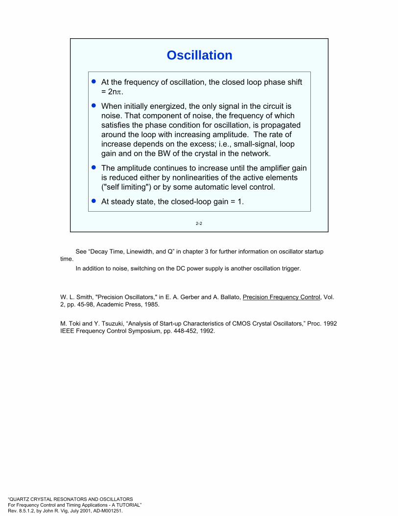
• At the frequency of oscillation, the closed loop phase shift = 2nπ.
• When initially energized, the only signal in the circuit is noise. That component of noise, the frequency of which satisfies the phase condition for oscillation, is propagated around the loop with increasing amplitude. The rate of increase depends on the excess; i.e., small-signal, loop gain and on the BW of the crystal in the network.
• The amplitude continues to increase until the amplifier gain is reduced either by nonlinearities of the active elements ("self limiting") or by some automatic level control.
• At steady state, the closed-loop gain = 1.
Oscillation
See “Decay Time, Linewidth, and Q” in chapter 3 for further information on oscillator startup time.
In addition to noise, switching on the DC power supply is another oscillation trigger.
W. L. Smith, "Precision Oscillators," in E. A. Gerber and A. Ballato, Precision Frequency Control, Vol. 2, pp. 45-98, Academic Press, 1985.
M. Toki and Y. Tsuzuki, “Analysis of Start-up Characteristics of CMOS Crystal Oscillators,” Proc. 1992 IEEE Frequency Control Symposium, pp. 448-452, 1992.
“QUARTZ CRYSTAL RESONATORS AND OSCILLATORSFor Frequency Control and Timing Applications - A TUTORIAL”Rev. 8.5.1.2, by John R. Vig, July 2001, AD-M001251.
2-3
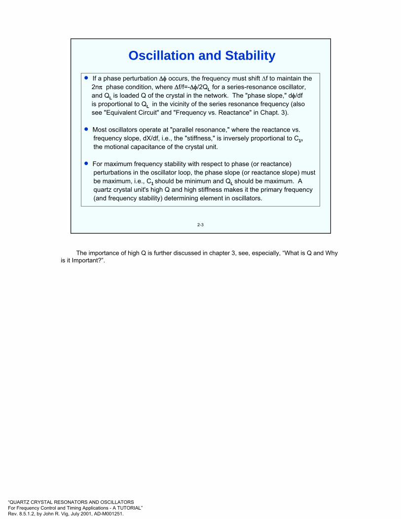
• If a phase perturbation ∆φ occurs, the frequency must shift ∆f to maintain the 2nπ phase condition, where ∆f/f=-∆φ/2QL for a series-resonance oscillator,and QL is loaded Q of the crystal in the network. The "phase slope," dφ/df is proportional to QL in the vicinity of the series resonance frequency (alsosee "Equivalent Circuit" and "Frequency vs. Reactance" in Chapt. 3).
• Most oscillators operate at "parallel resonance," where the reactance vs.frequency slope, dX/df, i.e., the "stiffness," is inversely proportional to C1,the motional capacitance of the crystal unit.
• For maximum frequency stability with respect to phase (or reactance)perturbations in the oscillator loop, the phase slope (or reactance slope) must be maximum, i.e., C1 should be minimum and QL should be maximum. Aquartz crystal unit's high Q and high stiffness makes it the primary frequency(and frequency stability) determining element in oscillators.
Oscillation and Stability
The importance of high Q is further discussed in chapter 3, see, especially, “What is Q and Why is it Important?”.
“QUARTZ CRYSTAL RESONATORS AND OSCILLATORSFor Frequency Control and Timing Applications - A TUTORIAL”Rev. 8.5.1.2, by John R. Vig, July 2001, AD-M001251.
2-4
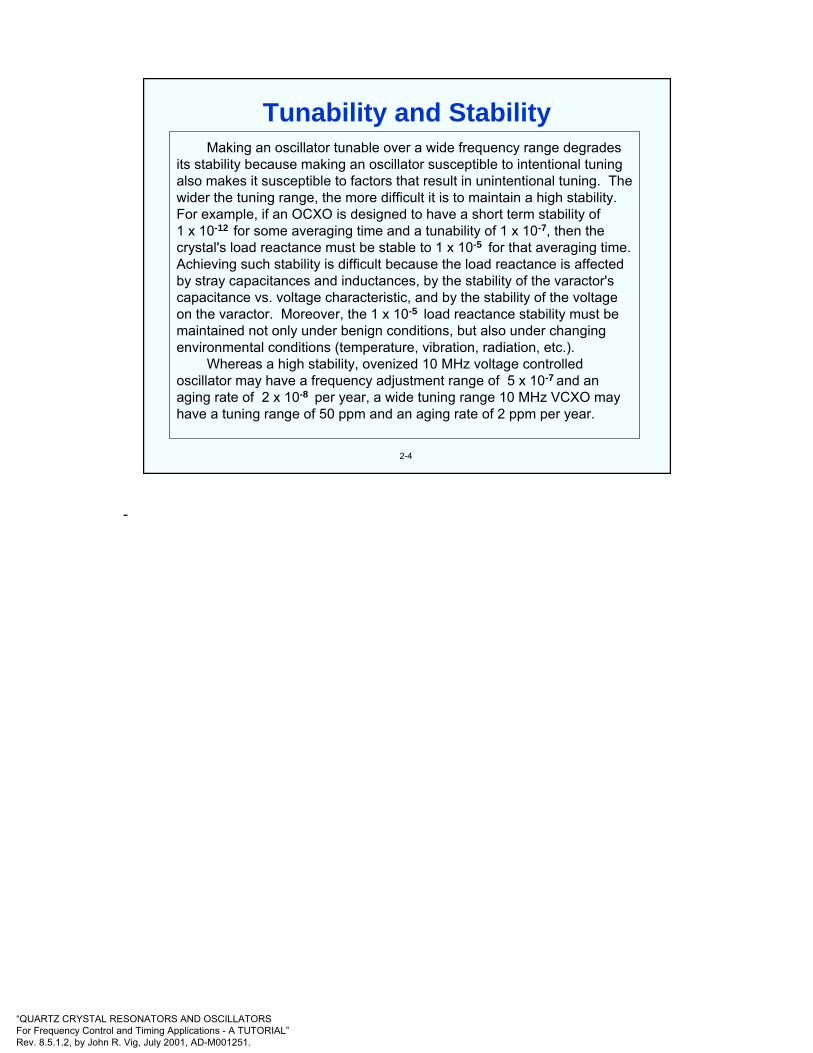
Making an oscillator tunable over a wide frequency range degrades its stability because making an oscillator susceptible to intentional tuning also makes it susceptible to factors that result in unintentional tuning. The wider the tuning range, the more difficult it is to maintain a high stability. For example, if an OCXO is designed to have a short term stability of 1 x 10-12 for some averaging time and a tunability of 1 x 10⁻⁷, then the crystal's load reactance must be stable to 1 x 10⁻⁵ for that averaging time. Achieving such stability is difficult because the load reactance is affected by stray capacitances and inductances, by the stability of the varactor's capacitance vs. voltage characteristic, and by the stability of the voltage on the varactor. Moreover, the 1 x 10⁻⁵ load reactance stability must be maintained not only under benign conditions, but also under changing environmental conditions (temperature, vibration, radiation, etc.).
Whereas a high stability, ovenized 10 MHz voltage controlled oscillator may have a frequency adjustment range of 5 x 10⁻⁷ and an aging rate of 2 x 10⁻⁸ per year, a wide tuning range 10 MHz VCXO may have a tuning range of 50 ppm and an aging rate of 2 ppm per year.
Tunability and Stability
-
“QUARTZ CRYSTAL RESONATORS AND OSCILLATORSFor Frequency Control and Timing Applications - A TUTORIAL”Rev. 8.5.1.2, by John R. Vig, July 2001, AD-M001251.
2-5
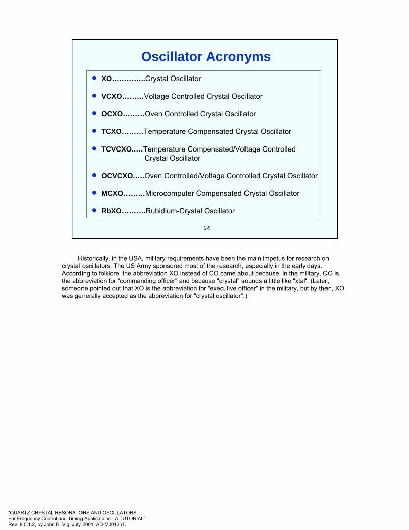
• XO…………..Crystal Oscillator
• VCXO………Voltage Controlled Crystal Oscillator
• OCXO………Oven Controlled Crystal Oscillator
• TCXO………Temperature Compensated Crystal Oscillator
• TCVCXO..…Temperature Compensated/Voltage ControlledCrystal Oscillator
• OCVCXO.….Oven Controlled/Voltage Controlled Crystal Oscillator
• MCXO………Microcomputer Compensated Crystal Oscillator
• RbXO……….Rubidium-Crystal Oscillator
Oscillator Acronyms
Historically, in the USA, military requirements have been the main impetus for research on crystal oscillators. The US Army sponsored most of the research, especially in the early days. According to folklore, the abbreviation XO instead of CO came about because, in the military, CO is the abbreviation for "commanding officer" and because "crystal" sounds a little like "xtal". (Later, someone pointed out that XO is the abbreviation for "executive officer" in the military, but by then, XO was generally accepted as the abbreviation for "crystal oscillator".)

“QUARTZ CRYSTAL RESONATORS AND OSCILLATORSFor Frequency Control and Timing Applications - A TUTORIAL”Rev. 8.5.1.2, by John R. Vig, July 2001, AD-M001251.
2-6
The three categories, based on the method of dealing with the crystal unit'sfrequency vs. temperature (f vs. T) characteristic, are:
• XO, crystal oscillator, does not contain means for reducing the crystal's f vs. T characteristic (also called PXO-packaged crystal oscillator).
• TCXO, temperature compensated crystal oscillator, in which, e.g., the output signal from a temperature sensor (e.g., a thermistor) is used to generate a correction voltage that is applied to a variable reactance (e.g., a varactor) in the crystal network. The reactance variations compensate for the crystal's f vs. T characteristic. Analog TCXO's can provide about a 20X improvement over the crystal's f vs. T variation.
• OCXO, oven controlled crystal oscillator, in which the crystal and othertemperature sensitive components are in a stable oven which is adjusted to the temperature where the crystal's f vs. T has zero slope. OCXO's can provide a >1000X improvement over the crystal's f vs. T variation.
Crystal Oscillator Categories
-

“QUARTZ CRYSTAL RESONATORS AND OSCILLATORSFor Frequency Control and Timing Applications - A TUTORIAL”Rev. 8.5.1.2, by John R. Vig, July 2001, AD-M001251.
2-7
TemperatureSensor
TemperatureSensor Compensation
Network orComputer
CompensationNetwork orComputer
XOXO
• Temperature Compensated (TCXO)
-450Cff∆
+1 ppm
-1 ppm
+1000CT
OvencontrolOven
controlXOXO
TemperatureSensor
TemperatureSensor
Oven
• Oven Controlled (OCXO)
-450C ff∆
+1 x 10⁻⁸
-1 x 10⁻⁸
+1000CT
VoltageTune
Output
• Crystal Oscillator (XO)
-450C
-10 ppm
+10 ppm250C
T+1000C
ff∆
Crystal Oscillator Categories
A wide temperature range XO has a typical f vs. T stability of ~10 to 50 ppm. A TCXO can reduce that to ~1 ppm. An OCXO can reduce that stability to 1 x 10⁻⁸ or better (but at the cost of much higher power consumption). High-end (SC-cut) OCXOs can stay within 1 x 10⁻¹⁰ over a wide temperature range.
“QUARTZ CRYSTAL RESONATORS AND OSCILLATORSFor Frequency Control and Timing Applications - A TUTORIAL”Rev. 8.5.1.2, by John R. Vig, July 2001, AD-M001251.
2-8
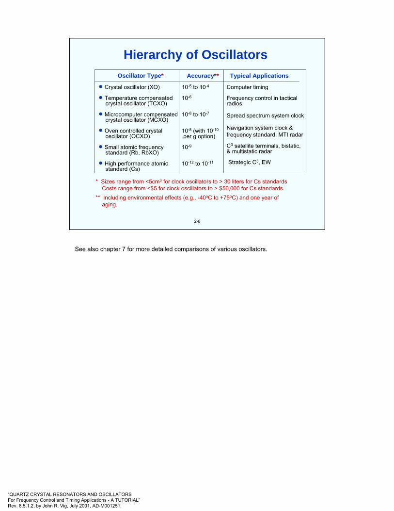
Oscillator Type*
• Crystal oscillator (XO)
• Temperature compensatedcrystal oscillator (TCXO)
• Microcomputer compensatedcrystal oscillator (MCXO)
• Oven controlled crystaloscillator (OCXO)
• Small atomic frequencystandard (Rb, RbXO)
• High performance atomicstandard (Cs)
Typical Applications
Computer timing
Frequency control in tacticalradios
Spread spectrum system clock
Navigation system clock &frequency standard, MTI radar
C3 satellite terminals, bistatic,& multistatic radar
Strategic C3, EW
Accuracy**
10-5 to 10-4
10-6
10-8 to 10-7
10-8 (with 10-10
per g option)
10-9
10-12 to 10-11
* Sizes range from <5cm3 for clock oscillators to > 30 liters for Cs standardsCosts range from <$5 for clock oscillators to > $50,000 for Cs standards.
** Including environmental effects (e.g., -40oC to +75oC) and one year of aging.
Hierarchy of Oscillators
See also chapter 7 for more detailed comparisons of various oscillators.

“QUARTZ CRYSTAL RESONATORS AND OSCILLATORSFor Frequency Control and Timing Applications - A TUTORIAL”Rev. 8.5.1.2, by John R. Vig, July 2001, AD-M001251.
2-9
Of the numerous oscillator circuit types, three of the more common ones, the Pierce, the Colpitts and the Clapp, consist of the same circuit except that the rf ground points are at different locations. The Butler and modified Butler are also similar to each other; in each, the emitter current is the crystal current. The gate oscillator is a Pierce-type that uses a logic gate plus a resistor in place of the transistor in the Pierce oscillator. (Some gate oscillators use more than one gate).
Pierce Colpitts Clapp
GateModified ButlerButler
b c∈
b
c∈
bc∈
b
c∈ b c
∈
Oscillator Circuit Types
The choice of oscillator circuit type depends on factors such as the desired frequency stability, input voltage and power, output power and waveform, tunability, design complexity, cost and the crystal unit's characteristics.
In the Pierce family, the ground point location has a profound effect on the performance. The Pierce configuration is generally superior to the others, e.g., with respect to the effects of stray reactances and biasing resistors, which appear mostly across the capacitors in the circuit rather than the crystal unit. It is one of the most widely used circuits for high stability oscillators. In the Colpitts configuration, a larger part of the strays appears across the crystal, and the biasing resistors are also across the crystal, which can degrade performance. The Clapp is seldom used because, since the collector is tied directly to the crystal, it is difficult to apply a dc voltage to the collector without introducing losses or spurious oscillations. (See the references for more details.)
The Pierce family usually operates at "parallel resonance" (see "Resonator Frequency vs. Reactance" in Chapt. 3), although it can be designed to operate at series resonance by connecting an inductor in series with the crystal. The Butler family usually operates at (or near) series resonance. The Pierce can be designed to operate with the crystal current above or below the emitter current.
Gate oscillators are common in digital systems when high stability is not a major consideration.
A. Benjaminson, "Computer-Aided Design of Crystal Oscillators," U. S. Army R & D Technical Report DELET-TR-84- 0386-F, August 1985, AD-B096820; "Advanced Crystal Oscillator Design," U. S. Army R & D Technical Report SLCET-TR-85-0445-F, January 1988, AD-B121288; "Advanced Crystal Oscillator Design," U. S. Army R & D Technical Report SLCET-TR-88-0804-1, February 1989, AD-B134514; "Advanced Crystal Oscillator Design," U. S. Army R & D Technical Report SLCET-TR-88-0804-F, December 1991, AD-B163808.
J. P. Buchanan, Handbook of Piezoelectric Crystals for Radio Equipment Designers, WADC Technical Report 56-156, October 1956 (692 pages), available from NTIS, AD 110448.

“QUARTZ CRYSTAL RESONATORS AND OSCILLATORSFor Frequency Control and Timing Applications - A TUTORIAL”Rev. 8.5.1.2, by John R. Vig, July 2001, AD-M001251.
ϕOutput
Oven
2-10
Each of the three main parts of an OCXO, i.e., the crystal, the sustainingcircuit, and the oven, contribute to instabilities. The various instabilities are discussed in the rest of chapter 3 and in chapter 4.
OCXO Block Diagram
F. L. Walls & J. R. Vig, "Fundamental Limits on the Frequency Stabilities of Quartz Crystal Oscillators," IEEE Transactions on Ultrasonics, Ferroelectrics, and Frequency Control, vol. 42, pp. 576-589, July 1995.
F. L. Walls & J.-J. Gagnepain, "Environmental Sensitivities of Quartz Oscillators, IEEE Trans. Ultrasonics, Ferroelectrics and Frequency Control, vol. 39, pp. 241-249, 1992.
“QUARTZ CRYSTAL RESONATORS AND OSCILLATORSFor Frequency Control and Timing Applications - A TUTORIAL”Rev. 8.5.1.2, by John R. Vig, July 2001, AD-M001251.
2-11
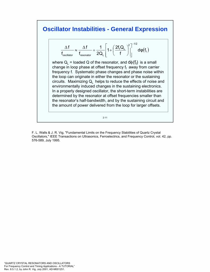
where QL = loaded Q of the resonator, and dφ(ff) is a smallchange in loop phase at offset frequency ff away from carrierfrequency f. Systematic phase changes and phase noise withinthe loop can originate in either the resonator or the sustainingcircuits. Maximizing QL helps to reduce the effects of noise andenvironmentally induced changes in the sustaining electronics.In a properly designed oscillator, the short-term instabilities aredetermined by the resonator at offset frequencies smaller thanthe resonator’s half-bandwidth, and by the sustaining circuit andthe amount of power delivered from the loop for larger offsets.
( )f
1/22Lf
Lresonatoroscillator
fdφfQ2f1
2Q1
ff
ff
−
⎥⎥⎦
⎤
⎢⎢⎣
⎡⎟⎠⎞
⎜⎝⎛++≈
∆∆
Oscillator Instabilities - General Expression
F. L. Walls & J. R. Vig, "Fundamental Limits on the Frequency Stabilities of Quartz Crystal Oscillators," IEEE Transactions on Ultrasonics, Ferroelectrics, and Frequency Control, vol. 42, pp. 576-589, July 1995.
“QUARTZ CRYSTAL RESONATORS AND OSCILLATORSFor Frequency Control and Timing Applications - A TUTORIAL”Rev. 8.5.1.2, by John R. Vig, July 2001, AD-M001251.
2-12
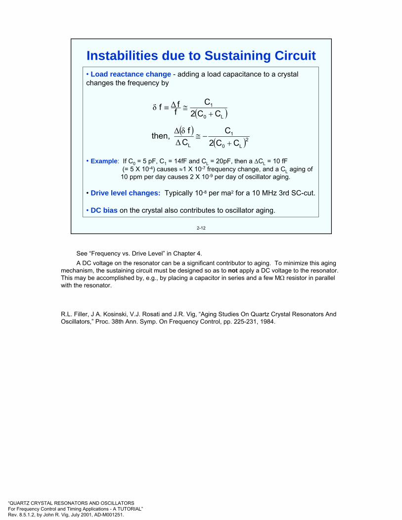
• Load reactance change - adding a load capacitance to a crystal changes the frequency by
• Example: If C0 = 5 pF, C1 = 14fF and CL = 20pF, then a ∆CL = 10 fF(= 5 X 10⁻⁴) causes ≈1 X 10⁻⁷ frequency change, and a CL aging of
10 ppm per day causes 2 X 10⁻⁹ per day of oscillator aging.
• Drive level changes: Typically 10-8 per ma2 for a 10 MHz 3rd SC-cut.
• DC bias on the crystal also contributes to oscillator aging.
( )( )
( )2L0
1
L
L0
1
CC2C
Cf then,
CC2C
fff
+−≅
+≅≡
∆δ∆
∆δ
Instabilities due to Sustaining Circuit
See “Frequency vs. Drive Level” in Chapter 4.A DC voltage on the resonator can be a significant contributor to aging. To minimize this aging
mechanism, the sustaining circuit must be designed so as to not apply a DC voltage to the resonator. This may be accomplished by, e.g., by placing a capacitor in series and a few MΩ resistor in parallel with the resonator.
R.L. Filler, J A. Kosinski, V.J. Rosati and J.R. Vig, “Aging Studies On Quartz Crystal Resonators And Oscillators,” Proc. 38th Ann. Symp. On Frequency Control, pp. 225-231, 1984.
“QUARTZ CRYSTAL RESONATORS AND OSCILLATORSFor Frequency Control and Timing Applications - A TUTORIAL”Rev. 8.5.1.2, by John R. Vig, July 2001, AD-M001251.
2-13
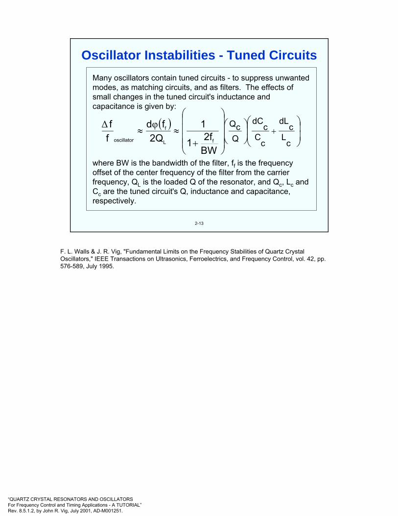
Many oscillators contain tuned circuits - to suppress unwanted modes, as matching circuits, and as filters. The effects of small changes in the tuned circuit's inductance and capacitance is given by:
where BW is the bandwidth of the filter, ff is the frequency offset of the center frequency of the filter from the carrier frequency, QL is the loaded Q of the resonator, and Qc, Lc and Cc are the tuned circuit's Q, inductance and capacitance, respectively.
( )⎟⎟⎠
⎞⎜⎜⎝
⎛⎟⎠
⎞⎜⎝
⎛
⎟⎟⎟⎟
⎠
⎞
⎜⎜⎜⎜
⎝
⎛
+≈≈ +
cL
cdL
cC
cdC
QcQ
BW2f1
12Q
fdff
fL
f
oscillator
φ∆
Oscillator Instabilities - Tuned Circuits
F. L. Walls & J. R. Vig, "Fundamental Limits on the Frequency Stabilities of Quartz Crystal Oscillators," IEEE Transactions on Ultrasonics, Ferroelectrics, and Frequency Control, vol. 42, pp. 576-589, July 1995.
“QUARTZ CRYSTAL RESONATORS AND OSCILLATORSFor Frequency Control and Timing Applications - A TUTORIAL”Rev. 8.5.1.2, by John R. Vig, July 2001, AD-M001251.
2-14
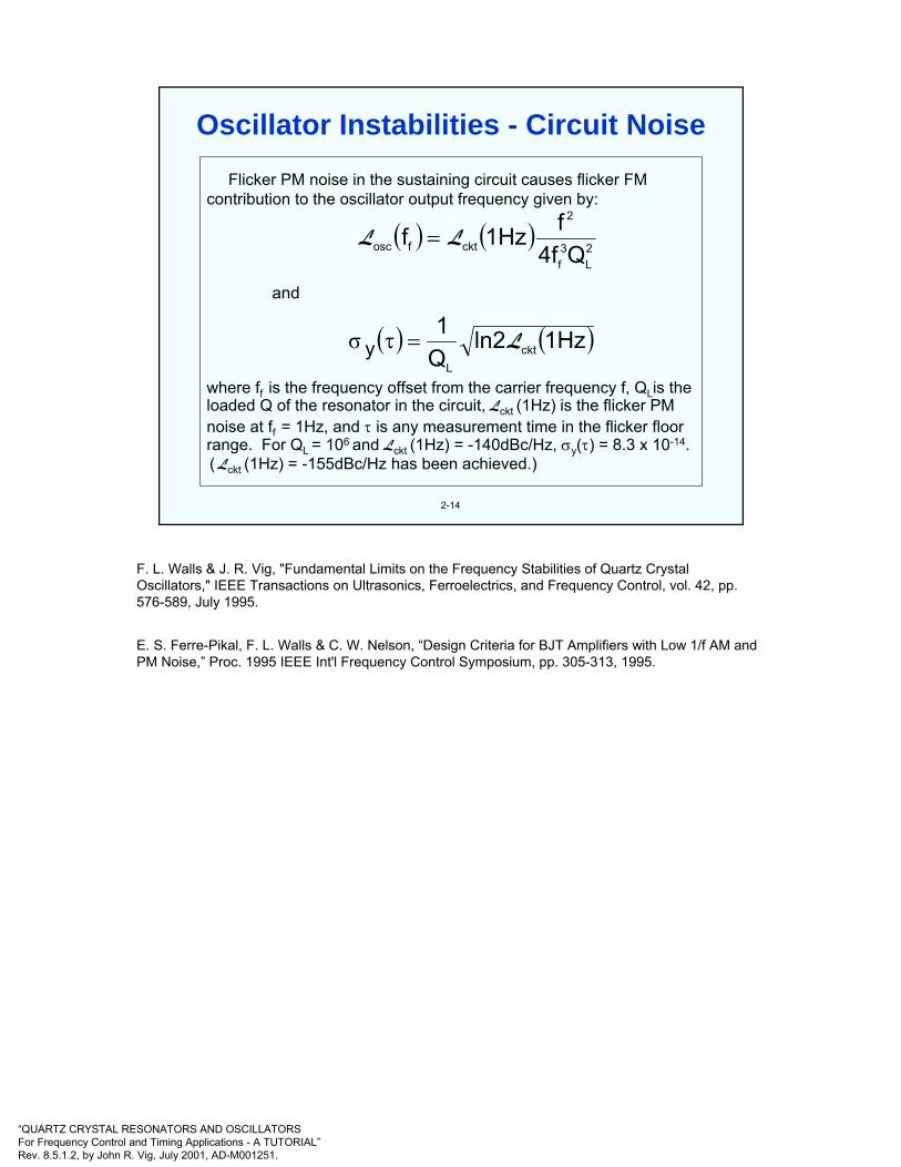
Flicker PM noise in the sustaining circuit causes flicker FMcontribution to the oscillator output frequency given by:
where ff is the frequency offset from the carrier frequency f, QLis the loaded Q of the resonator in the circuit, Lckt (1Hz) is the flicker PM noise at ff = 1Hz, and τ is any measurement time in the flicker floor range. For QL = 106 and Lckt (1Hz) = -140dBc/Hz, σy(τ) = 8.3 x 10⁻¹⁴.( Lckt (1Hz) = -155dBc/Hz has been achieved.)
( ) ( )
( ) ( )1Hzln2Q1
Q4ff1Hzf
cktL
2L
3f
2
cktfosc
y
and
L
LL
=τ
=
σ
Oscillator Instabilities - Circuit Noise
F. L. Walls & J. R. Vig, "Fundamental Limits on the Frequency Stabilities of Quartz Crystal Oscillators," IEEE Transactions on Ultrasonics, Ferroelectrics, and Frequency Control, vol. 42, pp. 576-589, July 1995.
E. S. Ferre-Pikal, F. L. Walls & C. W. Nelson, “Design Criteria for BJT Amplifiers with Low 1/f AM and PM Noise,” Proc. 1995 IEEE Int'l Frequency Control Symposium, pp. 305-313, 1995.

“QUARTZ CRYSTAL RESONATORS AND OSCILLATORSFor Frequency Control and Timing Applications - A TUTORIAL”Rev. 8.5.1.2, by John R. Vig, July 2001, AD-M001251.
2-15
If the external load changes, there is a change in the amplitudeor phase of the signal reflected back into the oscillator. Theportion of that signal which reaches the oscillating loop changesthe oscillation phase, and hence the frequency by
where Γ is the VSWR of the load, and θ is the phase angle of the reflected wave; e.g., if Q ~ 106, and isolation ~40 dB (i.e., ~10-4), then the worst case (100% reflection) pulling is~5 x 10⁻⁹. A VSWR of 2 reduces the maximum pulling by onlya factor of 3. The problem of load pulling becomes worse at higher frequencies, because both the Q and the isolation are lower.
( ) ( ) isolationsin11
2Q1
2Qfd
ff f
oscillatorθ
ΓΓ∆
⎟⎠⎞
⎜⎝⎛
+−
⎟⎠⎞
⎜⎝⎛≈
φ≈
Oscillator Instabilities - External Load
F. L. Walls & J. R. Vig, "Fundamental Limits on the Frequency Stabilities of Quartz Crystal Oscillators," IEEE Transactions on Ultrasonics, Ferroelectrics, and Frequency Control, vol. 42, pp. 576-589, July 1995.

“QUARTZ CRYSTAL RESONATORS AND OSCILLATORSFor Frequency Control and Timing Applications - A TUTORIAL”Rev. 8.5.1.2, by John R. Vig, July 2001, AD-M001251.
2-16
Most users require a sine wave, a TTL-compatible, a CMOS-compatible, or an ECL-compatible output. The latter three can be simply generated from a sine wave. The four output types are illustrated below, with the dashed lines representing the supplyvoltage inputs, and the bold solid lines, the outputs. (There is no “standard” input voltage for sine wave oscillators. The input voltages for CMOS typically range from 1V to 10V.)
+15V
+10V
+5V
0V
-5V
Sine TTL CMOS ECL
Oscillator Outputs
-
“QUARTZ CRYSTAL RESONATORS AND OSCILLATORSFor Frequency Control and Timing Applications - A TUTORIAL”Rev. 8.5.1.2, by John R. Vig, July 2001, AD-M001251.
172300
171300
170300
-35 -15 5 25 45 65 85Temperature (oC)
fβ (Hz)
CHz/14dTdf o−=β
fβ ≡ 3f1 - f3
2-17
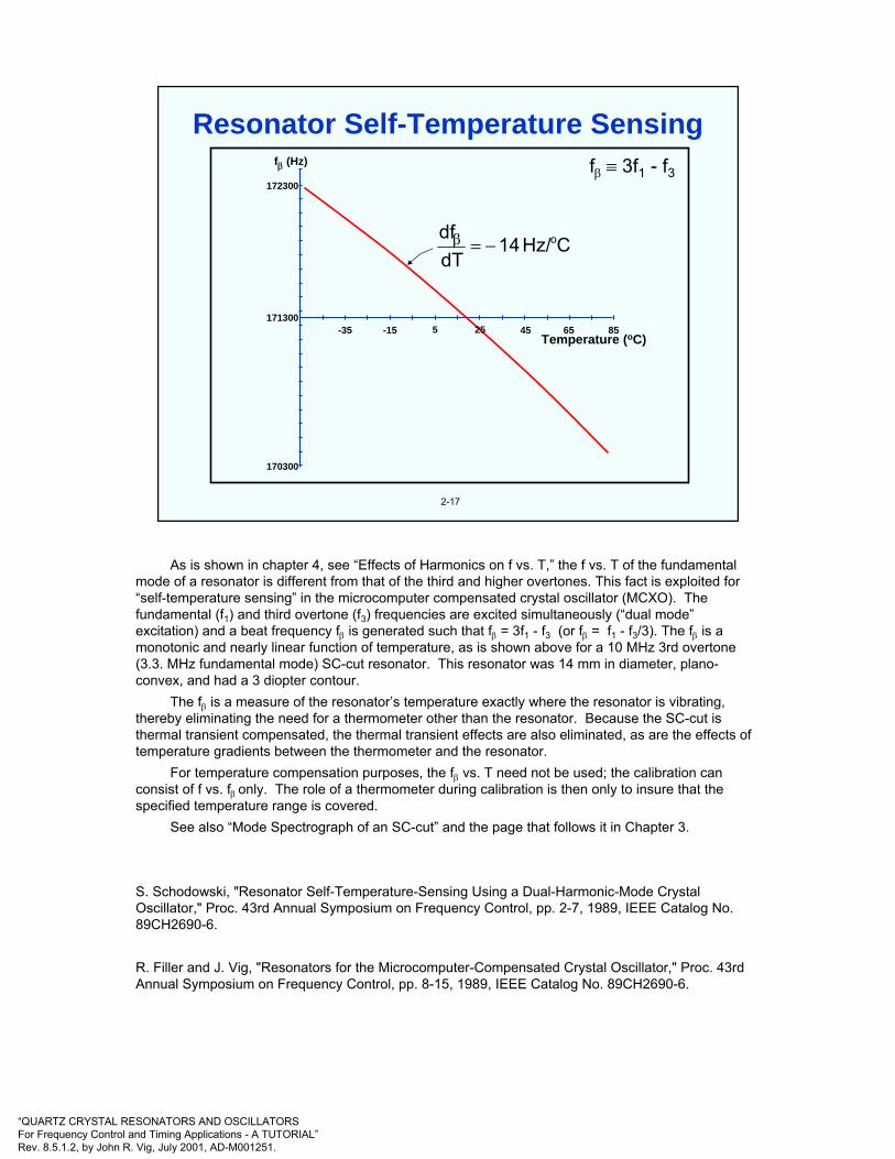
Resonator Self-Temperature Sensing
As is shown in chapter 4, see “Effects of Harmonics on f vs. T,” the f vs. T of the fundamental mode of a resonator is different from that of the third and higher overtones. This fact is exploited for “self-temperature sensing” in the microcomputer compensated crystal oscillator (MCXO). The fundamental (f1) and third overtone (f3) frequencies are excited simultaneously (“dual mode”excitation) and a beat frequency fβ is generated such that fβ = 3f1 - f3 (or fβ = f1 - f3/3). The fβ is a monotonic and nearly linear function of temperature, as is shown above for a 10 MHz 3rd overtone (3.3. MHz fundamental mode) SC-cut resonator. This resonator was 14 mm in diameter, plano-convex, and had a 3 diopter contour.
The fβ is a measure of the resonator’s temperature exactly where the resonator is vibrating, thereby eliminating the need for a thermometer other than the resonator. Because the SC-cut is thermal transient compensated, the thermal transient effects are also eliminated, as are the effects of temperature gradients between the thermometer and the resonator.
For temperature compensation purposes, the fβ vs. T need not be used; the calibration can consist of f vs. fβ only. The role of a thermometer during calibration is then only to insure that the specified temperature range is covered.
See also “Mode Spectrograph of an SC-cut” and the page that follows it in Chapter 3.
S. Schodowski, "Resonator Self-Temperature-Sensing Using a Dual-Harmonic-Mode Crystal Oscillator," Proc. 43rd Annual Symposium on Frequency Control, pp. 2-7, 1989, IEEE Catalog No. 89CH2690-6.
R. Filler and J. Vig, "Resonators for the Microcomputer-Compensated Crystal Oscillator," Proc. 43rd Annual Symposium on Frequency Control, pp. 8-15, 1989, IEEE Catalog No. 89CH2690-6.

“QUARTZ CRYSTAL RESONATORS AND OSCILLATORSFor Frequency Control and Timing Applications - A TUTORIAL”Rev. 8.5.1.2, by John R. Vig, July 2001, AD-M001251.
LOW PASSFILTER
LOW PASSFILTER
X3 MULTIPLIER
X3 MULTIPLIERM=1
M=3
f1
f3
DUAL MODEOSCILLATOR
fβ = 3f1 - f3
2-18
Mixer
Thermometric Beat Frequency Generation
The microcomputer compensated crystal oscillator (MCXO) uses a high-stability 10 MHz SC-cut quartz resonator and a dual mode oscillator which simultaneously excites the fundamental and third overtone modes of the resonator. The beat frequency may be generated either by multiplying the fundamental mode frequency by three and subtracting from it the third overtone frequency, as shown above, or by dividing the third overtone frequency by three, in which case the beat frequency is fβ = f1 -f3/3. The beat frequency is a monotonic and nearly linear function of temperature, as is shown on the previous page. It provides a high precision, digital measure of the vibrating region’s temperature, thereby eliminating the need for an external thermometer.
S. Schodowski, "Resonator Self-Temperature-Sensing Using a Dual-Harmonic-Mode Crystal Oscillator," Proc. 43rd Annual Symposium on Frequency Control, pp. 2-7, 1989, IEEE Catalog No. 89CH2690-6.

“QUARTZ CRYSTAL RESONATORS AND OSCILLATORSFor Frequency Control and Timing Applications - A TUTORIAL”Rev. 8.5.1.2, by John R. Vig, July 2001, AD-M001251.
2-19
Dual-modeXO
Dual-modeXO
x3x3
ReciprocalCounter
ReciprocalCounter
µcom-puter
µcom-puter Correction
CircuitCorrection
CircuitN1 N2
f1
f 3 fβf0
Mixer
Microcomputer Compensated Crystal Oscillator(MCXO)
The fβ is used to gate a reciprocal counter that uses the fundamental mode frequency as the time base. The counter’s output is a number N1 which varies with temperature. The microcomputer, in which f1 vs. fβ calibration information specific to each resonator is stored, solves an equation and outputs a number N2 which is used to correct for the variations of f1 with temperature.
Two correction methods have been used. In one, the SC-cut resonator is made to have a frequency that is slightly above the output frequency fo at all temperatures, and pulse deletion is used to obtain an fo that is stable over the temperature range. In the other method, the SC-cut resonator’s frequency is slightly below the output frequency fo at all temperatures, and and a correction frequency (generated by means of a direct digital synthesizer) is added to obtain an fo that is stable over the temperature range. The two methods are explained in more detail on the following pages.
S. Schodowski, "Resonator Self-Temperature-Sensing Using a Dual-Harmonic-Mode Crystal Oscillator," Proc. 43rd Annual Symposium on Frequency Control, pp. 2-7, 1989, IEEE Catalog No. 89CH2690-6.
R. Filler and J. Vig, "Resonators for the Microcomputer-Compensated Crystal Oscillator," Proc. 43rd Annual Symposium on Frequency Control, pp. 8-15, 1989, IEEE Catalog No. 89CH2690-6.
“QUARTZ CRYSTAL RESONATORS AND OSCILLATORSFor Frequency Control and Timing Applications - A TUTORIAL”Rev. 8.5.1.2, by John R. Vig, July 2001, AD-M001251.
CRYSTAL
3rd OVERTONE
DUAL-MODEOSCILLATOR
FUNDAMENTALMODE
Divide by3
COUNTER Clock
N1 out
NON-VOLATILEMEMORY
MICRO-COMPUTER
DIRECTDIGITAL
SYNTHESIZER
Divideby
4000
Divideby
2500
PHASE-LOCKED
LOOP
VCXO 10 MHzoutput
F
F
T
1 PPSoutput
T = Timing ModeF = Frequency Mode
f3 = 10 MHz -fd
f1
Mixerfb
N2Clock
ClockT
fd
Block Diagram
2-20
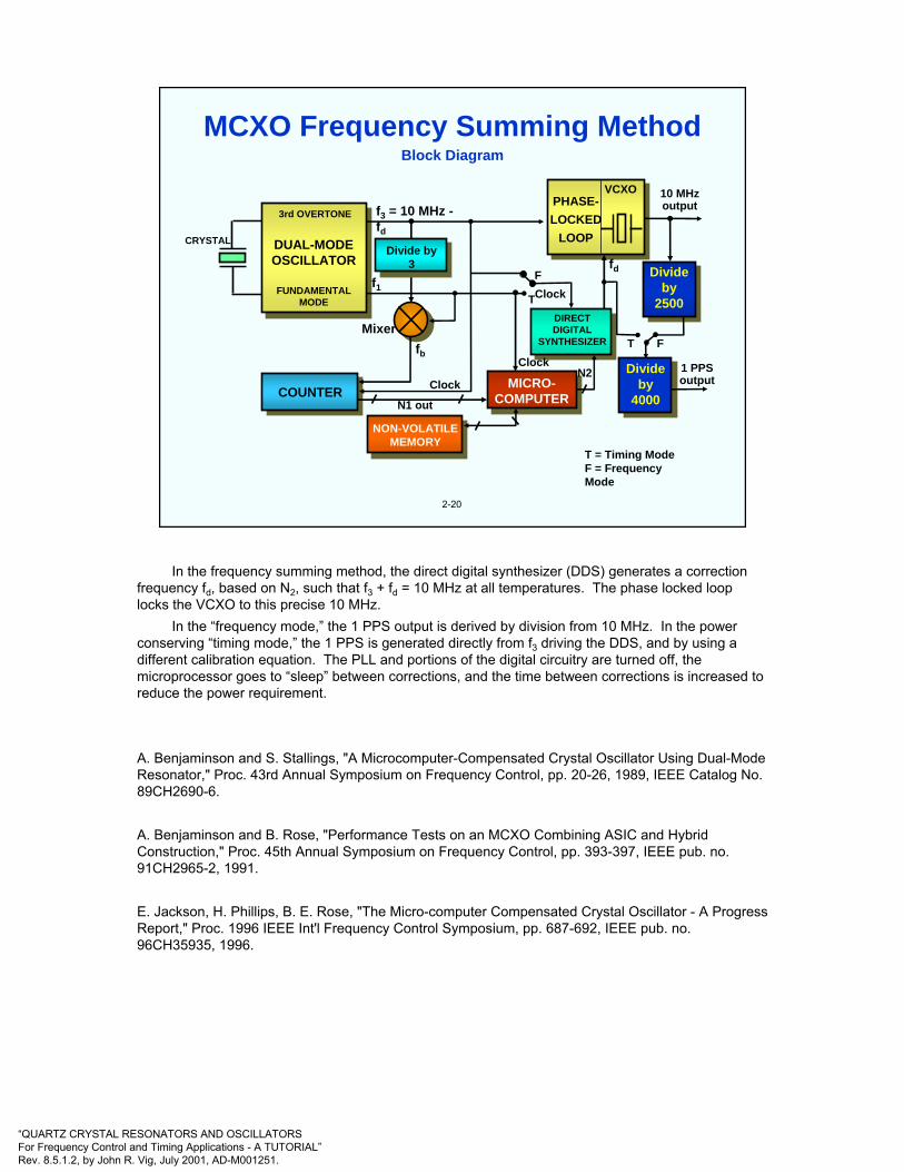
MCXO Frequency Summing Method
In the frequency summing method, the direct digital synthesizer (DDS) generates a correction frequency fd, based on N2, such that f3 + fd = 10 MHz at all temperatures. The phase locked loop locks the VCXO to this precise 10 MHz.
In the “frequency mode,” the 1 PPS output is derived by division from 10 MHz. In the power conserving “timing mode,” the 1 PPS is generated directly from f3 driving the DDS, and by using a different calibration equation. The PLL and portions of the digital circuitry are turned off, the microprocessor goes to “sleep” between corrections, and the time between corrections is increased to reduce the power requirement.
A. Benjaminson and S. Stallings, "A Microcomputer-Compensated Crystal Oscillator Using Dual-Mode Resonator," Proc. 43rd Annual Symposium on Frequency Control, pp. 20-26, 1989, IEEE Catalog No. 89CH2690-6.
A. Benjaminson and B. Rose, "Performance Tests on an MCXO Combining ASIC and Hybrid Construction," Proc. 45th Annual Symposium on Frequency Control, pp. 393-397, IEEE pub. no. 91CH2965-2, 1991.
E. Jackson, H. Phillips, B. E. Rose, "The Micro-computer Compensated Crystal Oscillator - A Progress Report," Proc. 1996 IEEE Int'l Frequency Control Symposium, pp. 687-692, IEEE pub. no. 96CH35935, 1996.
“QUARTZ CRYSTAL RESONATORS AND OSCILLATORSFor Frequency Control and Timing Applications - A TUTORIAL”Rev. 8.5.1.2, by John R. Vig, July 2001, AD-M001251.
Dual modeoscillator
Dual modeoscillator Pulse
eliminatorPulse
eliminator
Frequencyevaluator
& correctiondetermination
Frequencyevaluator
& correctiondetermination
SC-cut crystal
Digitalcircuitry (ASIC)
CounterCounter
Microprocessorcircuitry
fβ output
fc output
f0corrected
outputfor timing
Microcomputer compensated crystal oscillator (MCXO) block diagram - pulse deletion method.
2-21
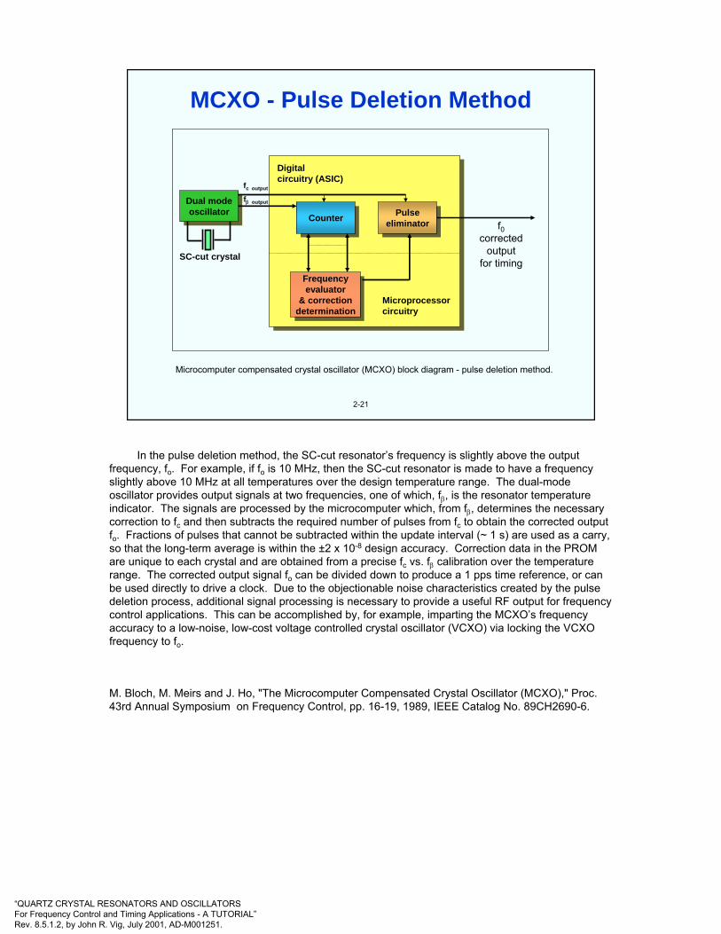
MCXO - Pulse Deletion Method
In the pulse deletion method, the SC-cut resonator’s frequency is slightly above the output frequency, fo. For example, if fo is 10 MHz, then the SC-cut resonator is made to have a frequency slightly above 10 MHz at all temperatures over the design temperature range. The dual-mode oscillator provides output signals at two frequencies, one of which, fβ, is the resonator temperature indicator. The signals are processed by the microcomputer which, from fβ, determines the necessary correction to fc and then subtracts the required number of pulses from fc to obtain the corrected output fo. Fractions of pulses that cannot be subtracted within the update interval (~ 1 s) are used as a carry, so that the long-term average is within the ±2 x 10⁻⁸ design accuracy. Correction data in the PROM are unique to each crystal and are obtained from a precise fc vs. fβ calibration over the temperature range. The corrected output signal fo can be divided down to produce a 1 pps time reference, or can be used directly to drive a clock. Due to the objectionable noise characteristics created by the pulse deletion process, additional signal processing is necessary to provide a useful RF output for frequency control applications. This can be accomplished by, for example, imparting the MCXO’s frequency accuracy to a low-noise, low-cost voltage controlled crystal oscillator (VCXO) via locking the VCXO frequency to fo.
M. Bloch, M. Meirs and J. Ho, "The Microcomputer Compensated Crystal Oscillator (MCXO)," Proc. 43rd Annual Symposium on Frequency Control, pp. 16-19, 1989, IEEE Catalog No. 89CH2690-6.
“QUARTZ CRYSTAL RESONATORS AND OSCILLATORSFor Frequency Control and Timing Applications - A TUTORIAL”Rev. 8.5.1.2, by John R. Vig, July 2001, AD-M001251.
2-22
Parameter
Cut, overtone
Angle-of-cut tolerance
Blank f and plating tolerance
Activity dip incidence
Hysteresis (-550C to +850C)
Aging per year
MCXO
SC-cut, 3rd
Loose
Loose
Low
10-9 to 10-8
10-8 to 10-7
TCXO
AT-cut, fund.
Tight
Tight
Significant
10-7 to 10-6
10-7 to 10-6
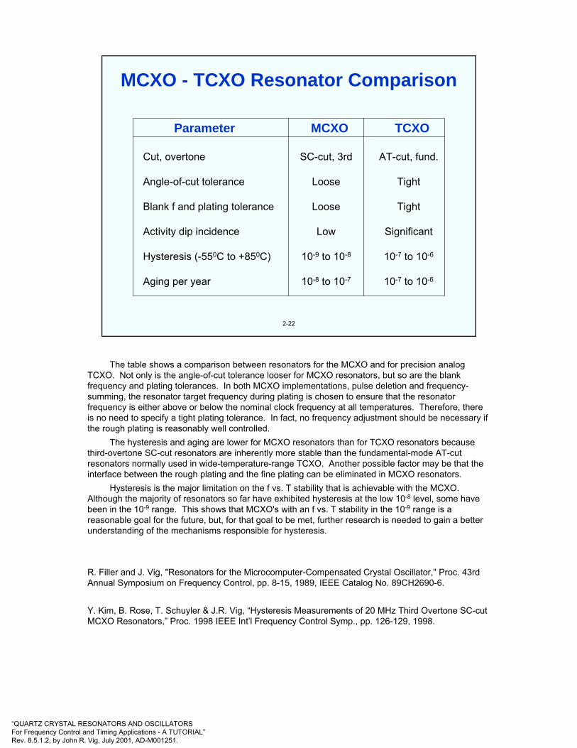
MCXO - TCXO Resonator Comparison
The table shows a comparison between resonators for the MCXO and for precision analog TCXO. Not only is the angle-of-cut tolerance looser for MCXO resonators, but so are the blank frequency and plating tolerances. In both MCXO implementations, pulse deletion and frequency-summing, the resonator target frequency during plating is chosen to ensure that the resonator frequency is either above or below the nominal clock frequency at all temperatures. Therefore, there is no need to specify a tight plating tolerance. In fact, no frequency adjustment should be necessary if the rough plating is reasonably well controlled.
The hysteresis and aging are lower for MCXO resonators than for TCXO resonators because third-overtone SC-cut resonators are inherently more stable than the fundamental-mode AT-cut resonators normally used in wide-temperature-range TCXO. Another possible factor may be that the interface between the rough plating and the fine plating can be eliminated in MCXO resonators.
Hysteresis is the major limitation on the f vs. T stability that is achievable with the MCXO. Although the majority of resonators so far have exhibited hysteresis at the low 10-8 level, some have been in the 10-9 range. This shows that MCXO's with an f vs. T stability in the 10-9 range is a reasonable goal for the future, but, for that goal to be met, further research is needed to gain a better understanding of the mechanisms responsible for hysteresis.
R. Filler and J. Vig, "Resonators for the Microcomputer-Compensated Crystal Oscillator," Proc. 43rd Annual Symposium on Frequency Control, pp. 8-15, 1989, IEEE Catalog No. 89CH2690-6.
Y. Kim, B. Rose, T. Schuyler & J.R. Vig, “Hysteresis Measurements of 20 MHz Third Overtone SC-cut MCXO Resonators,” Proc. 1998 IEEE Int’l Frequency Control Symp., pp. 126-129, 1998.

“QUARTZ CRYSTAL RESONATORS AND OSCILLATORSFor Frequency Control and Timing Applications - A TUTORIAL”Rev. 8.5.1.2, by John R. Vig, July 2001, AD-M001251.
2-23
Optical fiber
Electricaltransmission
line
Bias
Optical out"Pump Laser"
OpticalFiber
Photodetector
RF Amplifier
Filter
RF driving port
Electricalinjection
RF coupler
Electricaloutput
OpticalInjection
Opticalcoupler
Piezoelectric fiber stretcher
Opto-Electronic Oscillator (OEO)
The OEO utilizes the transmission characteristics of a modulator together with a fiber optic delay line to convert light energy into spectrally pure rf/microwave reference signals. The OEO’s schematic diagram is shown above. Light from a laser is introduced into an electrooptical (E/O) modulator, the output of which is passed through a long fiber optic link, and detected with a photodetector. The output of the photodetector is amplified, filtered and fed back to the electrical port of the modulator. This configuration supports self-sustained oscillations at a frequency determined by the fiber delay length, bias setting of the modulator, and the bandpass characteristics of the filter. It also provides for both electrical and optical outputs.
The noise of an OEO has been measured to be -140 dBc/Hz at 10 kHz from a 10 GHz carrier. This is the highest spectral purity demonstrated by an open loop oscillator in this frequency range (as of 1999). How stable an OEO can be with respect to other parameters, such as temperature, acceleration and humidity, is being investigated.
S. Yao and L. Maleki, “New Results with the Opto-electronic Oscillators (OEO),” Proc. 1996 IEEE Int’l Frequency Control Symposium, pp. 1219-1222, 1996.
X. S. Yao and L. Maleki, "Optoelectronic Oscillator for Photonic Systems," IEEE Journal of Quantum Electronics, 32, 1141, 1996.
X. S. Yao, L. Maleki and L. Davis, ”Coupled Opto-electronic Oscillators,” Proc. 1998 IEEE Int’l Frequency Control Symposium, pp. 540-544, 1998.

“QUARTZ CRYSTAL RESONATORS AND OSCILLATORSFor Frequency Control and Timing Applications - A TUTORIAL”Rev. 8.5.1.2, by John R. Vig, July 2001, AD-M001251.
3
CHAPTER 3Quartz Crystal Resonators
General References
A. Ballato, "Piezoelectric Resonators," in B. Parzen, Design of Crystal and Other Harmonic Oscillators, pp. 66-122, John Wiley and Sons, Inc., 1983.
V. E. Bottom, Introduction to Quartz Crystal Unit Design, Van Nostrand Reinhold Company, 1982.
R. A. Heising, Quartz Crystals for Electrical Circuits, D. Van Nostrand Co., 1946.
T. R. Meeker, “Theory and Properties of Piezoelectric Resonators and Waves,” in E. A. Gerber and A. Ballato, Precision Frequency Control, Vol. 1, pp. 48-118, Academic Press, 1985.
J. A. Kusters, "Resonator and Device Technology," in E. A. Gerber and A. Ballato, Precision Frequency Control, Vol. 1, pp. 161-183, Academic Press, 1985.
E. Hafner, "Resonator and Device Measurements," in E. A. Gerber and A. Ballato, Precision Frequency Control, Vol. 2, pp.1-44, Academic Press, 1985.
J. C. Brice, "Crystals for Quartz Resonators," Rev. of Modern Physics, Vol. 57, pp. 105-146, 1985.
J. R. Vig & F. L. Walls, "Fundamental Limits on the Frequency Instabilities of Quartz Crystal Oscillators," Proc. 1994 IEEE Int'l Frequency Control Symposium, pp. 506-523, 1994; also, in IEEE Trans. on Ultrasonics, Ferroelectrics, and Frequency Control, vol. 42, pp. 576-589, July 1995.
J. R. Vig, "Introduction to Quartz Frequency Standards," Army Research Lab. Tech. Rep't SLCET-TR-92-1 (Rev. 1), October 1992, AD-A256373; also in the Tutorials from the Twenty-third Annual Precise Time and Time Interval (PTTI) Applications and Planning Meeting, Pasadena, CA, pp. 1-49, December 1991, AD-A254745, and at <http://www.ieee.org/uffc/fc>.
“QUARTZ CRYSTAL RESONATORS AND OSCILLATORSFor Frequency Control and Timing Applications - A TUTORIAL”Rev. 8.5.1.2, by John R. Vig, July 2001, AD-M001251.
3-1
Quartz is the only material known that possesses the following combination of properties:
• Piezoelectric ("pressure-electric"; piezein = to press, in Greek)
• Zero temperature coefficient cuts exist
• Stress compensated cut exists
• Low loss (i.e., high Q)
• Easy to process; low solubility in everything, under "normal" conditions, except the fluoride and hot alkali etchants; hard but not brittle
• Abundant in nature; easy to grow in large quantities, at low cost, and with relatively high purity and perfection. Of the man-grown single crystals, quartz, at ~3,000 tons per year, is second only to silicon in quantity grown (3 to 4 times as much Si is grown annually, as of 1997).
Why Quartz?
-
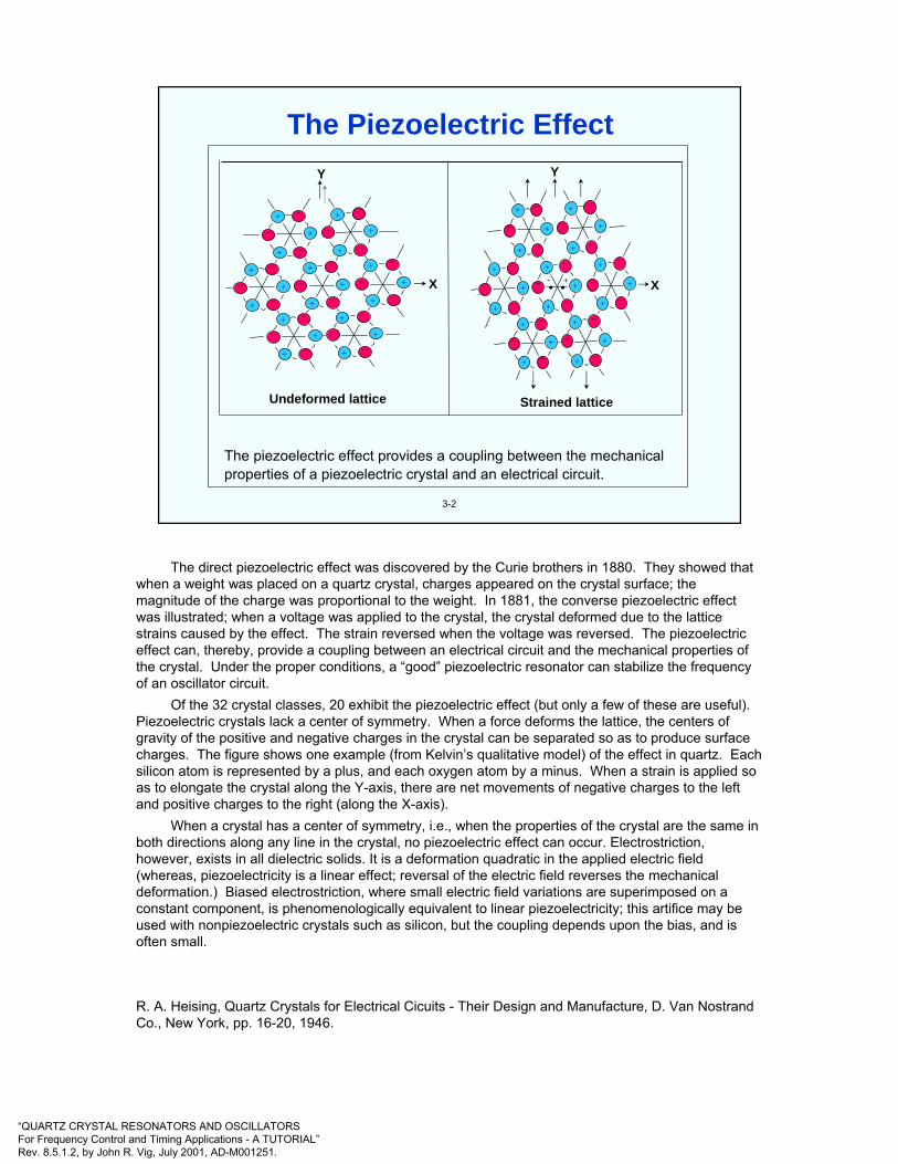
“QUARTZ CRYSTAL RESONATORS AND OSCILLATORSFor Frequency Control and Timing Applications - A TUTORIAL”Rev. 8.5.1.2, by John R. Vig, July 2001, AD-M001251.
3-2
The piezoelectric effect provides a coupling between the mechanical properties of a piezoelectric crystal and an electrical circuit.
Undeformed lattice
X
+
+
+
+
+
+
+
+
+
+
+
+
+
+
+
+
+
+
+
++
__
_
_ _
_ _
_
_
_
_
_ _
_
_
_
_
_
_
_
Strained lattice
+
+
+
+
+
+
+
+
+
+
+
+
+
+
+
+
+
+
+
++
__
_
_ _
_ _
_
_
___
_ _
_
_
_
_
_
_
_
X• •- +
YY
_ _
The Piezoelectric Effect
The direct piezoelectric effect was discovered by the Curie brothers in 1880. They showed that when a weight was placed on a quartz crystal, charges appeared on the crystal surface; the magnitude of the charge was proportional to the weight. In 1881, the converse piezoelectric effect was illustrated; when a voltage was applied to the crystal, the crystal deformed due to the lattice strains caused by the effect. The strain reversed when the voltage was reversed. The piezoelectric effect can, thereby, provide a coupling between an electrical circuit and the mechanical properties of the crystal. Under the proper conditions, a “good” piezoelectric resonator can stabilize the frequency of an oscillator circuit.
Of the 32 crystal classes, 20 exhibit the piezoelectric effect (but only a few of these are useful). Piezoelectric crystals lack a center of symmetry. When a force deforms the lattice, the centers of gravity of the positive and negative charges in the crystal can be separated so as to produce surface charges. The figure shows one example (from Kelvin’s qualitative model) of the effect in quartz. Each silicon atom is represented by a plus, and each oxygen atom by a minus. When a strain is applied so as to elongate the crystal along the Y-axis, there are net movements of negative charges to the left and positive charges to the right (along the X-axis).
When a crystal has a center of symmetry, i.e., when the properties of the crystal are the same in both directions along any line in the crystal, no piezoelectric effect can occur. Electrostriction, however, exists in all dielectric solids. It is a deformation quadratic in the applied electric field (whereas, piezoelectricity is a linear effect; reversal of the electric field reverses the mechanical deformation.) Biased electrostriction, where small electric field variations are superimposed on a constant component, is phenomenologically equivalent to linear piezoelectricity; this artifice may be used with nonpiezoelectric crystals such as silicon, but the coupling depends upon the bias, and is often small.
R. A. Heising, Quartz Crystals for Electrical Cicuits - Their Design and Manufacture, D. Van NostrandCo., New York, pp. 16-20, 1946.

“QUARTZ CRYSTAL RESONATORS AND OSCILLATORSFor Frequency Control and Timing Applications - A TUTORIAL”Rev. 8.5.1.2, by John R. Vig, July 2001, AD-M001251.
3-3
In quartz, the five strain components shown may be generated by an electric field.The modes shown on the next page may be excited by suitably placed and shaped electrodes. The shear strain about the Z-axis produced by the Y-component of thefield is used in the rotated Y-cut family, including the AT, BT, and ST-cuts.
STRAIN
EXTENSIONALalong:
SHEARabout:
FIELD along:
X
Y
Z
X
Y
Z
X Y Z
√√
√√√
X
Y
Z
The Piezoelectric Effect in Quartz
Piezoelectricity is a linear effect. Reversal of the electric field reverses the strain, i.e., the mechanical deformation.
The electromechanical (also called piezoelectric) coupling factor k is an important characteristic of a piezoelectric material; k is between zero and one and is dimensionless, e.g., k = 8.8% for AT-cut quartz, and k = 4.99% for SC-cut quartz. It is a measure of the efficacy of piezoelectric transduction, and it is a determinant of important device characteristics such as filter bandwidth, insertion loss, and the location and spacings of resonators' critical frequencies (e.g., the series resonance to antiresonance frequency spacing).
----------------------------W. G. Cady, Piezoelectricity, Dover Publications, Inc., New York, 1964.
A. Ballato, Piezoelectricity: Venerable Effects, Modern Thrusts, Army Research Laboratory Technical Report ARL-TR-70, August 1994. Available from NTIS, and among the “Review Papers” at www.ieee-uffc.org/fc
G. S. Kino, Acoustic Waves: Devices, Imaging, and Analog Signal Processing, Prentice-Hall, Inc., 1964. This book is available on-line to IEEE UFFC-S members at www.ieee-uffc.org/archive
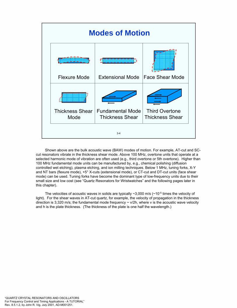
“QUARTZ CRYSTAL RESONATORS AND OSCILLATORSFor Frequency Control and Timing Applications - A TUTORIAL”Rev. 8.5.1.2, by John R. Vig, July 2001, AD-M001251.
3-4
Flexure Mode Extensional Mode Face Shear Mode
Thickness Shear Mode
Fundamental ModeThickness Shear
Third OvertoneThickness Shear
Modes of Motion
Shown above are the bulk acoustic wave (BAW) modes of motion. For example, AT-cut and SC-cut resonators vibrate in the thickness shear mode. Above 100 MHz, overtone units that operate at a selected harmonic mode of vibration are often used (e.g., third overtone or 5th overtone). Higher than 100 MHz fundamental mode units can be manufactured by, e.g., chemical polishing (diffusion controlled wet etching), plasma etching, and ion milling techniques. Below 1 MHz, tuning forks, X-Y and NT bars (flexure mode), +5° X-cuts (extensional mode), or CT-cut and DT-cut units (face shear mode) can be used. Tuning forks have become the dominant type of low-frequency units due to their small size and low cost (see “Quartz Resonators for Wristwatches” and the following pages later in this chapter).
The velocities of acoustic waves in solids are typically ~3,000 m/s (~10-5 times the velocity of light). For the shear waves in AT-cut quartz, for example, the velocity of propagation in the thickness direction is 3,320 m/s; the fundamental mode frequency ~ v/2h, where v is the acoustic wave velocity and h is the plate thickness. (The thickness of the plate is one half the wavelength.)
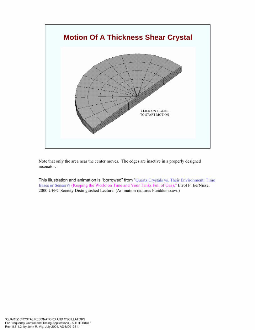
“QUARTZ CRYSTAL RESONATORS AND OSCILLATORSFor Frequency Control and Timing Applications - A TUTORIAL”Rev. 8.5.1.2, by John R. Vig, July 2001, AD-M001251.
Motion Of A Thickness Shear Crystal
CLICK ON FIGURETO START MOTION
Note that only the area near the center moves. The edges are inactive in a properly designed resonator.
This illustration and animation is “borrowed” from “Quartz Crystals vs. Their Environment: Time Bases or Sensors? (Keeping the World on Time and Your Tanks Full of Gas),” Errol P. EerNisse, 2000 UFFC Society Distinguished Lecture. (Animation requires Funddemo.avi.)

“QUARTZ CRYSTAL RESONATORS AND OSCILLATORSFor Frequency Control and Timing Applications - A TUTORIAL”Rev. 8.5.1.2, by John R. Vig, July 2001, AD-M001251.
3-5
Metallicelectrodes
Resonatorplate substrate
(the “blank”)
u
Conventional resonator geometryand amplitude distribution, u
Resonator Vibration Amplitude Distribution
In an ideal resonator, the amplitude of vibration falls off approximately exponentially outside the electrodes. In a properly designed resonator, a negligible amount of energy is lost to the mounting and bonding structure, i.e., the edges must be inactive in order for the resonator to be able to possess a high Q. The displacement of a point on the resonator surface is proportional to the drive current. At the typical drive currents used in (e.g., 10 MHz) thickness shear resonators, the peak displacement is a few atomic spacings.
The peak acceleration of a point on the surface is often more than a million ‘g’s. To show this, if the displacement u = uo sin ωt, then, the acceleration = d2u/dt2 = - ω2 uo sin ωt, and the peak acceleration = - ω2 uo. If we assume that uo = two lattice spacings ~1 x 10⁻⁹ m, then, at 10 MHz, ω2 uo = (2π x 107)2 (10-9) ~ 106 g.
B. Capelle, J. Detaint, A. Zarka, Y. Zheng and J. Schwartzel, “Mode Shape Analysis Techniques Using Synchrotron X-ray Topography,” Proc. 44th Ann. Symp. On Frequency Control, pp. 416-423, 1990.
J. S. Yang and H. F. Tiersten, “An Analysis of Contoured Quartz Resonators with Beveled Cylindrical Edges,” Proc. 1995 Int’l Frequency Control Symp., pp. 727-739, 1995.
H. F. Tiersten and D. S. Stevens, “The Evaluationof the Coefficients of Nonlinear Resonance for SC-cut Quartz Resonators,” Proc. 39th Annual Symposium on Frequency Control, pp. 325-332, 1985, IEEE Catalog No. 85CH2186-5.
V. E. Bottom, Introduction to Quartz Crystal Unit Design, Van Nostrand Reinhold Company, 1982.

“QUARTZ CRYSTAL RESONATORS AND OSCILLATORSFor Frequency Control and Timing Applications - A TUTORIAL”Rev. 8.5.1.2, by John R. Vig, July 2001, AD-M001251.
3-6
X-ray topographs (21•0 plane) of various modes excited during a frequencyscan of a fundamental mode, circular, AT-cut resonator. The first peak, at3.2 MHz, is the main mode; all others are unwanted modes. Dark areascorrespond to high amplitudes of displacement.
3200 3400 3600 3800
0 db.
-10 db.
-20
-30 db.
-40 db.
Frequency, in kHz
Res
pons
e 3200
MH
Z
3256
3383
3507
3555
3642
3652
3707
3742
3802
3852
Resonant Vibrations of a Quartz Plate
Resonators of finite dimensions have complicated mode specra. “Unwanted” modes occur above the main resonance, as is shown above. These unwanted (also called “spurious”) modes are especially troublesome in filter applications. In oscillator applications, controlling the unwanted modes is not as critical because, as long as the unwanted modes are at least 10 dB below the main mode, the oscillation will be at the main mode. Contouring, and “energy trapping” rules are used to minimize the unwanted modes. The energy trapping rules consist of certain relationships between the electrode and plate dimensions.
As Shockley, et. al pointed out, “energy trapping” and the concepts of “cutoff frequency” and exponentially decaying waves in piezoelectric resonators are similar to the well-know such phenomena in microwave and optical cavities (related to total internal reflection).
Mindlin has been quoted as having said about spurious modes “they aren’t spurious; they are supposed to be there…the theory predicts them!”-------------------------
K. Haruta and W. J. Spencer, "X-ray Diffraction Study of Vibrational Modes," Proc. 20th Annual Symposium on Frequency Control, pp. 1-13, April 1966, AD-800523. Copies available from National Technical Information Service.
W. J. Spencer, "Observation of Resonant Vibrations and Defect Structure in Single Crystals by X-ray Diffraction Topography," in Physical Acoustics, Vol. V, W. P. Mason and R. N. Thurston, Eds., Academic Press, New York, 1968.
B. Capelle, J. Detaint, A. Zarka, Y. Zheng and J. Schwartzel, “Mode Shape Analysis Techniques Using Synchrotron X-ray Topography,” Proc. 44th Ann. Symp. On Frequency Control, pp. 416-423, 1990.
W. Shockley, D. R. Curran & D. J. Koneval, “Energy Trapping and Related Studies of Multiple Electrode Filter Crystals,” Proc. 17th Ann. Symp. On Frequency Control, pp. 88-124, 1963.
W. Shockley, D. R. Curran & D. J. Koneval, “Trapped Energy Modes in Quartz Crystal Filters,” J. Acoustical Soc. Amer., vol. 41, pp. 981-993, 1967.

“QUARTZ CRYSTAL RESONATORS AND OSCILLATORSFor Frequency Control and Timing Applications - A TUTORIAL”Rev. 8.5.1.2, by John R. Vig, July 2001, AD-M001251.
0
jX
-jX
Rea
ctan
ce
Fundamental mode3rd overtone
5th overtone
Frequency
Spuriousresponses Spurious
responses
3-7
Spuriousresponses
Overtone Response of a Quartz Crystal
The above figure illustrates the mode spectrum of a quartz resonator, showing the fundamental mode, third overtone, fifth overtone, and some of the spurious responses (“spurs”), i.e., unwanted modes. In oscillator applications, the oscillator usually selects the strongest mode. Some of the unwanted modes have steep frequency vs. temperature characteristics. Occasionally, as the temperature changes, at a certain temperature, the frequency of an unwanted mode coincides with the oscillator frequency, which causes an “activity dip” (see next page, and “Activity Dips” in chapter 4). At the activity dip, excitation of the unwanted mode results in extra energy dissipation in the resonator, which results in a decrease in the Q, an increase in the equivalent series resistance, and a change in the frequency of the oscillator. When the resistance increase is sufficiently large, the oscillation stops, i.e., the oscillator fails. When the temperature changes away from the activity dip temperature, the oscillation restarts.
Unwanted modes can be controlled by proper design and fabrication methods. Maintaining the correct relationships among electrode and resonator plate dimensions (i.e., applying energy trapping rules), and maintaining the parallelism between the major faces of the resonator plate, can minimize the unwanted modes.
W. Shockley, D. R. Curran & D. J. Koneval, “Trapped Energy Modes in Quartz Crystal Filters,” J. Acoustical Soc. Amer., vol. 41, pp. 981-993, 1967.
G.K. Guttwein, T. J. Lukaszek, and A. D. Ballato, “Practical Consequences of Modal Parameter Control in Crystal Resonators,” Proc. 21st Ann. Symp. On frequency Control, pp. 115-137, 1967.
T. R. Meeker, “Theory and Properties of Piezoelectric Resonators and Waves,” in E. A. Gerber and A. Ballato, Precision Frequency Control, Vol. 1, pp. 48-118, Academic Press, 1985.
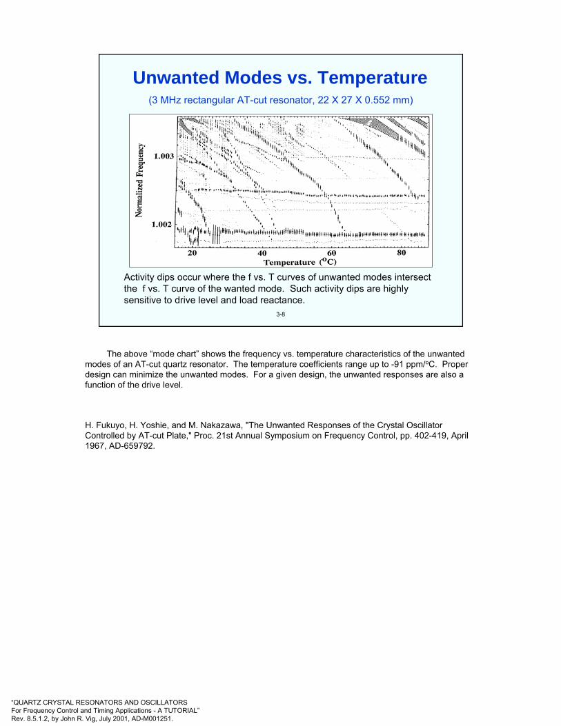
“QUARTZ CRYSTAL RESONATORS AND OSCILLATORSFor Frequency Control and Timing Applications - A TUTORIAL”Rev. 8.5.1.2, by John R. Vig, July 2001, AD-M001251.
3-8
(3 MHz rectangular AT-cut resonator, 22 X 27 X 0.552 mm)
Activity dips occur where the f vs. T curves of unwanted modes intersect the f vs. T curve of the wanted mode. Such activity dips are highly sensitive to drive level and load reactance.
Unwanted Modes vs. Temperature
The above “mode chart” shows the frequency vs. temperature characteristics of the unwanted modes of an AT-cut quartz resonator. The temperature coefficients range up to -91 ppm/oC. Proper design can minimize the unwanted modes. For a given design, the unwanted responses are also a function of the drive level.
H. Fukuyo, H. Yoshie, and M. Nakazawa, "The Unwanted Responses of the Crystal Oscillator Controlled by AT-cut Plate," Proc. 21st Annual Symposium on Frequency Control, pp. 402-419, April 1967, AD-659792.

“QUARTZ CRYSTAL RESONATORS AND OSCILLATORSFor Frequency Control and Timing Applications - A TUTORIAL”Rev. 8.5.1.2, by John R. Vig, July 2001, AD-M001251.
3-9
• In piezoelectric materials, electrical current and voltage are coupled to elastic displacement and stress:
T = [c] S - [e] ED = [e] S + [∈] E
where T = stress tensor, [c] = elastic stiffness matrix, S = strain tensor, [e] = piezoelectric matrixE = electric field vector, D = electric displacement vector, and [∈] = is the dielectric matrix
• For a linear piezoelectric materialc11 c12 c13 c14 c15 c16 −e11 −e21 −e31c21 c22 c23 c24 c25 c26 −e12 −e22 −e32c31 c32 c33 c34 c35 c36 −e13 −e23 −e33c41 c42 c43 c44 c45 c46 −e14 −e24 −e34
c51 c52 c53 c54 c55 c56 −e15 −e25 −e35c61 c62 c63 c64 c65 c66 −e16 −e26 −e36e11 e12 e13 e14 e15 e16 ∈11 ∈12 ∈13e21 e22 e23 e24 e25 e26 ∈21 ∈22 ∈23e31 e32 e33 e34 e35 e36 ∈31 ∈32 ∈33
T1T2T3T4T5T6D1D2D3
=
whereT1 = T11 S1 = S11T2 = T22 S2 = S22T3 = T33 S3 = S33T4 = T23 S4 = 2S23T5 = T13 S5 = 2S13T6 = T12 S6 = 2S12
S1S2S3S4S5S6E1E2E3
• Elasto-electric matrix for quartzS1 S2 S3 S4 S5 S6 -E1 -E2 -E3
etT1
T2
T3
T4
T5
T6
D1
D2
D3 e
CEX
S622
10LINES JOIN NUMERICAL EQUALITIESEXCEPT FOR COMPLETE RECIPROCITYACROSS PRINCIPAL DIAGONAL
INDICATES NEGATIVE OF INDICATES TWICE THE NUMERICAL
EQUALITIESINDICATES 1/2 (c11 - c12)X
∈
Mathematical Description of a Quartz Resonator
cij in the matrix on the left ≡ cc in the box at the right, and ∈ ij in the matrix ≡ ∈ s at the right
-----------------T. R. Meeker, “Theory and Properties of Piezoelectric Resonators and Waves,” in E. A. Gerber and A. Ballato, Precision Frequency Control, Vol. 1, pp. 48-118, Academic Press, 1985.ANSI/IEEE Std 176-1987 IEEE Standard on PiezoelectricityA. Ballato, “Piezoelectricity: Old Effect, New Thrusts,” IEEE Trans. UFFC, v.42, pp. 916-926, Sept. 1995

“QUARTZ CRYSTAL RESONATORS AND OSCILLATORSFor Frequency Control and Timing Applications - A TUTORIAL”Rev. 8.5.1.2, by John R. Vig, July 2001, AD-M001251.
3-10
• Number of independent non-zero constants depend on crystal symmetry. For quartz (trigonal, class 32), there are 10 independent linear constants - 6 elastic, 2 piezoelectric and 2 dielectric. "Constants” depend on temperature, stress, coordinate system, etc.
• To describe the behavior of a resonator, the differential equations for Newton's law of motion for acontinuum, and for Maxwell's equation* must be solved, with the proper electrical and mechanical boundary conditions at the plate surfaces.
• Equations are very "messy" - they have never been solved in closed form for physically realizable three-dimensional resonators. Nearly all theoretical work has used approximations.
• Some of the most important resonator phenomena (e.g., acceleration sensitivity) are due to nonlineareffects. Quartz has numerous higher order constants, e.g., 14 third-order and 23 fourth-order elastic constants, as well as 16 third-order piezoelectric coefficients are known; nonlinear equations are extremelymessy.
* Magnetic field effects are generally negligible; quartz is diamagnetic, however, magnetic fields can affect the mounting structure and electrodes.
,0xD0D ;uρ
xT ma (F
i
ii
j
ij=
∂∂
⇒=⋅∇=∂∂
⇒=
). ; etcxu
xuS ; )
i
j
j
i(21
xE
iji
i ∂∂
∂∂
+=∂∂
−=φ
Mathematical Description - Continued
-

“QUARTZ CRYSTAL RESONATORS AND OSCILLATORSFor Frequency Control and Timing Applications - A TUTORIAL”Rev. 8.5.1.2, by John R. Vig, July 2001, AD-M001251.
3-11
Where fn = resonant frequency of n-th harmonich = plate thicknessρ = densitycij = elastic modulus associated with the elastic wave
being propagated
where Tf is the linear temperature coefficient of frequency. The temperature coefficient of cij is negative for most materials (i.e., “springs” become “softer”as T increases). The coefficients for quartz can be +, - or zero (see next page).
5...3,1,n,ρc
2hnf ij
n ==
( )dTdc
2c1
dTd
21
dTdh
h1
dTdf
f1
dTflogdT ij
ij
n
n
nf +
ρρ
−−
===
Infinite Plate Thickness Shear Resonator
The velocity of propagation, v, of a wave in the thickness direction of a thin plate, and the resonant frequency, fn, of an infinite plate vibrating in a thickness mode are
v=√(cij/ρ), and fn = n/2h√(cij/ρ)respectively, where cij is the elastic stiffness associated with the wave being propagated, ρ is the density of the plate, and 2h is the thickness. The frequency can also be expressed (taking the logarithm of both sides) as
log fn = log(n/2) - log h + 1/2 (log cij - log ρ)Differentiating this equation gives the above expression for Tf.
Quartz expands when heated; dh/dT is positive along all directions, and dρ/dT is negative (see “Thermal Expansion Coefficients of Quartz” in chapter 4). The temperature coefficient of cij also varies with direction. It is fortunate that, in quartz, directions exist such that the temperature coefficient of cijbalances out the effects of the thermal expansion coefficients, i.e., zero temperature coefficient cuts exist in quartz.
V. E. Bottom, Introduction to Quartz Crystal Unit Design, Van Nostrand Reinhold Company, 1982.

“QUARTZ CRYSTAL RESONATORS AND OSCILLATORSFor Frequency Control and Timing Applications - A TUTORIAL”Rev. 8.5.1.2, by John R. Vig, July 2001, AD-M001251.
3-12
The properties of quartz vary greatly with crystallographic direction. For example, when a quartz sphere is etched deeply in HF, thesphere takes on a triangular shape when viewed along the Z-axis, anda lenticular shape when viewed along the Y-axis. The etching rate ismore than 100 times faster along the fastest etching rate direction (theZ-direction) than along the slowest direction (the slow-X-direction).
The thermal expansion coefficient is 7.8 x 10⁻⁶/°C along the Z-direction, and 14.3 x 10⁻⁶/°C perpendicular to the Z-direction; the temperature coefficient of density is, therefore, -36.4 x 10⁻⁶/°C.
The temperature coefficients of the elastic constants range from-3300 x 10-6/°C (for C12) to +164 x 10-6/°C (for C66).
For the proper angles of cut, the sum of the first two terms in Tf on theprevious page is cancelled by the third term, i.e., temperature compensated cuts exist in quartz. (See next page.)
Quartz is Highly Anisotropic
See chapter 5, especially “Deeply Dissolved Quartz Sphere,” for additional information about quartz and its anisotropy.
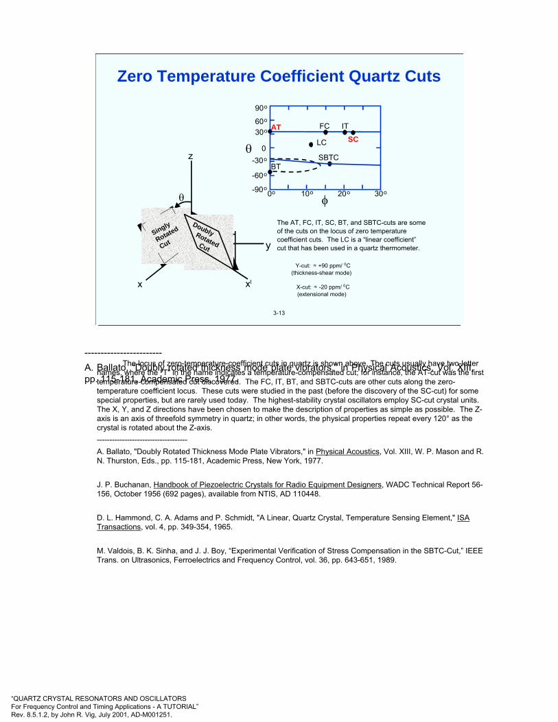
“QUARTZ CRYSTAL RESONATORS AND OSCILLATORSFor Frequency Control and Timing Applications - A TUTORIAL”Rev. 8.5.1.2, by John R. Vig, July 2001, AD-M001251.
3-13
x xl
y
φ
z
θ
θ
The AT, FC, IT, SC, BT, and SBTC-cuts are some of the cuts on the locus of zero temperature coefficient cuts. The LC is a “linear coefficient”cut that has been used in a quartz thermometer.
Y-cut: ≈ +90 ppm/0C(thickness-shear mode)
X-cut: ≈ -20 ppm/0C(extensional mode)
90o
60o
30o
0-30o
-60o
-90o0o 10o 20o 30o
AT FC IT
LC SC
SBTCBT
θ
φ
Singly
Rotated
Cut
DoublyRotatedCut
Zero Temperature Coefficient Quartz CutsZero Temperature Coefficient Quartz Cuts
3-13
x xl
yφ
z
θ
θ
The AT, FC, IT, SC, BT, and SBTC-cuts are someof the cuts on the locus of zero temperaturecoefficient cuts. The LC is a “linear coefficient”cut that has been used in a quartz thermometer.
Y-cut: ≈ +90 ppm/ 0C(thickness-shear mode)
X-cut: ≈ -20 ppm/ 0C(extensional mode)
90o
60o
30o
0-30o
-60o
-90o0o 10o 20o 30o
AT FC IT
LC SC
SBTCBT
θ
φ
Singly
Rotated
Cut
DoublyRotatedCut
The locus of zero-temperature-coefficient cuts in quartz is shown above. The cuts usually have two-letter names, where the "T" in the name indicates a temperature-compensated cut; for instance, the AT-cut was the first temperature-compensated cut discovered. The FC, IT, BT, and SBTC-cuts are other cuts along the zero-temperature coefficient locus. These cuts were studied in the past (before the discovery of the SC-cut) for some special properties, but are rarely used today. The highest-stability crystal oscillators employ SC-cut crystal units. The X, Y, and Z directions have been chosen to make the description of properties as simple as possible. The Z-axis is an axis of threefold symmetry in quartz; in other words, the physical properties repeat every 120° as the crystal is rotated about the Z-axis. ------------------------------------A. Ballato, "Doubly Rotated Thickness Mode Plate Vibrators," in Physical Acoustics, Vol. XIII, W. P. Mason and R. N. Thurston, Eds., pp. 115-181, Academic Press, New York, 1977.
J. P. Buchanan, Handbook of Piezoelectric Crystals for Radio Equipment Designers, WADC Technical Report 56-156, October 1956 (692 pages), available from NTIS, AD 110448.
D. L. Hammond, C. A. Adams and P. Schmidt, "A Linear, Quartz Crystal, Temperature Sensing Element," ISA Transactions, vol. 4, pp. 349-354, 1965.
M. Valdois, B. K. Sinha, and J. J. Boy, “Experimental Verification of Stress Compensation in the SBTC-Cut,” IEEE Trans. on Ultrasonics, Ferroelectrics and Frequency Control, vol. 36, pp. 643-651, 1989.
------------------------A. Ballato, “Doubly rotated thickness mode plate vibrators,” in Physical Acoustics, Vol. XIII, pp. 115-181, Academic Press, 1977.

“QUARTZ CRYSTAL RESONATORS AND OSCILLATORSFor Frequency Control and Timing Applications - A TUTORIAL”Rev. 8.5.1.2, by John R. Vig, July 2001, AD-M001251.
3-14
• Advantages of the SC-cut • Thermal transient compensated (allows faster warmup OCXO) • Static and dynamic f vs. T allow higher stability OCXO and MCXO• Better f vs. T repeatability allows higher stability OCXO and MCXO• Far fewer activity dips • Lower drive level sensitivity • Planar stress compensated; lower ∆f due to edge forces and bending • Lower sensitivity to radiation • Higher capacitance ratio (less ∆f for oscillator reactance changes) • Higher Q for fundamental mode resonators of similar geometry • Less sensitive to plate geometry - can use wide range of contours
• Disadvantage of the SC-cut : More difficult to manufacture for OCXO (but iseasier to manufacture for MCXO than is an AT-cut for precision TCXO)
• Other Significant Differences• B-mode is excited in the SC-cut, although not necessarily in LFR's • The SC-cut is sensitive to electric fields (which can be used for
compensation)
Comparison of SC and AT-cuts
See the next chapter for specific comparisons between AT-cut and SC-cut resonators, e.g., see “Warmup of AT- and SC-cut Resonators”.
A. Ballato, "Doubly Rotated Thickness Mode Plate Vibrators," Physical Acoustics, Vol. XIII, pp. 115-181, Academic Press, Inc., 1977.
J. A. Kusters, "The SC Cut Crystal - An Overview," Proc. IEEE Ultrasonics Symposium, pp. 402-409, 1981.

“QUARTZ CRYSTAL RESONATORS AND OSCILLATORSFor Frequency Control and Timing Applications - A TUTORIAL”Rev. 8.5.1.2, by John R. Vig, July 2001, AD-M001251.
Atte
nuat
ion
Normalized Frequency (referenced to the fundamental c-mode)
0
-20
-10
-30
-400 1 2 3 4 5 6
1.0
1.10
1.88
3.0
3.30
5.0
5.505.65
c(1) b(1) a(1) c(3) b(3) c(5) b(5) a(3)
3-15
a-mode: quasi-longitudinal modeb-mode: fast quasi-shear modec-mode: slow quasi-shear mode
Mode Spectrograph of an SC-cut
In the above mode spectrograph of an SC-cut resonator, the Nth overtone of mode m is labeled m(N) (after Ballato). The frequency of each resonance is normalized to that of the fundamental c-mode. The modal attenuations vary with resonator design. In the above example, the b-modes’strengths are greater than the c-modes’ (which is often the case). Therefore, the oscillator must include mode selection circuitry in order to insure that the oscillator operates on the desired c-mode.
A. Ballato, "Piezoelectric Resonators," in B. Parzen, Design of Crystal and Other Harmonic Oscillators, pp. 66-122, John Wiley and Sons, Inc., 1983.
J. A. Kusters, M. C. Fischer, J. G. Leach, "Dual mode operation of temperature and stress compensated crystals," Proc. of the 32nd Annual Frequency Control Symposium, 1978. pp. 389-397.
R. Bourquin, J.J. Boy, B. Dulmet, “SC-cut Resonator With Reduction of b-mode Electrical Response,”Proc. 1997 IEEE Int’l Frequency Control Symposium, pp. 704-709.

“QUARTZ CRYSTAL RESONATORS AND OSCILLATORSFor Frequency Control and Timing Applications - A TUTORIAL”Rev. 8.5.1.2, by John R. Vig, July 2001, AD-M001251.
400
200
0
-200
-400
-600
-800
-1000
-1200
0 10 20
30 40 50 60 70
b-Mode (Fast Shear)-25.5 ppm/oC
c-Mode (Slow Shear)
Temperature (OC)FR
EQU
ENC
Y D
EVIA
TIO
N (P
PM)
3-16
SC- cut f vs. T for b-mode and c-mode
Shown above are frequency vs. temperature characteristics of the b-mode and c-mode of a 10 MHz 3rd overtone SC-cut resonator. The b-mode’s f vs. T is monotonic, with a slope of about -25.5 ppm per degree C. The c-mode is temperature compensated; its exact f vs. T characteristic depends on the angles of cut, overtone, contour, etc. The b-mode’s frequency is about 9.4% higher than the c-mode’s (but it can range from ~9% to 10%, depending on design).
Both modes can be excited simultaneously, without the modes interfering with each other. The b-mode frequency can be used to instantaneously indicate the temperature of the resonator’s active volume. Dual mode excitation of the b-mode and c-mode frequencies has been used for temperature compensation. In later work, however, dual mode excitation of the fundamental and third overtone c-modes was shown to be superior - see “Resonator Self-temperature Sensing” and subsequent pages in Chapter 2.
J. A. Kusters, M. C. Fischer, J. G. Leach, "Dual mode operation of temperature and stress compensated crystals," Proc. of the 32nd Annual Frequency Control Symposium, 1978. pp. 389-397.

“QUARTZ CRYSTAL RESONATORS AND OSCILLATORSFor Frequency Control and Timing Applications - A TUTORIAL”Rev. 8.5.1.2, by John R. Vig, July 2001, AD-M001251.
B and C Modes Of A Thickness Shear Crystal
C MODE B MODE
CLICK ON FIGURESTO START MOTION
3-17
Note that the c-mode and b-mode displacements are orthogonal.
This illustration and animation is “borrowed” from “Quartz Crystals vs. Their Environment: Time Bases or Sensors? (Keeping the World on Time and Your Tanks Full of Gas),” Errol P. EerNisse, 2000 UFFC Society Distinguished Lecture. (Animations require Discbfull.avi and diskcmode.avi.)
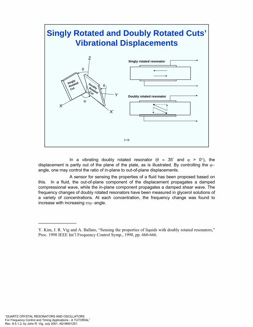
“QUARTZ CRYSTAL RESONATORS AND OSCILLATORSFor Frequency Control and Timing Applications - A TUTORIAL”Rev. 8.5.1.2, by John R. Vig, July 2001, AD-M001251.
Singly
Rotated
CutDoublyRotatedCut
XX’
Y
θ
θ
ϕ
Z
3-18
Singly Rotated and Doubly Rotated Cuts’Vibrational Displacements
Singly rotated resonator
Doubly rotated resonator
In a vibrating doubly rotated resonator (θ ≈ 35° and ϕ > 0°), the displacement is partly out of the plane of the plate, as is illustrated. By controlling the ϕ−angle, one may control the ratio of in-plane to out-of-plane displacements.
A sensor for sensing the properties of a fluid has been proposed based on this. In a fluid, the out-of-plane component of the displacement propagates a damped compressional wave, while the in-plane component propagates a damped shear wave. The frequency changes of doubly rotated resonators have been measured in glycerol solutions of a variety of concentrations. At each concentration, the frequency change was found to increase with increasing πηι−angle.
--------------------------Y. Kim, J. R. Vig and A. Ballato, “Sensing the properties of liquids with doubly rotated resonators,”Proc. 1998 IEEE Int’l Frequency Control Symp., 1998, pp. 660-666.
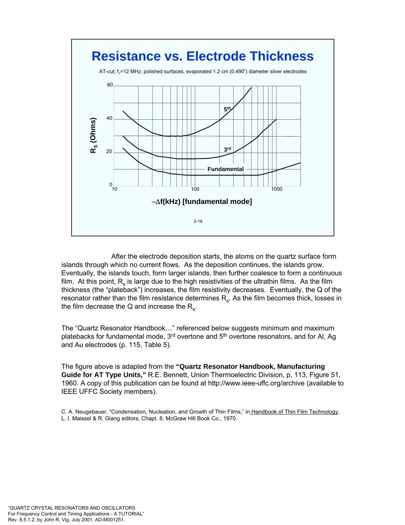
“QUARTZ CRYSTAL RESONATORS AND OSCILLATORSFor Frequency Control and Timing Applications - A TUTORIAL”Rev. 8.5.1.2, by John R. Vig, July 2001, AD-M001251.
RS
(Ohm
s)
−∆f(kHz) [fundamental mode]
0
20
40
60
100 100010
AT-cut; f1=12 MHz; polished surfaces; evaporated 1.2 cm (0.490”) diameter silver electrodes
5th
3rd
Fundamental
3-19
Resistance vs. Electrode Thickness
After the electrode deposition starts, the atoms on the quartz surface form islands through which no current flows. As the deposition continues, the islands grow. Eventually, the islands touch, form larger islands, then further coalesce to form a continuous film. At this point, Rs is large due to the high resistivities of the ultrathin films. As the film thickness (the “plateback”) increases, the film resistivity decreases. Eventually, the Q of the resonator rather than the film resistance determines Rs. As the film becomes thick, losses in the film decrease the Q and increase the Rs.
The “Quartz Resonator Handbook…” referenced below suggests minimum and maximum platebacks for fundamental mode, 3rd overtone and 5th overtone resonators, and for Al, Ag and Au electrodes (p. 115, Table 5).
The figure above is adapted from the “Quartz Resonator Handbook, Manufacturing Guide for AT Type Units,” R.E. Bennett, Union Thermoelectric Division, p, 113, Figure 51,1960. A copy of this publication can be found at http://www.ieee-uffc.org/archive (available to IEEE UFFC Society members).
C. A. Neugebauer, “Condensation, Nucleation, and Growth of Thin Films,“ in Handbook of Thin Film Technology, L. I. Maissel & R. Glang editors, Chapt. 8, McGraw Hill Book Co., 1970.

“QUARTZ CRYSTAL RESONATORS AND OSCILLATORSFor Frequency Control and Timing Applications - A TUTORIAL”Rev. 8.5.1.2, by John R. Vig, July 2001, AD-M001251.
3-20
Base
Mountingclips
Bondingarea
ElectrodesQuartzblank
Cover
Seal
Pins
Quartzblank
Bondingarea
CoverMounting
clips
Seal BasePins
Two-point Mount Package Three- and Four-point Mount Package
Top view of cover
Resonator Packaging
The above illustration shows the typical packages used for AT-cut and SC-cut resonators. Such packages are available in both metal and glass constructions. Other package types include surface mount, ceramic and metal flatpacks, and the cylindrical metal packages used for tuning fork resonators - see “Watch Crystal” later in this chapter.
J. A. Kusters, “Resonator and Device Technology," in E. A. Gerber and A. Ballato, Precision Frequency Control, Vol. 1, pp.161-183, Academic Press, 1985.

“QUARTZ CRYSTAL RESONATORS AND OSCILLATORSFor Frequency Control and Timing Applications - A TUTORIAL”Rev. 8.5.1.2, by John R. Vig, July 2001, AD-M001251.
3-21
C
L
R
Spring
Mass
Dashpot
Equivalent Circuits
The mechanically vibrating system and the circuit shown above are "equivalent," because each can be described by the same differential equation. The mass, spring and damping element (i.e., the dashpot) correspond to the inductor, capacitor and resistor. The driving force corresponds to the voltage, the displacement of the mass to the charge on the capacitor, and the velocity to the current.
A crystal resonator is a mechanically vibrating system that is linked, via the piezoelectric effect, to the electrical world. In the (simplified) equivalent circuit (of one mode of vibration) of a resonator, on the next page, C0 is called the “shunt” capacitance. It is the capacitance due to the electrodes on the crystal plate (plus the stray capacitances due to the crystal enclosure). The R1, L1, C1 portion of the circuit is the "motional arm" which arises from the mechanical vibrations of the crystal. The C0 to C1 ratio is a measure of the interconversion between electrical and mechanical energy stored in the crystal, i.e., of the piezoelectric coupling factor, k, and C1 is a measure of the crystal's "stiffness," i.e., its tunability - see the equation under the equivalent circuit on the next page. When a dc voltage is applied to the electrodes of a resonator, the C0/C1 is also a measure of the ratio of electrical energy stored in the capacitor formed by the electrodes to the energy stored elastically in the crystal due to the lattice strains produced by the piezoelectric effect. The C0/C1 is also a measure of the antiresonance-resonance frequency separation. (Let r = C0/C1, then fA - fR≈fR/2r, and 2r = (πN/2k)2, where N = 1,3,5...is the overtone number.)
Some of the numerous advantages of quartz crystal resonator over a tank circuit built from discrete R's, C's and L's are that the crystal is far stiffer and has a far higher Q than what could be built from normal discrete components. For example, a 5 MHz fundamental mode AT-cut crystal may have C1 = 0.01 pF, L1 = 0.1 H, R1 = 5 Ω, and Q = 106. A 0.01pF capacitor is not available, since the leads attachedto such a capacitor would alone probably contribute more than 0.01 pF. Similarly, a 0.1 H inductor would be physically large, it would need to include a large number of turns, and would need to be superconducting in order to have a ≤ 5 Ω resistance.
E. Hafner, "Resonator and Device Measurements," in E. A. Gerber and A. Ballato, Precision Frequency Control, Vol. 2, pp.1-44, Academic Press, 1985.
V. E. Bottom, Introduction to Quartz Crystal Unit Design, Van Nostrand Reinhold Company, 1982.

“QUARTZ CRYSTAL RESONATORS AND OSCILLATORSFor Frequency Control and Timing Applications - A TUTORIAL”Rev. 8.5.1.2, by John R. Vig, July 2001, AD-M001251.
3-22
1. Voltage control (VCXO)2. Temperature compensation
(TCXO)( ) →+
≈L0
1
S CC2C
f∆f
Symbol for crystal unit CL
C1L1 R1
C0
CL
Equivalent Circuit of a Resonator
The oscillator designer treats the crystal unit as a circuit component and just deals with the crystal unit's equivalent circuit. Shown above is a simple equivalent circuit of a single-mode quartz resonator. A resonator is a mechanically vibrating system that is linked, via the piezoelectric effect, to the electrical world. A load capacitor CL is shown in series with the crystal. C0, called the "shunt" capacitance, is the capacitance due to the electrodes on the crystal plate plus the stray capacitances due to the crystal enclosure. The R1, L1, C1 portion of the circuit is the "motional arm" which arises from the mechanical vibrations of the crystal.
The C0 to C1 ratio is a measure of the interconversion between electrical and mechanical energy stored in the crystal, i.e., of the piezoelectric coupling factor, k. C0/C1 increases with the square of the overtone number; the relationship of C0/C1 to k and N is 2C0/C1 = [πN/2k]2, where N is the overtone number. When a dc voltage is applied to the electrodes of a resonator, the capacitance ratio C0/C1 is also a measure of the ratio of electrical energy stored in the capacitor formed by the electrodes to the energy stored elastically in the crystal due to the lattice strains produced by the piezoelectric effect. The C0/C1 is also inversely proportional to the antiresonance-resonance frequency separation (i.e., the pole-zero spacing - see the page after next) which is an especially important parameter in filter applications. The slope of the reactance vs. frequency curve near fs is inversely proportional to C1, i.e., ∆X/(∆f/f) ~ 1/πfC1 near fs, where X is the reactance. C1 is, therefore, a measure of the crystal's "stiffness," i.e., its tunability. For a simple RLC circuit, the width of the resonance curve is inversely proportional to the quality factor Q, but in a crystal oscillator, the situation is complicated by the presence of C0 and by the fact that the operating Q is lower than the resonator Q. For a quartz resonator, Q = (2πfsC1R1)-1.
When the load capacitor is connected in series with the crystal, the frequency of operation of the oscillator is increased by a ∆f, where ∆f is given by the equation below the equivalent circuit. A variable load capacitor can thus be used to vary the frequency of the resonator-capacitor combination, which may be applied in, e.g., a VCXO or TCXO. ----------------------------E. Hafner, "Resonator and Device Measurements," in E. A. Gerber and A. Ballato, Precision Frequency Control, Vol. 2, pp.1-44, Academic Press, 1985.
V. E. Bottom, Introduction to Quartz Crystal Unit Design, Chapters 6 and 7, Van Nostrand Reinhold Company, 1982.

“QUARTZ CRYSTAL RESONATORS AND OSCILLATORSFor Frequency Control and Timing Applications - A TUTORIAL”Rev. 8.5.1.2, by John R. Vig, July 2001, AD-M001251.
3-23
Compensatedfrequencyof TCXO
Compensating voltage
on varactor CL
Freq
uenc
y / V
olta
ge
Uncompensatedfrequency
T
Crystal Oscillator f vs. T Compensation
When the load capacitor is connected in series with the crystal, the frequency of operation of the oscillator is increased by a ∆f', where ∆f' is given by the equation on the previous page. When an inductor is connected in series with the crystal, the frequency of operation is decreased. The ability to change the frequency of operation by adding or changing a reactance allows for compensation of the frequency versus temperature variations of crystal units in TCXOs, and for tuning the output frequency of voltage controlled crystal oscillators (VCXO). In both, the frequency can be changed, e.g., by changing the voltage on a varactor.
Other means of temperature compensation include the use of a temperature sensitive reactance element such that the variations of the reactance with temperature compensate for the f vs. T variations of the resonator, and the use digital compensation techniques. The microcomputer compensated crystal oscillator (MCXO), which uses a high-accuracy digital compensation technique, is discussed in chapter 2.
M. E. Frerking, “Temperature Control and Compensation,” in E. A. Gerber and A. Ballato, Precision Frequency Control, Vol. 2, pp.1-44, Academic Press, 1985.
M. E. Frerking, Crystal Oscillator Design and Temperature Compensation, Van Nostrand Reinhold Company, 1978.
S. Okano, T. Mitsuoka & T. Ohshima, “Direct-temperature Compensated Crystal Oscillator for Advanced VHF/UHF Radio Communication Systems,” Proc. 34th Ann. Frequency Control Symposium, pp. 488-497, 1980.

“QUARTZ CRYSTAL RESONATORS AND OSCILLATORSFor Frequency Control and Timing Applications - A TUTORIAL”Rev. 8.5.1.2, by John R. Vig, July 2001, AD-M001251.
3-24
0
+
-
Rea
ctan
ce
0fC21
π
Area of usual operation in an
oscillator
Antiresonance, fa
Frequency
Resonance, fr
Resonator Reactance vs. Frequency
At frequencies far from the resonance frequency, the resonator is a simple parallel plate capacitor having a capacitance Co ≅ kεo(A/t), where A is the area of the electrodes, t is the thicknessof the plate, k is the dielectric constant and εo is the permittivity of free space. The reactance is zero at resonance, and it is maximum at the antiresonance frequency. The antiresonance to resonance separation, fa - fr ≈ fr/2r’ – r’/2Q2, where r’ = Co/C1.
In most oscillator circuits, the frequency is in the region shown, where the resonator’s reactance is inductive. An adjustable capacitance in series (or parallel) with the resonator can then used to adjust the frequency of oscillation.
The reactance vs. fractional frequency slope, ∆X/(∆f/f), is a measure of the resonator’s “stiffness,” i.e., the amount the resonator’s frequency changes with load capacitance. The stiffer the resonator, the less the resonator’s frequency changes with a change in load capacitance. Near fS, ∆X/(∆f/f) = 1/(πfSC1). Overtone resonators are stiffer than fundamental mode units because the C1 of overtone resonators is smaller than the C1 of fundamental mode units.
A. Ballato, "Piezoelectric Resonators," in B. Parzen, Design of Crystal and Other Harmonic Oscillators, pp. 66-122, John Wiley and Sons, Inc., 1983.
E. Hafner, "Resonator and Device Measurements," in E. A. Gerber and A. Ballato, Precision Frequency Control, Vol. 2, pp.1-44, Academic Press, 1985.
V. E. Bottom, Introduction to Quartz Crystal Unit Design, Chapters 6 and 7, Van NostrandReinhold Company, 1982.

“QUARTZ CRYSTAL RESONATORS AND OSCILLATORSFor Frequency Control and Timing Applications - A TUTORIAL”Rev. 8.5.1.2, by John R. Vig, July 2001, AD-M001251.
3-25
tAC ε0 ≅
1
0
CCr ≡
1CL1
21
sf1π
=2rfff s
sa ≅−
11CRf21Q
Sπ=
s10CR 14111
−≅=τ
311
1n nCr'C ≈ 3
113
1n 'rLnL ≈
1
11
RC1L ωω −
=ϕ
sfQ360
dfd
π≅
ϕ
r'RnR 11
3
1n ≈2
2kn2r ⎟
⎠⎞
⎜⎝⎛=π
n: Overtone numberC0: Static capacitanceC1: Motional capacitanceC1n: C1 of n-th overtoneL1: Motional inductanceL1n: L1 of n-th overtoneR1: Motional resistanceR1n: R1 of n-th overtoneε: Dielectric permittivity of quartz
≈40 pF/m (average)A: Electrode areat: Plate thicknessr: Capacitance ratior’: f1/fnfs: Series resonance frequency ≈fRfa: Antiresonance frequencyQ; Quality factorτ1: Motional time constantω: Angular frequency = 2πfϕ: Phase angle of the impedancek; Piezoelectric coupling factor
=8.8% for AT-cut, 4.99% for SC
Equivalent Circuit Parameter Relationships
In the last row, the r’ is the ratio between the fundamental mode and the n-th overtone frequencies. For example, when comparing the parameters of a 10 MHz fundamental mode and a 10 MHz 3rd overtone (of similar design), r’ = 1, and when comparing the parameters of a 10 MHz fundamental mode resonator when excited at the fundamental mode, and when excited at the 3rd overtone frequency, i.e., at ~30 MHz, r’ = 3.

“QUARTZ CRYSTAL RESONATORS AND OSCILLATORSFor Frequency Control and Timing Applications - A TUTORIAL”Rev. 8.5.1.2, by John R. Vig, July 2001, AD-M001251.
3-26
Q is proportional to the decay-time, and is inversely proportional to the linewidth of resonance (see next page).
• The higher the Q, the higher the frequency stability and accuracy capability of a resonator (i.e., high Q is a necessary but not a sufficient condition). If, e.g., Q = 106, then 10-10 accuracy requires ability to determine center of resonance curve to 0.01% of the linewidth, and stability (for some averaging time) of 10-12 requires ability to stay near peak of resonance curve to 10-6 of linewidth.
• Phase noise close to the carrier has an especially strongdependence on Q (L(f) ∝ 1/Q4).
cycle per dissipatedEnergy cycle a during storedEnergy 2Q π≡
What is Q and Why is it Important?
See the next page for other definitions of Q, and see chapter 5 for additional information about the Q of quartz resonators. When the signal is decaying, as shown on the next page, the energies in the definition above are averaged over the cycle. Close to the carrier, a factor of two difference in Q results in a factor of 16 difference in phase noise.
IEEE Std 100-1996, The IEEE Standard Dictionary of Electrical and Electronics Terms, http://shop.ieee.org/store/
H. Hellwig, "Frequency Standards and Clocks: A Tutorial Introduction," NBS Technical Note 616, 1977, Time and Frequency Division, NIST, Boulder, CO 80303.
V. B. Braginsky, V. P. Mitrofanov & V. I. Panov, Systems with Small Dissipation, The University of Chicago Press, 1985.
E. I. Green, "The Story of Q," American Scientist, pp. 584-595, 1955.

“QUARTZ CRYSTAL RESONATORS AND OSCILLATORSFor Frequency Control and Timing Applications - A TUTORIAL”Rev. 8.5.1.2, by John R. Vig, July 2001, AD-M001251.
3-27
Oscillation
Excitingpulse ends
TIME
intensitymaximumof2.7
11e =
Decaying oscillationof a resonator
dt1BW
π≅
td
Max.intensity
BW
Maximum intensity
do tBW
Q πo ν≅ν
=
FREQUENCY
Resonancebehavior ofa resonator
0ν
½ Maximum intensity
Decay Time, Linewidth, and Q
In addition to the definition on the previous page, equivalent definitions of Q are shown above. Q is the frequency divided by the bandwidth of resonance, and it also determines the rate at which a signal decays after the vibration excitation stops - the higher the Q, the narrower the bandwidth and the longer it takes for the excitation to decay. Q is proportional to the time it takes for the signal to decay to 1/e of the amplitude of vibration prior to the cessation of excitation. This relationship is used in one method (sometimes referred to as the “logarithmic decrement” method) of measuring Q.
The relationship between Q and decay time is also relevant to oscillator startup time. When an oscillator is turned on, it takes a finite amount of time for the oscillation to build up. The oscillator’s startup time depends on the loaded Q of the resonator in the sustaining circuit, and the loop gain of the circuit.
H. Hellwig, "Frequency Standards and Clocks: A Tutorial Introduction," NBS Technical Note 616, 1977, Time and Frequency Division, NIST, Boulder, CO 80303.

“QUARTZ CRYSTAL RESONATORS AND OSCILLATORSFor Frequency Control and Timing Applications - A TUTORIAL”Rev. 8.5.1.2, by John R. Vig, July 2001, AD-M001251.
3-28
The maximum Q of a resonator can be expressed as:
where f is the frequency in Hz, and τ is an empirically determined “motional time constant” in seconds, which varies with the angles of cut and the mode of vibration. For example, τ = 1 x 10-14s for the AT-cut's c-mode (Qmax = 3.2 million at 5 MHz), τ = 9.9 x 10⁻¹⁵s for the SC-cut's c-mode, and τ = 4.9 x 10⁻¹⁵s for the BT-cut's b-mode.
Other factors which affect the Q of a resonator include:
Overtone Blank geometry (contour, Surface finish dimensional ratios)Material impurities and defects Drive levelMounting stresses Gases inside the enclosureBonding stresses (pressure, type of gas)Temperature Interfering modesElectrode geometry and type Ionizing radiation
, f2
1 = Q max τπ
Factors that Determine Resonator Q
The motional time constant τ = R1C1 (= 10-14 s for an AT-cut) is related to the internal friction, i.e., to the attenuation of an acoustic wave as the wave travels in a resonator. It is independent of frequency.
See also “Ions in Quartz…” and “Internal Friction in Quartz” at the end of Chapter 5.
A. Ballato, "Piezoelectric Resonators," in B. Parzen, Design of Crystal and Other Harmonic Oscillators, pp. 66-122, John Wiley and Sons, Inc., 1983.
V. B. Braginsky, V. P. Mitrofanov & V. I. Panov, Systems with Small Dissipation, The University of Chicago Press, 1985.

“QUARTZ CRYSTAL RESONATORS AND OSCILLATORSFor Frequency Control and Timing Applications - A TUTORIAL”Rev. 8.5.1.2, by John R. Vig, July 2001, AD-M001251.
3-29
SEAL BAKEPLATE FINALCLEAN
FREQUENCYADJUST
CLEANINSPECTBONDMOUNTPREPAREENCLOSURE
DEPOSITCONTACTS
ORIENTIN MASK CLEAN
ETCH(CHEMICAL
POLISH)CONTOUR ANGLE
CORRECTX-RAY
ORIENT
ROUNDLAPCUTSWEEPGROWQUARTZ
DESIGNRESONATORS
TEST
OSCILLATOR
Resonator Fabrication Steps
In the manufacturing of typical quartz resonators, wafers are cut from a quartz crystal bar into plates (“blanks”), along precisely controlled directions with respect to the crystallographic axes. The cutting is usually done with a slurry saw. This saw consists of a set of ~100 thin, stretched metal bands moving back and forth across multiple quartz bars in a flood of abrasive slurry. The properties of the resonator depend strongly on the angles of cut (see chapter 4). The angles of cut are determined by x-ray diffraction. After shaping to required dimensions, lapping, etching, (polishing) and cleaning, metal electrodes are applied to the plates which are mounted into holder structures (see “Resonator Packaging” earlier in this chapter). The plates are bonded to the mounting clips of the holder with, e.g., a silver-filled epoxy or polyimide. The assembly, called a crystal unit (or crystal or resonator) is hermetically sealed.
The above flow chart shows the major steps in the fabrication of a resonator. Although all the steps can affect the stability, the steps shown in the box are usually the most important with respect to the long term stability of the resonator. Ideally, these final steps should be performed in an ultrahigh vacuum. Ultrahigh vacuum baking immediately before hermetic sealing is highly desirable in order to produce low aging, especially if the resonator is exposed to air after frequency adjustment. (See “Aging Mechanisms” in chapter 4.)
Quartz growing, sweeping and etching/chemical-polishing are discussed in chapter 5.
W.L. Bond, Crystal Technology, John Wiley & Sons, New York, 1976.
J. A. Kusters, “Resonator and Device Technology," in E. A. Gerber and A. Ballato, Precision Frequency Control, Vol. 1, pp.161-183, Academic Press, 1985.

“QUARTZ CRYSTAL RESONATORS AND OSCILLATORSFor Frequency Control and Timing Applications - A TUTORIAL”Rev. 8.5.1.2, by John R. Vig, July 2001, AD-M001251.
The frequency vs. temperature characteristics of resonators depend on the angles of cut of the quartz plate with respect to the crystallographic axes (see the section of Chapter 4 starting with “Quartz Wristwatch Accuracy vs. Temperature”). In some applications, seconds of arc accuracies are required. Because of imperfections in the cutting techniques (and in the quartz), the angles of cut of each blank must be measured, the blanks must be sorted, and, if necessary, angle-corrected in order to achieve the required angle-of-cut precision.
Double-crystal X-ray diffraction is generally used to measure the angles of cut - via measuring the angle between the major surface of a blank and a specified set of atomic planes. X-rays are reflected from atomic planes in a crystal in accordance with Bragg’s law: nλ = 2d sin θ, where n is an integer, λ is the wavelength of the reflected X-rays, d is the distance between the reflecting atomic planes, and θ is the “Bragg angle,” the angle at which the peak of the reflection occurs. In most X-ray orientation systems, the Kα radiation from a copper target is used because the wavelength of this radiation is near the typical atomic spacings.
In the above drawing, the monochromator crystal serves to collimate the X-rays (which allows a more accurate determination of the Bragg angle than is possible with a single-crystal orientation system), and the goniometer allows variation of the angle of incidence of the X-rays and the determination of the angle at which the reflection is maximum. When a laser is used to define the plane of the blank, a measurement precision of ~2 seconds is possible.------------------------------------W.L. Bond, Crystal Technology, John Wiley & Sons, New York, 1976.R. A. Heising, Quartz Crystals for Electrical Circuits, D. Van Nostrand Co., 1946.J. A. Kusters, “Resonator and Device Technology," in E. A. Gerber and A. Ballato, Precision Frequency Control, Vol. 1, pp.161-183, Academic Press, 1985.
V. E. Bottom, Introduction to Quartz Crystal Unit Design, Van Nostrand Reinhold Company, Chapter 11, 1982.J.R. Vig, “A High Precision Laser Assisted X-Ray Goniometer For Circular Plates,” Proc. 29th Ann. Symposium on Frequency Control, pp. 240-247, 1975.
3-30
S
Copper targetX-ray source
Shielding
Monochromatorcrystal
Detector
Crystal under test
Double-crystal x-ray diffraction system
Goniometer
X-ray beam
X-ray Orientation of Crystal Plates
-

“QUARTZ CRYSTAL RESONATORS AND OSCILLATORSFor Frequency Control and Timing Applications - A TUTORIAL”Rev. 8.5.1.2, by John R. Vig, July 2001, AD-M001251.
3-31
Contamination control is essential during the fabrication of resonators because contamination can adversely affect:
• Stability (see chapter 4)
- aging
- hysteresis
- retrace
- noise
- nonlinearities and resistance anomalies (high starting resistance, second-level of drive, intermodulation in filters)
- frequency jumps?
• Manufacturing yields
• Reliability
Contamination Control
To illustrate the importance of contamination control, consider an AT-cut resonator. The lattice spacing is ~0.52 nm, and the frequency (f)-thickness (t) product is 1.66 MHz-mm. Therefore, a 10 MHz 3rd overtone (~3 MHz fundamental mode) AT-cut quartz plate is about 1 million atomic layers thick.
As f ∝1/t, it follows that ∆f/f = -∆t/t. Therefore, for t = 106 atomic layers, an aging rate of 1 x 10⁻¹⁰
per day requires that ∆t/t < 10-4 atomic layers per day.This is not easily achieved because in a vacuum, if all the molecules striking a surface stick:• At 10-6 torr, a monolayer forms in 1 second; 10-4 monolayer in 10-4 s• Even at 10-9 torr, a monolayer forms in 1000 s (= 16 min); 10-4 monolayer forms in 0.1 s.
Therefore, it is essential that surface contamination be removed from the resonator and enclosure surfaces prior to hermetically sealing the resonators. Transfer of contamination to and from the resonator’s surfaces is one of the important causes of the instabilities listed above.
Surface contamination can also leads to poor or nonuniform adhesion of the electrodes and bonding agents, which can lead to yield and reliability problems. Particulate contamination can lead to high starting resistance (i.e., high resistance at low drive levels), second-level of drive effects, and intermodulation in crystal filters. Unfiltered factory air typically contains 2 million to 10 million > 0.5 µm particles per m3, and a slowly walking person emits > 1 million such particles per minute.-----------------------------------Handbook of Semiconductor Wafer Cleaning Technology, W. Kern editor, Noyes Publications, Mill Rd. at Grand Ave., Park Ridge, NJ 07656, U.S.A., 1992Treatise on Clean Surface Technology, edited by K. L. Mittal, Plenum Press, 1987.Environmental Control in Electronic Manufacturing, edited by P. W. Morrison, Van Nostrand Reinhold, 1973.Handbook of Thin Film Technology, L. I. Maissel & R. Glang editors, Chapt. 2, McGraw Hill Book Co., 1970.Contamination Control Handbook, NASA Publication SP-5076, 1969; NTIS accession no. N70-13566.
-
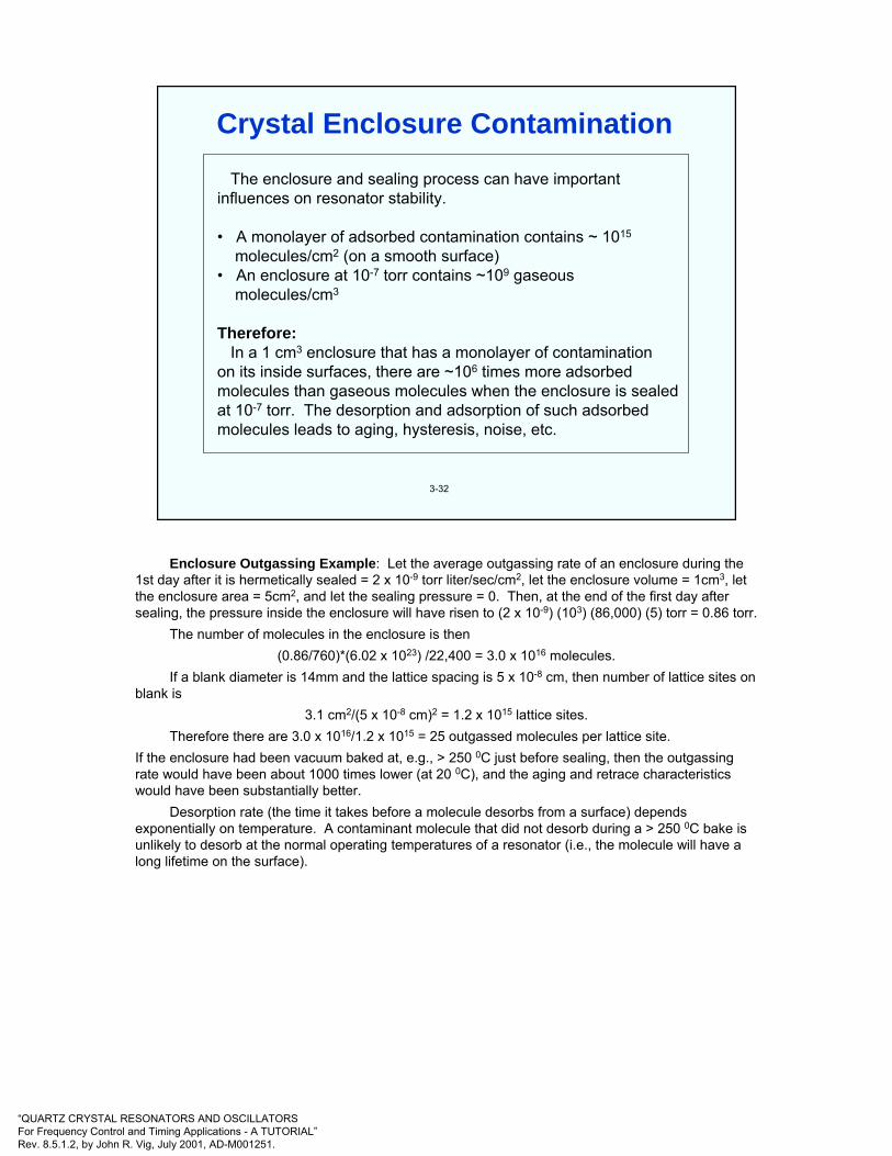
“QUARTZ CRYSTAL RESONATORS AND OSCILLATORSFor Frequency Control and Timing Applications - A TUTORIAL”Rev. 8.5.1.2, by John R. Vig, July 2001, AD-M001251.
The enclosure and sealing process can have important influences on resonator stability.
• A monolayer of adsorbed contamination contains ~ 1015
molecules/cm2 (on a smooth surface)• An enclosure at 10-7 torr contains ~109 gaseous
molecules/cm3
Therefore:In a 1 cm3 enclosure that has a monolayer of contamination
on its inside surfaces, there are ~106 times more adsorbed molecules than gaseous molecules when the enclosure is sealed at 10-7 torr. The desorption and adsorption of such adsorbed molecules leads to aging, hysteresis, noise, etc.
3-32
Crystal Enclosure Contamination
Enclosure Outgassing Example: Let the average outgassing rate of an enclosure during the 1st day after it is hermetically sealed = 2 x 10⁻⁹ torr liter/sec/cm2, let the enclosure volume = 1cm3, let the enclosure area = 5cm2, and let the sealing pressure = 0. Then, at the end of the first day after sealing, the pressure inside the enclosure will have risen to (2 x 10⁻⁹) (103) (86,000) (5) torr = 0.86 torr.
The number of molecules in the enclosure is then(0.86/760)*(6.02 x 1023) /22,400 = 3.0 x 10¹⁶ molecules.
If a blank diameter is 14mm and the lattice spacing is 5 x 10⁻⁸ cm, then number of lattice sites on blank is
3.1 cm2/(5 x 10-8 cm)2 = 1.2 x 10¹⁵ lattice sites.Therefore there are 3.0 x 10¹⁶/1.2 x 1015 = 25 outgassed molecules per lattice site.
If the enclosure had been vacuum baked at, e.g., > 250 0C just before sealing, then the outgassingrate would have been about 1000 times lower (at 20 0C), and the aging and retrace characteristics would have been substantially better.
Desorption rate (the time it takes before a molecule desorbs from a surface) depends exponentially on temperature. A contaminant molecule that did not desorb during a > 250 0C bake is unlikely to desorb at the normal operating temperatures of a resonator (i.e., the molecule will have a long lifetime on the surface).
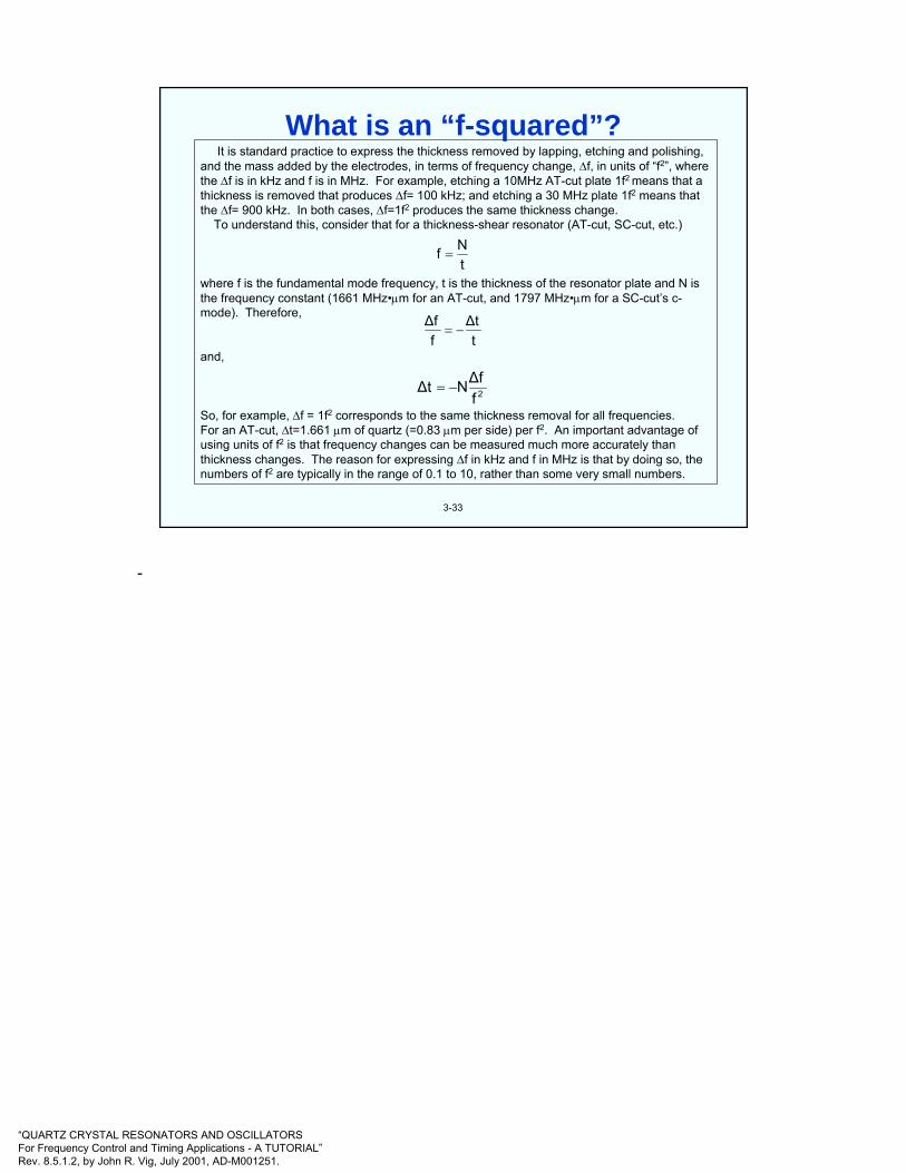
“QUARTZ CRYSTAL RESONATORS AND OSCILLATORSFor Frequency Control and Timing Applications - A TUTORIAL”Rev. 8.5.1.2, by John R. Vig, July 2001, AD-M001251.
It is standard practice to express the thickness removed by lapping, etching and polishing, and the mass added by the electrodes, in terms of frequency change, ∆f, in units of “f2”, where the ∆f is in kHz and f is in MHz. For example, etching a 10MHz AT-cut plate 1f2 means that a thickness is removed that produces ∆f= 100 kHz; and etching a 30 MHz plate 1f2 means that the ∆f= 900 kHz. In both cases, ∆f=1f2 produces the same thickness change.
To understand this, consider that for a thickness-shear resonator (AT-cut, SC-cut, etc.)
where f is the fundamental mode frequency, t is the thickness of the resonator plate and N is the frequency constant (1661 MHz•µm for an AT-cut, and 1797 MHz•µm for a SC-cut’s c-mode). Therefore,
and,
So, for example, ∆f = 1f2 corresponds to the same thickness removal for all frequencies. For an AT-cut, ∆t=1.661 µm of quartz (=0.83 µm per side) per f2. An important advantage of using units of f2 is that frequency changes can be measured much more accurately than thickness changes. The reason for expressing ∆f in kHz and f in MHz is that by doing so, the numbers of f2 are typically in the range of 0.1 to 10, rather than some very small numbers.
3-33
tNf =
t∆t
f∆f
−=
2f∆fN∆t −=
What is an “f-squared”?
-

“QUARTZ CRYSTAL RESONATORS AND OSCILLATORSFor Frequency Control and Timing Applications - A TUTORIAL”Rev. 8.5.1.2, by John R. Vig, July 2001, AD-M001251.
3-34
1880 Piezoelectric effect discovered by Jacques and Pierre Curie1905 First hydrothermal growth of quartz in a laboratory - by G. Spezia1917 First application of piezoelectric effect, in sonar1918 First use of piezoelectric crystal in an oscillator1926 First quartz crystal controlled broadcast station1927 First temperature compensated quartz cut discovered1927 First quartz crystal clock built1934 First practical temp. compensated cut, the AT-cut, developed1949 Contoured, high-Q, high stability AT-cuts developed1956 First commercially grown cultured quartz available1956 First TCXO described1972 Miniature quartz tuning fork developed; quartz watches available1974 The SC-cut (and TS/TTC-cut) predicted; verified in 19761982 First MCXO with dual c-mode self-temperature sensing
Milestones in Quartz Technology
The Frequency Control website <http://www.ieee.org/uffc/fc> contains a collection of historical papers on both quartz and atomic frequency control technologies.
W. A. Marrison, "The Evolution of the Quartz Crystal Clock," Bell System Technical Journal, Vol. 27, pp. 510-588, 1948.
F. D. Lewis, "Frequency and Time Standards," Proc. of the Institute of Radio Engineers, pp. 1046-1068, Sept. 1955.
V. E. Bottom, "A History of the Quartz Crystal Industry in the USA," Proc. 35th Annual Symposium on Frequency Control, pp. 3-12, 1981.

“QUARTZ CRYSTAL RESONATORS AND OSCILLATORSFor Frequency Control and Timing Applications - A TUTORIAL”Rev. 8.5.1.2, by John R. Vig, July 2001, AD-M001251.
3-35
Requirements:
• Small size
• Low power dissipation (including the oscillator)
• Low cost
• High stability (temperature, aging, shock, attitude)
These requirements can be met with 32,768 Hz quartztuning forks
Quartz Resonators for Wristwatches
E. Momosaki, “A Brief Review of Progress in Quartz Tuning Fork Resonators,” Proc. 1997 IEEE Int'l Frequency Control Symposium, pp. 552-565, 1997.

“QUARTZ CRYSTAL RESONATORS AND OSCILLATORSFor Frequency Control and Timing Applications - A TUTORIAL”Rev. 8.5.1.2, by John R. Vig, July 2001, AD-M001251.
3-36
32,76816,384
8,1924,0962,0481,024
512256128
643216
8421
32,768 = 215
• In an analog watch, a stepping motor receivesone impulse per second which advances the second hand by 6o, i.e., 1/60th of a circle, every second.
• Dividing 32,768 Hz by two 15 times results in 1 Hz.
• The 32,768 Hz is a compromise among size, power requirement (i.e., battery life) and stability.
Why 32,768 Hz?
-
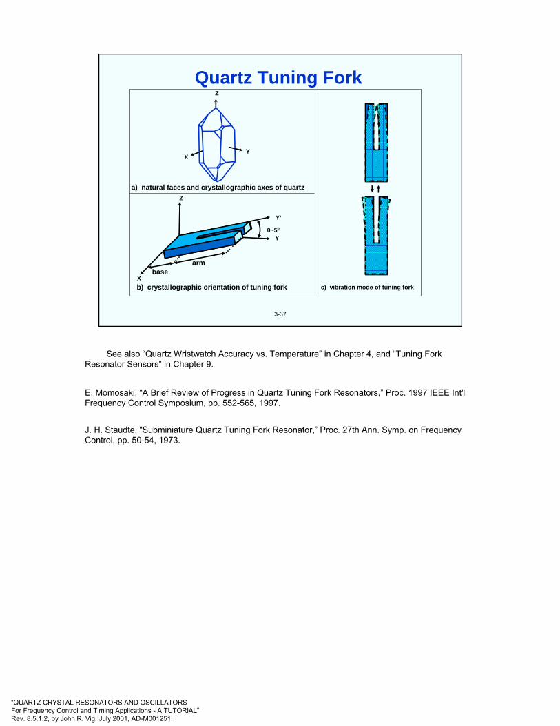
“QUARTZ CRYSTAL RESONATORS AND OSCILLATORSFor Frequency Control and Timing Applications - A TUTORIAL”Rev. 8.5.1.2, by John R. Vig, July 2001, AD-M001251.
3-37
Z
YX
Y’
0~50
Y
Z
Xbase
arm
a) natural faces and crystallographic axes of quartz
b) crystallographic orientation of tuning fork c) vibration mode of tuning fork
Quartz Tuning Fork
See also “Quartz Wristwatch Accuracy vs. Temperature” in Chapter 4, and “Tuning Fork Resonator Sensors” in Chapter 9.
E. Momosaki, “A Brief Review of Progress in Quartz Tuning Fork Resonators,” Proc. 1997 IEEE Int'l Frequency Control Symposium, pp. 552-565, 1997.
J. H. Staudte, “Subminiature Quartz Tuning Fork Resonator,” Proc. 27th Ann. Symp. on Frequency Control, pp. 50-54, 1973.
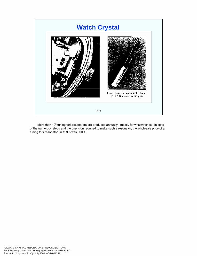
“QUARTZ CRYSTAL RESONATORS AND OSCILLATORSFor Frequency Control and Timing Applications - A TUTORIAL”Rev. 8.5.1.2, by John R. Vig, July 2001, AD-M001251.
3-38
Watch Crystal
More than 109 tuning fork resonators are produced annually - mostly for wristwatches. In spite of the numerous steps and the precision required to make such a resonator, the wholesale price of a tuning fork resonator (in 1999) was ~$0.1.
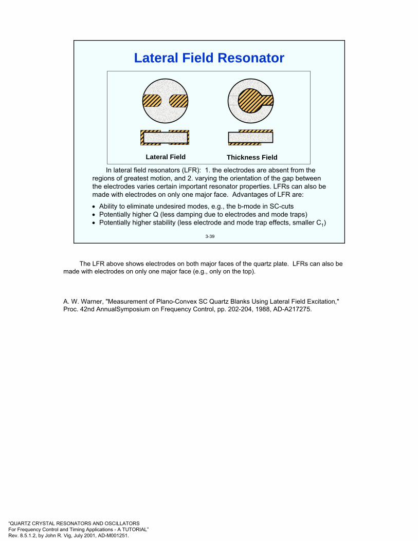
“QUARTZ CRYSTAL RESONATORS AND OSCILLATORSFor Frequency Control and Timing Applications - A TUTORIAL”Rev. 8.5.1.2, by John R. Vig, July 2001, AD-M001251.
3-39
In lateral field resonators (LFR): 1. the electrodes are absent from the regions of greatest motion, and 2. varying the orientation of the gap between the electrodes varies certain important resonator properties. LFRs can also be made with electrodes on only one major face. Advantages of LFR are:
• Ability to eliminate undesired modes, e.g., the b-mode in SC-cuts• Potentially higher Q (less damping due to electrodes and mode traps) • Potentially higher stability (less electrode and mode trap effects, smaller C1)
Lateral Field Thickness Field
Lateral Field Resonator
The LFR above shows electrodes on both major faces of the quartz plate. LFRs can also be made with electrodes on only one major face (e.g., only on the top).
A. W. Warner, "Measurement of Plano-Convex SC Quartz Blanks Using Lateral Field Excitation," Proc. 42nd AnnualSymposium on Frequency Control, pp. 202-204, 1988, AD-A217275.

“QUARTZ CRYSTAL RESONATORS AND OSCILLATORSFor Frequency Control and Timing Applications - A TUTORIAL”Rev. 8.5.1.2, by John R. Vig, July 2001, AD-M001251.
3-40
C
D1
D2
Side view of BVA2resonator construction
Side and top views ofcenter plate C
C
Quartzbridge
Electrodeless (BVA) Resonator
BVA resonators are designed primarily to minimize stresses due to the mounting structure and the instabilities due to the electrodes (see “Stresses on a Quartz Resonator Plate” and subsequent pages in the next chapter). The BVA2 structure shown above consists of three quartz plates of the same angles of cut and azimuthal orientation. The resonator plate is the plate “C” in the center. The active part of plate C is separated from the outer inactive part near the edges by means of cutouts, and the active area is connected to the inactive area by means of small quartz bridges. The outside plates D1 and D2 contact the C plate only outside the cutouts. The electrodes, deposited onto the center areas of D1 and D2, are separated from the active area of the resonator by means of small, 5 µm to 50 µm, gaps.
The best resonator short term stability measurements reported to date have been obtained with BVA resonators, i.e., σy(τ) of parts in 1014 at the flicker floor (see chapter 4).
R. J. Besson, “A New ‘Electrodeless’ Resonator Design,” Proc. 31st Ann. Symp. on Frequency Control,”pp. 147-152, 1977
R. J. Besson, J-J Boy, M. M. Maurey, “BVA Resonators and Oscillators: A Review. Relation with Space Requirements and Quartz Material Characterization,” Proc. 1995 IEEE Int’l Frequency Control Symposium, pp. 590-599, 1995

“QUARTZ CRYSTAL RESONATORS AND OSCILLATORSFor Frequency Control and Timing Applications - A TUTORIAL”Rev. 8.5.1.2, by John R. Vig, July 2001, AD-M001251.
4
CHAPTER 4Oscillator Stability
E. A. Gerber and A. Ballato, Precision Frequency Control, Academic Press, 1985
P. Kartaschoff, Frequency and Time, Academic Press, 1978.
A. Ballato, "Piezoelectric Resonators," in B. Parzen, Design of Crystal and Other Harmonic Oscillators, John Wiley & Sons, 1983.
Characterization of Clocks and Oscillators, edited by D. B. Sullivan, et al., NIST Technical Note 1337, March 1990. Time & Frequency Div., NIST, 325 Broadway, Boulder, CO 80303.
J. R. Vig & A. Ballato, "Frequency Control Devices," in Ultrasonic Instruments & Devices II, edited by R.N. Thurston, A. D. Pierce, vol. ed. E. Papadakis, Physical Acoustics Vol. XXIV, Academic Press, pp. 209-273, 1999.
T. R. Meeker, and J. R. Vig, "The Aging of Bulk Acoustic Wave Resonators, Oscillators and Filters," Proc. 45th Ann. Symp. on Frequency Control 1991, IEEE Cat. No. 91CH2965-2.
J. R. Vig & F. L. Walls, "Fundamental Limits on the Frequency Instabilities of Quartz Crystal Oscillators," Proc. 1994 IEEE Int'l Frequency Control Symposium, pp. 506-523, 1994.

“QUARTZ CRYSTAL RESONATORS AND OSCILLATORSFor Frequency Control and Timing Applications - A TUTORIAL”Rev. 8.5.1.2, by John R. Vig, July 2001, AD-M001251.
4-1
• What is one part in 1010 ? (As in 1 x 10⁻¹⁰/day aging.)• ~1/2 cm out of the circumference of the earth.• ~1/4 second per human lifetime (of ~80 years).
• Power received on earth from a GPS satellite, -160 dBW, is as “bright” as a flashlight in Los Angeles would look in New York City, ~5000 km away (neglecting earth’s curvature).
• What is -170 dB? (As in -170 dBc/Hz phase noise.)
• -170 dB = 1 part in 1017 ≈ thickness of a sheet of paper out of the total distance traveled by allthe cars in the world in a day.
The Units of Stability in Perspective
The human mind is limited in its ability to understand very small and very large numbers. Above is an attempt to make the small numbers used in the frequency and time field a bit more understandable.
GPS analogy is courtesy of Raymond Filler, March 2004.
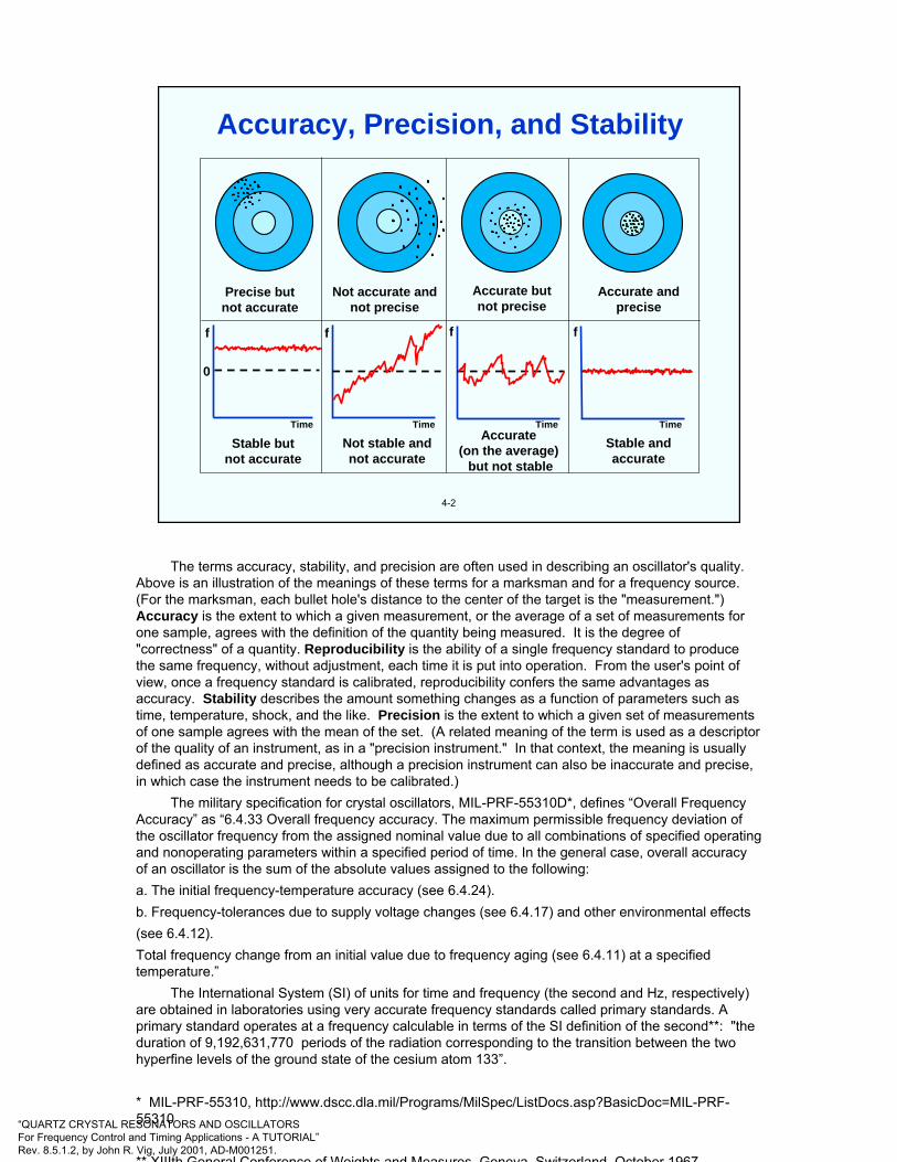
“QUARTZ CRYSTAL RESONATORS AND OSCILLATORSFor Frequency Control and Timing Applications - A TUTORIAL”Rev. 8.5.1.2, by John R. Vig, July 2001, AD-M001251.
4-2
Precise butnot accurate
Not accurate andnot precise
Accurate butnot precise
Accurate andprecise
Time TimeTimeTime
Stable butnot accurate
Not stable andnot accurate
Accurate (on the average)
but not stable
Stable andaccurate
0
f fff
Accuracy, Precision, and Stability
The terms accuracy, stability, and precision are often used in describing an oscillator's quality. Above is an illustration of the meanings of these terms for a marksman and for a frequency source. (For the marksman, each bullet hole's distance to the center of the target is the "measurement.") Accuracy is the extent to which a given measurement, or the average of a set of measurements for one sample, agrees with the definition of the quantity being measured. It is the degree of "correctness" of a quantity. Reproducibility is the ability of a single frequency standard to produce the same frequency, without adjustment, each time it is put into operation. From the user's point of view, once a frequency standard is calibrated, reproducibility confers the same advantages as accuracy. Stability describes the amount something changes as a function of parameters such as time, temperature, shock, and the like. Precision is the extent to which a given set of measurements of one sample agrees with the mean of the set. (A related meaning of the term is used as a descriptor of the quality of an instrument, as in a "precision instrument." In that context, the meaning is usually defined as accurate and precise, although a precision instrument can also be inaccurate and precise, in which case the instrument needs to be calibrated.)
The military specification for crystal oscillators, MIL-PRF-55310D*, defines “Overall Frequency Accuracy” as “6.4.33 Overall frequency accuracy. The maximum permissible frequency deviation of the oscillator frequency from the assigned nominal value due to all combinations of specified operating and nonoperating parameters within a specified period of time. In the general case, overall accuracy of an oscillator is the sum of the absolute values assigned to the following:a. The initial frequency-temperature accuracy (see 6.4.24).b. Frequency-tolerances due to supply voltage changes (see 6.4.17) and other environmental effects(see 6.4.12).Total frequency change from an initial value due to frequency aging (see 6.4.11) at a specified temperature.”
The International System (SI) of units for time and frequency (the second and Hz, respectively) are obtained in laboratories using very accurate frequency standards called primary standards. A primary standard operates at a frequency calculable in terms of the SI definition of the second**: "the duration of 9,192,631,770 periods of the radiation corresponding to the transition between the two hyperfine levels of the ground state of the cesium atom 133”.
* MIL-PRF-55310, http://www.dscc.dla.mil/Programs/MilSpec/ListDocs.asp?BasicDoc=MIL-PRF-55310
** XIIIth General Conference of Weights and Measures Geneva Switzerland October 1967

“QUARTZ CRYSTAL RESONATORS AND OSCILLATORSFor Frequency Control and Timing Applications - A TUTORIAL”Rev. 8.5.1.2, by John R. Vig, July 2001, AD-M001251.
4-3
Time• Short term (noise)• Intermediate term (e.g., due to oven fluctuations)• Long term (aging)
Temperature• Static frequency vs. temperature• Dynamic frequency vs. temperature (warmup, thermal shock)• Thermal history ("hysteresis," "retrace")
Acceleration• Gravity (2g tipover) • Acoustic noise• Vibration • Shock
Ionizing radiation• Steady state • Photons (X-rays, γ-rays)• Pulsed • Particles (neutrons, protons, electrons)
Other• Power supply voltage • Humidity • Magnetic field• Atmospheric pressure (altitude) • Load impedance
Influences on Oscillator Frequency
Many factors influence the frequency stability of an oscillator. Changes in the environment can cause especially large instabilities. For example, orders of magnitude (tens of dBs) changes can be observed when the phase noise of an oscillator is measured in a quiet laboratory environment, and in a vibrating environment, such as a moving vehicle.

“QUARTZ CRYSTAL RESONATORS AND OSCILLATORSFor Frequency Control and Timing Applications - A TUTORIAL”Rev. 8.5.1.2, by John R. Vig, July 2001, AD-M001251.
4-4
810Xff∆
3
2
1
0
-1
-2
-3
t0 t1 t2 t3 t4
TemperatureStep
Vibration Shock
OscillatorTurn Off
&Turn On
2-gTipover
Radiation
Timet5 t6 t7 t8
Aging
Off
On
Short-TermInstability
Idealized Frequency-Time-Influence Behavior
Shown above are the major types of oscillator frequency instabilities. The pages that follow show each of the changes, and some others, in more detail.

“QUARTZ CRYSTAL RESONATORS AND OSCILLATORSFor Frequency Control and Timing Applications - A TUTORIAL”Rev. 8.5.1.2, by John R. Vig, July 2001, AD-M001251.
4-5
5 10 15 20 25 Time (days)
Short-term instability(Noise)
∆f/f
(ppm
)
30
25
20
15
10
Aging and Short-Term Stability
The difference between aging and short-term instability, i.e., noise, is illustrated above. One is a systematic effect that is observed over long periods of time (days to years), whereas the other is random, observed over periods that are typically measured in fractions of a second to minutes. Over periods of hours, a combination of systematic and random effects are usually observed. The frequency vs. time characteristics over such periods often appear to be random walk (at least some of which is usually environmentally caused).
"Aging" and "drift" have occasionally been used interchangeably in the frequency control literature. However, in 1990, recognizing the "need for common terminology for the unambiguous specification and description of frequency and time standard systems," the CCIR adopted a glossary of terms and definitions. According to this glossary, aging is "the systematic change in frequency with time due to internal changes in the oscillator." Added to the definition is: "Note - It is the frequency change with time when factors external to the oscillator (environment, power supply, etc.) are kept constant." Drift is defined as "the systematic change in frequency with time of an oscillator." Drift is due to a combination of factors, i.e., it due to aging plus changes in the environment and other factors external to the oscillator. Aging is what one specifies and what one measures during oscillator evaluation. Drift is what one observes in an application. For example, the drift of an oscillator in a spacecraft is due to (the algebraic sum of) aging and frequency changes due to radiation, temperature changes in the spacecraft, and power supply changes.
CCIR Recommendation No. 686, “[TF.686-1] Glossary,” CCIR 17th Plenary Assembly, Vol. VII, "Standard Frequency and Time Signals (Study Group 7)," 1990. Consultative Committee on International Radio (CCIR); copies available from: International Telecommunications Union, General Secretariat - Sales Section, Place des Nations, CH-1211 Geneva, Switzerland. http://www.itu.int/itudoc/itu-r/rec/tf/
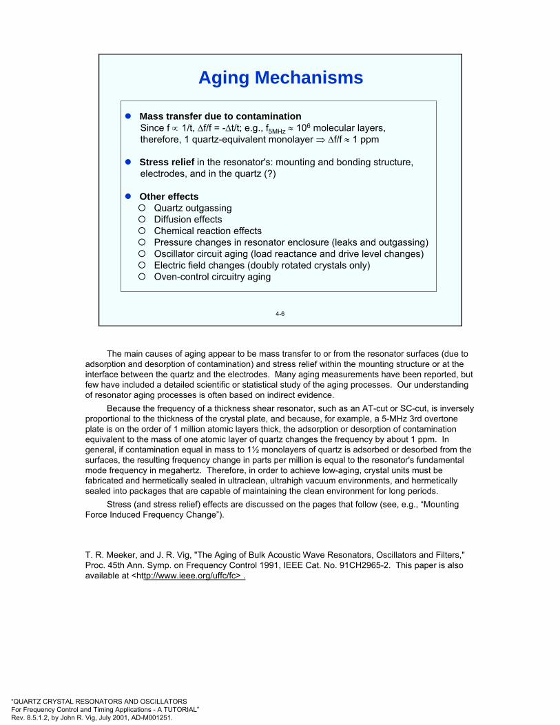
“QUARTZ CRYSTAL RESONATORS AND OSCILLATORSFor Frequency Control and Timing Applications - A TUTORIAL”Rev. 8.5.1.2, by John R. Vig, July 2001, AD-M001251.
4-6
Mass transfer due to contaminationSince f ∝ 1/t, ∆f/f = -∆t/t; e.g., f5MHz ≈ 106 molecular layers,therefore, 1 quartz-equivalent monolayer ⇒ ∆f/f ≈ 1 ppm
Stress relief in the resonator's: mounting and bonding structure,electrodes, and in the quartz (?)
Other effectsQuartz outgassingDiffusion effectsChemical reaction effectsPressure changes in resonator enclosure (leaks and outgassing)Oscillator circuit aging (load reactance and drive level changes)Electric field changes (doubly rotated crystals only)Oven-control circuitry aging
Aging Mechanisms
The main causes of aging appear to be mass transfer to or from the resonator surfaces (due to adsorption and desorption of contamination) and stress relief within the mounting structure or at the interface between the quartz and the electrodes. Many aging measurements have been reported, but few have included a detailed scientific or statistical study of the aging processes. Our understanding of resonator aging processes is often based on indirect evidence.
Because the frequency of a thickness shear resonator, such as an AT-cut or SC-cut, is inversely proportional to the thickness of the crystal plate, and because, for example, a 5-MHz 3rd overtone plate is on the order of 1 million atomic layers thick, the adsorption or desorption of contamination equivalent to the mass of one atomic layer of quartz changes the frequency by about 1 ppm. In general, if contamination equal in mass to 1½ monolayers of quartz is adsorbed or desorbed from the surfaces, the resulting frequency change in parts per million is equal to the resonator's fundamental mode frequency in megahertz. Therefore, in order to achieve low-aging, crystal units must be fabricated and hermetically sealed in ultraclean, ultrahigh vacuum environments, and hermetically sealed into packages that are capable of maintaining the clean environment for long periods.
Stress (and stress relief) effects are discussed on the pages that follow (see, e.g., “Mounting Force Induced Frequency Change”).
T. R. Meeker, and J. R. Vig, "The Aging of Bulk Acoustic Wave Resonators, Oscillators and Filters," Proc. 45th Ann. Symp. on Frequency Control 1991, IEEE Cat. No. 91CH2965-2. This paper is also available at <http://www.ieee.org/uffc/fc> .
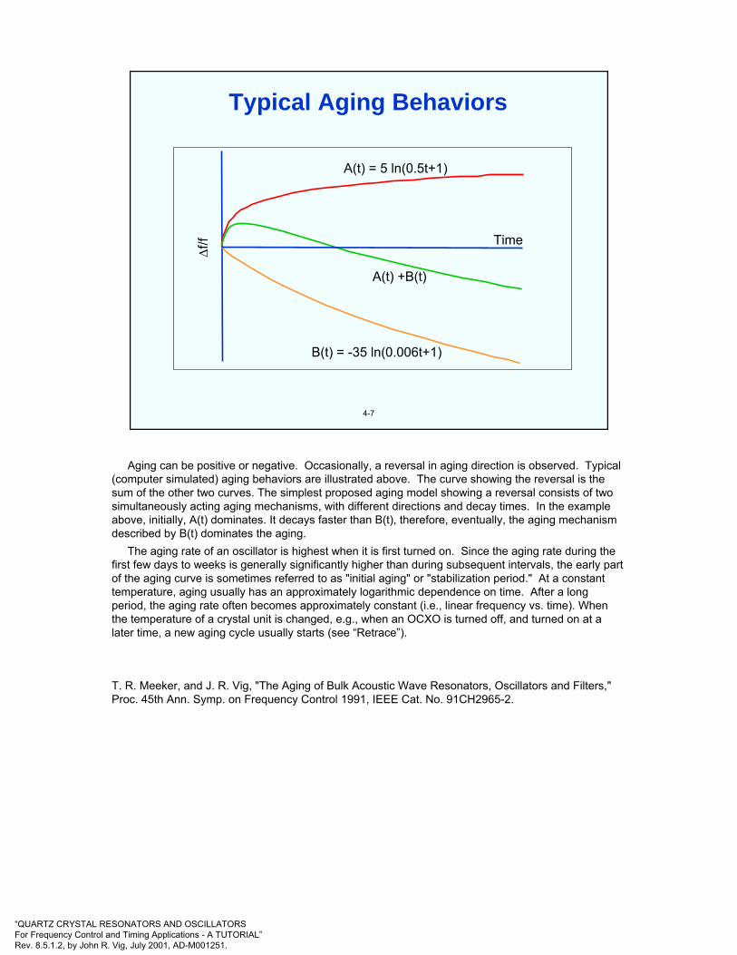
“QUARTZ CRYSTAL RESONATORS AND OSCILLATORSFor Frequency Control and Timing Applications - A TUTORIAL”Rev. 8.5.1.2, by John R. Vig, July 2001, AD-M001251.
4-7
∆f/f
A(t) = 5 ln(0.5t+1)
Time
A(t) +B(t)
B(t) = -35 ln(0.006t+1)
Typical Aging Behaviors
Aging can be positive or negative. Occasionally, a reversal in aging direction is observed. Typical (computer simulated) aging behaviors are illustrated above. The curve showing the reversal is the sum of the other two curves. The simplest proposed aging model showing a reversal consists of two simultaneously acting aging mechanisms, with different directions and decay times. In the example above, initially, A(t) dominates. It decays faster than B(t), therefore, eventually, the aging mechanism described by B(t) dominates the aging.
The aging rate of an oscillator is highest when it is first turned on. Since the aging rate during the first few days to weeks is generally significantly higher than during subsequent intervals, the early part of the aging curve is sometimes referred to as "initial aging" or "stabilization period." At a constant temperature, aging usually has an approximately logarithmic dependence on time. After a long period, the aging rate often becomes approximately constant (i.e., linear frequency vs. time). When the temperature of a crystal unit is changed, e.g., when an OCXO is turned off, and turned on at a later time, a new aging cycle usually starts (see “Retrace”).
T. R. Meeker, and J. R. Vig, "The Aging of Bulk Acoustic Wave Resonators, Oscillators and Filters," Proc. 45th Ann. Symp. on Frequency Control 1991, IEEE Cat. No. 91CH2965-2.

“QUARTZ CRYSTAL RESONATORS AND OSCILLATORSFor Frequency Control and Timing Applications - A TUTORIAL”Rev. 8.5.1.2, by John R. Vig, July 2001, AD-M001251.
4-8
Causes:
• Thermal expansion coefficient differences• Bonding materials changing dimensions upon solidifying/curing• Residual stresses due to clip forming and welding operations,
sealing• Intrinsic stresses in electrodes• Nonuniform growth, impurities & other defects during quartz
growing• Surface damage due to cutting, lapping and (mechanical) polishing
Effects:
• In-plane diametric forces• Tangential (torsional) forces, especially in 3 and 4-point mounts• Bending (flexural) forces, e.g., due to clip misalignment and
electrode stresses• Localized stresses in the quartz lattice due to dislocations,
inclusions, other impurities, and surface damage
Stresses on a Quartz Resonator Plate
There are a variety of stresses built, inadvertently, into a newly manufactured resonator. The resonator experiences additional stresses due to changes in its environment, as is discussed later in chapter 4.
It is the changes in the stresses, and the changes produced by the stresses that cause frequency instabilities. There exists evidence that, on a microscopic level, stress relief is not a continuous process. It can occur in bursts that can, possibly, contribute to noise and frequency jumps.

“QUARTZ CRYSTAL RESONATORS AND OSCILLATORSFor Frequency Control and Timing Applications - A TUTORIAL”Rev. 8.5.1.2, by John R. Vig, July 2001, AD-M001251.
4-9
Ψ XXl
ZZl
13.71
11.63
9.56
00 100 200 300 400 500 600 700 800 900
14
13
12
11
10
9
Radial
Tangential
α (Thickness) = 11.64
Orientation, Ψ, With Respect To XXl
Ther
mal
Exp
ansi
on C
oeffi
cien
t, α
, of A
T-cu
t Qua
rtz,
10-
6 /0K
Thermal Expansion Coefficients of Quartz
The thermal expansion coefficient of single crystal quartz varies with direction, as shown above*. This makes it virtually impossible to avoid stresses due to thermal expansion coefficient differences -e.g., at interfaces between the quartz plate and its electrodes and the mounting structure.
Electrodeless designs, such as the “BVA” resonator, and the “all quartz package,” attempt to eliminate these stresses by mounting the quartz resonator plate on a single crystal quartz structure of the same orientation. However, it is not the stresses but the changes in the stresses that cause instabilities, so, in other designs, compliant, spring-like mounting structures are used to minimize instabilities due to stress relief.
*Provided by Arthur Ballato, U.S. Army CECOM, private communication, circa 1978
R.J. Besson, “A New Electrodeless Resonator Design,” Proc. 31st Ann. Symp. On Frequency Control, pp. 147-152, 1977.
T.E. Parker, J. Callerame and G.R. Montress, “A New All Quartz Package For SAW Devices,” Proc. 39th Ann. Symp. on Frequency Control, pp. 519-525, 1985.
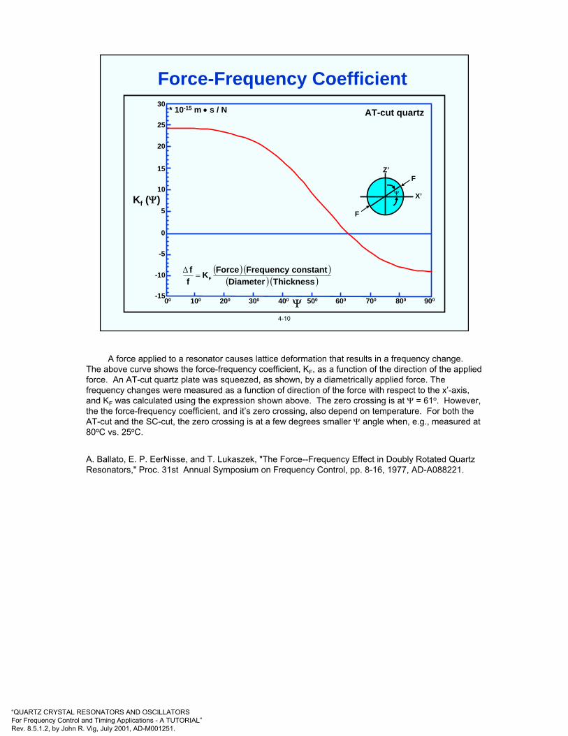
“QUARTZ CRYSTAL RESONATORS AND OSCILLATORSFor Frequency Control and Timing Applications - A TUTORIAL”Rev. 8.5.1.2, by John R. Vig, July 2001, AD-M001251.
4-10
* 10-15 m • s / N AT-cut quartz
Z’F
X’
F
30
25
20
15
10
5
0
-5
-10
-1500 100 200 300 400 500 600 700 800 900Ψ
Kf (Ψ)
( ) ( )( ) ( )ThicknessDiameter
constantFrequencyForceKff
F=∆
Ψ
Force-Frequency Coefficient
A force applied to a resonator causes lattice deformation that results in a frequency change. The above curve shows the force-frequency coefficient, KF, as a function of the direction of the applied force. An AT-cut quartz plate was squeezed, as shown, by a diametrically applied force. The frequency changes were measured as a function of direction of the force with respect to the x’-axis, and KF was calculated using the expression shown above. The zero crossing is at Ψ = 61o. However, the the force-frequency coefficient, and it’s zero crossing, also depend on temperature. For both the AT-cut and the SC-cut, the zero crossing is at a few degrees smaller Ψ angle when, e.g., measured at 80oC vs. 25oC.
A. Ballato, E. P. EerNisse, and T. Lukaszek, "The Force--Frequency Effect in Doubly Rotated Quartz Resonators," Proc. 31st Annual Symposium on Frequency Control, pp. 8-16, 1977, AD-A088221.

“QUARTZ CRYSTAL RESONATORS AND OSCILLATORSFor Frequency Control and Timing Applications - A TUTORIAL”Rev. 8.5.1.2, by John R. Vig, July 2001, AD-M001251.
4-11
X-ray topograph of an AT-cut, two-point mounted resonator. The topographshows the lattice deformation due to the stresses caused by the mounting clips.
Strains Due To Mounting Clips
R. A. Young, R. B. Belser, A. L. Bennett, W. H. Hicklin, J. C. Meaders, and C. E. Wagner, "Special X-ray Studies of Quartz Frequency Control Units," Proc. 19th Annual Symposium on Frequency Control, pp. 23-41, 1965, AD-471229.
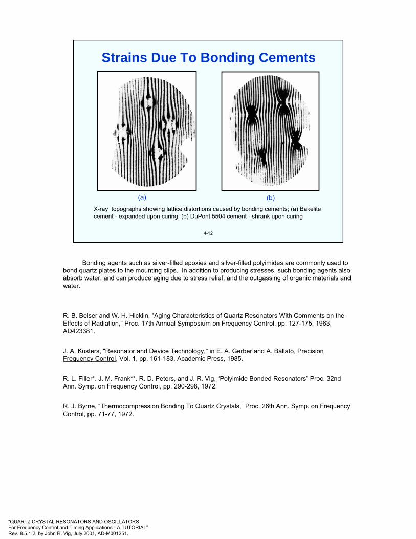
“QUARTZ CRYSTAL RESONATORS AND OSCILLATORSFor Frequency Control and Timing Applications - A TUTORIAL”Rev. 8.5.1.2, by John R. Vig, July 2001, AD-M001251.
4-12
X-ray topographs showing lattice distortions caused by bonding cements; (a) Bakelitecement - expanded upon curing, (b) DuPont 5504 cement - shrank upon curing
(a) (b)
Strains Due To Bonding Cements
Bonding agents such as silver-filled epoxies and silver-filled polyimides are commonly used to bond quartz plates to the mounting clips. In addition to producing stresses, such bonding agents also absorb water, and can produce aging due to stress relief, and the outgassing of organic materials and water.
R. B. Belser and W. H. Hicklin, "Aging Characteristics of Quartz Resonators With Comments on the Effects of Radiation," Proc. 17th Annual Symposium on Frequency Control, pp. 127-175, 1963, AD423381.
J. A. Kusters, "Resonator and Device Technology," in E. A. Gerber and A. Ballato, Precision Frequency Control, Vol. 1, pp. 161-183, Academic Press, 1985.
R. L. Filler*. J. M. Frank**. R. D. Peters, and J. R. Vig, “Polyimide Bonded Resonators” Proc. 32nd Ann. Symp. on Frequency Control, pp. 290-298, 1972.
R. J. Byrne, “Thermocompression Bonding To Quartz Crystals,” Proc. 26th Ann. Symp. on Frequency Control, pp. 71-77, 1972.

“QUARTZ CRYSTAL RESONATORS AND OSCILLATORSFor Frequency Control and Timing Applications - A TUTORIAL”Rev. 8.5.1.2, by John R. Vig, July 2001, AD-M001251.
4-13
The force-frequency coefficient, KF (ψ), is defined by
Maximum KF (AT-cut) = 24.5 x 10⁻¹⁵ m-s/N at ψ = 0o
Maximum KF (SC-cut) = 14.7 x 10⁻¹⁵ m-s/N at ψ = 44o
As an example, consider a 5 MHz 3rd overtone, 14 mm diameter resonator. Assuming the presence of diametrical forces only, (1 gram = 9.81 x 10⁻³
newtons),
2.9 x 10⁻⁸ per gram for an AT-cut resonator1.7 x 10-8 per gram for an SC-cut resonator
0 at ψ = 61o for an AT-cut resonator, and at ψ = 82o for an SC-cut.
F
F
X’
Z’
( ) ( )( ) ( )ThicknessDiameter
ttanconsFrequencyForceKff
F
−=
∆
=⎟⎠⎞
⎜⎝⎛
Maxf∆f
=⎟⎠⎞
⎜⎝⎛
Minf∆f
Ψ
Mounting Force Induced Frequency Change
The mounting structure can produce not only in-plane diametric forces but also tangential (torsional) forces, especially in 3 and 4-point mounts, and bending (flexural) forces, e.g., due to clip misalignment and electrode stresses. These stresses produce frequency shifts, and the changes in these stresses result in frequency aging.
A. Ballato, E. P. EerNisse, and T. Lukaszek, "The Force--Frequency Effect in Doubly Rotated Quartz Resonators," Proc. 31st Annual Symposium on Frequency Control, pp. 8-16, 1977, AD-A088221.
E. D. Fletcher and A. J. Douglas, “A Comparison Of The Effects Of Bending Moments On TheVibrations Of AT And SC (or TTC) Cuts Of Quartz,” Proc. 33rd Annual Symposium onFrequency Control, pp. 346-350, 1979.

“QUARTZ CRYSTAL RESONATORS AND OSCILLATORSFor Frequency Control and Timing Applications - A TUTORIAL”Rev. 8.5.1.2, by John R. Vig, July 2001, AD-M001251.
4-14
When 22 MHz fundamental mode AT-cut resonators were reprocessed so as to vary the bonding orientations, the frequency vs. temperature characteristics of the resonators changed as if the angles of cut had been changed. The resonator blanks were 6.4 mm in diameter plano-plano, and were bonded to low-stress mounting clips by nickel electrobonding.
Bonding orientation, Ψ
App
aren
t ang
le s
hift
(min
utes
)
•
• Blank No. 7Blank No. 8
Z’
X’
6’
5’
4’
3’
2’
1’
0’
-1’
-2’
300 600 900
•
•
•
•
••
•
Ψ
Bonding Strains Induced Frequency Changes
The mounting and bonding stresses can affect the f vs. T of resonators. The experimental results shown above demonstrate that the same quartz plate can exhibit a range of f vs. T characteristics depending on the orientation of the bonding stresses. (Thicker plates and more compliant bonding agents produce smaller apparent angle shifts.)
R. L. Filler, and J. R. Vig, "The Effect of Bonding on the Frequency vs. Temperature Characteristics of AT-cut Resonators," Proc. 30th Annual Symposium on Frequency Control, pp. 264-268, 1976, AD-046089.
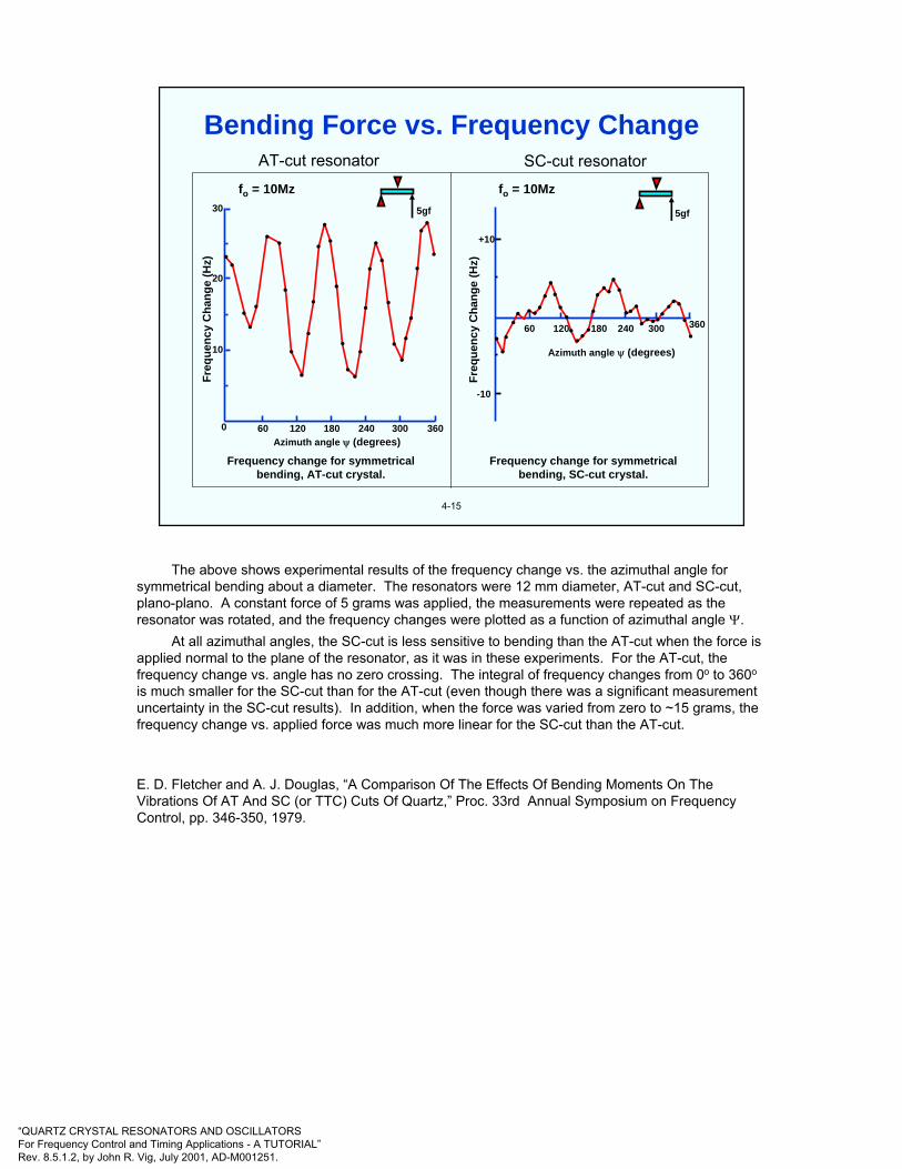
“QUARTZ CRYSTAL RESONATORS AND OSCILLATORSFor Frequency Control and Timing Applications - A TUTORIAL”Rev. 8.5.1.2, by John R. Vig, July 2001, AD-M001251.
AT-cut resonator SC-cut resonator
4-15
5gf
fo = 10Mz fo = 10Mz
5gfFr
eque
ncy
Cha
nge
(Hz)
Freq
uenc
y C
hang
e (H
z)
30
20
10
0 240120 18060 300 360
240120 18060 300 360
+10
-10
Azimuth angle ψ (degrees)
Azimuth angle ψ (degrees)
Frequency change for symmetrical bending, SC-cut crystal.
Frequency change for symmetrical bending, AT-cut crystal.
•
••
•
•
• •
•
••
•
•
•••
•
•
• •
•
•
•
••
•
••••
•
••
•
•••••
••••••••
•••
•••••
•••••
••••••••
••
Bending Force vs. Frequency Change
The above shows experimental results of the frequency change vs. the azimuthal angle for symmetrical bending about a diameter. The resonators were 12 mm diameter, AT-cut and SC-cut, plano-plano. A constant force of 5 grams was applied, the measurements were repeated as the resonator was rotated, and the frequency changes were plotted as a function of azimuthal angle Ψ.
At all azimuthal angles, the SC-cut is less sensitive to bending than the AT-cut when the force is applied normal to the plane of the resonator, as it was in these experiments. For the AT-cut, the frequency change vs. angle has no zero crossing. The integral of frequency changes from 0o to 360o
is much smaller for the SC-cut than for the AT-cut (even though there was a significant measurement uncertainty in the SC-cut results). In addition, when the force was varied from zero to ~15 grams, the frequency change vs. applied force was much more linear for the SC-cut than the AT-cut.
E. D. Fletcher and A. J. Douglas, “A Comparison Of The Effects Of Bending Moments On The Vibrations Of AT And SC (or TTC) Cuts Of Quartz,” Proc. 33rd Annual Symposium on Frequency Control, pp. 346-350, 1979.
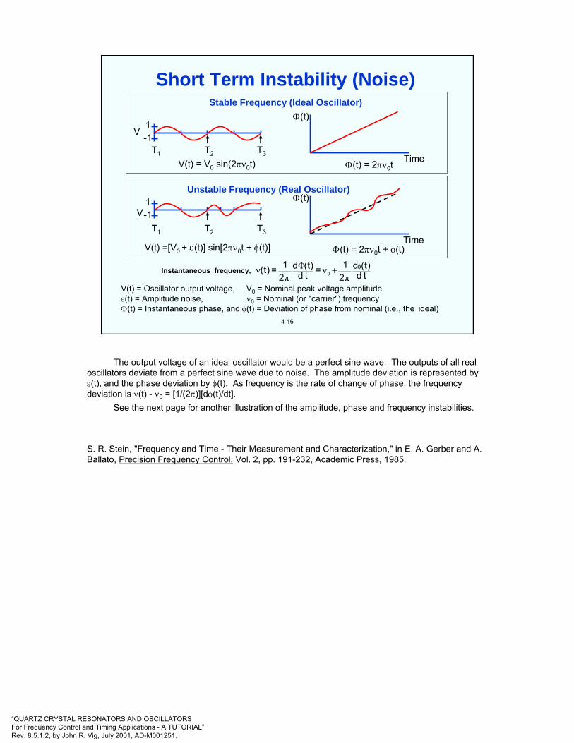
“QUARTZ CRYSTAL RESONATORS AND OSCILLATORSFor Frequency Control and Timing Applications - A TUTORIAL”Rev. 8.5.1.2, by John R. Vig, July 2001, AD-M001251.
4-16
Stable Frequency (Ideal Oscillator)
Unstable Frequency (Real Oscillator)
Time
Φ(t)
Time
Φ(t)
V1-1
T1 T2 T3
1-1
T1 T2 T3
V(t) = V0 sin(2πν0t)
V(t) =[V0 + ε(t)] sin[2πν0t + φ(t)]
Φ(t) = 2πν0t
Φ(t) = 2πν0t + φ(t)
V(t) = Oscillator output voltage, V0 = Nominal peak voltage amplitudeε(t) = Amplitude noise, ν0 = Nominal (or "carrier") frequencyΦ(t) = Instantaneous phase, and φ(t) = Deviation of phase from nominal (i.e., the ideal)
t d)t(d
21= t d
)t(d21 = )t( 0
φ+ννπ
Φπ
frequency, ousInstantane
V
Short Term Instability (Noise)
The output voltage of an ideal oscillator would be a perfect sine wave. The outputs of all real oscillators deviate from a perfect sine wave due to noise. The amplitude deviation is represented by ε(t), and the phase deviation by φ(t). As frequency is the rate of change of phase, the frequencydeviation is ν(t) - ν0 = [1/(2π)][dφ(t)/dt].
See the next page for another illustration of the amplitude, phase and frequency instabilities.
S. R. Stein, "Frequency and Time - Their Measurement and Characterization," in E. A. Gerber and A.Ballato, Precision Frequency Control, Vol. 2, pp. 191-232, Academic Press, 1985.

“QUARTZ CRYSTAL RESONATORS AND OSCILLATORSFor Frequency Control and Timing Applications - A TUTORIAL”Rev. 8.5.1.2, by John R. Vig, July 2001, AD-M001251.
4-17
Amplitudeinstability
Frequencyinstability
Phaseinstability
-Vo
ltage
+0
Time
Instantaneous Output Voltage of an Oscillator
As shown on the previous page, the instantaneous output voltage of a precision oscillator can be expressed as
V(t) = (Vo + ε(t)) sin(2πνot + φ(t)),
where Vo is the nominal peak voltage amplitude, ε(t) is the deviation from the nominal amplitude, νo is the nominal frequency, and φ(t) is the phase deviation from the nominal phase 2πνot. The figure illustrates a signal with amplitude, phase and frequency instabilities. Fluctuations in the peak value of the signal is the amplitude instability. Fluctuations in the zero crossings of the voltage is the phase instability. Frequency instability is the fluctuations in the period of the voltage.
In the signal shown, the frequency components of the noise are higher than the carrier frequency. This is for illustration purposes only. In general, the measures of stability apply to the frequency components of amplitude, phase and frequency instabilities which are lower in frequency than the carrier frequency.
The above figure was provided by Prof. Eva Ferre-Pikal, Univ. of Wyoming, 1999.
IEEE Standard 1139-1999
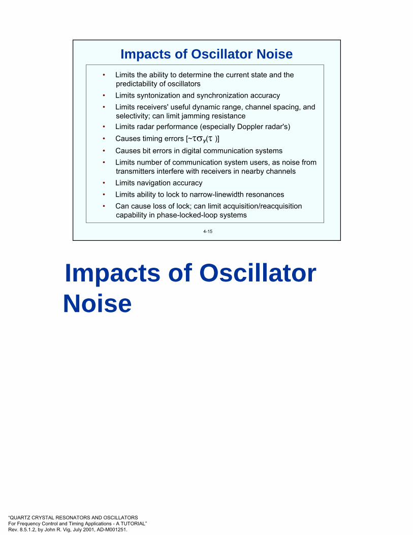
“QUARTZ CRYSTAL RESONATORS AND OSCILLATORSFor Frequency Control and Timing Applications - A TUTORIAL”Rev. 8.5.1.2, by John R. Vig, July 2001, AD-M001251.
• Limits the ability to determine the current state and the predictability of oscillators
• Limits syntonization and synchronization accuracy • Limits receivers' useful dynamic range, channel spacing, and
selectivity; can limit jamming resistance • Limits radar performance (especially Doppler radar's)• Causes timing errors [~τσy(τ )] • Causes bit errors in digital communication systems • Limits number of communication system users, as noise from
transmitters interfere with receivers in nearby channels • Limits navigation accuracy • Limits ability to lock to narrow-linewidth resonances• Can cause loss of lock; can limit acquisition/reacquisition
capability in phase-locked-loop systems
4-15
Impacts of Oscillator Noise
Impacts of Oscillator Noise
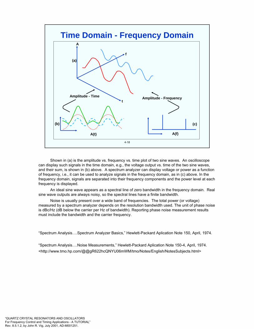
“QUARTZ CRYSTAL RESONATORS AND OSCILLATORSFor Frequency Control and Timing Applications - A TUTORIAL”Rev. 8.5.1.2, by John R. Vig, July 2001, AD-M001251.
4-18
(b)
A(t) A(f)
(c)
Amplitude - Time Amplitude - Frequencyt
A
(a)
f
Time Domain - Frequency Domain
Shown in (a) is the amplitude vs. frequency vs. time plot of two sine waves. An oscilloscope can display such signals in the time domain, e.g., the voltage output vs. time of the two sine waves, and their sum, is shown in (b) above. A spectrum analyzer can display voltage or power as a function of frequency, i.e., it can be used to analyze signals in the frequency domain, as in (c) above. In the frequency domain, signals are separated into their frequency components and the power level at each frequency is displayed.
An ideal sine wave appears as a spectral line of zero bandwidth in the frequency domain. Real sine wave outputs are always noisy, so the spectral lines have a finite bandwidth.
Noise is usually present over a wide band of frequencies. The total power (or voltage) measured by a spectrum analyzer depends on the resolution bandwidth used. The unit of phase noise is dBc/Hz (dB below the carrier per Hz of bandwidth). Reporting phase noise measurement results must include the bandwidth and the carrier frequency.
“Spectrum Analysis….Spectrum Analyzer Basics,” Hewlett-Packard Aplication Note 150, April, 1974.
“Spectrum Analysis….Noise Measurements,” Hewlett-Packard Aplication Note 150-4, April, 1974.<http://www.tmo.hp.com/@@gR622hcQNYU06mWM/tmo/Notes/English/NotesSubjects.html>

“QUARTZ CRYSTAL RESONATORS AND OSCILLATORSFor Frequency Control and Timing Applications - A TUTORIAL”Rev. 8.5.1.2, by John R. Vig, July 2001, AD-M001251.
The irregular, random dancing motions of tiny solid particles suspended in a liquid were observed in the 18th century, and the phenomenon was later described by Robert Brown. The effect, now called Brownian motion, was explained by Einstein. It was theoretically predicted and experimentally verified by J. B. Johnson (at the output of an audio amplifier) that the Brownian motion of electrons would lead to random voltages at the terminals of a resistor.
Johnson noise, also called thermal noise, is the basic limit in the amplification of weak signals, and it also limits the noise of crystal oscillators, due to the equivalent series resistance of the resonator, and due to the resistances of other components in the sustaining circuit. According to the equipartition law of Maxwell and Boltzmann, under thermal equilibrium, the energy associated with a degree of freedom of a system is kT/2 = 2 x 10-21 J per degree of freedom. It can be shown that a pure resistance R is a white thermal noise source with available power = kT = 4 x 10-21 W/Hz = -204 dBW/Hz = -174 dBm/Hz (dBm is dB referenced to one mW).
J. R. Vig & F. L. Walls, "Fundamental Limits on the Frequency Instabilities of Quartz Crystal Oscillators," Proc. 1994 IEEE Int'l Frequency Control Symposium, pp. 506-523, 1994.
W. R. Bennett, Electrical Noise, McGraw-Hill Book Co., New York, 1960.
P. H. Handel, “Quantum 1/f Quartz Resonator Theory Versus Experiment,” Proc. 1999 IEEE Frequency Control Symp.
Y.-K. Yong and J. R. Vig, “Resonator Surface Contamination - A Cause of Frequency Fluctuations?,”IEEE Tr. Ultrason. Ferroelec. Freq. Contr., vol. UFFC-36, No. 4, pp. 452-458, July 1989.
R. L. Filler, “The Acceleration Sensitivity of Quartz Crystal Oscillators: A Review,” IEEE Tr. Ultrason. Ferroelec. Freq. Contr., vol. UFFC-35, pp. 297-305, 1988.
4-19
Johnson noise (thermally induced charge fluctuations, i.e., "thermal emf” inresistive elements)
Phonon scattering by defects & quantum fluctuations (related to Q)
Noise due to oscillator circuitry (active and passive components)
Temperature fluctuations- thermal transient effects- activity dips at oven set-point
Random vibration
Fluctuations in the number of adsorbed molecules
Stress relief, fluctuations at interfaces (quartz, electrode, mount, bond)
Shot noise in atomic frequency standards
? ? ?
Causes of Short Term Instabilities

“QUARTZ CRYSTAL RESONATORS AND OSCILLATORSFor Frequency Control and Timing Applications - A TUTORIAL”Rev. 8.5.1.2, by John R. Vig, July 2001, AD-M001251.
4-20
Measure Symbol
Two-sample deviation, also called “Allan deviation”Spectral density of phase deviationsSpectral density of fractional frequency deviationsPhase noise
* Most frequently found on oscillator specification sheets
σy(τ)*Sφ(f)Sy(f)L(f)*
f2Sφ(f) = ν2Sy(f); L(f) ≡ ½ [Sφ(f)] (per IEEE Std. 1139),
and
Where τ = averaging time, ν = carrier frequency, and f = offset or Fourier frequency, or “frequency from the carrier”.
( ))df((f)sinS2)( 4
022y τπ
πντ=τ ∫
∞
φ fσ
Short-Term Stability Measures
IEEE Standard 1139 is the standard for characterizing measurements of frequency, phase, and amplitude instabilities. The standard measure for characterizing phase and frequency instabilities in the frequency domain is L(f), defined as one half of the double-sideband spectral density of phase fluctuations. When expressed in decibels, the units of L(f) are dBc/Hz (dB below the carrier in a 1 Hz bandwidth). A device is to be characterized by a plot of L(f) versus offset frequency f. In some applications, providing L(f) versus discrete values of offset frequency is sufficient.
The standard measure for characterizing amplitude instability in the frequency domain is one half of the double-sideband spectral density of the fractional amplitude fluctuations, 1/2 Sa(f). When expressed in decibels, the units of Sa(f) are dBc/Hz.
In the time domain, the standard measure of frequency and phase instabilities is the fully overlapped Allan deviation σy(τ) - see the next few pages. A device shall be characterized by a plot of σy(τ) versus sampling time τ. In some cases, providing discrete values of σy(τ) versus τ is sufficient. The measurement system bandwidth and the total measurement time shall be indicated.
IEEE Standard 1139-1999
Characterization of Clocks and Oscillators, edited by D. B. Sullivan, et al., NIST Technical Note 1337, March 1990. Time & Frequency Div., NIST, 325 Broadway, Boulder, CO 80303.
S. R. Stein, "Frequency and Time - Their Measurement and Characterization," in E. A. Gerber and A.Ballato, Precision Frequency Control, Vol. 2, pp. 191-232, Academic Press, 1985

“QUARTZ CRYSTAL RESONATORS AND OSCILLATORSFor Frequency Control and Timing Applications - A TUTORIAL”Rev. 8.5.1.2, by John R. Vig, July 2001, AD-M001251.
4-21
Also called two-sample deviation, or square-root of the "Allan variance," it is the standard method of describing the short term stability of oscillators in the time domain. It is denoted by σy(τ),
where
The fractional frequencies, are measured over a timeinterval, τ; (yk+1 - yk) are the differences between pairs ofsuccessive measurements of y, and, ideally, < > denotes a timeaverage of an infinite number of (yk+1 - yk)2. A good estimate can be obtained by a limited number, m, of measurements (m≥100). σy(τ) generally denotes i.e.,,)m ,( 2
y τσ
.)y - y(21 = )( 2
k+1k2y ><τσ
( ) ( ) 2j
m2y
2y k1k
1j21 yy
m1)m,( −=τσ=τσ +
=∑
ffy ∆
=
Allan Deviation
At long averaging times, especially when the averaging time is a substantial fraction of the record length, “TOTALDEV” statistics yield better results than the two-sample deviation (see the Howe reference below).------------------------D. W. Allan, "Time and Frequency (Time-Domain) Characterization, Estimation, and Prediction of Precision Clocks and Oscillators," IEEE Transactions on Ultrasonics, Ferroelectrics, and Frequency Control, Vol. UFFC-34, No. 6, pp. 647-654, November 1987.
“Characterization of Clocks and Oscillators,” edited by D.B. Sullivan, D.W. Allan, D.A. Howe, F.L. Walls, NIST Technical Note 1337, March 1990.
D. A. Howe, “Total Variance Explained,” Proc. 1999 IEEE Int’l Frequency Control Symp., Joint Meeting EFTF-IEEE IFCS, pp. 1093-1099.
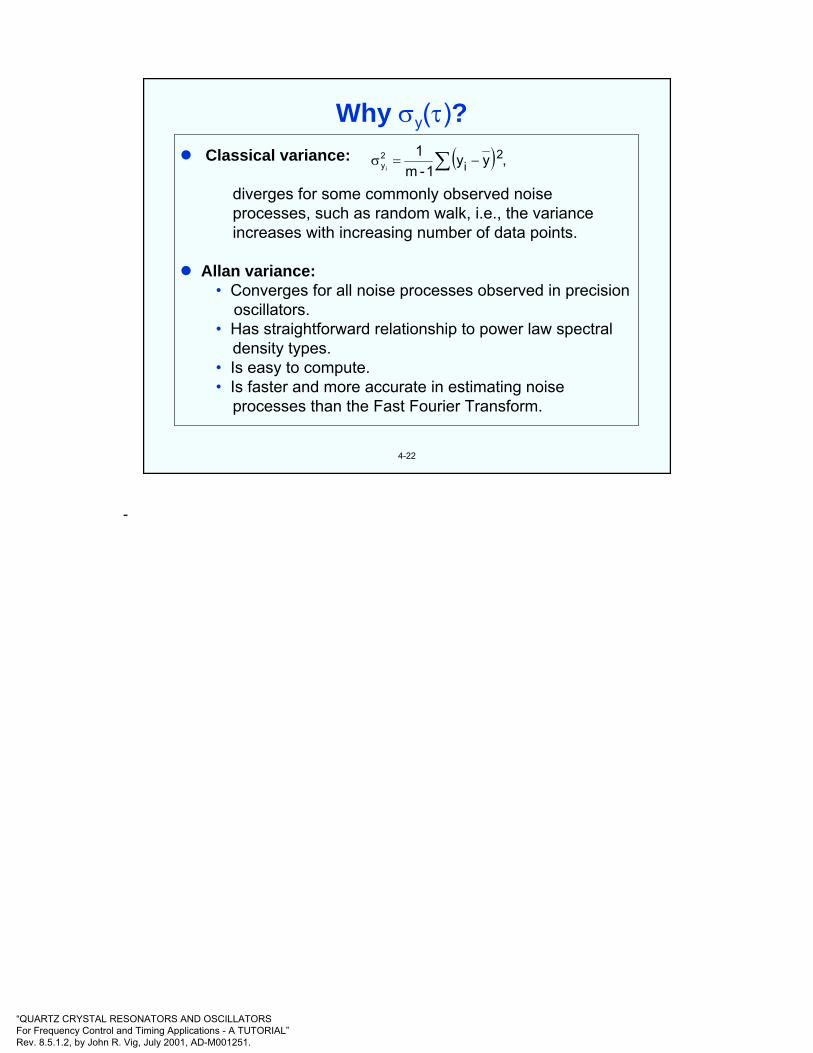
“QUARTZ CRYSTAL RESONATORS AND OSCILLATORSFor Frequency Control and Timing Applications - A TUTORIAL”Rev. 8.5.1.2, by John R. Vig, July 2001, AD-M001251.
4-22
Classical variance:
diverges for some commonly observed noise processes, such as random walk, i.e., the variance increases with increasing number of data points.
Allan variance:• Converges for all noise processes observed in precision
oscillators.• Has straightforward relationship to power law spectral
density types.• Is easy to compute.• Is faster and more accurate in estimating noise
processes than the Fast Fourier Transform.
( ) ,yy1-m
1 2i
2yi ∑ −=σ
Why σy(τ)?
-

“QUARTZ CRYSTAL RESONATORS AND OSCILLATORSFor Frequency Control and Timing Applications - A TUTORIAL”Rev. 8.5.1.2, by John R. Vig, July 2001, AD-M001251.
4-23
0.1 s averaging time3 X 10-11
0
-3 X 10-11
ff∆
100 s
1.0 s averaging time3 X 10-11
0
-3 X 10-11
ff∆
100 s
0.01 0.1 1 10 100Averaging time, τ, s
10-10
10-11
10-12
σy(τ)
Frequency Noise and σy(τ)
“The noise” is a function of the averaging time (also called “measurement time” or “tau”), as is illustrated above. For the same oscillator, the fluctuations in the frequency vs. time plot measured with a 0.1 second averaging time are larger than when measured with a 1 second averaging time. Also shown are the corresponding Allan deviations.
At short averaging times, the longer the averaging time, the lower the noise, up to the “flicker floor,” i.e., for certain noise processes (see the next four pages), the hills and valleys in the frequency vs. time data average out. Longer averaging does not help when the dominant noise process is flicker of frequency. At the flicker floor, the Allan deviation is independent of averaging time. At longer averaging times, the Allan deviation increases because the dominant noise process is random walk of frequency, for which the longer the averaging time, the larger the Allan deviation.

“QUARTZ CRYSTAL RESONATORS AND OSCILLATORSFor Frequency Control and Timing Applications - A TUTORIAL”Rev. 8.5.1.2, by John R. Vig, July 2001, AD-M001251.
4-24
*For σy(τ) to be a proper measure of random frequency fluctuations,aging must be properly subtracted from the data at long τ’s.
σy(τ)Frequency noise
Aging* andrandom walkof frequency
Short-termstability
Long-termstability
1 s 1 m 1 h Sample time τ
Time Domain Stability
“Characterization of Clocks and Oscillators,” edited by D.B. Sullivan, D.W. Allan, D.A. Howe, F.L. Walls, NIST Technical Note 1337, March 1990.

“QUARTZ CRYSTAL RESONATORS AND OSCILLATORSFor Frequency Control and Timing Applications - A TUTORIAL”Rev. 8.5.1.2, by John R. Vig, July 2001, AD-M001251.
4-25
Below the flicker of frequency noise (i.e., the “flicker floor”) region, crystal oscillators typically show τ-1 (white phase noise) dependence. Atomic standards show τ-1/2 (white frequency noise) dependence down to about the servo-loop time constant, and τ-1 dependence at less than that time constant. Typical τ’s at the start of flicker floors are: 1s for a crystal oscillator, 103s for a Rb standard and 105s for a Cs standard. At large τ’s, random walk of frequency and aging dominate.
σy(τ)τ-1
τ-1
τ0
Noise type:Whitephase
Flickerphase
Whitefreq.
Flickerfreq.
Randomwalk freq.
τ-1 τ1/2 to τ1
Power Law Dependence of σy(τ)
“Characterization of Clocks and Oscillators,” edited by D.B. Sullivan, D.W. Allan, D.A. Howe, F.L. Walls, NIST Technical Note 1337, March 1990.

“QUARTZ CRYSTAL RESONATORS AND OSCILLATORSFor Frequency Control and Timing Applications - A TUTORIAL”Rev. 8.5.1.2, by John R. Vig, July 2001, AD-M001251.
4-26
Plots show fluctuations of a quantity z(t), which can be,e.g., the output of a counter (∆f vs. t) or of a phase detector (φ[t] vs. t). The plots show simulated time-domain behaviors corresponding to the most common (power-law) spectral densities; hα is an amplitude coefficient. Note: since S∆f = f 2Sφ, e.g. white frequency noise and random walk of phase are equivalent.
Sz(f) = hαfα
α = 0
α = -1
α = -2
α = -3
Noise name
White
Flicker
Randomwalk
Plot of z(t) vs. t
Pictures of Noise
David W. Allan, “The Measurement of Frequency and Frequency Stability of Precision Oscillators,”David W. Allan, NBS Technical Note 669, May 1975.
R. F. Voss, "1/f (Flicker) Noise: A Brief Review," Proc. 33rd Annual Symposium on Frequency Control, pp. 40-46, 1979, AD-A213544.
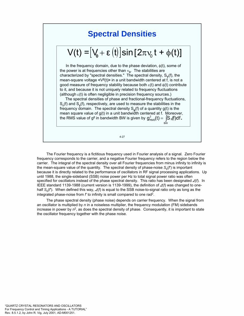
“QUARTZ CRYSTAL RESONATORS AND OSCILLATORSFor Frequency Control and Timing Applications - A TUTORIAL”Rev. 8.5.1.2, by John R. Vig, July 2001, AD-M001251.
4-27
In the frequency domain, due to the phase deviation, φ(t), some of the power is at frequencies other than ν0. The stabilities are characterized by "spectral densities." The spectral density, SV(f), the mean-square voltage <V2(t)> in a unit bandwidth centered at f, is not a good measure of frequency stability because both ε(t) and φ(t) contribute to it, and because it is not uniquely related to frequency fluctuations (although ε(t) is often negligible in precision frequency sources.)
The spectral densities of phase and fractional-frequency fluctuations, Sφ(f) and Sy(f), respectively, are used to measure the stabilities in the frequency domain. The spectral density Sg(f) of a quantity g(t) is the mean square value of g(t) in a unit bandwidth centered at f. Moreover, the RMS value of g2 in bandwidth BW is given by
( )[ ] ](t) t +2 [ sin tεV =V(t) 0 φπν+0
.ff)d(S(t)gBW
g2RMS ∫=
Spectral Densities
The Fourier frequency is a fictitious frequency used in Fourier analysis of a signal. Zero Fourier frequency corresponds to the carrier, and a negative Fourier frequency refers to the region below the carrier. The integral of the spectral density over all Fourier frequencies from minus infinity to infinity is the mean-square value of the quantity. The spectral density of phase-noise Sφ(f') is important because it is directly related to the performance of oscillators in RF signal processing applications. Up until 1988, the single-sideband (SSB) noise power per Hz to total signal power ratio was often specified for oscillators instead of the phase spectral density. This ratio has been designated L(f). In IEEE standard 1139-1988 (current version is 1139-1999), the definition of L(f) was changed to one-half Sφ(f'). When defined this way, L(f) is equal to the SSB noise-to-signal ratio only as long as the integrated phase-noise from f' to infinity is small compared to one rad2.
The phase spectral density (phase noise) depends on carrier frequency. When the signal from an oscillator is multiplied by n in a noiseless multiplier, the frequency modulation (FM) sidebands increase in power by n2, as does the spectral density of phase. Consequently, it is important to state the oscillator frequency together with the phase noise.

“QUARTZ CRYSTAL RESONATORS AND OSCILLATORSFor Frequency Control and Timing Applications - A TUTORIAL”Rev. 8.5.1.2, by John R. Vig, July 2001, AD-M001251.
4-28
( )1111 tsinAV ϕ+= ω
( )2222 tsinAV ϕ+= ωV0FilterFilter
V1V2
Trigonometric identities: sin(x)sin(y) = ½cos(x-y) - ½cos(x+y)cos(x±π/2) = sin(x)
:becomecanmixertheThen.tand,t;Let 22211121 φωΦφωΦωω +≡+≡=
• Phase detector:
• AM detector:
• Frequency multiplier:
( ) ( ) s'smallfor2
1sin
2
10V
then1,AAand2/When
2121
2121
φφφφφ
ΦΦ
−=−=
==π+=
( ) 10212110
2
A2
1then,if;cosA
2
1
thenfilter,passlowaisfiltertheand1AWhen
VV ≈≈−=
−=
φφφφ
( ) error.phaseandfrequencythedoubles2t2cosA2
1Vhen,t 11
210 ⇒+= φω
When V1 = V2 and the filter is bandpass at 2ω1
Mixer Functions
A mixer is a versatile device in frequency metrology. As shown above, the input to the mixer are two voltages, and the output is the product of those voltages. Through the application of elementary trigonometry, a mixer can be made into a phase detector, an amplitude detector, and a frequency multiplier.
P. Kartaschoff, Frequency and Time, section 3.4 “Frequency Multiplication and Division,” Academic Press, 1978.

“QUARTZ CRYSTAL RESONATORS AND OSCILLATORSFor Frequency Control and Timing Applications - A TUTORIAL”Rev. 8.5.1.2, by John R. Vig, July 2001, AD-M001251.
~
~
fO
V(t)
VR(t)
∆Φ = 900VO(t)
LPF
QuadratureMonitor*
* Or phase-locked loop
Vφ(t)
Low-NoiseAmplifier Spectrum Analyzer
Sφ(f)
Reference
DUT
4-29
Phase Detector
The device under test (DUT) and a reference source, at the same frequency and in phase quadrature (i.e., 900 out of phase), are input to a double-balanced mixer. Then,
V0(t) = V(t) VR(t) = Kcos[φ(t) - φR(t) + π/2] + Kcos[2π(ν+ νR)t + …].The low-pass filter (LPF) eliminates the second cosine term. Then,
for φR(t) << φ(t) << π/2, Vφ(t) = Kφ(t),
i.e., the phase detector converts phase fluctuations to voltage fluctuations.
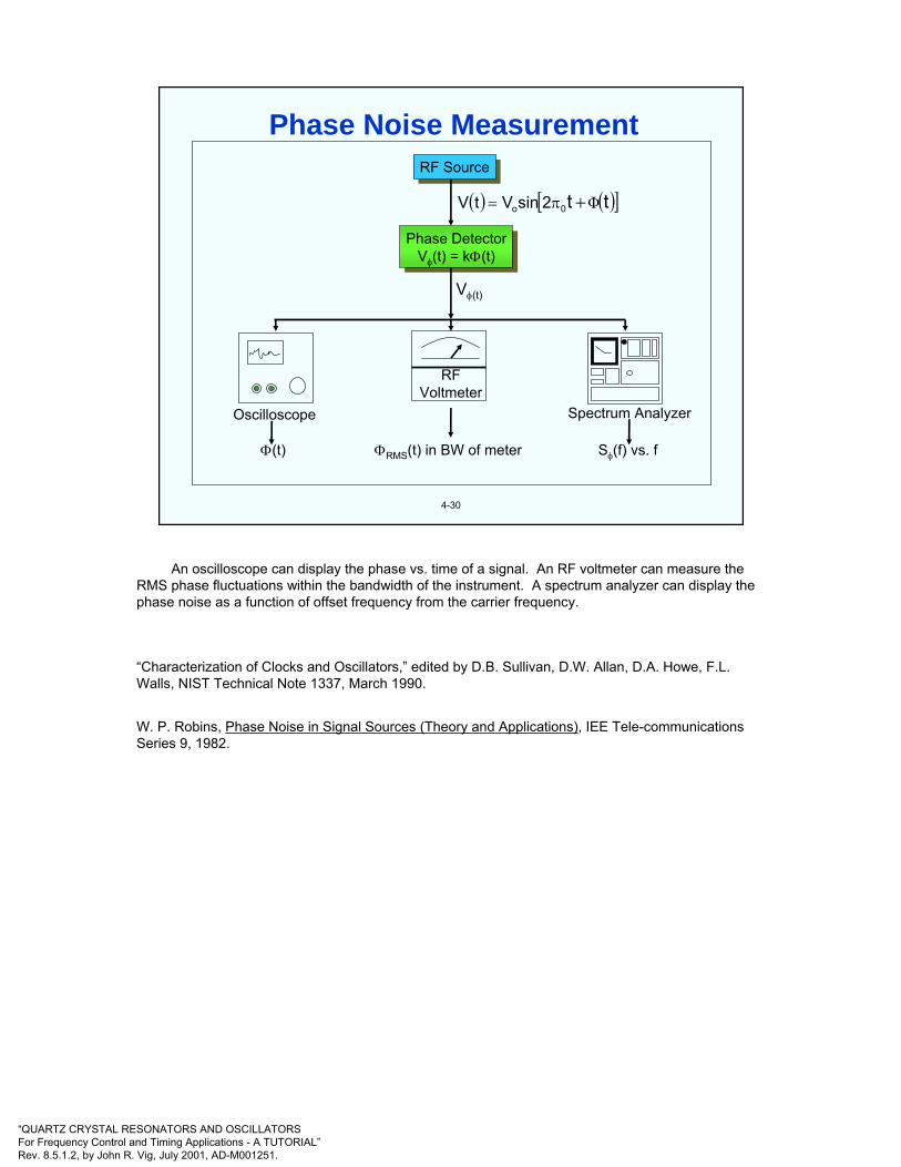
“QUARTZ CRYSTAL RESONATORS AND OSCILLATORSFor Frequency Control and Timing Applications - A TUTORIAL”Rev. 8.5.1.2, by John R. Vig, July 2001, AD-M001251.
4-30
RF SourceRF Source
Phase DetectorVφ(t) = kΦ(t)
Phase DetectorVφ(t) = kΦ(t)
Vφ(t)
RFVoltmeter
Oscilloscope Spectrum Analyzer
Φ(t) ΦRMS(t) in BW of meter Sφ(f) vs. f
( ) ( )[ ]tt0o 2sinVtV Φ+π=
Phase Noise Measurement
An oscilloscope can display the phase vs. time of a signal. An RF voltmeter can measure the RMS phase fluctuations within the bandwidth of the instrument. A spectrum analyzer can display the phase noise as a function of offset frequency from the carrier frequency.
“Characterization of Clocks and Oscillators,” edited by D.B. Sullivan, D.W. Allan, D.A. Howe, F.L. Walls, NIST Technical Note 1337, March 1990.
W. P. Robins, Phase Noise in Signal Sources (Theory and Applications), IEE Tele-communications Series 9, 1982.
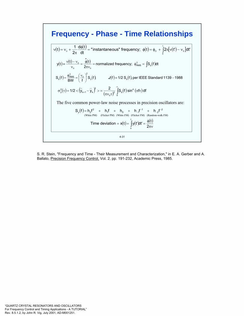
“QUARTZ CRYSTAL RESONATORS AND OSCILLATORSFor Frequency Control and Timing Applications - A TUTORIAL”Rev. 8.5.1.2, by John R. Vig, July 2001, AD-M001251.
( ) ( ) ( ) ( )[ ]dt't'2tfrequency;ous"instantane"dt
td21t
t
000 ∫ ν−νπ+φ=φ=
φπ
+ν=ν 0
( ) ( ) ( ) ( )dtfSfrequency;normalized2
ttty 2RMS ∫ φ
0
•
0
0 =φ=πνφ
=ν
ν−ν≡
( ) ( ) ( ) ( ) 19881139StandardIEEEper,fS1/2f;fSfBW
fS y
22RMS −≡⎟
⎠⎞
⎜⎝⎛ ν
=φ
= φ0
φ L
( ) ( )( )
( ) ( ) dffsinfS2yy1/2 4
02
2
k1k2y τπ
τπν=>−<=τσ ∫
∞
φ0
+
The five common power-law noise processes in precision oscillators are:
( ) 22
1101
22y fhfhhfhfhfS −
−−
− ++++=(White PM) (Flicker PM) (White FM) (Flicker FM) (Random-walk FM)
( ) ( ) ( )νπ
φ=== ∫ 2
tdt't'ytxdeviationTimet
o
4-31
Frequency - Phase - Time Relationships
S. R. Stein, "Frequency and Time - Their Measurement and Characterization," in E. A. Gerber and A.Ballato, Precision Frequency Control, Vol. 2, pp. 191-232, Academic Press, 1985.

“QUARTZ CRYSTAL RESONATORS AND OSCILLATORSFor Frequency Control and Timing Applications - A TUTORIAL”Rev. 8.5.1.2, by John R. Vig, July 2001, AD-M001251.
4-32
Consider the “simple” case of sinusoidal phase modulation at frequency fm. Then, φ(t) = φo(t)sin(2πfmt), and V(t) = Vocos[2πfct + φ(t)] = Vocos[2πfct + φ0(t)sin(πfmt)], where φo(t)= peak phase excursion, and fc=carrier frequency. Cosine of a sine function suggests a Bessel function expansion of V(t) into its components at various frequencies via the identities:
After some messy algebra, SV(f) and Sφ(f) are as shown on the next page. Then,
( )( ) ( )[ ]
( ) ( )[ ]( ) ( ) ( )
( ) ( ) ( )[ ]X12nsinBJ2BsinXsin
2nXcosBJ2(B)JBsinXcos
YXcosYXcossinXsinY
YXcosYXcos1/2cosXcosY
sinYsinXcosYcosXYXcos
12n0n
2n0
+=
∑+=
−−+=−
−++=
−=+
+
∞
=∑
( )[ ]( )[ ] ( )[ ]∑
∞
=
+=
1im
2im
20
20
m2
12
0m
fΦJ2fΦJV
fΦJVfatRatioPowerSSB
( ) ( )( ) ( ) ( )
2fS
4ffRatioPowerSSB
and1,nfor0J,f1/2J1,Jthen1,fifmm
2
m
nm10m
φ===
>===<<Φ
ΦΦ
L
Sφ(f) to SSB Power Ratio Relationship
According to IEEE Standard 1139-1999, the phase noise, L(f), is defined as
L(f) ≡ ½Sφ(f)
which is equal to the SSB power ratio only when <φ2(t)> = the integral of Sφ(f) from f = 0 to f = ∞, is less than about 0.1 rad2. Sφ(f) can always be measured unambiguously, whereas the SSB power ratio (the pre-1988 definition of phase noise) diverges close to the carrier.
The above analysis and the graph on the next page were provided by Raymond L. Filler, U.S. Army LABCOM, 1989.

“QUARTZ CRYSTAL RESONATORS AND OSCILLATORSFor Frequency Control and Timing Applications - A TUTORIAL”Rev. 8.5.1.2, by John R. Vig, July 2001, AD-M001251.
4-33
0 fm f
( ) ( ) ( )tf2cosft mm π=ΦΦ ( )fSφ ( )mf2
2Φ
( ) ( )[ ]mC0 ftf2cosVtV Φ+π=
( )[ ]( )[ ]
( ) ( )2fSφf
2fJV
fJVRatioPowerSSB mm
1im
20
20
m2
12
0
mf2iJ
≡≅
⎥⎦⎤
⎢⎣⎡ ⎟
⎠⎞⎜
⎝⎛+
=
∑∞
=
LΦΦ
Φ
SV(f)
fC-3fm fC-2fm fC-fm fC fC+fm fC+2fm fC+3fm f
( )[ ]m
20
20 fΦ2JV
( )[ ]m
21
20 fΦ2JV
( )[ ]m
22
20 fΦ2JV
( )[ ]m
23
20 fΦ2JV
Sφ(f), Sv(f) and L (f)
-

“QUARTZ CRYSTAL RESONATORS AND OSCILLATORSFor Frequency Control and Timing Applications - A TUTORIAL”Rev. 8.5.1.2, by John R. Vig, July 2001, AD-M001251.
4-34
L(ff)40 dB/decade (ff
-4)Random walk of frequency
30 dB/decade (ff-3)
Flicker of frequency20 dB/decade (ff
-2)White frequency; Random walk of phase
10 dB/decade (ff-1)
Flicker of phase0 dB/decade (ff
0)White phase
ff~BW of resonator Offset frequency(also, Fourier frequency,
sideband frequency,or modulation frequency)
Types of Phase Noise
Phase noise is important in many applications, but, the offset frequencies where the noise is important differs from application to application. For example, in many communication systems, the noise far from the carrier is important (e.g., to minimize the interference between a strong transmitted signal and a weak signal received on a neighboring channel), whereas in Doppler radar systems designed for detection of slowly moving targets, noise close to the carrier is important (see in Chapter 1, “Effect of Noise in Doppler Radar System,” and “Doppler Shifts”).
“Characterization of Clocks and Oscillators,” edited by D.B. Sullivan, D.W. Allan, D.A. Howe, F.L. Walls, NIST Technical Note 1337, March 1990.
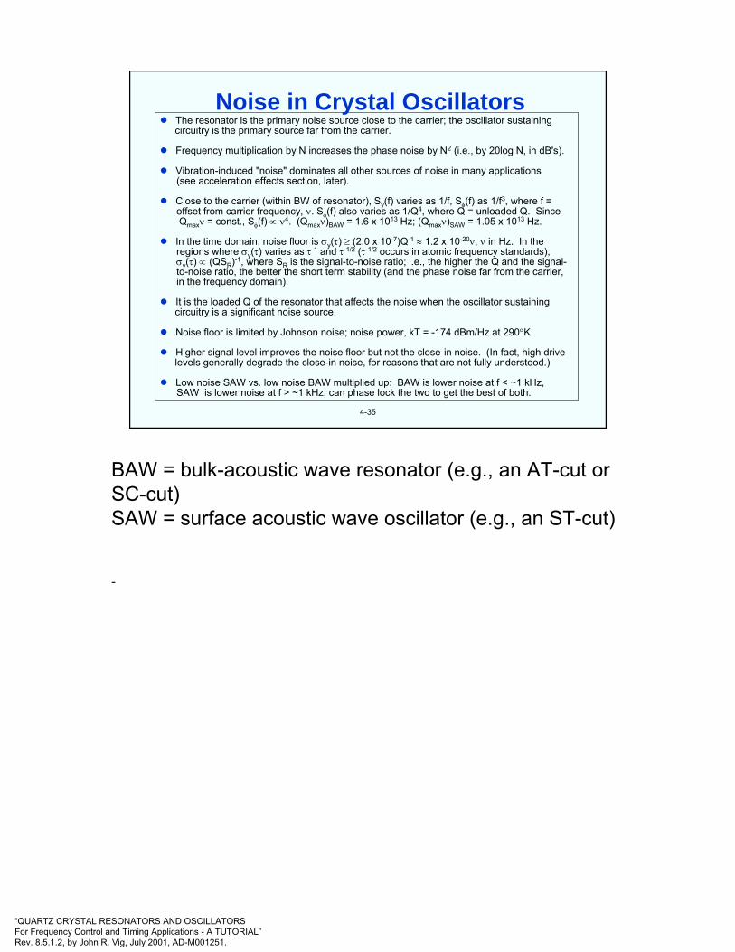
“QUARTZ CRYSTAL RESONATORS AND OSCILLATORSFor Frequency Control and Timing Applications - A TUTORIAL”Rev. 8.5.1.2, by John R. Vig, July 2001, AD-M001251.
4-35
The resonator is the primary noise source close to the carrier; the oscillator sustaining circuitry is the primary source far from the carrier.
Frequency multiplication by N increases the phase noise by N2 (i.e., by 20log N, in dB's).
Vibration-induced "noise" dominates all other sources of noise in many applications (see acceleration effects section, later).
Close to the carrier (within BW of resonator), Sy(f) varies as 1/f, Sφ(f) as 1/f3, where f =offset from carrier frequency, ν. Sφ(f) also varies as 1/Q4, where Q = unloaded Q. Since Qmaxν = const., Sφ(f) ∝ ν4. (Qmaxν)BAW = 1.6 x 10¹³ Hz; (Qmaxν)SAW = 1.05 x 10¹³ Hz.
In the time domain, noise floor is σy(τ) ≥ (2.0 x 10⁻⁷)Q-1 ≈ 1.2 x 10⁻²⁰ν, ν in Hz. In the regions where σy(τ) varies as τ-1 and τ-1/2 (τ-1/2 occurs in atomic frequency standards), σy(τ) ∝ (QSR)-1, where SR is the signal-to-noise ratio; i.e., the higher the Q and the signal-to-noise ratio, the better the short term stability (and the phase noise far from the carrier, in the frequency domain).
It is the loaded Q of the resonator that affects the noise when the oscillator sustaining circuitry is a significant noise source.
Noise floor is limited by Johnson noise; noise power, kT = -174 dBm/Hz at 290°K.
Higher signal level improves the noise floor but not the close-in noise. (In fact, high drive levels generally degrade the close-in noise, for reasons that are not fully understood.)
Low noise SAW vs. low noise BAW multiplied up: BAW is lower noise at f < ~1 kHz, SAW is lower noise at f > ~1 kHz; can phase lock the two to get the best of both.
Noise in Crystal Oscillators
BAW = bulk-acoustic wave resonator (e.g., an AT-cut or SC-cut)SAW = surface acoustic wave oscillator (e.g., an ST-cut)
-

“QUARTZ CRYSTAL RESONATORS AND OSCILLATORSFor Frequency Control and Timing Applications - A TUTORIAL”Rev. 8.5.1.2, by John R. Vig, July 2001, AD-M001251.
4-36
Offset frequency in Hz
0
-20
-40
-60
-80
-100
-120
-140
-160
10-1 100 101 102 103 104 105 106
L(f)
in d
Bc/
Hz
BAW = bulk-acoustic waveoscillator
SAW = surface acoustic wave oscillator
BAW islower noise
SAW islower noise200 5500
BAW5 MHz x 2000
BAW100 MHz x 100
SAW500 MHz x 20
Low-Noise SAW and BAW Multiplied to 10 GHz(in a nonvibrating environment)
When low noise is required in the microwave (or higher) frequency range, SAW oscillators and dielectric resonator oscillators (DROs) are sometimes used. When compared with multiplied-up (bulk-acoustic-wave) quartz oscillators, these oscillators can provide lower noise far from the carrier at the expense of poorer noise close to the carrier, poorer aging, and poorer temperature stability. SAW oscillators and DROs can provide lower noise far from the carrier because these devices can be operated at higher drive levels, thereby providing higher signal-to-noise ratios, and because the devices operate at higher frequencies, thereby minimizing the "20 log N" losses due to frequency multiplication by N. L(f) = -185 dBc/Hz noise floor (at 400 kHz from the carrier) has been achieved with a 400 MHz SAW oscillator. Of course, as is the case for high-frequency bulk-wave oscillators, such noise floors are realizable only in environments that are free of vibrations at the offset frequencies of interest.
Shown above are the phase noises (with no vibration) of three low-noise oscillators multiplied to 10 GHz: a 5 MHz bulk-acoustic-wave (BAW) oscillator, a 100 MHz BAW oscillator and a 500 MHz SAW oscillator. The SAW oscillator is better at far from the carrier; the BAW oscillators are better close to the carrier.
As shown on the next page, in the presence of vibration, it is the vibration induced phase noise that dominates the phase noise (except very far from the carrier). The device that has the lower acceleration sensitivity will have the lower phase noise, independent of the effects of frequency multiplication.
G.K. Montress & T.E. Parker,”Design and Performance of an Extremely Low Noise Surface Acoustic Wave Oscillator”, Proc. 1994 IEEE Int’l Frequency Control Symposium, pp. 365-373, 1994.

“QUARTZ CRYSTAL RESONATORS AND OSCILLATORSFor Frequency Control and Timing Applications - A TUTORIAL”Rev. 8.5.1.2, by John R. Vig, July 2001, AD-M001251.
4-37
0
-20
-40
-60
-80
-100
-120
-140
-160
10-1 100 101 102 103 104 105 106
500 MHz x 20
100 MHz x 100
BAW and SAW
5 MHz x 2000 BAW
Offset frequency in Hz
L(f)
in d
Bc
/ Hz
Vibration induced phase noise dominates the phasenoise of both (whichever has lower acceleration
sensitivity will have lower phase noise; currently,BAW can provide lower sensitivity than SAW.)
Illustration assumes 1 x 10⁻⁹/g accelerationsensitivity for both BAW and SAW, and 0.01
g2 / Hz random vibration power spectraldensity at all vibration frequencies
Low-Noise SAW and BAW Multiplied to 10 GHz(in a vibrating environment)
The solid line shows the phase noises under vibration for both BAW and SAW oscillators. The dotted lines show the phase noises without vibration. In the presence of vibration, it is the acceleration sensitivity that determines the phase noise. As is illustrated above, if the BAW and SAW oscillators have equal acceleration sensitivities, then, after multiplication to 10 GHz, they will have equal phase noise levels (up to about 10 kHz from the carrier).
Acceleration sensitivity is discussed later in this chapter. See, especially, the notes under “Vibration-Induced Sidebands - After Frequency Multiplication”.
R. L. Filler, "The Acceleration Sensitivity of Quartz Crystal Oscillators: A Review," IEEE Transactions on Ultrasonics, Ferroelectrics, and Frequency Control, Vol. 35, No. 3, pp. 297-305, May 1988.
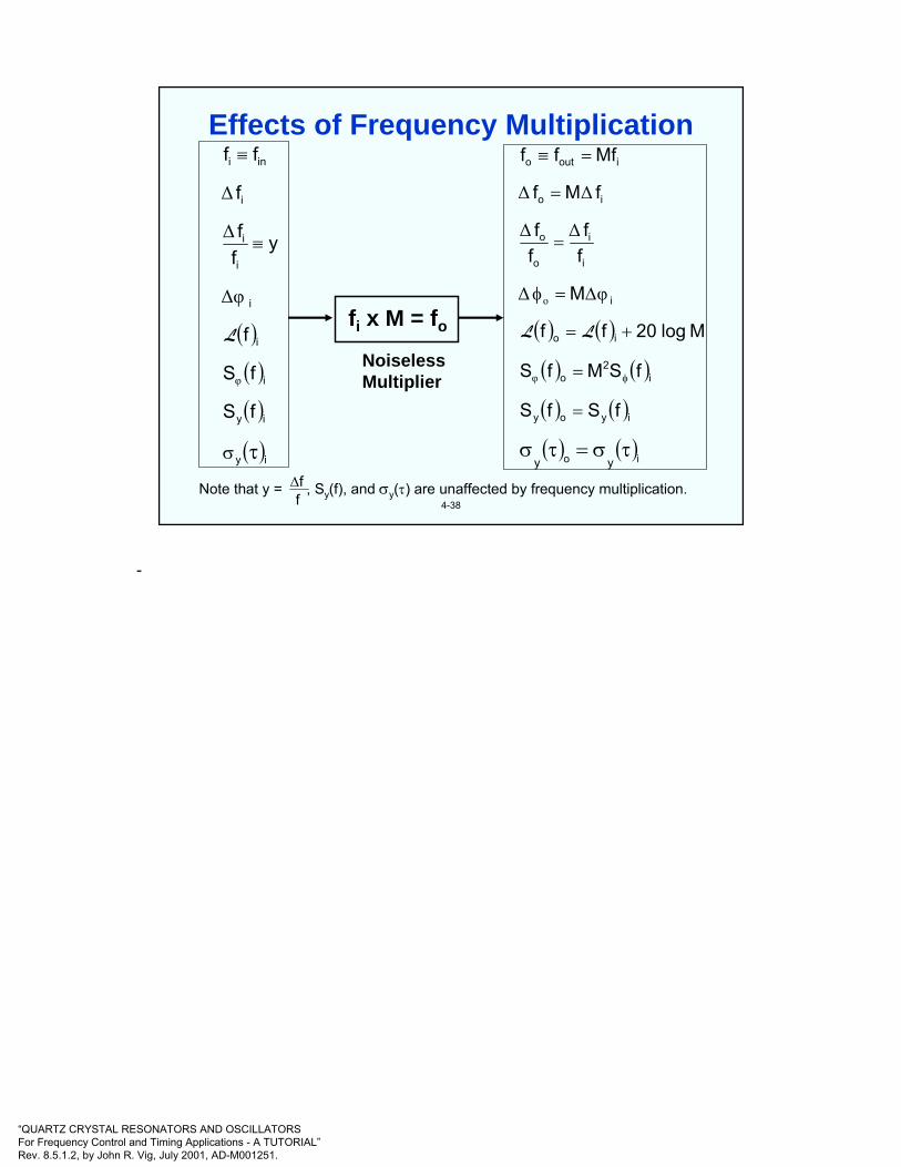
“QUARTZ CRYSTAL RESONATORS AND OSCILLATORSFor Frequency Control and Timing Applications - A TUTORIAL”Rev. 8.5.1.2, by John R. Vig, July 2001, AD-M001251.
4-38
fi x M = fo
Note that y = , Sy(f), and σy(τ) are unaffected by frequency multiplication.∆ff
NoiselessMultiplier
( )( )( )
( )iy
iy
i
i
i
i
i
i
ini
fS
fS
f
yff
f
ff
τσ
≡
≡
φ
∆φ
∆
∆
L ( ) ( )
( ) ( )
( ) ( )
( ) ( )io
iyoy
i2
o
io
i
i
i
o
o
io
iouto
yy
fSfS
fSMfS
Mlog20ff
M
ff
ff
fMf
Mfff
τσ=τσ
=
=
+=
∆=φ
=
=
=≡
φφ
o φ∆
∆∆
∆∆
LL
Effects of Frequency Multiplication
-

“QUARTZ CRYSTAL RESONATORS AND OSCILLATORSFor Frequency Control and Timing Applications - A TUTORIAL”Rev. 8.5.1.2, by John R. Vig, July 2001, AD-M001251.
4-39
The short term stabilities of TCXOs are temperature (T) dependent, and are generally worse than those of OCXOs, for the following reasons:
• The slope of the TCXO crystal’s frequency (f) vs. T varies with T. For example, the f vs. T slope may be near zero at ~20oC, but it will be ~1ppm/oC at the T extremes. T fluctuations will cause small f fluctuations at laboratory ambient T’s, so the stability can be good there, but millidegree fluctuations will cause ~10-9 f fluctuations at the T extremes. The TCXO’s f vs. T slopes also vary with T; the zeros and maxima can be at any T, and the maximum slopes can be on the order of 1 ppm/oC.
• AT-cut crystals’ thermal transient sensitivity makes the effects of T fluctuations depend not only on the T but also on the rate of change of T (whereas the SC-cut crystals typically used in precision OCXOs are insensitive to thermal transients). Under changing T conditions, the T gradient between the T sensor (thermistor) and the crystal will aggravate the problems.
• TCXOs typically use fundamental mode AT-cut crystals which have lower Q and larger C1 than the crystals typically used in OCXOs. The lower Q makes the crystals inherently noisier, and the larger C1 makes the oscillators more susceptible to circuitry noise.
• AT-cut crystals’ f vs. T often exhibit activity dips (see “Activity Dips” later in this chapter). At the T’s where the dips occur, the f vs. T slope can be very high, so the noise due to T fluctuations will also be very high, e.g., 100x degradation of σy(τ) and 30 dB degradation of phase noise are possible. Activity dips can occur at any T.
TCXO Noise
-

“QUARTZ CRYSTAL RESONATORS AND OSCILLATORSFor Frequency Control and Timing Applications - A TUTORIAL”Rev. 8.5.1.2, by John R. Vig, July 2001, AD-M001251.
4-40
Temperature coefficient of frequency = -0.035 ppm/0C2
Tim
e Er
ror p
er D
ay (s
econ
ds)
-550CMilitary“Cold”
-100CWinter
+280CWristTemp.
+490CDesert
+850CMilitary“Hot”
0
10
20
Quartz Wristwatch Accuracy vs. Temperature
The frequencies of crystal (as well as all other) oscillators are sensitive to temperature. Illustrated above is the effect for the oscillators used in quartz watches.
Quartz wristwatches are sufficiently accurate, usually, while worn as intended, i.e., on the wrist for ~16 h and off the wrist for ~8 h each day. The accuracies degrade when the watch is off the wrist for extended periods. The further the storage temperature is from the optimum temperature, the faster the watch loses time. At temperature extremes, e.g., in a freezer at - 55oC, or at the temperature of boiling water, wristwatches lose about 20 s per day.
The angle of cut of the resonator used in wristwatches is such that the zero temperature coefficient is at ~250C. This has been found to provide the highest probability of accuracy, based on the typical durations and temperatures while the watch is on the wrist and while it is off the wrist.

“QUARTZ CRYSTAL RESONATORS AND OSCILLATORSFor Frequency Control and Timing Applications - A TUTORIAL”Rev. 8.5.1.2, by John R. Vig, July 2001, AD-M001251.
4-41
Inflection Point
TemperatureLowerTurnover
Point (LTP)
UpperTurnover
Point (UTP)
f (UTP)
f (LTP)
Freq
uenc
y
Frequency vs. Temperature Characteristics
Shown above is the frequency vs. temperature (f vs. T) characteristic that is typical of e.g., AT-cut and SC-cut resonators. The upper and lower turnover points (UTP and LTP) are the points where the f vs. T has zero slope, i.e., df(T)/dT = 0. The corresponding frequencies are the upper and lower turnover frequencies, respectively.
The inflection point is where the curvature of the f vs. T changes from convex to concave, i.e., where d2f(T)/dT2 = 0. The inflection temperatures are ≈ 260C for AT-cuts, and ≈ 960C for SC-cuts.
The values of the inflection temperature, and the dependence of the f vs. T on the angles of cut depend not only on the angles of cut but also on the resonator’s design. For example, whereas a 3rd overtone SC-cut’s inflection temperature is ~96oC, a fundamental mode SC-cut’s is ~105oC.
“Quartz Resonator Handbook - Manufacturing Guide for AT-Type Units,” edited by R. E. Bennett, prepared for the US Dep’t of the Army, pp. 77-103, 1960, AD-274031.
J. A. Kusters, "The SC Cut Crystal - An Overview," Proc. 1981 IEEE Ultrasonics Symposium, pp. 402-409.

“QUARTZ CRYSTAL RESONATORS AND OSCILLATORSFor Frequency Control and Timing Applications - A TUTORIAL”Rev. 8.5.1.2, by John R. Vig, July 2001, AD-M001251.
4-42
Primary: Angles of cut
Secondary:• Overtone• Blank geometry (contour, dimensional ratios)• Material impurities and strains• Mounting & bonding stresses (magnitude and
direction)• Electrodes (size, shape, thickness, density, stress)• Drive level• Interfering modes• Load reactance (value & temperature coefficient)• Temperature rate of change• Thermal history• Ionizing radiation
Resonator f vs. T Determining Factors
See the next page for the f vs. T vs. angle-of-cut family of curves for the AT-cut (when all secondary effects are constant).

“QUARTZ CRYSTAL RESONATORS AND OSCILLATORSFor Frequency Control and Timing Applications - A TUTORIAL”Rev. 8.5.1.2, by John R. Vig, July 2001, AD-M001251.
4-43
rm
R
R
R
Rrm Y
ZAT-cut BT-cut49o35¼o
-1’
0’
1’
2’
3’
4’
5’
6’
7’
8’
-1’
0’
1’
2’
3’
4’
5’
6’
7’
8’
∆θ
Y-bar quartzZ
25
20
15
10
5
0
-5
-10
-15
-20
-25 -45 -40 -35 -30 -25 -20 -15 -10 -5 0 5 10 15 20 25 30 35 40 45 50 55 60 65 70 75 80 85 90
∆f f
(ppm
)
Temperature (oC)
θ = 35o 20’ + ∆θ, ϕ = 0for 5th overtone AT-cut
θ = 35o 12.5’+ ∆θ, ϕ = 0 forfundamental mode plano-plano AT-cut
Frequency-Temperature vs. Angle-of-Cut, AT-cut
The inset in the above illustration shows how an AT-cut plate and a BT-cut plate are related to the directions in a quartz bar. The illustration shows how the AT-cut’s f vs. T characteristics change as the θ angle of cut (see “Zero Temperature Coefficient Quartz Cuts” in chapter 3) is varied in one minute of arc increments.
The ∆θ = 0 curve shows the f vs. T characteristic at the “reference angle,” which is θ = 35o12.5’for a fundamental mode AT-cut resonator. At the reference angle, the turnover points coincide with the inflection point. The reference angle varies with design, i.e., with overtone, plate contour, etc.
“Quartz Resonator Handbook - Manufacturing Guide for AT-Type Units,” edited by R. E. Bennett, prepared for the US Dep’t of the Army, pp. 77-103, 1960, AD-274031.
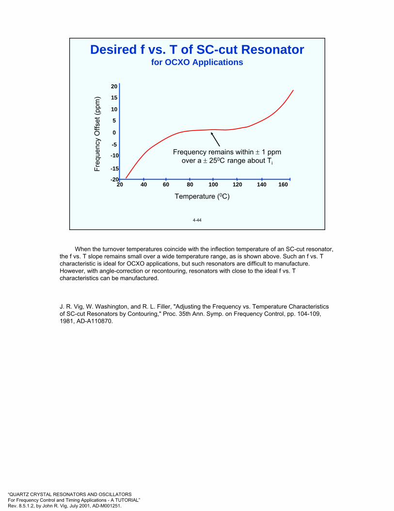
“QUARTZ CRYSTAL RESONATORS AND OSCILLATORSFor Frequency Control and Timing Applications - A TUTORIAL”Rev. 8.5.1.2, by John R. Vig, July 2001, AD-M001251.
4-44
Freq
uenc
y O
ffset
(ppm
)
Frequency remains within ± 1 ppmover a ± 250C range about Ti
Temperature (0C)
20
15
10
5
0
-5
-10
-15
-2020 40 60 80 100 120 140 160
Desired f vs. T of SC-cut Resonatorfor OCXO Applications
When the turnover temperatures coincide with the inflection temperature of an SC-cut resonator, the f vs. T slope remains small over a wide temperature range, as is shown above. Such an f vs. T characteristic is ideal for OCXO applications, but such resonators are difficult to manufacture. However, with angle-correction or recontouring, resonators with close to the ideal f vs. T characteristics can be manufactured.
J. R. Vig, W. Washington, and R. L. Filler, "Adjusting the Frequency vs. Temperature Characteristics of SC-cut Resonators by Contouring," Proc. 35th Ann. Symp. on Frequency Control, pp. 104-109, 1981, AD-A110870.
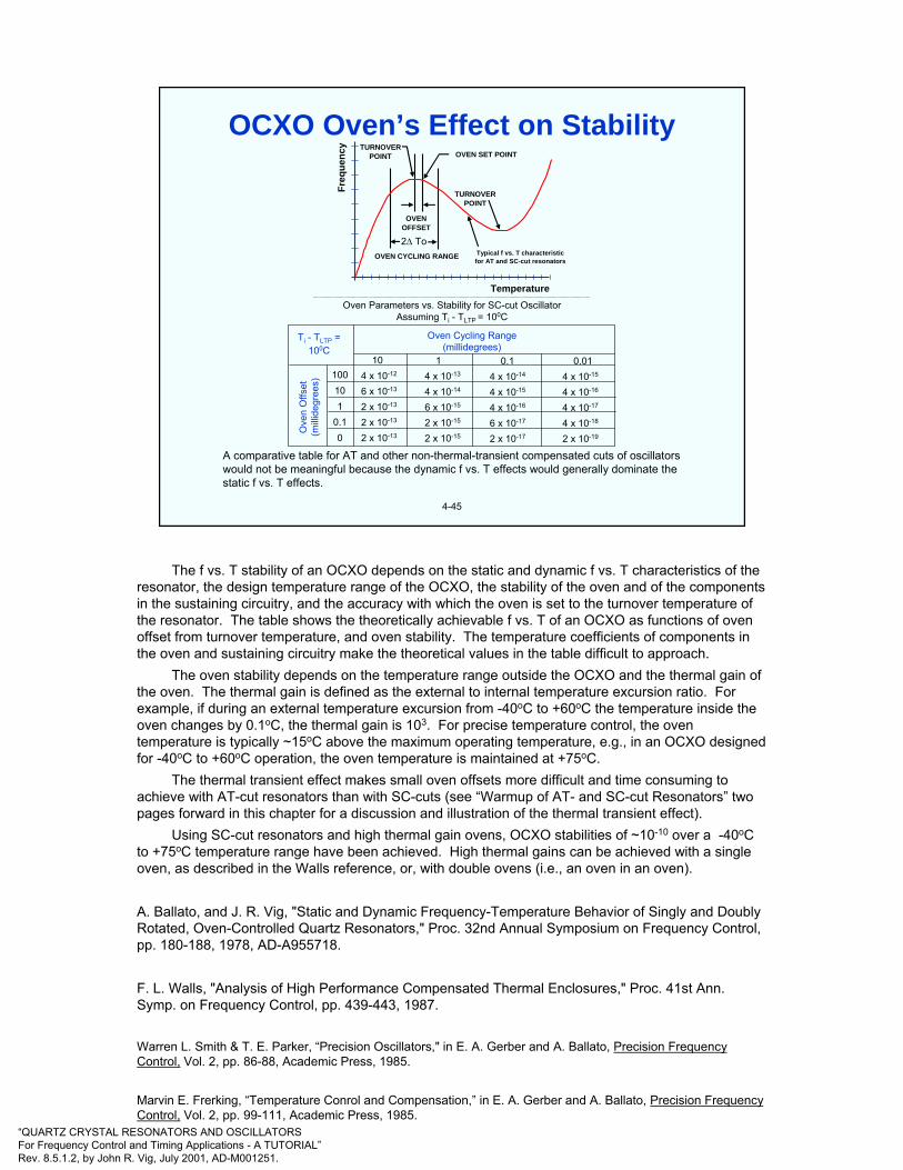
“QUARTZ CRYSTAL RESONATORS AND OSCILLATORSFor Frequency Control and Timing Applications - A TUTORIAL”Rev. 8.5.1.2, by John R. Vig, July 2001, AD-M001251.
4-45
A comparative table for AT and other non-thermal-transient compensated cuts of oscillators would not be meaningful because the dynamic f vs. T effects would generally dominate the static f vs. T effects.
Oven Parameters vs. Stability for SC-cut OscillatorAssuming Ti - TLTP = 100C
Ti - TLTP =100C
Ove
n O
ffset
(milli
degr
ees)
Oven Cycling Range(millidegrees)
104 x 10-12
6 x 10-13
2 x 10-13
2 x 10-13
2 x 10-13
14 x 10-13
4 x 10-14
6 x 10-15
2 x 10-15
2 x 10-15
0.14 x 10⁻¹⁴
4 x 10-15
4 x 10-16
6 x 10-17
2 x 10-17
0.014 x 10⁻¹⁵
4 x 10-16
4 x 10-17
4 x 10-18
2 x 10-19
100101
0.10
TURNOVERPOINT
OVEN SET POINTTURNOVER
POINT
OVENOFFSET
2∆ ToOVEN CYCLING RANGE Typical f vs. T characteristic
for AT and SC-cut resonators
Freq
uenc
y
Temperature
OCXO Oven’s Effect on Stability
The f vs. T stability of an OCXO depends on the static and dynamic f vs. T characteristics of the resonator, the design temperature range of the OCXO, the stability of the oven and of the components in the sustaining circuitry, and the accuracy with which the oven is set to the turnover temperature of the resonator. The table shows the theoretically achievable f vs. T of an OCXO as functions of oven offset from turnover temperature, and oven stability. The temperature coefficients of components in the oven and sustaining circuitry make the theoretical values in the table difficult to approach.
The oven stability depends on the temperature range outside the OCXO and the thermal gain of the oven. The thermal gain is defined as the external to internal temperature excursion ratio. For example, if during an external temperature excursion from -40oC to +60oC the temperature inside the oven changes by 0.1oC, the thermal gain is 103. For precise temperature control, the oven temperature is typically ~15oC above the maximum operating temperature, e.g., in an OCXO designed for -40oC to +60oC operation, the oven temperature is maintained at +75oC.
The thermal transient effect makes small oven offsets more difficult and time consuming to achieve with AT-cut resonators than with SC-cuts (see “Warmup of AT- and SC-cut Resonators” two pages forward in this chapter for a discussion and illustration of the thermal transient effect).
Using SC-cut resonators and high thermal gain ovens, OCXO stabilities of ~10-10 over a -40oC to +75oC temperature range have been achieved. High thermal gains can be achieved with a single oven, as described in the Walls reference, or, with double ovens (i.e., an oven in an oven).
A. Ballato, and J. R. Vig, "Static and Dynamic Frequency-Temperature Behavior of Singly and Doubly Rotated, Oven-Controlled Quartz Resonators," Proc. 32nd Annual Symposium on Frequency Control, pp. 180-188, 1978, AD-A955718.
F. L. Walls, "Analysis of High Performance Compensated Thermal Enclosures," Proc. 41st Ann. Symp. on Frequency Control, pp. 439-443, 1987.
Warren L. Smith & T. E. Parker, “Precision Oscillators," in E. A. Gerber and A. Ballato, Precision Frequency Control, Vol. 2, pp. 86-88, Academic Press, 1985.
Marvin E. Frerking, “Temperature Conrol and Compensation,” in E. A. Gerber and A. Ballato, Precision Frequency Control, Vol. 2, pp. 99-111, Academic Press, 1985.
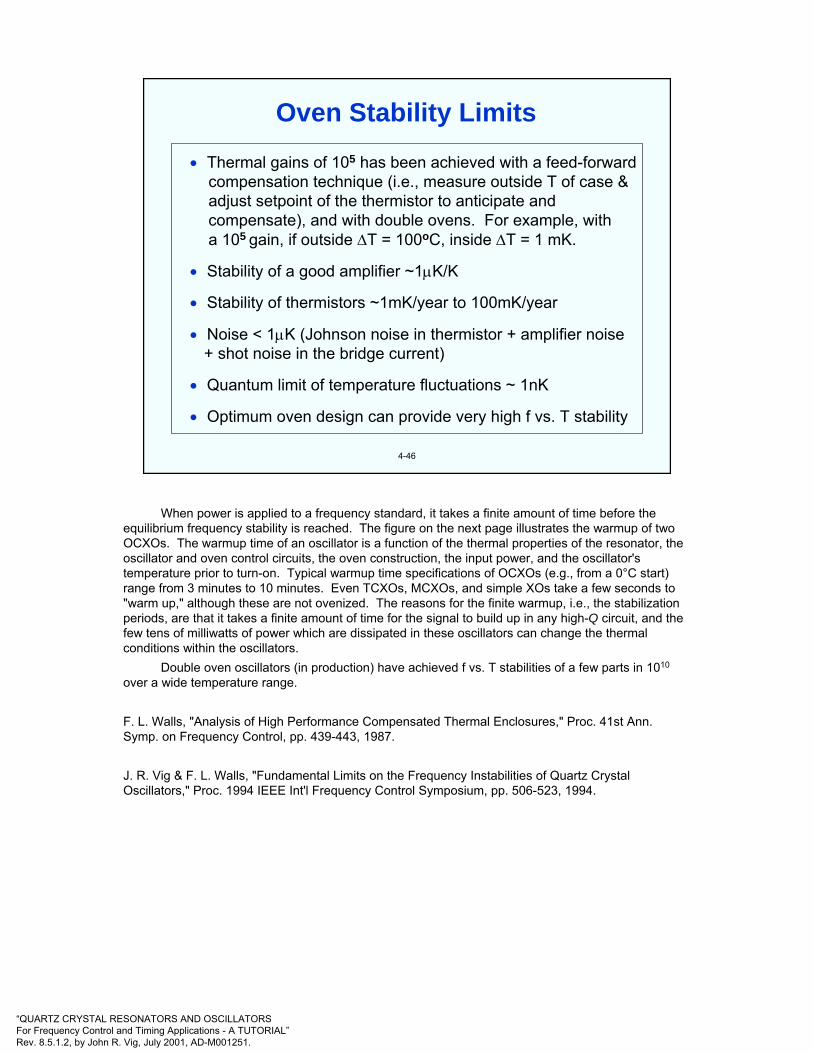
“QUARTZ CRYSTAL RESONATORS AND OSCILLATORSFor Frequency Control and Timing Applications - A TUTORIAL”Rev. 8.5.1.2, by John R. Vig, July 2001, AD-M001251.
4-46
• Thermal gains of 105 has been achieved with a feed-forwardcompensation technique (i.e., measure outside T of case &adjust setpoint of the thermistor to anticipate and compensate), and with double ovens. For example, witha 105 gain, if outside ∆T = 100oC, inside ∆T = 1 mK.
• Stability of a good amplifier ~1µK/K
• Stability of thermistors ~1mK/year to 100mK/year
• Noise < 1µK (Johnson noise in thermistor + amplifier noise + shot noise in the bridge current)
• Quantum limit of temperature fluctuations ~ 1nK
• Optimum oven design can provide very high f vs. T stability
Oven Stability Limits
When power is applied to a frequency standard, it takes a finite amount of time before the equilibrium frequency stability is reached. The figure on the next page illustrates the warmup of two OCXOs. The warmup time of an oscillator is a function of the thermal properties of the resonator, the oscillator and oven control circuits, the oven construction, the input power, and the oscillator's temperature prior to turn-on. Typical warmup time specifications of OCXOs (e.g., from a 0°C start) range from 3 minutes to 10 minutes. Even TCXOs, MCXOs, and simple XOs take a few seconds to "warm up," although these are not ovenized. The reasons for the finite warmup, i.e., the stabilization periods, are that it takes a finite amount of time for the signal to build up in any high-Q circuit, and the few tens of milliwatts of power which are dissipated in these oscillators can change the thermal conditions within the oscillators.
Double oven oscillators (in production) have achieved f vs. T stabilities of a few parts in 1010
over a wide temperature range.
F. L. Walls, "Analysis of High Performance Compensated Thermal Enclosures," Proc. 41st Ann. Symp. on Frequency Control, pp. 439-443, 1987.
J. R. Vig & F. L. Walls, "Fundamental Limits on the Frequency Instabilities of Quartz Crystal Oscillators," Proc. 1994 IEEE Int'l Frequency Control Symposium, pp. 506-523, 1994.

“QUARTZ CRYSTAL RESONATORS AND OSCILLATORSFor Frequency Control and Timing Applications - A TUTORIAL”Rev. 8.5.1.2, by John R. Vig, July 2001, AD-M001251.
4-47
Deviation from static f vs. t = ,
where, for example, ≈-2 x 10⁻⁷ s/K2
for a typical AT-cut resonator
dtdTa~
a~
Time (min)
Oven Warmup Time
Frac
tiona
l Fre
quen
cy D
evia
tion
From
Tur
nove
r Fre
quen
cy
3 6 9 12 15
10-3
10-4
10-5
-10-6
10-7
10-8
-10-8
-10-7
10-6
0
Warmup of AT- and SC-cut Resonators
Changing the temperature surrounding a crystal unit produces thermal gradients when, for example, heat flows to or from the active area of the resonator plate through the mounting clips. The static f vs. T characteristic is modified by the thermal-transient effect resulting from the thermal-gradient-induced stresses. When an OCXO is turned on, there can be a significant thermal-transient effect. The above figure shows what happens to the frequency output of two OCXOs, each containing an oven that reaches the equilibrium temperature in six minutes. One oven contains an AT-cut, the other, an SC-cut crystal. Thermal gradients in the AT-cut produce a large frequency undershoot that anneals out several minutes after the oven reaches equilibrium. The SC-cut crystal, being "stress-compensated" and thereby insensitive to such thermal-transient-induced stresses, reaches the equilibrium frequency as soon as the oven stabilizes.
In addition to extending the warmup time of OCXOs, when crystals other than SC-cuts are used, the thermal-transient effect makes it much more difficult to adjust the temperature of OCXO ovens to the desired turnover points, and the OCXO frequencies are much more sensitive to oven-temperature fluctuations.
The testing and compensation accuracies of TCXOs are also adversely affected by the thermal-transient effect. As the temperature is changed, the thermal-transient effect distorts the static f vs. Tcharacteristic, which leads to apparent hysteresis (see “Apparent Hysteresis” later in this chapter). The faster the temperature is changed, the larger is the contribution of the thermal-transient effect to the f vs. T performance.
A. Ballato, and J. R. Vig, "Static and Dynamic Frequency-Temperature Behavior of Singly and Doubly Rotated, Oven-Controlled Quartz Resonators," Proc. 32nd Annual Symposium on Frequency Control, pp. 180-188, 1978, AD-A955718.
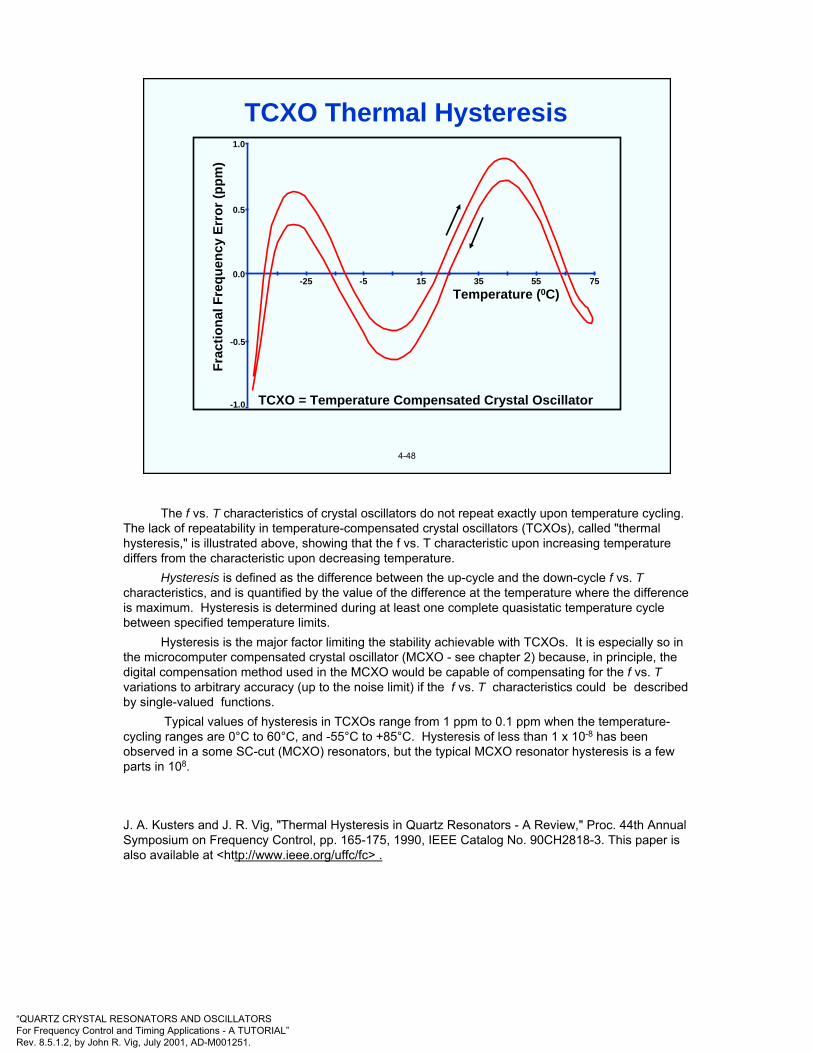
“QUARTZ CRYSTAL RESONATORS AND OSCILLATORSFor Frequency Control and Timing Applications - A TUTORIAL”Rev. 8.5.1.2, by John R. Vig, July 2001, AD-M001251.
4-48
Temperature (0C)
TCXO = Temperature Compensated Crystal Oscillator
Frac
tiona
l Fre
quen
cy E
rror
(ppm
)0.5
1.0
0.0
-0.5
-1.0
-25 -5 15 35 55 75
TCXO Thermal Hysteresis
The f vs. T characteristics of crystal oscillators do not repeat exactly upon temperature cycling. The lack of repeatability in temperature-compensated crystal oscillators (TCXOs), called "thermal hysteresis," is illustrated above, showing that the f vs. T characteristic upon increasing temperature differs from the characteristic upon decreasing temperature.
Hysteresis is defined as the difference between the up-cycle and the down-cycle f vs. Tcharacteristics, and is quantified by the value of the difference at the temperature where the difference is maximum. Hysteresis is determined during at least one complete quasistatic temperature cycle between specified temperature limits.
Hysteresis is the major factor limiting the stability achievable with TCXOs. It is especially so in the microcomputer compensated crystal oscillator (MCXO - see chapter 2) because, in principle, the digital compensation method used in the MCXO would be capable of compensating for the f vs. Tvariations to arbitrary accuracy (up to the noise limit) if the f vs. T characteristics could be described by single-valued functions.
Typical values of hysteresis in TCXOs range from 1 ppm to 0.1 ppm when the temperature-cycling ranges are 0°C to 60°C, and -55°C to +85°C. Hysteresis of less than 1 x 10⁻⁸ has been observed in a some SC-cut (MCXO) resonators, but the typical MCXO resonator hysteresis is a few parts in 108.
J. A. Kusters and J. R. Vig, "Thermal Hysteresis in Quartz Resonators - A Review," Proc. 44th Annual Symposium on Frequency Control, pp. 165-175, 1990, IEEE Catalog No. 90CH2818-3. This paper is also available at <http://www.ieee.org/uffc/fc> .

“QUARTZ CRYSTAL RESONATORS AND OSCILLATORSFor Frequency Control and Timing Applications - A TUTORIAL”Rev. 8.5.1.2, by John R. Vig, July 2001, AD-M001251.
4-49
Temperature (C)
-55
-45
-35
-25
-15 -5 5 15 25 35 45 55 65 75 85
45
40
35
30
25
20
15
10
5
0
Nor
mal
ized
freq
uenc
y ch
ange
(ppm
)
Apparent Hysteresis
Shown above is the -55oC to +85oC to -55oC frequency vs. temperature characteristic of an SC-cut resonator when the temperature was measured with a quartz thermometer external to the resonator. When, during the same temperature cycle, the temperature was measured by means of the self-temperature sensing method, no hysteresis could be detected when observed on the scale shown above (for a discussion of the self-temperature sensing method, see “Effects of Harmonics on f vs. T” later in this chapter, and “Resonator Self-Temperature Sensing” in chapter 2).
The apparent hysteresis shown above is due to the thermal lag between the resonator and thermometer during the temperature cycle (the rate of change of temperature was ~0.25oC/min). The left to right shift between the two curves is an indicator that one is observing apparent, rather than real hysteresis. Real hysteresis usually shifts the curves vertically, i.e., in real hysteresis, at the same temperature, there is a frequency difference between the two curves. In apparent hysteresis, the thermal gradients dominate the f vs. T results.
The apparent hysteresis would have been much greater if the resonator had been, e.g., an AT-cut, because of the thermal transient effect (see “Warmup of AT- and SC-cut Resonators,” earlier in this chapter).
R. L. Filler, “"Measurement and Analysis of Thermal Hysteresis in Resonators and TCXO's" Proc. 42nd Ann. Symp. On Frequency Control, pp. 380-388, 1988.
J. A. Kusters and J. R. Vig, "Thermal Hysteresis in Quartz Resonators - A Review," Proc. 44th Annual Symposium on Frequency Control, pp. 165-175, 1990, IEEE Catalog No. 90CH2818-3.
R. Filler and J. Vig, "Resonators for the Microcomputer-Compensated Crystal Oscillator," Proc. 43rd Annual Symposium on Frequency Control, pp. 8-15, 1989, IEEE Catalog No. 89CH2690-6.

“QUARTZ CRYSTAL RESONATORS AND OSCILLATORSFor Frequency Control and Timing Applications - A TUTORIAL”Rev. 8.5.1.2, by John R. Vig, July 2001, AD-M001251.
4-50
In (a), the oscillator was kept on continuously while the oven was cycledoff and on. In (b), the oven was kept on continuously while the oscillatorwas cycled off and on.
OVENOFF
(a)
14 days
14 days
OSCILLATOROFF
OSCILLATOR ON (b)
OVEN ON
∆f f
15
10
5
0
15
5
0
10X
10-9
OCXO Retrace
The lack of repeatability of the f vs. T characteristics of oven controlled crystal oscillators (OCXOs), called "retrace," is illustrated above. Retrace is defined as the nonrepeatability of the f vs. Tcharacteristic, usually at the oven temperature of an OCXO, upon on-off cycling under specified conditions. Retrace is a function of the storage temperature during the off period.
The OCXO retrace example above shows that upon restarting the oscillator after a 14 day off-period, the frequency was about 7x10⁻⁹ lower than what it was just before turn-off, and that the aging rate had increased significantly upon the restart. About a month elapsed before the pre-turn-off aging rate was reached again. (Figure shows ∆f/f in parts in 109 vs. time in days.)
Retrace limits the accuracies achievable with OCXOs in applications where the OCXO is on-off cycled. Typical OCXO retrace specifications, after a 24 hour off period at about 25°C, range from 2 x 10⁻⁸ to 1 x 10⁻⁹. Low-temperature storage during the off period, and extending the off period, often make the retrace worse.
The causes of hysteresis and retrace are not well understood. The experimental evidence to date is inconclusive. The mechanisms that can cause these effects include strain changes in the resonator’s mounting structure, changes in the quartz, oscillator circuitry changes, contamination redistribution in the crystal enclosure, and apparent hysteresis or retrace due to thermal gradients.
W. L. Smith, and W. J. Spencer, "Quartz Crystal Controlled Oscillators," Final Report, U.S. Army Contract DA36-039 SC-85373, Report No. 25335-H, 15 March 1963, AD-419717.
R. A. Sykes, W. L. Smith, and W. J. Spencer, "Studies on High Precision Resonators," Proc. 17th Annual Symposium on Frequency Control, pp. 4-27, 1963, AD423381. Proc. copies available from NTIS.
J. A. Kusters and J. R. Vig, "Thermal Hysteresis in Quartz Resonators - A Review," Proc. 44th Annual Symposium on Frequency Control, pp. 165-175, 1990, IEEE Catalog No. 90CH2818-3. This paper is also available at <http://www.ieee.org/uffc/fc>
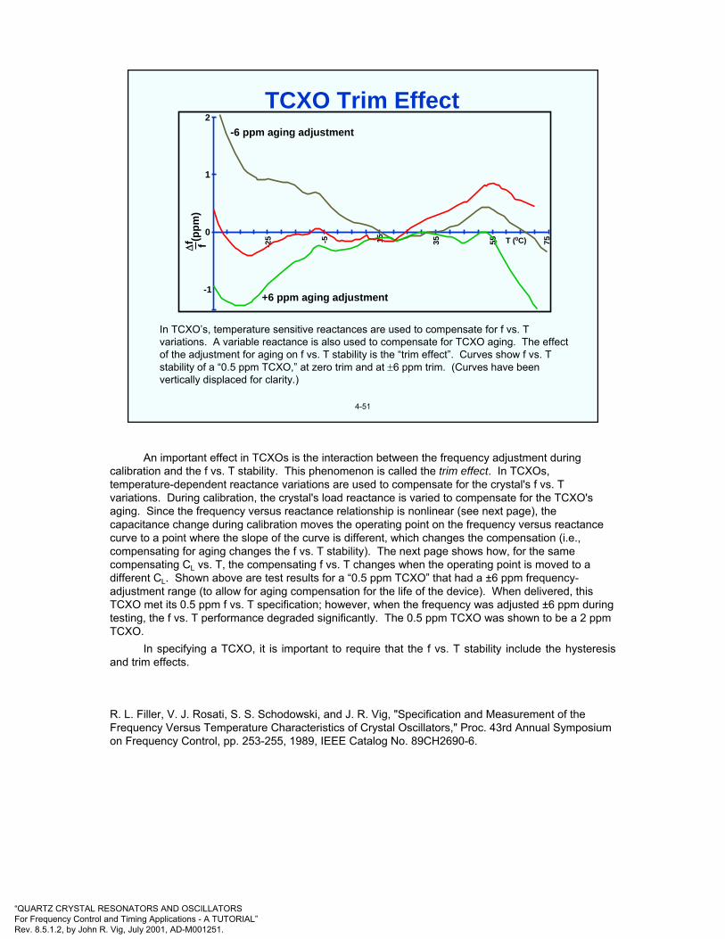
“QUARTZ CRYSTAL RESONATORS AND OSCILLATORSFor Frequency Control and Timing Applications - A TUTORIAL”Rev. 8.5.1.2, by John R. Vig, July 2001, AD-M001251.
4-51
In TCXO’s, temperature sensitive reactances are used to compensate for f vs. T variations. A variable reactance is also used to compensate for TCXO aging. The effect of the adjustment for aging on f vs. T stability is the “trim effect”. Curves show f vs. T stability of a “0.5 ppm TCXO,” at zero trim and at ±6 ppm trim. (Curves have been vertically displaced for clarity.)
2
1
0
-1
∆f f(p
pm)
-25 -5 15 35 55 75
-6 ppm aging adjustment
+6 ppm aging adjustment
T (0C)
TCXO Trim Effect
An important effect in TCXOs is the interaction between the frequency adjustment during calibration and the f vs. T stability. This phenomenon is called the trim effect. In TCXOs, temperature-dependent reactance variations are used to compensate for the crystal's f vs. T variations. During calibration, the crystal's load reactance is varied to compensate for the TCXO's aging. Since the frequency versus reactance relationship is nonlinear (see next page), the capacitance change during calibration moves the operating point on the frequency versus reactance curve to a point where the slope of the curve is different, which changes the compensation (i.e., compensating for aging changes the f vs. T stability). The next page shows how, for the same compensating CL vs. T, the compensating f vs. T changes when the operating point is moved to a different CL. Shown above are test results for a “0.5 ppm TCXO” that had a ±6 ppm frequency-adjustment range (to allow for aging compensation for the life of the device). When delivered, this TCXO met its 0.5 ppm f vs. T specification; however, when the frequency was adjusted ±6 ppm during testing, the f vs. T performance degraded significantly. The 0.5 ppm TCXO was shown to be a 2 ppmTCXO.
In specifying a TCXO, it is important to require that the f vs. T stability include the hysteresis and trim effects.
R. L. Filler, V. J. Rosati, S. S. Schodowski, and J. R. Vig, "Specification and Measurement of the Frequency Versus Temperature Characteristics of Crystal Oscillators," Proc. 43rd Annual Symposium on Frequency Control, pp. 253-255, 1989, IEEE Catalog No. 89CH2690-6.

“QUARTZ CRYSTAL RESONATORS AND OSCILLATORSFor Frequency Control and Timing Applications - A TUTORIAL”Rev. 8.5.1.2, by John R. Vig, July 2001, AD-M001251.
4-52
CL
Compensated f vs. T
Compensating CL vs. T
( )L0
1
S CC2C
ff
+≈
∆
Sff∆
Why the Trim Effect?
The same variation of Cl with T causes a different f vs. T compensation when the value of CL is changed.

“QUARTZ CRYSTAL RESONATORS AND OSCILLATORSFor Frequency Control and Timing Applications - A TUTORIAL”Rev. 8.5.1.2, by John R. Vig, July 2001, AD-M001251.
4-53
T DEGREES CELSIUS
SC-cut
r = Co/C1 = 746α = 0.130
ff∆
12
8
4
0
-4
-8
-12-50 200 450 700 950 1200 1450 1700 1950
* 10-6
Effects of Load Capacitance on f vs. T
A load capacitor, CL, changes not only the frequency (see chapter 3), but also the frequency vs. temperature characteristic. Shown above are the f vs. T characteristics of the same resonator with and without a CL. The CL rotates the f vs. T curve as if the angle of cut had been lowered (because the combined effect of the resonator and CL lowers the effect of piezoelectricity, as explained in the reference below). So, the CL raises the frequency at all temperatures (the curve with fL has been vertically displaced for clarity), and it also rotates the f vs. T to a lower apparent angle of cut, i.e., it reduces the turning-point-to-turning-point frequencies and temperatures.
The temperature coefficient of CL can greatly amplify the f vs. T rotation.
A. Ballato, "Frequency-Temperature-Load Capacitance Behavior of Resonators for TCXO Application," IEEE Trans. Sonics Ultrasonics., SU-25, pp.185-191, July 1978.
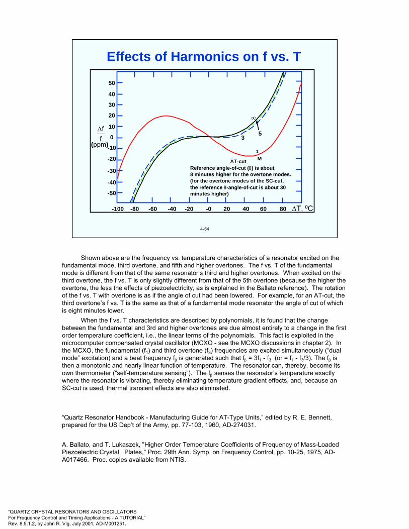
“QUARTZ CRYSTAL RESONATORS AND OSCILLATORSFor Frequency Control and Timing Applications - A TUTORIAL”Rev. 8.5.1.2, by John R. Vig, July 2001, AD-M001251.
4-54
(ppm)5
3
M
∆T, 0C
50
40
30
20
10
0
-10
-20
-30
-50
-100 -80 -40 -20 -0 20 40 60 80
AT-cutReference angle-of-cut (θ) is about8 minutes higher for the overtone modes.(for the overtone modes of the SC-cut,the reference θ-angle-of-cut is about 30minutes higher)
1
-60
-40
∞
ff∆
Effects of Harmonics on f vs. T
Shown above are the frequency vs. temperature characteristics of a resonator excited on the fundamental mode, third overtone, and fifth and higher overtones. The f vs. T of the fundamental mode is different from that of the same resonator’s third and higher overtones. When excited on the third overtone, the f vs. T is only slightly different from that of the 5th overtone (because the higher the overtone, the less the effects of piezoelectricity, as is explained in the Ballato reference). The rotation of the f vs. T with overtone is as if the angle of cut had been lowered. For example, for an AT-cut, the third overtone’s f vs. T is the same as that of a fundamental mode resonator the angle of cut of which is eight minutes lower.
When the f vs. T characteristics are described by polynomials, it is found that the change between the fundamental and 3rd and higher overtones are due almost entirely to a change in the first order temperature coefficient, i.e., the linear terms of the polynomials. This fact is exploited in the microcomputer compensated crystal oscillator (MCXO - see the MCXO discussions in chapter 2). In the MCXO, the fundamental (f1) and third overtone (f3) frequencies are excited simultaneously (“dual mode” excitation) and a beat frequency fβ is generated such that fβ = 3f1 - f3 (or = f1 - f3/3). The fβ is then a monotonic and nearly linear function of temperature. The resonator can, thereby, become its own thermometer (“self-temperature sensing”). The fβ senses the resonator’s temperature exactly where the resonator is vibrating, thereby eliminating temperature gradient effects, and, because an SC-cut is used, thermal transient effects are also eliminated.
“Quartz Resonator Handbook - Manufacturing Guide for AT-Type Units,” edited by R. E. Bennett, prepared for the US Dep’t of the Army, pp. 77-103, 1960, AD-274031.
A. Ballato, and T. Lukaszek, "Higher Order Temperature Coefficients of Frequency of Mass-Loaded Piezoelectric Crystal Plates," Proc. 29th Ann. Symp. on Frequency Control, pp. 10-25, 1975, AD-A017466. Proc. copies available from NTIS.

“QUARTZ CRYSTAL RESONATORS AND OSCILLATORSFor Frequency Control and Timing Applications - A TUTORIAL”Rev. 8.5.1.2, by John R. Vig, July 2001, AD-M001251.
4-55
At high drive levels, resonance curves become asymmetric due to the nonlinearities of quartz.
Nor
mal
ized
cur
rent
am
plitu
de
Frequency10 -6
10 µ W 100 µ W 400 µ W 4000 µ W
Amplitude - Frequency Effect
When the frequency is swept through resonance, as the driving voltage is increased, the resonance curve bends over due to the nonlinear constants of quartz. The peak of each curve is the resonance frequency. The AT-cut, illustrated above, bends towards higher frequencies, i.e., it behaves as a hard spring (a hard spring’s stiffness increases with increasing displacement). Some other cuts behave as soft springs; the resonance curve bends towards lower frequencies. The locus of the maxima of the resonance curves varies as the square of the current, ∆f/f = aI2, where a is typically in the range of 0.02/A2 to 0.2/A2; a depends on resonator design - angles of cut, overtone, plate contour, etc.
At high drive levels, the amplitude vs. frequency curves can be triple valued functions, but only the highest and lowest values are accessible experimentally (upon increasing and decreasing voltages, respectively). The current vs. frequency exhibits discontinuities as the driving voltage (or frequency) is increased or decreased around the resonance peak.
D. Hammond, C. Adams, and L. Cutler, "Precision Crystal Units," Proc. 17th Annual Symposium on Frequency Control, pp. 215-232, 1963, AD-423381.
R. L. Filler, "The Amplitude-Frequency Effect in SC-Cut Resonators," Proc. 39th Annual Symposium on Frequency Control, pp. 311-316, 1985, IEEE Catalog No. 85CH2186-5.
H. F. Tiersten and D. S. Stevens, “The Evaluationof the Coefficients of Nonlinear Resonance for SC-cut Quartz Resonators,” Proc. 39th Annual Symposium on Frequency Control, pp. 325-332, 1985, IEEE Catalog No. 85CH2186-5.
J.J. Gagnepain and R. Besson, “Nonlinear Effects in Piezoelectric Quartz Crystals,” in Physical Acoustics, Vol. XI, pp. 245-288, W.P. Mason & R.N. Thurston, editors, Academic Press, 1975

“QUARTZ CRYSTAL RESONATORS AND OSCILLATORSFor Frequency Control and Timing Applications - A TUTORIAL”Rev. 8.5.1.2, by John R. Vig, July 2001, AD-M001251.
4-56
Freq
uenc
y C
hang
e (p
arts
in 1
09)
80
60
40
20
0
-20
100 200 300 400 500 600 700
5 MHz AT
3 diopter10 MHz SC
2 diopter10 MHz SC
1 diopter10 MHz SC
10 MHz BT
Crystal Current (microamperes)
Frequency vs. Drive Level
Frequency varies as the current amplitude squared; f = f0 (1 + aI2), where a is a constant that is a function of the design, i.e., the appropriate nonlinear elastic constant for the resonator type used, and I is the current.
Useful drive levels are limited at the high end by the nonlinearities of quartz, and at the low end by noise (or defects, as discussed on the next page).
J. A. Kusters, "The SC Cut Crystal - An Overview," Proc. 1981 IEEE Ultrasonics Symposium, pp. 402-409.
J.J. Gagnepain and R. Besson, “Nonlinear Effects in Piezoelectric Quartz Crystals,” in Physical Acoustics, Vol. XI, pp. 245-288, W.P. Mason & R.N. Thurston, editors, Academic Press, 1975
R. L. Filler, "The Amplitude-Frequency Effect in SC-Cut Resonators," Proc. 39th Annual Symposium on Frequency Control, pp. 311-316, 1985, IEEE Catalog No. 85CH2186-5.
D. Hammond, C. Adams, and L. Cutler, "Precision Crystal Units," Proc. 17th Annual Symposium on Frequency Control, pp. 215-232, 1963, AD-423381.

“QUARTZ CRYSTAL RESONATORS AND OSCILLATORSFor Frequency Control and Timing Applications - A TUTORIAL”Rev. 8.5.1.2, by John R. Vig, July 2001, AD-M001251.
4-57
10-3 10-2 10-1 1 10 100
Res
ista
nce
R1
IX (mA)
Anomalousstartingresistance
Normaloperatingrange
Drive leveleffects
Drive Level vs. Resistance
The high resistance at low drive currents, and the “second level of drive” effect shown on the next page, are troublesome because they can appear and cause failure well after the resonator has passed the final manufacturing tests. The effect can prevent oscillator start-up when the oscillator circuit’s gain is insufficient. In some resonators, the effect can be “cured” by applying a high drive level, however, such cures are often not permanent. The effect can reappear long after the high drive level was applied. (Increasing the drive level increases the amplitude of vibration at the resonator’s surface, which can remove surface contamination. However, when the high drive is applied to a hermetically sealed resonator, the contamination stays within the enclosure and can redeposit at a later time.)
Removing loose particles and other surface contaminants during processing, before the resonator is sealed into its enclosure, e.g., by properly etching and cleaning the resonators, can significantly reduce the incidence of this effect. Imperfections in the electrodes, such as scratches, blisters and irregular adhesion can also produce the effect.
Properly made resonators show no resistance increase at low drive levels - down to at least 10-
5 amperes of drive current*.------------------------------* R. Smythe, Piezo Technology, Inc., private communication, April 1999.M. Bernstein, “Increased Crystal Unit Resistance at Oscillator Noise Levels,” Proc. 21st Annual Symposium on Frequency Control, pp. 244-258, 1967. J. E. Knowles, "On the Origin of the 'Second Level of Drive' Effect in Quartz Oscillators," Proc. 29th Annual Symposium on Frequency Control, pp. 230-236, 1975, AD-A017466. E. P. EerNisse, “An Analysis of the Drive Level Sensitivity in Thickness Shear Quartz Resonators,”Proc. 1996 Int’l Frequency Control Symposium, pp. 346-356, 1996, IEEE Cat. No. 96CH35935.E.P EerNisse, E. Benes, M. Schmid, “The Role of Localized Rotational Imbalance in Drive Level Dependence Phenomena,” Pro. 2002 IEEE Int’l Frequency Control Symp., pp. 2-7, 2002.

“QUARTZ CRYSTAL RESONATORS AND OSCILLATORSFor Frequency Control and Timing Applications - A TUTORIAL”Rev. 8.5.1.2, by John R. Vig, July 2001, AD-M001251.
4-58
O A
B
C
D Drive level (voltage)
Act
ivity
(cur
rent
)
Second Level of Drive Effect
A “good” crystal will follow the path OABCBAO without hysteresis. A “bad” crystal will follow the path OADBCBAO: hence the term “second level of drive”. Upon increasing the drive again, there is a tendency for the magnitude of the effect to decrease, but in a very irregular and irreproducible manner. The effect is usually due to particulate contamination, loose electrodes, or other surface defects.
M. Bernstein, “Increased Crystal Unit Resistance at Oscillator Noise Levels,” Proc. 21st Annual Symposium on Frequency Control, pp. 244-258, 1967.
J. E. Knowles, "On the Origin of the 'Second Level of Drive' Effect in Quartz Oscillators," Proc. 29th Annual Symposium on Frequency Control, pp. 230-236, 1975, AD-A017466.
E. P. EerNisse, “An Analysis of the Drive Level Sensitivity in Thickness Shear Quartz Resonators,”Proc. 1996 Int’l Frequency Control Symposium, pp. 346-356, 1996, IEEE Cat. No. 96CH35935
E.P EerNisse, E. Benes, M. Schmid, “The Role of Localized Rotational Imbalance in Drive Level Dependence Phenomena,” Pro. 2002 IEEE Int’l Frequency Control Symp., pp. 2-7, 2002.

“QUARTZ CRYSTAL RESONATORS AND OSCILLATORSFor Frequency Control and Timing Applications - A TUTORIAL”Rev. 8.5.1.2, by John R. Vig, July 2001, AD-M001251.
4-59
Activity dips in the f vs. T and R vs. T when operated with and without load capacitors. Dip temperatures are a function of CL, which indicates that the dip is caused by a mode (probably flexure) with a large negative temperature coefficient.
Freq
uenc
yR
esis
tanc
e
Temperature (0C)-40 -20 0 20 40 60 80 100
RL2RL1
R1
fL1
fL2
fR
10 X10-6
ff∆
Activity Dips
Anomalies in the f vs. T and R vs. T characteristics, as illustrated above, are called “activity dips”. The curves labeled fR and R1 are the f vs. T and R vs. T without a load capacitor. The fL and RLcurves are the f vs. T and R vs. T of the same resonator when load capacitors are in series with the resonator. The load capacitors shift the frequency to higher values; the curves have been vertically displaced for clarity.
An activity dip can cause intermittent failures. It affects both the frequency and the resistance (i.e., the Q) of resonators. When the oscillator gain is insufficient, the resistance increase stops the oscillation. For example, the clock in one satellite stopped periodically a certain time interval after the satellite entered the earth’s shadow. As the satellite cooled, the oscillator’s temperature reached the activity dip temperature and the oscillation stopped. Upon further temperature change, the oscillation resumed.
Even when the resistance increase is not large enough to stop the oscillation, the frequency change can cause intermittent failures, e.g., it can cause a loss of lock in phase locked systems.
Activity dips are usually caused by interfering modes (e.g., by high overtone flexure modes). Such activity dips are strongly influenced by the crystal's drive level and load reactance. The activity-dip temperature is a function of CL because the interfering mode’s frequency usually has a large temperature coefficient and a C1 that is different from that of the desired mode. When the frequency of the interfering mode coincides with the frequency of the main mode, energy is lost from the main mode and an activity dip occurs.
Activity dip like features can also be caused by processing problems, e.g., loose contacts. Such dips usually change with temperature cycling, rather than with load capacitance. --------------------------------A. Ballato and R. Tilton, "Electronic Activity Dip Measurement," IEEE Trans. on Instrumentation and Measurement, Vol. IM-27, No. 1, pp. 59-65, March 1978; also “Ovenless Activity Dip Tester,” in Proc. 31st Ann. Symp. On Frequency Control, pp. 102-107, 1977.See also “Overtone Response…” & “Unwanted Modes vs. Temperature” in Chapter 3.
E.P EerNisse, E. Benes, M. Schmid, “The Role of Localized Rotational Imbalance in Drive Level Dependence Phenomena,” Pro. 2002 IEEE Int’l Frequency Control Symp., pp. 2-7, 2002.
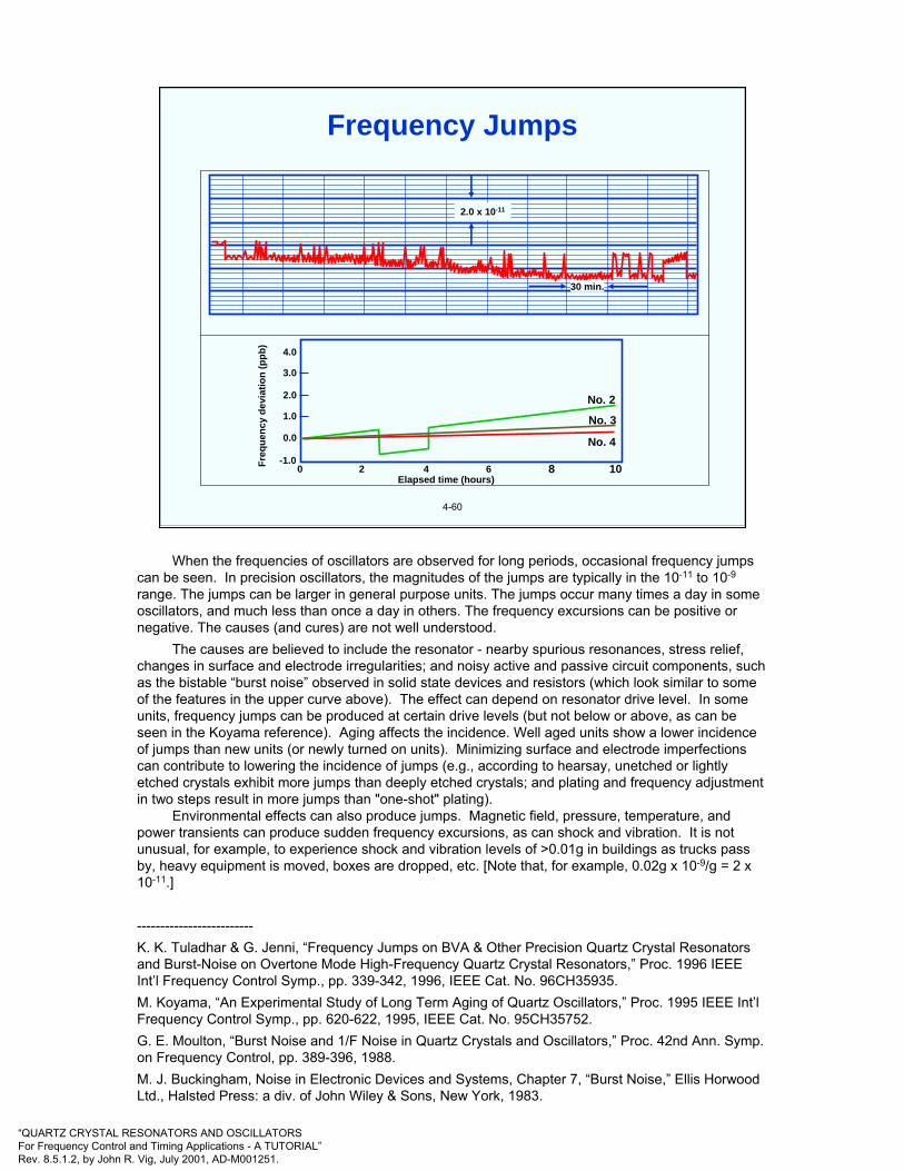
“QUARTZ CRYSTAL RESONATORS AND OSCILLATORSFor Frequency Control and Timing Applications - A TUTORIAL”Rev. 8.5.1.2, by John R. Vig, July 2001, AD-M001251.
4-60
4.0
3.0
2.0
1.0
0.0
-1.00 2 4 6 8 10
No. 2
No. 3
No. 4
Freq
uenc
y de
viat
ion
(ppb
)
Elapsed time (hours)
2.0 x 10⁻¹¹
30 min.
Frequency Jumps
When the frequencies of oscillators are observed for long periods, occasional frequency jumps can be seen. In precision oscillators, the magnitudes of the jumps are typically in the 10-11 to 10-9
range. The jumps can be larger in general purpose units. The jumps occur many times a day in some oscillators, and much less than once a day in others. The frequency excursions can be positive or negative. The causes (and cures) are not well understood.
The causes are believed to include the resonator - nearby spurious resonances, stress relief, changes in surface and electrode irregularities; and noisy active and passive circuit components, such as the bistable “burst noise” observed in solid state devices and resistors (which look similar to some of the features in the upper curve above). The effect can depend on resonator drive level. In some units, frequency jumps can be produced at certain drive levels (but not below or above, as can be seen in the Koyama reference). Aging affects the incidence. Well aged units show a lower incidence of jumps than new units (or newly turned on units). Minimizing surface and electrode imperfections can contribute to lowering the incidence of jumps (e.g., according to hearsay, unetched or lightly etched crystals exhibit more jumps than deeply etched crystals; and plating and frequency adjustment in two steps result in more jumps than "one-shot" plating).
Environmental effects can also produce jumps. Magnetic field, pressure, temperature, and power transients can produce sudden frequency excursions, as can shock and vibration. It is not unusual, for example, to experience shock and vibration levels of >0.01g in buildings as trucks pass by, heavy equipment is moved, boxes are dropped, etc. [Note that, for example, 0.02g x 10-9/g = 2 x 10-11.]
-------------------------K. K. Tuladhar & G. Jenni, “Frequency Jumps on BVA & Other Precision Quartz Crystal Resonators and Burst-Noise on Overtone Mode High-Frequency Quartz Crystal Resonators,” Proc. 1996 IEEE Int’l Frequency Control Symp., pp. 339-342, 1996, IEEE Cat. No. 96CH35935.M. Koyama, “An Experimental Study of Long Term Aging of Quartz Oscillators,” Proc. 1995 IEEE Int’l Frequency Control Symp., pp. 620-622, 1995, IEEE Cat. No. 95CH35752.G. E. Moulton, “Burst Noise and 1/F Noise in Quartz Crystals and Oscillators,” Proc. 42nd Ann. Symp. on Frequency Control, pp. 389-396, 1988.M. J. Buckingham, Noise in Electronic Devices and Systems, Chapter 7, “Burst Noise,” Ellis HorwoodLtd., Halsted Press: a div. of John Wiley & Sons, New York, 1983.

“QUARTZ CRYSTAL RESONATORS AND OSCILLATORSFor Frequency Control and Timing Applications - A TUTORIAL”Rev. 8.5.1.2, by John R. Vig, July 2001, AD-M001251.
4-61
• Acceleration Force Deformation (strain) Change in material and device properties - to some level
• Examples: - Quartz resonator frequency- Amplifier gain (strain changes semiconductor band structure)- Laser diode emission frequencies- Optical properties - fiber index of refraction (acoustooptics)- Cavity frequencies- DRO frequency (strain changes dielectric constants)- Atomic clock frequencies- Stray reactances- Clock rates (relativistic effects)
Acceleration Affects “Everything”
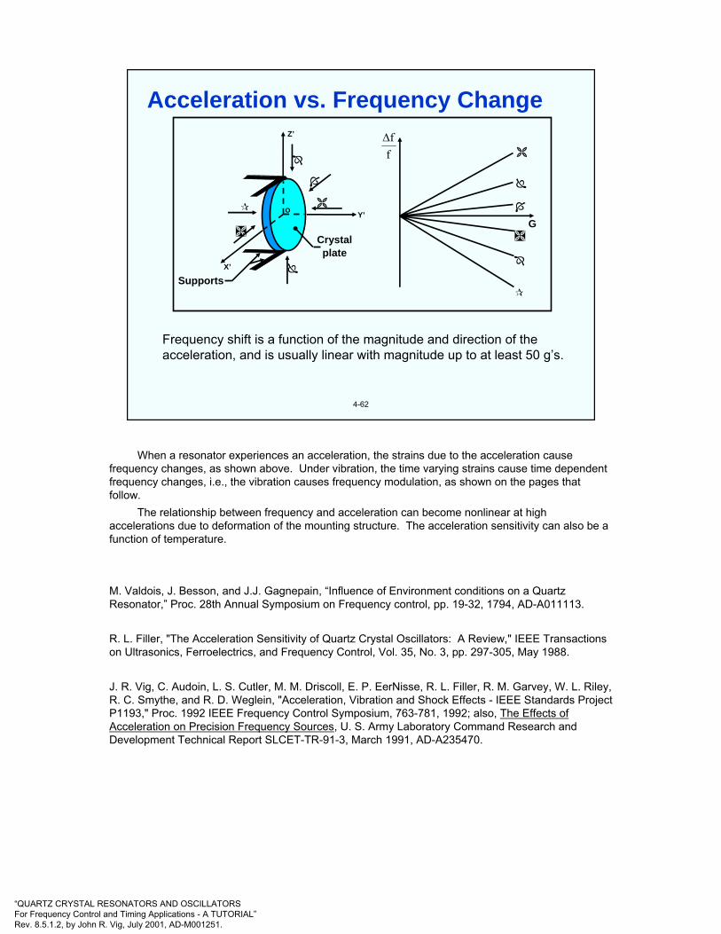
“QUARTZ CRYSTAL RESONATORS AND OSCILLATORSFor Frequency Control and Timing Applications - A TUTORIAL”Rev. 8.5.1.2, by John R. Vig, July 2001, AD-M001251.
4-62
Frequency shift is a function of the magnitude and direction of the acceleration, and is usually linear with magnitude up to at least 50 g’s.
Crystalplate
Supports
ff∆
X’
Y’
Z’
GO
Acceleration vs. Frequency Change
When a resonator experiences an acceleration, the strains due to the acceleration cause frequency changes, as shown above. Under vibration, the time varying strains cause time dependent frequency changes, i.e., the vibration causes frequency modulation, as shown on the pages that follow.
The relationship between frequency and acceleration can become nonlinear at high accelerations due to deformation of the mounting structure. The acceleration sensitivity can also be a function of temperature.
M. Valdois, J. Besson, and J.J. Gagnepain, “Influence of Environment conditions on a Quartz Resonator,” Proc. 28th Annual Symposium on Frequency control, pp. 19-32, 1794, AD-A011113.
R. L. Filler, "The Acceleration Sensitivity of Quartz Crystal Oscillators: A Review," IEEE Transactions on Ultrasonics, Ferroelectrics, and Frequency Control, Vol. 35, No. 3, pp. 297-305, May 1988.
J. R. Vig, C. Audoin, L. S. Cutler, M. M. Driscoll, E. P. EerNisse, R. L. Filler, R. M. Garvey, W. L. Riley, R. C. Smythe, and R. D. Weglein, "Acceleration, Vibration and Shock Effects - IEEE Standards Project P1193," Proc. 1992 IEEE Frequency Control Symposium, 763-781, 1992; also, The Effects of Acceleration on Precision Frequency Sources, U. S. Army Laboratory Command Research and Development Technical Report SLCET-TR-91-3, March 1991, AD-A235470.

“QUARTZ CRYSTAL RESONATORS AND OSCILLATORSFor Frequency Control and Timing Applications - A TUTORIAL”Rev. 8.5.1.2, by John R. Vig, July 2001, AD-M001251.
4-63
Axis 3
Axis 2
Axis 1
g
10.000 MHz oscillator’s tipover test
(f(max) - f(min))/2 = 1.889x10-09 (ccw)(f(max) - f(min))/2 = 1.863x10-09 (cw)delta θ = 106.0 deg.
(f(max) - f(min))/2 = 6.841x10⁻¹⁰ (ccw)(f(max) - f(min))/2 = 6.896x10⁻¹⁰ (cw)delta θ = 150.0 deg.
(f(max) - f(min))/2 = 1.882x10-09 (ccw)(f(max) - f(min))/2 = 1.859x10-09 (cw)delta θ = 16.0 deg.
910Xff −∆
Axis 1
Axis 2
4
-2
-4
2
0
45 90 135
180
225
270
315
360
2
0
45 90 135
180
225
270
315
360
2
0
45 90 135
180
225
270
315
360
4
-2
-4
-2
-4
4
2-g Tipover Test(∆f vs. attitude about three axes)
When an oscillator is rotated 1800 about a horizontal axis, the scalar product of the gravitational field and the unit vector normal to the initial “top” of the oscillator changes from -1g to +1g, i.e., by 2g. A simple “2g tipover” test is sometimes used to test an oscillator’s acceleration sensitivity. Above is actual data of the fractional frequency shifts of an oscillator when the oscillator was rotated about three mutually perpendicular axes in the earth’s gravitational field. For each curve, the axis of rotation was horizontal. The sinusoidal shape of each curve is a consequence of the scalar product being proportional to the cosine of the angle between the acceleration-sensitivity vector (see later) and the acceleration due to gravity.
The 2g tipover test must not be used indiscriminately because many oscillators exhibit irregular variations of frequency with attitude when tested in small increments of angle rather than with just simple 180o rotations. Irregularities can be caused by, for example, temperature changes due to air convection in the oscillator, and tiny movements of components, circuit boards and wires. When the frequency vs. attitude behavior is nonsinusoidal, the results of a simple 2g tipover test can be highly misleading.--------------------------
R. L. Filler, "The Acceleration Sensitivity of Quartz Crystal Oscillators: A Review," IEEE Transactions on Ultrasonics, Ferroelectrics, and Frequency Control, Vol. 35, No. 3, pp. 297-305, May 1988.
J. R. Vig, C. Audoin, L. S. Cutler, M. M. Driscoll, E. P. EerNisse, R. L. Filler, R. M. Garvey, W. L. Riley, R. C. Smythe, and R. D. Weglein, "Acceleration, Vibration and Shock Effects - IEEE Standards Project P1193," Proc. 1992 IEEE Frequency Control Symposium, 763-781, 1992; also, The Effects of Acceleration on Precision Frequency Sources, U. S. Army Laboratory Command Research and Development Technical Report SLCET-TR-91-3, March 1991, AD-A235470.
IEEE Standard 1193-1994, “IEEE Guide for Measurement of Environmental Sensitivities of Standard Frequency Generators”.

“QUARTZ CRYSTAL RESONATORS AND OSCILLATORSFor Frequency Control and Timing Applications - A TUTORIAL”Rev. 8.5.1.2, by John R. Vig, July 2001, AD-M001251.
4-64
Tim
e f0 - ∆f f0 + ∆f
f0 - ∆f f0 + ∆f
f0 - ∆f f0 + ∆f
f0 - ∆f f0 + ∆f
f0 - ∆f f0 + ∆f A
ccel
erat
ion
Time
Time
Volta
ge
0t =
v2ft π
=
vft π
=
v2f3t π
=
vf2t π
=
Sinusoidal Vibration Modulated Frequency
The above illustration shows how a time varying stress due to a time varying (sinusoidal) acceleration changes the frequency of a resonator, i.e., how the vibration frequency modulates the oscillator’s frequency.
R. L. Filler, "The Acceleration Sensitivity of Quartz Crystal Oscillators: A Review," IEEE Transactions on Ultrasonics, Ferroelectrics, and Frequency Control, Vol. 35, No. 3, pp. 297-305, May 1988.
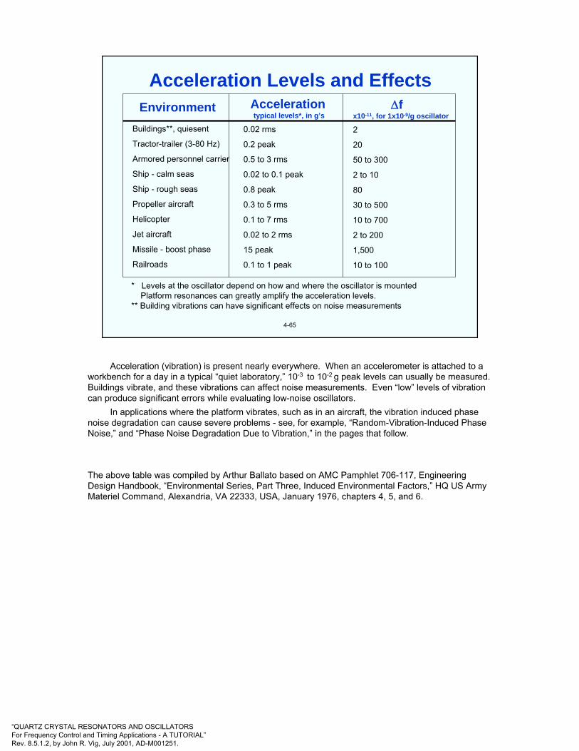
“QUARTZ CRYSTAL RESONATORS AND OSCILLATORSFor Frequency Control and Timing Applications - A TUTORIAL”Rev. 8.5.1.2, by John R. Vig, July 2001, AD-M001251.
4-65
EnvironmentBuildings**, quiesent
Tractor-trailer (3-80 Hz)
Armored personnel carrier
Ship - calm seas
Ship - rough seas
Propeller aircraft
Helicopter
Jet aircraft
Missile - boost phase
Railroads
Accelerationtypical levels*, in g’s
0.02 rms
0.2 peak
0.5 to 3 rms
0.02 to 0.1 peak
0.8 peak
0.3 to 5 rms
0.1 to 7 rms
0.02 to 2 rms
15 peak
0.1 to 1 peak
∆fx10-11, for 1x10⁻⁹/g oscillator
2
20
50 to 300
2 to 10
80
30 to 500
10 to 700
2 to 200
1,500
10 to 100
* Levels at the oscillator depend on how and where the oscillator is mountedPlatform resonances can greatly amplify the acceleration levels.
** Building vibrations can have significant effects on noise measurements
Acceleration Levels and Effects
Acceleration (vibration) is present nearly everywhere. When an accelerometer is attached to a workbench for a day in a typical “quiet laboratory,” 10-3 to 10-2 g peak levels can usually be measured. Buildings vibrate, and these vibrations can affect noise measurements. Even “low” levels of vibration can produce significant errors while evaluating low-noise oscillators.
In applications where the platform vibrates, such as in an aircraft, the vibration induced phase noise degradation can cause severe problems - see, for example, “Random-Vibration-Induced Phase Noise,” and “Phase Noise Degradation Due to Vibration,” in the pages that follow.
The above table was compiled by Arthur Ballato based on AMC Pamphlet 706-117, Engineering Design Handbook, “Environmental Series, Part Three, Induced Environmental Factors,” HQ US Army Materiel Command, Alexandria, VA 22333, USA, January 1976, chapters 4, 5, and 6.
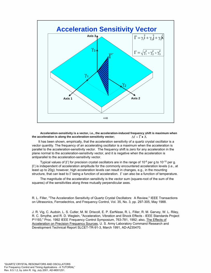
“QUARTZ CRYSTAL RESONATORS AND OSCILLATORSFor Frequency Control and Timing Applications - A TUTORIAL”Rev. 8.5.1.2, by John R. Vig, July 2001, AD-M001251.
4-66
Axis 1 Axis 2
Axis 3
γ1
γ2
γ3
Γ23
22
21
321 kji
γγγ=Γ
γ+γ+γ=Γ
++
Acceleration Sensitivity Vector
Acceleration-sensitivity is a vector, i.e., the acceleration-induced frequency shift is maximum when the acceleration is along the acceleration-sensitivity vector;
It has been shown, empirically, that the acceleration sensitivity of a quartz crystal oscillator is a vector quantity. The frequency of an accelerating oscillator is a maximum when the acceleration is parallel to the acceleration-sensitivity vector. The frequency shift is zero for any acceleration in the plane normal to the acceleration-sensitivity vector, and it is negative when the acceleration is antiparallel to the acceleration-sensitivity vector.
Typical values of |Γ| for precision crystal oscillators are in the range of 10-9 per g to 10-10 per g. |Γ| is independent of acceleration amplitude for the commonly encountered acceleration levels (i.e., at least up to 20g); however, high acceleration levels can result in changes, e.g., in the mounting structure, that can lead to Γ being a function of acceleration. Γ can also be a function of temperature.
The magnitude of the acceleration sensitivity is the vector sum (square-root of the sum of the squares) of the sensitivities along three mutually perpendicular axes.
R. L. Filler, "The Acceleration Sensitivity of Quartz Crystal Oscillators: A Review," IEEE Transactions on Ultrasonics, Ferroelectrics, and Frequency Control, Vol. 35, No. 3, pp. 297-305, May 1988.
J. R. Vig, C. Audoin, L. S. Cutler, M. M. Driscoll, E. P. EerNisse, R. L. Filler, R. M. Garvey, W. L. Riley, R. C. Smythe, and R. D. Weglein, "Acceleration, Vibration and Shock Effects - IEEE Standards Project P1193," Proc. 1992 IEEE Frequency Control Symposium, 763-781, 1992; also, The Effects of Acceleration on Precision Frequency Sources, U. S. Army Laboratory Command Research and Development Technical Report SLCET-TR-91-3, March 1991, AD-A235470.
Α•Γ=∆f

“QUARTZ CRYSTAL RESONATORS AND OSCILLATORSFor Frequency Control and Timing Applications - A TUTORIAL”Rev. 8.5.1.2, by John R. Vig, July 2001, AD-M001251.
4-67
Example shown: fv = 20, Hz A = 1.0 g along Γ, Γ = 1 x 10⁻⁹/g
0.001 0.01 0.1 1
10-9
10-10
10-11
10-12
( )secτ
( )τντ
πττ
γ+
−=σ
A1210y
( )τ
τ−
=σ1210
y
( )τσy
Vibration-Induced Allan Deviation Degradation
Vibration modulates the frequency and, thereby, degrades the short-term stability. The typical degradation due to sinusoidal vibration varies with averaging time, as shown. Since a full sine wave averages to zero, the degradation is zero for averaging times that are integer multiples of the period of vibration. The peaks occur at averaging times that are odd multiples of half the period of vibration. The σy(τ) due to a single-frequency vibration is:
σy (τ) = (Γ•A/π)(τv/τ) sin2 [π(τ/τv)], where τv is the period of vibration, τ is the measurement averaging time, Γ is the acceleration sensitivity vector, and A is the acceleration.
J. R. Vig, C. Audoin, L. S. Cutler, M. M. Driscoll, E. P. EerNisse, R. L. Filler, R. M. Garvey, W. L. Riley, R. C. Smythe, and R. D. Weglein, "Acceleration, Vibration and Shock Effects - IEEE Standards Project P1193," Proc. 1992 IEEE Frequency Control Symposium, 763-781, 1992; also, The Effects of Acceleration on Precision Frequency Sources, U. S. Army Laboratory Command Research and Development Technical Report SLCET-TR-91-3, March 1991, AD-A235470.

“QUARTZ CRYSTAL RESONATORS AND OSCILLATORSFor Frequency Control and Timing Applications - A TUTORIAL”Rev. 8.5.1.2, by John R. Vig, July 2001, AD-M001251.
4-68
The phase of a vibration modulated signal is
When the oscillator is subjected to a sinusoidal vibration, the peakphase excursion is
Example: if a 10 MHz, 1 x 10⁻⁹/g oscillator is subjected to a 10 Hzsinusoidal vibration of amplitude 1g, the peak vibration-induced phaseexcursion is 1 x 10⁻³ radian. If this oscillator is used as the referenceoscillator in a 10 GHz radar system, the peak phase excursion at 10GHzwill be 1 radian. Such a large phase excursion can be catastrophic tothe performance of many systems, such as those which employ phaselocked loops (PLL) or phase shift keying (PSK).
( ) ( )tf2sinfftf2tφ v
v0 π⎟⎟
⎠
⎞⎜⎜⎝
⎛+π=
∆
( )v
0
vpeak f
fAffφ •
==Γ∆∆
Vibration-Induced Phase Excursion
J. R. Vig, C. Audoin, L. S. Cutler, M. M. Driscoll, E. P. EerNisse, R. L. Filler, R. M. Garvey, W. L. Riley, R. C. Smythe, and R. D. Weglein, "Acceleration, Vibration and Shock Effects - IEEE Standards Project P1193," Proc. 1992 IEEE Frequency Control Symposium, 763-781, 1992; also, The Effects of Acceleration on Precision Frequency Sources, U. S. Army Laboratory Command Research and Development Technical Report SLCET-TR-91-3, March 1991, AD-A235470.

“QUARTZ CRYSTAL RESONATORS AND OSCILLATORSFor Frequency Control and Timing Applications - A TUTORIAL”Rev. 8.5.1.2, by John R. Vig, July 2001, AD-M001251.
4-69
L(f)
10g amplitude @ 100 HzΓ = 1.4 x 10⁻⁹ per g
0
-10
-20
-30
-40
-50
-60
-70
-80
-90
-100
-250
-200
-150
-100 -50 0 50 100
150
200
250f
NOTE: the “sidebands” are spectrallines at ±fV from the carrier frequency(where fV = vibration frequency). Thelines are broadened because of the finitebandwidth of the spectrum analyzer.
Vibration-Induced Sidebands
As shown in the references, for small modulation index β, i.e., β ≡ ∆f/fv = (Γ•A)fo/fv<0.1, sinusoidal vibration produces spectral lines at ± fv from the carrier, where fv is the vibration frequency. For an ideal sine wave, the “sidebands” are spectral lines (i.e., delta functions) not spectral densities. Most of the power is in the carrier, a small amount is in the first spectral line pair, and the higher order spectral lines are negligible. On a spectrum analyzer, the spectral lines appear to be sidebands - due to the finite bandwidth of the spectrum analyzer.
R. L. Filler, "The Acceleration Sensitivity of Quartz Crystal Oscillators: A Review," IEEE Transactions on Ultrasonics, Ferroelectrics, and Frequency Control, Vol. 35, No. 3, pp. 297-305, May 1988.
J. R. Vig, C. Audoin, L. S. Cutler, M. M. Driscoll, E. P. EerNisse, R. L. Filler, R. M. Garvey, W. L. Riley, R. C. Smythe, and R. D. Weglein, "Acceleration, Vibration and Shock Effects - IEEE Standards Project P1193," Proc. 1992 IEEE Frequency Control Symposium, 763-781, 1992; also, The Effects of Acceleration on Precision Frequency Sources, U. S. Army Laboratory Command Research and Development Technical Report SLCET-TR-91-3, March 1991, AD-A235470.
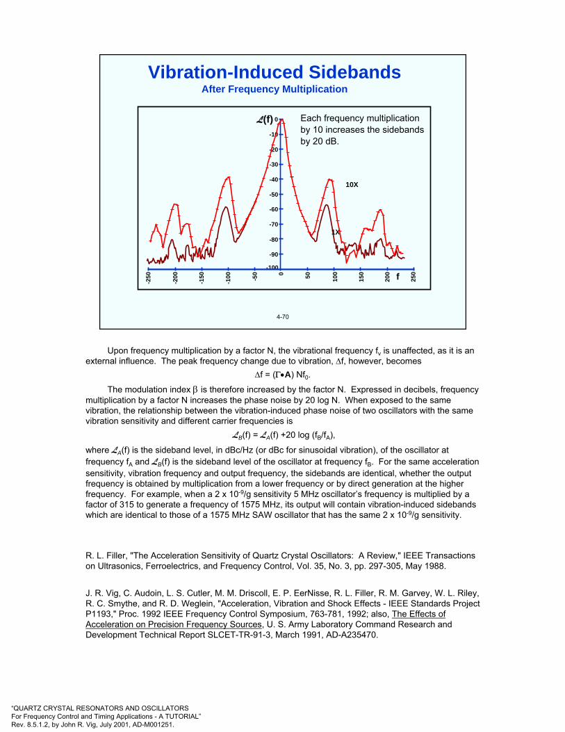
“QUARTZ CRYSTAL RESONATORS AND OSCILLATORSFor Frequency Control and Timing Applications - A TUTORIAL”Rev. 8.5.1.2, by John R. Vig, July 2001, AD-M001251.
Upon frequency multiplication by a factor N, the vibrational frequency fv is unaffected, as it is an external influence. The peak frequency change due to vibration, ∆f, however, becomes
∆f = (Γ•A) Nf0.
The modulation index β is therefore increased by the factor N. Expressed in decibels, frequency multiplication by a factor N increases the phase noise by 20 log N. When exposed to the same vibration, the relationship between the vibration-induced phase noise of two oscillators with the same vibration sensitivity and different carrier frequencies is
LB(f) = LA(f) +20 log (fB/fA),
where LA(f) is the sideband level, in dBc/Hz (or dBc for sinusoidal vibration), of the oscillator at frequency fA and LB(f) is the sideband level of the oscillator at frequency fB. For the same acceleration sensitivity, vibration frequency and output frequency, the sidebands are identical, whether the output frequency is obtained by multiplication from a lower frequency or by direct generation at the higher frequency. For example, when a 2 x 10⁻⁹/g sensitivity 5 MHz oscillator’s frequency is multiplied by a factor of 315 to generate a frequency of 1575 MHz, its output will contain vibration-induced sidebands which are identical to those of a 1575 MHz SAW oscillator that has the same 2 x 10⁻⁹/g sensitivity.
R. L. Filler, "The Acceleration Sensitivity of Quartz Crystal Oscillators: A Review," IEEE Transactions on Ultrasonics, Ferroelectrics, and Frequency Control, Vol. 35, No. 3, pp. 297-305, May 1988.
J. R. Vig, C. Audoin, L. S. Cutler, M. M. Driscoll, E. P. EerNisse, R. L. Filler, R. M. Garvey, W. L. Riley, R. C. Smythe, and R. D. Weglein, "Acceleration, Vibration and Shock Effects - IEEE Standards Project P1193," Proc. 1992 IEEE Frequency Control Symposium, 763-781, 1992; also, The Effects of Acceleration on Precision Frequency Sources, U. S. Army Laboratory Command Research and Development Technical Report SLCET-TR-91-3, March 1991, AD-A235470.
4-70
0
-10
-20
-30
-40
-50
-60
-70
-80
-90
-100
-250
-200
-150
-100 -50 0 50 100
150
200
250f
L(f) Each frequency multiplicationby 10 increases the sidebandsby 20 dB.
10X
1X
Vibration-Induced SidebandsAfter Frequency Multiplication
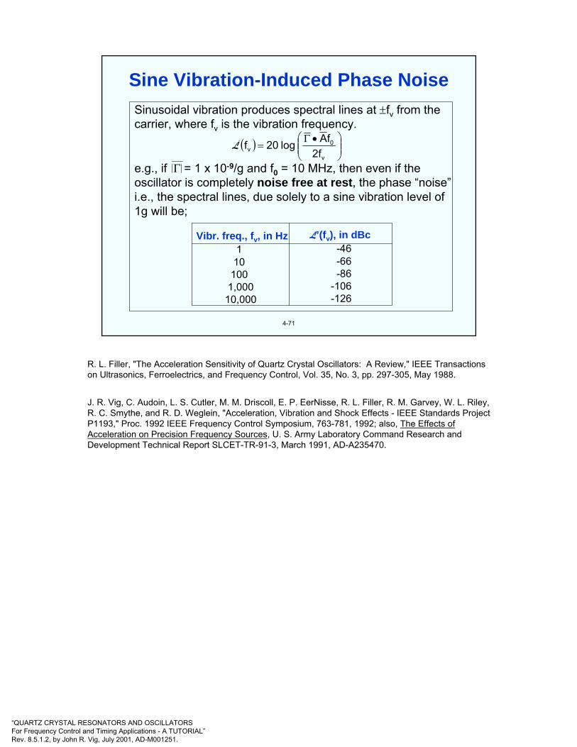
“QUARTZ CRYSTAL RESONATORS AND OSCILLATORSFor Frequency Control and Timing Applications - A TUTORIAL”Rev. 8.5.1.2, by John R. Vig, July 2001, AD-M001251.
4-71
Sinusoidal vibration produces spectral lines at ±fv from the carrier, where fv is the vibration frequency.
e.g., if Γ = 1 x 10⁻⁹/g and f0 = 10 MHz, then even if theoscillator is completely noise free at rest, the phase “noise”i.e., the spectral lines, due solely to a sine vibration level of 1g will be;
Vibr. freq., fv, in Hz1
101001,000
10,000
-46-66-86
-106-126
L’(fv), in dBc
( ) ⎟⎟⎠
⎞⎜⎜⎝
⎛ •Γ=
v
0v f2
fAlog20f'L
Sine Vibration-Induced Phase Noise
R. L. Filler, "The Acceleration Sensitivity of Quartz Crystal Oscillators: A Review," IEEE Transactions on Ultrasonics, Ferroelectrics, and Frequency Control, Vol. 35, No. 3, pp. 297-305, May 1988.
J. R. Vig, C. Audoin, L. S. Cutler, M. M. Driscoll, E. P. EerNisse, R. L. Filler, R. M. Garvey, W. L. Riley, R. C. Smythe, and R. D. Weglein, "Acceleration, Vibration and Shock Effects - IEEE Standards Project P1193," Proc. 1992 IEEE Frequency Control Symposium, 763-781, 1992; also, The Effects of Acceleration on Precision Frequency Sources, U. S. Army Laboratory Command Research and Development Technical Report SLCET-TR-91-3, March 1991, AD-A235470.

“QUARTZ CRYSTAL RESONATORS AND OSCILLATORSFor Frequency Control and Timing Applications - A TUTORIAL”Rev. 8.5.1.2, by John R. Vig, July 2001, AD-M001251.
4-72
Random vibration’s contribution to phase noise is given by:
e.g., if Γ = 1 x 10⁻⁹/g and f0 = 10 MHz, then even if theoscillator is completely noise free at rest, the phase “noise”i.e., the spectral lines, due solely to a vibration of power spectral density, PSD = 0.1 g2/Hz will be:
Offset freq., f, in Hz1
101001,000
10,000
L’(f), in dBc/Hz-53-73-93
-113-133
( ) ( )( )[ ] 210 PSD2lAlwhere,
f2fAlog20f =⎟⎟
⎠
⎞⎜⎜⎝
⎛ •Γ=L
Random Vibration-Induced Phase Noise
R. L. Filler, "The Acceleration Sensitivity of Quartz Crystal Oscillators: A Review," IEEE Transactions on Ultrasonics, Ferroelectrics, and Frequency Control, Vol. 35, No. 3, pp. 297-305, May 1988.
J. R. Vig, C. Audoin, L. S. Cutler, M. M. Driscoll, E. P. EerNisse, R. L. Filler, R. M. Garvey, W. L. Riley, R. C. Smythe, and R. D. Weglein, "Acceleration, Vibration and Shock Effects - IEEE Standards Project P1193," Proc. 1992 IEEE Frequency Control Symposium, 763-781, 1992; also, The Effects of Acceleration on Precision Frequency Sources, U. S. Army Laboratory Command Research and Development Technical Report SLCET-TR-91-3, March 1991, AD-A235470.
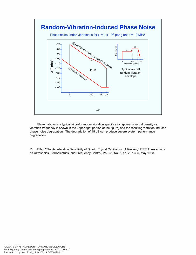
“QUARTZ CRYSTAL RESONATORS AND OSCILLATORSFor Frequency Control and Timing Applications - A TUTORIAL”Rev. 8.5.1.2, by John R. Vig, July 2001, AD-M001251.
4-73
-70
-80
-90
-100
-110
-120
-130
-140
-150
-160
L (f)
(dB
c)
1K 2K3005
45 dBL(f) without vibration
L(f) under the random vibration shown
5 300 1K 2K
PSD
(g2 /H
z)
.04
.07
Frequency (Hz)
Typical aircraftrandom vibration
envelope
Phase noise under vibration is for Γ = 1 x 10⁻⁹ per g and f = 10 MHz
Random-Vibration-Induced Phase Noise
Shown above is a typical aircraft random vibration specification (power spectral density vs. vibration frequency is shown in the upper right portion of the figure) and the resulting vibration-induced phase noise degradation. The degradation of 45 dB can produce severe system performance degradation.
R. L. Filler, "The Acceleration Sensitivity of Quartz Crystal Oscillators: A Review," IEEE Transactions on Ultrasonics, Ferroelectrics, and Frequency Control, Vol. 35, No. 3, pp. 297-305, May 1988.
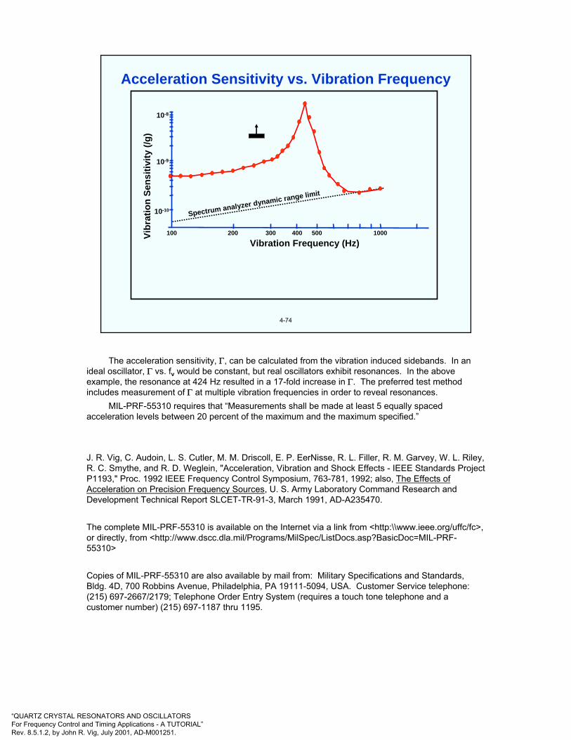
“QUARTZ CRYSTAL RESONATORS AND OSCILLATORSFor Frequency Control and Timing Applications - A TUTORIAL”Rev. 8.5.1.2, by John R. Vig, July 2001, AD-M001251.
4-74
Spectrum analyzer dynamic range limit
Vibr
atio
n Se
nsiti
vity
(/g)
10-8
10-9
10-10
100 200 300 400 500 1000
Vibration Frequency (Hz)
Acceleration Sensitivity vs. Vibration Frequency
The acceleration sensitivity, Γ, can be calculated from the vibration induced sidebands. In anideal oscillator, Γ vs. fv would be constant, but real oscillators exhibit resonances. In the above example, the resonance at 424 Hz resulted in a 17-fold increase in Γ. The preferred test method includes measurement of Γ at multiple vibration frequencies in order to reveal resonances.
MIL-PRF-55310 requires that “Measurements shall be made at least 5 equally spaced acceleration levels between 20 percent of the maximum and the maximum specified.”
J. R. Vig, C. Audoin, L. S. Cutler, M. M. Driscoll, E. P. EerNisse, R. L. Filler, R. M. Garvey, W. L. Riley, R. C. Smythe, and R. D. Weglein, "Acceleration, Vibration and Shock Effects - IEEE Standards Project P1193," Proc. 1992 IEEE Frequency Control Symposium, 763-781, 1992; also, The Effects of Acceleration on Precision Frequency Sources, U. S. Army Laboratory Command Research and Development Technical Report SLCET-TR-91-3, March 1991, AD-A235470.
The complete MIL-PRF-55310 is available on the Internet via a link from <http:\\www.ieee.org/uffc/fc>, or directly, from <http://www.dscc.dla.mil/Programs/MilSpec/ListDocs.asp?BasicDoc=MIL-PRF-55310>
Copies of MIL-PRF-55310 are also available by mail from: Military Specifications and Standards, Bldg. 4D, 700 Robbins Avenue, Philadelphia, PA 19111-5094, USA. Customer Service telephone: (215) 697-2667/2179; Telephone Order Entry System (requires a touch tone telephone and a customer number) (215) 697-1187 thru 1195.

“QUARTZ CRYSTAL RESONATORS AND OSCILLATORSFor Frequency Control and Timing Applications - A TUTORIAL”Rev. 8.5.1.2, by John R. Vig, July 2001, AD-M001251.
4-75
Resonator acceleration sensitivities range from the low parts in 1010 per g for the best commercially available SC-cuts, to parts in 107 per g for tuning-fork-type watch crystals. When a wide range of resonators were examined: AT, BT, FC, IT, SC, AK, and GT-cuts; 5 MHz 5th overtones to 500 MHz fundamental mode inverted mesa resonators; resonators made of natural quartz, cultured quartz, and swept cultured quartz; numerous geometries and mounting configurations (including rectangular AT-cuts); nearly all of the results were within a factor of three of 1x10⁻⁹
per g. On the other hand, the fact that a few resonators have been found to have sensitivities of less than 1x10⁻¹⁰ per g indicates that the observed acceleration sensitivities are not due to any inherent natural limitations.
Theoretical and experimental evidence indicates that the major variables yet to be controlled properly are the mode shape and location (i.e., the amplitude of vibration distribution), and the strain distribution associated with the mode of vibration. Theoretically, when the mounting is completely symmetrical with respect to the mode shape, the acceleration sensitivity can be zero, but tiny changes from this ideal condition can cause a significant sensitivity. Until the acceleration sensitivity problem is solved, acceleration compensation and vibration isolation can provide lower than 1x10⁻¹⁰ per g, for a limited range of vibration frequencies, and at a cost.
Acceleration Sensitivity of Quartz Resonators
J. T. Stewart, P. Morley, & D. S. Stevens, “Theoretical and Experimental Results for the Acceleration Sensitivity of Rectangular Crystal resonators,” Proc. 1999 IEEE Int’l Frequency Control Symposium, 1999.
B. J. Lwo & H. F. Tiersten, "Calculation of the Optimal Clip Dimensioning to Minimize the Influence of Fabrication Imperfections on the Acceleration Sensitivity of SC-cut Quartz Resonators...," Proc. IEEE Int'l Frequency Control Symp., pp. 165-171, 1994.
E. P. EerNisse, R. W. Ward and O. L. Wood, "Acceleration-Induced Frequency Shifts in Quartz Resonators," Proc. 43rd Ann. Symposium on Frequency Control, pp. 388-395, 1989, IEEE Cat. No. 89CH2690-6

“QUARTZ CRYSTAL RESONATORS AND OSCILLATORSFor Frequency Control and Timing Applications - A TUTORIAL”Rev. 8.5.1.2, by John R. Vig, July 2001, AD-M001251.
4-76
OFFSET FROM CARRIER (Hz)
Required to“see” 4km/hr
target “Good’oscillator
at rest
“Good’ oscillator onvibrating platform (1g)
Radar oscillatorspecification
-50
-100
-150
53 dB
dBc/Hz
100K 10K 1K 100 10 1 1 10 100 1K 10K 100K
Impacts on Radar Performance• Lower probability of detection
• Lower probability of identification• Shorter range
• False targets
• Data shown is for a 10 MHz,2 x 10-9 per g oscillator
•• Radar spec. shown is for a coherentradar (e.g., SOTAS)
Phase Noise Degradation Due to Vibration
At X-band, for example, low phase noise 70 Hz from the carrier is required to detect slowly moving (4 km/h) objects. Shown above is an example of the phase noise degradation due to vibration - showing phase noise vs. offset frequency from the carrier. The phase noise degradation was 53dB at 70 Hz from the carrier. In the example on the next page, a degradation > ~25 dB causes the radar to have a zero probability of detection for 4 km/hr objects. Therefore, with the degradation shown above, the radar was blind to slow moving objects.

“QUARTZ CRYSTAL RESONATORS AND OSCILLATORSFor Frequency Control and Timing Applications - A TUTORIAL”Rev. 8.5.1.2, by John R. Vig, July 2001, AD-M001251.
4-77
To “see” 4 km/h targets, low phase noise 70 Hz from thecarrier is required. Shown is the probability of detection of 4 km/h targets vs. the phase noise 70 Hz from the carrier of a 10 MHz reference oscillator. (After multiplication to 10 GHz the phase noise will be at least 60 dB higher.) The phase noise due to platform vibration, e.g., on an aircraft, reduces the probability of detection of slow-moving targets to zero.
100
80
60
40
20
-140 -135 -130 -125 -120 -115 -110
High NoiseLow Noise
Phase Noise (dBc/Hz)at 70 Hz from carrier, for 4 km/h targets
Prob
abili
ty o
f Det
ectio
n (%
)
Coherent Radar Probability of Detection
Shown above is the probability of detection vs. reference oscillator phase noise for an X-band (~10 GHz) coherent radar system. To detect a slowly moving (4km/h) object with a 90% probability of detection (as was the requirement for one developmental airborne system), the phase noise requirement had to be -130 dBc/Hz at 70 Hz from the carrier frequency. On a quiet, stationary platform, the phase noise requirement is well within the state of the art. However, on an airborne platform, the vibration of the aircraft degrades the phase noise (see previous page) to the point where the probability of detection is zero. To meet the requirements while in an aircraft, the oscillator’s acceleration sensitivity had to be << 1x 10⁻¹⁰ per g.

“QUARTZ CRYSTAL RESONATORS AND OSCILLATORSFor Frequency Control and Timing Applications - A TUTORIAL”Rev. 8.5.1.2, by John R. Vig, July 2001, AD-M001251.
4-78
Limitations
• Poor at low frequencies
• Adds size, weight and cost
• Ineffective for acousticnoise
Region ofAmplification
1
0.2 1 2Forcing Freq./Resonant Freq.
Tran
smis
sibi
lity
Region ofIsolation
Vibration Isolation
A simple vibration isolation system is itself a resonant structure. It can be effective at high frequencies (along one direction), but it amplifies the vibration at, and below its resonant frequency. Moreover, the isolation system’s dimensions must accommodate large displacements at low frequencies and high accelerations.
For sinusoidal vibration, the vibration displacement d = dosin 2πft, and the acceleration a = -do(2πf)2 sin 2πft, where do is the peak displacement and f is the vibration frequency. Therefore, do = 0.50 G/f2 meters, peak-to-peak, where G is the acceleration in units of g. For example, the peak-to-peak displacement at 1 Hz and 1 g is 0.5 meters.
Acoustic noise can be especially troublesome in certain applications. For example, when an extremely low noise oscillator was required in an aircraft radar application, after the system designers built a three-level vibration isolation system to isolate the oscillator from the vibration of the aircraft, they discovered that the isolation system failed to deliver the expected phase noise of the oscillator because the isolation system failed to deal with the acoustic noise in the aircraft; i.e., the isolation system was effective in isolating the oscillator from the vibrations of the airframe, but it was ineffective in blocking the intense sound waves that impinged on the oscillator.
J. R. Vig, C. Audoin, L. S. Cutler, M. M. Driscoll, E. P. EerNisse, R. L. Filler, R. M. Garvey, W. L. Riley, R. C. Smythe, and R. D. Weglein, "Acceleration, Vibration and Shock Effects - IEEE Standards Project P1193," Proc. 1992 IEEE Frequency Control Symposium, 763-781, 1992; also, The Effects of Acceleration on Precision Frequency Sources, U. S. Army Laboratory Command Research and Development Technical Report SLCET-TR-91-3, March 1991, AD-A235470.
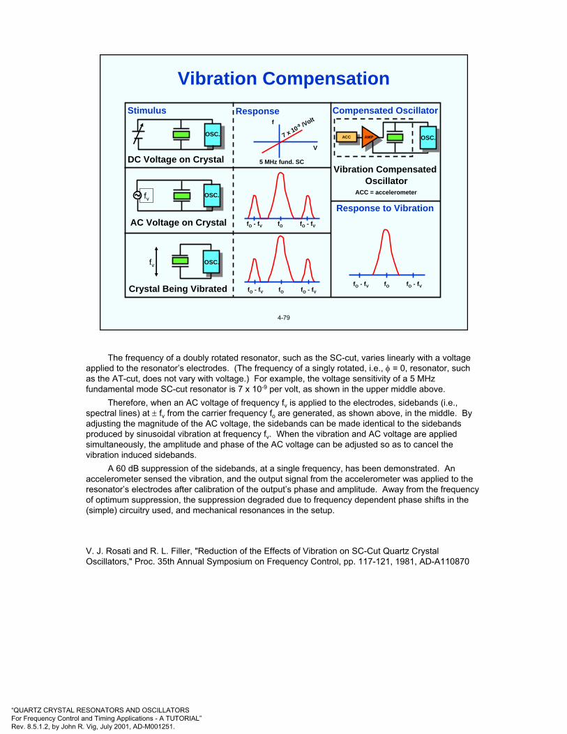
“QUARTZ CRYSTAL RESONATORS AND OSCILLATORSFor Frequency Control and Timing Applications - A TUTORIAL”Rev. 8.5.1.2, by John R. Vig, July 2001, AD-M001251.
4-79
Stimulus
OSC.
DC Voltage on Crystal
OSC.fv
AC Voltage on Crystal
OSC.fv
Crystal Being Vibrated
Responsef
7 x 10⁻⁹ /Volt
V
5 MHz fund. SC
fO - fV fO - fVfO
fO - fV fO - fVfO
ACCACC OSC.
Compensated Oscillator
AMP
Vibration Compensated Oscillator
ACC = accelerometer
Response to Vibration
fO - fV fO - fVfO
Vibration Compensation
The frequency of a doubly rotated resonator, such as the SC-cut, varies linearly with a voltage applied to the resonator’s electrodes. (The frequency of a singly rotated, i.e., φ = 0, resonator, such as the AT-cut, does not vary with voltage.) For example, the voltage sensitivity of a 5 MHz fundamental mode SC-cut resonator is 7 x 10⁻⁹ per volt, as shown in the upper middle above.
Therefore, when an AC voltage of frequency fv is applied to the electrodes, sidebands (i.e., spectral lines) at ± fv from the carrier frequency fo are generated, as shown above, in the middle. By adjusting the magnitude of the AC voltage, the sidebands can be made identical to the sidebands produced by sinusoidal vibration at frequency fv. When the vibration and AC voltage are applied simultaneously, the amplitude and phase of the AC voltage can be adjusted so as to cancel the vibration induced sidebands.
A 60 dB suppression of the sidebands, at a single frequency, has been demonstrated. An accelerometer sensed the vibration, and the output signal from the accelerometer was applied to the resonator’s electrodes after calibration of the output’s phase and amplitude. Away from the frequency of optimum suppression, the suppression degraded due to frequency dependent phase shifts in the (simple) circuitry used, and mechanical resonances in the setup.
V. J. Rosati and R. L. Filler, "Reduction of the Effects of Vibration on SC-Cut Quartz Crystal Oscillators," Proc. 35th Annual Symposium on Frequency Control, pp. 117-121, 1981, AD-A110870

“QUARTZ CRYSTAL RESONATORS AND OSCILLATORSFor Frequency Control and Timing Applications - A TUTORIAL”Rev. 8.5.1.2, by John R. Vig, July 2001, AD-M001251.
4-80
ControllerController
SignalGenerator
fV
SignalGenerator
fV
SpectrumAnalyzer
SpectrumAnalyzer
Plotter orPrinter
Plotter orPrinter
VibrationLevel
Controller
VibrationLevel
ControllerPowerAmplifierPower
AmplifierShake TableShake Table
Test OscillatorTest Oscillator
AccelerometerAccelerometer
FrequencyMultiplier
(x10)
FrequencyMultiplier
(x10)Synthesizer
(Local Oscillator)Synthesizer
(Local Oscillator)
Vibration Sensitivity Measurement System
One method of measuring Γ is illustrated above. From the vibration induced sidebands, one can calculate Γ via the equation
L(f) = 20 log (Γ•Af0/2fv)
from which it follows that Γi = (2fv/Aif0)10B, where B = L i(fv)/20
where Γi and Ai are the components of the acceleration sensitivity vector and of the acceleration, respectively, in the (unit vector) i direction. Measurements along three mutually perpendicular axes characterize Γ, which becomes
Γ = Γii+ ΓI j+ ΓkkThe local oscillator is used to mix the carrier frequency down to the range of the spectrum analyzer. If the local oscillator is not modulated, the relative sideband levels are unchanged by mixing. The frequency multiplier is used to overcome dynamic range limitations of the spectrum analyzer, using the "20 log N" enhancement discussed previously. The measured sideband levels must be adjusted for the multiplication factor prior to insertion into the above equation. (The equation is valid only if β < 0.1. )
The illustration was provided by R.L. Filler, private communication, circa 1988
J. R. Vig, C. Audoin, L. S. Cutler, M. M. Driscoll, E. P. EerNisse, R. L. Filler, R. M. Garvey, W. L. Riley, R. C. Smythe, and R. D. Weglein, "Acceleration, Vibration and Shock Effects - IEEE Standards Project P1193," Proc. 1992 IEEE Frequency Control Symposium, 763-781, 1992; also, The Effects of Acceleration on Precision Frequency Sources, U. S. Army Laboratory Command Research and Development Technical Report SLCET-TR-91-3, March 1991, AD-A235470.

“QUARTZ CRYSTAL RESONATORS AND OSCILLATORSFor Frequency Control and Timing Applications - A TUTORIAL”Rev. 8.5.1.2, by John R. Vig, July 2001, AD-M001251.
4-81
The frequency excursion during a shock is due tothe resonator’s stress sensitivity. The magnitude ofthe excursion is a function of resonator design, andof the shock induced stresses on the resonator(resonances in the mounting structure willamplify the stresses.) The permanent frequencyoffset can be due to: shock induced stresschanges, the removal of (particulate) contaminationfrom the resonator surfaces, and changes in theoscillator circuitry. Survival under shock is primarilya function of resonator surface imperfections. Chemical-polishing-produced scratch-free resonatorshave survived shocks up to 36,000 g in air gun tests,and have survived the shocks due to being fired froma 155 mm howitzer (16,000 g, 12 ms duration).
Shock
3
2
1
0
-1
-2
-3
tO t1
810Xf∆f
Shock
See chapter 5 for further information about the etching and chemical polishing of quartz crystals.The shock testing of a frequency source generally consists of measuring the frequency or phase
of the source before and after exposing the device to the specified shock. The phase deviation resulting from the shock (which is the time integral of the fractional frequency change) can provide useful information about the frequency excursion during the shock (including the possible cessation of operation).
R. L. Filler, L. J. Keres, T. M. Snowden, and J. R. Vig, "Ceramic Flatpack Enclosed AT and SC-cut Resonators," Proc. 1980 IEEE Ultrasonic Symp., pp. 819-824, 1980.
J. R. Vig, J. W. LeBus, and R. L. Filler, "Chemically Polished Quartz," Proc. of the 31st Ann. Symp. On Frequency Control, pp. 131-143, 1977

“QUARTZ CRYSTAL RESONATORS AND OSCILLATORSFor Frequency Control and Timing Applications - A TUTORIAL”Rev. 8.5.1.2, by John R. Vig, July 2001, AD-M001251.
4-82
Idealized frequency vs. time behavior for a quartz resonator following a pulse of ionizing radiation.
t0 t Time
Freq
uenc
y
fO
ft
fSS
∆fSS
fO = original, preirradiationfrequency
fSS = steady-state frequency(0.2 to 24 hours after
exposure)
∆fSS = steady-state frequencyoffset
fT = frequency at time t
10-11 for natural quartz (and R increase can stop the oscillation)∆fSS/rad* = 10-12 for cultured quartz
10-13 for swept cultured quartz
* for a 1 megarad dose (the coefficients are dose dependent)
Radiation-Induced Frequency Shifts
The above illustration shows a crystal oscillator's idealized frequency response due to a pulse of ionizing radiation. The response consists of two parts. Initially, there is a transient frequency change that is due primarily to the thermal-transient effect caused by the sudden deposition of energy into the resonator. This effect is a manifestation of the dynamic f vs. T effect discussed earlier (see “Warmupof AT- and SC-cut Resonators”). The transient effect is absent in SC-cut resonators made of high purity quartz.
In the second part of the response, after steady state is reached, there is a permanent frequency offset that is a function of the radiation dose and the nature of the crystal unit. The frequency change versus dose is nonlinear, the change per rad being much larger at low doses than at large doses. At doses above 1 kilorad (SiO2), the rate of frequency change with dose is quartz-impurity-defect dependent. For example, at a 1 megarad dose, the frequency change can be as large as 10 ppm when the crystal unit is made from natural quartz; it is typically 1 to a few ppm when the crystal is made from cultured quartz, and it can be as small as 0.02 ppm when the crystal is made from swept cultured quartz.
“The Effects of Ionizing and Particle Radiation on Precision Frequency Sources (Proposal for IEEE Standards Project P1193),” Proc. 1992 IEEE Frequency Control Symposium, pp. 798-806, 1992.
1193-1994 IEEE Guide for Measurement of Environmental Sensitivities of Standard Frequency Generators.
King, J. C., and Koehler, D. R., “Radiation Effects on Resonators” in: Precision Frequency Control, Vol. 2 (E. A. Gerber and A. Ballato, eds.), Academic Press, New York, pp. 147-159, 1985.
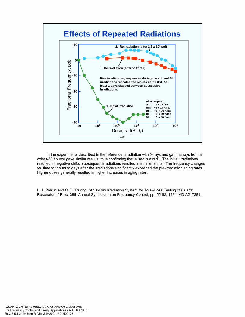
“QUARTZ CRYSTAL RESONATORS AND OSCILLATORSFor Frequency Control and Timing Applications - A TUTORIAL”Rev. 8.5.1.2, by John R. Vig, July 2001, AD-M001251.
4-83
Frac
tiona
l Fre
quen
cy, p
pb
10
0
-10
-20
-30
-4010 102 103 104 105 106
Dose, rad(SiO2)
1. Initial irradiation
2. Reirradiation (after 2.5 x 10⁴ rad)
3. Reirradiation (after >106 rad)
Five irradiations; responses during the 4th and 5th irradiations repeated the results of the 3rd. At least 2 days elapsed between successive irradiations.
Initial slopes:1st: -1 x 10⁻⁹/rad2nd: +1 x 10-11/rad3rd: +3 x 10-12/rad4th: +3 x 10-12/rad5th: +5 x 10-12/rad
Effects of Repeated Radiations
In the experiments described in the reference, irradiation with X-rays and gamma rays from a cobalt-60 source gave similar results, thus confirming that a “rad is a rad”. The initial irradiations resulted in negative shifts, subsequent irradiations resulted in smaller shifts. The frequency changes vs. time for hours to days after the irradiations significantly exceeded the pre-irradiation aging rates. Higher doses generally resulted in higher increases in aging rates.
L. J. Palkuti and Q. T. Truong, "An X-Ray Irradiation System for Total-Dose Testing of Quartz Resonators," Proc. 38th Annual Symposium on Frequency Control, pp. 55-62, 1984, AD-A217381.
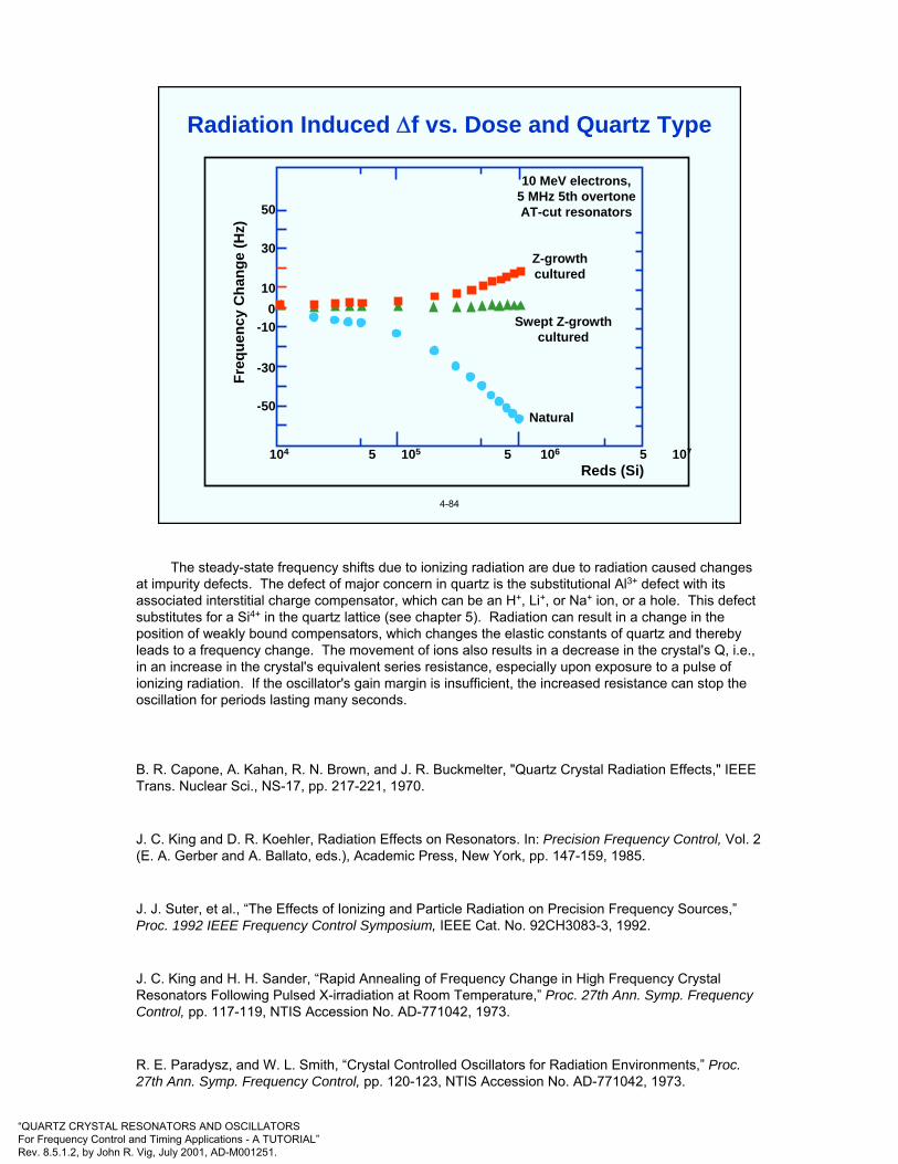
“QUARTZ CRYSTAL RESONATORS AND OSCILLATORSFor Frequency Control and Timing Applications - A TUTORIAL”Rev. 8.5.1.2, by John R. Vig, July 2001, AD-M001251.
4-84
10 MeV electrons,5 MHz 5th overtoneAT-cut resonators
Z-growthcultured
Swept Z-growthcultured
Natural
Freq
uenc
y C
hang
e (H
z)
Reds (Si)104 5 105 5 106 5 107
50
30
100
-10
-30
-50
Radiation Induced ∆f vs. Dose and Quartz Type
The steady-state frequency shifts due to ionizing radiation are due to radiation caused changes at impurity defects. The defect of major concern in quartz is the substitutional Al3+ defect with its associated interstitial charge compensator, which can be an H+, Li+, or Na+ ion, or a hole. This defect substitutes for a Si4+ in the quartz lattice (see chapter 5). Radiation can result in a change in the position of weakly bound compensators, which changes the elastic constants of quartz and thereby leads to a frequency change. The movement of ions also results in a decrease in the crystal's Q, i.e., in an increase in the crystal's equivalent series resistance, especially upon exposure to a pulse of ionizing radiation. If the oscillator's gain margin is insufficient, the increased resistance can stop the oscillation for periods lasting many seconds.
B. R. Capone, A. Kahan, R. N. Brown, and J. R. Buckmelter, "Quartz Crystal Radiation Effects," IEEE Trans. Nuclear Sci., NS-17, pp. 217-221, 1970.
J. C. King and D. R. Koehler, Radiation Effects on Resonators. In: Precision Frequency Control, Vol. 2 (E. A. Gerber and A. Ballato, eds.), Academic Press, New York, pp. 147-159, 1985.
J. J. Suter, et al., “The Effects of Ionizing and Particle Radiation on Precision Frequency Sources,”Proc. 1992 IEEE Frequency Control Symposium, IEEE Cat. No. 92CH3083-3, 1992.
J. C. King and H. H. Sander, “Rapid Annealing of Frequency Change in High Frequency Crystal Resonators Following Pulsed X-irradiation at Room Temperature,” Proc. 27th Ann. Symp. Frequency Control, pp. 117-119, NTIS Accession No. AD-771042, 1973.
R. E. Paradysz, and W. L. Smith, “Crystal Controlled Oscillators for Radiation Environments,” Proc. 27th Ann. Symp. Frequency Control, pp. 120-123, NTIS Accession No. AD-771042, 1973.
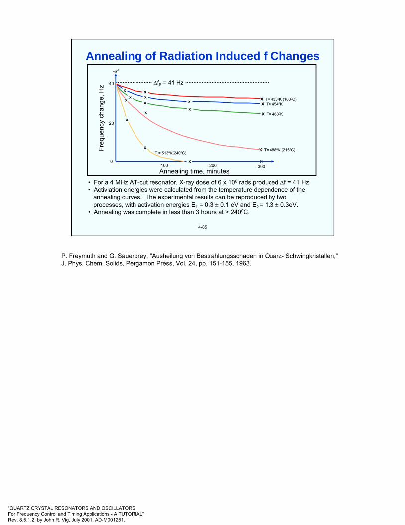
“QUARTZ CRYSTAL RESONATORS AND OSCILLATORSFor Frequency Control and Timing Applications - A TUTORIAL”Rev. 8.5.1.2, by John R. Vig, July 2001, AD-M001251.
4-85
• For a 4 MHz AT-cut resonator, X-ray dose of 6 x 10⁶ rads produced ∆f = 41 Hz.• Activiation energies were calculated from the temperature dependence of the
annealing curves. The experimental results can be reproduced by twoprocesses, with activation energies E1 = 0.3 ± 0.1 eV and E2 = 1.3 ± 0.3eV.
• Annealing was complete in less than 3 hours at > 2400C.
xxx x
x
xxx
x
x
x
x
-∆f
40
20
0
Freq
uenc
y ch
ange
, Hz
100 200 300x
∆fS = 41 Hz
X T= 4330K (1600C)X T= 4540K
X T= 4680K
X T= 4880K (2150C)
Annealing time, minutes
T = 5130K(2400C)
Annealing of Radiation Induced f Changes
P. Freymuth and G. Sauerbrey, "Ausheilung von Bestrahlungsschaden in Quarz- Schwingkristallen," J. Phys. Chem. Solids, Pergamon Press, Vol. 24, pp. 151-155, 1963.

“QUARTZ CRYSTAL RESONATORS AND OSCILLATORSFor Frequency Control and Timing Applications - A TUTORIAL”Rev. 8.5.1.2, by John R. Vig, July 2001, AD-M001251.
4-86
4
0
-4
-8
-12
-16
-20
-24
∆f/f
(pp
108 )
Time(seconds after event)
0.1 1.0 10 100 1000
X X
XX
XXX
XXX X
X
X
XX
XXXX
XX
XX
X
X
X
X
X
Experimental data, dose = 1.3 x 10⁴ rads, SC-cut
Experimental data, dose = 2.3 x 10⁴ rads, AT-cut
Model Calculation: AT-cut
X
Transient ∆f After a Pulse of γ Radiation
J. C. King and D. R. Koehler, "Radiation Effects on Resonators," in E. A. Gerber and A. Ballato, Precision Frequency Control, Vol. 1, pp. 147-159, Academic Press, 1985.
J. C. King and H. H. Sander, “Rapid Annealing of Frequency Change in High Frequency Crystal Resonators Following Pulsed X-irradiation at Room Temperature,” Proc. 27th Ann. Symp. Frequency Control, pp. 117-119, NTIS Accession No. AD-771042, 1973.
R. E. Paradysz, and W. L. Smith, “Crystal Controlled Oscillators for Radiation Environments,” Proc. 27th Ann. Symp. Frequency Control, pp. 120-123, NTIS Accession No. AD-771042, 1973.
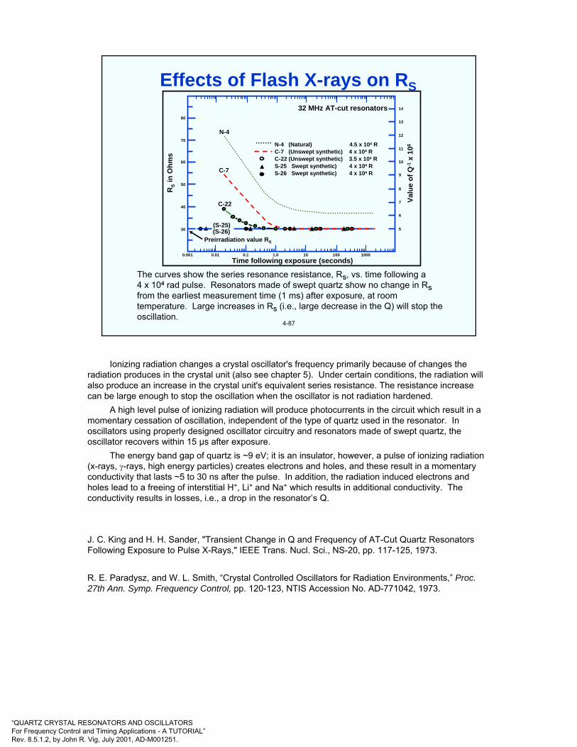
“QUARTZ CRYSTAL RESONATORS AND OSCILLATORSFor Frequency Control and Timing Applications - A TUTORIAL”Rev. 8.5.1.2, by John R. Vig, July 2001, AD-M001251.
4-87
The curves show the series resonance resistance, RS, vs. time following a4 x 104 rad pulse. Resonators made of swept quartz show no change in RSfrom the earliest measurement time (1 ms) after exposure, at room temperature. Large increases in RS (i.e., large decrease in the Q) will stop the oscillation.
RS
in O
hms
14
13
12
11
10
9
8
7
6
5
80
70
60
50
40
30
0.001 0.01 0.1 1.0 10 100 1000
Valu
e of
Q-1
x 10
6
Time following exposure (seconds)
32 MHz AT-cut resonators
Preirradiation value RS
(S-26)(S-25)
C-22
C-7
N-4
N-4 (Natural) 4.5 x 10⁴ RC-7 (Unswept synthetic) 4 x 10⁴ RC-22 (Unswept synthetic) 3.5 x 10⁴ R S-25 Swept synthetic) 4 x 10⁴ RS-26 Swept synthetic) 4 x 10⁴ R
Effects of Flash X-rays on RS
Ionizing radiation changes a crystal oscillator's frequency primarily because of changes the radiation produces in the crystal unit (also see chapter 5). Under certain conditions, the radiation will also produce an increase in the crystal unit's equivalent series resistance. The resistance increase can be large enough to stop the oscillation when the oscillator is not radiation hardened.
A high level pulse of ionizing radiation will produce photocurrents in the circuit which result in a momentary cessation of oscillation, independent of the type of quartz used in the resonator. In oscillators using properly designed oscillator circuitry and resonators made of swept quartz, the oscillator recovers within 15 µs after exposure.
The energy band gap of quartz is ~9 eV; it is an insulator, however, a pulse of ionizing radiation (x-rays, γ-rays, high energy particles) creates electrons and holes, and these result in a momentary conductivity that lasts ~5 to 30 ns after the pulse. In addition, the radiation induced electrons and holes lead to a freeing of interstitial H+, Li+ and Na+ which results in additional conductivity. The conductivity results in losses, i.e., a drop in the resonator’s Q.
J. C. King and H. H. Sander, "Transient Change in Q and Frequency of AT-Cut Quartz Resonators Following Exposure to Pulse X-Rays," IEEE Trans. Nucl. Sci., NS-20, pp. 117-125, 1973.
R. E. Paradysz, and W. L. Smith, “Crystal Controlled Oscillators for Radiation Environments,” Proc. 27th Ann. Symp. Frequency Control, pp. 120-123, NTIS Accession No. AD-771042, 1973.

“QUARTZ CRYSTAL RESONATORS AND OSCILLATORSFor Frequency Control and Timing Applications - A TUTORIAL”Rev. 8.5.1.2, by John R. Vig, July 2001, AD-M001251.
4-88
Fast Neutron Exposure (nvt) x1017
0 1 2 3 4 5 6 7 8 9 10 11 12
1000
900
800700
600
500
400
300
200100
0
Freq
uenc
y D
evia
tion,
X10
6∆
f f
5 MHzAT-cut
Slope = 0.7 x 10⁻²¹/n/cm2
Frequency Change due to Neutrons
When a fast neutron hurtles into a crystal lattice and collides with an atom, it is scattered like a billiard ball. A single such neutron can produce numerous vacancies, interstitials, and broken interatomic bonds (see next page). The effect of this "displacement damage" on oscillator frequency is dependent primarily upon the neutron fluence (and not on the type of quartz). The frequency of oscillation increases nearly linearly with neutron fluence at rates of: 8 x 10-21 neutrons per square centimeter (n/cm2) at a fluence range of 1010 to 1012 n/cm2, 5 x 10-21/n/cm2 at 1012 to 1013 n/cm2, and 0.7 x 10⁻²¹/n/cm2 at 1017 to 1018 n/cm2.
J. C. King and D. B. Fraser, "Effects of Reactor Irradiation on Thickness Shear Crystal Resonators," Proc. 16th Annual Symposium on Frequency Control, pp. 8-31, 1962, AD-285086.
T. M. Flanagan & T. F. Wrobel, “Radiation Effects in Swep-Synthetic Quartz,” IEEE Trans. Nuclear Science, vol. NS-16, pp. 130-137, Dec. 1969
W. Primak, “Extrusion of Quartz on Ion Bombardment: Further Evidence for Radiation-Induced Stress Relaxation of the Silica Network,” Phys. Rev. B, vol. 14, pp. 4679-4686, 1976.

“QUARTZ CRYSTAL RESONATORS AND OSCILLATORSFor Frequency Control and Timing Applications - A TUTORIAL”Rev. 8.5.1.2, by John R. Vig, July 2001, AD-M001251.
4-89
A fast neutron can displace about 50 to 100 atoms before it comesto rest. Most of the damage is done by the recoiling atoms. Net resultis that each neutron can cause numerous vacancies and interstitials.
(1) (2) (3) (4)
Neutron Damage
Shown above is the typical sequence of events when an energetic neutron strikes a crystal. In (1), a neutron has arrived and has dislodged a single atom. The (2), (3) and (4) drawings show how the process builds up and ends, with both the neutron and the recoiling atoms dislodging further atoms. The end result is a number of vacant sites and interstitial atoms.
F. Seitz and E. P. Wigner, “The Effects of Radiation on Solids,” Scientific American, pp. 76-84, August 1956.

“QUARTZ CRYSTAL RESONATORS AND OSCILLATORSFor Frequency Control and Timing Applications - A TUTORIAL”Rev. 8.5.1.2, by John R. Vig, July 2001, AD-M001251.
4-90
Dose vs. frequency change is nonlinear; frequency change per rad is larger at low doses.
At doses > 1 kRad, frequency change is quartz-impurity dependent. The ionizing radiation produces electron-hole pairs; the holes are trapped by the impurity Al sites while the compensating cation (e.g., Li+ or Na+) is released. The freed cations are loosely trapped along the optic axis. The lattice near the Al is altered, the elastic constant is changed; therefore, the frequency shifts. Ge impurity is also troublesome.
At a 1 MRad dose, frequency change ranges from pp 1011 per rad for natural quartz to pp 1014
per rad for high quality swept quartz.
Frequency change is negative for natural quartz; it can be positive or negative for cultured and swept cultured quartz.
Frequency change saturates at doses >> 106 rads.
Q degrades upon irradiation if the quartz contains a high concentration of alkali impurities; Q of resonators made of properly swept cultured quartz is unaffected.
High dose radiation can also rotate the f vs. T characteristic.
Frequency change anneals at T > 240°C in less than 3 hours.
Preconditioning (e.g., with doses > 105 rads) reduces the high dose radiation sensitivities upon subsequent irradiations.
At < 100 rad, frequency change is not well understood. Radiation induced stress relief & surface effects (adsorption, desorption, dissociation, polymerization and charging) may be factors.
Summary - Steady-State Radiation Results
See also “Ions in Quartz - Simplified Model,” “Aluminum Associated Defects,” and “Sweeping” in Chapter 5.
T. M. Flanagan, R. E. Leadon and D. L. Shannon, "Evaluation of Mechanisms for Low-Dose Frequency Shifts in Crystal Oscillators," Proc. 40th Ann. Symp. on Frequency Control, pp. 127-133, 1986, IEEE Cat. No. 86CH2330-9
J. C. King and D. R. Koehler, Radiation Effects on Resonators. In: Precision Frequency Control, Vol. 2 (E. A. Gerber and A. Ballato, eds.), Academic Press, New York, pp. 147-159, 1985.

“QUARTZ CRYSTAL RESONATORS AND OSCILLATORSFor Frequency Control and Timing Applications - A TUTORIAL”Rev. 8.5.1.2, by John R. Vig, July 2001, AD-M001251.
4-91
For applications requiring circuits hardened to pulse irradiation, quartz resonators are theleast tolerant element in properly designed oscillator circuits.
Resonators made of unswept quartz or natural quartz can experience a large increase in Rsfollowing a pulse of radiation. The radiation pulse can stop the oscillation.
Natural, cultured, and swept cultured AT-cut quartz resonators experience an initialnegative frequency shift immediately after exposure to a pulse of X-rays (e.g., 104 to 105 Rad of flash X-rays), ∆f/f is as large as -3ppm at 0.02sec after burst of 1012 Rad/sec.
Transient f offset anneals as t-1/2; the nonthermal-transient part of the f offset is probablydue to the diffusion and retrapping of hydrogen at the Al3+ trap.
Resonators made of properly swept quartz experience a negligibly small change in Rswhen subjected to pulsed ionizing radiation (therefore, the oscillator circuit does not require a large reserve of gain margin).
SC-cut quartz resonators made of properly swept high Q quartz do not exhibit transientfrequency offsets following a pulse of ionizing radiation.
Crystal oscillators will stop oscillating during an intense pulse of ionizing radiation becauseof the large prompt photoconductivity in quartz and in the transistors comprising theoscillator circuit. Oscillation will start up within 15µsec after a burst if swept quartz is usedin the resonator and the oscillator circuit is properly designed for the radiation environment.
Summary - Pulse Irradiation Results
-
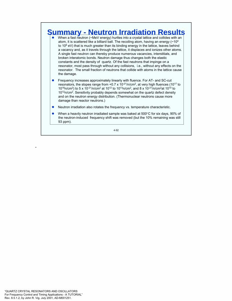
“QUARTZ CRYSTAL RESONATORS AND OSCILLATORSFor Frequency Control and Timing Applications - A TUTORIAL”Rev. 8.5.1.2, by John R. Vig, July 2001, AD-M001251.
4-92
When a fast neutron (~MeV energy) hurtles into a crystal lattice and collides with anatom, it is scattered like a billiard ball. The recoiling atom, having an energy (~104
to 106 eV) that is much greater than its binding energy in the lattice, leaves behinda vacancy and, as it travels through the lattice, it displaces and ionizes other atoms.A single fast neutron can thereby produce numerous vacancies, interstitials, andbroken interatomic bonds. Neutron damage thus changes both the elastic constants and the density of quartz. Of the fast neutrons that impinge on aresonator, most pass through without any collisions, i.e., without any effects on theresonator. The small fraction of neutrons that collide with atoms in the lattice causethe damage.
Frequency increases approximately linearly with fluence. For AT- and SC-cut resonators, the slopes range from +0.7 x 10⁻²¹/n/cm2, at very high fluences (1017 to1018n/cm2) to 5 x 10-21/n/cm2 at 1012 to 1013n/cm2, and 8 x 10-21/n/cm2at 1010 to 1012n/cm2. Sensitivity probably depends somewhat on the quartz defect densityand on the neutron energy distribution. (Thermonuclear neutrons cause moredamage than reactor neutrons.)
Neutron irradiation also rotates the frequency vs. temperature characteristic.
When a heavily neutron irradiated sample was baked at 500°C for six days, 90% ofthe neutron-induced frequency shift was removed (but the 10% remaining was still93 ppm).
Summary - Neutron Irradiation Results
-

“QUARTZ CRYSTAL RESONATORS AND OSCILLATORSFor Frequency Control and Timing Applications - A TUTORIAL”Rev. 8.5.1.2, by John R. Vig, July 2001, AD-M001251.
4-93
Electric field - affects doubly-rotated resonators; e.g., a voltage on the electrodes of a 5 MHzfundamental mode SC-cut resonator results in a ∆f/f = 7 x 10⁻⁹ per volt. The voltage can alsocause sweeping, which can affect the frequency (of all cuts), even at normal operatingtemperatures.
Magnetic field - quartz is diamagnetic, however, magnetic fields can induce Eddy currents, andwill affect magnetic materials in the resonator package and the oscillator circuitry. Induced acvoltages can affect varactors, AGC circuits and power supplies. Typical frequency change of a "good" quartz oscillator is <<10-10 per gauss.
Ambient pressure (altitude) - deformation of resonator and oscillator packages, and change inheat transfer conditions affect the frequency.
Humidity - can affect the oscillator circuitry, and the oscillator's thermal properties, e.g.,moisture absorbed by organics can affect dielectric constants.
Power supply voltage, and load impedance - affect the oscillator circuitry, and indirectly, theresonator's drive level and load reactance. A change in load impedance changes the amplitudeor phase of the signal reflected into the oscillator loop, which changes the phase (and frequency) of the oscillation. The effects can be minimized by using a (low noise) voltage regulator and buffer amplifier.
Gas permeation - stability can be affected by excessive levels of atmospheric hydrogen andhelium diffusing into "hermetically sealed" metal and glass enclosures (e.g., hydrogen diffusionthrough nickel resonator enclosures, and helium diffusion through glass Rb standard bulbs).
Other Effects on Stability
Ambient pressure change (as during an altitude change) can change a crystal oscillator's frequency if the pressure change produces a deformation of the crystal unit's or the oscillator's enclosure (thus changing stray capacitances and stresses). The pressure change can also affect the frequency indirectly through a change in heat-transfer conditions inside the oscillator. Humidity changes can also affect the heat-transfer conditions. In addition, moisture in the atmosphere will condense on surfaces when the temperature falls below the dew point, and can permeate materials such as epoxies and polyimides, and thereby affect the properties (e.g., conductivities and dielectric constants) of the oscillator circuitry. The frequency of a properly designed crystal oscillator changes less than 5 x 10⁻⁹ when the environment changes from one atmosphere of air to a vacuum. The medium and long term stability of some oscillators can be improved by controlling the pressure and humidity around the oscillators.
Electric fields can change the frequency of a crystal unit. An ideal AT-cut is not affected by a dc voltage on the crystal electrodes, but "doubly rotated cuts," such as the SC-cut, are affected. For example, the frequency of a 5-MHz fundamental mode SC-cut crystal changes 7 x 10⁻⁹ per volt. Direct-current voltages on the electrodes can also cause sweeping, which can affect the frequencies of all cuts.
Power-supply and load-impedance changes affect the oscillator circuitry and, indirectly, the crystal's drive level and load reactance. A change in load impedance changes the amplitude or phase of the signal reflected into the oscillator loop, which changes the phase (and frequency) of the oscillation. The effects can be minimized through voltage regulation and the use of buffer amplifiers. The frequency of a "good" crystal oscillator changes less than 5 x 10⁻¹⁰ for a 10% change in load impedance. The typical sensitivity of a high-quality crystal oscillator to power-supply voltage changes is 5 x 10-11/V.
Gas permeation under conditions where there is an abnormally high concentration of hydrogen or helium in the atmosphere can lead to anomalous aging rates. For example, hydrogen can permeate into "hermetically" sealed crystal units in metal enclosures, and helium can permeate through the walls of glass-enclosed crystal units, and through the glass of glass-to-metal seals.---------------------------
J. R. Vig & F. L. Walls, "Fundamental Limits on the Frequency Instabilities of Quartz Crystal Oscillators," Proc. 1994 IEEE Int'l Frequency Control Symposium, pp. 506-523, 1994
IEEE Standard 1193-1994 “IEEE Guide for Measurement of Environmental Sensitivities of Standard Frequency Generators”.
R. Brendel, “Influence Of a Magnetic Field on Quartz Crystal Resonators,” IEEE Transactions on Ultrasonics, Ferroelectrics, and Frequency Control, vol. 43 no. 5, pp. 818-831, September 1996. This paper is also available at <http://www.ieee.org/uffc/fc> .

“QUARTZ CRYSTAL RESONATORS AND OSCILLATORSFor Frequency Control and Timing Applications - A TUTORIAL”Rev. 8.5.1.2, by John R. Vig, July 2001, AD-M001251.
4-94
In attempting to measure the effect of a single influence, one often encountersinterfering influences, the presence of which may or may not be obvious.
Measurement
Resonator aging
Short term stability
Vibration sensitivity
2-g tipover sensitivity
Resonator f vs. T(static)
Radiation sensitivity
Interfering Influence
∆T due to oven T (i.e., thermistor) aging∆ drive level due to osc. circuit aging
Vibration
Induced voltages due to magnetic fields
∆T due to convection inside oven
Thermal transient effect, humidityT-coefficient of load reactances
∆T, thermal transient effect, aging
Interactions Among Influences
The various influences on frequency stability can interact in ways that lead to erroneous test results if the interfering influence is not recognized during testing. For example, building vibrations can interfere with the measurement of short-term stability. Vibration levels of 10-3 g to 10-2 g are commonly present in buildings. Therefore, if an oscillator's acceleration sensitivity is 1 x 10⁻⁹/g, then the building vibrations alone can contribute short-term instabilities at the 10-12 to 10-11 level.
The 2-g tipover test is often used to measure the acceleration sensitivity of crystal oscillators. Thermal effects can interfere with this test because, when an oscillator is turned upside down, the thermal gradients inside the oven can vary due to changes in convection currents [6]. Other examples of interfering influences include temperature and drive-level changes interfering with aging tests; induced voltages due to magnetic fields interfering with vibration-sensitivity tests; and the thermal-transient effect, humidity changes, and the effect of load-reactance temperature coefficient interfering with the measurement of crystal units' static f vs. T characteristics.
An important effect in TCXOs is the interaction between the frequency adjustment during calibration and the f vs. T stability [71]. This phenomenon is called the trim effect.
IEEE Standard 1193-1994 “IEEE Guide for Measurement of Environmental Sensitivities of Standard Frequency Generators”.
Series of papers on IEEE Standard 1193 in the Proc. 1992 IEEE Frequency Control Symposium, pp. 762-830, 1992.
S. R. Stein and J. R. Vig, Frequency Standards for Communications, U. S. Army Laboratory Command Research and Development Technical Report SLCET-TR-91-2, January 1991, AD-A231990
“QUARTZ CRYSTAL RESONATORS AND OSCILLATORSFor Frequency Control and Timing Applications - A TUTORIAL”Rev. 8.5.1.2, by John R. Vig, July 2001, AD-M001251.
5
CHAPTER 5Quartz Material Properties
Quartz for the National Defense Stockpile, Report of the Committee on Cultured Quartz for the National Defense Stockpile, National Materials Advisory Board Commission on Engineering and Technical Systems, National Research Council, NMAB - 424, National Academy Press, Washington, D.C., 1985.
R. W. Ward, “The Constants of Alpha Quartz,” Proc. 38th Ann. Symposium on Frequency Control, pp. 22-31, 1984.
L. E. Halliburton, J. J. Martin and D. R. Koehler, “Properties of Piezoelectric Materials,” in E. A. Gerber and A. Ballato, Precision Frequency Control, Vol. 1, pp. 1-45, Academic Press, 1985.
C. Frondel, The System of Mineralogy, Vol. III, “Silica Minerals”, John Wiley and Sons, Inc., New York, 1962.
J. C. Brice, “Crystals for Quartz Resonators,” Reviews of Modern Physics, Vol. 57, No. 1, pp. 105-146, January 1985.
J. A. Weil, “A Review of Electron Spin Spectroscopy and Its Application to the Study of Paramagnetic Defects in Crystalline Quartz,” Physics and Chemistry of Minerals, vol. 10, pp. 149-165, 1984.

“QUARTZ CRYSTAL RESONATORS AND OSCILLATORSFor Frequency Control and Timing Applications - A TUTORIAL”Rev. 8.5.1.2, by John R. Vig, July 2001, AD-M001251.
5-1
• The autoclave is filled to some predetermined factor with water plus mineralizer (NaOH or Na2CO3).
• The baffle localizes the temperature gradient so that each zone is nearly isothermal.
• The seeds are thin slices of (usually) Z-cut single crystals.
• The nutrient consists of small (~2½ to 4 cm) pieces of single-crystal quartz (“lascas”).
• The temperatures and pressures are typically about 3500C and 800 to 2,000 atmospheres; T2 - T1 is typically 40C to 100C.
• The nutrient dissolves slowly (30 to 260 days per run), diffuses to the growth zone, and deposits onto the seeds.
Cover
Closurearea
Autoclave
Seeds
Baffle
Solute-nutrient
Nutrient dissolving
zone, T2
T2 > T1
Growthzone, T1
Nutrient
Hydrothermal Growth of Quartz
Prior to ~1956, the material used for quartz resonators was natural quartz, i.e., mined quartz. Today, it is “cultured quartz,” i.e., quartz grown in factories. Although this quartz is often referred to as “synthetic quartz,” nobody has yet found a way to synthesize single crystal quartz directly from silicon and oxygen. Large quartz bars (typically ~15 cm long) of uniform size and shape are grown from small, irregularly shaped pieces of quartz (called “lascas” by the culturing process described above. So, strictly speaking, the quartz is “cultured quartz”.
Quartz is a common material in the earth’s crust (e.g., sand is mostly quartz), however, the high purity crystals needed for quartz growing are not so common. Most of the nutrient materials used by quartz growers are mined in Brazil and the USA (near Jessieville, Arkansas).
The autoclave is a long, thick-walled ~25 to 100 cm inner diameter steel tube that can withstand the high temperatures and pressures of the growth process.
The anisotropy of quartz is discussed on the next page, and in chapter 3, where it is pointed out that the highest etching rate direction is the Z-direction. Similarly, during quartz growing, the Z-direction is the fastest direction of growth.
R. A. Laudise and R. L. Barns, “Perfection of Quartz and Its Connection to Crystal Growth,” IEEE Transactions on Ultrasonics, Ferroelectrics, and Frequency Control, Vol. 35, No. 3, pp. 277-287, May 1988, IEEE Catalog 88CH2588-2.
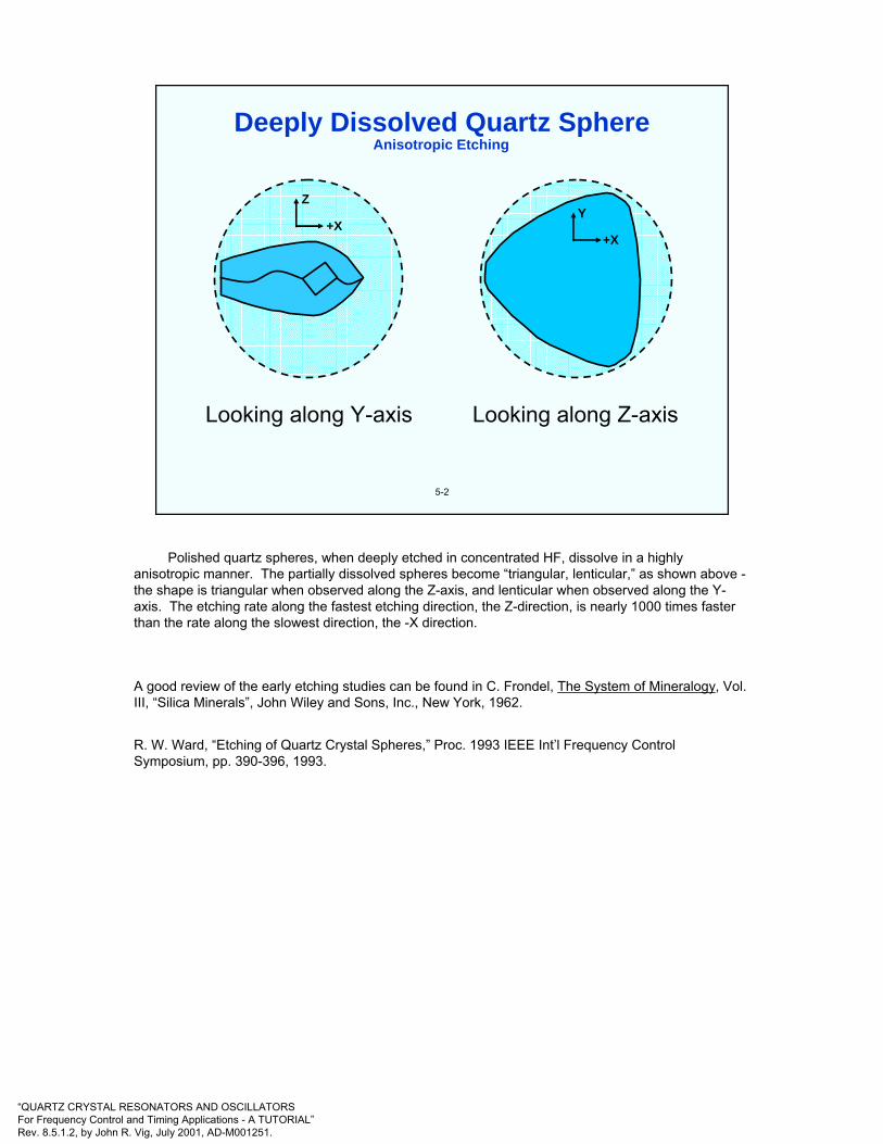
“QUARTZ CRYSTAL RESONATORS AND OSCILLATORSFor Frequency Control and Timing Applications - A TUTORIAL”Rev. 8.5.1.2, by John R. Vig, July 2001, AD-M001251.
Anisotropic Etching
5-2
Y
+X
Z
+X
Looking along Y-axis Looking along Z-axis
Deeply Dissolved Quartz Sphere
Polished quartz spheres, when deeply etched in concentrated HF, dissolve in a highly anisotropic manner. The partially dissolved spheres become “triangular, lenticular,” as shown above -the shape is triangular when observed along the Z-axis, and lenticular when observed along the Y-axis. The etching rate along the fastest etching direction, the Z-direction, is nearly 1000 times faster than the rate along the slowest direction, the -X direction.
A good review of the early etching studies can be found in C. Frondel, The System of Mineralogy, Vol. III, “Silica Minerals”, John Wiley and Sons, Inc., New York, 1962.
R. W. Ward, “Etching of Quartz Crystal Spheres,” Proc. 1993 IEEE Int’l Frequency Control Symposium, pp. 390-396, 1993.
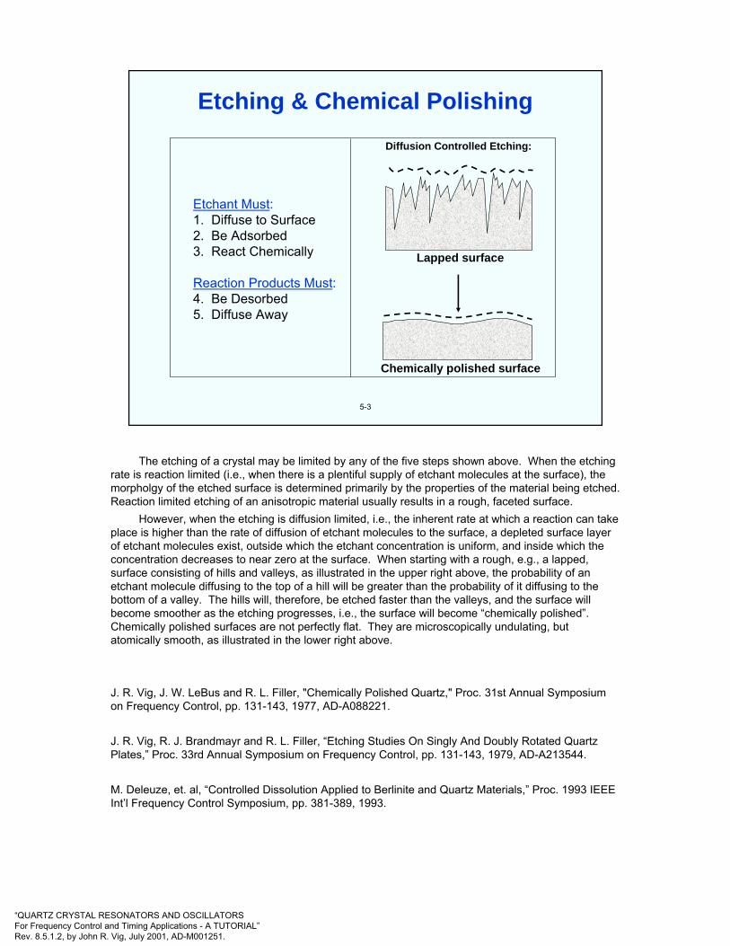
“QUARTZ CRYSTAL RESONATORS AND OSCILLATORSFor Frequency Control and Timing Applications - A TUTORIAL”Rev. 8.5.1.2, by John R. Vig, July 2001, AD-M001251.
5-3
Etchant Must:1. Diffuse to Surface2. Be Adsorbed3. React Chemically
Reaction Products Must:4. Be Desorbed5. Diffuse Away
Diffusion Controlled Etching:
Lapped surface
Chemically polished surface
Etching & Chemical Polishing
The etching of a crystal may be limited by any of the five steps shown above. When the etching rate is reaction limited (i.e., when there is a plentiful supply of etchant molecules at the surface), the morpholgy of the etched surface is determined primarily by the properties of the material being etched. Reaction limited etching of an anisotropic material usually results in a rough, faceted surface.
However, when the etching is diffusion limited, i.e., the inherent rate at which a reaction can take place is higher than the rate of diffusion of etchant molecules to the surface, a depleted surface layer of etchant molecules exist, outside which the etchant concentration is uniform, and inside which the concentration decreases to near zero at the surface. When starting with a rough, e.g., a lapped, surface consisting of hills and valleys, as illustrated in the upper right above, the probability of an etchant molecule diffusing to the top of a hill will be greater than the probability of it diffusing to the bottom of a valley. The hills will, therefore, be etched faster than the valleys, and the surface will become smoother as the etching progresses, i.e., the surface will become “chemically polished”. Chemically polished surfaces are not perfectly flat. They are microscopically undulating, but atomically smooth, as illustrated in the lower right above.
J. R. Vig, J. W. LeBus and R. L. Filler, "Chemically Polished Quartz," Proc. 31st Annual Symposium on Frequency Control, pp. 131-143, 1977, AD-A088221.
J. R. Vig, R. J. Brandmayr and R. L. Filler, “Etching Studies On Singly And Doubly Rotated Quartz Plates,” Proc. 33rd Annual Symposium on Frequency Control, pp. 131-143, 1979, AD-A213544.
M. Deleuze, et. al, “Controlled Dissolution Applied to Berlinite and Quartz Materials,” Proc. 1993 IEEE Int’l Frequency Control Symposium, pp. 381-389, 1993.
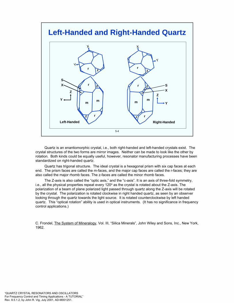
“QUARTZ CRYSTAL RESONATORS AND OSCILLATORSFor Frequency Control and Timing Applications - A TUTORIAL”Rev. 8.5.1.2, by John R. Vig, July 2001, AD-M001251.
5-4
Y
X
r z zr
Y
X
rr zz
m m mm
rrz z
Y
Z
Left-Handed Right-Handed
Y
Z
SX
SX
Left-Handed and Right-Handed Quartz
Quartz is an enantiomorphic crystal, i.e., both right-handed and left-handed crystals exist. The crystal structures of the two forms are mirror images. Neither can be made to look like the other by rotation. Both kinds could be equally useful, however, resonator manufacturing processes have been standardized on right-handed quartz.
Quartz has trigonal structure. The ideal crystal is a hexagonal prism with six cap faces at each end. The prism faces are called the m-faces, and the major cap faces are called the r-faces; they are also called the major rhomb faces. The z-faces are called the minor rhomb faces.
The Z-axis is also called the “optic axis,” and the “c-axis”. It is an axis of three-fold symmetry, i.e., all the physical properties repeat every 120o as the crystal is rotated about the Z-axis. The polarization of a beam of plane polarized light passed through quartz along the Z-axis will be rotated by the crystal. The polarization is rotated clockwise in right handed quartz, as seen by an observer looking through the quartz towards the light source. It is rotated counterclockwise by left handed quartz. This “optical rotation” ability is used in optical instruments. (It has no significance in frequency control applications.)
C. Frondel, The System of Mineralogy, Vol. III, “Silica Minerals”, John Wiley and Sons, Inc., New York, 1962.

“QUARTZ CRYSTAL RESONATORS AND OSCILLATORSFor Frequency Control and Timing Applications - A TUTORIAL”Rev. 8.5.1.2, by John R. Vig, July 2001, AD-M001251.
5-5
Si Si
Si Si
O
O
O
O
Si
109o
Z
Y
144.2o
The Quartz Lattice
For pure α-quartz, the lattice constant a = 0.4913 nm and c/a = 1.10013. Impurities increase the a lattice constant, and decrease the axial ratio c/a. Small differences between natural quartz and cultured quartz, and between cultured quartz and swept cultured quartz have been measured. Pressure also affects the lattice constants.
The average Si-O bond length is 0.1607 nm, the O-Si-O bond angles vary from 108.3o to 110.7o
and the Si-O-Si bond angle is 144.2o.
J. D. Jorgensen, “Compression Mechanisms in α-Quartz Structures - SiO2 and GeO2,” J. Appl. Phys. Vol 49, pp. 5473-78, 1978.
J. C. Brice, The Lattice Constants of a-Quartz," J. Materials Science, vol. 15, pp. 161-167, 1980.
R. W. Ward, “The Constants of Alpha Quartz,” Proc. 38th Ann. Symposium on Frequency Control, pp. 22-31, 1984.

“QUARTZ CRYSTAL RESONATORS AND OSCILLATORSFor Frequency Control and Timing Applications - A TUTORIAL”Rev. 8.5.1.2, by John R. Vig, July 2001, AD-M001251.
5-6
Quartz Property
Q
Purity (Al, Fe, Li, Na, K,-OH, H2O)
Crystalline Perfection,Strains
Inclusions
Device and Device-Fabrication Property
Oscillator short-term stability, phase noiseclose to carrier, long-term stability, filter loss
Radiation hardness, susceptibility to twinning,optical characteristics
Sweepability, etchability for chem. polishingand photolithographic processing, opticalproperties, strength, aging(?), hysteresis(?)
High-temperature processing and applications,resonator Q, optical characteristics, etchability
Quartz Properties’ Effects on Device Properties
-
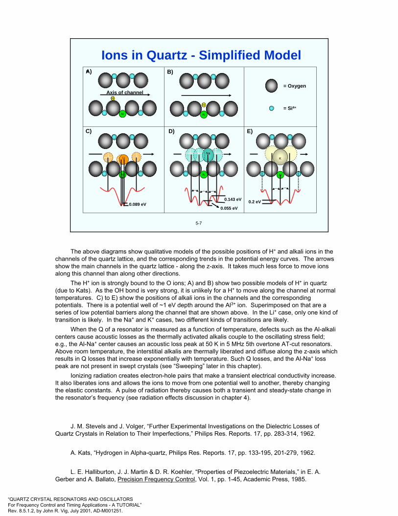
“QUARTZ CRYSTAL RESONATORS AND OSCILLATORSFor Frequency Control and Timing Applications - A TUTORIAL”Rev. 8.5.1.2, by John R. Vig, July 2001, AD-M001251.
5-7
= Oxygen
= Si4+
Al
HAxis of channel
Al
H
Al
Li
0.089 eV
Al
Na
0.143 eV
0.055 eV
Al
K
0.2 eV
A)
E)D)C)
B)a
Ions in Quartz - Simplified Model
The above diagrams show qualitative models of the possible positions of H+ and alkali ions in the channels of the quartz lattice, and the corresponding trends in the potential energy curves. The arrows show the main channels in the quartz lattice - along the z-axis. It takes much less force to move ions along this channel than along other directions.
The H+ ion is strongly bound to the O ions; A) and B) show two possible models of H+ in quartz (due to Kats). As the OH bond is very strong, it is unlikely for a H+ to move along the channel at normal temperatures. C) to E) show the positions of alkali ions in the channels and the corresponding potentials. There is a potential well of ~1 eV depth around the Al3+ ion. Superimposed on that are a series of low potential barriers along the channel that are shown above. In the Li+ case, only one kind of transition is likely. In the Na+ and K+ cases, two different kinds of transitions are likely.
When the Q of a resonator is measured as a function of temperature, defects such as the Al-alkali centers cause acoustic losses as the thermally activated alkalis couple to the oscillating stress field; e.g., the Al-Na+ center causes an acoustic loss peak at 50 K in 5 MHz 5th overtone AT-cut resonators. Above room temperature, the interstitial alkalis are thermally liberated and diffuse along the z-axis which results in Q losses that increase exponentially with temperature. Such Q losses, and the Al-Na+ loss peak are not present in swept crystals (see “Sweeping” later in this chapter).
Ionizing radiation creates electron-hole pairs that make a transient electrical conductivity increase. It also liberates ions and allows the ions to move from one potential well to another, thereby changing the elastic constants. A pulse of radiation thereby causes both a transient and steady-state change in the resonator’s frequency (see radiation effects discussion in chapter 4).
J. M. Stevels and J. Volger, “Further Experimental Investigations on the Dielectric Losses of Quartz Crystals in Relation to Their Imperfections,” Philips Res. Reports. 17, pp. 283-314, 1962.
A. Kats, “Hydrogen in Alpha-quartz, Philips Res. Reports. 17, pp. 133-195, 201-279, 1962.
L. E. Halliburton, J. J. Martin & D. R. Koehler, “Properties of Piezoelectric Materials,” in E. A. Gerber and A. Ballato, Precision Frequency Control, Vol. 1, pp. 1-45, Academic Press, 1985.
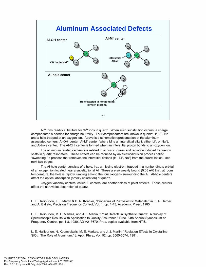
“QUARTZ CRYSTAL RESONATORS AND OSCILLATORSFor Frequency Control and Timing Applications - A TUTORIAL”Rev. 8.5.1.2, by John R. Vig, July 2001, AD-M001251.
Ox
OxOx
OxOx
Ox
Ox
Ox
H+M+ Al3+
Al3+
Al3+
Ox
OxOx
Al-OH center
OH molecule
Al-M+ center
InterstitialAlkali
5-8
Hole trapped in nonbondingoxygen p orbital
h+
Al-hole center
Aluminum Associated Defects
Al3+ ions readily substitute for Si4+ ions in quartz. When such substitution occurs, a charge compensator is needed for charge neutrality. Four compensators are known in quartz: H+, Li+, Na+
and a hole trapped at an oxygen ion. Above is a schematic representation of the aluminum associated centers: Al-OH- center, Al-M+ center (where M is an interstitial alkali, either Li+, or Na+), and Al-hole center. The Al-OH- center is formed when an interstitial proton bonds to an oxygen ion.
The aluminum related centers are related to acoustic losses and radiation induced frequency shifts in quartz resonators. These effects can be reduced by an electrodiffusion process called “sweeping,” a process that removes the interstitial cations (H+, Li+, Na+) from the quartz lattice - see next two pages.
The Al-hole center consists of a hole, i.e., a missing electron, trapped in a nonbonding p orbital of an oxygen ion located near a substitutional Al. These are so weakly bound (0.03 eV) that, at room temperature, the hole is rapidly jumping among the four oxygens surrounding the Al. Al-hole centers affect the optical absorption (smoky coloration) of quartz.
Oxygen vacancy centers, called E’ centers, are another class of point defects. These centers affect the ultraviolet absorption of quartz.
L. E. Halliburton, J. J. Martin & D. R. Koehler, “Properties of Piezoelectric Materials,” in E. A. Gerber and A. Ballato, Precision Frequency Control, Vol. 1, pp. 1-45, Academic Press, 1985.
L. E. Halliburton, M. E. Markes, and J. J. Martin, “Point Defects in Synthetic Quartz: A Survey of Spectroscopic Results With Application to Quality Assurance,” Proc. 34th Annual Symposium on Frequency Control, pp. 1-8, 1980, AD-A213670. Proc. copies available from NTIS.
L. E. Halliburton, N. Koumvakalis, M. E. Markes, and J. J. Martin, “Radiation Effects in Crystalline SiO2: The Role of Aluminum,” J. Appl. Phys., Vol. 52, pp. 3565-3574, 1981.
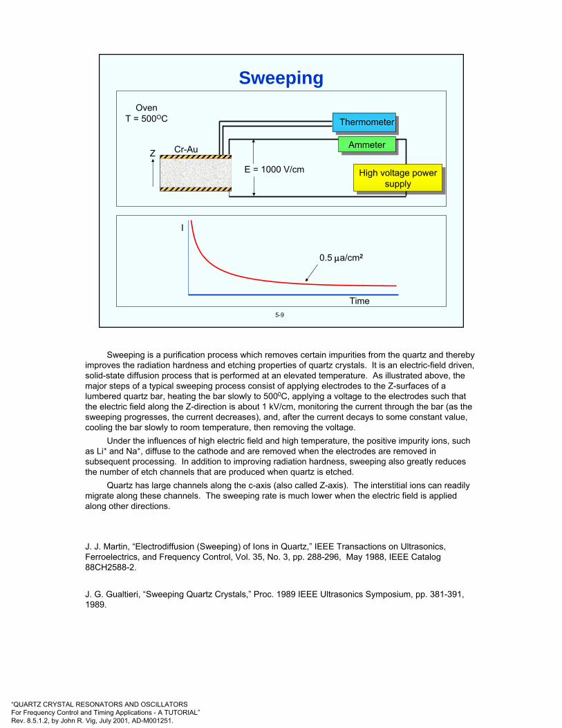
“QUARTZ CRYSTAL RESONATORS AND OSCILLATORSFor Frequency Control and Timing Applications - A TUTORIAL”Rev. 8.5.1.2, by John R. Vig, July 2001, AD-M001251.
High voltage powersupply
Thermometer
AmmeterZ Cr-Au
OvenT = 500OC
E = 1000 V/cm
5-9
I
Time
0.5 µa/cm2
Quartz bar
Sweeping
Sweeping is a purification process which removes certain impurities from the quartz and thereby improves the radiation hardness and etching properties of quartz crystals. It is an electric-field driven, solid-state diffusion process that is performed at an elevated temperature. As illustrated above, the major steps of a typical sweeping process consist of applying electrodes to the Z-surfaces of a lumbered quartz bar, heating the bar slowly to 5000C, applying a voltage to the electrodes such that the electric field along the Z-direction is about 1 kV/cm, monitoring the current through the bar (as the sweeping progresses, the current decreases), and, after the current decays to some constant value, cooling the bar slowly to room temperature, then removing the voltage.
Under the influences of high electric field and high temperature, the positive impurity ions, such as Li+ and Na+, diffuse to the cathode and are removed when the electrodes are removed in subsequent processing. In addition to improving radiation hardness, sweeping also greatly reduces the number of etch channels that are produced when quartz is etched.
Quartz has large channels along the c-axis (also called Z-axis). The interstitial ions can readily migrate along these channels. The sweeping rate is much lower when the electric field is applied along other directions.
J. J. Martin, “Electrodiffusion (Sweeping) of Ions in Quartz,” IEEE Transactions on Ultrasonics, Ferroelectrics, and Frequency Control, Vol. 35, No. 3, pp. 288-296, May 1988, IEEE Catalog 88CH2588-2.
J. G. Gualtieri, “Sweeping Quartz Crystals,” Proc. 1989 IEEE Ultrasonics Symposium, pp. 381-391, 1989.

“QUARTZ CRYSTAL RESONATORS AND OSCILLATORSFor Frequency Control and Timing Applications - A TUTORIAL”Rev. 8.5.1.2, by John R. Vig, July 2001, AD-M001251.
5-10
• Infrared absorption coefficient*
• Etch-channel density *
• Etch-pit density
• Inclusion density *
• Acoustic attenuation
• Impurity analysis
• X-ray topography
• UV absorption
• Birefringence along the optic axis
• Thermal shock induced fracture
• Electron spin resonance
• ? ? ?
* EIA Standard 477-1 contains standard test method for this quantity
Quartz Quality Indicators
The first four tests listed above are the most commonly used quality indicators.
G. R. Johnson and R. A. Irvine, “Etch Channels in Single Crystal Cultured Quartz,” Proc. 41st Annual Symposium on Frequency Control, pp. 175-182, 1987, IEEE Catalog No. 87CH2427-3.
J. R. Vig, J. W. LeBus and R. L. Filler, "Chemically Polished Quartz," Proc. 31st Annual Symposium on Frequency Control, pp. 131-143, 1977, AD-A088221. Proc. copies available from NTIS.

“QUARTZ CRYSTAL RESONATORS AND OSCILLATORSFor Frequency Control and Timing Applications - A TUTORIAL”Rev. 8.5.1.2, by John R. Vig, July 2001, AD-M001251.
5-11
Tran
smis
sion
(%)
Wave number (cm-1)
20
40
60
80
100
0
2.5 3.0 3.5 4.0
3500
3585
33003200
3410
4000 3500 3000 2500
E parallel to Z
E parallel to X
Infrared Absorption of Quartz
The importance of Q, and the factors that influence it, are discussed in chapter 3. The Q of a resonator is due to a combination of factors, one of which is the quartz material. The material can limit a resonator’s Q, but the contribution of the material cannot be determined from measuring the Q of a resonator.
Infrared absorption by the quartz material used to make a resonator correlates well with the maximum Q achievable with that resonator, at a particular frequency; 5 MHz is the standard frequency used for correlations. The figure above shows the transmission spectra of a 20 mm thick sample, with the IR incident along two perpendicular directions, X and Z.
“Infrared Q” measurements, per EIA Standard 477-1, are routinely used by quartz growers and users as an indicator of quartz quality (see next page).
J. C. Brice and A. M. Cole, "The Characterization of Synthetic Quartz by Using Infrared Absorption," Proc. 32nd Annual Symposium on Frequency Control, pp. 1-10, 1978.
B. Sawyer, "Quality Indications From Infrared Absorption Measurements on Cultured Quartz," IEEE Transactions on Ultrasonics, Ferroelectrics, and Frequency Control, Vol. UFFC-34, No. 5, pp. 558-565, September 1987.
D. M. Dodd and D. B. Fraser, “Infra-red Studies of the Variation of H-bonded OH in Synthetic α-Quartz,” J. Phys. Chem. Solids, vol. 26, pp. 673-686, 1965.

“QUARTZ CRYSTAL RESONATORS AND OSCILLATORSFor Frequency Control and Timing Applications - A TUTORIAL”Rev. 8.5.1.2, by John R. Vig, July 2001, AD-M001251.
5-12
One of the factors that determine the maximum achievable resonator Q is the OH content of the quartz. Infrared absorption measurements are routinely used to measure the intensities of the temperature-broadened OH defect bands. The infrared absorption coefficient α is defined by EIA Standard 477-1 as
Y-cut thickness in cmα =A (3500 cm-1) - A (3800 cm-1)
where the A’s are the logarithm (base 10) of the fraction of the incident beam absorbed at the wave numbers in the parentheses.
* In millions, at 5 MHz (α is a quality indicator for unswept quartz only).
GradeABCDE
α, in cm-1
0.030.0450.060
0.120.25
Approx. max. Q*3.02.21.81.00.5
Infrared Absorption Coefficient
EIA Standard 477-1, available from Electronic Industries Alliance, 2500 Wilson Blvd., Arlington, VA 22201-3834, USA, Tel: +1 703 907 7500, <http://www.eia.org>
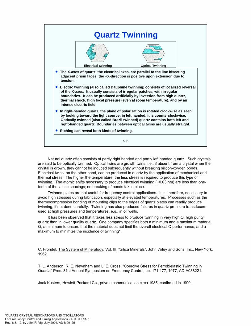
“QUARTZ CRYSTAL RESONATORS AND OSCILLATORSFor Frequency Control and Timing Applications - A TUTORIAL”Rev. 8.5.1.2, by John R. Vig, July 2001, AD-M001251.
Electrical twinning Optical Twinning
• The X-axes of quartz, the electrical axes, are parallel to the line bisectingadjacent prism faces; the +X-direction is positive upon extension due totension.
• Electric twinning (also called Dauphiné twinning) consists of localized reversalof the X-axes. It usually consists of irregular patches, with irregularboundaries. It can be produced artificially by inversion from high quartz,thermal shock, high local pressure (even at room temperature), and by anintense electric field.
• In right-handed quartz, the plane of polarization is rotated clockwise as seenby looking toward the light source; in left handed, it is counterclockwise.Optically twinned (also called Brazil twinned) quartz contains both left andright-handed quartz. Boundaries between optical twins are usually straight.
• Etching can reveal both kinds of twinning.
5-13
>>> >>>>>>> >>>>>>>>>>>> >
>>
>>
> >>> >>>>
>> >>>
>> >> >>
>
>> >>>>
>>>> >
>>
> >>> >>>>> >>> >>>>> >>> >>>>
> >>> >>>>> >>> >>>>
> > >>>>
> >>
> >>>>>
>>>
>>
>>
> >>> >>>>
>>
>>
> >> >>>
>>>
>
>
>>
>>>
∧∧∧∧∧∧∧∧∧∧∧∧∧∧∧∧∧∧∧∧ ∧∧∧∧ ∧∧∧∧∧∧∧∧∧∧∧∧∧ ∧∧
∧∧∧∧∧ ∧ ∧∧ ∧∧∧∧∧∧∧∧∧∧∧∧∧ ∧∧∧
∧∧∧
∧ ∧∧∧
∧∧∧∧∧∧∧∧∧∧∧∧
∧ ∧
∧
∧
∧∧∧∧∧∧∧∧∧∧∧∧∧∧∧∧∧∧∧∧∧∧∧∧∧∧
∧∧ ∧∧ ∧ ∧
∧∧∧
∧∧∧∧∧∧∧∧∧ ∧∧∧∧
Quartz Twinning
Natural quartz often consists of partly right handed and partly left handed quartz. Such crystals are said to be optically twinned. Optical twins are growth twins, i.e., if absent from a crystal when the crystal is grown, they cannot be induced subsequently without breaking silicon-oxygen bonds. Electrical twins, on the other hand, can be produced in quartz by the application of mechanical and thermal stress. The higher the temperature, the less stress is required to produce this type of twinning. The atomic shifts necessary to produce electrical twinning (~0.03 nm) are less than one-tenth of the lattice spacings; no breaking of bonds takes place.
Twinned plates are not useful for frequency control applications. It is, therefore, necessary to avoid high stresses during fabrication, especially at elevated temperatures. Processes such as the thermocompression bonding of mounting clips to the edges of quartz plates can readily produce twinning, if not done carefully. Twinning has also produced failures in quartz pressure transducers used at high pressures and temperatures, e.g., in oil wells.
It has been observed that it takes less stress to produce twinning in very high Q, high purity quartz than in lower quality quartz. One company specifies both a minimum and a maximum material Q; a minimum to ensure that the material does not limit the overall electrical Q performance, and a maximum to minimize the incidence of twinning*.
C. Frondel, The System of Mineralogy, Vol. III, “Silica Minerals”, John Wiley and Sons, Inc., New York, 1962.
T. L. Anderson, R. E. Newnham and L. E. Cross, "Coercive Stress for Ferrobielastic Twinning in Quartz," Proc. 31st Annual Symposium on Frequency Control, pp. 171-177, 1977, AD-A088221.
Jack Kusters, Hewlett-Packard Co., private communication circa 1985, confirmed in 1999.
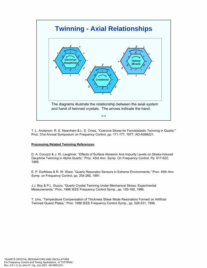
“QUARTZ CRYSTAL RESONATORS AND OSCILLATORSFor Frequency Control and Timing Applications - A TUTORIAL”Rev. 8.5.1.2, by John R. Vig, July 2001, AD-M001251.
5-14
The diagrams illustrate the relationship between the axial systemand hand of twinned crystals. The arrows indicate the hand.
Electrical(Dauphine)
Combined
Optical(Brazil)
+
+
+
+
+
+
+
+
+
+
+
++
+
++
+
+--
-
--
-
-
-
-
-
-
-
-
-
-
-
-
-
Z
Z Z
Z
ZZ
Z
Z
Z Z
ZZ
Z Z
Z
ZZ
Z
rr
rr
r
r
rr
r
r r
r
rr
r
r
r r
Twinning - Axial Relationships
T. L. Anderson, R. E. Newnham & L. E. Cross, "Coercive Stress for Ferrobielastic Twinning in Quartz," Proc. 31st Annual Symposium on Frequency Control, pp. 171-177, 1977, AD-A088221.
Processing Related Twinning References:
D. A. Cocuzzi & J. W. Laughner, “Effects of Surface Abrasion And Impurity Levels on Stress-induced Dauphine Twinning in Alpha Quartz,” Proc. 43rd Ann. Symp. On Frequency Control, Pp. 617-622, 1989.
E. P. EerNisse & R. W. Ward, “Quartz Resonator Sensors in Extreme Environments,” Proc. 45th Ann. Symp. on Frequency Control, pp. 254-260, 1991.
J.J. Boy & P.L. Guzzo, “Quartz Crystal Twinning Under Mechanical Stress: Experimental Measurements,” Proc. 1996 IEEE Frequency Control Symp., pp. 155-160, 1996.
T. Uno, “Temperature Compensation of Thickness Shear Mode Resonators Formed on Artificial Twinned Quartz Plates,” Proc. 1996 IEEE Frequency Control Symp., pp. 526-531, 1996.

“QUARTZ CRYSTAL RESONATORS AND OSCILLATORSFor Frequency Control and Timing Applications - A TUTORIAL”Rev. 8.5.1.2, by John R. Vig, July 2001, AD-M001251.
5-15
Z-axis projection showing electric (Dauphiné)twins separated by a twin wall of one unit cellthickness. The numbers in the atoms areatom heights expressed in units of percent ofa unit cell height. The atom shifts duringtwinning involve motions of <0.03 nm.
33 4567
21 2100
79
6745
12
21
4567
3388
55
7900
88
7900
88
Silicon
Oxygen
DomainWall
Quartz Lattice and Twinning
T. L. Anderson, R. E. Newnham and L. E. Cross, "Coercive Stress for Ferrobielastic Twinning in Quartz," Proc. 31st Annual Symposium on Frequency Control, pp. 171-177, 1977, AD-A088221. Proc. copies available from NTIS.
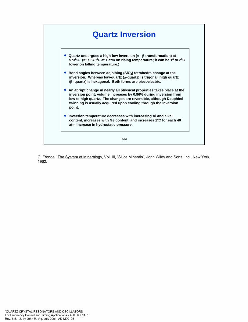
“QUARTZ CRYSTAL RESONATORS AND OSCILLATORSFor Frequency Control and Timing Applications - A TUTORIAL”Rev. 8.5.1.2, by John R. Vig, July 2001, AD-M001251.
5-16
• Quartz undergoes a high-low inversion (α - β transformation) at5730C. (It is 5730C at 1 atm on rising temperature; it can be 10 to 20Clower on falling temperature.)
• Bond angles between adjoining (SiO4) tetrahedra change at theinversion. Whereas low-quartz (α-quartz) is trigonal, high quartz(β -quartz) is hexagonal. Both forms are piezoelectric.
• An abrupt change in nearly all physical properties takes place at theinversion point; volume increases by 0.86% during inversion fromlow to high quartz. The changes are reversible, although Dauphinétwinning is usually acquired upon cooling through the inversionpoint.
• Inversion temperature decreases with increasing Al and alkalicontent, increases with Ge content, and increases 10C for each 40atm increase in hydrostatic pressure.
Quartz Inversion
C. Frondel, The System of Mineralogy, Vol. III, “Silica Minerals”, John Wiley and Sons, Inc., New York, 1962.
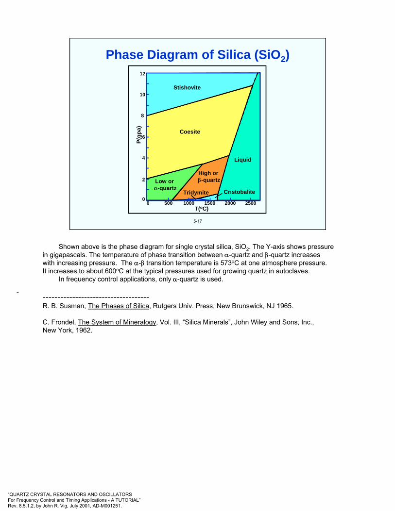
“QUARTZ CRYSTAL RESONATORS AND OSCILLATORSFor Frequency Control and Timing Applications - A TUTORIAL”Rev. 8.5.1.2, by John R. Vig, July 2001, AD-M001251.
5-17
Low or α-quartz
High or β-quartz
CristobaliteTridymite
Liquid
Coesite
Stishovite
P(gp
a)
12
10
8
6
4
2
00 500 1000 1500 2000 2500
T(oC)
Phase Diagram of Silica (SiO2)
-
Shown above is the phase diagram for single crystal silica, SiO2. The Y-axis shows pressure in gigapascals. The temperature of phase transition between α-quartz and β-quartz increases with increasing pressure. The α-β transition temperature is 573oC at one atmosphere pressure. It increases to about 600oC at the typical pressures used for growing quartz in autoclaves.
In frequency control applications, only α-quartz is used.
------------------------------------R. B. Susman, The Phases of Silica, Rutgers Univ. Press, New Brunswick, NJ 1965.
C. Frondel, The System of Mineralogy, Vol. III, “Silica Minerals”, John Wiley and Sons, Inc., New York, 1962.
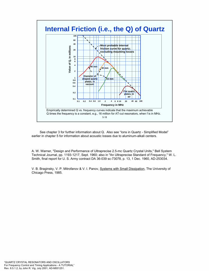
“QUARTZ CRYSTAL RESONATORS AND OSCILLATORSFor Frequency Control and Timing Applications - A TUTORIAL”Rev. 8.5.1.2, by John R. Vig, July 2001, AD-M001251.
5-18
Empirically determined Q vs. frequency curves indicate that the maximum achievable Q times the frequency is a constant, e.g., 16 million for AT-cut resonators, when f is in MHz.
100
60
40
20
1086
4
2
10.80.6
0.4
0.2
0.10.1 0.2 0.4 0.6 1.0 2 4 6 8 10 20 40 60 100
Valu
e of
Q, i
n m
illio
n s
Frequency in MHz
Most probable internalfriction curve for quartz;excluding mounting losses
Diameter of shaped quartz
plates, in vacuum
90 mm 30 mm
15 mm
Flat quartz plates, in
air
Internal Friction (i.e., the Q) of Quartz
See chapter 3 for further information about Q. Also see “Ions in Quartz - Simplified Model”earlier in chapter 5 for information about acoustic losses due to aluminum-alkali centers.
A. W. Warner, "Design and Performance of Ultraprecise 2.5-mc Quartz Crystal Units," Bell System Technical Journal, pp. 1193-1217, Sept. 1960; also in "An Ultraprecise Standard of Frequency," W. L. Smith, final report for U. S. Army contract DA 36-039 sc-73078, p. 13, 1 Dec. 1960, AD-253034.
V. B. Braginsky, V. P. Mitrofanov & V. I. Panov, Systems with Small Dissipation, The University of Chicago Press, 1985.
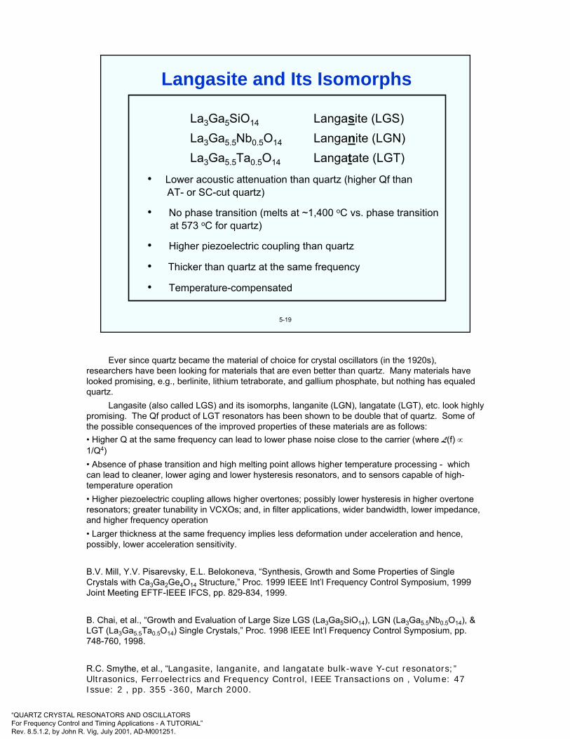
“QUARTZ CRYSTAL RESONATORS AND OSCILLATORSFor Frequency Control and Timing Applications - A TUTORIAL”Rev. 8.5.1.2, by John R. Vig, July 2001, AD-M001251.
5-19
La3Ga5SiO14 Langasite (LGS)La3Ga5.5Nb0.5O14 Langanite (LGN)La3Ga5.5Ta0.5O14 Langatate (LGT)
• Lower acoustic attenuation than quartz (higher Qf than AT- or SC-cut quartz)
• No phase transition (melts at ~1,400 oC vs. phase transition at 573 oC for quartz)
• Higher piezoelectric coupling than quartz
• Thicker than quartz at the same frequency
• Temperature-compensated
Langasite and Its Isomorphs
Ever since quartz became the material of choice for crystal oscillators (in the 1920s), researchers have been looking for materials that are even better than quartz. Many materials have looked promising, e.g., berlinite, lithium tetraborate, and gallium phosphate, but nothing has equaled quartz.
Langasite (also called LGS) and its isomorphs, langanite (LGN), langatate (LGT), etc. look highly promising. The Qf product of LGT resonators has been shown to be double that of quartz. Some of the possible consequences of the improved properties of these materials are as follows:• Higher Q at the same frequency can lead to lower phase noise close to the carrier (where L(f) ∝1/Q4)• Absence of phase transition and high melting point allows higher temperature processing - which can lead to cleaner, lower aging and lower hysteresis resonators, and to sensors capable of high-temperature operation• Higher piezoelectric coupling allows higher overtones; possibly lower hysteresis in higher overtone resonators; greater tunability in VCXOs; and, in filter applications, wider bandwidth, lower impedance, and higher frequency operation• Larger thickness at the same frequency implies less deformation under acceleration and hence, possibly, lower acceleration sensitivity.
B.V. Mill, Y.V. Pisarevsky, E.L. Belokoneva, “Synthesis, Growth and Some Properties of Single Crystals with Ca3Ga2Ge4O14 Structure,” Proc. 1999 IEEE Int’l Frequency Control Symposium, 1999 Joint Meeting EFTF-IEEE IFCS, pp. 829-834, 1999.
B. Chai, et al., “Growth and Evaluation of Large Size LGS (La3Ga5SiO14), LGN (La3Ga5.5Nb0.5O14), & LGT (La3Ga5.5Ta0.5O14) Single Crystals,” Proc. 1998 IEEE Int’l Frequency Control Symposium, pp. 748-760, 1998.
R.C. Smythe, et al., “Langasite, langanite, and langatate bulk-wave Y-cut resonators;”Ultrasonics, Ferroelectrics and Frequency Control, IEEE Transactions on , Volume: 47 Issue: 2 , pp. 355 -360, March 2000.
“QUARTZ CRYSTAL RESONATORS AND OSCILLATORSFor Frequency Control and Timing Applications - A TUTORIAL”Rev. 8.5.1.2, by John R. Vig, July 2001, AD-M001251.
* There are two important reasons for including this chapter: 1. atomic frequency standards are one of the most important applications of precision quartz oscillators, and 2. those who study or use crystal oscillators ought to be aware of what is available in case they need an oscillator with better long-term stability than what crystal oscillators can provide.
6
CHAPTER 6Atomic Frequency Standards*
General References
H. Hellwig, "Frequency Standards and Clocks: A Tutorial Introduction," NBS Technical Note 616, 1977, Time and Frequency Division, NIST, 325 Broadway, Boulder, Colorado, 80303.
H. Hellwig, "Microwave Frequency and Time Standards," in E. A. Gerber and A. Ballato, Precision Frequency Control, Vol. 2, pp. 113-176, Academic Press, 1985.
H. Hellwig, "Microwave Time and Frequency Standards," Radio Science, Vol. 14, No. 4, pp. 561-572, July-August 1979.
F. G. Major, The Quantum Beat - The Physical Principles of Atomic Clocks, Springer-Verlag, 1998.
J. Vanier and C. Audoin, The Quantum Physics of Atomic Frequency Standards, ISBN 0-85274-434-X, Adam Hilger, 1978.
S. R. Stein and J. R. Vig, "Frequency Standards for Communications," U. S. Army Laboratory Command Research and Development Technical Report SLCET-TR-91-2 (Rev. 1), October 1991, AD-A243211. This report is a reprint of a chapter "Communications Frequency Standards," in The Froehlich/Kent Encyclopedia of Telecommunications, Vol. 3, pp. 445-500, Marcel Dekker, Inc., 1992.
L. L. Lewis, “An Introduction to Frequency Standards,” Proc. IEEE, vol. 79, pp. 927-935, 1991.
N. F. Ramsey, Molecular Beams, Oxford University Press, 1956.
P. Forman, "Atomichron: The Atomic Clock from Concept to Commercial Product," Proc. of the IEEE, Vol. 73, No. 7, pp. 1181-1204, July 1985.
Several review papers, including three on the environmental sensitivities of atomic frequency standards, are contained in the Proc. 22nd Ann. Precise Time and Time Interval (PTTI) Applications and Planning Meeting, NASA Conference Publ. 3116, 1990; AD-A239372.
Proceedings of the IEEE, Special Issue on Time and Frequency, J. Jespersen & D. W. Hanson, ed's., Vol. 79, No. 7, July 1991.
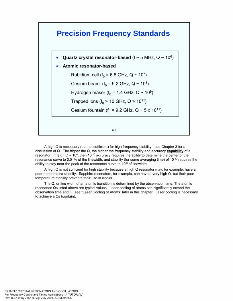
“QUARTZ CRYSTAL RESONATORS AND OSCILLATORSFor Frequency Control and Timing Applications - A TUTORIAL”Rev. 8.5.1.2, by John R. Vig, July 2001, AD-M001251.
6-1
• Quartz crystal resonator-based (f ~ 5 MHz, Q ~ 106)
• Atomic resonator-based
Rubidium cell (f0 = 6.8 GHz, Q ~ 107)
Cesium beam (f0 = 9.2 GHz, Q ~ 108)
Hydrogen maser (f0 = 1.4 GHz, Q ~ 109)
Trapped ions (f0 > 10 GHz, Q > 1011)
Cesium fountain (f0 = 9.2 GHz, Q ~ 5 x 10¹¹)
Precision Frequency Standards
A high Q is necessary (but not sufficient) for high frequency stability - see Chapter 3 for a discussion of Q. The higher the Q, the higher the frequency stability and accuracy capability of a resonator. If, e.g., Q = 106, then 10-10 accuracy requires the ability to determine the center of the resonance curve to 0.01% of the linewidth, and stability (for some averaging time) of 10-12 requires the ability to stay near the peak of the resonance curve to 10-6 of linewidth.
A high Q is not sufficient for high stability because a high Q resonator may, for example, have a poor temperature stability. Sapphire resonators, for example, can have a very high Q, but their poor temperature stability prevents their use in clocks.
The Q, or line width of an atomic transition is determined by the observation time. The atomic resonance Qs listed above are typical values. Laser cooling of atoms can significantly extend the observation time and Q (see “Laser Cooling of Atoms” later in this chapter. Laser cooling is necessary to achieve a Cs fountain).

“QUARTZ CRYSTAL RESONATORS AND OSCILLATORSFor Frequency Control and Timing Applications - A TUTORIAL”Rev. 8.5.1.2, by John R. Vig, July 2001, AD-M001251.
6-2
When an atomic system changes energy from an exited state to a lower energy state, a photon is emitted. The photon frequency ν is given by Planck’s law
where E2 and E1 are the energies of the upper and lower states, respectively, and h is Planck’s constant. An atomic frequency standard produces an output signal the frequency of which is determined by this intrinsic frequency rather than by the properties of a solid object and how it is fabricated (as it is in quartz oscillators).
The properties of isolated atoms at rest, and in free space, would not change with space and time. Therefore, the frequency of an ideal atomic standard would not change with time or with changes in the environment. Unfortunately, in real atomic frequency standards: 1) the atoms are moving at thermal velocities, 2) the atoms are not isolated but experience collisions and electric and magnetic fields, and 3) some of the components needed for producing and observing the atomic transitions contribute to instabilities.
hEE 12 −
=ν
Atomic Frequency Standard Basic Concepts
Atomic frequency standards must be understood in terms of the concepts of quantum mechanics. The properties of simple atomic systems cannot assume arbitrary values. For example, the energies of the bound states of an atomic system are constrained to discrete values called energy levels. When an atomic system changes energy from an excited state to a state with lower energy, it emits a quantity of electromagnetic energy called a photon, the frequency of which is determined by the energy difference between the two states, in accordance with Planck’s law, shown above.
Atomic systems can be isolated from unwanted perturbations, which result in small sensitivities to temperature, pressure, and other environmental conditions. The low level of interaction also results in extremely sharp resonance features, and reduces errors due to imperfections in the electronics. All atoms of an element are identical, and atomic properties are time invariant, which makes it possible to build very stable devices.
Atomic frequency standards are categorized in several ways; most often, they are referred to by the type of atom: hydrogen, rubidium, or cesium. Actually, these three devices are based on the same type of atomic interaction, but there are great practical differences in their implementation. Some atomic frequency standards, called oscillators, are active, in which case the output signal is derived from the radiation emitted by the atom. Others are passive; the atoms are then employed as a discriminator to measure and control the frequency of an electronic oscillator, such as a quartz oscillator. The third classification follows the method of interaction. In atomic beams, the atoms are observed "on the fly"; they pass through the interaction region and are not used again. In contrast, storage devices contain some type of cell that holds the atoms to be observed indefinitely (ideally).
S. R. Stein and J. R. Vig, "Frequency Standards for Communications," U. S. Army Laboratory Command Research and Development Technical Report SLCET-TR-91-2 (Rev. 1), October 1991, AD-A243211. This report is a reprint of a chapter, "Communications Frequency Standards," in The Froehlich/Kent Encyclopedia of Telecommunications, Vol. 3, pp. 445-500, Marcel Dekker, Inc., 1992.

“QUARTZ CRYSTAL RESONATORS AND OSCILLATORSFor Frequency Control and Timing Applications - A TUTORIAL”Rev. 8.5.1.2, by John R. Vig, July 2001, AD-M001251.
6-3
Hydrogen-like (or alkali)atoms
Hyperfine structure of 87Rb, with nuclear spin I=3/2, ν0=∆W/h=6,834,682,605 Hz and X=[(-µJ/J) +(µI/I)]H0/∆W
calibrated in units of 2.44 x 10³ Oe.
S
NNuclearspin and
dipole
Electronspin and
dipole
N
Closedelectronic
shell
ElectronS
3
2
1
-1
-2
-3
2 3 4 X
MF =210-1
MF =-2-101
F=2
F=1
∆W
NucleusElectron
Hydrogen-Like Atoms
All commercial atomic frequency standards are based on hyperfine transitions of one of three hydrogen-like atoms, rubidium, cesium and hydrogen.
The energy levels of an atom are generally classified according to their physical origin. For example, the principal levels of an atom are associated with the radius of the "orbit" of an electron about the nucleus. These levels have the largest atomic energy separations. The principal energy levels are subdivided as a result of the quantization of the angular momentum of the atom. The angular momentum due to the motion of a particle, such as an electron, is called orbital angular momentum. Even when their motion is such that there is no orbital angular momentum, atomic particles may possess an intrinsic angular momentum or spin and a proportional intrinsic magnetic moment. The principal levels are first divided according to the shape of the electron "orbits." Still finer division occurs as a consequence of the particular orientation of the electron's spin and the spin of the nucleus.
The photons emitted when atoms change states among the principal energy levels are usually in the infrared and higher energy regions of the electromagnetic spectrum. The frequencies of these energetic photons are too high for practical electronic devices. Atomic frequency standards are feasible because of the splitting of the ground state of the atom. Next lower, in terms of energy, is the fine structure of the atom, which results from the interaction of the spin of the electron with the magnetic field due to the motion of the electron through the nuclear electric field. This structure is thousands of times smaller than the separation of the principal energy levels. Laboratory atomic frequency standards based on fine structure in calcium and magnesium have been built, but the fundamental frequencies of the atomic transitions are higher than 600 GHz, which is difficult to synthesize.
A finer energy splitting than the spin-orbit coupling is produced by the interaction of the electron and nuclear spins; this is called the hyperfine structure. The ground state of a hydrogen-like atom (e.g., H, Li, Na, K, Rb, Cs, and singly ionized Be) has a single unpaired electron in a symmetric orbit. In this case, there is no orbital angular momentum and no fine structure. The energy splitting due to the intrinsic magnetic moments of the electron and the nucleus can be a million times smaller than the separation of the principal energy levels. The transition frequencies are convenient: 1.4 GHz for hydrogen, 6.8 GHz for rubidium, and 9.2 GHz for cesium.
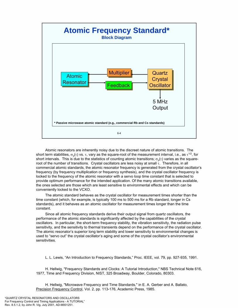
“QUARTZ CRYSTAL RESONATORS AND OSCILLATORSFor Frequency Control and Timing Applications - A TUTORIAL”Rev. 8.5.1.2, by John R. Vig, July 2001, AD-M001251.
6-4
AtomicResonatorAtomic
ResonatorFeedbackFeedback
MultiplierMultiplier QuartzCrystal
Oscillator
QuartzCrystal
Oscillator
5 MHzOutput
Atomic Frequency Standard*Block Diagram
* Passive microwave atomic standard (e.g., commercial Rb and Cs standards)
Atomic resonators are inherently noisy due to the discreet nature of atomic transitions. The short term stabilities, σy(τ) vs. τ, vary as the square-root of the measurement interval, i.e., as τ1/2, for short intervals. This is due to the statistics of counting atomic transitions; σy(τ) varies as the square-root of the number of transitions. Crystal oscillators are less noisy at small τ. Therefore, in all commercial atomic standards, the atomic resonator frequency is generated from the crystal oscillator’s frequency (by frequency multiplication or frequency synthesis), and the crystal oscillator frequency is locked to the frequency of the atomic resonator with a servo loop time constant that is selected to provide optimum performance for the intended application. Of the many atomic transitions available, the ones selected are those which are least sensitive to environmental effects and which can be conveniently locked to the VCXO.
The atomic standard behaves as the crystal oscillator for measurement times shorter than the time constant (which, for example, is typically 100 ms to 500 ms for a Rb standard, longer in Cs standards), and it behaves as an atomic oscillator for measurement times longer than the time constant.
Since all atomic frequency standards derive their output signal from quartz oscillators, the performance of the atomic standards is significantly affected by the capabilities of the crystal oscillators. In particular, the short-term frequency stability, the vibration sensitivity, the radiation pulse sensitivity, and the sensitivity to thermal transients depend on the performance of the crystal oscillator. The atomic resonator’s superior long term stability and lower sensitivity to environmental changes is used to “servo out” the crystal oscillator’s aging and some of the crystal oscillator’s environmental sensitivities.
L. L. Lewis, “An Introduction to Frequency Standards,” Proc. IEEE, vol. 79, pp. 927-935, 1991.
H. Hellwig, "Frequency Standards and Clocks: A Tutorial Introduction," NBS Technical Note 616, 1977, Time and Frequency Division, NIST, 325 Broadway, Boulder, Colorado, 80303.
H. Hellwig, "Microwave Frequency and Time Standards," in E. A. Gerber and A. Ballato, Precision Frequency Control, Vol. 2, pp. 113-176, Academic Press, 1985.

“QUARTZ CRYSTAL RESONATORS AND OSCILLATORSFor Frequency Control and Timing Applications - A TUTORIAL”Rev. 8.5.1.2, by John R. Vig, July 2001, AD-M001251.
6-5
Prepare AtomicState
Prepare AtomicState
ApplyMicrowaves
ApplyMicrowaves
Detect AtomicState Change
Detect AtomicState Change
Tune Microwave FrequencyFor Maximum State ChangeTune Microwave FrequencyFor Maximum State Change
B
0hνA
Generalized Microwave Atomic Resonator
• Let A and B be two possible energy states of an atom, separated by energy hνo; then νois the frequency of the electromagnetic radiation required to convert the atoms from A to B, or from B to A; νo is in the microwave range for all currently manufactured atomicstandards.
• Population difference between energy states, when hνo << kT, is near zero. Therefore, in a natural ensemble of atoms, when νo is applied, about half the atoms absorb hνo and half emit hνo; the net effect is zero.
• A nonthermal distribution is prepared, i.e., one of the states is "selected," by optical excita-tion from one of the levels to a third level or by magnetic deflection of an atomic beam.
• Microwave energy is absorbed in the process of converting the selected atoms to the other energy state, e.g., from A to B. Thus, the applied microwave frequency can be "locked" to the frequency corresponding to the atomic transition.
The microwave signals that interrogate the atoms are generally modulated at audio frequencies. Phase sensitive detection of the atomic signal is used to adjust the frequency of the crystal oscillator to the frequency that produces the maximum atomic signal.
L. L. Lewis, “An Introduction to Frequency Standards,” Proc. IEEE, vol. 79, pp. 927-935, 1991.

“QUARTZ CRYSTAL RESONATORS AND OSCILLATORSFor Frequency Control and Timing Applications - A TUTORIAL”Rev. 8.5.1.2, by John R. Vig, July 2001, AD-M001251.
6-6
• The energy levels used are due to the spin-spin interaction between the atomic nucleus andthe outer electron in the ground state (2S1/2) of the atom; i.e., the ground state hyperfinetransitions.
• Nearly all atomic standards use Rb or Cs atoms; nuclear spins I = 3/2 and 7/2, respectively.
• Energy levels split into 2(I ± 1/2)+1 sublevels in a magnetic field; the "clock transition" is thetransition between the least magnetic-field-sensitive sublevels. A constant magnetic field, the"C-field," is applied to minimize the probability of the more magnetic-field-sensitive transitions.
• Magnetic shielding is used to reduce external magnetic fields (e.g., the earth's) at least 100-fold.
• The Heisenberg uncertainty principle limits the achievable accuracy: ∆E∆t ≥ h/2π, E = hν,therefore, ∆ν∆t ≥1, and, long observation time → small frequency uncertainty.
• Resonance linewidth (i.e., 1/Q) is inversely proportional to coherent observation time ∆t; ∆t islimited by: 1.) when atom enters and leaves the apparatus, and 2.) when the atom stops oscillating due to collisions with other atoms or with container walls (collisions disturb atom's electronic structure).
• In microwave atomic standards, as atoms move with respect to the microwave source, resonance frequency is shifted due to the Doppler effect (k•v); velocity distribution results in "Doppler broadening"; the second-order Doppler shift (1/2 v2/c2) is due to relativistic time dilation.
Atomic Resonator Concepts
F. G. Major, The Quantum Beat - The Physical Principles of Atomic Clocks, Springer-Verlag, 1998.J. Vanier and C. Audoin, The Quantum Physics of Atomic Frequency Standards, ISBN 0-85274-434-X, Adam Hilger, 1978.

“QUARTZ CRYSTAL RESONATORS AND OSCILLATORSFor Frequency Control and Timing Applications - A TUTORIAL”Rev. 8.5.1.2, by John R. Vig, July 2001, AD-M001251.
6-7
Energy level diagrams of 85Rb and 87Rb
F = 3F = 2 363 MHz 816 MHz
F = 2
F = 152P1/2
85Rb 87Rb
795 nm 795 nm
F = 3 F = 2
F = 2
3.045 GHz
52S1/2
F = 1
6.834,682,608 GHz
Rubidium Cell Frequency Standard
Referring back to “Generalized Atomic Resonator” earlier in this chapter, the A and B levels for a rubidium standard are the energy levels between the 87Rb F = 1 and F = 2 hyperfine levels of the 52S1/2ground states. The difference in the energies of those two levels correspond to 6.834,682,608 GHz, which is the atomic resonance frequency utilized in rubidium standards. Initially, about an equal number of atoms are in the two ground states. A nonthermal distribution can be prepared by optical pumping to a third level, the F = 1 excited state of 87Rb, as follows.
A 87Rb discharge lamp emits wavelengths that can pump both the A and B levels to the F = 1 excited state. However, due to the natural coincidence of optical resonance frequencies between 85Rb and 87Rb, both of which correspond to a 795 nm wavelength, a 85Rb filter cell can filter the wavelength corresponding to the transition from the F = 2 ground state of 87Rb. Assuming a perfect filter, the filtered light pumps atoms only from the F = 1 ground state to the excited state, not from the F = 2 ground state. The 87Rb atoms remain in the excited state for a short time only; they emit a photon and return (with about equal probability) to either the A or B ground states. If they return to A, they will be pumped again to the excited state, if they return to B, they will not be pumped. Eventually, all the atoms end up in the level B (F = 2 ground) state. Light from the discharge lamp then passes through the absorption cell without attenuation.
If 6.834,682,608 GHz microwave energy is applied to the atoms, the atoms in level B return to level A (via a spin-flip; see “Hydrogen-Like Atoms,” earlier in this chapter), light is absorbed as the level A atoms are optically pumped, and this light attenuation can be sensed with a photodetector. The microwave frequency can, thereby, be controlled by the dip in the photodetector output, which occurs only when the microwave frequency is at the 6.834,682,608 GHz atomic resonance frequency. When the microwave frequency starts to drift, the change in photodetector output brings the frequency back to the proper frequency, i.e., the microwave frequency is locked to the atomic resonance frequency.
The apparatus that can make all this happen is shown schematically on the next page.
L. L. Lewis, “An Introduction to Frequency Standards,” Proc. IEEE, vol. 79, pp. 927-935, 1991.
H. Hellwig, "Microwave Frequency and Time Standards," in E. A. Gerber and A. Ballato, Precision Frequency Control, Vol. 2, pp. 113-176, Academic Press, 1985.

“QUARTZ CRYSTAL RESONATORS AND OSCILLATORSFor Frequency Control and Timing Applications - A TUTORIAL”Rev. 8.5.1.2, by John R. Vig, July 2001, AD-M001251.
6-8
Atomic resonator schematic diagram
Magnetic shield
“C-Field” Absorptioncell
87Rblamp
rflamp
exciter
Power suppliesfor lamp, filterand absorptioncell thermostats
FilterCell
85Rb+ buffer
gas
Cavity
Photocell
Detectoroutput
C-fieldpowersupply
Frequencyinput
6.834,685 GHz
Rb-87+ buffer
gasLight
Rubidium Cell Frequency Standard
Light from the 87Rb (rf discharge) lamp passes through the 85Rb filter cell and into the absorption cell, which contains 87Rb gas plus a buffer gas. The 87Rb lamp emits wavelengths corresponding to both the 87Rb F = 1 and F = 2 transitions. The 85Rb filter cell absorbs more of the F=2 transition light. The light which passes through the filter cell is absorbed by the 87Rb F=1 state, the excited atoms relax to both the F=1 and F=2 states, but the F=1 states are excited again; the F=2 state is overpopulated; the applied 6.8 GHz microwave converts F=2 back to F=1, which provides more atoms to absorb light. The microwave at the correct resonance frequency causes increased light absorption, i.e., a (< 1%) dip, in the light detected by the photocell. The microwave frequency is locked to photocell detection dip, thus the atomic transition frequency controls the microwave frequency, i.e., the frequency of the crystal oscillator.
The absorption cell contains Rb gas at ~10-6 torr and an inert buffer gas at ~1 torr. The Rb atom oscillation lifetime is limited by collisions to ~10-2 s; the atomic resonance linewidth ~100 Hz; Q ~5 x 10⁷. The buffer gas, a mixture of positive (e.g., N2) and negative (e.g., Ar) pressure-shift gases, provides zero temperature coefficient at some temperature in the operating temperature range, and confines Rb atoms to a small region to reduce wall-collisions and first order Doppler effects.
F. G. Major, The Quantum Beat - The Physical Principles of Atomic Clocks, Springer-Verlag, 1998.
J. Vanier and C. Audoin, The Quantum Physics of Atomic Frequency Standards, ISBN 0-85274-434-X, Adam Hilger, 1978.

“QUARTZ CRYSTAL RESONATORS AND OSCILLATORSFor Frequency Control and Timing Applications - A TUTORIAL”Rev. 8.5.1.2, by John R. Vig, July 2001, AD-M001251.
6-9
9.2
0Ener
gy (F
requ
ency
) (G
Hz)
Magnetic Field HO Energy statesat H = HO
(F, mF)(4,4)(4,3)(4,2)(4,1)(4,0)(4,-1)(4,-2)(4,-3)(4,-4)
(3,-3)(3,-2)(3,-1)(3,0)(3,1)(3,2)(3,3)
9.192,631,770 GHz
Cs Hyperfine Energy Levels
Shown are the magnetic field dependence of the hyperfine energy levels in the ground state of the cesium atom (nine in the upper state, seven in the lower). The magnetic field is plotted up to the value HO. The solid arrow represents the “clock” transition; the dashed arrows depict the magnetic-field-sensitive (Zeeman) transitions. F is the hyperfine quantum number, and mF is the magnetic quantum number of the atom. The atomic resonance utilized is at 9,192,631,770 Hz - by definition (of the second*), which corresponds to the (3,0) to (4,0) hyperfine transition, called the clock transition. Referring back to “Generalized Atomic Resonator” earlier in this chapter, the (3,0) and (4,0) levels are the A and B levels.
This (3,0) to (4,0) transition has a small quadratic dependence on magnetic field. The C-field must be stable and uniform; high degree of shielding is required for ±1x10-13/gauss magnetic field sensitivity (e.g., one laboratory Cs standard uses a triple magnetic shield).
It would be desirable to operate at zero magnetic field - all transitions would then behave as a single transition, the signal would be 7X larger, but that would require < 10-8 gauss for errors < 1 x 10-
12. This is not feasible; a C-field must be applied. A 0.06 gauss C-field separates the sublevels by 40 kHz, and the the (3,0) and (4,0) levels, the level with the minimum magnetic field sensitivity are utilized in making a Cs frequency standard. The way these levels are utilized is shown schematically on the next two pages.
See “Magnetic Field Sensitivities of Atomic Clocks” later in this chapter.
* See “The Second” in chapter 8.

“QUARTZ CRYSTAL RESONATORS AND OSCILLATORSFor Frequency Control and Timing Applications - A TUTORIAL”Rev. 8.5.1.2, by John R. Vig, July 2001, AD-M001251.
Atomic state selection Cs atom detection
ATOMIC BEAMSOURCE
ATOMIC BEAM
Cs VAPOR, CONTAINING AN EQUALAMOUNT OF THE TWOKINDS OF Cs ATOMS
VACUUM CHAMBER
MAGNET(STATE SELECTOR)
N
S
KIND 1 - ATOMS(LOWER STATE)
KIND 2 - ATOMS(UPPER STATE)
DETECTOR
DETECTOR
MAXIMUM SIGNAL
NO SIGNAL
S
S
N
N
MAGNET
MAGNET
MICROWAVECAVITY
MICROWAVECAVITY
MICROWAVE SIGNAL(OF ATOMIC RESONANCEFREQUENCY)
STATE SELECTEDATOMIC BEAM
STATE SELECTEDATOMIC BEAM
NO SIGNAL
6-10
Cesium-Beam Frequency Standard
A Cs vapor is generated in the oven, the atoms are collimated, and the beam of Cs atoms are directed to pass through a strongly diverging field of the “A” magnet, the “state-selector” magnet. The force on an atom of magnetic moment µi in a magnetic field B is
Fi = -µi (∇•B)
Therefore, the atoms are deflected by amounts that depend on their magnetic moments, i.e., their energy states. The atoms in the (3,0) state are deflected in a different direction than those in the (4,0) state. In this manner, the two types of atoms can be physically separated. The (3,0) and (4,0) levels are the A and B levels, referring back to “Generalized Atomic Resonator” earlier in this chapter,
The state selecting magnet "selects" one of the two atomic levels. The applied microwave at the atomic resonance frequency causes a state change (a spin-flip; see “Hydrogen-Like Atoms,” earlier in this chapter); the second magnet deflects those atoms to the detector which have undergone the state change. The magnets' peak field is ~10 kgauss.
The atom detector is a ribbon or wire (e.g., W or Pt) at ~ 900°C. The Cs atoms are ionized, the ions are collected, the current is amplified and fed back into feedback network. In this way, the microwave frequency is locked to the frequency of maximum ion current, thus the atomic transition frequency controls the microwave frequency, i.e., the frequency of the crystal oscillator.
Much less than 1% of the Cs atoms reach the detector in conventional Cs standards (hence optical pumping's advantage - see “Optically Pumped Cs Standard” later in this chapter.)
F. G. Major, The Quantum Beat - The Physical Principles of Atomic Clocks, Springer-Verlag, 1998.
J. Vanier and C. Audoin, The Quantum Physics of Atomic Frequency Standards, ISBN 0-85274-434-X, Adam Hilger, 1978.
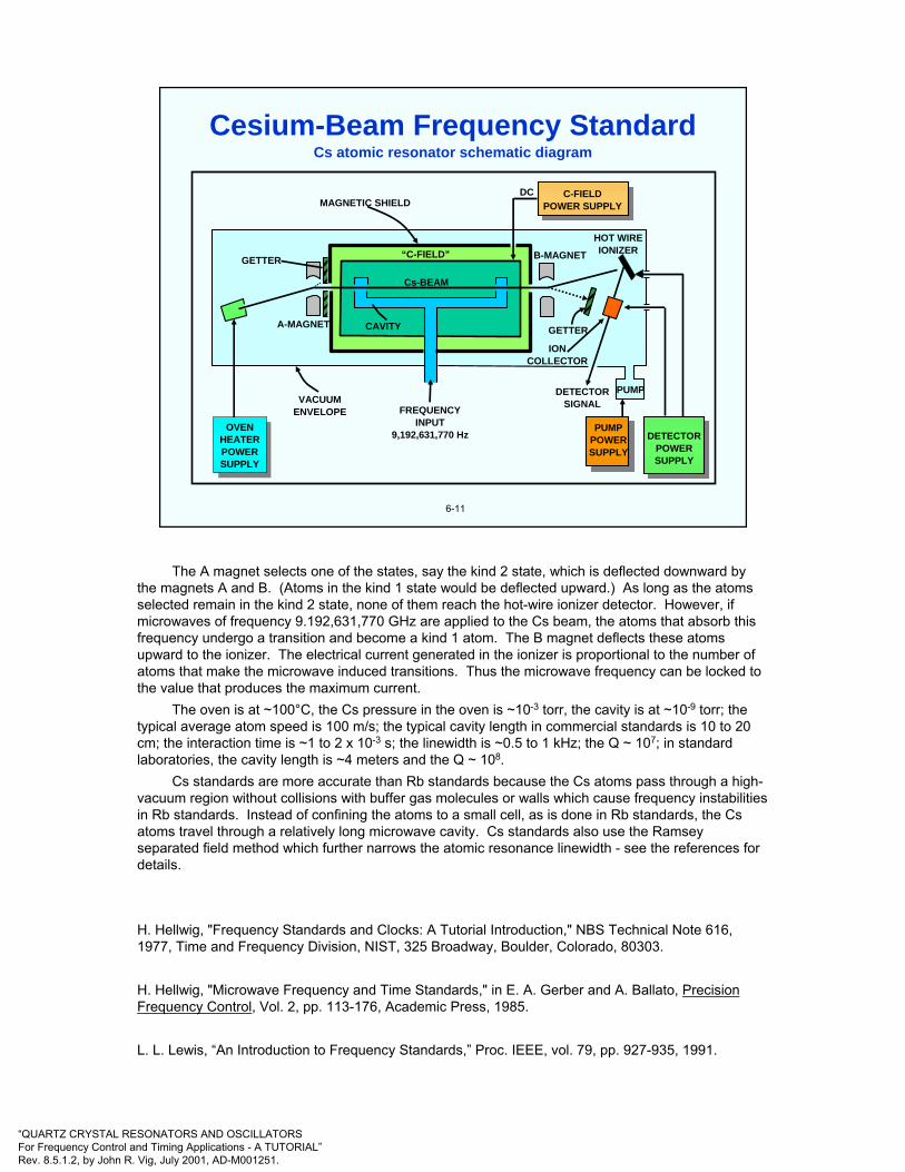
“QUARTZ CRYSTAL RESONATORS AND OSCILLATORSFor Frequency Control and Timing Applications - A TUTORIAL”Rev. 8.5.1.2, by John R. Vig, July 2001, AD-M001251.
Cs atomic resonator schematic diagram
6-11
HOT WIREIONIZERB-MAGNET
GETTER
IONCOLLECTOR
PUMPDETECTORSIGNAL
PUMPPOWERSUPPLY
DETECTORPOWERSUPPLY
C-FIELDPOWER SUPPLY
DCMAGNETIC SHIELD
“C-FIELD”
Cs-BEAM
CAVITY
FREQUENCYINPUT
9,192,631,770 Hz
VACUUMENVELOPE
OVENHEATERPOWERSUPPLY
OVENHEATERPOWERSUPPLY
A-MAGNET
GETTER
Cesium-Beam Frequency Standard
The A magnet selects one of the states, say the kind 2 state, which is deflected downward by the magnets A and B. (Atoms in the kind 1 state would be deflected upward.) As long as the atoms selected remain in the kind 2 state, none of them reach the hot-wire ionizer detector. However, if microwaves of frequency 9.192,631,770 GHz are applied to the Cs beam, the atoms that absorb this frequency undergo a transition and become a kind 1 atom. The B magnet deflects these atoms upward to the ionizer. The electrical current generated in the ionizer is proportional to the number of atoms that make the microwave induced transitions. Thus the microwave frequency can be locked to the value that produces the maximum current.
The oven is at ~100°C, the Cs pressure in the oven is ~10-3 torr, the cavity is at ~10-9 torr; the typical average atom speed is 100 m/s; the typical cavity length in commercial standards is 10 to 20 cm; the interaction time is ~1 to 2 x 10⁻³ s; the linewidth is ~0.5 to 1 kHz; the Q ~ 107; in standard laboratories, the cavity length is ~4 meters and the Q ~ 108.
Cs standards are more accurate than Rb standards because the Cs atoms pass through a high-vacuum region without collisions with buffer gas molecules or walls which cause frequency instabilities in Rb standards. Instead of confining the atoms to a small cell, as is done in Rb standards, the Cs atoms travel through a relatively long microwave cavity. Cs standards also use the Ramsey separated field method which further narrows the atomic resonance linewidth - see the references for details.
H. Hellwig, "Frequency Standards and Clocks: A Tutorial Introduction," NBS Technical Note 616, 1977, Time and Frequency Division, NIST, 325 Broadway, Boulder, Colorado, 80303.
H. Hellwig, "Microwave Frequency and Time Standards," in E. A. Gerber and A. Ballato, Precision Frequency Control, Vol. 2, pp. 113-176, Academic Press, 1985.
L. L. Lewis, “An Introduction to Frequency Standards,” Proc. IEEE, vol. 79, pp. 927-935, 1991.

“QUARTZ CRYSTAL RESONATORS AND OSCILLATORSFor Frequency Control and Timing Applications - A TUTORIAL”Rev. 8.5.1.2, by John R. Vig, July 2001, AD-M001251.
6-12
W
H’
(F, mF)
(1, +1)
(1, 0)
(1, -1)
(0, 0)
Ground state energy levels of atomic hydrogen as a function of magnetic field H’.
1.42040…GHz
Atomic Hydrogen Energy Levels
The above figure shows the relevant energy levels of a hydrogen atom in a magnetic field. The hydrogen maser (H-maser) operates on the nearly field independent (at low fields) hyperfine transition between the (1,0) and (0,0) states. The energy difference between these two states corresponds to a 1,420,405,752 Hz frequency (21 cm wavelength).
There are two types of hydrogen masers, active and passive. In the active maser, the 1.42 GHz output signal is obtained directly from stimulated radiation by the H atoms (“maser” was originally an abbreviation for microwave amplification by stimulated emission of radiation). In the passive H-maser, as in all passive atomic standards, a microwave oscillator stimulates the desired atomic transitions and a control loop provides feedback to tune a quartz oscillator to the frequency that maximizes the transition rate.
H. Hellwig, "Microwave Frequency and Time Standards," in E. A. Gerber and A. Ballato, Precision Frequency Control, Vol. 2, pp. 113-176, Academic Press, 1985.
L. L. Lewis, “An Introduction to Frequency Standards,” Proc. IEEE, vol. 79, pp. 927-935, 1991.

“QUARTZ CRYSTAL RESONATORS AND OSCILLATORSFor Frequency Control and Timing Applications - A TUTORIAL”Rev. 8.5.1.2, by John R. Vig, July 2001, AD-M001251.
6-13
Microwaveoutput
Teflon coatedstorage bulb
Microwavecavity
Microwaveinput
State selector
Hydrogenatoms
Passive H-Maser Schematic Diagram
In a H-maser, molecular hydrogen is dissociated by an electrical discharge, and the resulting atomic hydrogen is collimated into a beam. As is done in the Cs standard, an inhomogeneous magnetic field is used to separate, i.e., “state-select,” atomic states. The maser cavity is coated with Teflon to minimize atomic perturbations due to collisions with the cavity wall.
A frequency modulated 1.42…GHz microwave signal is passed through the cavity to interrogate the atoms. As the microwaves induce atomic transitions, the atoms emit 1.42…GHz radiation. In active masers, this 1.42…GHz is detected and is used directly. In passive standards, the applied modulated microwave signal interacts with the atomic resonance line’s frequency. A phase shift of the carrier frequency results, as well as an AM signal at the modulation frequency which is proportional to the offset of the carrier frequency from the atomic resonance frequency. The AM is detected and is used to tune a quartz oscillator so that the center of the carrier frequency coincides with the atomic resonance frequency.
Because of their superior resonance line Q (~109), H-masers have short term stabilities that are superior to those of Cs and Rb standards. Stabilities of <10-15 at the noise floor and <10-14 at one day have been reported. H-masers are the principal clocks used for radio astronomy, where the clocks must stay coherent to a small fraction of a radio frequency cycle during the observation period (minutes to hours). The large size of most hydrogen masers (typical active hydrogen masers are ten times the volume of commercial Cs frequency standards) results from the 1.4 GHz microwave cavity and the surrounding layers of magnetic shielding and temperature-stabilizing ovens. Hydrogen masers are not primary standards; they typically exhibit frequency aging of 1 to 10 X 10-12 per year.
H. Hellwig, "Microwave Frequency and Time Standards," in E. A. Gerber and A. Ballato, Precision Frequency Control, Vol. 2, pp. 113-176, Academic Press, 1985.
S. R. Stein and J. R. Vig, "Frequency Standards for Communications," U. S. Army Laboratory Command Research and Development Technical Report SLCET-TR-91-2 (Rev. 1), October 1991, AD-A243211. This report is a reprint of a chapter "Communications Frequency Standards," in The Froehlich/Kent Encyclopedia of Telecommunications, Vol. 3, pp. 445-500, Marcel Dekker, Inc., 1992.
T. E. Parker, “Environmental Factors and Hydrogen Maser Frequency Stability,” IEEE Trans. UFFC, vol. 46, pp. 745-751, 1999.

“QUARTZ CRYSTAL RESONATORS AND OSCILLATORSFor Frequency Control and Timing Applications - A TUTORIAL”Rev. 8.5.1.2, by John R. Vig, July 2001, AD-M001251.
6-14
• Noise - due to the circuitry, crystal resonator, and atomic resonator. (See nextpage.)
• Cavity pulling - microwave cavity is also a resonator; atoms and cavity behave as two coupled oscillators; effect can be minimized by tuning the cavity to the atomic resonance frequency, and by maximizing the atomic resonance Q to cavity Q ratio.
• Collisions - cause frequency shifts and shortening of oscillation duration.
• Doppler effects - 1st order is classical, can be minimized by design; 2nd order is relativistic; can be minimized by slowing the atoms via laser cooling - see“Laser Cooling of Atoms” later in this chapter.
• Magnetic field - this is the only influence that directly affects the atomic resonance frequency.
• Microwave spectrum - asymmetric frequency distribution causes frequency pulling; can be made negligible through proper design.
• Environmental effects - magnetic field changes, temperature changes, vibration, shock, radiation, atmospheric pressure changes, and Hepermeation into Rb bulbs.
Atomic Resonator Instabilities
H. Hellwig, "Microwave Frequency and Time Standards," in E. A. Gerber and A. Ballato, Precision Frequency Control, Vol. 2, pp. 113-176, Academic Press, 1985

“QUARTZ CRYSTAL RESONATORS AND OSCILLATORSFor Frequency Control and Timing Applications - A TUTORIAL”Rev. 8.5.1.2, by John R. Vig, July 2001, AD-M001251.
6-15
If the time constant for the atomic-to-crystal servo-loop is to, then at τ < to, the crystal oscillator determines σy(τ), i.e., σy (τ) ~ τ-1. From τ > to to the τ where the "flicker floor" begins, variations in the atomic beam intensity (shot-noise) determine σy(τ), and σy(τ) ~ (iτ)-1/2, where i = number of signal events per second. Shot noise within the feedback loop shows up as white frequency noise (random walk of phase). Shot noise is generally present in any electronic device (vacuum tube, transistor, photodetector, etc.) where discrete particles (electrons, atoms) move across a potential barrier in a random way.
In commercial standards, to ranges from 0.01 s for a small Rb standard to 60 s for a high-performance Cs standard. In the regions where σy(τ) varies as τ -1 and τ -1/2, σy(τ) ∝ (QSR)-1, where SR is the signal-to-noise ratio, i.e., the higher the Q and the signal-to-noise ratio, the better the short term stability (and the phase noise far from the carrier, in the frequency domain).
Noise in Atomic Frequency Standards
-
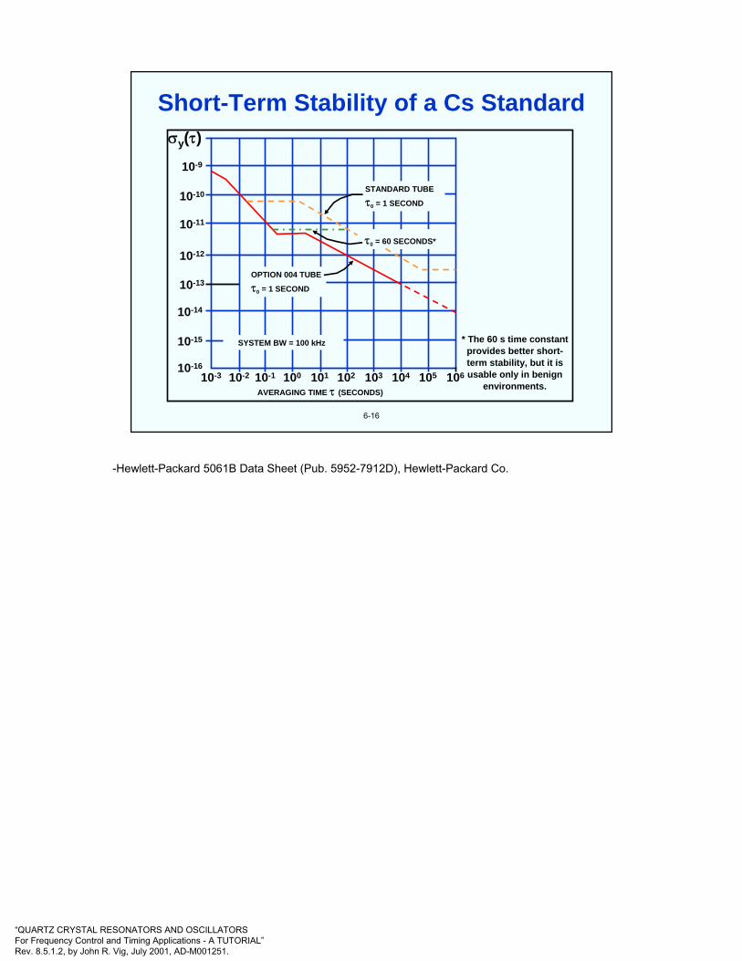
“QUARTZ CRYSTAL RESONATORS AND OSCILLATORSFor Frequency Control and Timing Applications - A TUTORIAL”Rev. 8.5.1.2, by John R. Vig, July 2001, AD-M001251.
6-16
STANDARD TUBE
τ0 = 1 SECOND
τ0 = 60 SECONDS*
OPTION 004 TUBE
τ0 = 1 SECOND
SYSTEM BW = 100 kHz
σy(τ)10-9
10-10
10-11
10-12
10-13
10-14
10-15
10-1610-3 10-2 10-1 100 101 102 103 104 105 106
AVERAGING TIME τ (SECONDS)
* The 60 s time constantprovides better short-term stability, but it isusable only in benign
environments.
Short-Term Stability of a Cs Standard
-Hewlett-Packard 5061B Data Sheet (Pub. 5952-7912D), Hewlett-Packard Co.
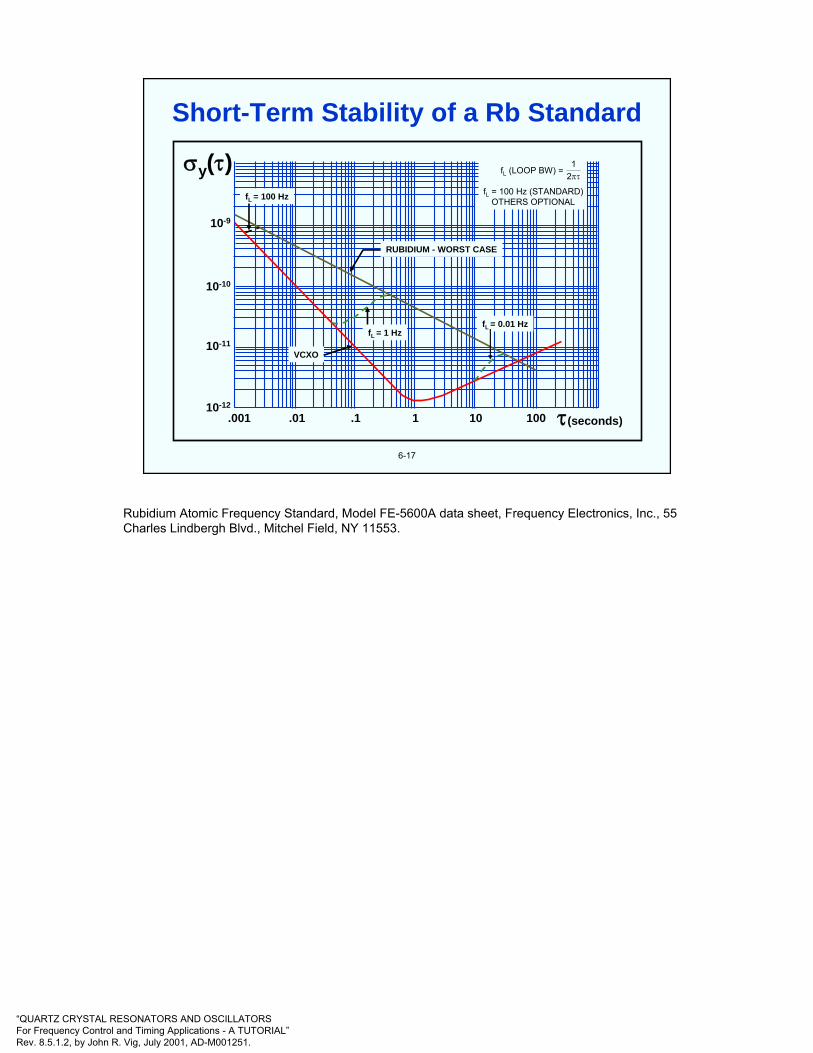
“QUARTZ CRYSTAL RESONATORS AND OSCILLATORSFor Frequency Control and Timing Applications - A TUTORIAL”Rev. 8.5.1.2, by John R. Vig, July 2001, AD-M001251.
6-17
.001 .01 .1 1 10 100 τ(seconds)
10-9
10-10
10-11
10-12
σy(τ) fL (LOOP BW) =
fL = 100 Hz (STANDARD)OTHERS OPTIONAL
πτ21
fL = 0.01 HzfL = 1 Hz
VCXO
RUBIDIUM - WORST CASE
fL = 100 Hz
Short-Term Stability of a Rb Standard
Rubidium Atomic Frequency Standard, Model FE-5600A data sheet, Frequency Electronics, Inc., 55 Charles Lindbergh Blvd., Mitchel Field, NY 11553.

“QUARTZ CRYSTAL RESONATORS AND OSCILLATORSFor Frequency Control and Timing Applications - A TUTORIAL”Rev. 8.5.1.2, by John R. Vig, July 2001, AD-M001251.
6-18
Let the servo loop time constant = t0, let the atomic standard's Γ = ΓA, and the crystal oscillator’s (VCXO's) Γ = ΓO. Then,
• For fast acceleration changes (fvib >> 1/2πt0), ΓA = ΓO
• For slow acceleration changes, (fvib << 1/2πt0), ΓA << ΓO
• For fvib ≈ fmod, 2fmod, servo is confused, ΓA ≈ ΓO, plus a frequency offset
• For small fvib, (at Bessel function null), loss of lock, ΓA ≈ ΓO
AtomicResonatorAtomic
ResonatorFeedbackFeedback
MultiplierMultiplier QuartzCrystal
Oscillator
QuartzCrystal
Oscillator
5 MHz Output
Acceleration Sensitivity of Atomic Standards
J. R. Vig, C. Audoin, L. S. Cutler, M. M. Driscoll, E. P. EerNisse, R. L. Filler, R. M. Garvey, W. L. Riley, R. C. Smythe, and R. D. Weglein, "Acceleration, Vibration and Shock Effects - IEEE Standards Project P1193," Proc. 1992 IEEE Frequency Control Symposium, 763-781, 1992.

“QUARTZ CRYSTAL RESONATORS AND OSCILLATORSFor Frequency Control and Timing Applications - A TUTORIAL”Rev. 8.5.1.2, by John R. Vig, July 2001, AD-M001251.
6-19
In Rb cell standards, high acceleration can cause ∆f due to light shift, power shift, and servo effects:
• Location of molten Rb in the Rb lamp can shift• Mechanical changes can deflect light beam• Mechanical changes can cause rf power changes
In Cs beam standards, high acceleration can cause ∆f due to changes in the atomic trajectory with respect to the tube & microwave cavity structures:
• Vibration modulates the amplitude of the detected signal. Worst when fvib = f mod.
• Beam to cavity position change causes cavity phase shift effects
• Velocity distribution of Cs atoms can change• Rocking effect can cause ∆f even when fvib < f mod
In H-masers, cavity deformation causes ∆f due to cavity pulling effect
Atomic Standard Acceleration Effects
J. R. Vig, C. Audoin, L. S. Cutler, M. M. Driscoll, E. P. EerNisse, R. L. Filler, R. M. Garvey, W. L. Riley, R. C. Smythe, and R. D. Weglein, "Acceleration, Vibration and Shock Effects - IEEE Standards Project P1193," Proc. 1992 IEEE Frequency Control Symposium, 763-781, 1992.

“QUARTZ CRYSTAL RESONATORS AND OSCILLATORSFor Frequency Control and Timing Applications - A TUTORIAL”Rev. 8.5.1.2, by John R. Vig, July 2001, AD-M001251.
6-20
Clock transition frequency ν = νo + CHHo2, where CH is the quadratic
Zeeman effect coefficient (which varies as 1/νo).
* Typical values** 1 gauss = 10-4 Tesla; Tesla is the SI unit of magnetic flux density.
Atom
Rb
Cs
H
Transition Frequency
v=6.8 GHz + (574 Hz/G2) B 2
v=9.2 GHz + (427 Hz/G2) B 2
v=1.4 GHz + (2750 Hz/G2) B 2
C-field*(milligauss)**
250
60
0.5
ShieldingFactor*
5k
50k
50k
Sensitivityper gauss**
10-11
10-13
10-13
o
o
o
Magnetic Field Sensitivities of Atomic Clocks
-
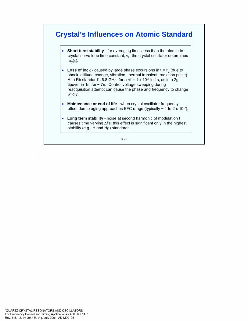
“QUARTZ CRYSTAL RESONATORS AND OSCILLATORSFor Frequency Control and Timing Applications - A TUTORIAL”Rev. 8.5.1.2, by John R. Vig, July 2001, AD-M001251.
6-21
• Short term stability - for averaging times less than the atomic-to-crystal servo loop time constant, τL, the crystal oscillator determinesσy(τ).
• Loss of lock - caused by large phase excursions in t < τL (due toshock, attitude change, vibration, thermal transient, radiation pulse). At a Rb standard's 6.8 GHz, for a ∆f = 1 x 10⁻⁹ in 1s, as in a 2g tipover in 1s, ∆φ ~ 7π. Control voltage sweeping during reacquisition attempt can cause the phase and frequency to change wildly.
• Maintenance or end of life - when crystal oscillator frequencyoffset due to aging approaches EFC range (typically ~ 1 to 2 x 10⁻⁷).
• Long term stability - noise at second harmonic of modulation fcauses time varying ∆f's; this effect is significant only in the higheststability (e.g., H and Hg) standards.
Crystal’s Influences on Atomic Standard
-

“QUARTZ CRYSTAL RESONATORS AND OSCILLATORSFor Frequency Control and Timing Applications - A TUTORIAL”Rev. 8.5.1.2, by John R. Vig, July 2001, AD-M001251.
6-22
The proper atomic energy levels are populated by optical pumping with a laser diode. This method provides superior utilization of Cs atoms, and provides the potential advantages of: higher S/N, longer life, lower weight, and the possibility of trading off size for accuracy. A miniature Cs standard of 1 x 10-11 accuracy, and <<1 liter volume, i.e., about 100x higher accuracy than a Rb standard, in a smaller volume (but not necessarily the same shape factor) seems possible.
Fluorescence Detector
•
Detectionlaser
Pumplaser(s)
Oven
Essential Elements of an Optically PumpedCesium Beam Standard
62 P 3/2
62 S 1/2
F = 5
F = 4F = 3
F = 4
F = 3State selection State detection
Tuned laserdiode pumps
Spontaneousdecays
453 MHz
852 nm(~350 THz)
9.192631770 GHz
Atomic Energy Levels
Optically Pumped Cs Standard
The optical pumping technique manipulates the populations in the hyperfine levels of the ground state by exciting transitions to higher principal quantum states with infrared, or higher frequency, light. As shown above, the atoms in one hyperfine level are excited optically to a higher state from which they decay spontaneously to both ground state hyperfine levels. The population of the hyperfine state involved in the stimulated transition is rapidly depleted; the population of the second hyperfine level is enhanced. Microwaves applied at the 9.192…GHz frequency can be locked to the atomic transition frequency, as in a Cs beam standard.
Optical pumping has both advantages and disadvantages compared to magnetic state selection. On the positive side, it can be accomplished in a more compact device and it can enhance the number of atoms in the desired state rather than just rejecting the atoms in the undesired state. On the negative side are increases in complexity, the difficulty of obtaining laser diodes at the proper frequency and with suitable stability (as of 1999), and some additional performance-degrading mechanisms.
Optical pumping can eliminate the need for state-selection magnets, and result in a larger number of atoms contributing to the signal which results in a superior signal-to-noise ratio. In addition, the spatial symmetry of the optical pumping reduces certain frequency shifts.
L. L. Lewis, “Miniature Optically Pumped Cesium Standards,” Proc. 45th Ann. Symp. on Frequency Control, pp. 521-533, 1991.
P. J. Chantry, B. R. McAvoy, J. M. Zomp, and I. Liberman, “Towards A Miniature Laser-pumped Cesium Cell Frequency Standard,” Proc. 1992 IEEE Int’l Frequency Control Symp., pp. 114-122, 1992.
P. J. Chantry, I. Liberman, et. al, “Miniature Laser Pumped Cesium Cell Atomic Clock Oscillator,”Proc. 1996 IEEE Int’l Frequency Control Symp., pp. 1002-1010, 1996.

“QUARTZ CRYSTAL RESONATORS AND OSCILLATORSFor Frequency Control and Timing Applications - A TUTORIAL”Rev. 8.5.1.2, by John R. Vig, July 2001, AD-M001251.
Atom
Direction of motion
LightLight
1
2 3 4Directionof force
6-23
Laser Cooling of Atoms
Laser cooling of atoms can create atoms that move very slowly (equivalent to temperatures of microkelvins). This allows long observation times. The slow speed virtually eliminates Doppler shifts, and the long observation times allow high accuracy determinations of atomic transition frequencies, per the Heisenberg uncertainty principle, i.e., ∆E∆t ~ h and E = hν, so ∆ ν ~ 1/∆t. Laser cooling promises frequency accuracies of parts in 1016. The explanation of laser cooling is as follows. The numbers correspond to the numbers in the illustration above:1. Consider two rays of light that bombard an atom. One ray travels in the same direction as the atom,; the other moves in the opposite direction. The frequency of the light is slightly lower than the frequency that the atom readily absorbs.2. From the atom’s perspective, the ray moving in the same direction as the atom is shifted down in frequency; the other ray is shifted up in frequency.3. The atom is likely to absorb the high-frequency light but not the low. It is therefore pushed in a direction opposite its motion and slows down.4. The emission of the absorbed light pushes the atom in some random direction, but if the process is repeated many times, the emission exerts no net force.
Chu, Steven, ”Laser Trapping of Neutral Particles," Scientific American, February 1992, pp. 71-76.
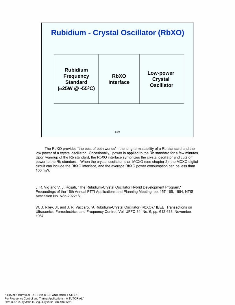
“QUARTZ CRYSTAL RESONATORS AND OSCILLATORSFor Frequency Control and Timing Applications - A TUTORIAL”Rev. 8.5.1.2, by John R. Vig, July 2001, AD-M001251.
6-24
RubidiumFrequencyStandard
(≈25W @ -550C)
RbXOInterface
Low-powerCrystal
Oscillator
Rubidium - Crystal Oscillator (RbXO)
The RbXO provides “the best of both worlds” - the long term stability of a Rb standard and the low power of a crystal oscillator. Occasionally, power is applied to the Rb standard for a few minutes. Upon warmup of the Rb standard, the RbXO interface syntonizes the crystal oscillator and cuts off power to the Rb standard. When the crystal oscillator is an MCXO (see chapter 2), the MCXO digital circuit can include the RbXO interface, and the average RbXO power consumption can be less than 100 mW.
J. R. Vig and V. J. Rosati, "The Rubidium-Crystal Oscillator Hybrid Development Program," Proceedings of the 16th Annual PTTI Applications and Planning Meeting, pp. 157-165, 1984, NTIS Accession No. N85-29221/7.
W. J. Riley, Jr. and J. R. Vaccaro, "A Rubidium-Crystal Oscillator (RbXO)," IEEE Transactions on Ultrasonics, Ferroelectrics, and Frequency Control, Vol. UFFC-34, No. 6, pp. 612-618, November 1987.

“QUARTZ CRYSTAL RESONATORS AND OSCILLATORSFor Frequency Control and Timing Applications - A TUTORIAL”Rev. 8.5.1.2, by John R. Vig, July 2001, AD-M001251.
6-25
Rb ReferencePower Source
RFSample
ControlSignals
RbReference
OCXO
TuningMemory
Output
OCXO and TuningMemory Power Source
ControlVoltage
RbXO Principle of Operation
The Rb reference is a miniature Rb frequency standard (RFS) that has been modified to control an external crystal oscillator. The OCXO includes a digital tuning memory to hold the frequency control voltage while the Rb reference is off. The OCXO is ON continually. At specified intervals, the system applies power to the RFS. After the warmup of the RFS (a few minutes), the interface circuits adjust the frequency of the OCXO to the RFS reference, then shut off the RFS. For portable applications, the OCXO can be separable from the rest of the RbXO (see the next page) so that one can operate with minimum size, weight, and power, and with nearly the accuracy of the RFS for the duration of a mission. An MCXO can be used for even lower power consumption.
W. J. Riley, Jr. and J. R. Vaccaro, "A Rubidium-Crystal Oscillator (RbXO)," IEEE Transactions on Ultrasonics, Ferroelectrics, and Frequency Control, Vol. UFFC-34, No. 6, pp. 612-618, November 1987.

“QUARTZ CRYSTAL RESONATORS AND OSCILLATORSFor Frequency Control and Timing Applications - A TUTORIAL”Rev. 8.5.1.2, by John R. Vig, July 2001, AD-M001251.
Rubidium Crystal Oscillator
Shown above is one implementation of the RbXO - in which the OCXO is detachable.
W. J. Riley, Jr. and J. R. Vaccaro, "A Rubidium-Crystal Oscillator (RbXO)," IEEE Transactions on Ultrasonics, Ferroelectrics, and Frequency Control, Vol. UFFC-34, No. 6, pp. 612-618, November 1987.

“QUARTZ CRYSTAL RESONATORS AND OSCILLATORSFor Frequency Control and Timing Applications - A TUTORIAL”Rev. 8.5.1.2, by John R. Vig, July 2001, AD-M001251.
7
CHAPTER 7Oscillator Comparisons and
Specifications
A listing of "Specifications and Standards Relevant to Frequency Control," appears in the back pages of the Proceedings of the IEEE Frequency Control Symposium - see the proceedings ordering information in chapter 10.
E. Hafner, "Specifications and Standards," in E. A. Gerber and A. Ballato, Precision Frequency Control, Vol. 2, pp. 297-304, Academic Press, 1985.
S. R. Stein and J. R. Vig, "Frequency Standards for Communications," U. S. Army Laboratory Command Research and Development Technical Report SLCET-TR-91-2 (Rev. 1), October 1991, AD-A243211. This report is a reprint of a chapter "Communications Frequency Standards," in The Froehlich/Kent Encyclopedia of Telecommunications, Vol. 3, pp. 445-500, Marcel Dekker, Inc., 1992.

“QUARTZ CRYSTAL RESONATORS AND OSCILLATORSFor Frequency Control and Timing Applications - A TUTORIAL”Rev. 8.5.1.2, by John R. Vig, July 2001, AD-M001251.
7-1
* Including environmental effects (note that the temperature ranges for Rband Cs are narrower than for quartz).
Quartz Oscillators Atomic Oscillators
Accuracy *(per year)
Aging/Year
Temp. Stab.(range, 0C)
Stability,σy(τ)(τ = 1s)
Size(cm3)
Warmup Time(min)
Power (W)(at lowest temp.)
Price (~$)
TCXO2 x 10-6
5 x 10⁻⁷
5 x 10⁻⁷
(-55 to +85)
1 x 10⁻⁹
10
0.03(to 1 x 10⁻⁶)
0.04
10 - 100
MCXO5 x 10-8
2 x 10⁻⁸
3 x 10⁻⁸
(-55 to +85)
3 x 10⁻¹⁰
30
0.03(to 2 x 10⁻⁸)
0.04
<1,000
OCXO1 x 10-8
5 x 10⁻⁹
1 x 10⁻⁹
(-55 to +85)
1 x 10-12
20-200
4(to 1 x 10⁻⁸)
0.6
200-2,000
Rubidium5 x 10-10
2 x 10⁻¹⁰
3 x 10⁻¹⁰
(-55 to +68)
3 x 10-12
200-800
3(to 5 x 10⁻¹⁰)
20
2,000-8,000
RbXO7 x 10-10
2 x 10⁻¹⁰
5 x 10⁻¹⁰
(-55 to +85)
5 x 10-12
1,000
3(to 5 x 10⁻¹⁰)
0.65
<10,000
Cesium2 x 10-11
0
2 x 10-11
(-28 to +65)
5 x 10-11
6,000
20(to 2 x 10-11)
30
50,000
Oscillator Comparison
The specifications in this table are typical for oscillators made for a wide temperature range. Laboratory standards that are designed to operate in a benign environment can perform better. This is especially true for laboratory cesium standards, the accuracy of which can be >100x better than what is shown above.

“QUARTZ CRYSTAL RESONATORS AND OSCILLATORSFor Frequency Control and Timing Applications - A TUTORIAL”Rev. 8.5.1.2, by John R. Vig, July 2001, AD-M001251.
(Goal of R&D is to move technologies toward the upper left)
* Accuracy vs, size, and accuracy vs. cost have similar relationships
10-12
10-10
10-8
10-6
10-4
Acc
urac
y
Power (W)0.01 0.1 1 10 1000.001
XO
TCXOTCXOOCXOOCXO
RbRb
CsCs 1µs/day1ms/year
1ms/day1s/year
1s/day
Clock Accuracy vs. Power Requirement*
7-2
Commercially available frequency sources cover an accuracy range of several orders of magnitude - from the simple XO to the cesium-beam frequency standard. As the accuracy increases, so does the power requirement, size, and cost. Shown above is the relationship between accuracy and power requirement. (Note that it is a log-log scale.) Accuracy versus cost would be a similar relationship, ranging from about $1 for a simple XO to about $40,000 for a cesium standard (1997 prices).

“QUARTZ CRYSTAL RESONATORS AND OSCILLATORSFor Frequency Control and Timing Applications - A TUTORIAL”Rev. 8.5.1.2, by John R. Vig, July 2001, AD-M001251.
(Goal of R&D is to move technologies toward the upper left)
7-3
* Accuracy vs, size, and accuracy vs. cost have similar relationships
10-12
10-10
10-8
10-6
10-4
Acc
urac
y
Power (W)
= in production
= developmental
0.01 0.1 1 10 1000.001XOXO
TCXOTCXO
OCXOOCXO
RbRb
CsCs
MCXO TMXO
RbXO
Mini-Rb/Cs1µs/day1ms/year
1ms/day1s/year
1s/day
Clock Accuracy vs. Power Requirement*
Shown above is the relationship between accuracy and power requirement for the major classes of frequency standards, and for some developmental standards. The accuracies shown are for wide temperature range devices, and include environmental effects and one year of aging. Laboratory standards, (e.g., the best available cesium standard) have higher accuracies.
Power availability often limits the available options. For example, small, handheld devices are limited to XO, TCXO or MCXO.
The MCXO and RbXO were discussed earlier. One version of a miniature Cs standard is discussed at “Optically Pumped Cs Standard,” in chapter 6. Other versions of miniature Rb and Cs standards, e.g., using coherent population trapping (CPT), promise to allow small, low power atomic standards in the future. The TMXO was the Tactical Miniature Crystal Oscillator, was an experimental <20 cm3, low-power (300 mW @-40oC, vacuum insulated) OCXO. Similar size OCXOs are now available commercially.
J. Messina, D. Bowman, R. Filler, R. Lindenmuth, V. Rosati, S. Schodowski, “Results Of Long Term Testing Of Tactical Miniature Crystal Oscillators,” Proc. 43rd Annual Symposium on Frequency Control, pp. 47-50, 1989.
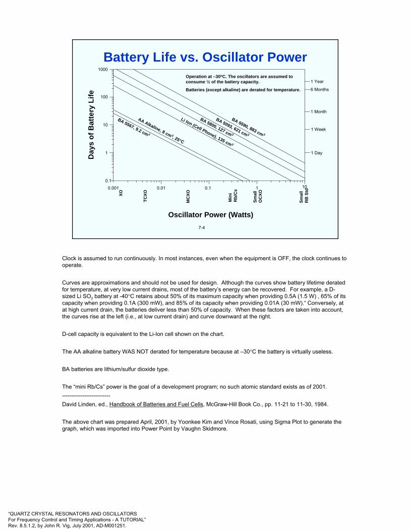
“QUARTZ CRYSTAL RESONATORS AND OSCILLATORSFor Frequency Control and Timing Applications - A TUTORIAL”Rev. 8.5.1.2, by John R. Vig, July 2001, AD-M001251.
Oscillator Power (Watts)
Operation at –30oC. The oscillators are assumed to consume ½ of the battery capacity.
Batteries (except alkaline) are derated for temperature.D
ays
of B
atte
ry L
ife1 Year
6 Months
1 Month
1 Week
1 Day
0.001 0.01 0.1 1 10
XO
TCXO
MC
XO
Min
iR
b/C
s
Smal
lO
CXO
Smal
lR
B S
td
1000
100
10
1
0.1
BA 5567, 9.2 cm 3
AA Alkaline, 8 cm 3, 25°C
Li Ion (Cell Phone), 135 cm 3
BA 5093, 621 cm 3
BA 5800, 127 cm 3
BA 5590, 883 cm 3
7-4
Battery Life vs. Oscillator Power
Clock is assumed to run continuously. In most instances, even when the equipment is OFF, the clock continues to operate.
Curves are approximations and should not be used for design. Although the curves show battery lifetime derated for temperature, at very low current drains, most of the battery’s energy can be recovered. For example, a D-sized Li SO2 battery at -40°C retains about 50% of its maximum capacity when providing 0.5A (1.5 W) , 65% of its capacity when providing 0.1A (300 mW), and 85% of its capacity when providing 0.01A (30 mW).“ Conversely, at at high current drain, the batteries deliver less than 50% of capacity. When these factors are taken into account, the curves rise at the left (i.e., at low current drain) and curve downward at the right.
D-cell capacity is equivalent to the Li-Ion cell shown on the chart.
The AA alkaline battery WAS NOT derated for temperature because at –30°C the battery is virtually useless.
BA batteries are lithium/sulfur dioxide type.
The “mini Rb/Cs” power is the goal of a development program; no such atomic standard exists as of 2001.--------------------------David Linden, ed., Handbook of Batteries and Fuel Cells, McGraw-Hill Book Co., pp. 11-21 to 11-30, 1984.
The above chart was prepared April, 2001, by Yoonkee Kim and Vince Rosati, using Sigma Plot to generate the graph, which was imported into Power Point by Vaughn Skidmore.

“QUARTZ CRYSTAL RESONATORS AND OSCILLATORSFor Frequency Control and Timing Applications - A TUTORIAL”Rev. 8.5.1.2, by John R. Vig, July 2001, AD-M001251.
7-5
Log
(σy(
τ))
Log (τ), seconds-3.0 -2.0 -1.0 0.0 1.0 2.0 3.0 4.0 5.0 6.0 7.0
1 day1 month
-9
-10
-11
-12
-13
-14
-15
-16Hydrogen Maser
Rubidium
Quartz
Cesium
Short Term Stability Ranges of Various Frequency Standards
The above graph is based on one prepared and provided by Richard Sydnor, Jet Propulsion Laboratory, 1989.

“QUARTZ CRYSTAL RESONATORS AND OSCILLATORSFor Frequency Control and Timing Applications - A TUTORIAL”Rev. 8.5.1.2, by John R. Vig, July 2001, AD-M001251.
7-6
Typical one-sided spectral density of phase deviation vs. offset frequency, for various standards, calculated at 5 MHz. L(f) = ½ Sφ
-30
-40-50-60-70
-80-90-100
-110-120-130
-140-150-160
-3 -2 -1 0 1 2 3 4
10*L
og(S
φ(f))
Log (f)
Cesium
Quartz
Hydrogen MaserRubidium
Phase Instabilities of Various Frequency Standards
The above graph is based on one prepared and provided by Richard Sydnor, Jet Propulsion Laboratory, 1989.

“QUARTZ CRYSTAL RESONATORS AND OSCILLATORSFor Frequency Control and Timing Applications - A TUTORIAL”Rev. 8.5.1.2, by John R. Vig, July 2001, AD-M001251.
7-7
Quartz
Rubidium
Cesium
WeaknessesAgingRad hardness
LifePowerWeight
LifePowerWeightCostTemp. range
Wearout MechanismsNone
Rubidium depletionBuffer gas depletionGlass contaminants
Cesium supply depletionSpent cesium getteringIon pump capacityElectron multiplier
Weaknesses and Wearout Mechanisms
See also “Why Do Crystal Oscillators Fail?” on the next page.The wearout mechanisms listed for Rb standards have become less of a problem in recent years
than they were when early GPS satellites failed due to the failure of on-board atomic clocks.
D. Ringer, H. Bethke, and M. Van Melle, “Rubidium and Cesium Frequency Standards - Status and Performance on the GPS Program,” Proc. 16th Precise Time and Time Interval (PTTI) Applications and Planning Meeting, pp. 127-141, 1986, NTIS Accession no. N85-29221/7.
M. J. Van Melle, “Cesium and Rubidium Frequency Standards Status andPerformance on the GPS Program,” Proc. 27th Precise Time and Time Interval (PTTI) Applications and Planning Meeting, pp. 167-180, 1995, NASA Conference Publication 3334.
Lt. R. E. Bower, G. L. Dieter, and M. J. Van Melle,“SVN 20 End-Of-Life Frequency Standard Test Results,” Proc. 29th Precise Time and Time Interval (PTTI) Applications and Planning Meeting, pp. 181- , 1997.
PTTI Proc. Availability information: <http://tycho.usno.navy.mil/ptti/orderform.html>
“QUARTZ CRYSTAL RESONATORS AND OSCILLATORSFor Frequency Control and Timing Applications - A TUTORIAL”Rev. 8.5.1.2, by John R. Vig, July 2001, AD-M001251.
7-8
Crystal oscillators have no inherent failure mechanisms. Some have operated for decades without failure. Oscillators do fail (go out of spec.) occasionally for reasons such as:
• Poor workmanship & quality control - e.g., wires come loose at poor quality solder joints, leaks into the enclosure, and random failure of components
• Frequency ages to outside the calibration range due to high aging plus insufficient tuning range
• TCXO frequency vs. temperature characteristic degrades due to aging and the “trim effect”.
• OCXO frequency vs. temperature characteristic degrades due to shift of oven set point.
• Oscillation stops, or frequency shifts out of range or becomes noisy at certain temperatures, due to activity dips
• Oscillation stops or frequency shifts out of range when exposed to ionizing radiation - due to use of unswept quartz or poor choice of circuit components
• Oscillator noise exceeds specifications due to vibration induced noise
• Crystal breaks under shock due to insufficient surface finish
Why Do Crystal Oscillators Fail?
Aging, trim effect, oven instability effects, activity dips, vibration-induced noise effects, shock effects, and other instabilities are discussed in chapter 4.

“QUARTZ CRYSTAL RESONATORS AND OSCILLATORSFor Frequency Control and Timing Applications - A TUTORIAL”Rev. 8.5.1.2, by John R. Vig, July 2001, AD-M001251.
7-9
• Frequency accuracy or reproducibility requirement
• Recalibration interval
• Environmental extremes
• Power availability - must it operate from batteries?
• Allowable warmup time
• Short term stability (phase noise) requirements
• Size and weight constraints
• Cost to be minimized - acquisition or life cycle cost
Oscillator Selection Considerations
In relation to the last item, i.e., what cost is to be minimized, the initial acquisition cost or the life-cycle cost, often, the cost of recalibration is far higher than the added cost of an oscillator that can provide calibration-free life. A better oscillator may also allow simplification of the system's design.
The frequency of the oscillator can be another important consideration, because the choice can have an impact on both cost and performance. Everything else being equal, an oscillator of standard frequency, such as 5 MHz or 10 MHz, will cost less than one of an unusual frequency, such as 8.34289 MHz. Moreover, for thickness-shear crystals, such as the AT-cut and SC-cut, the lower the frequency, the lower the aging. Since at frequencies much below 5 MHz thickness-shear crystals become too large for economical manufacturing, and since all the highest stability oscillators use thickness-shear crystals, the highest stability commercially available oscillator's frequency is 5 MHz. Such oscillators will also have the lowest phase-noise capability close to the carrier. There are also some excellent 10 MHz oscillators on the market; however, oscillators of much higher frequency than 10 MHz usually have higher aging rates and phase-noise levels close to the carrier than do 5 MHz oscillators. For lowest phase-noise far from the carrier, where the signal-to-noise ratio in the sustaining circuit determines the noise level, higher frequency crystals (e.g., 100 MHz) can provide lower noise because such crystals can tolerate higher drive levels, thereby allowing higher signal levels.
When resonator size is an issue, higher frequency resonators are generally smaller than lower frequency resonators (of the same type). For example, a 100 MHz 5th overtone resonator is substantially smaller than a 5 MHz 5th overtone unit. On the other hand, a 32 kHz watch crystal is much smaller than either.
“QUARTZ CRYSTAL RESONATORS AND OSCILLATORSFor Frequency Control and Timing Applications - A TUTORIAL”Rev. 8.5.1.2, by John R. Vig, July 2001, AD-M001251.
7-10
MIL-PRF-55310D15 March 1998-----------------------SUPERSEDINGMIL-0-55310C15 Mar 1994
PERFORMANCE SPECIFICATION
OSCILLATOR, CRYSTAL CONTROLLED
GENERAL SPECIFICATION FOR
This specification is approved for use by all Departments and Agencies of the Department of Defense.
1. SCOPE
1.1 Statement of scope. This specification covers the general requirements for quartz crystal oscillators used in electronic equipment.
----------------------------------Full text version is available via a link from <http:\\www.ieee.org/uffc/fc>
Crystal Oscillator Specification: MIL-PRF-55310
This document is a good guide for preparing oscillator specifications, whether it be an oscillator for a military or a civilian application, and whether it be a quartz or atomic oscillator.
The complete MIL-PRF-55310 is available on the Internet via a link from <http:\\www.ieee.org/uffc/fc>, or directly, from <http://www.dscc.dla.mil/Programs/MilSpec/ListDocs.asp?BasicDoc=MIL-PRF-55310>
Copies of MIL-PRF-55310 are also available by mail from: Military Specifications and Standards, Bldg. 4D, 700 Robbins Avenue, Philadelphia, PA 19111-5094, USA. Customer Service telephone: (215) 697-2667/2179; Telephone Order Entry System (requires a touch tone telephone and a customer number): (215) 697-1187 thru 1195.

“QUARTZ CRYSTAL RESONATORS AND OSCILLATORSFor Frequency Control and Timing Applications - A TUTORIAL”Rev. 8.5.1.2, by John R. Vig, July 2001, AD-M001251.
8
CHAPTER 8Time and Timekeeping
Proceedings of the IEEE, Special Issue on Time and Frequency, J. Jespersen & D. W. Hanson, ed's., Vol. 79, No. 7, July 1991.
P. Kartaschoff, Frequency and Time, Academic Press, 1978.
G. M. R. Winkler, "Timekeeping and Its Applications," Advances in Electronics and Electron Physics, Vol. 44, pp. 34-97, 1977.
G. Kamas, & M. A. Lombardi, Time & Frequency Users' Manual, NIST Special Publication 559, revised 1990; Time and Frequency Division, NIST, 325 Broadway, Boulder, Colorado, 80303.
Characterization of Clocks and Oscillators, ed. by D. B. Sullivan, et al., NIST Technical Note 1337, 1990, Time and Frequency Division, NIST, 325 Broadway, Boulder, Colorado, 80303.
D. W. Allan, "Frequency and Time Coordination, Comparison, and Dissemination," in E. A. Gerber and A. Ballato, Precision Frequency Control, Vol. 2, pp. 233-273, Academic Press, 1985.
H. Hellwig, K. M. Evenson and D. J. Wineland, "Time, Frequency and Physical Measurement," Physics Today, pp. 23-30, December 1978.
“The Science of Timekeeping,” Application Note 1289, Hewlett Packard Co., 1997.
"Fundamentals of Time and Frequency Standards," Application Note 52-1, Hewlett Packard Co., September 1986.
"Timekeeping and Frequency Calibration,” Application Note 52-2, Hewlett Packard Co., November 1986.HP application notes can be found at: <http://www.tmo.hp.com/tmo/Notes/English/>R. Morris, Time's Arrows - Scientific Attitudes Toward Time, Simon and Schuster, NY, 1985.

“QUARTZ CRYSTAL RESONATORS AND OSCILLATORSFor Frequency Control and Timing Applications - A TUTORIAL”Rev. 8.5.1.2, by John R. Vig, July 2001, AD-M001251.
8-1
• "What, then, is time? If no one asks me, I know; if I wish to explain to him who asks, I know not." --- Saint Augustine, circa 400 A.D.
• The question, both a philosophical and a scientific one, has no entirely satisfactory answer. "Time is what a clock measures." "It defines the temporal order of events." "It is an element in the four-dimensional geometry of space-time.” “It is nature’s way of making sure that everything doesn't happen at once.”
• Why are there "arrows" of time? The arrows are: entropy, electromagnetic waves, expansion of the universe, k-meson decay, and psychological. Does time have a beginning and an end? (Big bang; no more "events", eventually.)
• The unit of time, the second, is one of the seven base units in the International System of Units (SI units)*. Since time is the quantity that can be measured with the highest accuracy, it plays a central role in metrology.
What Is Time?
None of the fundamental laws of physics distinguish between the forward and backward directions of time; e.g., the laws of mechanics are valid when time is reversed. If the collision of two particles is recorded, and the recording is played forward and backward, there is no way to tell the “correct” direction. The particles follow the laws of physics in either direction. However, five ways have been found in which the directions of time, the “arrows of time,” can be distinguished. The most important arrow is the second law of thermodynamics, according to which the past and future look different; there will be more entropy tomorrow, there was less entropy yesterday. (The second law is not a fundamental law; it is a statistical law; it cannot be applied to a single particle or a small number of particles.)
In the laws of physics, there is no “present moment.” The laws deal only with time intervals. The “flow of time” cannot be measured. “At best, one can say only that time moves onward at the rate of one second per second, which is about as meaningful as defining the word ‘cat’ by saying, ‘A cat is a cat.’ “. **
* See “Units of Measurement Having Special Names in the International System of Units (SI)” and the following page later in this chapter.
** R. Morris, Time's Arrows - Scientific Attitudes Toward Time, Simon and Schuster, NY, 1985.
K. Lippincott, et. al, The Story of Time, Merrell Holberton Publishers in association with National Maritime Museum (UK), 1999.

“QUARTZ CRYSTAL RESONATORS AND OSCILLATORSFor Frequency Control and Timing Applications - A TUTORIAL”Rev. 8.5.1.2, by John R. Vig, July 2001, AD-M001251.
tim e (tim ), n ., adj., u , tim ed, tim ~ ing. — n. 1 . the systemof those sequential re la tions that any event has to anyother, as past, p resent, or future , indefin ite and con-tinuous duration regarded as that in w hich events suc-ceed one another. 2. dura tion regarded as be long ing tothe present life as d is tinct from the life to com e or frometern ity ; fin ite duration. 3 . (som etim es cap.) a systemor m ethod o f m easuring or reckon ing the passage o ftim e: m ean tim e; apparent tim e; G reenw ich T im e. 4 . alim ited period or in terva l, as betw een tw o successiveevents: a long tim e. 5. a particu lar period consideredas d is tinct from other periods: Y outh is the best tim e o flife . 6. O ften, tim es. a . a period in the h is tory o f thew orld , or contem porary w ith the life or activ ities o f anotab le person: preh is toric tim es; in L inco ln 's tim e. b.the period or era now or prev iously present: a s ign o fthe tim es ; H ow tim es have changed! c. a periodconsidered w ith re ference to it’s events or preva ilingconditions, tendencies Ideas, e tc .: hard tim es; a tim e ofw ar. 7. a prescribed or a llo tted period, as o f one 's life ,for paym ent o f a debt, e tc . 8 . the end o f a prescribed ora llo tted period, as o f one's life or a pregnancy: H is tim ehad com e, but there w as no one le ft to m ourn overh im . W hen her tim e cam e, her husband accom paniedher to the de livery room . 9. a period w ith re ference topersonal experience o f a specified k ind: to have a goodtim e; a hot tim e in the old tow n ton ight. 10 . a period o fw ork o f an em ployee, or the pay for it; w ork ing hours ordays or an hourly or da ily pay ra te . 11 . In form al. a termof enforced duty or im prisonm ent: to serve tim e in thearm y, do tim e in prison. 12 . the period necessary for oroccup ied by som eth ing: The tim e o f the basebaII gam ew as tw o hours and tw o m inutes. The bus takes toom uch tim e, so I'll take a p lane. 13 . Ie isure tim e;suffic ient or spare tim e: to have tim e for a vacation; Ihave no tim e to s top now . 14. a particu lar or defin itepo in t in tim e, as ind icated by a c lock : W hat tim e is it?15. a particu lar part o f a year, day, e tc .; season orperiod: It's tim e for lunch . 16 . an appoin ted, fit, due, orproper instant or period: A tim e for sow ing; the tim ew hen the sun crosses the m erid ian There is A tim e foreveryth ing. 17. the particu lar poin t in tim e w hen anevent Is scheduled to take p lace: tra in tim e; curta intim e. 18 . an indefin ite , frequently pro longed period orduration in the fu ture : Tim e w ill te ll if w hat w e havedone here today w as right. 19. the right occasion oropportun ity : to w atch one 's tim e. 20 . each occasion o fa recurring action or event: to do a th ing five tim es , It's
the pitcher's tim e a t bat. 21. tim es, used as am ultip lica tive w ord in phrasa l com binations expressinghow m any ins tances o f a quantity or factor are takentogether: Tw o goes in to s ix three tim es, five tim esfaster 22. D ram a. one o f the three un ities. C f. unity(def. 8 ) 23 . P ros. a un it o r a group o f un its in them easurem ent o f m eter. 24. M us ic a . tem po, re la tiverap id ity o f m ovem ent. b. the m etrica l dura tion of a noteor rest. c. p roper or characteris tic tem po. d . the genera lm ovem ent o f a particu lar k ind o f m usica l com positionw ith re ference to its rhythm , m etrica l s tructure , andtem po. e. the m ovem ent o f a dance or the like to m us icso arranged: w altz tim e. 25 . M il. ra te o f m arch ing,ca lcu la ted on the num ber o f paces taken per m inute :double tim e; quick tim e. 26. M anege. each com ple tedaction or m ovem ent o f the horse. 27. against tim e, inan e ffort to fin ish som eth ing w ith in a lim ited period: W ew orked aga inst tim e to get out the new spaper. 28 .ahead of tim e, before the tim e due; early : The bu ild ingw as com pleted ahead o f tim e. 29 . at one tim e, a .once; in a form er tim e: A t one tim e they ow ned arestaurant. b . at the sam e tim e ; a t once: They a ll triedto ta lk a t one tim e . 30 . at the sam e tim e, neverthe less;yet: I'd like to try it bu t a t the sam e tim e I'm a little
a fra id 31. at tim es at in terva ls ; occasiona lly : At tim esthe c ity becom es in to lerab le . 32. beat som eone'stim e. Slang. to com pete for or w in a person be ingdated or courted by another; preva il over a riva l: H eaccused m e, h is ow n bro ther, o f try ing to beat h is tim e.33. behind the tim es, old-fash ioned; dated: Theseattitudes are behind the tim es. 34. for the tim e being,tem porarily; fo r the present: Let's forget about it fo rthe tim e be ing. 35 . from tim e to tim e, on occasion;occasionally ; a t in terva ls : S he com es to see us fromtim e to tim e. 36. gain tim e, to postpone in order tom ake preparations or ga in an advantage de lay theoutcom e of: H e hoped to ga in tim e by putting offsign ing the papers fo r a few days m ore. 37. in goodtim e, a . at the right tim e; on tim e, punctua lly . b . in ad-vance of the right tim e; early : W e arrived a t the ap-po in ted spot in good tim e. 38. in no tim e, in a verybrie f tim e; a lm ost a t once: W orking together, theycleaned the entire house in no tim e. 39. in tim e, a .early enough: to com e in tim e for d inner. b . in the fu-ture ; eventua lly : In tim e he 'll see w hat is righ t. c . in thecorrect rhythm or tem po: There w ould a lw ays be a tleast one ch ild w ho cou ldn't p lay in tim e w ith the m us ic40 . keep tim e, a . to record tim e, as a w atch or c lock
does h to m ark or observe the tem po. c.to performrhythm ic m ovem ents in un ison. 41 . kill tim e, to occupyonese lf w ith som e activ ity to m ake tim e pass qu ick ly :W hile I w as w aiting , I k illed tim e counting the cars onthe fre ight tra ins . 42 . m ake tim e, a . to m ove quick ly ,esp. in an a ttem pt to recover lost tim e. b. to trave l a t aparticu lar speed. 43. m ake tim e w ith , S lang. to pursueor take as a sexua l partner. 44. m any a tim e, againand aga in ; frequently : M any a tim e they d idn 't haveenough to eat and w ent to bed hungry. 45. m ark tim e,a. to suspend progress tem porarily , as to aw aitdeve lopm ents; fa il to advance. b. M il. to m ove the feeta lternate ly as in m arch ing, but w ithout advanc ing. 46 .on one's ow n tim e, during one 's free tim e; w ithoutpaym ent: H e w orked out m ore effic ient productionm ethods on h is ow n tim e. 47. on tim e, a . at thespecified tim e; punctuaB y. b . to be pa id for w ith in adesignated period o f tim e, as in insta llm ents: M anypeople are never out o f debt because they buyeveryth ing on tim e. 48 . out o f tim e, not in the properrhythm : H is s ing ing w as out o f tim e w ith the m usic 49.P ass the tim e of day. to converse brie fly w ith or greetsom eone: The w om en w ould stop in the m arket topass the tim e o f day. 50. take one's tim e, to be s lowor le isure ly ; daw dle : S peed w as im portant here , but hejus t took h is tim e. 51. tim e after tim e. again and aga in ;repeated ly ; o ften: I've to ld h im tim e a fter tim e not tos lam the door. 52 . tim e and tim e again , repeated ly ;o ften: Tim e and tim e aga in I w arned her to s topsm oking. A lso, tim e and again . 53 . tim e of llfe ,(one 's) age: At your tim e o f life you m ust be care fu l notto overdo th ings. 54. tim e of one's life , In fo rm al. anextrem ely en joyab le experience: They had the tim e o fthe ir lives on the ir trip to Europe.. 55 . o f. perta in ing to ,or show ing the passage o f tim e 56. (o f an exp los ivedevice) conta in ing a c lock so that it w ill de tonate a t thedesired m om ent a tim e bom b 57 . C om . payable a t asta ted period o f tim e a fter presentm ent: tim e drafts ornotes. 58. o f or perta in ing to purchases on theins tallm ent p lan, or w ith paym ent pos tponed. v .t. 59. tom easure or record the speed, dura tion, or ra te o f: totim e a race. 60. to fix the duration o f: The proctor tim edthe test a t 16 m inutes. 61. to fix the in terva l betw een(actions, events, e tc .): They tim ed the ir s trokes a t s ixper m inute . 62 . to regula te (a tra in , c lock e tc.) as totim e. 63 . to appo in t or choose the m om ent or occaslonfor; schedule : H e tim ed the a ttack perfectly . — v.i. 64.to keep tim e; sound or m ove in un ison. [bef. 900; (n .)
(From The Random House Dictionary of the English Language ©1987)
8-2
Dictionary Definition of “Time”
-
“QUARTZ CRYSTAL RESONATORS AND OSCILLATORSFor Frequency Control and Timing Applications - A TUTORIAL”Rev. 8.5.1.2, by John R. Vig, July 2001, AD-M001251.
8-3
• The SI unit of time is the second (symbol s).
• The second was defined, by international agreement, in October,1967, at the XIII General Conference of Weights and Measures.
• The second is "the duration of 9,192,631,770 periods of theradiation corresponding to the transition between the twohyperfine levels of the ground state of the cesium atom 133."
• Prior to 1967, the unit of time was based on astronomicalobservations; the second was defined in terms of ephemeris time, i.e., as "1/31,556,925.9747 of the tropical year..."
• The unit of frequency is defined as the hertz (symbol Hz). One hertz equals the repetitive occurrence of one "event" per second.
The Second
More information about the SI units can be found later in this chapter.
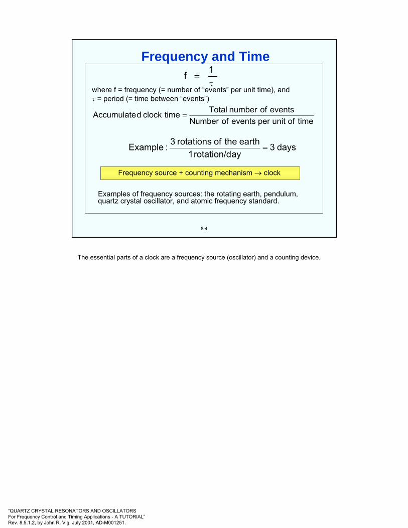
“QUARTZ CRYSTAL RESONATORS AND OSCILLATORSFor Frequency Control and Timing Applications - A TUTORIAL”Rev. 8.5.1.2, by John R. Vig, July 2001, AD-M001251.
8-4
τ=
1fwhere f = frequency (= number of “events” per unit time), andτ = period (= time between “events”)
Frequency source + counting mechanism → clock
Examples of frequency sources: the rotating earth, pendulum,quartz crystal oscillator, and atomic frequency standard.
timeofunitpereventsofNumbereventsofnumberTotaltimeclockdAccumulate =
days3ayrotation/d1
earththeofrotations3:Example =
Frequency and Time
The essential parts of a clock are a frequency source (oscillator) and a counting device.

“QUARTZ CRYSTAL RESONATORS AND OSCILLATORSFor Frequency Control and Timing Applications - A TUTORIAL”Rev. 8.5.1.2, by John R. Vig, July 2001, AD-M001251.
t = t0 + Σ∆τ
Where t is the time output, t0 is the initial setting, and ∆τ is the time interval being counted.
8-5
FrequencySource
CountingMechanism
SettingMechanism
SynchronizationMechanism
Display orTime code
Typical Clock System
A clock may or may not have a display. In many consumer applications, clocks display the time of day. In many other applications, clocks are used internally only; their output is typically a one-pulse-per-second (1 pps) or a time code signal which are used for sequencing or time-tagging events (see “One Pulse-Per-Second Timing Signal” and “BCD Time Code” later in this chapter.

“QUARTZ CRYSTAL RESONATORS AND OSCILLATORSFor Frequency Control and Timing Applications - A TUTORIAL”Rev. 8.5.1.2, by John R. Vig, July 2001, AD-M001251.
8-6
• Sundials, and continuous flow of:• Water (clepsydra)• Sand (hour glass)• Falling weights, with frictional control of rate
• Vibrating, but non-resonant motion - escapement mechanisms: falling weight applies torque through train of wheels; rate control depends on moments of inertia, friction and torque; period is the time it takes to move fromone angular position to another.
• Resonant control• Mechanical: pendulum, hairspring and balance wheel• Mechanical, electrically driven: tuning fork, quartz
resonator• Atomic and molecular
Evolution of Clock Technologies
H. Tait, Clocks and Watches, British Museum Publications, 1983
W. A. Marrison, “The Evolution of the Quartz Crystal Clock,” The Bell System Technical Journal, Vol. XXVII, pp. 510-588, 1948. Reprinted at <http://www.ieee.org/uffc/fc>
<http://www.horology.com/>

“QUARTZ CRYSTAL RESONATORS AND OSCILLATORSFor Frequency Control and Timing Applications - A TUTORIAL”Rev. 8.5.1.2, by John R. Vig, July 2001, AD-M001251.
8-7
Time Period
4th millennium B.C.Up to 1280 A.D.~1280 A.D.
14th century
~134515th century16th century
165618th century19th century~1910 to 19201920 to 19341921 to present1949 to present
Clock/Milestone
Day & night divided into 12 equal hoursSundials, water clocks (clepsydrae)Mechanical clock invented- assembly time for prayerwas first regular useInvention of the escapement; clockmaking becomesa major industryHour divided into minutes and secondsClock time used to regulate people’s lives (work hours)Time’s impact on science becomes significant(Galileo times physical events, e.g., free-fall)First pendulum clock (Huygens)Temperature compensated pendulum clocksElectrically driven free-pendulum clocksWrist watches become widely availableElectrically driven tuning forksQuartz crystal clocks (and watches. Since ~1971)Atomic clocks
Accuracy Per Day
~1 h~30 to 60 min
~15 to 30 min
~2 min~1 min
~100 s1 to 10 s10-2 to 10-1 s
10-3 to 10-2 s10-5 to 10-1 s10-9 to 10-4 s
Progress in Timekeeping
H. Tait, Clocks and Watches, British Museum Publications, 1983
W. A. Marrison, “The Evolution of the Quartz Crystal Clock,” The Bell System Technical Journal, Vol. XXVII, pp. 510-588, 1948. Reprinted at <http://www.ieee.org/uffc/fc>
<http://www.horology.com/>
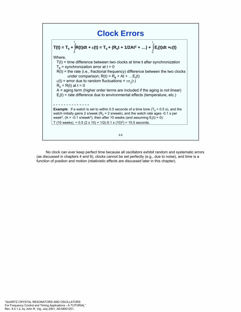
“QUARTZ CRYSTAL RESONATORS AND OSCILLATORSFor Frequency Control and Timing Applications - A TUTORIAL”Rev. 8.5.1.2, by John R. Vig, July 2001, AD-M001251.
8-8
T(t) = T0 + R(t)dt + ε(t) = T0 + (R0t + 1/2At2 + …) + Ei(t)dt +ε(t)
Where,T(t) = time difference between two clocks at time t after synchronizationT0 = synchronization error at t = 0R(t) = the rate (i.e., fractional frequency) difference between the two clocks
under comparison; R(t) = R0 + At + …Ei(t)ε(t) = error due to random fluctuations = τσy(τ)R0 = R(t) at t = 0A = aging term (higher order terms are included if the aging is not linear)Ei(t) = rate difference due to environmental effects (temperature, etc.)
- - - - - - - - - - - - - -Example: If a watch is set to within 0.5 seconds of a time tone (T0 = 0.5 s), and thewatch initially gains 2 s/week (R0 = 2 s/week), and the watch rate ages -0.1 s perweek2, (A = -0.1 s/week2), then after 10 weeks (and assuming Ei(t) = 0):T (10 weeks) = 0.5 (2 x 10) + 1/2(-0.1 x (10)2) = 15.5 seconds.
∫t
0∫t
0
Clock Errors
No clock can ever keep perfect time because all oscillators exhibit random and systematic errors (as discussed in chapters 4 and 6), clocks cannot be set perfectly (e.g., due to noise), and time is a function of position and motion (relativistic effects are discussed later in this chapter).
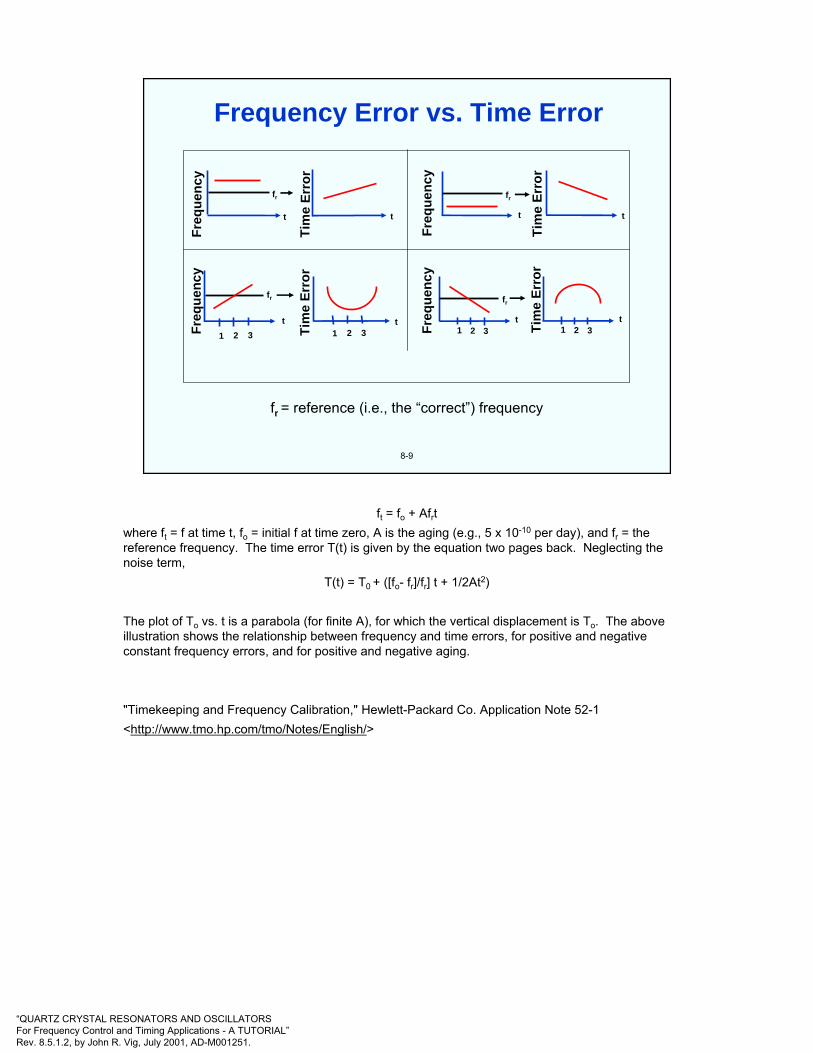
“QUARTZ CRYSTAL RESONATORS AND OSCILLATORSFor Frequency Control and Timing Applications - A TUTORIAL”Rev. 8.5.1.2, by John R. Vig, July 2001, AD-M001251.
8-9
fr = reference (i.e., the “correct”) frequencyFr
eque
ncy
t
Tim
e Er
ror
1 2 3t
1 2 3
fr
t
Freq
uenc
y
Tim
e Er
r or
t
fr
Freq
uenc
y
Tim
e Er
ror
t t
fr
3t
Tim
e Er
ror
1 2t
fr
1 2 3Freq
uenc
y
Frequency Error vs. Time Error
ft = fo + Afrtwhere ft = f at time t, fo = initial f at time zero, A is the aging (e.g., 5 x 10⁻¹⁰ per day), and fr = the reference frequency. The time error T(t) is given by the equation two pages back. Neglecting the noise term,
T(t) = T0 + ([fo- fr]/fr] t + 1/2At2)
The plot of To vs. t is a parabola (for finite A), for which the vertical displacement is To. The above illustration shows the relationship between frequency and time errors, for positive and negative constant frequency errors, and for positive and negative aging.
"Timekeeping and Frequency Calibration," Hewlett-Packard Co. Application Note 52-1<http://www.tmo.hp.com/tmo/Notes/English/>
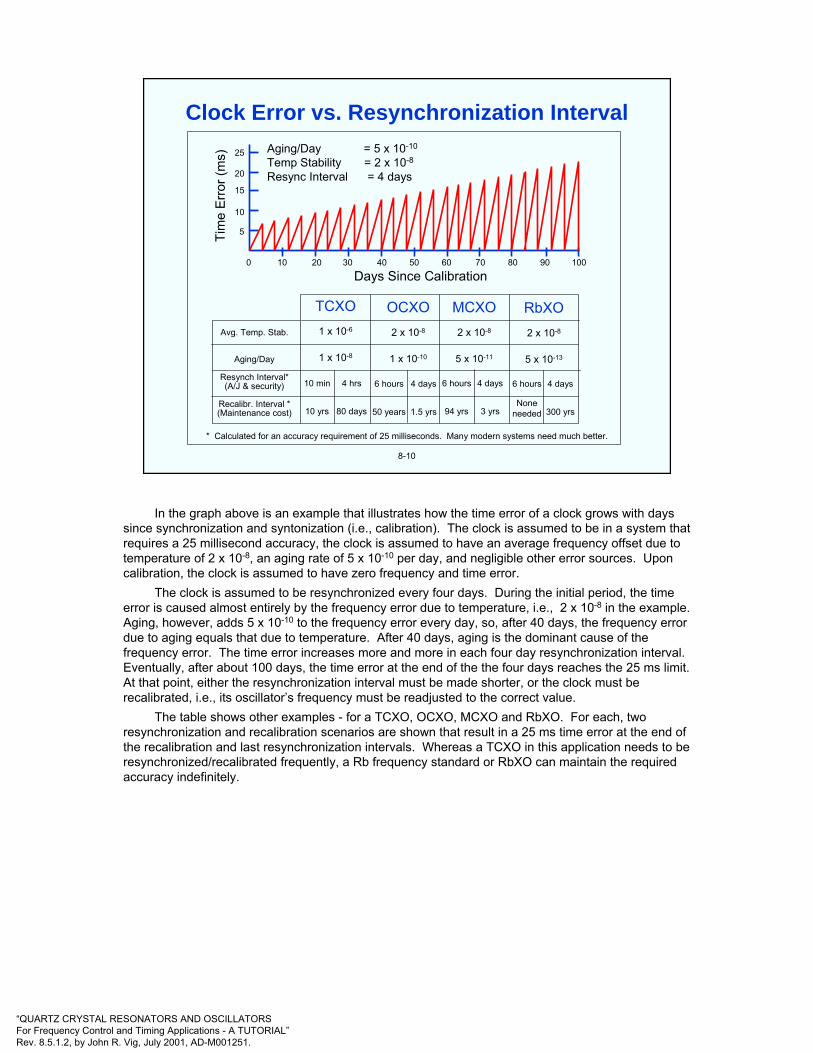
“QUARTZ CRYSTAL RESONATORS AND OSCILLATORSFor Frequency Control and Timing Applications - A TUTORIAL”Rev. 8.5.1.2, by John R. Vig, July 2001, AD-M001251.
8-10
Avg. Temp. Stab.
Aging/Day
Resynch Interval*(A/J & security)
Recalibr. Interval *(Maintenance cost)
TCXO1 x 10-6
1 x 10⁻⁸
10 min
10 yrs
4 hrs
80 days
OCXO2 x 10-8
1 x 10⁻¹⁰
6 hours
50 years
4 days
1.5 yrs
MCXO2 x 10-8
5 x 10-11
4 days
3 yrs
6 hours
94 yrs
RbXO2 x 10-8
5 x 10-13
6 hours
Noneneeded
4 days
300 yrs
* Calculated for an accuracy requirement of 25 milliseconds. Many modern systems need much better.
25
20
15
10
5
0 10 20 30 40 50 60 70 80 90 100
Days Since Calibration
Tim
e E
rror
( ms) Aging/Day = 5 x 10⁻¹⁰
Temp Stability = 2 x 10⁻⁸
Resync Interval = 4 days
Clock Error vs. Resynchronization Interval
In the graph above is an example that illustrates how the time error of a clock grows with days since synchronization and syntonization (i.e., calibration). The clock is assumed to be in a system that requires a 25 millisecond accuracy, the clock is assumed to have an average frequency offset due to temperature of 2 x 10⁻⁸, an aging rate of 5 x 10⁻¹⁰ per day, and negligible other error sources. Upon calibration, the clock is assumed to have zero frequency and time error.
The clock is assumed to be resynchronized every four days. During the initial period, the time error is caused almost entirely by the frequency error due to temperature, i.e., 2 x 10⁻⁸ in the example. Aging, however, adds 5 x 10⁻¹⁰ to the frequency error every day, so, after 40 days, the frequency error due to aging equals that due to temperature. After 40 days, aging is the dominant cause of the frequency error. The time error increases more and more in each four day resynchronization interval. Eventually, after about 100 days, the time error at the end of the the four days reaches the 25 ms limit. At that point, either the resynchronization interval must be made shorter, or the clock must be recalibrated, i.e., its oscillator’s frequency must be readjusted to the correct value.
The table shows other examples - for a TCXO, OCXO, MCXO and RbXO. For each, two resynchronization and recalibration scenarios are shown that result in a 25 ms time error at the end of the recalibration and last resynchronization intervals. Whereas a TCXO in this application needs to be resynchronized/recalibrated frequently, a Rb frequency standard or RbXO can maintain the required accuracy indefinitely.
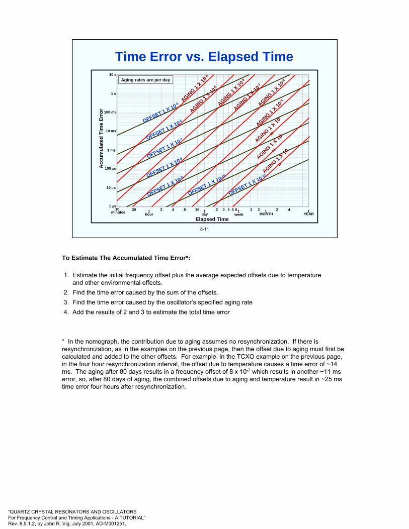
“QUARTZ CRYSTAL RESONATORS AND OSCILLATORSFor Frequency Control and Timing Applications - A TUTORIAL”Rev. 8.5.1.2, by John R. Vig, July 2001, AD-M001251.
8-11
10 s
1 s
100 ms
10 ms
1 ms
100 µs
10 µs
1 µs10 30 1 2 4 8 16 1 2 3 4 5 61 2 3 1 2 4 1minutes hour day week MONTH YEAR
Elapsed Time
Acc
umul
ated
Tim
e Er
ror
Aging rates are per day
OFFSET 1 X 10⁻⁵
OFFSET 1 X 10⁻⁶
OFFSET 1 X 10⁻⁷
OFFSET 1 X 10⁻⁸
OFFSET 1 X 10⁻⁹
OFFSET 1 X 10⁻¹⁰
OFFSET 1 X 10-11
AGING 1
X 10-5
AGING 1
X 10-6
AGING 1
X 10-7
AGING 1
X 10-8
AGING 1
X 10-9
AGING 1
X 10-
10
AGING 1
X 10-
11
AGING 1 X 10
-
12
AGING 1
X 10-4
Time Error vs. Elapsed Time
To Estimate The Accumulated Time Error*:
1. Estimate the initial frequency offset plus the average expected offsets due to temperature and other environmental effects.
2. Find the time error caused by the sum of the offsets.3. Find the time error caused by the oscillator’s specified aging rate4. Add the results of 2 and 3 to estimate the total time error
* In the nomograph, the contribution due to aging assumes no resynchronization. If there is resynchronization, as in the examples on the previous page, then the offset due to aging must first be calculated and added to the other offsets. For example, in the TCXO example on the previous page, in the four hour resynchronization interval, the offset due to temperature causes a time error of ~14 ms. The aging after 80 days results in a frequency offset of 8 x 10⁻⁷ which results in another ~11 ms error, so, after 80 days of aging, the combined offsets due to aging and temperature result in ~25 ms time error four hours after resynchronization.
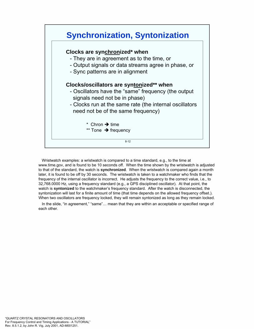
“QUARTZ CRYSTAL RESONATORS AND OSCILLATORSFor Frequency Control and Timing Applications - A TUTORIAL”Rev. 8.5.1.2, by John R. Vig, July 2001, AD-M001251.
8-12
Clocks are synchronized* when- They are in agreement as to the time, or- Output signals or data streams agree in phase, or- Sync patterns are in alignment
Clocks/oscillators are syntonized** when- Oscillators have the “same” frequency (the output signals need not be in phase)
- Clocks run at the same rate (the internal oscillators need not be of the same frequency)
* Chron time** Tone frequency
Synchronization, Syntonization
Wristwatch examples: a wristwatch is compared to a time standard, e.g., to the time at www.time.gov, and is found to be 10 seconds off. When the time shown by the wristwatch is adjusted to that of the standard, the watch is synchronized. When the wristwatch is compared again a month later, it is found to be off by 30 seconds. The wristwatch is taken to a watchmaker who finds that the frequency of the internal oscillator is incorrect. He adjusts the frequency to the correct value, i.e., to 32,768.0000 Hz, using a frequency standard (e.g., a GPS disciplined oscillator). At that point, the watch is syntonized to the watchmaker’s frequency standard. After the watch is disconnected, the syntonization will last for a finite amount of time (that time depends on the allowed frequency offset.). When two oscillators are frequency locked, they will remain syntonized as long as they remain locked.
In the slide, “in agreement,” “same”… mean that they are within an acceptable or specified range of each other.

“QUARTZ CRYSTAL RESONATORS AND OSCILLATORSFor Frequency Control and Timing Applications - A TUTORIAL”Rev. 8.5.1.2, by John R. Vig, July 2001, AD-M001251.
8-13
It takes time to measure the clock rate (i.e., frequency) difference between two clocks. The smaller the rate difference between a clock to be calibrated and a reference clock, the longer it takes to measure the difference (∆t/t ≈ ∆f/f).
For example, assume that a reference timing source (e.g., Loran or GPS) with a random time uncertainty of 100 ns is used to calibrate the rate of a clock to 1 x 10-11 accuracy. A frequency offset of 1 x 10-11 will produce1 x 10-11 x 3600 s/hour = 36 ns time error per hour. Then, to have a high certainty that the measured time difference is due to the frequency offset rather than the reference clock uncertainty, one must accumulate a sufficient amount (≥100 ns) of time error. It will take hours to perform the calibration. (See the next page for a different example.) If one wishes to know the frequency offset to a ±1 x 10-12 precision, then the calibration will take more than a day.
Of course, if one has a cesium standard for frequency reference, then, for example, with a high resolution frequency counter, one can make frequency comparisons of the same precision much faster.
On Using Time for Clock Rate Calibration
-
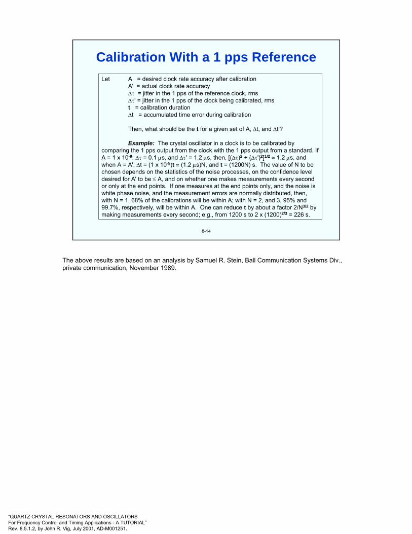
“QUARTZ CRYSTAL RESONATORS AND OSCILLATORSFor Frequency Control and Timing Applications - A TUTORIAL”Rev. 8.5.1.2, by John R. Vig, July 2001, AD-M001251.
8-14
Let A = desired clock rate accuracy after calibrationA' = actual clock rate accuracy∆τ = jitter in the 1 pps of the reference clock, rms∆τ' = jitter in the 1 pps of the clock being calibrated, rmst = calibration duration∆t = accumulated time error during calibration
Then, what should be the t for a given set of A, ∆t, and ∆t'?
Example: The crystal oscillator in a clock is to be calibrated by comparing the 1 pps output from the clock with the 1 pps output from a standard. If A = 1 x 10⁻⁹; ∆τ = 0.1 µs, and ∆τ' = 1.2 µs, then, [(∆τ)2 + (∆τ')2]1/2 ≈ 1.2 µs, and when A = A', ∆t = (1 x 10⁻⁹)t ≡ (1.2 µs)N, and t = (1200N) s. The value of N to be chosen depends on the statistics of the noise processes, on the confidence level desired for A' to be ≤ A, and on whether one makes measurements every second or only at the end points. If one measures at the end points only, and the noise is white phase noise, and the measurement errors are normally distributed, then, with N = 1, 68% of the calibrations will be within A; with N = 2, and 3, 95% and 99.7%, respectively, will be within A. One can reduce t by about a factor 2/N3/2 by making measurements every second; e.g., from 1200 s to 2 x (1200)2/3 = 226 s.
Calibration With a 1 pps Reference
The above results are based on an analysis by Samuel R. Stein, Ball Communication Systems Div., private communication, November 1989.

“QUARTZ CRYSTAL RESONATORS AND OSCILLATORSFor Frequency Control and Timing Applications - A TUTORIAL”Rev. 8.5.1.2, by John R. Vig, July 2001, AD-M001251.
8-15
MethodPortable Cs clock
GPS time disseminationGPS common view
Two-way via satellite
Loran-C
HF (WWV)
Portable quartz & Rbclocks
Accuracy10 - 100 ns
20 - 100 ns5 - 20 ns
~1 ns
100 ns
2 ms
Calibration intervaldependent
~ Cost (‘95)$45K - 70K
$100 - 5K
$60k
$1K - 5K
$100 - 5K
$200 - 2K
Time Transfer Methods
Time-transfer techniques provide a method of maintaining synchronization among remote locations which complements the use of independent clocks. In fact, most systems derive time using both external time references and internal clocks. The former provide long-term accuracy and interoperability; the latter provide autonomous capability in the absence of the external references. A variety of time-transfer techniques are in use today. They vary in capability from a few milliseconds to a few nanoseconds. GPS, and the GPS common view technique, are discussed in the following pages.
Radio broadcast services, such as WWV and WWVB in the United States, disseminate time with modest accuracy. The high-frequency broadcasts between 2.5 and 20 MHz are usually received after reflection from the ionosphere. As a result, variability in the path delay limits the accuracy to a few milliseconds for most users.
The highest accuracy time-synchronization is obtained via two-way satellite techniques. Both the propagation errors and the delays through the receiver are calibrated by transmitting time in both directions between two sites. Each site measures the difference between the time of arrival of the pulse from the other site and the time of the local clock. The difference in the measurements made at the two ends provides the relative time of the two local clocks. The effects of the transmitter and receiver delays, the uplink and downlink propagation delays, and the delays through the satellite are substantially canceled. As a result, time-synchronization accuracy of a few nanoseconds has been obtained using commercial communication satellites and very small aperture terminals (VSAT). A custom spread-spectrum time-transfer modem is necessary.
W. Lewandowski & C. Thomas, “GPS Time Transfer,” Proc. IEEE, vol. 79, pp. 991-1000, 1991.
D. Kirchner, “Two-way Time Transfer Via Communcations Satellites,” Proc. IEEE, vol. 79, pp. 983-990, 1991.
S. Leschiutta, “Time Synchronization Using Laser Techniques,” Proc. IEEE, vol. 79, pp. 1001-1008, 1991.

“QUARTZ CRYSTAL RESONATORS AND OSCILLATORSFor Frequency Control and Timing Applications - A TUTORIAL”Rev. 8.5.1.2, by John R. Vig, July 2001, AD-M001251.
8-16
GPS Nominal Constellation:24 satelites in 6 orbital planes,
4 satelites in each plane,20,200 km altitude, 55 degree inclinations
Global Positioning System (GPS)
The Global Positioning System (GPS) is the most precise worldwide navigation system available. It is also capable of providing nanosecond-level timing accuracies, so, it is also one of the most accurate time sources.
GPS is a satellite-based radio navigation and positioning system that is designed to provide global, all-weather, 24-hour, accurate navigation to an unlimited number of users. Each of the satellites contain atomic clocks. The satellites transmit a navigation message that provides satellite position, time, and atmospheric propagation correction data. The GPS receiver, which contains a quartz crystal clock, measures the transit time of the satellite signal and multiplies that time by the speed of light to compute range to the satellite. The satellite clocks are more accurate than the receiver clocks. Therefore, although three satellites can provide latitude, longitude and altitude, the signal from a fourth satellite is used to correct for the navigational error caused by the receiver clock's inaccuracy, i.e., the receivers calculate their x, y, z, and t from receiving each of four satellites’ x, y, z, and t. Velocity is determined from the Doppler shifts of the the transmitted carrier frequencies.
A. J. Van Dierendonck and M. Birnbaum, "Time Requirements in the NAVSTAR Global Positioning System (GPS)," Proc. 30th Annual Symposium on Frequency Control, pp. 375-383, 1976, AD046089.
F. E. Butterfield, "Frequency Control and Time Information in the NAVSTAR/Global Positioning System," Proc. 30th Annual Symposium on Frequency Control, pp. 371-374, 1976, AD046089
Much information is available on the Internet, e.g., see “Navstar GPS Internet Connections” at http://gauss.gge.unb.ca/GPS.INTERNET.SERVICES.HTML, and “Global Positioning System Overview” by Peter H. Dana (from which the above illustration was “borrowed,” with permission from Peter H. Dana, The University of Texas at Austin) at http://www.utexas.edu/depts/grg/gcraft/notes/gps/gps.html

“QUARTZ CRYSTAL RESONATORS AND OSCILLATORSFor Frequency Control and Timing Applications - A TUTORIAL”Rev. 8.5.1.2, by John R. Vig, July 2001, AD-M001251.
8-17
GPS can provide global, all-weather, 24-hour, real-time, accurate navigation and time reference to an unlimited number of users.
• GPS Accuracies (2σ)
Position: 120 m for Standard Positioning Service, SPS40 m for Precise Positioning Service, PPS1 cm + 1ppm for differential, static land survey
Velocity: 0.3 m/s (SPS), 0.1 m/s (PPS). Time: 350 ns to < 10 ns
• 24 satellites in 6 orbital planes; 6 to 10 visible at all times; ~12 h period 20,200 km orbits.
• Pseudorandom noise (PRN) navigation signals are broadcast at L1 =1.575 GHz (19 cm) and L2 = 1.228 GHz (24 cm); two codes, C/A andP are sent; messages provide satellite position, time, and atmosphericpropagation data; receivers select the optimum 4 (or more) satellites totrack. PPS (for DoD users) uses L1 and L2, SPS uses L1 only.
GPS
GPS may also be used in a differential mode, often called common view, to provide improved synchronization capability. For sites located within several thousand kilometers (km) of one another, timing errors due to errors in the ephemeris and the propagation delay are approximately equal. Thus, when the absolute GPS times of arrival of simultaneously observed satellite signals are subtracted from one another, the differential accuracy can be improved to ~ten nanoseconds.
W. Lewandowski and C. Thomas, "GPS Time Transfer," Proc. IEEE, Vol. 79, pp. 991-1000, July 1991.
C. Fox and S. R. Stein, "GPS Time Determination and Dissemination," Tutorials from the Twenty-third Ann. Precise Time and Time Interval (PTTI) Applications and Planning Meeting, 1991, NTIS Accession No. AD-A254745
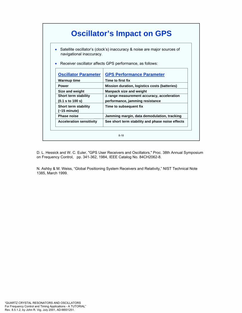
“QUARTZ CRYSTAL RESONATORS AND OSCILLATORSFor Frequency Control and Timing Applications - A TUTORIAL”Rev. 8.5.1.2, by John R. Vig, July 2001, AD-M001251.
8-18
• Satellite oscillator’s (clock’s) inaccuracy & noise are major sources of navigational inaccuracy.
• Receiver oscillator affects GPS performance, as follows:
Oscillator Parameter GPS Performance ParameterWarmup time Time to first fixPower Mission duration, logistics costs (batteries)Size and weight Manpack size and weightShort term stability ∆ range measurement accuracy, acceleration(0.1 s to 100 s) performance, jamming resistanceShort term stability Time to subsequent fix(~15 minute)Phase noise Jamming margin, data demodulation, trackingAcceleration sensitivity See short term stability and phase noise effects
Oscillator’s Impact on GPS
D. L. Hessick and W. C. Euler, "GPS User Receivers and Oscillators," Proc. 38th Annual Symposium on Frequency Control, pp. 341-362, 1984, IEEE Catalog No. 84CH2062-8.
N. Ashby & M. Weiss, “Global Positioning System Receivers and Relativity,” NIST Technical Note 1385, March 1999.

“QUARTZ CRYSTAL RESONATORS AND OSCILLATORSFor Frequency Control and Timing Applications - A TUTORIAL”Rev. 8.5.1.2, by John R. Vig, July 2001, AD-M001251.
8-19
• A "time scale" is a system of assigning dates, i.e., a "time," to events; e.g., 6 January 1989, 13 h, 32 m, 46.382912 s, UTC, is a date.
• A "time interval" is a "length" of time between two events; e.g., five seconds.
• Universal time scales, UT0, UT1, and UT2, are based on the earth's spin on itsaxis, with corrections.
• Celestial navigation: clock (UT1) + sextant position.
• International Atomic Time (TAI) is maintained by the International Bureau ofWeights and Measures (BIPM; in France), and is derived from an ensemble of more than 200 atomic clocks, from more than 60 laboratories around the world.
• Coordinated Universal Time (UTC) is the time scale today, by internationalagreement. The rate of UTC is determined by TAI, but, in order to not let the time vs. the earth's position change indefinitely, UTC is adjusted by means of leap seconds so as to keep UTC within 0.9 s of UT1.
Time Scales
UTC is generated (~30 days) after the fact, by The Bureau International des Poids et Mesuresnear Paris, France, by taking the times of about 230 (as of 1999) of the best (atomic) clocks in the timing laboratories of the world and combining their readings in an optimum way. Each of the 230 clocks receives a weighting factor, depending on its performance. More than 30 countries’ laboratories contribute time data to UTC.
The length of the second is determined by evaluations of 11 laboratory Cs primary frequency standards (located in six countries). A weighted combination is used to make the best estimate of the second.
The time scale generated from combining the 230 clocks and 11 primary standards is called the Temps Atomique International, TAI, i.e., the International Atomic Time. The source of the “second” is the 11 primary standards, and the 230 clocks are the flywheel that maintain the calibration provided by the primary standards.
To obtain real-time estimates of UTC, timing centers around the world generate their own current best estimate of UTC. These are called UTC(k), where k is usually the name of the timing center, e.g., UTC(NIST), UTC(USNO), etc. The BIPM distributes a monthly bulletin which reports all the UTC - UTC(k) for the previous month.
GPS time is not adjusted for leap seconds. It is steered to agree with UTC, except for an integer number of seconds. Except for the leap seconds, GPS time is within 40 ns of UTC. UTC, as estimated by the USNO, is available from the GPS signal.
T. J. Quinn, “The BIPM and the Accurate Measurement of Time,” Proc. IEEE, vol. 79, pp. 894-905, 1991.
D. B. Sullivan, “Time Generation and Distribution,” Proc. IEEE, vol. 79, pp. 906-914, 1991.
D. D. McCarthy, “Astronomical Time,” Proc. IEEE, vol. 79, pp. 915-920, 1991.
The Science of Timekeeping, Hewlett-Packard Co. Application Note 1289
<http://www.tmo.hp.com/tmo/Notes/English/>

“QUARTZ CRYSTAL RESONATORS AND OSCILLATORSFor Frequency Control and Timing Applications - A TUTORIAL”Rev. 8.5.1.2, by John R. Vig, July 2001, AD-M001251.
8-20
• An ensemble of clocks is a group of clocks in which the time outputs of individual clocks are combined, via a “time-scale algorithm,” to form a time scale.
• Ensembles are often used in mission critical applications where a clock’s failure (or degraded performance) presents an unacceptable risk.
• Advantages of an ensemble:- system time & frequency are maintained even if a clock in the ensemble fails
- ensemble average can be used to estimate the characteristics ofeach clock; outliers can be detected
- performance of ensemble can (sometimes) be better than any ofthe contributors
- a proper algorithm can combine clocks of different characteristics, and different duty cycles, in an optimum way
Clock Ensembles and Time Scales
P. Tavella & C. Thomas, “Comparative Study of Time Scale Algorithms,” Metrologia, vol. 28, pp. 57-63, 1991.
C. Thomas, “Impact of New Clock Technologies on the Stability and Accuracy of the International Atomic Time TAI,” Proc. 1996 IEEE Int’l Frequency Control Symposium, pp. 1123-1130, 1996.
Kamas, George and Michael A. Lombardi, Time & Frequency Users' Manual, NIST Special Publication 559, revised 1990.

“QUARTZ CRYSTAL RESONATORS AND OSCILLATORSFor Frequency Control and Timing Applications - A TUTORIAL”Rev. 8.5.1.2, by John R. Vig, July 2001, AD-M001251.
8-21
• Time is not absolute. The "time" at which a distant event takesplace depends on the observer. For example, if two events, A andB, are so close in time or so widely separated in space that nosignal traveling at the speed of light can get from one to the otherbefore the latter takes place, then, even after correcting for propagation delays, it is possible for one observer to find that Atook place before B, for a second to find that B took place before A, and for a third to find that A and B occurred simultaneously. Although it seems bizarre, all three can be right.
• Rapidly moving objects exhibit a "time dilation" effect. (“Twin paradox”: Twin on a spaceship moving at 0.87c will age 6 months while twin on earth ages 1 year. There is no "paradox" because spaceship twin must accelerate; i.e., there is no symmetry to the problem.)
• A clock's rate also depends on its position in a gravitational field. Ahigh clock runs faster than a low clock.
Relativistic Time
N. Ashby & M. Weiss, “Global Positioning System Receivers and Relativity,” NIST Technical Note 1385, March 1999.
C. Alley, "Relativity and Clocks," Proc. 33rd Annual Symposium on Frequency Control, pp. 4-39, 1979.
G. M. R. Winkler, “Synchronization and Relativity,” Proc. IEEE, vol. 79, pp. 1029-1039, 1991.
The Science of Timekeeping, Hewlett-Packard Co. Application Note 1289<http://www.tmo.hp.com/tmo/Notes/English/>
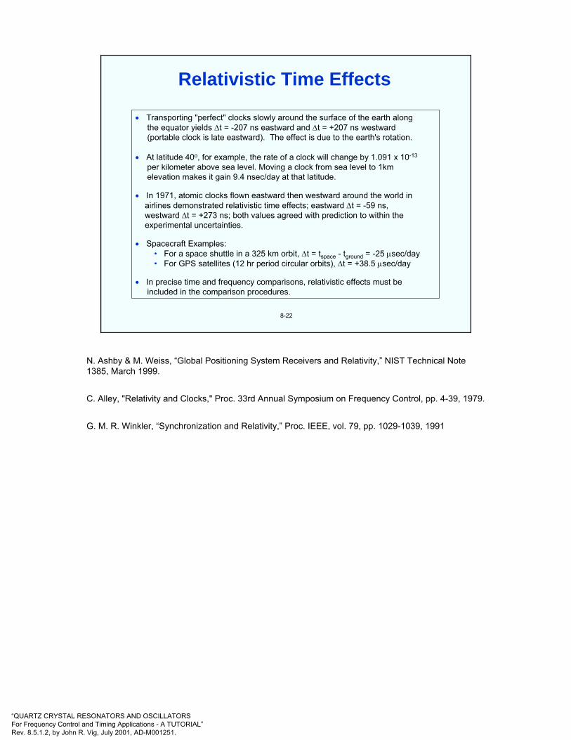
“QUARTZ CRYSTAL RESONATORS AND OSCILLATORSFor Frequency Control and Timing Applications - A TUTORIAL”Rev. 8.5.1.2, by John R. Vig, July 2001, AD-M001251.
8-22
• Transporting "perfect" clocks slowly around the surface of the earth alongthe equator yields ∆t = -207 ns eastward and ∆t = +207 ns westward (portable clock is late eastward). The effect is due to the earth's rotation.
• At latitude 40o, for example, the rate of a clock will change by 1.091 x 10⁻¹³
per kilometer above sea level. Moving a clock from sea level to 1kmelevation makes it gain 9.4 nsec/day at that latitude.
• In 1971, atomic clocks flown eastward then westward around the world inairlines demonstrated relativistic time effects; eastward ∆t = -59 ns,westward ∆t = +273 ns; both values agreed with prediction to within the experimental uncertainties.
• Spacecraft Examples: • For a space shuttle in a 325 km orbit, ∆t = tspace - tground = -25 µsec/day • For GPS satellites (12 hr period circular orbits), ∆t = +38.5 µsec/day
• In precise time and frequency comparisons, relativistic effects must be included in the comparison procedures.
Relativistic Time Effects
N. Ashby & M. Weiss, “Global Positioning System Receivers and Relativity,” NIST Technical Note 1385, March 1999.
C. Alley, "Relativity and Clocks," Proc. 33rd Annual Symposium on Frequency Control, pp. 4-39, 1979.
G. M. R. Winkler, “Synchronization and Relativity,” Proc. IEEE, vol. 79, pp. 1029-1039, 1991

“QUARTZ CRYSTAL RESONATORS AND OSCILLATORSFor Frequency Control and Timing Applications - A TUTORIAL”Rev. 8.5.1.2, by John R. Vig, July 2001, AD-M001251.
8-23
The following expression accounts for relativistic effects, provides for clock rate accuracies of better than 1 part in 1014, and allows for global-scale clock comparisons of nanosecond accuracy, via satellites:
Where ∆t = time difference between spacecraft clock and ground clock, tS-TgVS = spacecraft velocity (<<c), Vg = velocity of ground station
ΦS = gravitational potential at the spacecraftΦg = gravitational potential at the ground stationω = angular velocity of rotation of the earthAE = the projected area on the earth’s equatorial plane swept out by the vector
whose tail is at the center of the earth and whose head is at the position of the portable clock or the electromagnetic signal pulse. The AE is taken positive if the head of the vector moves in the eastward direction.
Within 24 km of sea level, Φ = gh is accurate to 1 x 10-14 where g = (9.780 + 0.052 sin2Ψ )m/s2, Ψ = the latitude, h = the distance above sea level, and where the sin2Ψterm accounts for the centrifugal potential due to the earth's rotation. The "Sagnac effect," (2ω/c2)AE = (1.6227 x 10⁻²¹s/m2)AE, accounts for the earth-fixed coordinate system being a rotating, noninertial reference frame.
( ) ( ) E2
T
0gS
2g
2s2 A
cdtvv
ct 2
211 ω∆ +⎥⎦
⎤⎢⎣⎡ Φ−Φ−−−= ∫
Relativistic Time Corrections
N. Ashby and D. W. Allan, "Practical Implications of Relativity for a Global Coordinate Time Scale," Radio Science, Vol. 14, No. 4, pp. 649-669, July-August 1979.
C. Alley, "Relativity and Clocks," Proc. 33rd Annual Symposium on Frequency Control, pp. 4-39, 1979.
G. M. R. Winkler, “Synchronization and Relativity,” Proc. IEEE, vol. 79, pp. 1029-1039, 1991.
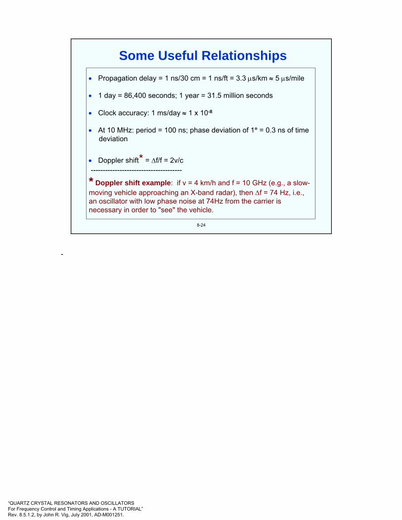
“QUARTZ CRYSTAL RESONATORS AND OSCILLATORSFor Frequency Control and Timing Applications - A TUTORIAL”Rev. 8.5.1.2, by John R. Vig, July 2001, AD-M001251.
8-24
• Propagation delay = 1 ns/30 cm = 1 ns/ft = 3.3 µs/km ≈ 5 µs/mile
• 1 day = 86,400 seconds; 1 year = 31.5 million seconds
• Clock accuracy: 1 ms/day ≈ 1 x 10⁻⁸
• At 10 MHz: period = 100 ns; phase deviation of 1° = 0.3 ns of timedeviation
• Doppler shift* = ∆f/f = 2v/c --------------------------------------
* Doppler shift example: if v = 4 km/h and f = 10 GHz (e.g., a slow-moving vehicle approaching an X-band radar), then ∆f = 74 Hz, i.e., an oscillator with low phase noise at 74Hz from the carrier is necessary in order to "see" the vehicle.
Some Useful Relationships
-

“QUARTZ CRYSTAL RESONATORS AND OSCILLATORSFor Frequency Control and Timing Applications - A TUTORIAL”Rev. 8.5.1.2, by John R. Vig, July 2001, AD-M001251.
8-25
"The leading edge of the BCD code (negative going transitions after extended high level) shall coincide with the on-time (positive going transition) edge of the one pulse-per-second signal to within ±1 millisecond." See next page for the MIL-STD BCD code.
10 Volts(± 10%)
0 Volts(± 1 Volt
Rise Time< 20 Nanoseconds
Fall Time< 1 Microseconds
20 µsec ± 5%
One Pulse-Per-Second Timing Signal(MIL-STD-188-115)
MIL-STD-188-115, Military Standard, "Interoperability and Performance Standards for Communications Timing and Synchronization Subsystems," 31 March 1986. Copies are available from Naval Publications and Forms Center, 5801 Tabor Ave., Philadelphia, PA 19120
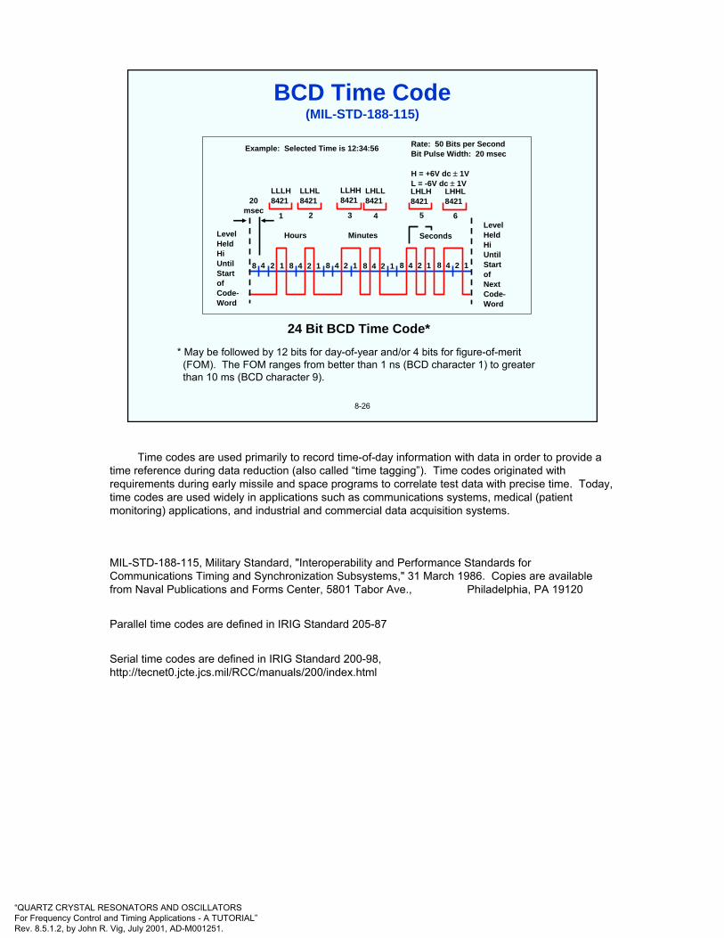
“QUARTZ CRYSTAL RESONATORS AND OSCILLATORSFor Frequency Control and Timing Applications - A TUTORIAL”Rev. 8.5.1.2, by John R. Vig, July 2001, AD-M001251.
8-26
24 Bit BCD Time Code** May be followed by 12 bits for day-of-year and/or 4 bits for figure-of-merit
(FOM). The FOM ranges from better than 1 ns (BCD character 1) to greater than 10 ms (BCD character 9).
LevelHeldHiUntilStartofNextCode-Word
Example: Selected Time is 12:34:56
LevelHeldHiUntilStartofCode-Word
20msec
LLLH8421
LLHL8421
LLHH8421
LHLL8421
LHLH8421
LHHL8421
Hours Minutes Seconds
1 2 3 4 5 6
Rate: 50 Bits per SecondBit Pulse Width: 20 msec
H = +6V dc ± 1VL = -6V dc ± 1V
8 4 2 1 8 4 2 1 8 4 2 1 8 4 2 1 8 4 2 1 8 4 2 1
BCD Time Code(MIL-STD-188-115)
Time codes are used primarily to record time-of-day information with data in order to provide a time reference during data reduction (also called “time tagging”). Time codes originated with requirements during early missile and space programs to correlate test data with precise time. Today, time codes are used widely in applications such as communications systems, medical (patient monitoring) applications, and industrial and commercial data acquisition systems.
MIL-STD-188-115, Military Standard, "Interoperability and Performance Standards for Communications Timing and Synchronization Subsystems," 31 March 1986. Copies are available from Naval Publications and Forms Center, 5801 Tabor Ave., Philadelphia, PA 19120
Parallel time codes are defined in IRIG Standard 205-87
Serial time codes are defined in IRIG Standard 200-98, http://tecnet0.jcte.jcs.mil/RCC/manuals/200/index.html

“QUARTZ CRYSTAL RESONATORS AND OSCILLATORSFor Frequency Control and Timing Applications - A TUTORIAL”Rev. 8.5.1.2, by John R. Vig, July 2001, AD-M001251.
8-27
Oscillator and Clock DriverOscillator and Clock Driver
PowerSourcePowerSource
Time CodeGeneratorTime CodeGenerator
FrequencyDistributionFrequencyDistribution
f1 f2 f3 TOD 1 pps
Time and Frequency Subsystem
The time and frequency subsystem, also sometimes called a “time and frequency unit (TFU) provides frequencies and time to a system.

“QUARTZ CRYSTAL RESONATORS AND OSCILLATORSFor Frequency Control and Timing Applications - A TUTORIAL”Rev. 8.5.1.2, by John R. Vig, July 2001, AD-M001251.
8-28
* The microcomputer compensates for systematic effects (after filtering random effects), and performs: automatic synchronization and calibration when an external reference is available, and built-in-testing.
ExternalReferenceExternal
Reference
Oscillator/Clock-DriverOscillator/
Clock-Driver
MicrocomputerCompensation and
Control
MicrocomputerCompensation and
Control
FrequencyDistributionFrequency
DistributionClock andTime codeGenerator
Clock andTime codeGenerator
BatteryBattery
DC-DCConverterDC-DC
Converter
>
Vin
V1V2
f1 f2 f3 TOD 1pps
The MIFTTI SubsystemMIFTTI = Modular Intelligent Frequency, Time and Time
Interval
Time and frequency subsystems can include built-in intelligence to improve performance, as was shown in the MIFFTI development program. Intelligence was used to achieve maximum time and frequency performance from the available frequency sources by providing automatic fault detection, synchronization and syntonization, and by providing compensation for such systematic errors such as short-term aging and temperature sensitivity.
Clocks and timing receivers can be combined in a timing system to provide a broader range of timing capabilities than either one can provide alone. Such a system uses the received timing signal to calibrate the local clock, and learn its time, frequency, and frequency aging. When the timing signal is unavailable, the local clock acts as a "flywheel." Its free-running operation starts using the time and frequency provided by calibration versus the external source. The frequency may subsequently be updated periodically for the predicted frequency aging. This procedure produces the minimum possible free-running timing errors. Commercial "disciplined oscillators" now provide these functions in an integrated package.
K.D. Lyon, W.J. Riley, and J.R. Vaccaro, “The Modular Intelligent Frequency, Time And Time Interval (MIFTTI) Subsystem Program,” Proc. 43rd Ann. Frequency Control Symp., pp. 225-231, 1989.
S. R. Stein & R. L. Filler, “Kalman Filter Analysis for Real Time Applications of Clocks and Oscillators, Proc. 42nd Ann. Frequency Control Symp., pp. 447-452, 1988.
S. R. Stein and J. R. Vig, "Frequency Standards for Communications," U. S. Army Laboratory Command Research and Development Technical Report SLCET-TR-91-2 (Rev. 1), October 1991, AD-A243211. This report is a reprint of a chapter "Communications Frequency Standards," in The Froehlich/Kent Encyclopedia of Telecommunications, Vol. 3, pp. 445-500, Marcel Dekker, Inc., 1992.

“QUARTZ CRYSTAL RESONATORS AND OSCILLATORSFor Frequency Control and Timing Applications - A TUTORIAL”Rev. 8.5.1.2, by John R. Vig, July 2001, AD-M001251.
8-29
3 o'clock is always too late or too early for anything you want to do..................Jean-Paul SartreTime ripens all things. No man's born wise............Cervantes. Time is the rider that breaks youth............George Herbert Time wounds all heels..................Jane AceTime heals all wounds..................Proverb The hardest time to tell: when to stop.....Malcolm ForbesTime is on our side..................William E. Gladstone It takes time to save time.............Joe TaylorTime, whose tooth gnaws away everything else, is powerless against truth..................Thomas H. HuxleyTime has a wonderful way of weeding out the trivial..................Richard Ben Sapir Time is a file that wears and makes no noise...........English proverb The trouble with life is that there are so many beautiful women - and so little time..................John BarrymoreLife is too short, and the time we waste yawning can never be regained..................StendahlTime goes by: reputation increases, ability declines..................Dag HammarskjöldRemember that time is money...............Benjamin FranklinTime is money - says the vulgarest saw known to any age or people. Turn it around, and you get a precious truth -Money is time..................George (Robert) Gissing
The butterfly counts not months but moments, and has time enough..................Rabindranath TagoreEverywhere is walking distance if you have the time..................Steven WrightThe only true time which a man can properly call his own, is that which he has all to himself; the rest, though insome sense he may be said to live it, is other people's time, not his..................Charles LambIt is familiarity with life that makes time speed quickly. When every day is a step in the unknown, as for children, thedays are long with gathering of experience..................George GissingTime is a great teacher, but unfortunately it kills all its pupils..................Hector BerliozTo everything there is a season, and a time to every purpose under the heaven..................Ecclesiastes 3:1Time goes, you say? Ah no! Time stays, we go..................Henry Austin Dobson
"Time" Quotations
Man must sit in chair with mouth open for very long time before roast duck fly in. - Chinese Proverb
The time to repair the roof is when the sun is shining. - John F. Kennedy
There may be times when we are powerless to prevent injustice, but there must never be a time when we fail to protest. - Elie Wiesel
The time to win a fight is before it starts. - Frederick W. Lewis
Nothing is a waste of time if you use the experience wisely. - Auguste Rodin
There is one thing stronger than all the armies in the world, and that is an idea whose time has come. - Victor Hugo
We didn't lose the game; we just ran out of time. - Vince Lombardi
I have made this letter longer because I lack the time to make it shorter. - Blaise Pascal
Begin to make the kind of investment of personal time which will assure that those who come after us will live as well. - Charles W. Bray III
Most of us spend too much time on the last twenty-four hours and too little on the last six thousand years. - Will Durant
Don't spend your precious time asking 'Why isn't the world a better place?” It will only be time wasted. The question to ask is 'How can I make it better?' To that there is an answer. -Leo F. Buscaglia
In Germany they came first for the Communists, and I didn't speak up because I wasn't a Communist. Then they came for the Jews, and I didn't speak up because I wasn't a Jew. Then they came for the trade unionists, and I didn't speak up because I wasn't a trade unionist. Then they came for the Catholics, and I didn't speak up because I was a
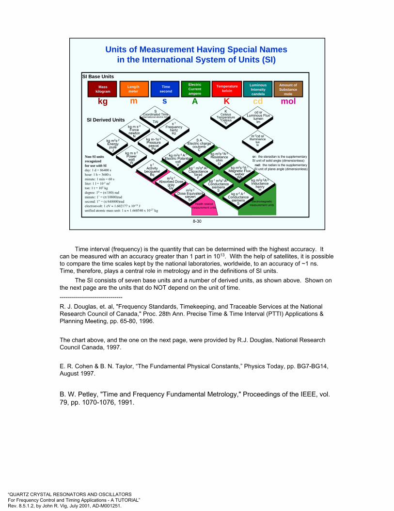
“QUARTZ CRYSTAL RESONATORS AND OSCILLATORSFor Frequency Control and Timing Applications - A TUTORIAL”Rev. 8.5.1.2, by John R. Vig, July 2001, AD-M001251.
SI Base Units
Masskilogram
Lengthmeter
Timesecond
ElectricCurrentampere
LuminousIntensitycandela
kg m s A
Temperaturekelvin
K cd
Amount ofSubstance
mole
mol
SI Derived Units
kg m2s-2
Energyjoule
Jkg m s-3
PowerwattW s-1
Activitybecquerel
Bqm2s-1
Absorbed DosegrayGy m2s-2
Dose Equivalentsievert
Sv
kg m s-2
Forcenewton
Nkg m-1s-2
Pressurepascal
Pa
kg m2s-3 A-1
Electric PotentialvoltV
kg-1 m2s4 A2
Capacitancefarad
Fkg-1 m2s3 A2
Conductancesiemens
Skg s-2 A-1
Conductancesiemens
S
SCoordinated Time
international atomic time
TAI s-1
FrequencyhertzHz
S AElectric charge
coulombC
kg m2s-3A-2
Resistanceohm
Ωkg m2s-2A-1
Magnetic Fluxweber
Wbkg m2s-2A-2
Inductancehenry
H
KCelsius
Temperature0Celsius
0C
cd srLuminous Flux
lumenlm
m-2cd srIlluminance
luxlx
sr: the steradian is the supplementarySI unit of solid angle (dimensionless)
rad: the radian is the supplementarySI unit of plane angle (dimensionless)
Electromagneticmeasurement unitsHealth related
measurement units
Non-SI unitsrecognizedfor use with SIday: 1 d = 86400 shour: 1 h = 3600 sminute: 1 min = 60 sliter: 1 l = 10-3 m3
ton: 1 t = 103 kgdegree: 10 = (π/180) radminute: 1’ = (π/10800)radsecond: 1” = (π/648000)radelectronvolt: 1 eV ≈ 1.602177 x 10⁻¹⁹ Junified atomic mass unit: 1 u ≈ 1.660540 x 10⁻²⁷ kg
8-30
Units of Measurement Having Special Namesin the International System of Units (SI)
Time interval (frequency) is the quantity that can be determined with the highest accuracy. It can be measured with an accuracy greater than 1 part in 1013. With the help of satellites, it is possible to compare the time scales kept by the national laboratories, worldwide, to an accuracy of ~1 ns. Time, therefore, plays a central role in metrology and in the definitions of SI units.
The SI consists of seven base units and a number of derived units, as shown above. Shown on the next page are the units that do NOT depend on the unit of time.-------------------------------R. J. Douglas, et. al, "Frequency Standards, Timekeeping, and Traceable Services at the National Research Council of Canada," Proc. 28th Ann. Precise Time & Time Interval (PTTI) Applications & Planning Meeting, pp. 65-80, 1996.
The chart above, and the one on the next page, were provided by R.J. Douglas, National Research Council Canada, 1997.
E. R. Cohen & B. N. Taylor, “The Fundamental Physical Constants,” Physics Today, pp. BG7-BG14, August 1997.
B. W. Petley, "Time and Frequency Fundamental Metrology," Proceedings of the IEEE, vol. 79, pp. 1070-1076, 1991.

“QUARTZ CRYSTAL RESONATORS AND OSCILLATORSFor Frequency Control and Timing Applications - A TUTORIAL”Rev. 8.5.1.2, by John R. Vig, July 2001, AD-M001251.
SI Base Units
Masskilogram
kg
Temperaturekelvin
K
Amount ofSubstance
mole
molK
CelsiusTemperature
0Celsius0C
SI Derived Units
ton: 1 t = 103 kgdegree: 10 = (π/180) radminute: 1’ = (π/10800)radsecond: 1” = (π/648000)radunified atomic mass unit: 1 u ≈ 1.660540 x 10⁻²⁷ kg
Non-SI unitsrecognizedfor use with SI
8-31
Units of Measurement Having Special Names in the SI Units, NOT Needing Standard Uncertainty in SI Average Frequency
-

“QUARTZ CRYSTAL RESONATORS AND OSCILLATORSFor Frequency Control and Timing Applications - A TUTORIAL”Rev. 8.5.1.2, by John R. Vig, July 2001, AD-M001251.
9
CHAPTER 9Related Devices and Application
-

“QUARTZ CRYSTAL RESONATORS AND OSCILLATORSFor Frequency Control and Timing Applications - A TUTORIAL”Rev. 8.5.1.2, by John R. Vig, July 2001, AD-M001251.
9-1
Layout
Circuit
Discrete-Resonator Crystal FilterA Typical Six-pole Narrow-band Filter
Most crystal filters are bandpass filters. There are two types, one which consists of discreet resonators, as illustrated above, and the other, monolithic crystal filters which consist of acoustically coupled resonators, as illustrated on the next page.
R. C. Smythe and R. S. Wagers, "Piezoelectric and Electromechanical Filters," in E. A. Gerber and A. Ballato, Precision Frequency Control, Vol. 1, pp. 185-269, Academic Press, 1985.
R. G. Kinsman, Crystal Filters, John Wiley & Sons, 1987.

“QUARTZ CRYSTAL RESONATORS AND OSCILLATORSFor Frequency Control and Timing Applications - A TUTORIAL”Rev. 8.5.1.2, by John R. Vig, July 2001, AD-M001251.
9-2
25.0
20.0
15.0
10.0
5.0
0Frequency
Atte
nuat
ion
(dB
)Four-pole filter
electrode arrangement
Two-pole filter and its response
Monolithic Crystal Filters
R. C. Smythe and R. S. Wagers, "Piezoelectric and Electromechanical Filters," in E. A. Gerber and A. Ballato, Precision Frequency Control, Vol. 1, pp. 185-269, Academic Press, 1985.
R. G. Kinsman, Crystal Filters, John Wiley & Sons, 1987.
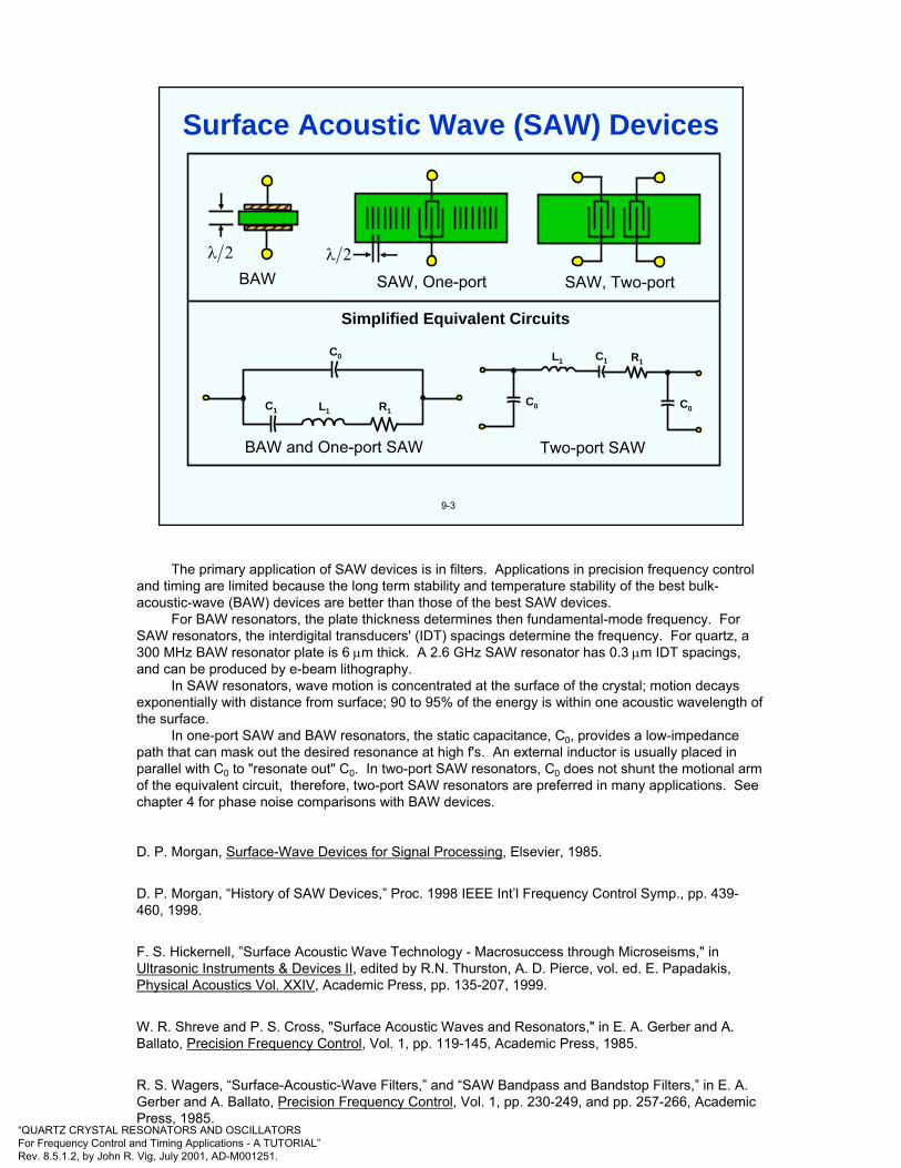
“QUARTZ CRYSTAL RESONATORS AND OSCILLATORSFor Frequency Control and Timing Applications - A TUTORIAL”Rev. 8.5.1.2, by John R. Vig, July 2001, AD-M001251.
9-3
2λBAW
2λ
SAW, One-port SAW, Two-port
Simplified Equivalent Circuits
BAW and One-port SAW
C0
C1 L1 R1
Two-port SAW
C0
L1 C1 R1
C0
Surface Acoustic Wave (SAW) Devices
The primary application of SAW devices is in filters. Applications in precision frequency control and timing are limited because the long term stability and temperature stability of the best bulk-acoustic-wave (BAW) devices are better than those of the best SAW devices.
For BAW resonators, the plate thickness determines then fundamental-mode frequency. For SAW resonators, the interdigital transducers' (IDT) spacings determine the frequency. For quartz, a 300 MHz BAW resonator plate is 6 µm thick. A 2.6 GHz SAW resonator has 0.3 µm IDT spacings, and can be produced by e-beam lithography.
In SAW resonators, wave motion is concentrated at the surface of the crystal; motion decays exponentially with distance from surface; 90 to 95% of the energy is within one acoustic wavelength of the surface.
In one-port SAW and BAW resonators, the static capacitance, C0, provides a low-impedance path that can mask out the desired resonance at high f's. An external inductor is usually placed in parallel with C0 to "resonate out" C0. In two-port SAW resonators, C0 does not shunt the motional arm of the equivalent circuit, therefore, two-port SAW resonators are preferred in many applications. See chapter 4 for phase noise comparisons with BAW devices.
D. P. Morgan, Surface-Wave Devices for Signal Processing, Elsevier, 1985.
D. P. Morgan, “History of SAW Devices,” Proc. 1998 IEEE Int’l Frequency Control Symp., pp. 439-460, 1998.
F. S. Hickernell, ”Surface Acoustic Wave Technology - Macrosuccess through Microseisms," inUltrasonic Instruments & Devices II, edited by R.N. Thurston, A. D. Pierce, vol. ed. E. Papadakis,Physical Acoustics Vol. XXIV, Academic Press, pp. 135-207, 1999.
W. R. Shreve and P. S. Cross, "Surface Acoustic Waves and Resonators," in E. A. Gerber and A. Ballato, Precision Frequency Control, Vol. 1, pp. 119-145, Academic Press, 1985.
R. S. Wagers, “Surface-Acoustic-Wave Filters,” and “SAW Bandpass and Bandstop Filters,” in E. A. Gerber and A. Ballato, Precision Frequency Control, Vol. 1, pp. 230-249, and pp. 257-266, Academic Press, 1985.
“QUARTZ CRYSTAL RESONATORS AND OSCILLATORSFor Frequency Control and Timing Applications - A TUTORIAL”Rev. 8.5.1.2, by John R. Vig, July 2001, AD-M001251.
9-4
In frequency control and timekeeping applications, resonators are designed to have minimum sensitivity to environmental parameters. In sensor applications, the resonator is designed to have a highsensitivity to an environmental parameter, such as temperature, adsorbed mass, force, pressure and acceleration.
Quartz resonators' advantages over other sensor technologies are:
• High resolution and wide dynamic range (due to excellent short-term stability); e.g., one part in 107 (10-6 g out of 20 g) accelerometers are available, and quartz sorption detectors arecapable of sensing 10-12 grams.
• High long-term accuracy and stability, and
• Frequency counting is inherently digital.
Quartz Bulk-Wave Resonator Sensors
D. S. Ballantine, Jr., et. al, Acoustic Wave Sensors - Theory, Design, and Physico-Chemical Applications, Academic Press, 1997.
Special Issue on Sensors and Actuators, IEEE Trans. on Ultrasonics, Ferroelectrics, and Frequency Control, vol. 45, September 1998.
E. P. EerNisse, R. W. Ward and R. B. Wiggins, "Survey of Quartz Bulk Resonator Sensor Technologies," IEEE Transactions on Ultrasonics, Ferroelectrics, and Frequency Control, Vol. 35, No. 3, pp. 323-330, May 1988.
G. G. Guilbault and J. M. Jordan, "Analytical Uses of Piezoelectric Crystals: A Review," CRC Critical Reviews in Analytical Chemistry, Vol. 19, Issue 1, pp. 1-28, 1988.
J. J. McCallum, "Piezoelectric Devices for Mass and Chemical Measurements," Analyst, Vol. 114, pp. 1173-1189, Oct. 1989.
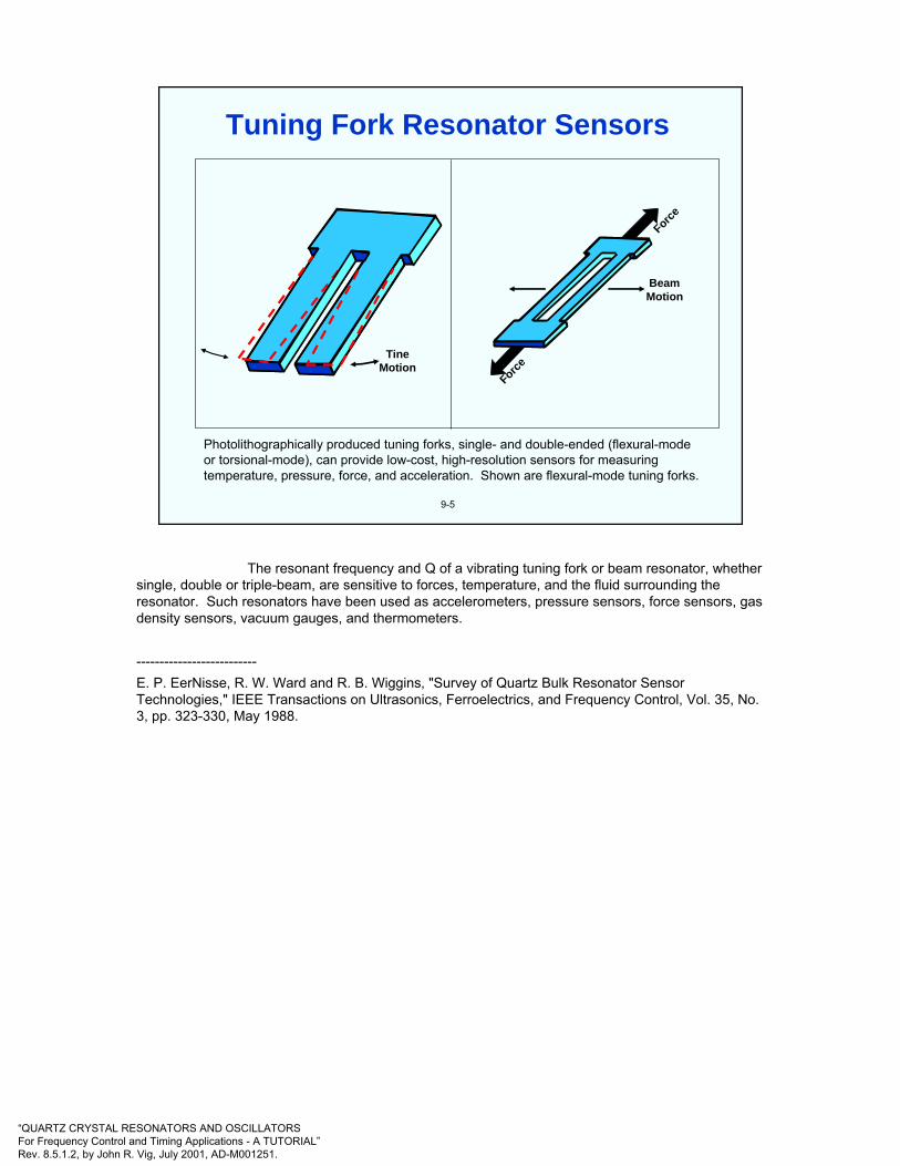
“QUARTZ CRYSTAL RESONATORS AND OSCILLATORSFor Frequency Control and Timing Applications - A TUTORIAL”Rev. 8.5.1.2, by John R. Vig, July 2001, AD-M001251.
9-5
Photolithographically produced tuning forks, single- and double-ended (flexural-mode or torsional-mode), can provide low-cost, high-resolution sensors for measuring temperature, pressure, force, and acceleration. Shown are flexural-mode tuning forks.
TineMotion
Force
Force
BeamMotion
Tuning Fork Resonator Sensors
The resonant frequency and Q of a vibrating tuning fork or beam resonator, whether single, double or triple-beam, are sensitive to forces, temperature, and the fluid surrounding the resonator. Such resonators have been used as accelerometers, pressure sensors, force sensors, gas density sensors, vacuum gauges, and thermometers.
--------------------------E. P. EerNisse, R. W. Ward and R. B. Wiggins, "Survey of Quartz Bulk Resonator Sensor Technologies," IEEE Transactions on Ultrasonics, Ferroelectrics, and Frequency Control, Vol. 35, No. 3, pp. 323-330, May 1988.
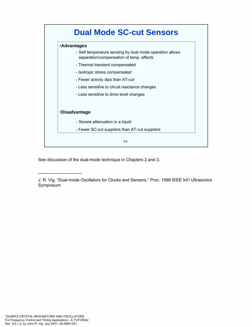
“QUARTZ CRYSTAL RESONATORS AND OSCILLATORSFor Frequency Control and Timing Applications - A TUTORIAL”Rev. 8.5.1.2, by John R. Vig, July 2001, AD-M001251.
Dual Mode SC-cut Sensors•Advantages
- Self temperature sensing by dual mode operation allowsseparation/compensation of temp. effects
- Thermal transient compensated
- Isotropic stress compensated
- Fewer activity dips than AT-cut
- Less sensitive to circuit reactance changes
- Less sensitive to drive level changes
•Disadvantage
- Severe attenuation in a liquid
- Fewer SC-cut suppliers than AT-cut suppliers
9-6
See discussion of the dual-mode technique in Chapters 2 and 3.
------------------------------J. R. Vig, “Dual-mode Oscillators for Clocks and Sensors,” Proc. 1999 IEEE Int’l Ultrasonics Symposium

“QUARTZ CRYSTAL RESONATORS AND OSCILLATORSFor Frequency Control and Timing Applications - A TUTORIAL”Rev. 8.5.1.2, by John R. Vig, July 2001, AD-M001251.
Separation of Mass and Temperature Effects
• Frequency changes
• Mass: adsorption and desorption
• Temperature/beat frequency
effects other etemperatur mass total of
)x(f
of)T(f
of)m(f
of)x,T,m(f ∆
+∆
+∆
=∆
omm
ofmf ∆−≅∆ )(
o
ii
o f
fc
fTf i
∑ ∆⋅=∆ β)( )T(f)T(f3f 3c1c −≡β
9-7
When, for example, a mass is deposited onto a resonator (e.g., a quartz crystal microbalance), there is always a temperature change accompanying the mass change. The temperature change is caused by the heat of adsorption, and by the heat emitted by the evaporation source. The frequency change due to mass deposition is due to the combined effects of the mass change and the temperature change. The dual mode technique yields two equations with two unknowns which allows the separation of the mass change induced frequency change from the temperature caused frequency change.
The mass change alone can be determined without having to calibrate the beat frequency, fβ, as a function of temperature. However, by calibrating the fβ ασ α φυνχτιον οφ τεµπερατυρε, ονε µαψ, φορ εξαµπλε, περφορµ συρφαχε στυδιεσ ασ α φυνχτιον οφ τεµπερατυρε.
--------------------------D. E. Pierce, Y. Kim, and J. R. Vig, "A temperature insensitive quartz microbalance,“ Proc. 1997 IEEE Int’l Frequency Control Symp., pp. 41-48.
J. R. Vig, “Dual-mode Oscillators for Clocks and Sensors,” Proc. 1999 IEEE Int’l Ultrasonics Symposium
US Pat. No. 5869763, J. R. Vig and R. L. Filler, "Method of measuring mass change using a quartz crystal microbalance," Feb. 1999.
Y. Kim, “Sensing of organic vapor adsorption on gold using a temperature insensitive microbalance,” Proc. 1999 IEEE Int’l Frequency Control Symp.

“QUARTZ CRYSTAL RESONATORS AND OSCILLATORSFor Frequency Control and Timing Applications - A TUTORIAL”Rev. 8.5.1.2, by John R. Vig, July 2001, AD-M001251.
End Caps
Electrode
Resonator9-8
Dual-Mode Pressure Sensor
High precision pressure sensors employ quartz thickness shear resonators. The frequencies of these vary not only with pressure, but also with temperature. Temperature control, or compensation is used to minimize the errors due to temperature effects. Some pressure sensors have used a temperature sensor that is external, but in close proximity, to the pressure sensing resonator, and shielded from the applied pressure. However, when a temperature gradient exists between the pressure and temperature sensors, such as may occur under pressure and temperature transients, the accuracy of pressure measurement is degraded.
Dual-mode pressure sensors have been proposed in which the b-mode is stress compensated and the c-mode is temperature compensated. In such a sensor, the b-mode indicates primarily the temperature of the sensing resonator, and the c-mode indicates the applied pressure. As the b-mode’s frequency depends on the temperature of the resonator’s vibrating volume, the effects of temperature gradients are greatly reduced. Under pressure transients, especially, dual-mode pressure sensors allow for superior temperature sensing and compensation accuracy, and superior pressure sensing accuracy. The above diagram shows such a dual mode pressure sensor.
----------------------------R. J. Besson, J. J. Boy, B. Glotin, Y. Jinzaki, B. Sinha, and M. Valdois, “A dual-mode thickness-shear quartz pressure sensor,” IEEE Trans. Ultrason. Ferroelect. Freq. Contr., Vol. 40, pp. 584-591, 1993.
N. Matsumoto, Y. Sudo, B. Sinha and M. Niwa, “Long-term stability and performance characteristics of crystal gauge at high pressures and temperatures,” Proc. 1999 IEEE Int’l Frequency Control Symp.

“QUARTZ CRYSTAL RESONATORS AND OSCILLATORSFor Frequency Control and Timing Applications - A TUTORIAL”Rev. 8.5.1.2, by John R. Vig, July 2001, AD-M001251.
10
CHAPTER 10Proceedings Ordering Information,
Standards, Website, and Index
-
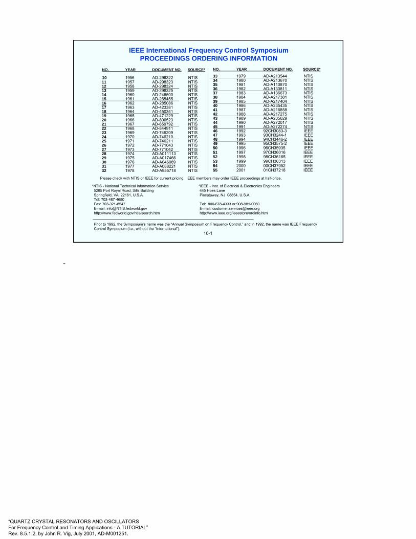
“QUARTZ CRYSTAL RESONATORS AND OSCILLATORSFor Frequency Control and Timing Applications - A TUTORIAL”Rev. 8.5.1.2, by John R. Vig, July 2001, AD-M001251.
10-1
Please check with NTIS or IEEE for current pricing. IEEE members may order IEEE proceedings at half-price.
*NTIS - National Technical Information Service *IEEE - Inst. of Electrical & Electronics Engineers5285 Port Royal Road, Sills Building 445 Hoes LaneSpringfield, VA 22161, U.S.A. Piscataway, NJ 08854, U.S.A.Tel: 703-487-4650Fax: 703-321-8547 Tel: 800-678-4333 or 908-981-0060E-mail: [email protected] E-mail: [email protected]://www.fedworld.gov/ntis/search.htm http://www.ieee.org/ieeestore/ordinfo.html______________________________________________________________________________
Prior to 1992, the Symposium’s name was the “Annual Symposium on Frequency Control,” and in 1992, the name was IEEE Frequency Control Symposium (i.e., without the “International”).
NO. YEAR DOCUMENT NO. SOURCE*
10 1956 AD-298322 NTIS11 1957 AD-298323 NTIS12 1958 AD-298324 NTIS13 1959 AD-298325 NTIS14 1960 AD-246500 NTIS15 1961 AD-265455 NTIS16 1962 AD-285086 NTIS17 1963 AD-423381 NTIS18 1964 AD-450341 NTIS19 1965 AD-471229 NTIS20 1966 AD-800523 NTIS21 1967 AD-659792 NTIS22 1968 AD-844911 NTIS23 1969 AD-746209 NTIS24 1970 AD-746210 NTIS25 1971 AD-746211 NTIS26 1972 AD-771043 NTIS27 1973 AD-771042 NTIS28 1974 AD-A011113 NTIS29 1975 AD-A017466 NTIS30 1976 AD-A046089 NTIS31 1977 AD-A088221 NTIS32 1978 AD-A955718 NTIS
NO. YEAR DOCUMENT NO. SOURCE*
33 1979 AD-A213544 NTIS34 1980 AD-A213670 NTIS35 1981 AD-A110870 NTIS36 1982 AD-A130811 NTIS37 1983 AD-A136673 NTIS38 1984 AD-A217381 NTIS39 1985 AD-A217404 NTIS40 1986 AD-A235435 NTIS41 1987 AD-A216858 NTIS42 1988 AD-A217275 NTIS43 1989 AD-A235629 NTIS44 1990 AD-A272017 NTIS45 1991 AD-A272274 NTIS46 1992 92CH3083-3 IEEE47 1993 93CH3244-1 IEEE48 1994 94CH3446-2 IEEE49 1995 95CH3575-2 IEEE50 1996 96CH35935 IEEE51 1997 97CH36016 IEEE52 1998 98CH36165 IEEE53 1999 99CH36313 IEEE54 2000 00CH37052 IEEE55 2001 01CH37218 IEEE
IEEE International Frequency Control SymposiumPROCEEDINGS ORDERING INFORMATION
-

“QUARTZ CRYSTAL RESONATORS AND OSCILLATORSFor Frequency Control and Timing Applications - A TUTORIAL”Rev. 8.5.1.2, by John R. Vig, July 2001, AD-M001251.
10-2
Institute Of Electrical & Electronic Enggineers (IEEE)
Order from: IEEE Service Center445 Hoes LanePiscataway, NJ 08854
Telephone: (732) 981-0060http://standards.ieee.org/catalog/contents.html
176-1987 (ANSI/IEEE) Standard on Piezoelectricity
177-1966 Standard Definitions & Methods of Measurements of Piezoelectric Vibrators
180-1986 (ANSI/IEEE) Definitions of Primary Ferroelectric Crystal Terms (SH10553)
319-1971 (Reaff 1978) Piezomagnetic Nomenclature (SH02360)
1139-1988 Standard Definitions of Physical Quantities for FundamentalFrequency & Time Metrology (SH12526)
IEEE Std 1193-1994 (ANSI) IEEE Guide for Measurement of Environmental Sensitivities of Standard Frequency Generators
Department of Defense (DOD)
Order from: Naval Pubs & Form Center5801 Tabor AvenuePhiladelphia, PA 19120
Telephone: (215) 697-2000http://www.dscc.dla.mil/Programs/MilSpec/default.asphttp://stinet.dtic.mil/str/dodiss4_fields.html
General Specs for:
MIL-C-3098 Crystal Unit, Quartz
MIL-C-24523 (SHIPS) Chronometer, Quartz Crystal
MIL-F-15733 Filters & Capacitors, Radio Interference
MIL-F-18327 Filters, High Pass, Band Pass Suppression and Dual Processing
MIL-F-28861 Filters and Capacitors, Radio Frequency Electro-magnetic Interference Suppression
MIL-F-28811 Frequency Standard, Cesium Beam Tube
MIL-H-10056 Holders (Encl), Crystal
MIL-O-55310 Oscillators, Crystal MIL-O-39021 Oven
MIL-S-4933(ER) Surface Acoustic Wave Devices
MIL-STD-683 Crystal Units, Quartz/Holders, Crystal
MIL-STD-188-115 Interoperability & Performance Standards for Communications,Timing & Synchron-ization Subsystems
MIL-STD-1395 Filters & Networks, Selection & Use
MIL-T-28816(EC) Time Frequency Standard, Disciplined AN/URQ-23
MIL-W-46374D Watch, wrist: General purpose
MIL-W-87967 Watch, wrist: Digital
Specifications And Standards Relating To Frequency Control - 1
-

“QUARTZ CRYSTAL RESONATORS AND OSCILLATORSFor Frequency Control and Timing Applications - A TUTORIAL”Rev. 8.5.1.2, by John R. Vig, July 2001, AD-M001251.
10-3
US Government Standards
FED-STD-1002 Time & Frequency Reference Information in Telecommunication Systems
FederalFederal StandardStandard 1037C: Glossary of Telecommunications Terms1037C: Glossary of Telecommunications Termshttp://www.its.bldrdoc.gov/fshttp://www.its.bldrdoc.gov/fs--1037/1037/
IRIG IRIG StdrdStdrd 200200--9898 -- IRIG Serial Time Code FormatsIRIG Serial Time Code Formatshttp://tecnet0.jcte.jcs.mil/RCC/manuals/200/index.htmhttp://tecnet0.jcte.jcs.mil/RCC/manuals/200/index.htmll
A source of many standards:
American National Standards Institute (ANSI)American National Standards Institute (ANSI)1819 L Street, NW1819 L Street, NWSuite 600Suite 600Washington, DC 20036Washington, DC 20036http://webstore.ansi.org/ansidocstore/default.asp
Electronic Industries Association (EIA)
Order from: Electronic Industries Assoc.2001 Eye Street, NW Washington, DC 20006
Telephone: (202) 457-4900
(a) Holders and Sockets
EIA-192-A, Holder Outlines and Pin Connections for Quartz Crystal Units (standard dimensions for holdertypes)
EIA-367, Dimensional & Electrical Characteristics Defining Receiver Type Sockets (including crystal sockets)
EIA-417, Crystal Outlines (standard dimensions and pin connections for current quartz crystal units, 1974)
(b) Production Tests
EIA-186-E, (All Sections) Standard Test Methods for Electronic Component PartsEIA-512, Standard Methods for Measurement of Equivalent Electrical Parameters of Quartz Crystal Units, 1 kHz to 1 GHz, 1985
EIA-IS-17-A, Assessment of Outgoing Non-conforming Levels in Parts per Million (PPM)
EIA-IS-18, Lot Acceptance Procedure for Verifying Compliance with Specified Quality Level in PPM
(c) Application Information
EIA Components Bulletin No. CB6-A, Guide for theUse of Quartz Crystal Units for Frequency Control, Oct. 1987
(d) EIA-477, Cultured Quartz (Apr. 81)
EIA-477-1, Quartz Crystal Test Methods (May 1985)
International Electro-Technical Commission(IEC)
Order from: American Nat'l. Standard Inst.(ANSI) 1430 Broadway
New York NY 1001Telephone: (212) 354-3300http://webstore.ansi.org/ansidocstore/default.asp
IEC Publications Prepared by TC 49:
Specifications And Standards Relating To Frequency Control - 2
-
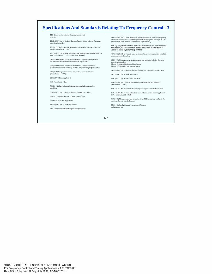
“QUARTZ CRYSTAL RESONATORS AND OSCILLATORSFor Frequency Control and Timing Applications - A TUTORIAL”Rev. 8.5.1.2, by John R. Vig, July 2001, AD-M001251.
10-4
122: Quartz crystal units for frequency control andselection
122-2 (1983) Part 2: Guide to the use of quartz crystal units for frequency control and selection
122-2-1 (1991) Section One: Quartz crystal units for microprocessor clock supply (Amendment 1 - 1993)
122-3 (1977) Part 3: Standard outlines and pin connection (Amendment 2 -1991, Amendment 3 - 1992, Amendment 4 - 1993)
283 (1986) Methods for the measurement of frequency and equivalent resistance of unwanted resonances of filter crystal units
302 (1969) Standard definitions and methods of measurement for piezoelectric vibrators operating over the frequency range up to 30 MHz
314 (1970) Temperature control devices for quartz crystal units (Amendment 1 - 1979)
314A (1971) First supplement
368: Piezoelectric Filters
368-l (1992) Part 1: General information, standard values and test conditions
368-2 (1973) Part 2: Guide to the use of piezoelectric filters
368-2-1 (1988) Section One - Quartz crystal filters
368B (1975) Second supplement
368-3 (1991) Part 3: Standard Outlines
444: Measurement of quartz crystal unit parameters
444-1 (1986) Part 1: Basic method for the measurement of resonance frequency and resonance resistance of quartz crystal units by zero phase technique in a π -network with compensation of the parallel capacitance Co
444444--4 (1988) Part 4: Method for the measurement of the load resonan4 (1988) Part 4: Method for the measurement of the load resonance ce frequency frequency ffLL, load resonance R, load resonance RLL and the calculation of other derived and the calculation of other derived values of quartz crystal units up 30 MHz values of quartz crystal units up 30 MHz
483 (1976) Guide to dynamic measurements of piezoelectric ceramics with high electromechanical coupling
642 (1979) Piezoelectric ceramic resonators and resonator units for frequency control and selection. Chapter I: Standard Values and ConditionsChapter II: Measuring and test conditions
642-2 (1994) Part 2: Guide to the use of piezoelectric ceramic resonator units
642-3 (1992) Part 3: Standard outlines
679: Quartz Crystal Controlled Oscillators
679-1 (1980) Part 1: General information, test conditions and methods (Amendment 1 - 1985)
679-2 (1981) Part 2: Guide to the use of quartz crystal controlled oscillators
679-3 (1989) Part 3: Standard outlines and lead connections (First supplement -1991) (Amendment 1 - 1994)
689 (1980) Measurements and test methods for 32 kHz quartz crystal units for wrist watches and standard values
758 (1993) Synthetic quartz crystal; specificationsand guide for use
Specifications And Standards Relating To Frequency Control - 3
-
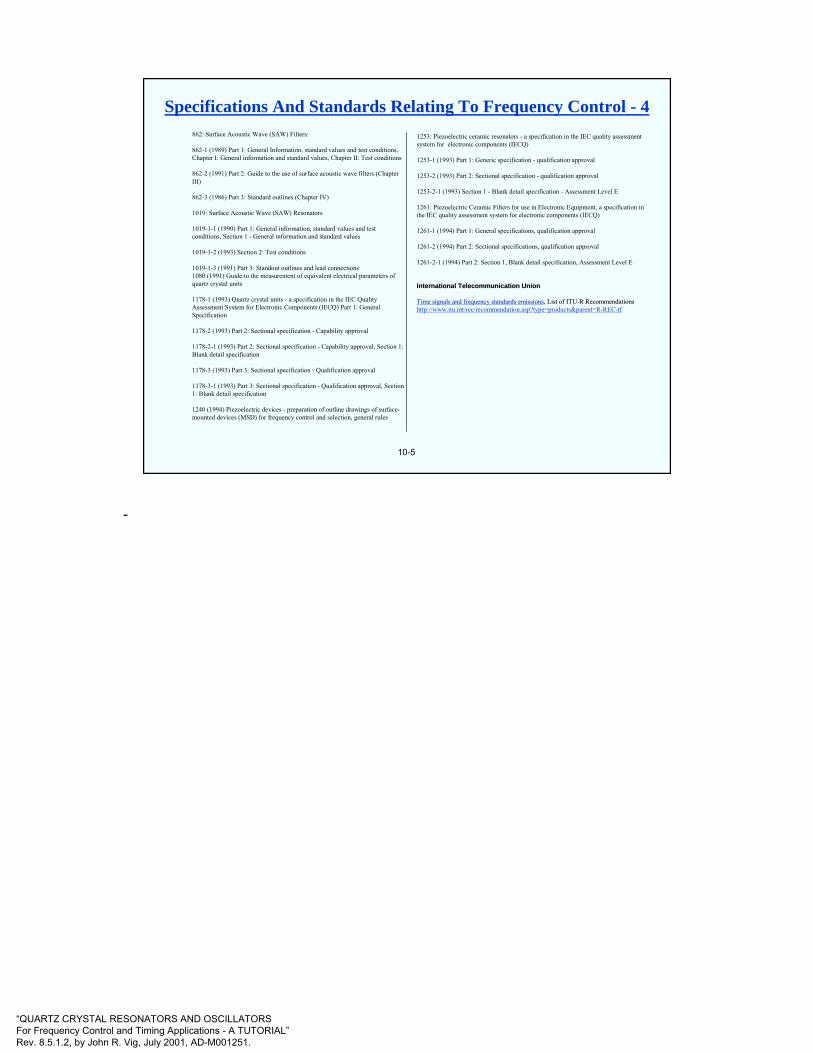
“QUARTZ CRYSTAL RESONATORS AND OSCILLATORSFor Frequency Control and Timing Applications - A TUTORIAL”Rev. 8.5.1.2, by John R. Vig, July 2001, AD-M001251.
10-5
862: Surface Acoustic Wave (SAW) Filters:
862-1 (1989) Part 1: General Information, standard values and test conditions, Chapter I: General information and standard values, Chapter II: Test conditions
862-2 (1991) Part 2: Guide to the use of surface acoustic wave filters (Chapter III)
862-3 (1986) Part 3: Standard outlines (Chapter IV)
1019: Surface Acoustic Wave (SAW) Resonators
1019-1-1 (1990) Part 1: General information, standard values and test conditions, Section 1 - General information and standard values
1019-1-2 (1993) Section 2: Test conditions
1019-1-3 (1991) Part 3: Standout outlines and lead connections1080 (1991) Guide to the measurement of equivalent electrical parameters of quartz crystal units
1178-1 (1993) Quartz crystal units - a specification in the IEC Quality Assessment System for Electronic Components (IECQ) Part 1: General Specification
1178-2 (1993) Part 2: Sectional specification - Capability approval
1178-2-1 (1993) Part 2: Sectional specification - Capability approval, Section 1: Blank detail specification
1178-3 (1993) Part 3: Sectional specification - Qualification approval
1178-3-1 (1993) Part 3: Sectional specification - Qualification approval, Section 1: Blank detail specification
1240 (1994) Piezoelectric devices - preparation of outline drawings of surface-mounted devices (MSD) for frequency control and selection, general rules
1253: Piezoelectric ceramic resonators - a specification in the IEC quality assessment system for electronic components (IECQ)
1253-1 (1993) Part 1: Generic specification - qualification approval
1253-2 (1993) Part 2: Sectional specification - qualification approval
1253-2-1 (1993) Section 1 - Blank detail specification - Assessment Level E
1261: Piezoelectric Ceramic Filters for use in Electronic Equipment, a specification in the IEC quality assessment system for electronic components (IECQ)
1261-1 (1994) Part 1: General specifications, qualification approval
1261-2 (1994) Part 2: Sectional specifications, qualification approval
1261-2-1 (1994) Part 2: Section 1, Blank detail specification, Assessment Level E
International Telecommunication UnionInternational Telecommunication Union
Time signals and frequency standards emissionsTime signals and frequency standards emissions, List of ITU, List of ITU--R RecommendationsR Recommendationshttp://www.itu.int/rec/recommendation.asp?type=products&parent=R-REC-tf
Specifications And Standards Relating To Frequency Control - 4
-
“QUARTZ CRYSTAL RESONATORS AND OSCILLATORSFor Frequency Control and Timing Applications - A TUTORIAL”Rev. 8.5.1.2, by John R. Vig, July 2001, AD-M001251.
10-6
A huge amount of frequency control information can be found at
http://www.ieee-uffc.org/fc
Available at this site are >100K pages of information, including the full text of all the papers ever published in the Proceedings of the Frequency Control Symposium, i.e., since 1956, reference and tutorial information, nine complete books, historical information, and links to other web sites, including a directory of company web sites.
Frequency Control Website
Some of the information at this website is available only to IEEE UFFC Society members.
-