slide 1 cocomo 2004 – peter hantos dr. peter hantos the aerospace corporation anchoring concurrent...
Post on 19-Dec-2015
219 views
TRANSCRIPT
Slide 1COCOMO 2004 – Peter Hantos
Dr. Peter Hantos
The Aerospace Corporation
Anchoring Concurrent Engineering Processes
19th International Forum on COCOMO and Software Cost Modeling, October 26-29, 2004, Los Angeles, California
2004. The Aerospace Corporation. All Rights Reserved.

Slide 2COCOMO 2004 – Peter Hantos
Acknowledgements
• This work would not have been possible without assistance from the following:– Reviewers
• Richard J. Adams, Software Acquisition and Process Office• Lance A. Diernback, Software Architecture and Engineering• Suellen Eslinger, Software Acquisition and Process Office
– Sponsor
• Michael Zambrana, USAF Space and Missile Systems Center,
Directorate of Systems Engineering– Funding source
• Mission-Oriented Investigation and Experimentation (MOIE)
Research Program (Software Acquisition Task)– Inspiration
• Dr. Barry Boehm, University of Southern California

Slide 3COCOMO 2004 – Peter Hantos
Agenda
• Introduction
• The Traditional Perspective on Life Cycles
• Anchor Points
• Generalization of Anchor Points
• Generalized Life Cycle Model
• Anchoring ASIC and PCB Processes
• Modeling a Platform-based Product Line Development Process
• Modeling Iteration on the Phase Level
• Conclusions

Slide 4COCOMO 2004 – Peter Hantos
Introduction
• The Usual HW/SW Dialog– Traditional SW Position:
• Give me the working hardware, and leave me alone– Traditional HW Position:
• Here are the specs, see you at final integration. Now leave me alone!– What Really Takes Place:
• HW is changing frequently during design. SW people are frustrated and inefficient. SW always ends up being the bottleneck
• Challenges, Challenges …– The Project Manager’s Challenge:
• Managing (estimating, planning, monitoring, and controlling) concurrent engineering processes
– The Process Architect’s Challenge:• Dealing with life cycle modeling complexity
- concurrent engineering of hardware and software- iterative/incremental processes
• We need to determine the optimal number of interactions and their optimal place in the life cycle

Slide 5COCOMO 2004 – Peter Hantos
The Traditional* Perspective on Life Cycles
HW/SW Integration and TestingSystem Qualification Testing
Operations and MaintenanceRe-validation/Re-verification
System Requirements DefinitionSystem Design
Software Requirements Def.
High-level Design (Architecture)
Detailed Design
Implementation (Coding)Unit Testing
Software IntegrationSoftware Qual. Testing
Hardware Requirements Def.
Preliminary Design
Detailed Design
FabricationTest
Hardware IntegrationHardware Qual. Testing
“Big Bang”
_____________________________*Chart is based on various software life cycle standards, e.g.:J-STD-016-1995, Annex B, Figure 4,5, and 6 IEEE/EIA 12207.0-1997, Annex I, Figure I.3

Slide 6COCOMO 2004 – Peter Hantos
What is Wrong With This Picture?
• Waterfall development of hardware and software
• “Big-bang” Integration and System Test
• Hardware-software units are developed in isolation
• Design trade-offs are expected on system level only
• Mitigation of hardware and software risks is separated; no opportunity for joint risk mitigation
• All software units are expected to be developed simultaneously
• Simplified, static view of architecture
• Static view of software assuming unchanging software entities across the life cycle
HW/SW Integration and TestingSystem Qualification Testing
Operations and MaintenanceRe-validation/Re-verification
System Requirements DefinitionSystem Design
Software Requirements Def.
High-level Design(Architecture)
Detailed Design
Implementation (Coding)Unit Testing
Software IntegrationSoftware Qual. Testing
Hardware Requirements Def.
Preliminary Design
Detailed Design
FabricationTest
Hardware IntegrationHardware Qual. Testing
“Big Bang”

Slide 7COCOMO 2004 – Peter Hantos
Anchor Points
• Anchor Points– Anchor points are a set of project planning milestones with specific objectives– Boehm’s original anchor points [Boehm96]:
• LCO (Life Cycle Objectives)• LCA (Life Cycle Architecture)• IOC (Initial Operational Capability)
– The need for these anchor points was determined on the basis of studying successful projects
• Representative Applications of Anchor Points– System/System of Systems Context
• DARPA-STARS (Defense Advanced Research Project Agency-Software Technology for Adaptable, Reliable Systems) [Boehm96]
• US Army FCS (Future Combat Systems) [Boehm04]– Project/Increment Context
• RUP® (IBM/Rational Unified Process) [Royce98]• MBASE - Model-Based (System) Architecting and Software Engineering
[CSE03]

Slide 8COCOMO 2004 – Peter Hantos
Generalizing Anchor Points for Concurrent Engineering
• Generalization Objectives– Improve estimation accuracy and control confidence – Extend the anchor point concept to inter-increment contexts to model
the concurrent development of increments– Extend the anchor point concept beyond software development
• Specific Goals– Extend the concept to cover the complete (“cradle to grave”) life cycle of
development increments– Apply the concepts to electronic hardware design, specifically to
• ASICs – Application Specific Integrated Circuits, and • PCBs – Printed Circuit Boards.

Slide 9COCOMO 2004 – Peter Hantos
Generalization Approach
• Key Elements of the Original Anchor Points – Stakeholder concurrence on the system’s life cycle objectives– Determination and validation of the system’s life cycle architecture
• Generalization Assumptions– The original definitions above are extendable and scalable– The generalized “increment” is a delivery, and not a development concept;
hence the new model will not explicitly reflect the development details– Properly defined and positioned anchor points represent stability in key
dimensions of the development process• Anchor point objectives might be achieved iteratively, but planned iteration loops do
not cross life cycle phase boundaries
• Generalization Approach– Interpret “stakeholder”, “system”, “architecture” in the extended contexts– Determine new anchor points and their objectives that are consistent with the
generalized interpretations– Use anchor points to connect and synchronize concurrent process streams

Slide 10COCOMO 2004 – Peter Hantos
Generalized Life Cycle Model
Phase1
LCO
Phase2
LCA
Phase3
IOC
Phase4
DER
Phase5
EOM
Phase6
Increment
• Phases are intentionally not named only numbered– Phase content stays flexible; phase activities are not pre-determined– Focus is on achieving anchor point objectives– Want to avoid confusion with RUP or MBASE
• New Anchor Points to be introduced– DER - Delivery Readiness – EOM - End Of Maintenance

Slide 11COCOMO 2004 – Peter Hantos
Stakeholder Commitment Modeling
Phase i
APx
Phase i+1P n-1 Trailing Process
Phase j
APY
Phase j+1P n Process in Question
Phase k
APZ
Phase k+1P n+1 Leading Process
• A generalization of the original “Stakeholders concur on the system’s life cycle objectives” key element to concurrent processes
• Stakeholder concurrence expressed as commitments:
– Upstream: Pn knows Pn+1’s objectives at APz and supports it with its delivery
– Downstream: Pn relies on Pn-1’s delivery to satisfy APY objectives

Slide 12COCOMO 2004 – Peter Hantos
Generalizing the Architecture Concept
• Architecture*– “Fundamental organization of a system embodied in its components,
their relationship to each other, and to the environment, and the principles guiding its design and evolution.”
• For Generalization, replace – “System” with “Increment”
– “Environment” with “Concurrently Developed Increments”
• Understand that the scope of “design” and “evolution” refers to all concurrent development streams and not only one
– Concurrently Developed Increments can be software or hardware
_________________* Definition from IEEE STD 1471-2000, IEEE Recommended Practice for Architectural Description of Software-Intensive Systems [IEEE00]

Slide 13COCOMO 2004 – Peter Hantos
Front-End Anchor Points – Focused Objectives
• LCO – Life Cycle Objectives– Product-related
• Definition of operational concept, scope, and top-level requirements• Architectural and design options
– Process-related• Life Cycle Plan defined
- Global plans for the whole life cycle, plus - Detailed plan for achieving LCA
• LCA – Life Cycle Architecture– Product-related
• Refinement of operational concept, scope, and top-level requirements• Resolution of LCO option-explorations, commitment to a feasible
architecture and technology solutions– Process-related
• Life Cycle Plan refined- Global plans for the rest of the life cycle, plus - Detailed plan for achieving IOC
Slide 14COCOMO 2004 – Peter Hantos
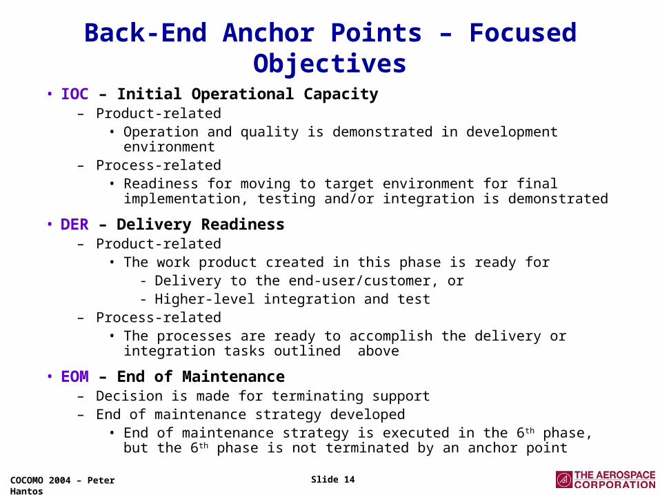
Back-End Anchor Points – Focused Objectives
• IOC – Initial Operational Capacity– Product-related
• Operation and quality is demonstrated in development environment– Process-related
• Readiness for moving to target environment for final implementation, testing and/or integration is demonstrated
• DER – Delivery Readiness– Product-related
• The work product created in this phase is ready for- Delivery to the end-user/customer, or - Higher-level integration and test
– Process-related• The processes are ready to accomplish the delivery or integration tasks
outlined above
• EOM – End of Maintenance– Decision is made for terminating support– End of maintenance strategy developed
• End of maintenance strategy is executed in the 6th phase, but the 6th phase is not terminated by an anchor point
Slide 15COCOMO 2004 – Peter Hantos
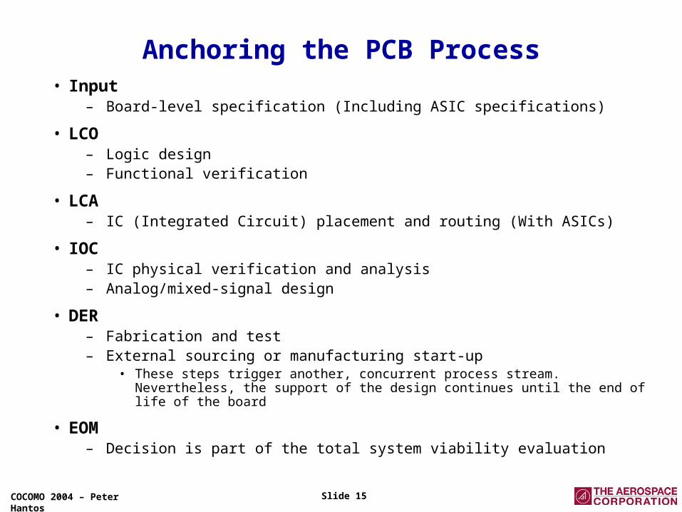
Anchoring the PCB Process• Input
– Board-level specification (Including ASIC specifications)
• LCO– Logic design– Functional verification
• LCA– IC (Integrated Circuit) placement and routing (With ASICs)
• IOC– IC physical verification and analysis – Analog/mixed-signal design
• DER– Fabrication and test– External sourcing or manufacturing start-up
• These steps trigger another, concurrent process stream. Nevertheless, the support of the design continues until the end of life of the board
• EOM– Decision is part of the total system viability evaluation

Slide 16COCOMO 2004 – Peter Hantos
Anchoring the ASIC Process
• Input – ASIC specification
• LCO– Virtual prototyping– ASIC system simulation– Behavioral modeling
• LCA– HDL (High Definition Language) design capture and simulation
• IOC– Rapid prototyping or hardware emulation– System verification
• DER– Fabrication and test– External sourcing or manufacturing start-up
• These steps trigger another, concurrent process stream. Nevertheless, the support of the design continues until the end of life of the ASIC
• EOM– Decision is part of the total system viability evaluation

Slide 17COCOMO 2004 – Peter Hantos
• Scenario A– ASIC and PCB specifications are the results of the sub-assembly design process– ASIC DER is synchronized with PCB LCO
• Actual ASIC is needed to carry out IC placement and routing (PCB LCA objective)
– EOM decision might trigger EOM for PCB and ASIC, but• ASIC must be supported until PCB’s end of life• PCB must be supported until Sub-assembly’s end of life
– Note that PCB design is highly constrained by the ASIC design process • Bulk of the work cannot proceed until ASIC is available• Plan poses increased schedule pressure on ASIC designers as well
ASIC-PCB Anchoring Examples-1
Sub-assembly
PCB
ASIC
LCO LCA
IOC DER
EOM
LCO
LCO LCA
LCA IOC EOM
EOM

Slide 18COCOMO 2004 – Peter Hantos
ASIC-PCB Anchoring Examples - 2
Sub-assembly
PCB
LCO LCA
LCO
ASIC
IOC DERLCO LCA
LCA IOC
EOM
EOM
EOM
• Scenario B– ASIC specification is technology-driven and known in advance
• ASIC design can start even before sub-assembly design start
– ASIC DER is synchronized with the beginning of PCB design• ASIC specifications and actual ASIC can be provided to PCB designers even before LCO even though it is only needed at LCO to
accomplish LCA objectives
– ASIC EOM decision will trigger an EOM for PCB, but not necessarily for the sub-assembly• For example, ASIC is redesigned for improved performance; as a result, PCB needs to be redesigned as well, but its external
electrical, electronic, and physical characteristics don’t change.
– Note that neither process is overly constrained by the other

Slide 19COCOMO 2004 – Peter Hantos
• Development of Product1
– Platform (HW, SW, or Software-Intensive System) is concurrently developed with Product1
– Platform architecture has to be finalized and provided when product planning starts– Platform DER is synchronized with Product1 LCA
• Platform has to be available to accomplish Product1 IOC• Or, in a more aggressive plan, Platform IOC would be synchronized with Product1 LCA
• Development of Product2 – Platform architecture information is provided when product planning starts
– A second Platform DER is synchronized with Product2 LCO or LCA
• Actual platform is provided to the design team as soon as possible, to complete Product2 IOC
– The last product’s EOM triggers EOM for the platform as well• Caveat: Platform technology obsolesce can also trigger EOM for the product(s)
Modeling a Platform-Based Product-Line
PlatformIOCLCO LCA EOM
DER
Product1
LCO LCA IOC EOM
DER
DER
Product2
LCO LCA IOC EOM
DER DER…

Slide 20COCOMO 2004 – Peter Hantos
Modeling Iteration on the Phase Level
• What is Iteration?– Iteration is the repeated execution of steps inside of the phase– Iteration is a risk-mitigation strategy to deal with complexity challenges– Planned iteration cycles (vs. “doodling” or “code-and-fix”) are driven by engineering objectives– Final number of iterations and their duration are not deterministic entities– The use of CCPM*-type buffers is suggested to model iteration planning uncertainties
• PAP (Post-Anchor Point) Buffer– The use of this additional buffer is suggested to model follow-up, post-anchor point activities– Note that PAP activities are concurrent with the activities of the next phase and they are not on the critical path; hence the distinction from CCPM buffers.
_________________* CCPM - Critical Chain Project Management [Gold97] is a buffering system originally introduced for the planning and control of the critical path in project networks.

Slide 21COCOMO 2004 – Peter Hantos
Conclusions
• A generalized life cycle modeling approach has been presented– The approach facilitates reasoning about concurrent engineering
process streams during planning and estimation.
• The models are – discipline-independent, but facilitate trade-offs across technical
disciplines,
– Intuitive, and easily translatable to Gantt charts for operational planning and control purposes.

Slide 22COCOMO 2004 – Peter Hantos
AcronymsAP Anchor Point ASIC Application Specific Integrated Circuit CCPM Critical Chain Project Management DARPA Defense Advanced Research Project Agency DER Delivery Readiness EOM End Of Maintenance FCS Future Combat Systems HW Hardware IC Integrated Circuit IOC Initial Operational Capability LCA Life Cycle Architecture LCO Life Cycle Objectives MBASE Model-Based (System) Architecting and Software Engineering PAB Post Anchor Point Buffer PCB Printed Circuit Board RUP IBM/Rational Unified Process SEI Software Engineering Institute SIS Software-Intensive System STARS Software Technology for Adaptable, Reliable Systems SW Software USC University of Southern California

Slide 23COCOMO 2004 – Peter Hantos
References[Boehm04] Boehm, B., et al., Spiral Acquisition of Software-Intensive Systems of Systems, Crosstalk,
May 2004 [Boehm96] Boehm, B., Anchoring the Software Process, IEEE Software, July 1996
[CSE03] Guidelines for Model-Based (System) Architecting and Software Engineering (MBASE),
v.2.4.0, USC Center for Software Engineering, February 11, 2003 [EETA04] Goering, R., Is verification really 70 percent?, Electronic Engineering Times – Asia,
August 2, 2004 [Gold97] Goldratt, E.H., Critical Chain, North River Press, Great Barrington, MA, 1997
[Hant00] Hantos, P., From Spiral to Anchored Processes: A Wild Ride in Lifecycle Architecting,
Proceedings, USC-SEI Spiral Experience Workshop, Los Angeles, CA, February 2000 [IEEE00] IEEE STD 1471-2000, IEEE Recommended Practice for Architectural
Description of Software-Intensive Systems, 2000 [IEEE97] IEEE/EIA 12207.0-1997, Standard for Information Technology Software Life Cycle
Processes – Implementation Considerations [JSTD95] J-STD-016-1995, (Interim) Standard for Information Technology Software Life Cycle
Processes Software Development Acquirer-Supplier Agreement, September 1995 [Royce98] Royce, W., Software Project Management – A Unified Framework, Addison-Wesley, 1998
[Smith97] Smith, M.J.S., Application-Specific Integrated Circuits, Addison-Wesley, 1997

Slide 24COCOMO 2004 – Peter Hantos
Backup

Slide 25COCOMO 2004 – Peter Hantos
Anchoring Basic Software Development Patterns
Waterfall Development Iterative Development
Translation-based Development