slide 1 intro to marine finite element analysis paul h. miller, d.eng. pe united states naval...
Post on 20-Dec-2015
215 views
TRANSCRIPT

Slide 1
Intro to Marine Finite Element Analysis
Paul H. Miller, D.Eng. PE
United States Naval Academy

Slide 2
Presentation Overview• What is FEA and what will it do
for us • What FEA will not do for us• Limitations of FEA• Case Studies

Slide 3
Getting started with a simple exampleA new mast step for an old wooden sailboat
t=0.5”
• Designer: L. Francis Herreshoff, 1955
• Built: 1962 Lunenberg, N.S.
• Original Mast Step was Red Oak (not designed that way)
• It broke at a bad moment!

Slide 4
The Mast StepAs it’s thickness is about the same dimension
as its width, we must use solid elements.
• Loads – 7000 lb down
• Geometry – 24”x4”x4”
• Material – Black Locust
• Boundry Conditions – supported by 3 oak floors
The grain is longitudinal

Slide 5
t=0.5”
• The actual boundary conditions with the three floors.
Black Locust mast step
White Oak floors
Floor grain is vertical Forward

Slide 6
Deformation (300x)

Slide 7
Displacement
Maximum displacement is 0.0084”

Slide 8
Stress with vertical grain floors
Max Stress = -1889 psi

Slide 9
Stress with transverse grain floors
Max Stress = -2706 psi43% higher!
But floor loads are more even

Slide 10
Rolling Shear Stress
Maximum shear stress is 559 psi

Slide 11
Mast Step Analysis Results• The analysis took 5 hours• The predicted weight was 7.5 pounds• The minimum factor of safety for
bending was 10.2• The minimum factor of safety for
shear was 4.4• The recommended minimum FOS is 4• Therefore LFH over-designed it by
3/8”!• I built it to LFH’s drawing…

Slide 12
What is Finite Element Analysis?In the real world of structural response…
• Deform – strain (in/in)– If the strains are always
proportional to the load it is “linear deformation”
– If not, then “non-linear”
• Have internal stress (psi)• Are made of materials
– Which could be linear or non-linear themselves
• Discrete Forces• Pressures• Vibrations (or
fatigue)• Accelerations
– Gravity– Dynamics
• Temperature• Moisture
Objects with loads on them: Loads include:

Slide 13
In the world of mathematics…• FEA divides the object up into multiple
small parts (up to 100K+!)• Each part is represented by stiffness
constants (like springs, f=k·x)• All the parts are combined
mathematically (by matrix algebra) into a global structure
• The solution is found from equilibrium (ΣF=0, ΣM=0)
FUK Stiffness matrix
Displacements and Rotations (DOFs)
Loads

Slide 14
Solving the basic equation for the unknown degrees of freedom…
1. Finding the final displacement gives us the elongation
2. Elongation gives us the strain3. Strain and area gives us the stress4. Stress and failure criteria give us
the Factors of Safety!
KFU 11

Slide 15
Physical modeling of structures
• An FEA model is made of simple structural “elements” connected at “nodes”
• The basic building blocks (elements) are:– Beams (1 primary dimension)– Plates/shells (2 primary dimensions)– Solids (3 primary dimensions)
“Primary” means “much bigger than the other dimensions”

Slide 16
Just To Avoid Confusion!An element with 2 Primary Dimensions, a shell element, has a length and a width, but is thin compared to the other two dimensions.
It can be either used in either 2-D analysis (x and y axes) or in 3-D analysis (x, y and z axes).

Slide 17
Common Structural Element Types
• Solid• Shell• Beam• Cable• Truss• Radiation
• Mass• Gap• Immersed
pipe• Buoy• Magnetic• Fluid/heat

Slide 18
FEA can handle almost any structure
• It’s greatest power (and cost) is with complex structures.
• The structure needs to be envisioned in terms of element types which are available, and suitable.
• The structure is then represented with many (often thousands) of these elements.

Slide 19
Example of Beam/Cable/Truss Elements:What they are
•
•
2 nodes,Each node has up to 6 degrees of freedom, giving 12 per element

Slide 20
Example of Beam Elements: A Mast tube is shells, spreaders are beams, rigging is cables

Slide 21
Example of Shell Elements: What they are
4 nodes,Each node has up to 6 degrees of freedom, giving 24 DOF per element

Slide 22
Example of Shell Elements: A 77-foot Hull
Note the beam elements

Slide 23
Example of Solid Elements: What they are
8 nodes,Each node has up to 3 degrees of freedom(translation only), giving 24 DOF
Slide 24
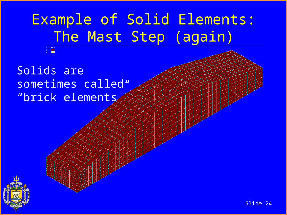
Example of Solid Elements:The Mast Step (again)
Solids are sometimes called “brick elements”

Slide 25
What FEA does beautifully!
• Handles complex geometry. (Indeterminate structures)
• Isotropic materials (materials with consistent properties in all directions)
• Static and simple dynamic problems• Examples
– A steel keel, a bronze rudder shaft– Metal hulls (tanker fatigue)
• Accuracy is within 0-5%!

Slide 26
What FEA does “OK”…
• Complex materials– Composites– Wood
• Non-linear static deformation (x5)
• Buckling of isotropic materials (x2)
• Increased uncertainty– From 1-5%
potential error– To 3-30% error– HIGHER MIN
FOS!
• Increased manhours required to prepare model
This means: Examples:
Slide 27
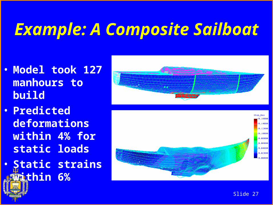
Example: A Composite Sailboat
• Model took 127 manhours to build
• Predicted deformations within 4% for static loads
• Static strains within 6%

Slide 28
Composite Sailboat• Fatigue-influenced dynamic strains were
predicted within 14% when compared to strain gages and coupons.

Slide 29
Non-linear deformationHigh Aspect Ratio Rudder
• 8 foot span/16 lb• 20” of tip
deflection• High membrane
stresses reduce predicted deflection and stress
• 5% error in deflection

Slide 30
Tsai- Wu Factors of Safety

Slide 31
Non-linear Mast Deformation
• Small dinghy mast
• Used to size spreaders, wire and pretension
• Input was gust spectrum
• 8% error in deformation

Slide 32
What FEA does not do well
• Dynamic impact (slamming loads)• Joints ( composites or metal )• Buckling of “real world”
composites.• Misc details unaccounted for in
element formulations.• Error can be 30-300%!

Slide 33
Dynamic Analysis• FEA has great strengths in dynamic
analysis for certain types of problems.
• Standard FEA doesn’t handle slamming impacts well.
• One of the major difficulties are in the definition of the loads.
• The other is in the speed of the transient nature of the load.

Slide 34
Joint Analysis with FEA
• FEA is good for extracting loads at joints.
• FEA is weak in micro analyzing joint designs
• This is primarily due to difficulty with material properties and failure mechanisms.

Slide 35
Joint Design with FEA(some variation with programs)
1. Normal FEA solution assumes joint is perfect2. Either a) list nodal forces
b) use nodal stresses and area3. Determine stress concentration factors for
specific joint geometry4. Calculate joint loads by spreadsheet (isotropic
or wood) or5. Use laminate analysis program and
spreadsheet (for composites)

Slide 36
Not all aspects of structres can be accounted for in FEA models

Slide 37
Failure mode prediction is only as good as it’s modeling.
This means realistic material testing to support the FEA.
“Special” failure mode analysis (post-processing) using spreadsheets or macros
Slide 38
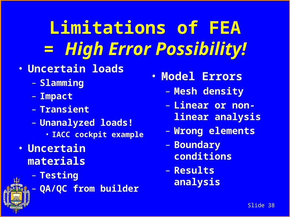
Limitations of FEA= High Error Possibility!
• Uncertain loads– Slamming– Impact– Transient– Unanalyzed loads!
• IACC cockpit example
• Uncertain materials– Testing– QA/QC from builder
• Model Errors– Mesh density– Linear or non-
linear analysis– Wrong elements– Boundary
conditions– Results analysis

Slide 39
A Multiple Issue Problem!• Loads, materials and boundary conditions• FEA assumes “continuum mechanics”
Eventually we got the deflections to match within 10%,But the strength was under predicted by 110%.

Slide 40
Another Case Study
• A 77-foot performance cruiser
• Designed by Carl Schumacher

Slide 41
Project Overview
• Began in September 1998• Structures to meet ABS and
realistic loads if not specified• Multiple materials intended• Goal is “ULDB” cruiser
– Light but strong with a deep bulb keel

Slide 42
FEA work• Designer subcontracted out structural
FEA design• Designer provided dxf files for all
geometries (hull, appendages)• FEA consultants optimized and
specified construction• Designer did hull structure drawings• Consultants did keel structure drawings
and interfaced with keel and hull manufacturer to ease construction

Slide 43
Design Limit Load Cases
• Upwind in heavy air, wave height equal to freeboard, wave length equal to boat length
• Slamming• Grounding• Lifting
Each load case drove the design of different parts of the boat.

Slide 44
Upwind in 30 knots on port tack
Rig loads supplied by mast maker

Slide 45
Displacements (25x)
Maximum displacement = 3.32”Max rotation 0.5 degrees
Slide 46
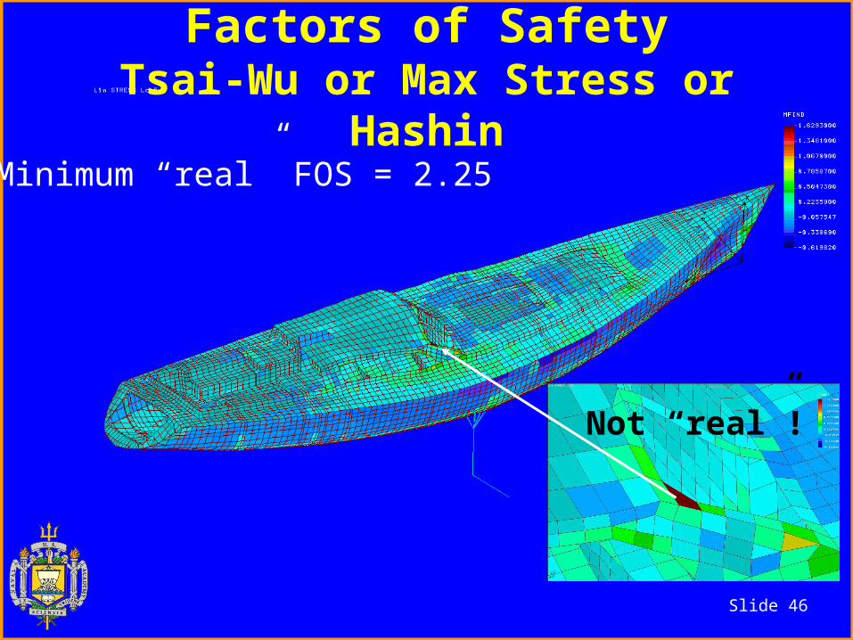
Factors of SafetyTsai-Wu or Max Stress or Hashin
Minimum “real” FOS = 2.25
Not “real”!

Slide 47
Interior

Slide 48
Interior FOS

Slide 49
Project Summary (to date)
• Smooth transition of files (AutoCad, GenericCad, Excel, Word)
• Communication was 50% phone, 45% email, 5% meetings
• FEA was approximately 320 hours• A third of that was redesign due
to the owner’s wishes