slidedriver dc operators, which fully comply with ul 325 ... · by downloading and using this...
TRANSCRIPT

www.hysecurity.com D0778
SlideDriver DC
222 DC Relay manual
DISCLAIMER HySecurity relay-controlled hydraulic gate operators do not meet current UL 325 Safety Standards and that HySecurity recommends decommission and replacement of all manufacturers’ relay-controlled operators with modern Smart Touch™ based operators, which fully comply with UL 325 safety standards. By downloading and using this document you acknowledge that HySecurity no longer provides parts or technical support for those older operators.
Note HySecurity accepts no responsibility, implied or express, for claims arising from continued use of pre-2001 relay-controlled operators.

222 DS, 222 DX, 222 DE, SLIDE GATE OPERATORHANDBOOK
SS28
Manufacturers and Designers of Hydraulic Systems
Hy-Security Gate Operators

Cautionary Notes also see illustration on next page:
• Hy-Security gate operators are designed for vehicular traffic; not pedestrians. Directall pedestrian traffic to a separate walk-through gate, and clearly display the warningsigns on both sides of the vehicle gate.
• Verify that the gate operator is marked as appropriate for the type and usage class ofthe gate. External sensors must be installed to protect against accidental entrapment inboth the opening and closing directions of gate travel.
• This type of gate operator must not be installed on the public, or non-secured side ofthe gate. To minimize the risk of entrapment, assure that the installation includessufficient clearance between the gate and adjacent structures.
• Children must never be allowed to play on or around the gate.• All access controls must be mounted at least six feet away from the gate and have a
security feature to prevent unauthorized use.• Install entrapment protection devices and sensors devices appropriate for the type of
gate and usage class application: cover exposed rollers, screen across the face of thegate, install electric edge sensors, photoelectric sensors, guard posts, and moving gatealarms. Test all of your entrapment sensors to insure that they are working in theproper manner.
• Install physical stops for the gate panel, in each direction. This will assure that the gate does not accidentally travel farther than intended.• Always make certain the operator is properly electrically grounded.• Construct or screen automatic sliding gates, from the bottom of the gate to a minimum
height of four feet, so that a sphere 2 1/4" in diameter cannot pass through. The 2 1/4"restriction also applies to the portion of the adjacent fence that the gate covers whenopen.
• When constructing/installing sliding gates, always minimize the gap between gate andfence. The gate must move freely in both directions. Never over-tighten a clutch orrelief valve to compensate for a stiff gate.
Automatic gate operators provide convenience and security to users. However, because these machines canproduce high levels of force it is important that all gate operator system designers, installers and end users beaware of the potential hazards associated with improperly designed, installed or maintained systems. Keep inmind that the gate operator is only one component of the total gate operating system. It is the joint responsi-bility of the specifier, designer, purchaser, installer and end user to verify that the total system is safe for itsintended use. All parties should be aware that entrapment in a moving vehicle gate can cause serious injury ordeath.
Important Information
Page 1 of 2 7/27/00 S44a
Minimize
Gap
READ THIS FIRST!READ THIS FIRST!READ THIS FIRST!READ THIS FIRST!READ THIS FIRST!
CommonCommonCommonCommonCommonIndustryIndustryIndustryIndustryIndustrySymbolsSymbolsSymbolsSymbolsSymbols Attention
–Take Note––Danger–
Keep AwayPossible
Pinch PointEntrapment
Zone

Entrapment Protection DeviceEntrapment Protection DeviceEntrapment Protection DeviceEntrapment Protection DeviceEntrapment Protection Device Schematic for Sliding Gates Schematic for Sliding Gates Schematic for Sliding Gates Schematic for Sliding Gates Schematic for Sliding Gates
This schematic view is not meant to recommend the only way to set up your configurtion,but to point out the various elements of a proper automatic vehicular gate installation. Thegate operator itself is only one component in the total system. Always install a separatepedestrian gate.
Page 2 of 2 6/1/00 S44b
Photocells forboth directionseach side of gate
2¼" safety mesh preventsreach-through: height notless than 48 inches
Warning signsmust be on bothsides
Gate edgesensors
Gate edge sensor,on leading edgeand trailing edge
Physical travelstop, both ends
Photocells forboth directions
Physical travelstop, both ends
Stop and resetbutton
Audioalarm
Access controlsat least six feetaway from gateand operator
Guard posts
Keep this gap assmall as possible
Attention
NOTE: All wheels must be covered.(Wheels and covers not shown forclarity).
(By others)
(EACED 005 MK)
(By others)
(By others)
(aekph 001 thb)(eaced 005 mk)
(acal 001)
(By others)
(By others)
(aekph 001 thb)
Edge transmitter(ERCTR 020)

ëÉ~ííäÉI=ï~ëÜáåÖíçå
�����
eóÇê~ìäáÅ=päáÇÉ=������������
�������
�����������
����������������������
���
��������
��������
�������
����
����
����
������
��������
��������
��
� ��
����
���������
�����
d~íÉ=léÉê~íçê
Gate Panel
Concrete Slab
Power transmission: Hydraulic motors to drive rail
Drive Rail
Polyurethane drive rail wheel treadeliminates the high wear metal-to-metalcontact of conventional chain-drive systems.
9.75” Top of slab to topof drive rail.
14.5”
26”
26”
Safety Mesh
Roll Pins forperfect splices

Exploded Parts BreakoutParts, Part Numbers and KitsParts, Part Numbers and KitsParts, Part Numbers and KitsParts, Part Numbers and KitsParts, Part Numbers and Kits
Slide Gate Operator Exploded Parts Breakout
Hydraulic Motor W/FTGS (2)222 X1, 444 XS: HMOMO K24 WRS
All others: HMOMO K10 ERS
Motor Mount Pinand Retaining Bolt
MSLDU 012 SSK (2)
Motor Mount ArmUpper: MSLDU 042 TLower: MSLDU 042 B
Heater Location(Optional)
Limit Switch (2) 111LS: ESWLS 224 111All others: Left Side: ESWLS 224 SHRT Right Side: ESWLS 224 LONG
Drive Wheels222 EX, X1& 444 series: MSLDW 008 HY All others: MSLDW 006 HY
111 LS Idler WheelMSLDW 006 I
Wheel Clamping AssemblyMSLDU 070 CAST
10 Ga Steel Chassis
SolenoidValve
PressureGauge
"E" ManifoldHMAMA 222 BVK
Electric Motorwith Pump and
Reservoir
Pushbutton Station
On/OffSwitch
ElectricControlPanel
AWOG with Manifold
Power Units are Detailed byOperator Series on next two pages

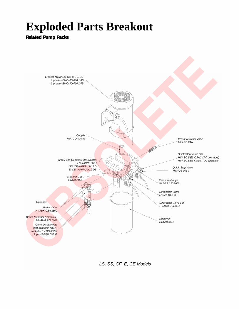
Exploded Parts BreakoutRelated Pump PacksRelated Pump PacksRelated Pump PacksRelated Pump PacksRelated Pump Packs
Quick Disconnectssocket--HSFQD 002 S
plug--HSFQD 002 P
Quick Disconnects for XS only: socket--HVAQD 004 S
plug--HVAQD 004 P
Brake Manifold (Complete)HMAMA 222 BVK
Brake ValveHVABK CBA 1500
Breather CapHRSBC 001
Pump Pack Complete(less motor)
HPPPU H13 S3E
Soft Start Manifold(Complete Kit)HMAAC 222 SSK
Pressure GaugeHASGA 120 MINI
Directional ValveHVADI DEL 2P
Directional Valve CoilHVASO DEL 024
ReservoirHRSRS 004
CouplerMPTCO 010 9T
Electric Motor EX, CX, X1, XS1 phase--EMOMO 010 2.0B3 phase--EMOMO 030 2.0B
XS: 3 phase only--EMOB6 236 5.0C
Quick Stop ValveHVAQS 001 C
AWOG HoseHMAAC 111 H
Quick Stop CoilHVASO DEL QSAC
EX, CX, X1, XS Models
Relief ValveHVARE LAN
Exploded Parts BreakoutRelated Pump PacksRelated Pump PacksRelated Pump PacksRelated Pump PacksRelated Pump Packs
Electric Motor LS, SS, CF, E, CE1 phase--EMOMO 010 1.0B3 phase--EMOMO 030 1.0B
CouplerMPTCO 010 9T
Pump Pack Complete (less motor)LS--HPPPU H11
SS, CF--HPPPU H12 DE, CE--HPPPU H12 DE
Breather CapHRSBC 001
Brake ValveHVABK CBA 1500
Brake Manifold (Complete)HMAMA 222 BVK
Quick Disconnects(not available on LS)
socket--HSFQD 002 Splug--HSFQD 002 P
Pressure GaugeHASGA 120 MINI
Directional ValveHVADI DEL 2P
Directional Valve CoilHVASO DEL 024
ReservoirHRSRS 004
Optional:
Pressure Relief ValveHVARE FAN
Quick Stop ValveHVAQS 001 C
Quick Stop Valve CoilHVASO DEL QSAC (AC operators)HVASO DEL QSDC (DC operators)
LS, SS, CF, E, CE Models


The on/off switch on the electric control panel of the drive unit does not disable all DC power to the operator,even if the AC power has been disabled at its source. The disconnect in the DC power supply enclosure mustbe actuated (either pull disconnect or switch depending upon operator type) to insure disconnect of all DCpower to the drive unit.
The disconnect in the power supply must be off if the AC source power is to be absent for more than oneweek. This avoids slowly discharging the batteries into the battery charger. Batteries will self discharge andtherefore the DC power supply must not be stored for a period longer than 6 months without recharging thebatteries.
Batteries contain sulfuric acid. If batteries are dropped or damaged, be cautious not to get acid in the eyes, onskin, or on clothing.
Be certain to observe polarity when connecting the batteries, or adding accessories. Reversed polarity mayresult in a non-functional operator or possibly damage a component. Red is (+) positive, and black is (-)negative. Black is common, terminal #10 is common, and all wires labelled number 10 in the operator arecommon.
Since the electrical current under load is very high, be certain that the minimum conductor size, specified inthe installation instructions, is used for the connection between the battery pack and the operator. If thebattery pack is more than 30 feet from the operator, use a larger wire size, according to the distance betweenthe operator and the batteries.
If shorted, batteries will generate a very high current. Observe special care when connecting the cables to thebatteries that the polarity is correct. The batteries are connected in a series circuit: join the positive (+)terminal from one battery to the negative (-) terminal of the next battery.
Since this operator is intended to run on batteries, control of the load is important. Easier moving gates willdrain less energy from the battery, preserving capacity for more cycles during a power failure.
Hy-Security Gate Operators uses a permanently sealed, gelled electrolyte type battery, which needs nomaintenance over its life span. A low voltage sensing relay protects the batteries from damage which could becaused by over discharge. The charger automatically regulates its output to allow high output when thebattery is partially discharged. The output will automatically be reduced to zero as the batteries become fullycharged.
Batteries have a finite life. As the batteries age they will lose some of their capacity to store energy. If thetotal amount of back up capacity is critical, plan to replace the batteries after 5 years of use. Properly disposeof or recycle used batteries.
Batteries are rated to perform to capacity at a temperature of 77 degrees farenheit. Below 77 degrees, the"amp hour" capacity is temporarily reduced. For example, at freezing, the capacity is 75%, at 10 degrees, thecapacity is 50%. Hy-Security Gate Operators insulate and heat the battery pack to guard against this loss. Donot remove any insulation or the performance of the system may be adversely affected.
Batteries can be damaged by excessive heat, which may shorten their life span. Therefore, do not paint thebattery enclosure a dark color that could cause it to absorb a lot of heat from sunlight.
IMPORTANT SPECIAL NOTES REGARDINGIMPORTANT SPECIAL NOTES REGARDINGIMPORTANT SPECIAL NOTES REGARDINGIMPORTANT SPECIAL NOTES REGARDINGIMPORTANT SPECIAL NOTES REGARDINGD.C. POWERED GATE OPERATORSD.C. POWERED GATE OPERATORSD.C. POWERED GATE OPERATORSD.C. POWERED GATE OPERATORSD.C. POWERED GATE OPERATORS
6/22/00 SS53a

Installation Instructions for DC Powered Sliding Gate OperatorsInstallation Instructions for DC Powered Sliding Gate OperatorsInstallation Instructions for DC Powered Sliding Gate OperatorsInstallation Instructions for DC Powered Sliding Gate OperatorsInstallation Instructions for DC Powered Sliding Gate Operators(Models 222 DS, DE, DX)(Models 222 DS, DE, DX)(Models 222 DS, DE, DX)(Models 222 DS, DE, DX)(Models 222 DS, DE, DX)
1. See drawings S13A & S13B for concrete slab size, operator footprint, and spacing dimensions. With the aid of the template enclosed inside the operator locate the operator with clearance of 1 3/4” to the gate panel. Mounting slots allow for fine adjustment.
2. Mount operator pad with a minimum of four concrete anchor bolts of ½” diameter.
3. Remove the plastic shipping plug on the pump manifold and replace it with the vented cap supplied. You will find it in the bag with the plastic limit ramps.
4. Mount the DC power package on support posts and channel strut as shown on drawings SS19 and SS20. The power supply should be kept near the drive unit because of the high motor current achieved by this system.
5. Injury and Entrapment Protection - Minimum Safeguards:A. Since automatic gates are not intended for pedestrian use, always install a separate pedestrian walkway and access gate. Install signs which direct persons to use the pedestrian gate, and not to enter through the vehicle gate.
B. Be certain that all open gate rollers are completely guarded by covers.
C. Be certain that the gate has been constructed such that the opportunity for persons to reach through any opening have been minimized. A sphere 2¼” must not pass through any part of the gate, or the fence adjacent to the gate when fully open. It may be necessary to install screening to prevent reach through injury.
D. Placement of physical stops for maximum open and maximum close is essential to prevent any over travel that might allow the gate to fall. The limit ramps are not to be used as gate stops.
E. Be certain that all operating switches are located at least a six foot distance from the gate, to reduce the possibility of any attempt to reach through in order to operate the gate.
F. Be certain to mount at least two of the enclosed 8½” x 11” warning placards on each side of the gate to warn users of the hazards of power operated gate.
G. Button Station Operation: Be certain to mount a warning placard near each button station that warns that the area must be clear before operating the gate. If there are no entrapment protection sensors to guard the open and close operation of the gate, the push button station must be wired for constant hold operation only. This is achieved by cutting jumper wires in the control circuit, see drawing E124T1.
H. Automatic Operation: Entrapment protection sensors must be installed to guard both the opening and closing of the gate. Install two photo electric eyes, or attatch a minimum of two edge sensors to create a reversing function for each direction of gate travel. All sensors guarding the closing
direction connect to terminals #1 and #6 in the control box. All sensors guarding the opening direction connect to terminals #9 and #6. See drawing #E41 for mounting and connection details of
the edge sensors. Caution: Vehicle detectors are not entrapment protection sensors.Page 1 of 4 7/19/00 SS21a

Installation Instruction Continued...Installation Instruction Continued...Installation Instruction Continued...Installation Instruction Continued...Installation Instruction Continued...
6. Connect 115 V, 208V, or 230V source power (according to the version ordered) to the DC power supply at the terminals marked for the AC line connection.
7. If the optional heater is ordered in the drive unit, connect AC supply wires from the 15 A fuse and AC terminal in the DC power supply to the loose (black and red) heater wires in the drive unit electrical enclosure.
8. Being careful to observe polarity, connect two separate 24V DC circuits from the DC power supply to the drive unit, one circuit for the controls and the second circuit carries the high current to the motor. Models DS and DE, require minimum 8 gauge wires to connect the power supply to the drive unit. Model DX, requires minimum 2 gauge wires from the power supply to the drive unit. Connect the red wire directly to the (+) terminal on the motor and connect the black wire to the bottom of the contactor mounted on the motor. All DC operators require separate 14 gauge wires minimum for the control circuit. Connect the 14 gauge wires to the loose wires at the back of the ON/OFF switch in the drive unit. (Left front corner of the control box.)
9. Test the basic functions of the operator first, before connecting any external control wiring. If your operator is equipped with vehicle detectors, be certain that they are connected to a loop or un-plugged so that they do not cause interference with the function of the machine. If the motor turns, but nothing moves, be certain that the hose quick connectors are firmly engaged. If the operator works, but open and close func- tions are reversed, refer to step 11.
10. All slide operators are manufactured to be right hand. If reversing the hand is necessary, simply unplug and reverse the limit wiring on the left side of the control enclosure. A label is affixed on the control panel which describes this procedure in more detail. It is also necessary to reverse the two hydraulic hoses going to the pump. All 222 models are provided with hydraulic quick connectors which require no tools to reverse handing. Run the operator to verify correct functioning. If the hydraulic hoses were incorrectly reversed, the gate will move in the opposite direction than command. If the limit switch cords were incor- rectly reversed, the operator would not stop when the gate reached its full travel. Never reverse wiring to the push button station.
11. After testing the basic functions, follow our electrical connection diagrams to add any accessories or external control wiring. Test the operator functions again.
12. Install drive rail on the gate panel at the specified height. The drive rail must be close to the center of the cutout in the operator housing as it passes between the drive wheels. Check to see that the arms supporting the wheels are similar angles from horizontal. Be sure that the drive rail maintains a consistent height in relation to the operator wheels, throughout the travel of the gate. (This may not be level or parallel with the gate frame because the gate panel and the fence may not be level) The maximum up and down variance of the drive rail, as it passes between the wheels, is one inch for the entire length of the gate travel. The point at which the rail should pass between the wheels is marked on the exterior of the operator housing.
13. Actuate the toggle clamp to grip the wheels onto the drive rail. Gauge the tension on the red spring. If more or less tension is needed, release the toggle clamp, adjust the nut on the threaded rod that penetrates the spring. A compression to 2” - 2 1/8” in height will be sufficient even for very heavy gates. Slightly less compression should be used for gates that weigh under 1000 pounds, or roll very easily.
Page 2 of 4 7/19/00 SS21b

14. Adjust the lever arms of limit switches to maintain at least ¼” clearance from the underside of the drive rail. This will avoid false tripping of the limits (see drawing S22). The limit switch arm should be approxi- mately in the center of the rail channel. If adjustment is required, remove the limit arm before bending. This will avoid breaking the head of the switch. Locate the plastic limit ramps in the underside of the drive rail to control maximum travel of the gate in the open and close direction. Mount the limit ramps to trip the limit switches three to six inches ahead of the desired gate stopping position. This clearance is needed for gate deceleration travel, after the limit switch has been tripped.
15. Check the “soft stop” open timer, which is mounted on top of the control relay. The label on the timer dial shows the minimum and maximum settings. In operation the timer only needs to be set long enough for the gate to coast to a smooth stop after opening. There is no bad effect if the timer is set for too long, except that the operator cannaot be started closed until this timer times out. There is no “soft stop” timer adjust- ment for the close direction.
16. Set the maximum run timer, which is located at the extreme right, inside of the electrical panel. The range is adjustable to 1 minute. Set the timer for twice the amount of the needed for the gate to traverse the opening.
17. DC powered operators include a special low voltage sensing relay (VSR) to protect the batteries from damage as a result of over discharge. The factory has preset the VSR relay to drop out 20.5 volts. The VSR relay will re-engage at 24 volts. The circuit design will always allow the gate to attain full travel before the low voltage relay can disable the gate. The VSR relay is factory wired for fail secure (closed) operation. If fail open is desired, the VSR relay must havce its normally open contact wired to terminals #3 and #5. Be certain to remove jumper from terminal #3 to #5 and jumper #1 to #1A.
Adjustment of accessories and information about two foot/second operatorsAdjustment of accessories and information about two foot/second operatorsAdjustment of accessories and information about two foot/second operatorsAdjustment of accessories and information about two foot/second operatorsAdjustment of accessories and information about two foot/second operators
1. Set “timer to close” accessory for desired delay. This option timer is located on the left side of the main control relays. The range is adjustable from 1 to 30 seconds. The timer willl close the gate from any position, but all open and safety signals must be absent.
2. Models 222 DE and DX, have a reverse delay timer mounted at near center of the control panel (to identify components, see drawing E124T1. The delay is adjustable from .3 to 3 seconds, and works together with the soft stop feature to provide smooth reversing. Larger gates will only need a second or less. The time needed to stop and reverse a gate is partly a function of the optional brake valves that are included with many models (to identify components, see drawing SS44. Review the following step, number three, for correct adjustment of the brake valves.
3. All two foot per second operators, as well as any operator that is intended to drive gates in excess of 1,000 pounds should be equipped with the “E” option which adds a reverse delay and hydraulic brake valves, to rapidly decelerate a gate. The positioning of the limit ramps should be 3 to 6 inches ahead of full gate travel to give some space for deceleration. Adjustment of the brake valves, one for each direction, affects the limit switch adjustment. If adjustment is necessary, loosen the 9/16” lock nut on the end of the brake valves (located on the front side of the hydraulic pump). Turn the adjustment stem with a screwdriver. The adjustment works over a range of four turns. Clockwise adjustment will stop the gat e more rapidly. If the adjustment is set to loose, the gate will coast too far, If the adjustment is set too tight the gate speed will decrease. Be certain to re-tighten the locking nut when the adjustment is complete.
Installation Instruction Continued...Installation Instruction Continued...Installation Instruction Continued...Installation Instruction Continued...Installation Instruction Continued...
Page 3 of 4 7/19/00 SS21c

Special information about two foot/second operatorsSpecial information about two foot/second operatorsSpecial information about two foot/second operatorsSpecial information about two foot/second operatorsSpecial information about two foot/second operators
To obtain the higher speed of the 222 DX, the pump flow rate and drive wheel size have been increased. Themotor horsepower is also doubled. Just like an automobile, a two foot/second operator must also incrporate ameans to allow for acceleration to ull speed, and to decelerate to a smooth stop. The gate is stopped by adjust-able hydraulic brake valves, which are included as standard equipment in this model. For smooth acceleration,the “DX” operator incorporates a device that eases the gate to full speed by dampening the initial hydraulicflow rate during start up. The following are the special instructions that apply only to our two foot/secondoperators.
1. Verify that the soft stop timer and reverse delay timer have been set for long enough time to allow the gate to come to a smooth stop after opening or when reversing. See step #16 in the installation instructions.
2. Be certain that the brake valve adjustments, described in the previous step #3 have been performed. Since the gate moves at twice the speed, the brake valve adjustment on two foot/second operators is much more important than with one foot/second operators.
3. The feature that creates soft starting is built into the pump unit and is factory pre-adjusted to work correctly for all gates. No adjustment is possible.
Installation Instruction Continued...Installation Instruction Continued...Installation Instruction Continued...Installation Instruction Continued...Installation Instruction Continued...
Page 4 of 4 7/19/00 SS21d

Use and Adjustment of the Manual Release MechanismUse and Adjustment of the Manual Release MechanismUse and Adjustment of the Manual Release MechanismUse and Adjustment of the Manual Release MechanismUse and Adjustment of the Manual Release Mechanism
All slide gate series operators come equipped with a toggle handle manual release mechanism to disengagethe drive wheels from the drive rail. The manual release is located under the electric control panel and to theright of the hydraulic motors. To disengage the drive wheels, simply pull the aluminum handle down.USE CAUTION: at first the toggle handle will rapidly pop down, as the loaded spring releases. This actionwill cause the lower drive wheel to drop and disengage from the drive rail. When the coupling nut on thethreaded rod drops to its lowest position it will push on the base of the operator which will cause the upperdrive wheel to lift and disengage from the drive rail.
For shipment, a piece of wood was placed between the coupling nut and the chassis. If the wood is still inplace, discard it.
If the drive rail has been installed at the correct height to the chassis, the manual toggle release mechanismwill equally spread both wheels away from the drive rail. If the rail has been mounted higher than specified,it may be necessary to insert a 3/8" bolt into the bottom of the coupling nut which will create additional liftclearance for the upper drive wheel when manually released. If used, adjust the 3/8" bolt so the drive wheelsspread equally when the manual toggle release is fully disengaged.
The coupling nut must always be adjusted correctly so the wheels provide a strong clamping force on thedrive rail. The red spring should measure 2" to 2-1/8" in height when under correct compression.
For assistance call your Distributor.For assistance call your Distributor.For assistance call your Distributor.For assistance call your Distributor.For assistance call your Distributor.
Manual Release Handle
Coupling Nut for SpringTendion Adjustment
Red Spring ControlsWheel Grip
5/10/00 S40-1


Master/Slave Interconnection InstructionsMaster/Slave Interconnection InstructionsMaster/Slave Interconnection InstructionsMaster/Slave Interconnection InstructionsMaster/Slave Interconnection Instructions
Operation of two Hy-Security gate operators as a master/slave pair is simply a matter of correctlyinterconnecting the two control circuits. Join the following four wires from the master operator to the slave:
Terminal #1 master to terminal #1 slave,Terminal #3 master to terminal #3 slave,Terminal #4 master to terminal #4 slave,
*Terminal #10 master to terminal #10 slave
All stop control inputs must be connected to the master operator only. The slave operator must not have anyconnection between terminal #2 and terminal #4, such as a stop button or jumper.
*On DC battery powered operators, interconnect the black wires (-) to the on/off switch instead of the #10wires. This prevents one operator from powering the other when the disconnect switch is off.
For assistance call your Distributor.
FOR ALL MODELS EXCEPT: HTG 320
5/15/00 E36


����������������� �����
�������

Photoelectric Eye, Reflector Adjustment InstructionsPhotoelectric Eye, Reflector Adjustment InstructionsPhotoelectric Eye, Reflector Adjustment InstructionsPhotoelectric Eye, Reflector Adjustment InstructionsPhotoelectric Eye, Reflector Adjustment Instructions
Correct installation and alignment of a retro-reflective photo eye and its reflector are important for atrouble free installation. Systems operating at a range of 15’ or more are prone to weather causedreductions in range. We feel that if care is taken in the initial mounting and alignment of the 13”reflector then the chance of problems is greatly reduced. Taking steps to protect the reflector frombeing exposed to fog and being absolutely certain the photo eye is perfectly aligned will greatlyincrease the apparent power of the photo eye.
The ideal mounting for the reflector is suspended inside a 12” long piece of 3” P.V.C. conduit. Cutthe opening of the 3” P.V.C. conduit at a 45 degree angle to act as a drip shield. The reflector is heldagainst the backside of the 3” conduit by attaching a 3” male connector. Do not cement the connectorso that the reflector can be reached for future cleaning. To create a mounting base, attach a 3” alumi-num meter hub or flange to the connector. The whole package can now be mounted to any flatsurface.
Locating the reflector in the center of the invisible beam of infrared light is important to achieve themost sensitive alignment. The center is determined by the following test. While holding the reflectorin your hand, slowly raise it until the beam is no longer returned and the photo eye trips. Mark thismaximum height. Now lower your hand and determine the lower limit of the infrared beam bywatching the trip point. Mark this position well. Repeat the same procedure for left and right at thecenter elevation of the beam, as determined by the previous test. Once the four limits have beendetermined, either mount the reflector in the center of the area outlined or realign the eye for theposition of the reflector. If the photo eye is realigned, be sure to perform the centering test again toverify that the reflector is truly in the center.
As a last tip, smearing dish soap on the reflector will also help to repel any possibility of foggingfrom moisture that gets into the 3” pipe. With all of these steps taken, the optimum performance ofthe retro-reflective photo eye system will be achieved.
Note: To cover greater distances, or to operate in adverse weather conditions, consider a through-beam photo eye.
For Assistance call your Distributor.
4/17/00 E17

Installation Instructions For Gate Reversing Sensing EdgeInstallation Instructions For Gate Reversing Sensing EdgeInstallation Instructions For Gate Reversing Sensing EdgeInstallation Instructions For Gate Reversing Sensing EdgeInstallation Instructions For Gate Reversing Sensing Edge
1. Securely bolt the edge sensor to the edge of the gate. The edge should line up with the lower corner of thegate frame.
2. If the reversing edge is to wire directly to the gate operator:
A. Locate a mounting position for a curl cord attatchment, or retracting cord reel holder where there will be no possibility of the cord rubbing on the moving gate panel.
B. Attatch the cord to the gate in a position that is roughly near the position of the automatic operator, when the gate is closed.
C. Route the wires to the leading edge of the gate and join to the wires of the reversing edge. Wirenut and thoroughly tape the connections so that they are not prone to vibrate loose.
D. Join the fixed end of the cord reel or curl cord directly to terminal numbers 1 and 6 inside the control box of the operator.
3. If the reversing edge is to transmit to the gate operator:
A. Mount the reversing edge transmitter (Multi Elmac Model #3022, or equivalent) onto the gate panel near the upper corner of the leading edge of the gate.
B. Join the wires of the reversing edge to the two terminals inside of the edge transmitter. Set a unique code on the “DIP” switches inside the transmitter. Remount the cover of the transmitter and tighten the screws firmly so that no water will leak inside.
If a receiver for the reversing edge has been prewired inside the operator, proceed directly to step #3D.
C. Mount a commercial style radio receiver* (one with a connector for an external antenna) on the inside of our operator enclosure. Connect the 24 Volt supply wires to terminal numbers X1 and 10 on the terminal strip. Connect the radio contact wires to terminal numbers 1 and 6 on the terminal strip.
D. Mount an external antenna onto the top of a fixed post of the fence near the operator. Connect the antenna into the socket on the radio receiver.
E. Set the “DIP” switches in the receiver to match the same code used in the edge transmitter.
*If there is also to be a radio receiver for a hand held transmitter to operate the gate, be certain to use a twochannel commercial receiver.
4. Test the operation of the reversing edge to be certain that it is functioning. Advise the user of the gate to becertain to retest this vital function weekly.
4/17/00 E41

Detector Installation GuideDetector Installation GuideDetector Installation GuideDetector Installation GuideDetector Installation Guide
Loop BasicsThe vehicle detector passes a small current flow through the “loop” which then becomes an inductive coil.When a vehicle passes over a loop the detector senses the resultant drop in the inductance, and actuates it’soutput relay.
Loop ConfigurationsConfigurations differ depending on the application. In parking applications with our HTG320 operator,a loop may be as small as 3’ x 6’. In traffic applications employing one of our sliding gate operators,or swing gate operators, the smallest loop should not be less than six feet square.
Rules to Follow for Security Gate Applications1. The side of the loop closest to the gate shall be located at least four (4) feet distant from it’s line of travel.
2. The shortest side of the loop shall be between six (6) and eight (8) feet in length. The longest side of theloop shall be between six (6) and twenty (20) feet in length. For applications that need to span a wide area,use several smaller loops. Do not exceed a maximum of 200 square feet of loop area to only one detector.
3. In applications with multiple loops, keep each loop at least six feet apart. This avoids “cross talk”. It ispossible to have loops closer together by selecting different frequencies.
4. For greater sensitivity and less chance of false calls caused by the motion of the gate, it is better to use twosmaller loops, connected in a series circuit, to one detector instead of one large, single loop.
5. To avoid interference, keep loops at least two (2) inches above any reinforcing steel. Do not route loopwires with, or in close proximity to, any other conductors, including other loop leads, unless shielded lead-in cable is used.
6. Loop and lead-in wire should be one continuous piece. Avoid splices, if possible. If a splice is necessary forany reason, “pot” the splice in epoxy or use heat shrink to ensure that the quality of the splice covering isthe same as the original wire jacket.
7. Use only number 12, 14, or 16 gauge stranded wire with a direct burial jacket. Cross linked polyethyleneinsulation types, such as, XLPE or XHHW, will last much longer and are less prone to damage duringinstallation than conventional insulation types. Preformed loops can be used before road surfacing or underpavers.
8. Twist loose tails of lead-in wires tightly, approximately ten times per foot.
Twist lead-in at least 10 turns per foot Twist Like This
Like This Not Like This 4/13/00 E31a

continued from previous page...continued from previous page...continued from previous page...continued from previous page...continued from previous page...
9. Follow this guide for the correct number of turns in the loop; 12 to 20 sq. ft = 5 turns 20 to 60 sq. ft. = 4 turns 60 to 240 sq. ft. = 3 turns
10. This guide is written from a design perspective, but installation workmanship practices are equallyimportant to insure proper operation and long loop life. The best way to insure a quality installation is toemploy a professional installer experienced with detector loops. A few important practices are: A. The slotin the surface should be cut ¼” wide x 1 ½” deep. B. The corners of the cut must be at an angle or coredrilled to relieve stress on the wires. C. After the wire is installed, the slot must be completely backfilledwith a non-hardening sealer. Note that if the loop wires are able to move in the slot after the sealer has set,the detector may give false calls.
Detector LogicHy-Security Gate Operators recommends that vehicle detectors be used for free open and obstruction sensinglogic only. The exception is in parking applications with our HTG320 operator where detectors may be alsoused to close the gate. In applications employing our swing , vertical lift, or sliding gate operators, closinglogic cannot be used. Because of their slower speeds, closing logic is a poor choice for security gate systems.Since there are several ways that the gate may be left standing open and because there is a loss of safety. Ourcircuit has not been designed to accomodate “detect to close” logic.
Loop DiagnosticsThe following tests cannot guarantee a functioning loop, but failure of either test means that the loop isdefinitely suspect, even though it may still be functioning at the time.
Test #1:Resistance of the loop and lead-in wire should not exceed 4.0 Ohms.
Test #2:The resistance to earth, as measured with a 500V “Megger”, should be 100 Megohms or more. Loops mayfunction at 10 Megohms or less but will not be reliable (e.g. when the ground is wet from rainfall). Lowresistance indicates broken or moisture saturated insulation. This is common if inappropriate wire insulationhas been used.
Loop Sealant
Like This NOT Like This OR This
4/13/00 E31b


Pressure Relief ValvesPressure Relief ValvesPressure Relief ValvesPressure Relief ValvesPressure Relief ValvesAdjustment ProceduresAdjustment ProceduresAdjustment ProceduresAdjustment ProceduresAdjustment Procedures
The relief valve can be found on the back side (gate side) of the hydraulic power unit. It is the only compo-nent located here and has a hex adjusting head and lock nut. To adjust setting, loosen the lock nut screw thethreaded bolt CW for increased pressure, turn CCW to decrease pressure.
Pressure relief valves are preset at the factory to utilize maximum available horsepower. The relief valve canbe lowered to smooth starting if necessary. This is most easily done by decreasing the pressure until the gateoperation slows, and then increasing the pressure just enough to provide normal gate speed.
It must be understood that if you reduce the pressure setting, you will lose horsepower to move the gate ifadditional resistance (old gate hardware, snow and ice, etc.) is encountered.
Do not attempt to use the relief valve as an entrapment protection device. A photo eye or a gate edgeis the best method to protect pedestrians and reserve power to drive the gate.
5/22/00 G40
Side View Front View
Model Factory Setting
111 Series 750 psi222 SS, E 1000 psi
222 EX 1300 psi444 Series 1300 psiHRG Series 1300 psiHVG Series 2000 psiHTG 360 1000 psiHTG 320-6 1000 psiHTG 320-3 1000 psiHTG 320-2 700 psi

Operator MaintenanceOperator MaintenanceOperator MaintenanceOperator MaintenanceOperator MaintenanceHydraulic System
Fluid Level: Under normal conditions, hydraulic systems do not consume oil. Before adding any oil, check thesystem thoroughly for leaks. Remove the bright metal plug in the tank, fill to plug level, then replace plug. Werecommend our Uniflow hydraulic oil, part number H-004, which is sold in one gallon containers by our distribu-tors. Automatic transmission fluid may be used, although its performance in cold weather will be sluggish unlessthe operator is well heated. Do not use brake fluid.
Look for leaks: Occasionally there may be slight seeping at the fittings after some usage. Tightening of the fittingswill usually correct the problem. If the leaking persists, replace "O" rings, fittings or hoses, if required. No furtherleaks should occur.
Oil Change: A hydraulic system does not foul its oil, unlike a gas engine, so oil changes do not need to be frequent.Rather, heat breakdown is the main concern in a hydraulic system. If the unit is subjected to high use, especially ina warm climate, change the oil more frequently. In general, we recommend draining the reservoir and replacing theoil at five or ten year intervals.
There are several ways to change the hydraulic oil, depending on the type of operator being serviced. If youdon’t know how to drain the oil, contact your distributor for directions. Refill with new Uniflow hydraulic oil(available from your distributor). To avoid overfilling, never pour into the port where the black breather cap islocated. Instead, remove only the bright metal plug in the tank. Slowly pour the oil into the tank until the oil iswithin one inch of the filler port. Replace the plug and wipe up any spilled oil.
Cold Weather: 1. Check that your reservoir is filled with Uniflow high performance oil. 2. Ice can partly or totally jam gate operation. Check by operating the gate manually.
Electrical ControlsBefore servicing, turn off power disconnect switch
No routine maintenance is needed for the electrical system or controls. If the environment is very sandy or dusty, sealall holes in the electrical enclosure. Blow dust out of the electric panel with compressed air. A qualified electrician maytroubleshoot with the aid of the electrical drawings in Appendix 4.
If it is necessary to call a distributor for assistance, be sure to have your model and serial number ready. Other helpfulinformation would include the name of the job, approximate date of installation, and the service record of the operator,especially any work that has been done recently. Be prepared to describe as exactly as you can what the machine is oris not doing. Describe any unusual sounds or location of oil leaks.
How to Adjust the Pressure Relief Valve: To check your relief valve setting, first disconnect one of the hoses.Run the operator either open or closed (the gate will not move with the hose disconnected. The relief valve is foundon the rear of the hydraulic power unit. It has a hex adjusting head and lock nut. To adjust, loosen the lock nut andscrew the threaded bolt clockwise for increased pressure, counterclockwise to decrease pressure.
MODEL FACTORY SETTING111 Series 750 psiSS, E Models 1000 psiEX Model 1300 psi444 Series 1300 psi
Do not attempt to use the relief valve as an entrapment protection device. Photocells or gate edges are the bestmethods to protect pedestrians and reserve power to the drive gate.
5/25/00 G39

NAME OF PART WHAT TO DO CHECK AT THESE RECOMMENDED MONTHLY INTERVALS
1 3 6 12 120
SLIDE GATE OPERATOR MAINTENANCE SCHEDULESLIDE GATE OPERATOR MAINTENANCE SCHEDULESLIDE GATE OPERATOR MAINTENANCE SCHEDULESLIDE GATE OPERATOR MAINTENANCE SCHEDULESLIDE GATE OPERATOR MAINTENANCE SCHEDULE
Special Notes:*1 Your gate and it’s hardware will require more maintenance than the Hy-Security operator that is moving the gate. A damaged gate or
worn hardware may cause operation to appear slow or erratic and will result in excess drive wheel wear. Lubricate the gate hard-ware more frequently and check for smooth operation by opening the toggle clamping mechanism and then pushing the gatemanually. One person should easily be able to push all but the largest of gates. Damaged or warped gate panels should be straight-ened or replaced.
*2 Normally, the drive wheels will last for many years because they are designed to not slip on the rail. The life of the wheels may begreatly shortened by any of these faults: clamping spring not correctly adjusted, operator misaligned in relation to gate panel, badlywarped gate panel or extremely stiff hardware.
*3 111 LS Series and 222 SS series have similar requirements. Verify that the red clamping spring is compressed tightly, so that thedrive wheels apply a strong grip on the power rail. The red spring should normally be compressed to 2” in height.
*4 The limit switch rollers should ride ¼” to ½” below the drive rail, near the center of the channel. Misadjustment may result in false or earlytripping or no limit function at the end of travel. Verify that the limit trip ramps are tightly bolted to the drive rail.
*5 The oil level should remain approximately one inch below the filler hole. See maintenance instructions for oil filling. Loss of fluid is notnormal and indicates a leak that must be located and repaired. The cap for the filler hole is a breather and needs only to be finger tight. Use
“Uniflow” fluid, part H 004, if additional fluid is required.
Gate and Hardware Check for damage and wear *1 XDrive Wheels Check for excessive wear *2 XWheel clamp spring Check clamping tension XLimit switches Check adjustment XAnchor bolts Check for tightness XFluid level Check for loss of fluid XHydraulic fluid Drain and replace fluid X
8/8/00 S31
*3*4
*5

Troubleshooting Guide D.C. Slide Gate Operators OnlyTroubleshooting Guide D.C. Slide Gate Operators OnlyTroubleshooting Guide D.C. Slide Gate Operators OnlyTroubleshooting Guide D.C. Slide Gate Operators OnlyTroubleshooting Guide D.C. Slide Gate Operators Only
General Mechanical Maintenance Notes: (See maintenance schedule).No mechanical maintenance is required on slide gates, however, always check the following adjustments:
1. For adequate traction, the red spring that clamps the drive wheels must be compressed to 2 1/8”min - 2” maximum. (Include the portion of the spring that is hidden in the spring retainer, whenmeasuring compression).
2. When viewing the inside of the slide gate chassis, watch for shavings from the wheel orthe drive rail, under the wheels. This condition indicates that the machine or the gate panel,or both, are out of alignment. The gate may have been hit by a vehicle or the operator couldhave twisted on it’s anchor bolts. Align gate operator and shim drive rail, as necessary.
3. Be sure to align limit switches again, especially if rail and operator are re-aligned. Rollershould be within ¼” to ½” of the underside of drive rail.
Troubleshooting:A. “Pushbutton is activated but nothing runs”.
1. Verify that the VSR relay, red L.E.D., is lighted. If not, check battery supply.2. Check the control circuit, 5 amp fuse at the left end of the terminal strip.3. Be sure control voltage is approximately 24 DC volts. Measure voltage between terminals #2 and #10.4. Check overload by resetting the circuit breaker in the battery power supply.5. Be sure the limit switch levers are at least ¼” below the drive rail so the levers won’t trip accidentally.6. Check for a jumper from #2 to #4, if an external stop button is not used.7. Check the chart for maximum allowable length of control wiring runs to verify that voltage drop is not a problem.
B. “Pump is running but the wheels are not turning”.1. Check the polarity of the power supply wires to the DC motor.2. Check the level of hydraulic oil by removing the plug in the reservoir. Add oil, at this location, to within 1” of the hole that contained the plug.3. If the hydraulic hoses are connected with quick disconnects, be certain that the connections are fully seated.
C. “The wheels are turning backwards or only in one direction”.1. Check hose connections for correct handing. See step B32. Verify that electrical fitting to hydraulic valve is connected.3. Verify that the pnuematic timer is correctly mounted on top of the control relay.4. Check for 24 DC volts from the terminal #10 to #11 while gate is opening.
D. “The wheels are turning but they are slipping on the drive rail”.1. Check the quick release toggle clamp to verify it is engaged. Handle should be vertical.2. Verify that the red tension spring is compressed to approximately two inches.
7/20/00 S35


Hy-Security Warranty.doc 12/13/00
LIMITED WARRANTYLIMITED WARRANTYLIMITED WARRANTYLIMITED WARRANTY(Hydraulically Powered Operators)
Hy-Security Gate Operators warrants all of its manufactured products to the end-user to be free of defectsin material and workmanship. The model 111LS is warranted for a period of three years from date ofshipment. All other hydraulic operators are warranted for a period of five years from date ofshipment. Drive wheels for slide gate operators are warranted for a period of two years. Batteries in DCoperators and individual replacement parts (that are a design component of the gate operator) arewarranted for one year from the date of shipment. Even though included as part of a Hy-Security gateoperator, accessories carrying another manufacturers name plate, (unless a design component of the gateoperator) shall carry only the warranty of the specific manufacturer.
Any modification made to factory products will void the warranty unless the modifications are approved inwriting by the factory, in advance of the change. This exclusion does not apply to normal installation ofapproved accessories and/or safety devices. This warranty shall not apply to equipment which has beenimproperly installed, subjected to negligence, accident, damage by circumstances beyond Hy-SecurityGate Operators' control, or because of improper operation, maintenance, storage or to other than normaluse or service.
Labor to install new parts or remove defective parts, travel time, or standby time is specifically excludedfrom this warranty. Freight (surface or air) and all other incidental costs are NOT covered by thiswarranty. There are no obligations or liabilities on the part of Hy-Security Gate Operators forconsequential damages arising out of, or in connection with, the use or performance of this product. Hy-Security Gate Operators assumes no responsibility for other indirect damages with respect to loss ofproperty, profit or revenue. This Limited Warranty is valid only in the 50 United States, the District ofColumbia and the Commonwealth of Puerto Rico. Implied warranties, including those of merchantabilityand fitness for a particular purpose or application, are limited to one year from date of shipment.
Defective products that are in warranty should be returned to our factory. At our option, we may elect torepair or replace, free of charge, any such parts. An invoice will be sent at the time replacement parts areshipped, and a credit will be issued only after the parts have been returned undamaged and accepted asdefective. No warranty credits will be allowed without written permission from the factory, and the returnof the defective part, together with a completed Merchandise Return Form (see our Terms of Sale policyfor additional details on the return procedure.) Replacement parts shall carry the remainder of the originallimited warranty or 90 days, whichever is longer.
This Limited Warranty gives you specific rights. You may have others, which vary from state to state.This Hy-Security Gate Operators’ limited warranty is in lieu of all other warranties expressed or implied.This Limited Warranty supersedes all other warranties.

ã
