sliding mode anti-windup strategy for mass flow-rate
TRANSCRIPT

Sliding Mode Anti-windup Strategy for Mass Flow-Rate Regulation ofCompressors with Rate-Limited Motors
Yousif Eldigair, Cristian Kunusch, Carlos Ocampo-Martinez, Pablo Camocardi
Abstract— In this paper, the control of the mass flow-ratefor a centrifugal compressor is discussed. The compressor isdriven by a rate-limited actuating motor. To avoid integralwindup, a sliding mode control (SMC) based anti-windupstrategy is proposed. The developed scheme essentially avoidsthe integral windup of PI controllers by adapting the controllergain such that output of controller is not influenced by the ratelimiter. Furthermore, a relay-based optimal tuning methodologyfor PI controllers in rate-limited systems is presented anddiscussed. Optimal tuning of the PI controller is done atdifferent operating conditions of the compressor and used tocreate a gain schedule that provides a more robust controlstructure compared to standard manually tuned PI controllers.
I. INTRODUCTION
When implementing PI control strategies on physical sys-tems, constraints that exists due to limitations in the actuatorsare generally encountered. Such constraints can often beproblematic as they lead to the integral windup of the PIcontroller. In response, many different variations of anti-windup (AW) strategies have been proposed by researchersto tackle this issue. Most of these AW strategies [1], [2]are directed towards actuators with a saturation, as seen invalves for example, with some published works presentingdetailed proof of stability and performance [3]–[5]. A lesscommon form of actuator constraints that can also lead tointegral windup is slew rates generally imposed by ratelimiters. This can be seen in such plants involving hydraulicactuators, electric motors, compression and aircraft systemsfor example, where fast transients can essentially damagethe system. Coping with this type of constraints is the primefocus of this paper.
While imposing a rate limit might increase the lifetime ofsome actuators due to softer transients, the controller wind-up caused by rate limiters generally leads to poor controlperformance or, in extreme case, may result in instablity. Anumber of windup strategies were devised to overcome thisissue. These AW schemes can generally be classified intotwo groups [6]. The first class includes the conventional AWmethods where the controller is modified, usually the integralterm, such that the windup is suppressed. In the second class,the reference signal to the control system is conditioned asto respect the physical constraints of the process input. Thiscan be done by either using low pass filters or rate limitersat the reference. More effectively however, a signal can beinjected and added to the reference such that the controller
Yousif Eldigair, Cristian Kunusch and Pablo Camocardi are with BroseFahrzuegteile GmbH & Co. Kommanditgesellschaft, Wurzburg, Germany.
Carlos Ocampo-Martinez is with Universitat Politecnica de Catalunya,Institut de Robotica i Informatica Industrial, CSIC-UPC, Barcelona, Spain.
output does not violate the rate limit constraint. In [6], [7],a sliding mode controller (SMC) was used to generate thissignal; thereby, conditioning the reference.
The presence of rate limiters in closed-loop systems addscomplexity to the tuning process of PI controllers. This isdue to the fact that, unlike magnitude saturation, rate limitersdisplay dynamic properties that can mask the dynamics ofthe actual plant. Relay-based tuning methods such as theAnstrom-Hagglund relay feedback test (RFT), explained in[8]–[10], would therefore be severely impacted by the phaseshift and attenuation introduced by rate limiters. As such,it is essential to study the dynamics of rate limiters anddetermine their impacts on the oscillations when using relay-based tuning methods.
In this paper, the control of the mass-flow for a centrifugalair compressor driven by a rate-limited electric motor isconsidered. To mitigate the windup effect caused by therate limiter, a flexible anti-windup method is proposed whichcan be retrofitted in a straightforward manner with minimalknowledge of the system regardless of the rate-limit orsystem parameters. It features SMC used to adjust the gainof the PI controller such that the output of the controllerabides the slew rate set by the rate limiter. Furthermore,in this paper, a methodology of relay-based tuning of PIcontrollers in rate-limited systems is discussed. Analysisis done via the describing functions method. Due to thenonlinearity of the compression system, the tuning was doneat different operating conditions to generate a gain schedulefor the controller gain. The end result is a robust PI controllerthat does not suffer anti-windup during fast transients andoperates optimally when the rate limiter is not in effect.
In Section II of this paper, an overview of the compressionsystem, the major control loop and the models associatedis presented. Section III presents the sliding mode AWscheme used to mitigate integral anti-windup. The procedurefollowed to develop a robust PI controller is then explainedin Section IV. Section V presents the simulation results ofthe developed strategies. Finally, some conclusions are drawnin Section VI.
II. AIR COMPRESSION SYSTEM WITH RATELIMITER
In some fuel-cell systems, oxygen is taken from theatmosphere through a compressor and is delivered to afuel-cell stack where it reacts with hydrogen to produceelectricity and water [11]. For a particular load on the fuel-cell, a certain mass flow-rate of air, or oxygen, is demanded.Supplying lower flow-rates than is required would lead to

ElectricMotor
Centrifugal Compressor S
Back Pressure Regulator
AmbientAtmosphere
Fuel-CellStack
Outlet
Fig. 1. Conceptual scheme of the compression system
oxygen starvation which limits the fuel-cell operation whilesupplying a higher flow-rate diminishes the overall efficiencyof the system by overworking the compressor. Accordingly,the mass flow-rate of air into the stack must be controlledand set to track a particular reference which is determined bythe load current on the fuel-cell. Moreover, the fuel-cell stackcan be made to operate at different pressure conditions. Thisin turn can enhance the efficiency of the system. Regulationof both pressure and mass flow of air into the cathode ofstack can be achieved by the compression system shown inFig. 1.
In the system shown in Fig. 1, the pressure is controlledvia a fast acting back-pressure regulator valve. The controlis done in such a manner that the pressure can be assumedconstant at any particular operating point. Focus in this paperis given to the control of the mass flow-rate, Wcp (in kg/s),using the centrifugal compressor. This is to be achievedthrough varying the speed of rotation of the compressor asdepicted by the block diagram shown in Fig. 2.
𝑟 𝑦−
+𝑢 𝑅𝐿
PI 𝐺𝑚(𝑠) 𝑔𝑐𝑝(𝑁𝑐𝑝 , 𝑃𝑅)𝑁𝑐𝑝∗ 𝑁𝑐𝑝 𝑊𝑐𝑝
Controller Rate-Limited Actuator
Motor DynamicsCompressor
Map
𝑃𝑅
Nonlinear
Plant
Fig. 2. Block diagram of flow-rate control loop
In the considered system, the centrifugal air compressoris driven by an electric motor. As to prevent high currenttransients and reduce mechanical stresses on the compressor,the reference speed to the motor, N∗
cp (in rpm), is limitedby a rate limiter. The dynamics of a non-salient threephase permanent magnet synchronous motor (PMSM) canbe modeled by
diddt
=1
Ls
(vd −Rsid +
(P
2
)ωcpLsiq
), (1)
diqdt
=1
Ls
(vq −Rsiq −
(P
2
)ωcp(Ψf + Lsid)
), (2)
dωcpdt
=1
J(Te − Tl (Wcp, Ncp)−Bm ωcp) , (3)
Te =
(P
3
)Ψf iq, (4)
where
id , iq dq-stator currents (A)vd , vq dq-stator voltages (V)Rs Stator resistance (Ω)Ls Stator inductance (H)Ψf Magnet flux linkage (Wb)ωcp Rotational speed (rad/s)Ncp Rotational speed (rpm)Te Electromagnetic torque (N ·m)Tl Load torque (N ·m)J Moment of inertia (kg ·m2)Bm Drag coefficient (N ·m · s/rad)P Number of poles (-)
The speed in rpm can be calculated as Ncp = 30π ωcp.
The standard field oriented control (FOC) method usingPI controllers is applied to track the reference speed, N∗
cp.The load torque Tl(Wcp, Ncp) is the torque demanded bythe compression process. It is a nonlinear function whichdepends on the speed of rotation, Ncp, and the output massflow-rate Wcp. For a turbo compressor, this mass flow-rate isdetermined by the pressure ratio, PR, from inlet to outlet andthe speed, Ncp. Both Tl(Wcp, Ncp) and Wcp are generallydescribed by static maps such as the ones shown in Fig. 3and Fig. 4.
0 2 4 6 8 10 12 14 16 18
Mass Flow (g/s)
0
0.5
1
1.5
2
2.5
3Lo
ad T
orqu
e (N
m)
Ncp
= 100krpm
Ncp
= 120krpm
Ncp
= 140krpm
Ncp
= 160krpm
Ncp
= 180krpm
Ncp
= 200krpm
Ncp
= 220krpm
Ncp
= 240krpm
Ncp
= 260krpm
Ncp
= 280krpm
Fig. 3. Compression torque map
0 2 4 6 8 10 12 14 16 18 20
Mass Flow (g/s)
1
1.1
1.2
1.3
1.4
1.5
1.6
1.7
1.8
Pre
ssur
e R
atio
(-)
Ncp
= 100krpm
Ncp
= 120krpm
Ncp
= 140krpm
Ncp
= 160krpm
Ncp
= 180krpm
Ncp
= 200krpm
Ncp
= 220krpm
Ncp
= 240krpm
Ncp
= 260krpm
Ncp
= 280krpm
Surge Line
Fig. 4. Compressor mass flow map
It should be stressed that if the mass flow is insufficientfor a particular pressure ratio, the compressor experiences aninstability known as surge during which high oscillations inthe flow occur and vigorous vibrations are generated. Thisconsequently results in severe damage to the compressor.Hence, the compressor is generally operated in the stableregion right of the surge line. Surge can occur due suddenchanges in production which lead to a fast pressure rise.Another cause of surge is the rapid deceleration of the motor.One precaution which is taken to prevent this is to limit thedeceleration rate of the electric motor. As such, a negativerate limit of RL− = −50 krpm/s is implemented while thepositive rate limit is kept higher at RL+ = 150 krpm/s.
Due to the presence of an asymmetric rate limiter(|RL+| 6= |RL−|) in the control loop and the nonlinearityintroduced by the compressor map, the implementation ofconventional AW techniques may not successfully mitigateintegral windup leading to output overshoots or may justresult in an unnecessary slow convergence response. As such,for the considered compression system, a more robust AWstrategy must be adopted.
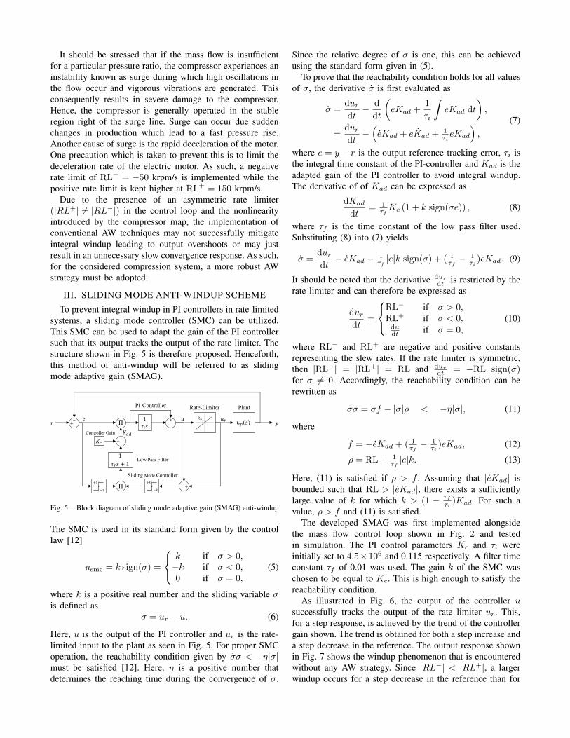
III. SLIDING MODE ANTI-WINDUP SCHEME
To prevent integral windup in PI controllers in rate-limitedsystems, a sliding mode controller (SMC) can be utilized.This SMC can be used to adapt the gain of the PI controllersuch that its output tracks the output of the rate limiter. Thestructure shown in Fig. 5 is therefore proposed. Henceforth,this method of anti-windup will be referred to as slidingmode adaptive gain (SMAG).
1
𝜏𝑖𝑠𝑟 𝑦
𝑒 𝑢𝑟
Plant
−+
Rate-Limiter
𝑢 𝑅𝐿
+−
Π
Π
++ 𝐺𝑝 𝑠
++𝐾𝑐
1
𝜏𝑓𝑠 + 1
PI-Controller
Sliding Mode Controller
−𝑘
+𝑘
Low Pass Filter
Controller Gain 𝐾𝑎𝑑
−1
+1
Fig. 5. Block diagram of sliding mode adaptive gain (SMAG) anti-windup
The SMC is used in its standard form given by the controllaw [12]
usmc = k sign(σ) =
k if σ > 0,−k if σ < 0,0 if σ = 0,
(5)
where k is a positive real number and the sliding variable σis defined as
σ = ur − u. (6)
Here, u is the output of the PI controller and ur is the rate-limited input to the plant as seen in Fig. 5. For proper SMCoperation, the reachability condition given by σσ < −η|σ|must be satisfied [12]. Here, η is a positive number thatdetermines the reaching time during the convergence of σ.
Since the relative degree of σ is one, this can be achievedusing the standard form given in (5).
To prove that the reachability condition holds for all valuesof σ, the derivative σ is first evaluated as
σ =durdt− d
dt
(eKad +
1
τi
∫eKad dt
),
=durdt−(eKad + eKad + 1
τieKad
),
(7)
where e = y − r is the output reference tracking error, τi isthe integral time constant of the PI-controller and Kad is theadapted gain of the PI controller to avoid integral windup.The derivative of of Kad can be expressed as
dKad
dt= 1
τfKc (1 + k sign(σe)) , (8)
where τf is the time constant of the low pass filter used.Substituting (8) into (7) yields
σ =durdt− eKad − 1
τf|e|k sign(σ) + ( 1
τf− 1
τi)eKad. (9)
It should be noted that the derivative durdt is restricted by the
rate limiter and can therefore be expressed as
durdt
=
RL− if σ > 0,RL+ if σ < 0,dudt if σ = 0,
(10)
where RL− and RL+ are negative and positive constantsrepresenting the slew rates. If the rate limiter is symmetric,then |RL−| = |RL+| = RL and dur
dt = −RL sign(σ)for σ 6= 0. Accordingly, the reachability condition can berewritten as
σσ = σf − |σ|ρ < −η|σ|, (11)
where
f = −eKad + ( 1τf− 1
τi)eKad, (12)
ρ = RL + 1τf|e|k. (13)
Here, (11) is satisfied if ρ > f . Assuming that |eKad| isbounded such that RL > |eKad|, there exists a sufficientlylarge value of k for which k > (1 − τf
τi)Kad. For such a
value, ρ > f and (11) is satisfied.The developed SMAG was first implemented alongside
the mass flow control loop shown in Fig. 2 and testedin simulation. The PI control parameters Kc and τi wereinitially set to 4.5×10⁶ and 0.115 respectively. A filter timeconstant τf of 0.01 was used. The gain k of the SMC waschosen to be equal to Kc. This is high enough to satisfy thereachability condition.
As illustrated in Fig. 6, the output of the controller usuccessfully tracks the output of the rate limiter ur. This,for a step response, is achieved by the trend of the controllergain shown. The trend is obtained for both a step increase anda step decrease in the reference. The output response shownin Fig. 7 shows the windup phenomenon that is encounteredwithout any AW strategy. Since |RL−| < |RL+|, a largerwindup occurs for a step decrease in the reference than for

0 2 4 6 8 10 12
Time (s)
0
2000
4000
6000
Kad
0 2 4 6 8 10 12
Time (s)
1.6
1.8
2
2.2
2.4
2.6105
uu
r
Fig. 6. SMAG anti-windup response to references step changes
2 4 6 8 10 12
Time (s)
3
4
5
6
7
8
9
10
11
12
13
14
Mas
s F
low
(g/
s)
ReferenceWithout AntiwindupSMAG Antiwindup
Fig. 7. Output response with and without SMAG anti-windup to referencestep changes
a step increase. The developed SMAG does however nullifythis effect. During the ramp up/down phase when σ = 0, thePI controller does not windup since the input to the systemur is essentially the same as the controller output u. Thiscontinues until Kad = Kc after which the rate limiter nolonger influences the behavior of the system.
IV. TUNING OF PI CONTROLLERS INRATE-LIMITED SYSTEMS
In tuning the flow-rate controller of the system in Fig. 1,two challenges are presented. First is that standard tuningmethods, such as relay-based tuning methods, cannot be di-rectly applied due the existence of a rate limiter in the controlloop which interferes with the tuning process. Therefore, itis critical to analyze the impacts of this rate limiter on tuningmethods. This was done using the describing functionsmethod of analysis. Second is that, since the compressor mapintroduces a nonlinearity, tuning must be done for differentoperating conditions. A gain schedule can then be setup toincrease the robustness of the control approach. Otherwise,parameters obtained for one operating condition might leadto instability in other conditions.
A. Relay Feedback Test of Rate-Limited Systems
In the standard Astrom-Hagglund relay-feedback test(RFT), oscillations are created at the negative real axis ofthe complex plane. The resultant frequency and amplitudeof the oscillations are then used with tuning laws such asZiegler-Nichols to calculate PI control parameters. However,if a rate limiter is incorporated, a phase lag is introduced. Tocounteract this phase lag, the standard RFT can be alteredto include an additional derivative term as shown in Fig. 8.The use of a low pass filter with the derivative is unnecessarybecause the rate-limiter itself acts as a filter and attenuateshigh frequency components.
−𝑐
+𝑐
𝐺𝑝 𝑠𝑟 𝑦𝑥 𝑢𝑟
Relay Plant
−+
Rate-Limiter
𝑢 𝑅𝐿
𝑠
Derivative
++
𝑘𝑝
Fig. 8. RFT with additional derivative term in rate-limited system
The RFT presented in Fig. 8 with the additional derivativeterm can be analyzed via the describing functions (DF)method. Here, the combined nonlinearity of both the relayand rate-limiter along with the gain kp and derivative are allexpressed as a complex gain. Since the derivative and ratelimiters are essentially dynamic (affected by frequency of x),the DF, N(a, ω), will be a function of both amplitude a andfrequency ω of the resultant oscillations. For simplicity, itcan be assumed that the rate limiter is symmetric and thatthe relay output c is large enough such that the rate limiteris always acting.
Consider now the case where the parameter kp of the test,shown in Fig. 8, is quite high such that the derivative termis dropped. This imitates the standard RFT. In this scenario,the DF can be derived as
N(a, ω) = j4
πa
∫ π2
0
(2arπψ − ar
)cosψ dt,
= −j 8
π2
ara,
(14)
where ar denotes the amplitude of oscillations of the triangu-lar output signal of the rate limiter. For large values of c, ar isa direct function of the frequency ω and the slew-rate RL andcan be calculated as ar = πRL
2ω . Accordingly, the negativereciprocal of the describing function can be expressed as
−N−1(a, ω) = −j πaω4RL
. (15)
The harmonic balance equation (HBE) given
Gp(jω0) = −N−1(a0, ω0) (16)
can then be solved to find the frequency ω0 and amplitude a0of the excited oscillations. Since −N−1(a, ω) is a negativeimaginary number, if the standard RFT is used without aderivative term, limit cycles are created on the negativeimaginary axis. Hence, the standard RFT is not suitable forPI controller tuning.

Consider now the impact of the additional derivative term.By introducing an additional derivative term to the standardRFT as shown in Fig. 8, limit cycles can be created atan angle φ from the negative real axis. This is due to thephase shift introduced by the derivative term which can beevaluated as
φ = arctan
(kpω
). (17)
It should be noted that the gain of the combined nonlinearityremains the same since the rate limiter essentially imposesa saturation on the rate which is a function of the amplitudea and frequency ω. Accordingly,
|N(a, ω)| =∣∣∣∣4RL
πaω
∣∣∣∣ . (18)
Through expressing the N(a, ω) in rectangular coordinates,the describing function with the additional derivative termbecomes
N(a, ω) =4RL
πaγ
(1− j kp
ω
), (19)
−N−1(a, ω) = − πaγ4RL
(1 + j
ω
kp
), (20)
whereγ =
√ω2 + k2p.
To compensate for the 90 phase shift caused by the ratelimiter nonlinearity, the phase φ is set to zero by selecting aproportional gain kp of zero.
B. Optimal Tuning
To generate optimal tuning laws for the considered com-pression system, it is convenient to first obtain a linearizedtransfer function representation which approximates of thenonlinear process. Most commonly, the first-order plus deadtime (FOPDT) transfer function given by Ke−sθ
τs+1 is used.However, in this work, a second-order plus dead time(SOPDT) given by
Gpl(s) =Kple
−sθpl
τ2pls2 + 2ξτpls+ 1
(21)
is used, which better approximates the dynamics of the com-pression process. System identification can be done usingthe RFT with the additional derivative term shown in Fig. 8by selecting different valves of kp and exciting oscillationsat different frequencies. It is important to note that for theconsidered compression system, the dynamics are primarilyintroduced by the motor. Through system identification, itcan be shown that, throughout all the operating conditions(Wcp and PR) the motor response from N∗
cp to Ncp canbe approximated by a SOPDT transfer function with theparameters
τpl = 0.15, θpl = 0.05, ξ = 0.7.
The motor dynamics impose a gain of one since at steadystate N∗
cp = Ncp. Furthermore, in a small domain of
operating conditions, the compressor map from Ncp to Wp
can be can be represented by
Wcp = KmapNcp +Wo, (22)
where Wo represents a certain bias and Kmap is a gain. Thebias Wo can be considered to be a disturbance and ignoredsince it does not affect the required tuning parameters.
In [9], homogeneous tuning rules for PID controllers wereproposed. In a similar fashion, for systems with rate-limitedactuators, the following rules can be used
Kc = c14RL
πa0 ω0, τi = c2
2π
ω0. (23)
Here c1 and c2 are constants that define the tuning law tobe used. The idea behind (23) is to express the controlparameters as homogeneous functions of the critical gain4RLπa0ω0
and the critical period 2πω which are defined at an
angle φc from the negative real axis. This is done to accountfor the phase shift introduced by the controller. The phaseshift φc can be evaluated as
φc = −arctan
(1
2πc2
). (24)
The compression system in Fig. 1 can be linearized fora small domain of operating conditions (Wcp and PR) andapproximated by (21). For a SOPDT system having ξ = 0.7and a ratio θ
τ = 13 , the optimal tuning to have the minimum
integral absolute error (IAE) with a gain margin of 3 is c1 =0.317 and c2 = 0.488. For this tuning rule, the phase shiftcan be calculated using (24) as φc = −18.0.
Using the RFT with an additional derivative term as shownin Fig. 8 for a rate-limited system is an iterative process.First, the closed-loop system is allowed to reach steady-stateoscillations from which the frequency ω0 is measured andφ is calculated using (17). The gain kp is then increased ordecreased and φ is recalculated for the new ω0. This processis repeated until the φ = −φc = −18.0, at which pointthe amplitude a0 of output oscillations is measured. Theparameters of the PI controller are then calculated using (23).This yields the optimal parameters at one operating pointin the compressors map and can be repeated for differentconditions.
C. Gain Scheduling
The proposed RFT was applied at a number of selectedoperating conditions (PR and Wcp). It is noteworthy that forthe considered simulation model, the system time constantsdo not change at different points of operation; rather, onlythe gain of the compressor map varies. Consequently, thevalue of τi does not vary while Kc changes with theoperating conditions. Applying the proposed RFT yieldsτi = 0.274. The values of Kc obtained for different pointson the compressor map are can be used in to set-up a gainschedule for added robustness to the control loop. A smoothapproximation can made to fit the data points using
Kc(Wcp, PR) = (1.13− 11.3Wcp − 1.42PR
− 143W 2cp + 18.0PRWcp + 0.41PR2)× 108. (25)

V. OPTIMALLY TUNED GAIN SCHEDULEDPI CONTROLLER WITH SMAG
0 5 10 15 20 25
Time (s)
4
6
8
10
12
14
16
Mas
s F
low
-Rat
e (g
/s)
ReferenceStandard PIStandard PI with SMAGOptimal PI with SMAGOptimal Gain Scheduled PI with SMAG
0 5 10 15 20 25
Time (s)
1
1.5
Pre
ssur
e R
atio
(-)
Fig. 9. Response of mass flow-rate for different control strategies
In the considered rate limited system, integral windupcan be avoided by selecting a very small controller gain.However, this results in an unnecessarily slow response.Using the proposed SMAG strategy for AW was shownto successfully avoid wind-up when using higher controllergains leading to faster convergence. However, to ensure thatthe PI controller behaves optimally when the rate limiter isnot saturated, it can be tuned using an RFT with an additionalderivative term to compensate for the phase lag introducedby the rate limiter. This ensures that a predefined gain marginis obtained and leads to the best performance (lowest IAE)at that margin. This, however, applies for a linear plant.Since a compressor behaviors in a nonlinear fashion, tuningmust be carried out at different operating conditions ofmass flow and pressure ratio and a gain schedule must beconstructed. Not doing so can alter the gain margin or evenresult in instabilities under different operating conditions,for example, at higher pressure ratios. This shown by theresponse of the PI controller which was optimized at alow pressure ratio and was not implemented with a gainschedule. It can be seen in Fig. 9 that this controller lead toan instability at higher pressure ratios. The output responsespresented in Fig. 9 highlights the need and effects of SMAG,optimal tuning and gain scheduling on the control of the massflow-rate of the centrifugal compressor.
VI. CONCLUSION
To cope with systems having rate-limited actuators, thedeveloped SMAG anti-windup strategy can be adopted. Thisensures that the PI controller operates at the actuators’rate-limit while avoiding integral windup during transients.The topology is also quite flexible as it does not requireknowledge of plant dynamics; rather, only the rate-limitimposed. Furthermore, to tune the PI controller, a systematic
method was devised. This method can also be utilized insystems without rate limiters as a more lenient alternativeto the standard RFT. By following the tuning procedurediscussed in this paper, the optimal control parameters canbe obtained for the rate-limited system.
REFERENCES
[1] G. Herrmann, M. C. Turner, I. Postlethwaite, and G. Guo, “Practicalimplementation of a novel anti-windup scheme in a HDD-dual-stageservo-system,” IEEE/ASME Transactions on Mechatronics, vol. 9,no. 3, pp. 580–592, 2004.
[2] G. Grimm, J. Hatfield, I. Postlethwaite, A. R. Teel, M. C. Turner,and L. Zaccarian, “Antiwindup for stable linear systems with inputsaturation: an LMI-based synthesis,” IEEE Transactions on AutomaticControl, vol. 48, no. 9, pp. 1509–1525, 2003.
[3] T. Hu, A. R. Teel, and L. Zaccarian, “Regional anti-windup compen-sation for linear systems with input saturation,” in Proceedings of theAmerican Control Conference, June 2005, pp. 3397–3402 vol. 5.
[4] C. Pittet, S. Tarbouriech, and C. Burgat, “Stability regions for linearsystems with saturating controls via circle and Popov criteria,” inProceedings of the 36th IEEE Conference on Decision and Control,vol. 5, Dec 1997, pp. 4518–4523 vol.5.
[5] Y. Y. Cao and Z. Lin, “An anti-windup design for polytopic systems bya parameter-dependent Lyapunov function approach,” in InternationalConference on Control and Automation, vol. 1, June 2005, pp. 541–546 Vol. 1.
[6] F. Garelli, R. J. Mantz, and H. Battista, Advanced control for con-strained processes and systems. The Institution of Engineering andTechnology, 2011.
[7] F. Garelli, P. Camocardi, and R. J. Mantz, “Variable structure strategyto avoid amplitude and rate saturation in pitch control of a windturbine,” International Journal of Hydrogen Energy, vol. 35, no. 11,pp. 5869–5875, 2010.
[8] K. Astrom and T. Hagglund, PID Controllers: Theory, Design andTuning. Instrument Society of America, 1995.
[9] I. Boiko, Non-parametric tuning of PID controllers. Springer, 2013.[10] C. C. Yu, Autotuning of PID controllers: a relay feedback approach.
Springer Science & Business Media, 2006.[11] J. T. Pukrushpan, A. G. Stefanopoulou, and H. Peng, Control of
fuel cell power systems: principles, modeling, analysis and feedbackdesign. Springer Science & Business Media, 2004.
[12] Y. Shtessel, C. Edwards, L. Fridman, and A. Levant, Sliding ModeControl and Observation, ser. Control Engineering. Springer NewYork, 2013.