slope stability 2013.12.020
TRANSCRIPT
7232019 Slope Stability 201312020
httpslidepdfcomreaderfullslope-stability-201312020 114
Stability analysis of slopes against combined circularndashtoppling failure
E Mohtarami n A Jafari M Amini
School of Mining Engineering University of Tehran PO Box 14395-515 Tehran Iran
a r t i c l e i n f o
Article history
Received 11 September 2012Received in revised form15 October 2013
Accepted 31 December 2013
Keywords
Circular failureToppling failureRock slopeInteraction between soil and rockLimit equilibrium theoryPlasticity
a b s t r a c t
Circular failure is one of the most probable instabilities on slopes with severely crushed rock or soilslopes Another type of instability is blockndash1047298exural toppling which is the most common type of topplingfailure In this type of failure some rock blocks are broken by bending and other topples due to theirweight In some slopes a soil mass has direct contact with the rock mass with the potential of blockndash
1047298exural failure If so the total slope failure potential is the combination of circular ndashtoppling failure Thisinstability can be called secondary toppling failure for which there is no solution available in theliterature Studies on circular and toppling failure are reviewed Then the interaction between soil massand rock blocks is studied Considering the interaction between soil and rock this study proposes atheoretical model for stability analysis for the combination of circularndashtoppling failure and the requiredequations are developed Solving these equations manually is time-consuming thus a special computercode is programmed to analyze the combination failure The code receives slopes information from theuser and calculates the factor of safety subject to combination failure circumstances Finally a real case(instability of a slope in Vana village along Haraz road in northern Iran) is analyzed with this code andresults are compared with the observed data
amp 2014 Elsevier Ltd All rights reserved
1 Introduction
Possible instabilities in rock slopes consist of several typesdepending on loading conditions rock mass properties excavationgeometry and topography One type of these instabilities istoppling failure It is generally divided into 1047298exural blocky andblockndash1047298exural toppling [1] If the rock mass consists of just a set of steep discontinuities and direction of these discontinuities isparallel or almost parallel to the slope rock slope acts as cantileverbeams located on each other (each of beams connected at theirbase to bed rock is named column) In such a case if tensile stressdue to bending which is caused by the columns weight exceedsthe tensile strength the rock columns are broken down Thisinstability is called 1047298exural toppling If rock mass has anotherdiscontinuity parallel to the direction of slope but steeper than
the slope the columns are separated from their base and formblocks The rock blocks do not withstand the bending stress andmay tend to topple under the weight force components This typeof failure is called blocky toppling Above pure state they arerarely observed in real cases and most toppling failure is in theform of blockndash1047298exural which is the combination of blocky and1047298exural toppling [2] In this failure some columns are broken by1047298exural stress and some are overturned by the weight
Despite extensive studies on blocky and 1047298exural toppling very
few studies have been done on blockndash1047298exural toppling failure [2]Also in all provided relationships the weight of the columns isassumed as the main cause of failure But in some cases secondaryfactors other than the columns weight are the main cause of failure (earthquake force force caused by the rapid drop in watertable force from the soil mass behind the rock slope) In situationswhere soil mass behind the slope has the potential of circularfailure it stimulates the rock mass and intensi1047297es the blockndash
1047298exural toppling failure This type of failure which is a combina-tion of circular and blockndash1047298exural toppling can be described ascombined circularndashtoppling failure In this paper a new methodfor analyzing this type of failure is provided using the limitequilibrium equations
2 Individual and combined failure modes
21 Literature review
a) Circular failure In 1846 Colin after reviewing a large numberof circular failures obtained a general form of this type of failure as cycloid arc [3] Another approach was presented byTaylor [4] For a long time it was the only method available forstability assessment in soil This procedure is known as thefriction circle method This method and other methods whichconsider the medium subject to instability as a kind of homo-geneous soil were not accurate enough and could not satisfy
Contents lists available at ScienceDirect
journal homepage wwwelseviercomlocateijrmms
International Journal of Rock Mechanics amp Mining Sciences
1365-1609$- see front matter amp 2014 Elsevier Ltd All rights reserved
httpdxdoiorg101016jijrmms201312020
n Corresponding authorE-mail address mohtaramiutacir (E Mohtarami)
International Journal of Rock Mechanics amp Mining Sciences 67 (2014) 43 ndash56
7232019 Slope Stability 201312020
httpslidepdfcomreaderfullslope-stability-201312020 214
users in many cases In 1916 Petterson introduced a method fordividing the soil into a number of ldquopartial volumesrdquo Thismethod is known as the method of slices or the Swedishmethod This method was implemented by Fellenius in theanalysis of circular failure [5] In these methods the effectiveforce on the bottom of sliding slice was only its weight ThenBishop proposed a method by considering forces acting onsides of slices in which a more accurate calculation was
provided for the safety factor [6] Previous methods wereapplied in a circular sliding surface Nonveiller extended themethod for mass with arbitrary shape and under the in1047298uenceof external forces (overburden water 1047298ow andhellip) [7] The onlydisadvantage of this method was that the equilibrium of moments was ignored in each slice Finally Morgenstern andPrice provided another solution in which the entire equilibriumstate was satis1047297ed [8] as generalized more by Chen andMorgenstern This method suggested that the internal forcesbetween the blocks on the 1047297rst and last slices were parallelwith the overall failure plane [9]
b) Toppling failure In 1968 Muller for the 1047297rst time suggestedthat block rotation could have contributed in the failure of thenorth face of the Vaiont slide [10] Then Ashby proposed asimple solution for the analysis of the rotation of rock blockHe was the one who for the 1047297rst time proposed the termldquotopplingrdquo for such instabilities [11] Hafmann carried out anumber of model studies in the laboratory under Mullersdirections and concluded that this type of failure could occurin nature [12] Goodman and Bray based on regional observa-tions and laboratory modeling classi1047297ed the toppling failure intwo primary and secondary modes [1] The main factor causinginstability is the weight of the rock mass in primary topplingfailure while in the secondary toppling failure external factorsother than the weight is the cause of failure In 1976 Goodmanand Bray presented an adequate analytical solution for theevaluation of blocky toppling failure This approach was pre-sented by several researchers as computer codes and diagramsfor the rapid analysis of rock slopes with blocky toppling failure
potential [13ndash19] Although their solution was useful in theorymany parameters were ignored by it On the other hand theonly two preventing factors against failure were friction andcohesion at the rock contacts Zaruba and Mencl reported anactual 1047298exural toppling failure in Switzerland [20] This reportconvinced many researchers that 1047298exural toppling was anindependent failure mode in rock slopes Since then the1047298exural toppling has been modeled widely [21ndash26] Aydanand Kawomoto modeled this phenomenon with base friction
apparatus in laboratory and offered a new analytical approach[21] In this method the concept of safety factor was improvedslightly but the only slope instability factor was the weight of blocks Adhikary et al compared the results of this analyticalsolution with those of centrifuge modeling [22ndash24] Aydan andAmini based on the principles of the compatibility and initialequilibrium equations presented another approach for theevaluation of 1047298exural toppling failure [25] The results of this
method were veri1047297ed with Aydan and Kawomoto and theAdhikary modeling By nature most toppling failures are acombination of blocky and 1047298exural toppling while this isdisregarded by the previous methods Amini et al studied thistype of failure and offered a proper analytical solution for theirevaluation [2] In fact this approach combined techniques of Aydan-Kawomoto and GoodmanndashBray however the role of external forces was not included in slope stability
22 Limitation of previous methods and contributions
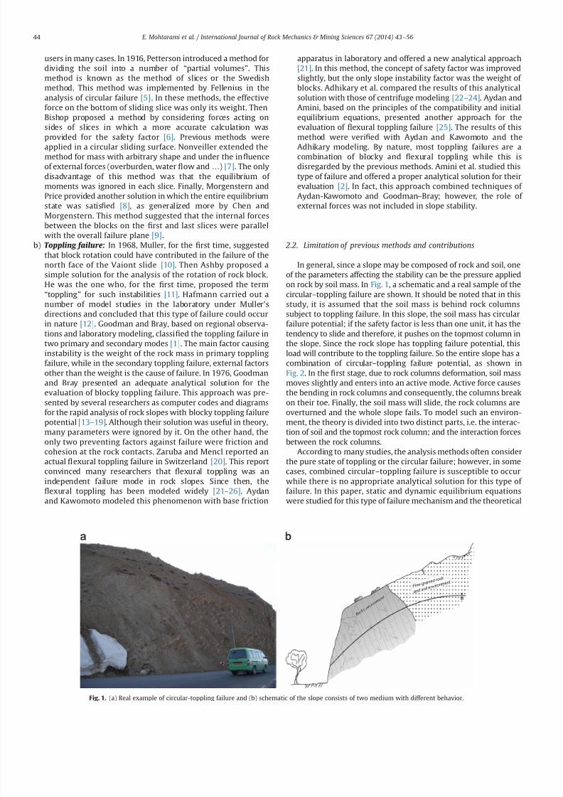
In general since a slope may be composed of rock and soil oneof the parameters affecting the stability can be the pressure appliedon rock by soil mass In Fig 1 a schematic and a real sample of thecircularndashtoppling failure are shown It should be noted that in thisstudy it is assumed that the soil mass is behind rock columnssubject to toppling failure In this slope the soil mass has circularfailure potential if the safety factor is less than one unit it has thetendency to slide and therefore it pushes on the topmost column inthe slope Since the rock slope has toppling failure potential thisload will contribute to the toppling failure So the entire slope has acombination of circularndashtoppling failure potential as shown inFig 2 In the 1047297rst stage due to rock columns deformation soil massmoves slightly and enters into an active mode Active force causesthe bending in rock columns and consequently the columns breakon their toe Finally the soil mass will slide the rock columns areoverturned and the whole slope fails To model such an environ-
ment the theory is divided into two distinct parts ie the interac-tion of soil and the topmost rock column and the interaction forcesbetween the rock columns
According to many studies the analysis methods often considerthe pure state of toppling or the circular failure however in somecases combined circularndashtoppling failure is susceptible to occurwhile there is no appropriate analytical solution for this type of failure In this paper static and dynamic equilibrium equationswere studied for this type of failure mechanism and the theoretical
R o c k y
e n v i r o
n m e n t
Fine-grain
ed rock
and soil en
vironmen t
Fig 1 (a) Real example of circular-toppling failure and (b) schematic of the slope consists of two medium with different behavior
E Mohtarami et al International Journal of Rock Mechanics amp Mining Sciences 67 (2014) 43ndash56 44
7232019 Slope Stability 201312020
httpslidepdfcomreaderfullslope-stability-201312020 314
solution was developed The equations were then solved within auser friendly environment (Turbo C thorn thorn) as a computer code toease the computation process
3 Estimation of the soil pressure
Consider soil mass in contact with the retaining wall A soilelement located at depth z is subjected to a vertical effectivepressure s0
0 and a horizontal effective pressure s0h The ratio of s0
h
to s00 can be de1047297ned as a non-dimensional quantity k Now three
possible cases may arise concerning the retaining wall [26]
1) The wall does not move either to the right or to the left of itsinitial position So the soil mass will be in a state of staticequilibrium in which k frac14 k0 where k0 is at-rest earth pressurecoef 1047297cient (Fig 3a)
2) The wall rotates suf 1047297ciently about its bottom to the free spaceand soil will reach a state of plastic equilibrium In this casek frac14 ka where ka is active earth pressure coef 1047297cient (Fig 3b)
3) The wall rotates suf 1047297ciently about its bottom to the 1047297lled spacewith soil In this case k frac14 k p where k p is passive earth pressurecoef 1047297cient (Fig 3c)
As stated in the previous section in circularndashtoppling failure
mode circular sliding of soil stimulates the blockndash1047298exural toppling
failure According to Rankine theory if a nearly rigid column (forexample one made of reinforced concrete) is located in front of soilmass with slide potential as a retaining wall a very small horizontalstrain in the rigid column (less than 05) leads to the activemovement on the soil mass In the circularndashtoppling failure thetopmost rock column acts as a cantilever retaining wall and inthe case of small displacement occurring in rock columns during theexcavation the soil mass takes the active mode In fact withassuming active earth pressure for soil the rotation of topmost blockis considered implicitly However the active force is the minimumforce that the soil may apply to the wall So the question is whether it
is necessary to check the wall for possible greater forces It should beconsidered as long as the soil mass is composed of a material withknown friction angle when the applied force to the wall is equal tothe theoretical active force This entry has been shown with accuratetests by Terzaghi from Ref [27] As expected when the wall was notprotected the applied forces were larger than the active force butwith releasing and partial movement of wall the applied forces wereequal to the active force Therefore assuming the active earthpressure for soil the effect of blocks rotation is actually consideredIf the rock blocks do not rotate not only does it not mean there is aproblem but also that the blocks are much stronger than therequired amount for soil If the rotation is achieved the activemode is created and theoretical forces are correct However evi-dence obtained from practical case study indicates that the soil is in
active mode in this case
Failure initiation Failure occurrence in rock and soilPrior to Failure
Failure stages
Fig 2 Stages of the circularndashtoppling failure
Fig 3 De1047297nition of (a) at-rest (b) active and (c) passive pressures [26]
E Mohtarami et al International Journal of Rock Mechanics amp Mining Sciences 67 (2014) 43ndash56 45
7232019 Slope Stability 201312020
httpslidepdfcomreaderfullslope-stability-201312020 414
A shear force is mobilized in the contact surface of the soil withrock column which is controlled by friction angle between soiland wall ethδ THORN and their cohesion (α ) Fig 4a shows outline failurewith the Sokolovski method
Pressure on a rock wall due to the soil mass can be obtainedusing Rankin or Coulombs method Due to overestimation bythese theories in the passive mode Caquot and Kerisel proposedsome tables for obtaining the coef 1047297cient of earth pressure for non-planar surface failure [28] Janbu and later Shields and Toluanyused the slice method for the estimation of soil pressure [2930]Sokolovski presented a 1047297nite difference solution using a mathe-matical method [31] All these methods calculate more realisticvalues for the passive coef 1047297cient of soil pressure But none of them can improve the calculation of active coef 1047297cient pressuresubstantially Rosenfarb and Chen considered various failure
surfaces and combined them with logarithmic layer mechanismTheir 1047297ndings are very consistent with Sokolovskis solutionwhich is widely accepted by other researchers [32] Consideringthe proper velocity component for this mechanism and using thefollowing complement assumptions one can obtain the coef 1047297cientof active earth pressure
1 The soil is idealized as a perfectly plastic material This materialobeys the Coulomb failure criteria and its associated 1047298ow rule
2 In limit analysis states a soil mass will collapse if there is anycompatible pattern of plastic deformation for which the workrate of the external loads exceeds the rate of internal energydissipation due to shearing of the soil [33]
3 Velocity vectors are perpendicular to border line in logarithmic
spiral zone But in active pressure condition a velocity (V 0) isconsidered for the retaining wall with inclination (η) to thehorizontal This angle is usually assumed zero (when theretaining wall is almost vertical) But if the retaining wall isonly toppled in its toe and it is suf 1047297ciently rigid it does nothave the axial strain in this process (commonly) and itsinclination is far from the vertical mode This angle is perpen-dicular to the surface of the retaining wall (it depends on θ which is Deviation angle of the rock column from the vertical)
4 For cohesion less soil only dissipation occurs at the soilndashwallinterface but in cohesion soil this phenomenon also occursdue to shearing
Considering several sectors that divide the failure zone in
which the velocity vector of each sector is the direction at an
angle ϕs to the discontinuous rigid boundary and equating the
rate of the external work to the rate of internal energy dissipationone can obtain a closed form expression for the resultant coef 1047297-cient of active pressure as Eqs (1) to (4) By considering soilfriction angleϕs Eqs (1) and (2) are for non-cohesive soil mass andfor a smooth wall ethδ oφsTHORN and rough wall ethδ frac14 φsTHORN respectively Eqs(3) and (4) are for cohesive soil mass with smooth and rough wallrespectively In Fig 4b soil mass behavior is shown schematically
ksaγ frac14
sec δ cos θ thorn tan δ sin θ frac12 tan δ sin ethθ thorn ρηTHORN= cos ρ
tan ρ cos eth ρthornϕsTHORN sin ethθ thorn ρηTHORN
cos θ cos ϕs
thorn cos 2eth ρthornϕsTHORN
cos ρ cos θ cos 2ϕseth1 thorn9tan 2ϕsTHORN
sin ethθ thorn ρηTHORNfrac123 tan ϕs thorneth sin ξ 3 tan ϕs cos ξ THORNexpeth 3ξ tan ϕsTHORN
thorn cos ethθ thorn ρηTHORNfrac121 eth 3 tan ϕs sin ξ thorn cos ξTHORNexpeth 3ξ t an ϕsTHORN
( )
thorn cos 2eth ρthornϕsTHORN cos ethθ thorn ρηthornξ β THORN sin ethθ thorn ρηthornξTHORNexpeth 3ξ tan ϕ sTHORN
cos ϕs cos θ sin ethθ thorn ρηthornξthornϕs β THORN cos ρ
0BBBBBBBBB
1CCCCCCCCCA
eth1THORN
kr aγ frac14
sec δ cos θ thorn tan δ sin θ
sin 2 ρ cos eth ρthornϕsTHORN sin ethθ thorn ρηTHORN cos ethθ thornϕs THORN
cos 2θ cos ϕs cos eth ρϕsTHORN
cos 2eth ρthornϕsTHORN cos ethθ thornϕs THORN
cos 2θ cos 2ϕseth1 thorn 9tan 2ϕsTHORN cos eth ρϕsTHORN
sin ethθ thorn ρηTHORNfrac123 tan ϕs thorneth sin ξ 3 tan ϕs cos ξ THORNexpeth 3ξ tan ϕsTHORN
thorn cos ethθ thorn ρηTHORNfrac121 eth 3 tan ϕs sin ξ thorn cos ξTHORNexpeth 3ξ t an ϕsTHORN
( )
thorn cos 2eth ρthornϕsTHORN cos ethθ thorn ρηthornξ β THORN sin ethθ thorn ρηthorn ξTHORN cos ethθ thornϕsTHORNexpeth 3ξ tan ϕsTHORN
cos 2θ cos ϕs sin ethθ thorn ρηthornξthornϕs β THORN cos eth ρϕsTHORN
0BBBBBBB
1CCCCCCCA
eth2THORN
ksac frac14
sec δ cos θ thorn tan δ sin θ frac12 tan δ sin ethθ thorn ρηTHORN= cos ρ
tan ρthorn
cos eth ρthornϕsTHORN cos ethθ thorn ρηthornξ β THORNexpeth ξ tan ϕ sTHORN
cos ρ sin ethθ thorn ρηthornξthornϕs β THORN
cos eth ρthornϕsTHORNfrac12expeth 2ξ tan ϕsTHORN 1
sin ϕs cos ρ
eth3THORN
kr ac frac14
sec δ cos θ thorn tan δ sin θ
cos ϕs sin ethθ thorn ρηTHORNcos θ cos eth ρϕsTHORN
thorn sin ρ cos ethθ thornϕs THORNcos θ cos eth ρϕs THORN
thorn
cos eth ρthornϕs THORN cos ethθ thornϕsTHORN cos ethθ thorn ρηthorn ξ β THORNexpeth ξ tan ϕsTHORNcos θ sin ethθ thorn ρηthorn ξthornϕs β THORN cos eth ρϕs THORN
cos eth ρthornϕsTHORN cos ethθ thornϕs THORNfrac12expeth 2ξ tan ϕsTHORN 1
sin ϕs cos θ cos eth ρϕs THORN
8gtgtgtltgtgtgt
9gtgtgt=gtgtgt eth4THORN
where ksaγ and k
r aγ are the active coef 1047297cients of non-cohesive soil
for smooth wall and rough wall respectively ksac and kr
ac are theactive coef 1047297cients of cohesive soil for smooth wall and rough wall
respectively We show these four variables with ka Parameters δ θ
ρ
δ
ψ
ξ
β
φ
φθη
φ
δστ =
Fig 4 (a) The slip lines and the failure area based on Sokolovski method [31] and (b) plastic stress areas for the active soil pressure mode using the theory of plasticity
E Mohtarami et al International Journal of Rock Mechanics amp Mining Sciences 67 (2014) 43ndash56 46
7232019 Slope Stability 201312020
httpslidepdfcomreaderfullslope-stability-201312020 514
β η ϕs ρ and ξ represent the friction angle between soil and rockmass deviation angle of rock column from the vertical inclinationof soil surface inclination of velocity vector of the retaining wall
the internal soil friction angle the angle between the lower boundof soil plastic zone and the upper bound of the last block Theangle between the lower and the upper bound of soil plastic zoneis shown in Fig4
To calculate the force on the topmost rock column the activecoef 1047297cient of soil mass must be 1047297rst calculated according to realconditions (one of the above four states) Eqs (1)ndash(4) should besolved for the maximum amount of ka Determination of the
maximum amount of ka depends on two variables ρ and ξ If β frac14 δ frac14 0 the results of the proposed equations are the same asRankine and Coulombs methods However this solution givesmore accurate results when the soil friction angle ethφsTHORN is greaterthan 351 and δ is about ϕ=2 or more and β a0 comparing toRankine and Coulombs methods
To evaluate the accuracy in the results of the proposed methodthey are compared with the results of 1047297nite element method andCoulomb methods (Table 1) By changing the angle of the retainingwall and soil friction angle a stress is obtained which acts on thewall in a certain depth in three methods Fig 5andashc shows thegeometry of the constructed models in Plaxis 3D Tunnel [34] If thenumerical answers are considered accurate the errors presentedin Table 1 belong to Coulomb and the proposed method ascompared to the numerical method It can be seen that the errorof Coulombs method increases with reducing the angle of theretaining wall Instead the error of the proposed theory remains inthe acceptable range
When the active coef 1047297cient of the soil mass ethkaTHORN is calculatedfrom one of above equations the force on the topmost rock
Table 1
Comparison of Coulomb and proposed methods results with numerical method
θ
(degree)ϕs
(degree)Depth(m)
FEM(KNm 2)
Coulomb(KNm 2)
Error of Coulomb()
Offeredtheory(KNm 2)
Error of offeredtheory()
0 20 6687 59881 57030 0048 59762 000240 6708 37265 27201 0270 36184 0029
5 20 6715 83122 78417 0057 81459 002040 6715 39610 36847 0070 38818 0020
10 20 6881 88358 82965 0061 89242 001040 6881 41842 38671 0076 41340 0012
15 20 6618 87411 81693 0065 85838 001840 6618 41591 38122 0083 40510 0026
20 20 6473 88573 82164 0072 86713 002140 6473 42098 38305 0090 40961 0027
25 20 6705 95639 87985 0080 94109 001640 6705 4 5196 40571 0102 44473 0016
30 20 6386 94705 86489 0087 92432 002440 6386 4 5187 39989 0115 43741 0032
35 20 6652 103092 93296 0095 100721 002340 6652 4 9460 42638 0138 48125 0027
40 20 6587 107245 96011 0105 104992 002140 6601 52522 43769 0167 50947 0030
(KNm 2)
0000
-10000
10000
-20000
-30000
-40000
-50000
-60000
-70000
-80000
-90000
-100000
-110000
-120000
Fig 5 (a) Displacement of soil and wall with θ frac14251 and ϕfrac14201 (b) displacement of soil and wall with θ frac14251 and ϕfrac14401 and (c) stress distribution and deformation in
model with ϕfrac14401 and ϕfrac14201
E Mohtarami et al International Journal of Rock Mechanics amp Mining Sciences 67 (2014) 43ndash56 47
7232019 Slope Stability 201312020
httpslidepdfcomreaderfullslope-stability-201312020 614
column of slope can be obtained by Eq (5)
pa frac1412
kaγ sh2
thornkaqqh eth5THORN
In this equation (q) is the overhead pressure in the soil part(see Fig 6b) (h) is the depth of soil at the desired point andkaq frac14 ka= cos eth β θ THORN which is known by Parandtl equilibriumcoef 1047297cient ka can be obtained from Eqs (1)ndash(4) If the soil iscohesive two forces act on the rock column a friction force withangle (δ ) and the normal vector to rock column with the amount(E ) which is de1047297ned by Eq (6) The other force is the result of cohesion between soil and rock (α ) [32]
E frac14 s
cos δ frac14 kaγ sh thorn kaqq kac c eth6THORN
in which
kac frac141= cos δ kaq
tan ϕs
eth7THORN
and γ s and c are the unit weights of the soil mass and soil cohesiverespectively
In a soil mass with cohesion there might be an area thatexperiences the tensile stress The existence of the tensile stressesin the upper body leads to the cracks and 1047297ssures in the soil massand also separation of the soil from the rock columns at lengthL0(Fig 6b) This part of soil has no direct effect on rock columnhowever its total effect is considered as a uniform load on the topof soil mass which is shown as ldquoqrdquo in Eqs (5) and (6) The length of tensile crack can be determined by setting ldquoE rdquo in Eq (6) equal tozero shown as Eq (8) [32]
L0 frac14kac c kaqq
kaγ seth8THORN
Therefore according to Fig 6a the active slide of a cohesive mass
is equal to the sum of two forces
A force with inclination equal to δ has a value of kaγ sethL L0THORN2=2acting on a lower third line segment A 0B
Surface cohesion along the contact surface with the value of aethL L0THORN
4 Stability analysis of rock slope subject to
secondary toppling failure
Discontinuities in rock often happen in an irregular mannerHence the pure toppling failure (1047298exural and blocky) is very rareand most failures occurring in nature are of blockndash1047298exural type [2] Asingle column subject to secondary blockndash1047298exural toppling is stati-cally inde1047297nite however by considering several assumptions one
can obtain an appropriate theoretical solution to calculate columninteraction forces The following simplifying assumptions for theblockndash1047298exural toppling in the present analysis have been used
Force applied by a solid rock column is the same as a columnformed by several blocks [218]
All columns in a rock mass with the potential of blockndash1047298exuraltoppling have equal safety factor equal to the safety factor forwhole slope
The basal failure plane is emanated from the toe of the slopeand oriented at an angle 10ndash201 upward from the normal tothe main discontinuities [23]
For more details related to the second condition it should besaid that in a system with various components safety factor of each component is determined by its stability But the purpose of the limit equilibrium method is the stability of the whole struc-ture In other words this method calculates the distance betweenthe present state of structure and the failure mode In rock slopesby considering the type of components and applied forces to eachcolumn or block different safety factors can be taken The 1047297nalpurpose of analysis is the stability of the whole slope for whichthe second assumption will help us Two types of columns in theblockndash1047298exural toppling mechanism can be distinguished
a) Columns with discontinuities in their base (we call themblocks) These blocks might be stable or unstable under oneof the following modes (a) sliding (b) toppling (c) slidingndash
toppling and (d) topplingndashsliding In any of the above instabil-ity modes a block will impose a certain force to the next block
b) Columns anchored to the base rock act as a cantilever beamForce applied by upper columns on a certain column as wellas its weight mobilizes a tensile stress in rock at the columnbase The column may break if this stress exceeds rock tensile
L
0 L L minus
A
3
0 L L minus
A
B
)( 0 L La minus
2
)(
20 L L
k minus
γ γ
δ
0 L
Fig 6 (a) Applied forces on the topmost column and (b) tensile cracks within a cohesive mass
E Mohtarami et al International Journal of Rock Mechanics amp Mining Sciences 67 (2014) 43ndash56 48
7232019 Slope Stability 201312020
httpslidepdfcomreaderfullslope-stability-201312020 714
strength The column may also break under shear forces whichhappen if the applied loads mobilize enough shear stress onrock at column base to overcome rock shear strength
In this paper blocks and columns are generally called columnwherever their type is not important but when their type isimportant in calculation process we will call them column orblock depending on whether they are connected or not connectedat their base respectively So the blockndash1047298exural toppling is thecombination of four modes of blocky toppling sliding 1047298exuraltoppling and shearing in the rock columns
Fig 7 shows a theoretical model for the circularndashtopplingfailure In this section an analysis method is introduced for allfour modes of blockndash1047298exural toppling In this analysis any columnwithin the slope under study (say ith column) may potentially failin 1047298exural toppling or blocky toppling mode The following casesare considered in the analysis
41 Blocky toppling failure mode
Block ldquoirdquo which is presumably subject to blocky toppling iseither stable or fails in the state of toppling sliding topplingndashsliding
or slidingndash
toppling Thus these four states of instability should beconsidered in the analysis The topmost block (adjacent to the soilmass) may similarly have one of these 1047297ve states however it isunder applied pressure by soil at one side which is calculated byEq (5) Limit equilibrium for the 1047297ve states are as follows
a) Pure toppling failure mode In this mode the block ldquoirdquo is notsliding but is subject to toppling The equilibrium state can beshown as follows (Fig 8a)
sum f x frac14 ma x sum f y frac14 ma y S ioN i tan ϕ p
T i 1 ffi pi 1 tan ϕd T i thorn 1 ffi pi thorn 1 tan ϕd Li frac14 minethhi hi 1THORN
(
eth9THORN
where f x is force along the ldquo xrdquo f y is force along the ldquo yrdquo m is
rock column mass a x is acceleration components along ldquo xrdquo a y
is acceleration components along ldquo yrdquo pi thorn 1 is normal force appliedby column ldquoithorn1rdquo on column ldquoirdquo pi 1 is normal force appliedby column ldquoi1rdquo on column ldquoirdquo T i thorn 1 is shear force applied bycolumn ldquoithorn1rdquo on column ldquoirdquo T i 1 is shear force applied bycolumn ldquoi-1rdquo on column ldquoirdquo N is the normal force at the base of column S is the shear force at the base of column ϕ p is frictionangle between block and underneath rock ϕd is friction anglealong the column interfaces Li is distance between pi 1 andfailure plane (see Fig 8) and hi is height of column i
By substituting all the forces in the above dynamic equilibriumequations for intermediate blocks (i frac14 1 to i frac14 n1) and topmostblock ethi frac14 nTHORN in directions of ldquo xrdquo and ldquo yrdquo and rotational dynamicequilibrium it can be rewritten as followsFor intermediate blocks (IB) or 8 i A IB
aTHORN w i
g ai
x frac14 wi sin ψ thorn pi thorn 1 thorn V thorni pi 1 V i S i thornc ewi cos β e
bTHORN w i
g ai
y frac14 wi cos ψ thorn T i thorn 1 T i 1 N i V i c ewi sin β e
cTHORN w i
g
t 2i thorn h
2i
3 aiθ frac14 wi sin ψ hi
2 thorn c ewi cos β ehi
2 thorn N iei
thorn pi thorn 1M i pi 1Li thornV thorn
i yi
3 T i thorn 1t i V i z i
3
ethwi cos ψ c ewi sin β eTHORNt i2 thorn
γ wt 2i
6 cos ψ eth z i thorn2 yiTHORN
8gtgtgtgtgtgtgtgtgtgtltgtgtgtgtgtgtgtgtgtgt
eth10THORN
For topmost block (TB) or 8 i A
TBaTHORN w i
g ai
x frac14 wi sin ψ thorn pns thorn V thorni pi 1 V i S i thorn c ewi cos β e
bTHORN w i
g ai
y frac14 wi cos ψ thorn pns tan δ thorn ps
s thorn pc s T i 1 N i V i c ewi sin β e
cTHORN w i
g
t 2i thorn h2
i
3 aiθ frac14 wi sin ψ hi
2 thorn c ewi cos β ehi
2 thorn N iei thorn pns M i
pi 1Li thornV thorn
i yi
3 ethwi cos ψ c ewi sin β eTHORNt i2
eth pss thorn pc
s thorn pns tan δ THORNt i
V i z i3 thorn
γ wt 2i
6 cos ψ eth z i thorn2 yiTHORN
8gtgtgtgtgtgtgtgtgtgtltgtgtgtgtgtgtgtgtgtgt
eth11THORN
where pns is vertical component of load applied by soil on rock
mass pss is tangential component of load applied by soil on rock
mass pc s is shear force on contact plane of soil and topmost
column wi is weight of column I g is acceleration of gravity a x is
component of acceleration acting on column ldquoirdquo
along the X axis
β
H
sψ
1 K
Ωα
iM
p1minusi
bt
t f
i
i - 1
L i
i - 1
iiT 1+
p1+i
i
11
minusminusiiT
1minusi
i
Fig 7 Model for investigating blockyndash1047298exural toppling failure when blocks with potential of blocky and 1047298exural toppling located the alternating binary consecutive
E Mohtarami et al International Journal of Rock Mechanics amp Mining Sciences 67 (2014) 43ndash56 49
7232019 Slope Stability 201312020
httpslidepdfcomreaderfullslope-stability-201312020 814
a y is component of acceleration acting on column ldquoirdquo along the Y
axis ai
θ angular acceleration acting on column i γ
w is unit weight
of the water yi is water level in the upstream (US) of ith column z i is water level in the downstream (DS) of ith column V thorni iswater pressure at US V
i is water pressure at DS V i is uniformwater pressure at base t i is thickness of ith rock columnregardless of its type (t b and t f for blocky and 1047298exural modesrespectively) ei is distance of applying load point at the base of column ldquoirdquo to its lower edge M i is distance between pi thorn 1 andfailure plane (see Fig 8) ψ is inclination of block base plane c e isseismic coef 1047297cient and β e is deviation angle of the seismic forcefrom the X axisConsidering ai
x frac14 ai y frac14 0 and e frac14 0 for Eqs (10a) (10b) (11a) and
(11b) and solving them for pt i 1 ie the required force for
preventing failure of block ldquoirdquo lead to the following 1047297nal results
pt i 1 frac14 pi thorn 1M i pi thorn 1
tan ϕd
F s t b thorn wi sin ψ hi
2 wi cos ψ t b
2 thorn c ewi cos β e
thorn c ewi sin β e thornV thorn
i yi
3 thornγ wt 2
b
6 cos ψ eth z i thorn2 yiTHORN V i z i
3
24 35
L 1i 8 iAIB eth12aTHORN
pt i 1 frac14
wieth sin ψ thornc e cos β eTHORNhi
2 wieth cos ψ c e sin β eTHORNt b2 thorn pn
s M i pns
tan δ F s
t b
eth pss thorn pc
s THORNt b thornV thorn
i yi
3 thornγ wt 2
b6 cos ψ eth z i thorn2 yiTHORN V i
z i3
24
35
L 1i 8 iATB eth12bTHORN
where F s is factor of safety pss and pn
s are projections of active soilforce parallel and perpendicular to block respectively pc
s is theshear force along the block contact plane Fig 9 shows theseforces clearly M i measures the distance from the failure plane tothe point of acting pi 1 The force pi 1 is applied at the middle of
block ldquoithorn1rdquo
if the block ldquoithorn1rdquo
is sliding shearing or slidingndash
toppling (Fig 10a) If the block ldquoithorn1rdquo fails in pure toppling1047298exural toppling and topplingndashsliding the position of application of force ldquo pi thorn 1rdquo can be given in a general form as inEq (13) [21]
M i frac14 λhi eth13THORN
Laboratory model tests employed by Aydan et al show that thevalue of λ should be 075 to 1 [21] According to results of theirstudies it is advisable to assume λ frac14 1 which is obviously aconservative approach and is considered in this paper(Fig 10b) pi thorn 1 acts on one third of block height from the bottomto the topmost block as soil pressure
b) Sliding failure mode In this mode ith block has only slidingpotential without blocky toppling potential Equilibrium equa-tions and some simplifying assumptions can be as follows
T i thorn 1 ffi pi thorn 1 tan ϕd e frac14 t b=2
T i 1 ffi pi 1 tan ϕd Li frac14 hi=2
S i frac14 N i tan ϕ p a x frac14 a y frac14 0
8gtlt
gteth14THORN
By considering Eqs (10) and (11) and solving equilibriumequations ps
i 1 can be calculated as follows
psi 1 frac14 pi thorn 1 thorn wi eth cos ψ c e sin β eTHORN
tan ϕ p
F s sin ψ c e cos β e
h inthornV thorni thornV i
tan ϕ p
F sV i
o 1
tan ϕ p
F stan ϕd
1
8 iAIB
eth15aTHORN
psi 1 frac14
wi sin ψ cos ψ tan ϕ p
F sthorn c e cos β e thorn sin β e
tan ϕ p
F s
h ithorn pn
s 1 tan δ tan ϕ p
F s
eth ps
s thorn pc s THORN
tan ϕ p
F sthornV thorni thorn V i
tan ϕ p
F sV i
8gtltgt
9gt=gt
1 tan ϕ p
F stan ϕd
1
8 iATB eth15bTHORN
1+i
piminus1
1+iT
1minusiT a i M
L a i
p1+i
p1minusi
1+iT
1minusiT a i M
L a i
i
i
t b t f
βegt 0
βelt 0
Fig 8 (a) Force on a single block with potential of blocky toppling failure and (b) force on a column with the potential of 1047298exural toppling failure
p s
n
c p s
s p s
total psoil
Fig 9 Forces act on the topmost rock column due to active landslide of soil mass
E Mohtarami et al International Journal of Rock Mechanics amp Mining Sciences 67 (2014) 43ndash56 50
7232019 Slope Stability 201312020
httpslidepdfcomreaderfullslope-stability-201312020 914
If pt i 1 and ps
i 1 are both positive for a block which showsinstability the block should be further examined for possibletopplingndashsliding and slidingndashtoppling failure These two statesare explained in the next sections
c) Toppling ndashsliding failure mode If pi 1 t 40 pi 1 s40 and pi 1 t 4 pi 1 t the failure happens in topplingndashsliding modeBy solving Eqs(10) and (11) and using assumptions in (16) pts
i 1 it can be calculated for intermediate blocks and thetopmost one as follows
S i frac14 N i tan ϕ p T i thorn 1 ffi pi thorn 1 tan ϕd T i 1 ffi pi 1 tan ϕd
ei frac14 0 ai x frac14 ai
θ hi
2 ai y frac14 ai
θ t b2 ai
θ Z0
(
eth16THORN
ptsi 1 frac14
1k
wifrac12eth sin ψ thorn c e cos β eTHORNeth4t 2b thornh2i 3hit b tan ϕ pTHORN
thorn eth cos ψ thornc e sin β eTHORNeth tan ϕ peth4h2i thornt 2bTHORN 3hit bTHORN
thorn1k pi thorn 1
eth4t 2b thorn4h
2i 6M ihi 6M it b tan ϕ pTHORN
thorn tan ϕd
F seth tan ϕ peth2t 2b 4h
2i THORN thorn6hit bTHORN
thorn1k
h2i 4ethV thorni V i thornV i tan ϕ pTHORN
2hi
ethV thorni yi V i z iTHORN
thorn1k
t 2b 4ethV thorni V i thornV i tan ϕ pTHORN
2 tan ϕ p
t bethV thorni yi V i z iTHORN
γ w cos ψ eth z i thorn2 yiTHORNetht b tan ϕ p thorn hiTHORN
8 iAIB eth17aTHORN
ptsi 1 frac14
1k
wi eth sin ψ thornc e cos β eTHORNeth4t 2b thorn h2i 3hit b tan ϕ pTHORN
hthorn eth cos ψ thornc e sin β eTHORNeth tan ϕ peth4h
2i thornt 2bTHORN 3hit bTHORN
ithorn
1k pn
s 4t 2b thorn4h2i thorn
tan δ
F seth tan ϕ peth2t 2b 4h
2i THORN thorn6t bhiTHORN
6M iethhi thorn t b tan ϕ pTHORN
thorn1
k
eth pss thorn pc
s THORN 6t betht b tan ϕ p thornhiTHORN 4 tan ϕ pethh2i thornt 2bTHORNh i
thorn1k
t 2b 4ethV thorni V i thornV i tan ϕ pTHORN 2 tan ϕ p
t bethV thorn
i yw V i z wTHORN
γ w cos ψ eth z w thorn2 ywTHORNetht b tan ϕ p thorn hiTHORN
thorn1k
h2i 4ethV thorni V i thorn V i tan ϕ pTHORN
2hi
ethV thorni yw V i z wTHORN
8 iATB
eth17bTHORNwhere k is
k frac14 eth4etht 2b thorn h2i THORN 6LihiTHORN tan ϕ peth6Lit b thorn4
tan ϕd
F setht 2b thornh
2i THORNTHORN
Similar to the previous cases M i and Li depend on the type of failure of the two blocks the block under examination ldquoirdquo andthe upper block ldquoithorn1rdquo Finally after calculating p ts
i 1 we mayhave one of the following states
ptsi 1o 0 Pure toppling
ptsi 1 0 Transfer from toppling mode to combined mode
ptsi 14 0 TopplingSliding
8gtltgt
d) Sliding ndashtoppling failure mode If pt i 1 and ps
i 1 are bothpositive and p t
i 1 o psi 1 the failure happens in sliding-toppling
mode By considering the dynamic equilibrium equations in (10)and (11) and using assumptions in (18) pst
i 1 can be calculated forintermediate blocks and the topmost block as follows
S i frac14 N i tan ϕ p T i thorn 1 ffi pi thorn 1 tan ϕd T i 1 ffi pi 1 tan ϕd
ei frac14 0 ai xZ0 ai
y frac14 0 aiθ frac14 0
8lt eth18THORN
pst i 1 frac14
pi thorn 1tan ϕ p
F stan ϕd 1
hi
2 t b tan ϕd thornM i
h ithorn wi cos ψ
tan ϕ p
F shi
2 t b2
thorn c e sin β e
t b2 hi
2tan ϕ p
F s
h i hi
2 V thorni thorn V itan ϕ p
F s V i
h ithorn
V thorni yi
3 V i z i
3 thornγ wt 2
b
6 cos ψ eth z i thorn2 yiTHORN
8gtgtgtgtgtltgtgtgtgtgt
9gtgtgtgtgt=gtgtgtgtgt
8 iAIB Li 1tan ϕ p
F stan ϕd
hi
2 1
eth19aTHORN
i M
p i +
1
a i M
p i + 1
i i
i + 1 i + 1
Fig10 Position of application of the normal force on block ldquo irdquo from the upper block when the upper block is (a) pure sliding shearing slidingndashtoppling type and (b) puretoppling topplingndashsliding type
E Mohtarami et al International Journal of Rock Mechanics amp Mining Sciences 67 (2014) 43ndash56 51
7232019 Slope Stability 201312020
httpslidepdfcomreaderfullslope-stability-201312020 1014
pst i 1 frac14
pns
tan ϕ p
F stan δ 1
hi
2 t b tan δ thorn M i
h ithornwi cos ψ
tan ϕ p
F s
hi
2 t b2
thornc e sin β e
t b2 hi
2tan ϕ p
F s
h i hi
2 eth pss thorn pc
s THORN tan ϕ p V thorni V itan ϕ p
F sthorn V i
h i
eth pss thorn pc s THORNt b thornV thorn
i
yi
3 V
i
z i3 thorn
γ w t 2
b6 cos ψ eth z i thorn2 yiTHORN
8gtgtgtgtgtgtgtgtlt
gtgtgtgtgtgtgtgt
9gtgtgtgtgtgtgtgt=
gtgtgtgtgtgtgtgt Li 1
tan ϕ p
F stan ϕd
hi
2
1
8 iATB eth19bTHORN
In this case M i and Li are determined as in the previous casesStability determination or the type of possible instability in thecalculated block is done as follows
pst i 1 0 Only sliding
pst i 1 0 Transfer from sliding mode to the slidingtoppling
pst i 14 0 SlidingToppling
8gtltgt
e) Stable mode When psi 1 pt
i 1 o 0 the block is stable In this
case there is no need to calculate ptsi 1 and p
st i 1 Also pi 1 is
assumed to be zero in the subsequent calculation for other blocksIf this condition happens for the topmost block the soil mass hasno effect on the blocks system In this case the secondary topplingis not a probable mode of failure However any other topplingmode may still happen
42 Flexural toppling mode
If block ldquoirdquo is connected to the rock at the base of the slopeforming a cantilever position (Fig 8b) it shows tensile strengthdue to the bending state of loading Three modes ie 1047298exuraltoppling shearing and stable state can be expected
a) Flexural toppling mode In this mode column ldquoirdquo may fail dueto bending moment acting on the column Equilibrium equa-tions used in the previous section (Eqs (10) and (11))
can be used to analyze this state of loading The following
Is it first stagen = 0
Start
input parameters
NoYes
R e d u e F
s
u s i n g a r t i f i c i a l
b e e c o l o n y
Calculation of columnrsquos
data amp optimization of k a
F s = 1
Calculate of p i (i=0-n )
Display F s as an output
End
I n c r e a s e F
s
u s i n g a r t i f i c i a l
b e e c o l o n y
n = n+1n = n+1
Refer to algorithm shown in figure 12
Fig 11 A schematic algorithm of the computer codes process
Table 2
Input parameters which are used in the developed software
Input parameters Unit Input parameters Unit
Height of slope m Inclination of soil surface degreeAverage thickness of the layers in blocky mode m Friction angle between soil and rock mass degreeAverage thickness of the layers in 1047298exural mode m Internal soil friction angle degree
Distance between the soil mass to rock slopersquos crest m Cohesive in soil mass KNm
3
Slope angle with the horizontal degree Surface cohesive between the soil mass and rock KNm 3
Inclination of top surface of slope degree Friction angle of intact rock degreeInclination of the layers degree Tensile strength of rock mass KNm 3
Inclination of the failure plane degree Cohesive of intact rock sample KNm 3
Inclination of block base plane degree Pseudo-static seismic force coef 1047297cient ndash
Friction angle between block and underneath rock degree Deviation angle of the seismic force from x axis degreeFriction angle along the block interface degree
E Mohtarami et al International Journal of Rock Mechanics amp Mining Sciences 67 (2014) 43ndash56 52
7232019 Slope Stability 201312020
httpslidepdfcomreaderfullslope-stability-201312020 1114
assumptions are applicable
T i thorn 1 frac14 pi thorn 1 tan ϕd
T i 1 frac14 pi 1 tan ϕd
ei frac14 t f =2
ai x frac14 ai y frac14 0
8gtgtgtgtltgtgtgtgt
eth20THORN
Bending moment (M ) and axial force (N ) on the column at thebase point of the column are obtained as follows
N i frac14 wi cos ψ thornT i thorn 1 T i 1 V i c ewi sin β e eth21THORN
M frac14 wieth sin ψ thorn c e cos β eTHORNhi
2thorn pi thorn 1M i thorn
V thorni yi
3
t f
2ethT i thorn 1 thorn T i 1THORN
pi 1Li V
i z i3
V iLout eth22THORN
where Lout is the eccentric water pressure at base The total stressin the column should be calculated from both ldquoM rdquo and ldquoN rdquo as
shown in Eq (23) If the total tensile stress in rock column exceeds
the tensile rock strength st the rock breaks and the column isoverturned In equilibrium conditions the tensile stress mentionedin Eq (23) is equal to the tensile strength of rock It may berewritten as Eq (24) and safety factor of rock column against thetensile stress and hence against toppling is obtained from Eq (25)
s y frac14 t f =2t frac14
Mt f
2I i
N it f
eth23THORN
M frac142I it f
st thornN it f
eth24THORN
F s frac14 st =st f =2
y eth25THORN
By substituting ldquoM rdquo and ldquoN rdquo from Eqs (21) and (22) in Eq (24) p f t
i 1 is obtained as shown in Eq (26a) for the intermediatecolumns (IC) and in Eq (26b) for the topmost column (TC columnadjacent to soil mass) where I i is the second moment of columnldquoirdquo Similar to the previous cases Li and M i depend on failure type
of column or block ldquoirdquo
and ldquoithorn 1rdquo respectively
Block is
connected at its
bottom
Start
Initial calculations
NoYes
No
Yes No
Yes
No
Yes
Yes
No
Input parameters
Calculate of amp Calculate of amp
Calculate of Calculate of
Display output ie
and failure mode
End
Fig 12 An algorithm for calculating the ldquo pi1rdquofor column ldquoirdquo
Fig 13 (a) Overview of the slope and the Haraz road and (b) the soil part on top of the slope and partially equilibrium
E Mohtarami et al International Journal of Rock Mechanics amp Mining Sciences 67 (2014) 43ndash56 53
7232019 Slope Stability 201312020
httpslidepdfcomreaderfullslope-stability-201312020 1214
p f t i 1 frac14
pi thorn 1ethM i tan ϕdt f 2
2 tan ϕdI it 2 f
THORN
thornwihi
2 eth sin ψ thornc e cos β eTHORN thorn V iLout thornV thorni yi
3 thornV i z i
3
h i2I i
t f st
F sthorn
wi eth cos ψ c e sin β eTHORN V it f
8gtgtgtgtgtltgtgtgtgtgt
9gtgtgtgtgt=gtgtgtgtgt
tan ϕd
t f
2thornLi
2 tan ϕdI i
t 2 f
1
8 iAIC eth26aTHORN
p f t i 1 frac14
pns ethM i tan δ
t f 2THORN thornwi
hi
2 eth sin ψ thornc e cos β eTHORN
thorn V iLout thornV thorni yi
3 thornV i z i
3
h ieth ps
s thorn pc s THORN
t f 2
2I it f
st
F sthorn
wieth cos ψ c e sin β e THORN thorn pss thorn pc
s V it f
8gtgtgtgtltgtgtgtgt
9gtgtgtgt=gtgtgtgt
eth tan ϕd
t f
2thorn LiTHORN
1 8 iATC eth26bTHORN
b) Shear failure mode In this mode column ldquoirdquo may fail undershear force perpendicular to column axis The force shouldobviously overcome rock shear resistance mobilized by cohe-sive (C ) and friction (φr ) in intact rock By consideringassumptions in Eq (27) and limit equilibrium equations value
of pshi 1 for intermediate and topmost column it is obtained
from Eqs (28a) and (28b) respectively
T i thorn 1 ffi pi thorn 1 tan ϕd ei frac14 t f =2 ai x frac14 ai
y frac14 0
T i 1 ffi pi 1 tan ϕd S i frac14 N i tan ϕr thorn Ct f
(
eth27THORN
pshi 1 frac14 pi thorn 1 thorn wi eth cos ψ c e sin β eTHORN
tan ϕr
F s sin ψ c e cos β e
thorn V thorni thorn V itan ϕr
F s V i Ct f
) 8 iA IC 1
tan ϕr
F stan ϕd
1
eth28aTHORN
pshi 1 frac14 pn
s eth1 tan δ tan ϕr
F sTHORN wi eth cos ψ c e sin β eTHORN
tan ϕr
F s
sin ψ c e cos β e
8 iATC
eth pss thorn pc
s THORNtan ϕr
F sthorn V thorni thornV i
tan ϕr
F sV i Ct f
)
1 tan ϕr
F stan ϕd
1
eth28bTHORN
c) Stable mode When p f t i 1 psh
i 1r0 the column is stable and pi 1 is assumed to be zero in the subsequent calculation forother columns or blocks
5 Computer code developed for stability analysis
In the previous section a complete solution for circularndashtop-pling failure was presented To assess the overall stability of aslope with the combination of soil mass and rock columns thealgorithm shown in Fig 11 is proposed A computer code wasdeveloped using a user friend environment This algorithm wasused for slop stability evaluation and the calculation of safetyfactor Table 2 shows the input parameters The output for theintermediate stage of calculations is the forces between thecolumns ie pi 1 and pi thorn 1 for each column The 1047297nal output isthe force required to support toe column p0 and the safety factorof slope In this algorithm the coef 1047297cient of lateral earth pressurein the active mode ka is calculated using Eqs (1) to (4) for varioussoil conditions ldquoArti1047297cial bee colony optimizationrdquo algorithm wasused to optimize ka value Having found ka we calculated pi thorn 1 forthe topmost column using Eq (5) The values of pi 1 and pi thorn 1 iethe forces applied at both sides of each column are then calculatedaccording to the algorithm shown in Fig 12 and the formulationsdescribed in the previous section
53
25
45
6 7 0 m
3 1 9
2 m
77
Soil mass
Fig 14 A schematicof the slope located in Haraz
Table 3
Conducted tests in soil and rock parts
Conducted tests in rock parts Conducted tests in soil part
Test name Description Test name Description
Direct shear tests ϕfrac1428661 c jfrac14008 MPa Direct shear tests (using normal stress 5 Kgcm3) c frac14819 KNm 2 ϕfrac1427581Non-encapsulated strain s
avec frac14 14951 MPa Non-encapsulated strain sc frac142843 Kgcm 3
Dry and saturation density (Kgcm 3) γ dry frac14 262 γ sat frac14 2677 Determinat ion of speci1047297c gravity GS frac14259
Chemical testing of groundwater Water is not acidic or alkaline Chemical testing of groundwater Water is not acidic or alkalinePetrographic characteristics (dominant mineral) Quartz potassic feldspar biotite Dry and saturation density (Kgcm 3) γ dry frac14 1577 γ sat frac14 1968
Porosity and saturation percent n frac14 516 s frac14 2578 Porosity and saturation percent n frac14 391 s frac14 70Determination E and υ (21 samples) υ frac14 0239 E frac14 1607 ethGPaTHORN Determination E and υ υ frac14 036 E frac14 1250 ethKg =cm2THORN
The ultrasonic wave velocity V com frac14 3220 V sh frac14 1853 ethm=sTHORN The ultrasonic wave velocity V com frac14 1155 V sh frac14 540 ethm=sTHORN
E Mohtarami et al International Journal of Rock Mechanics amp Mining Sciences 67 (2014) 43ndash56 54
7232019 Slope Stability 201312020
httpslidepdfcomreaderfullslope-stability-201312020 1314
By 1047297nding p0 (ie p i 1 for toe column) the stability of a slopesubject to circular-toppling failure can be judged as follows
p04 0 Unstable
p0 frac14 0 Limit equilibrium condition
p0o 0 Stable
8gtlt
gt It should be noted that safety factor ethF sTHORN is set equal to 1 for
1047297nding p0 at the initial stage If p0 frac14 0 at the initial calculations theslope is at equilibrium state and calculation is no longer necessaryIf p040 then the slope is unstable and the value of F s is reducedgradually until p0 frac14 0 The 1047297nal calculated F s is the actual safetyfactor of the slope Similarly if p0o0 then the slope is stable Theactual safety factor is found by increasing the amount of F s incalculation loop till p0 frac14 0 The 1047297nal calculated F s is the actualsafety factor of the slope The increase or reduction of F s anddetermination of the optimum value are done using the arti1047297cialbee colony algorithm (Fig 11) In the previous studies the blockshave been alternately considered in blocky or 1047298exural topplingmode The proposed solution in this paper freely allows for anycombination
6 Case study
A real case including a slope subject to failure was studiedusing the proposed method This slope is located in Vana villagealong Haraz road in northern Iran 70 km from Amol city Theslope consists of rhyolite tuff overlooking Haraz road with thepotential of toppling Fig 13 shows the general view of the slopeand Fig 14 depicts the slope schematically As can be seen in these1047297gures a large amount of sediments and volcanic debris isdumped on the top of slope behind the rock columns This massgenerates the soil active pressure Ongoing erosion of the sedi-ments and volcanic rock not only increases the active pressure butalso causes the rock falls which have already caused some
accidents and injuries Due to the concern of possible failure of block rocks a research project was organized by research instituteof the Ministry of Roads and Urban Development for the evalua-tion of the general stability of the slope The existing residentialand commercial buildings next to this slope helped authoritiesaccept the minimum F S to be equal to 155
A number of exploration drillings were performed within theslope to obtain the geo-mechanical properties Moreover observa-tions were made through the existing tunnel of an old coal mine inthe area Table 3 shows the main obtained data used for this study
The stability of the slope in Vana village was analyzed using theproposed method and the developed code The code shows severalitems as outputs (a) Geometry and geo-mechanical parameterswhich are partially inputted by the user and partially calculated
by the code (b) forces between the columns ( pi1 and p ithorn1) and
possible failure mode of each block and (c) safety factor andstability state of the slope Furthermore we can obtain the appliedforce on topmost block by the soil by running the computer code
The analysis revealed that safety factor for this slope was equalto 164 for combined circularndashtoppling failure which was higherthan the acceptable 1047297gure by authorities The slope was found atstable state however it should be noted that due to futureerosions soil value and active soil pressure may increase during
the years Thus update evaluation may be necessary from time totime Moreover despite the general stability of this slope localrock falls can still happen Fig 15 shows potential rock falls due toerosion resulted by the running water
7 Conclusions
Different types of the toppling failure are still a major instabil-ity for slopes in nature and slopes all over the world Combinedcircularndashtoppling failure is a kind of instability not studied beforein details In this paper a complete solution was presented for thistype of failure A new formulation was developed to investigatethe stability of slope components (the soil and rock part)
The developed solution in this paper has taken all the effectiveparameters (external forces water pressure and earthquake) intoaccount Every column can be in any mode of failure including astable mode The presented solution unstable forms were widelyanalyzed from the point of limit equilibrium method in discontin-uous rock and allowed for any combination of failure in thecolumns ie failure mode of each column could be different withthe mode of neighboring columns Another advantage of theproposed solution is that the topmost column can have anyinclination and the applied force by soil mass can be calculatedby plasticity theory which has good accuracy
A computer code was developed to ease the use of the proposedsolution The code was simple and fast it gave the 1047297nal state of stability as well as safety factor of the slope By using this code the
effect of different parameters (like block inclination friction etc) onstability can be simply and quickly studied Such a study can helpthe users decide on the necessary measures for making the slopemore stable
References
[1] Goodman RE Bray JW Toppling of rock slopes In Boulder CO Proceedings of the specialty conference on rock engineering for foundations and slopesNew York American Society of Civil Engineers 15ndash18 August 1976 p 201ndash23
[2] Amini M Majdi A Veshadi MA Stability analysis of rock slopes against blockndash
1047298exure toppling failure Int J Rock Mech Rock Eng 201245(4)519ndash32[3] Collin A Recherches expeacuterimentaux sur les glissements spontaneacutes des terrains
argileux Paris Carilian-Goeurley et Dalmont [4] Taylor DW Stability of Earth slopes J Boston Soc Civ Eng 19371337ndash86
[5] Willie DC Mah CW Rock slope engineering (civil and mining) 4th EditionUK Spoon Press London Taylor and Francis Group 2004[6] Bishop AW The use of the slip circle in the stability analysis of slopes
Geacuteotechnique 195557ndash17[7] Nonveiller E The stability analysis of slopes with a slide surface of general
shape Proc 6th Int Conf Soil Mech Found Eng Montreal 1965279ndash93[8] Morgenstern NR Price VE The analysis of the stability of generalised slip
surfaces Geacuteotechnique 19651579ndash93[9] Chen Z Morgenstern NR Extensions to the generalized method of slices for
stability analysis Can Geotech J 198320(1)104ndash19[10] Muller L New considerations of the Vaiont slide Felsmech Engenieurgeologie
19686(1)1ndash91[11] Ashby J Sliding and toppling modes of failure in models and jointed rock
slopes [MSc thesis] London United Kingdom London University ImperialCollege 1971
[12] Hofmann H Kinematische modellstudien zum boschungs-problem in regal-massig geklufteten medien [PhD thesis] Karlsruhe Germany University of Karlsruhe 1972
[13] De Freitas MH Watters RJ Some 1047297eld examples of toppling failure Geacuteotech-
nique 197323495ndash514
Fig 15 Erosion and destructionwithin rock section of the slope
E Mohtarami et al International Journal of Rock Mechanics amp Mining Sciences 67 (2014) 43ndash56 55
7232019 Slope Stability 201312020
httpslidepdfcomreaderfullslope-stability-201312020 1414
[14] Whyte RJA Study of progressive hanging wall caving at chambishi coppermine in Zambia using the base friction model concept [MSc thesis] LondonUnited Kingdom London University Imperial College 1973
[15] Soto CA Comparative study of slope modelling techniques for fracturedground [MSc thesis] London United Kingdom London University ImperialCollege 1974
[16] Zanbak C Design charts for rock slopes susceptible to toppling J Geotech EngASCE 19831091039ndash62
[17] Goodman R Shi G Block theory and its application to rock engineeringEnglewood Cliffs New Jersey Prentice-Hall 1985 338
[18] Aydan Ouml Shimizu Y Ichikawa Y The effective failure modes and stability of slopes
in rock mass with two discontinuity sets Rock Mech Rock Eng 198922(3)163ndash88[19] Davies JN Smith PLP Flexural toppling of siltstones during a temporary
excavation for a bridge foundation in North Devon In Hadson JA editorComprehensive rock engineering Oxford Pergamon Press 1993 p 759ndash75
[20] Zaruba Q Mencl V Engineering geology Amsterdam Elsevier 1976[21] Aydan Ouml Kawamoto T Stability of slopes and underground openings against
1047298exural toppling and their stabilization Rock Mech Rock Eng 199225(3)143ndash65[22] Adhikary DP Dyskin AV Jewell RJ Modeling of 1047298exural toppling failures of
rock slopes In Proceedings of the eighth international congress rockmechanics Tokyo 1995 p 25ndash9
[23] Adhikary DP Dyskin AV Jewell RJ Stewart DP A study of the mechanism of 1047298exural toppling failure of rock slopes Rock Mech Rock Eng 199730(2)75ndash93
[24] Adhikary DP Dyskin AV Modeling of progressive and instantaneous failure of foliated rock slopes Rock Mech Rock Eng 200740(4)349ndash62
[25] Aydan Ouml Amini M An experimental study on rock slopes against 1047298exuraltoppling failure under dynamic loading and some theoretical considerationsfor its stability assessment J Sch Mar Sci Technol 20097(2)25 ndash40
[26] Braja MD Principles of geotechnical engineering 7th edition Stamford USACengage learning 2010
[27] Lambe TW Whitman RV Soil mechanics Massachusetts institute of technol-ogy Cambridge Massachusetts John Wiley and Sons 1969
[28] Caquot A Kerisel J Table for the calculation of passive pressure activepressure and bearing capacity of foundations (trans by MA Bec London)Paris Gauthier-Villars 1948
[29] Janbu N 4thEarth pressure and bearing capacity calculations by generalizedprocedure of slices Vol 2 London ICSMFE 1957 207ndash12
[30] Shields DH Tolunay AZ Passive pressure coef 1047297cients by method of slices JSMFD AS CE 197399(SM 12)S1043ndash53
[31] Sokolovski VV Statics of granular media Oxford Pergamon Press 1965 [32] Behnia K Tabatabai AM Soil mechanics 2nd Ed Tehran Tehran University
Press 1987[33] Chen WF Rosenfarb JL Limit analysis solutions of Earth pressure problems
Jpn S oc Soil Mech Found Eng 197313(4)45ndash60[34] PLAXIS V8 Finite element code for soil and rock analyses PLAXIS-3D
Reference manual Edited by Brinkgreve et al DUT The Netherlands langwwwplaxisnl2004rang
E Mohtarami et al International Journal of Rock Mechanics amp Mining Sciences 67 (2014) 43ndash56 56
7232019 Slope Stability 201312020
httpslidepdfcomreaderfullslope-stability-201312020 214
users in many cases In 1916 Petterson introduced a method fordividing the soil into a number of ldquopartial volumesrdquo Thismethod is known as the method of slices or the Swedishmethod This method was implemented by Fellenius in theanalysis of circular failure [5] In these methods the effectiveforce on the bottom of sliding slice was only its weight ThenBishop proposed a method by considering forces acting onsides of slices in which a more accurate calculation was
provided for the safety factor [6] Previous methods wereapplied in a circular sliding surface Nonveiller extended themethod for mass with arbitrary shape and under the in1047298uenceof external forces (overburden water 1047298ow andhellip) [7] The onlydisadvantage of this method was that the equilibrium of moments was ignored in each slice Finally Morgenstern andPrice provided another solution in which the entire equilibriumstate was satis1047297ed [8] as generalized more by Chen andMorgenstern This method suggested that the internal forcesbetween the blocks on the 1047297rst and last slices were parallelwith the overall failure plane [9]
b) Toppling failure In 1968 Muller for the 1047297rst time suggestedthat block rotation could have contributed in the failure of thenorth face of the Vaiont slide [10] Then Ashby proposed asimple solution for the analysis of the rotation of rock blockHe was the one who for the 1047297rst time proposed the termldquotopplingrdquo for such instabilities [11] Hafmann carried out anumber of model studies in the laboratory under Mullersdirections and concluded that this type of failure could occurin nature [12] Goodman and Bray based on regional observa-tions and laboratory modeling classi1047297ed the toppling failure intwo primary and secondary modes [1] The main factor causinginstability is the weight of the rock mass in primary topplingfailure while in the secondary toppling failure external factorsother than the weight is the cause of failure In 1976 Goodmanand Bray presented an adequate analytical solution for theevaluation of blocky toppling failure This approach was pre-sented by several researchers as computer codes and diagramsfor the rapid analysis of rock slopes with blocky toppling failure
potential [13ndash19] Although their solution was useful in theorymany parameters were ignored by it On the other hand theonly two preventing factors against failure were friction andcohesion at the rock contacts Zaruba and Mencl reported anactual 1047298exural toppling failure in Switzerland [20] This reportconvinced many researchers that 1047298exural toppling was anindependent failure mode in rock slopes Since then the1047298exural toppling has been modeled widely [21ndash26] Aydanand Kawomoto modeled this phenomenon with base friction
apparatus in laboratory and offered a new analytical approach[21] In this method the concept of safety factor was improvedslightly but the only slope instability factor was the weight of blocks Adhikary et al compared the results of this analyticalsolution with those of centrifuge modeling [22ndash24] Aydan andAmini based on the principles of the compatibility and initialequilibrium equations presented another approach for theevaluation of 1047298exural toppling failure [25] The results of this
method were veri1047297ed with Aydan and Kawomoto and theAdhikary modeling By nature most toppling failures are acombination of blocky and 1047298exural toppling while this isdisregarded by the previous methods Amini et al studied thistype of failure and offered a proper analytical solution for theirevaluation [2] In fact this approach combined techniques of Aydan-Kawomoto and GoodmanndashBray however the role of external forces was not included in slope stability
22 Limitation of previous methods and contributions
In general since a slope may be composed of rock and soil oneof the parameters affecting the stability can be the pressure appliedon rock by soil mass In Fig 1 a schematic and a real sample of thecircularndashtoppling failure are shown It should be noted that in thisstudy it is assumed that the soil mass is behind rock columnssubject to toppling failure In this slope the soil mass has circularfailure potential if the safety factor is less than one unit it has thetendency to slide and therefore it pushes on the topmost column inthe slope Since the rock slope has toppling failure potential thisload will contribute to the toppling failure So the entire slope has acombination of circularndashtoppling failure potential as shown inFig 2 In the 1047297rst stage due to rock columns deformation soil massmoves slightly and enters into an active mode Active force causesthe bending in rock columns and consequently the columns breakon their toe Finally the soil mass will slide the rock columns areoverturned and the whole slope fails To model such an environ-
ment the theory is divided into two distinct parts ie the interac-tion of soil and the topmost rock column and the interaction forcesbetween the rock columns
According to many studies the analysis methods often considerthe pure state of toppling or the circular failure however in somecases combined circularndashtoppling failure is susceptible to occurwhile there is no appropriate analytical solution for this type of failure In this paper static and dynamic equilibrium equationswere studied for this type of failure mechanism and the theoretical
R o c k y
e n v i r o
n m e n t
Fine-grain
ed rock
and soil en
vironmen t
Fig 1 (a) Real example of circular-toppling failure and (b) schematic of the slope consists of two medium with different behavior
E Mohtarami et al International Journal of Rock Mechanics amp Mining Sciences 67 (2014) 43ndash56 44
7232019 Slope Stability 201312020
httpslidepdfcomreaderfullslope-stability-201312020 314
solution was developed The equations were then solved within auser friendly environment (Turbo C thorn thorn) as a computer code toease the computation process
3 Estimation of the soil pressure
Consider soil mass in contact with the retaining wall A soilelement located at depth z is subjected to a vertical effectivepressure s0
0 and a horizontal effective pressure s0h The ratio of s0
h
to s00 can be de1047297ned as a non-dimensional quantity k Now three
possible cases may arise concerning the retaining wall [26]
1) The wall does not move either to the right or to the left of itsinitial position So the soil mass will be in a state of staticequilibrium in which k frac14 k0 where k0 is at-rest earth pressurecoef 1047297cient (Fig 3a)
2) The wall rotates suf 1047297ciently about its bottom to the free spaceand soil will reach a state of plastic equilibrium In this casek frac14 ka where ka is active earth pressure coef 1047297cient (Fig 3b)
3) The wall rotates suf 1047297ciently about its bottom to the 1047297lled spacewith soil In this case k frac14 k p where k p is passive earth pressurecoef 1047297cient (Fig 3c)
As stated in the previous section in circularndashtoppling failure
mode circular sliding of soil stimulates the blockndash1047298exural toppling
failure According to Rankine theory if a nearly rigid column (forexample one made of reinforced concrete) is located in front of soilmass with slide potential as a retaining wall a very small horizontalstrain in the rigid column (less than 05) leads to the activemovement on the soil mass In the circularndashtoppling failure thetopmost rock column acts as a cantilever retaining wall and inthe case of small displacement occurring in rock columns during theexcavation the soil mass takes the active mode In fact withassuming active earth pressure for soil the rotation of topmost blockis considered implicitly However the active force is the minimumforce that the soil may apply to the wall So the question is whether it
is necessary to check the wall for possible greater forces It should beconsidered as long as the soil mass is composed of a material withknown friction angle when the applied force to the wall is equal tothe theoretical active force This entry has been shown with accuratetests by Terzaghi from Ref [27] As expected when the wall was notprotected the applied forces were larger than the active force butwith releasing and partial movement of wall the applied forces wereequal to the active force Therefore assuming the active earthpressure for soil the effect of blocks rotation is actually consideredIf the rock blocks do not rotate not only does it not mean there is aproblem but also that the blocks are much stronger than therequired amount for soil If the rotation is achieved the activemode is created and theoretical forces are correct However evi-dence obtained from practical case study indicates that the soil is in
active mode in this case
Failure initiation Failure occurrence in rock and soilPrior to Failure
Failure stages
Fig 2 Stages of the circularndashtoppling failure
Fig 3 De1047297nition of (a) at-rest (b) active and (c) passive pressures [26]
E Mohtarami et al International Journal of Rock Mechanics amp Mining Sciences 67 (2014) 43ndash56 45
7232019 Slope Stability 201312020
httpslidepdfcomreaderfullslope-stability-201312020 414
A shear force is mobilized in the contact surface of the soil withrock column which is controlled by friction angle between soiland wall ethδ THORN and their cohesion (α ) Fig 4a shows outline failurewith the Sokolovski method
Pressure on a rock wall due to the soil mass can be obtainedusing Rankin or Coulombs method Due to overestimation bythese theories in the passive mode Caquot and Kerisel proposedsome tables for obtaining the coef 1047297cient of earth pressure for non-planar surface failure [28] Janbu and later Shields and Toluanyused the slice method for the estimation of soil pressure [2930]Sokolovski presented a 1047297nite difference solution using a mathe-matical method [31] All these methods calculate more realisticvalues for the passive coef 1047297cient of soil pressure But none of them can improve the calculation of active coef 1047297cient pressuresubstantially Rosenfarb and Chen considered various failure
surfaces and combined them with logarithmic layer mechanismTheir 1047297ndings are very consistent with Sokolovskis solutionwhich is widely accepted by other researchers [32] Consideringthe proper velocity component for this mechanism and using thefollowing complement assumptions one can obtain the coef 1047297cientof active earth pressure
1 The soil is idealized as a perfectly plastic material This materialobeys the Coulomb failure criteria and its associated 1047298ow rule
2 In limit analysis states a soil mass will collapse if there is anycompatible pattern of plastic deformation for which the workrate of the external loads exceeds the rate of internal energydissipation due to shearing of the soil [33]
3 Velocity vectors are perpendicular to border line in logarithmic
spiral zone But in active pressure condition a velocity (V 0) isconsidered for the retaining wall with inclination (η) to thehorizontal This angle is usually assumed zero (when theretaining wall is almost vertical) But if the retaining wall isonly toppled in its toe and it is suf 1047297ciently rigid it does nothave the axial strain in this process (commonly) and itsinclination is far from the vertical mode This angle is perpen-dicular to the surface of the retaining wall (it depends on θ which is Deviation angle of the rock column from the vertical)
4 For cohesion less soil only dissipation occurs at the soilndashwallinterface but in cohesion soil this phenomenon also occursdue to shearing
Considering several sectors that divide the failure zone in
which the velocity vector of each sector is the direction at an
angle ϕs to the discontinuous rigid boundary and equating the
rate of the external work to the rate of internal energy dissipationone can obtain a closed form expression for the resultant coef 1047297-cient of active pressure as Eqs (1) to (4) By considering soilfriction angleϕs Eqs (1) and (2) are for non-cohesive soil mass andfor a smooth wall ethδ oφsTHORN and rough wall ethδ frac14 φsTHORN respectively Eqs(3) and (4) are for cohesive soil mass with smooth and rough wallrespectively In Fig 4b soil mass behavior is shown schematically
ksaγ frac14
sec δ cos θ thorn tan δ sin θ frac12 tan δ sin ethθ thorn ρηTHORN= cos ρ
tan ρ cos eth ρthornϕsTHORN sin ethθ thorn ρηTHORN
cos θ cos ϕs
thorn cos 2eth ρthornϕsTHORN
cos ρ cos θ cos 2ϕseth1 thorn9tan 2ϕsTHORN
sin ethθ thorn ρηTHORNfrac123 tan ϕs thorneth sin ξ 3 tan ϕs cos ξ THORNexpeth 3ξ tan ϕsTHORN
thorn cos ethθ thorn ρηTHORNfrac121 eth 3 tan ϕs sin ξ thorn cos ξTHORNexpeth 3ξ t an ϕsTHORN
( )
thorn cos 2eth ρthornϕsTHORN cos ethθ thorn ρηthornξ β THORN sin ethθ thorn ρηthornξTHORNexpeth 3ξ tan ϕ sTHORN
cos ϕs cos θ sin ethθ thorn ρηthornξthornϕs β THORN cos ρ
0BBBBBBBBB
1CCCCCCCCCA
eth1THORN
kr aγ frac14
sec δ cos θ thorn tan δ sin θ
sin 2 ρ cos eth ρthornϕsTHORN sin ethθ thorn ρηTHORN cos ethθ thornϕs THORN
cos 2θ cos ϕs cos eth ρϕsTHORN
cos 2eth ρthornϕsTHORN cos ethθ thornϕs THORN
cos 2θ cos 2ϕseth1 thorn 9tan 2ϕsTHORN cos eth ρϕsTHORN
sin ethθ thorn ρηTHORNfrac123 tan ϕs thorneth sin ξ 3 tan ϕs cos ξ THORNexpeth 3ξ tan ϕsTHORN
thorn cos ethθ thorn ρηTHORNfrac121 eth 3 tan ϕs sin ξ thorn cos ξTHORNexpeth 3ξ t an ϕsTHORN
( )
thorn cos 2eth ρthornϕsTHORN cos ethθ thorn ρηthornξ β THORN sin ethθ thorn ρηthorn ξTHORN cos ethθ thornϕsTHORNexpeth 3ξ tan ϕsTHORN
cos 2θ cos ϕs sin ethθ thorn ρηthornξthornϕs β THORN cos eth ρϕsTHORN
0BBBBBBB
1CCCCCCCA
eth2THORN
ksac frac14
sec δ cos θ thorn tan δ sin θ frac12 tan δ sin ethθ thorn ρηTHORN= cos ρ
tan ρthorn
cos eth ρthornϕsTHORN cos ethθ thorn ρηthornξ β THORNexpeth ξ tan ϕ sTHORN
cos ρ sin ethθ thorn ρηthornξthornϕs β THORN
cos eth ρthornϕsTHORNfrac12expeth 2ξ tan ϕsTHORN 1
sin ϕs cos ρ
eth3THORN
kr ac frac14
sec δ cos θ thorn tan δ sin θ
cos ϕs sin ethθ thorn ρηTHORNcos θ cos eth ρϕsTHORN
thorn sin ρ cos ethθ thornϕs THORNcos θ cos eth ρϕs THORN
thorn
cos eth ρthornϕs THORN cos ethθ thornϕsTHORN cos ethθ thorn ρηthorn ξ β THORNexpeth ξ tan ϕsTHORNcos θ sin ethθ thorn ρηthorn ξthornϕs β THORN cos eth ρϕs THORN
cos eth ρthornϕsTHORN cos ethθ thornϕs THORNfrac12expeth 2ξ tan ϕsTHORN 1
sin ϕs cos θ cos eth ρϕs THORN
8gtgtgtltgtgtgt
9gtgtgt=gtgtgt eth4THORN
where ksaγ and k
r aγ are the active coef 1047297cients of non-cohesive soil
for smooth wall and rough wall respectively ksac and kr
ac are theactive coef 1047297cients of cohesive soil for smooth wall and rough wall
respectively We show these four variables with ka Parameters δ θ
ρ
δ
ψ
ξ
β
φ
φθη
φ
δστ =
Fig 4 (a) The slip lines and the failure area based on Sokolovski method [31] and (b) plastic stress areas for the active soil pressure mode using the theory of plasticity
E Mohtarami et al International Journal of Rock Mechanics amp Mining Sciences 67 (2014) 43ndash56 46
7232019 Slope Stability 201312020
httpslidepdfcomreaderfullslope-stability-201312020 514
β η ϕs ρ and ξ represent the friction angle between soil and rockmass deviation angle of rock column from the vertical inclinationof soil surface inclination of velocity vector of the retaining wall
the internal soil friction angle the angle between the lower boundof soil plastic zone and the upper bound of the last block Theangle between the lower and the upper bound of soil plastic zoneis shown in Fig4
To calculate the force on the topmost rock column the activecoef 1047297cient of soil mass must be 1047297rst calculated according to realconditions (one of the above four states) Eqs (1)ndash(4) should besolved for the maximum amount of ka Determination of the
maximum amount of ka depends on two variables ρ and ξ If β frac14 δ frac14 0 the results of the proposed equations are the same asRankine and Coulombs methods However this solution givesmore accurate results when the soil friction angle ethφsTHORN is greaterthan 351 and δ is about ϕ=2 or more and β a0 comparing toRankine and Coulombs methods
To evaluate the accuracy in the results of the proposed methodthey are compared with the results of 1047297nite element method andCoulomb methods (Table 1) By changing the angle of the retainingwall and soil friction angle a stress is obtained which acts on thewall in a certain depth in three methods Fig 5andashc shows thegeometry of the constructed models in Plaxis 3D Tunnel [34] If thenumerical answers are considered accurate the errors presentedin Table 1 belong to Coulomb and the proposed method ascompared to the numerical method It can be seen that the errorof Coulombs method increases with reducing the angle of theretaining wall Instead the error of the proposed theory remains inthe acceptable range
When the active coef 1047297cient of the soil mass ethkaTHORN is calculatedfrom one of above equations the force on the topmost rock
Table 1
Comparison of Coulomb and proposed methods results with numerical method
θ
(degree)ϕs
(degree)Depth(m)
FEM(KNm 2)
Coulomb(KNm 2)
Error of Coulomb()
Offeredtheory(KNm 2)
Error of offeredtheory()
0 20 6687 59881 57030 0048 59762 000240 6708 37265 27201 0270 36184 0029
5 20 6715 83122 78417 0057 81459 002040 6715 39610 36847 0070 38818 0020
10 20 6881 88358 82965 0061 89242 001040 6881 41842 38671 0076 41340 0012
15 20 6618 87411 81693 0065 85838 001840 6618 41591 38122 0083 40510 0026
20 20 6473 88573 82164 0072 86713 002140 6473 42098 38305 0090 40961 0027
25 20 6705 95639 87985 0080 94109 001640 6705 4 5196 40571 0102 44473 0016
30 20 6386 94705 86489 0087 92432 002440 6386 4 5187 39989 0115 43741 0032
35 20 6652 103092 93296 0095 100721 002340 6652 4 9460 42638 0138 48125 0027
40 20 6587 107245 96011 0105 104992 002140 6601 52522 43769 0167 50947 0030
(KNm 2)
0000
-10000
10000
-20000
-30000
-40000
-50000
-60000
-70000
-80000
-90000
-100000
-110000
-120000
Fig 5 (a) Displacement of soil and wall with θ frac14251 and ϕfrac14201 (b) displacement of soil and wall with θ frac14251 and ϕfrac14401 and (c) stress distribution and deformation in
model with ϕfrac14401 and ϕfrac14201
E Mohtarami et al International Journal of Rock Mechanics amp Mining Sciences 67 (2014) 43ndash56 47
7232019 Slope Stability 201312020
httpslidepdfcomreaderfullslope-stability-201312020 614
column of slope can be obtained by Eq (5)
pa frac1412
kaγ sh2
thornkaqqh eth5THORN
In this equation (q) is the overhead pressure in the soil part(see Fig 6b) (h) is the depth of soil at the desired point andkaq frac14 ka= cos eth β θ THORN which is known by Parandtl equilibriumcoef 1047297cient ka can be obtained from Eqs (1)ndash(4) If the soil iscohesive two forces act on the rock column a friction force withangle (δ ) and the normal vector to rock column with the amount(E ) which is de1047297ned by Eq (6) The other force is the result of cohesion between soil and rock (α ) [32]
E frac14 s
cos δ frac14 kaγ sh thorn kaqq kac c eth6THORN
in which
kac frac141= cos δ kaq
tan ϕs
eth7THORN
and γ s and c are the unit weights of the soil mass and soil cohesiverespectively
In a soil mass with cohesion there might be an area thatexperiences the tensile stress The existence of the tensile stressesin the upper body leads to the cracks and 1047297ssures in the soil massand also separation of the soil from the rock columns at lengthL0(Fig 6b) This part of soil has no direct effect on rock columnhowever its total effect is considered as a uniform load on the topof soil mass which is shown as ldquoqrdquo in Eqs (5) and (6) The length of tensile crack can be determined by setting ldquoE rdquo in Eq (6) equal tozero shown as Eq (8) [32]
L0 frac14kac c kaqq
kaγ seth8THORN
Therefore according to Fig 6a the active slide of a cohesive mass
is equal to the sum of two forces
A force with inclination equal to δ has a value of kaγ sethL L0THORN2=2acting on a lower third line segment A 0B
Surface cohesion along the contact surface with the value of aethL L0THORN
4 Stability analysis of rock slope subject to
secondary toppling failure
Discontinuities in rock often happen in an irregular mannerHence the pure toppling failure (1047298exural and blocky) is very rareand most failures occurring in nature are of blockndash1047298exural type [2] Asingle column subject to secondary blockndash1047298exural toppling is stati-cally inde1047297nite however by considering several assumptions one
can obtain an appropriate theoretical solution to calculate columninteraction forces The following simplifying assumptions for theblockndash1047298exural toppling in the present analysis have been used
Force applied by a solid rock column is the same as a columnformed by several blocks [218]
All columns in a rock mass with the potential of blockndash1047298exuraltoppling have equal safety factor equal to the safety factor forwhole slope
The basal failure plane is emanated from the toe of the slopeand oriented at an angle 10ndash201 upward from the normal tothe main discontinuities [23]
For more details related to the second condition it should besaid that in a system with various components safety factor of each component is determined by its stability But the purpose of the limit equilibrium method is the stability of the whole struc-ture In other words this method calculates the distance betweenthe present state of structure and the failure mode In rock slopesby considering the type of components and applied forces to eachcolumn or block different safety factors can be taken The 1047297nalpurpose of analysis is the stability of the whole slope for whichthe second assumption will help us Two types of columns in theblockndash1047298exural toppling mechanism can be distinguished
a) Columns with discontinuities in their base (we call themblocks) These blocks might be stable or unstable under oneof the following modes (a) sliding (b) toppling (c) slidingndash
toppling and (d) topplingndashsliding In any of the above instabil-ity modes a block will impose a certain force to the next block
b) Columns anchored to the base rock act as a cantilever beamForce applied by upper columns on a certain column as wellas its weight mobilizes a tensile stress in rock at the columnbase The column may break if this stress exceeds rock tensile
L
0 L L minus
A
3
0 L L minus
A
B
)( 0 L La minus
2
)(
20 L L
k minus
γ γ
δ
0 L
Fig 6 (a) Applied forces on the topmost column and (b) tensile cracks within a cohesive mass
E Mohtarami et al International Journal of Rock Mechanics amp Mining Sciences 67 (2014) 43ndash56 48
7232019 Slope Stability 201312020
httpslidepdfcomreaderfullslope-stability-201312020 714
strength The column may also break under shear forces whichhappen if the applied loads mobilize enough shear stress onrock at column base to overcome rock shear strength
In this paper blocks and columns are generally called columnwherever their type is not important but when their type isimportant in calculation process we will call them column orblock depending on whether they are connected or not connectedat their base respectively So the blockndash1047298exural toppling is thecombination of four modes of blocky toppling sliding 1047298exuraltoppling and shearing in the rock columns
Fig 7 shows a theoretical model for the circularndashtopplingfailure In this section an analysis method is introduced for allfour modes of blockndash1047298exural toppling In this analysis any columnwithin the slope under study (say ith column) may potentially failin 1047298exural toppling or blocky toppling mode The following casesare considered in the analysis
41 Blocky toppling failure mode
Block ldquoirdquo which is presumably subject to blocky toppling iseither stable or fails in the state of toppling sliding topplingndashsliding
or slidingndash
toppling Thus these four states of instability should beconsidered in the analysis The topmost block (adjacent to the soilmass) may similarly have one of these 1047297ve states however it isunder applied pressure by soil at one side which is calculated byEq (5) Limit equilibrium for the 1047297ve states are as follows
a) Pure toppling failure mode In this mode the block ldquoirdquo is notsliding but is subject to toppling The equilibrium state can beshown as follows (Fig 8a)
sum f x frac14 ma x sum f y frac14 ma y S ioN i tan ϕ p
T i 1 ffi pi 1 tan ϕd T i thorn 1 ffi pi thorn 1 tan ϕd Li frac14 minethhi hi 1THORN
(
eth9THORN
where f x is force along the ldquo xrdquo f y is force along the ldquo yrdquo m is
rock column mass a x is acceleration components along ldquo xrdquo a y
is acceleration components along ldquo yrdquo pi thorn 1 is normal force appliedby column ldquoithorn1rdquo on column ldquoirdquo pi 1 is normal force appliedby column ldquoi1rdquo on column ldquoirdquo T i thorn 1 is shear force applied bycolumn ldquoithorn1rdquo on column ldquoirdquo T i 1 is shear force applied bycolumn ldquoi-1rdquo on column ldquoirdquo N is the normal force at the base of column S is the shear force at the base of column ϕ p is frictionangle between block and underneath rock ϕd is friction anglealong the column interfaces Li is distance between pi 1 andfailure plane (see Fig 8) and hi is height of column i
By substituting all the forces in the above dynamic equilibriumequations for intermediate blocks (i frac14 1 to i frac14 n1) and topmostblock ethi frac14 nTHORN in directions of ldquo xrdquo and ldquo yrdquo and rotational dynamicequilibrium it can be rewritten as followsFor intermediate blocks (IB) or 8 i A IB
aTHORN w i
g ai
x frac14 wi sin ψ thorn pi thorn 1 thorn V thorni pi 1 V i S i thornc ewi cos β e
bTHORN w i
g ai
y frac14 wi cos ψ thorn T i thorn 1 T i 1 N i V i c ewi sin β e
cTHORN w i
g
t 2i thorn h
2i
3 aiθ frac14 wi sin ψ hi
2 thorn c ewi cos β ehi
2 thorn N iei
thorn pi thorn 1M i pi 1Li thornV thorn
i yi
3 T i thorn 1t i V i z i
3
ethwi cos ψ c ewi sin β eTHORNt i2 thorn
γ wt 2i
6 cos ψ eth z i thorn2 yiTHORN
8gtgtgtgtgtgtgtgtgtgtltgtgtgtgtgtgtgtgtgtgt
eth10THORN
For topmost block (TB) or 8 i A
TBaTHORN w i
g ai
x frac14 wi sin ψ thorn pns thorn V thorni pi 1 V i S i thorn c ewi cos β e
bTHORN w i
g ai
y frac14 wi cos ψ thorn pns tan δ thorn ps
s thorn pc s T i 1 N i V i c ewi sin β e
cTHORN w i
g
t 2i thorn h2
i
3 aiθ frac14 wi sin ψ hi
2 thorn c ewi cos β ehi
2 thorn N iei thorn pns M i
pi 1Li thornV thorn
i yi
3 ethwi cos ψ c ewi sin β eTHORNt i2
eth pss thorn pc
s thorn pns tan δ THORNt i
V i z i3 thorn
γ wt 2i
6 cos ψ eth z i thorn2 yiTHORN
8gtgtgtgtgtgtgtgtgtgtltgtgtgtgtgtgtgtgtgtgt
eth11THORN
where pns is vertical component of load applied by soil on rock
mass pss is tangential component of load applied by soil on rock
mass pc s is shear force on contact plane of soil and topmost
column wi is weight of column I g is acceleration of gravity a x is
component of acceleration acting on column ldquoirdquo
along the X axis
β
H
sψ
1 K
Ωα
iM
p1minusi
bt
t f
i
i - 1
L i
i - 1
iiT 1+
p1+i
i
11
minusminusiiT
1minusi
i
Fig 7 Model for investigating blockyndash1047298exural toppling failure when blocks with potential of blocky and 1047298exural toppling located the alternating binary consecutive
E Mohtarami et al International Journal of Rock Mechanics amp Mining Sciences 67 (2014) 43ndash56 49
7232019 Slope Stability 201312020
httpslidepdfcomreaderfullslope-stability-201312020 814
a y is component of acceleration acting on column ldquoirdquo along the Y
axis ai
θ angular acceleration acting on column i γ
w is unit weight
of the water yi is water level in the upstream (US) of ith column z i is water level in the downstream (DS) of ith column V thorni iswater pressure at US V
i is water pressure at DS V i is uniformwater pressure at base t i is thickness of ith rock columnregardless of its type (t b and t f for blocky and 1047298exural modesrespectively) ei is distance of applying load point at the base of column ldquoirdquo to its lower edge M i is distance between pi thorn 1 andfailure plane (see Fig 8) ψ is inclination of block base plane c e isseismic coef 1047297cient and β e is deviation angle of the seismic forcefrom the X axisConsidering ai
x frac14 ai y frac14 0 and e frac14 0 for Eqs (10a) (10b) (11a) and
(11b) and solving them for pt i 1 ie the required force for
preventing failure of block ldquoirdquo lead to the following 1047297nal results
pt i 1 frac14 pi thorn 1M i pi thorn 1
tan ϕd
F s t b thorn wi sin ψ hi
2 wi cos ψ t b
2 thorn c ewi cos β e
thorn c ewi sin β e thornV thorn
i yi
3 thornγ wt 2
b
6 cos ψ eth z i thorn2 yiTHORN V i z i
3
24 35
L 1i 8 iAIB eth12aTHORN
pt i 1 frac14
wieth sin ψ thornc e cos β eTHORNhi
2 wieth cos ψ c e sin β eTHORNt b2 thorn pn
s M i pns
tan δ F s
t b
eth pss thorn pc
s THORNt b thornV thorn
i yi
3 thornγ wt 2
b6 cos ψ eth z i thorn2 yiTHORN V i
z i3
24
35
L 1i 8 iATB eth12bTHORN
where F s is factor of safety pss and pn
s are projections of active soilforce parallel and perpendicular to block respectively pc
s is theshear force along the block contact plane Fig 9 shows theseforces clearly M i measures the distance from the failure plane tothe point of acting pi 1 The force pi 1 is applied at the middle of
block ldquoithorn1rdquo
if the block ldquoithorn1rdquo
is sliding shearing or slidingndash
toppling (Fig 10a) If the block ldquoithorn1rdquo fails in pure toppling1047298exural toppling and topplingndashsliding the position of application of force ldquo pi thorn 1rdquo can be given in a general form as inEq (13) [21]
M i frac14 λhi eth13THORN
Laboratory model tests employed by Aydan et al show that thevalue of λ should be 075 to 1 [21] According to results of theirstudies it is advisable to assume λ frac14 1 which is obviously aconservative approach and is considered in this paper(Fig 10b) pi thorn 1 acts on one third of block height from the bottomto the topmost block as soil pressure
b) Sliding failure mode In this mode ith block has only slidingpotential without blocky toppling potential Equilibrium equa-tions and some simplifying assumptions can be as follows
T i thorn 1 ffi pi thorn 1 tan ϕd e frac14 t b=2
T i 1 ffi pi 1 tan ϕd Li frac14 hi=2
S i frac14 N i tan ϕ p a x frac14 a y frac14 0
8gtlt
gteth14THORN
By considering Eqs (10) and (11) and solving equilibriumequations ps
i 1 can be calculated as follows
psi 1 frac14 pi thorn 1 thorn wi eth cos ψ c e sin β eTHORN
tan ϕ p
F s sin ψ c e cos β e
h inthornV thorni thornV i
tan ϕ p
F sV i
o 1
tan ϕ p
F stan ϕd
1
8 iAIB
eth15aTHORN
psi 1 frac14
wi sin ψ cos ψ tan ϕ p
F sthorn c e cos β e thorn sin β e
tan ϕ p
F s
h ithorn pn
s 1 tan δ tan ϕ p
F s
eth ps
s thorn pc s THORN
tan ϕ p
F sthornV thorni thorn V i
tan ϕ p
F sV i
8gtltgt
9gt=gt
1 tan ϕ p
F stan ϕd
1
8 iATB eth15bTHORN
1+i
piminus1
1+iT
1minusiT a i M
L a i
p1+i
p1minusi
1+iT
1minusiT a i M
L a i
i
i
t b t f
βegt 0
βelt 0
Fig 8 (a) Force on a single block with potential of blocky toppling failure and (b) force on a column with the potential of 1047298exural toppling failure
p s
n
c p s
s p s
total psoil
Fig 9 Forces act on the topmost rock column due to active landslide of soil mass
E Mohtarami et al International Journal of Rock Mechanics amp Mining Sciences 67 (2014) 43ndash56 50
7232019 Slope Stability 201312020
httpslidepdfcomreaderfullslope-stability-201312020 914
If pt i 1 and ps
i 1 are both positive for a block which showsinstability the block should be further examined for possibletopplingndashsliding and slidingndashtoppling failure These two statesare explained in the next sections
c) Toppling ndashsliding failure mode If pi 1 t 40 pi 1 s40 and pi 1 t 4 pi 1 t the failure happens in topplingndashsliding modeBy solving Eqs(10) and (11) and using assumptions in (16) pts
i 1 it can be calculated for intermediate blocks and thetopmost one as follows
S i frac14 N i tan ϕ p T i thorn 1 ffi pi thorn 1 tan ϕd T i 1 ffi pi 1 tan ϕd
ei frac14 0 ai x frac14 ai
θ hi
2 ai y frac14 ai
θ t b2 ai
θ Z0
(
eth16THORN
ptsi 1 frac14
1k
wifrac12eth sin ψ thorn c e cos β eTHORNeth4t 2b thornh2i 3hit b tan ϕ pTHORN
thorn eth cos ψ thornc e sin β eTHORNeth tan ϕ peth4h2i thornt 2bTHORN 3hit bTHORN
thorn1k pi thorn 1
eth4t 2b thorn4h
2i 6M ihi 6M it b tan ϕ pTHORN
thorn tan ϕd
F seth tan ϕ peth2t 2b 4h
2i THORN thorn6hit bTHORN
thorn1k
h2i 4ethV thorni V i thornV i tan ϕ pTHORN
2hi
ethV thorni yi V i z iTHORN
thorn1k
t 2b 4ethV thorni V i thornV i tan ϕ pTHORN
2 tan ϕ p
t bethV thorni yi V i z iTHORN
γ w cos ψ eth z i thorn2 yiTHORNetht b tan ϕ p thorn hiTHORN
8 iAIB eth17aTHORN
ptsi 1 frac14
1k
wi eth sin ψ thornc e cos β eTHORNeth4t 2b thorn h2i 3hit b tan ϕ pTHORN
hthorn eth cos ψ thornc e sin β eTHORNeth tan ϕ peth4h
2i thornt 2bTHORN 3hit bTHORN
ithorn
1k pn
s 4t 2b thorn4h2i thorn
tan δ
F seth tan ϕ peth2t 2b 4h
2i THORN thorn6t bhiTHORN
6M iethhi thorn t b tan ϕ pTHORN
thorn1
k
eth pss thorn pc
s THORN 6t betht b tan ϕ p thornhiTHORN 4 tan ϕ pethh2i thornt 2bTHORNh i
thorn1k
t 2b 4ethV thorni V i thornV i tan ϕ pTHORN 2 tan ϕ p
t bethV thorn
i yw V i z wTHORN
γ w cos ψ eth z w thorn2 ywTHORNetht b tan ϕ p thorn hiTHORN
thorn1k
h2i 4ethV thorni V i thorn V i tan ϕ pTHORN
2hi
ethV thorni yw V i z wTHORN
8 iATB
eth17bTHORNwhere k is
k frac14 eth4etht 2b thorn h2i THORN 6LihiTHORN tan ϕ peth6Lit b thorn4
tan ϕd
F setht 2b thornh
2i THORNTHORN
Similar to the previous cases M i and Li depend on the type of failure of the two blocks the block under examination ldquoirdquo andthe upper block ldquoithorn1rdquo Finally after calculating p ts
i 1 we mayhave one of the following states
ptsi 1o 0 Pure toppling
ptsi 1 0 Transfer from toppling mode to combined mode
ptsi 14 0 TopplingSliding
8gtltgt
d) Sliding ndashtoppling failure mode If pt i 1 and ps
i 1 are bothpositive and p t
i 1 o psi 1 the failure happens in sliding-toppling
mode By considering the dynamic equilibrium equations in (10)and (11) and using assumptions in (18) pst
i 1 can be calculated forintermediate blocks and the topmost block as follows
S i frac14 N i tan ϕ p T i thorn 1 ffi pi thorn 1 tan ϕd T i 1 ffi pi 1 tan ϕd
ei frac14 0 ai xZ0 ai
y frac14 0 aiθ frac14 0
8lt eth18THORN
pst i 1 frac14
pi thorn 1tan ϕ p
F stan ϕd 1
hi
2 t b tan ϕd thornM i
h ithorn wi cos ψ
tan ϕ p
F shi
2 t b2
thorn c e sin β e
t b2 hi
2tan ϕ p
F s
h i hi
2 V thorni thorn V itan ϕ p
F s V i
h ithorn
V thorni yi
3 V i z i
3 thornγ wt 2
b
6 cos ψ eth z i thorn2 yiTHORN
8gtgtgtgtgtltgtgtgtgtgt
9gtgtgtgtgt=gtgtgtgtgt
8 iAIB Li 1tan ϕ p
F stan ϕd
hi
2 1
eth19aTHORN
i M
p i +
1
a i M
p i + 1
i i
i + 1 i + 1
Fig10 Position of application of the normal force on block ldquo irdquo from the upper block when the upper block is (a) pure sliding shearing slidingndashtoppling type and (b) puretoppling topplingndashsliding type
E Mohtarami et al International Journal of Rock Mechanics amp Mining Sciences 67 (2014) 43ndash56 51
7232019 Slope Stability 201312020
httpslidepdfcomreaderfullslope-stability-201312020 1014
pst i 1 frac14
pns
tan ϕ p
F stan δ 1
hi
2 t b tan δ thorn M i
h ithornwi cos ψ
tan ϕ p
F s
hi
2 t b2
thornc e sin β e
t b2 hi
2tan ϕ p
F s
h i hi
2 eth pss thorn pc
s THORN tan ϕ p V thorni V itan ϕ p
F sthorn V i
h i
eth pss thorn pc s THORNt b thornV thorn
i
yi
3 V
i
z i3 thorn
γ w t 2
b6 cos ψ eth z i thorn2 yiTHORN
8gtgtgtgtgtgtgtgtlt
gtgtgtgtgtgtgtgt
9gtgtgtgtgtgtgtgt=
gtgtgtgtgtgtgtgt Li 1
tan ϕ p
F stan ϕd
hi
2
1
8 iATB eth19bTHORN
In this case M i and Li are determined as in the previous casesStability determination or the type of possible instability in thecalculated block is done as follows
pst i 1 0 Only sliding
pst i 1 0 Transfer from sliding mode to the slidingtoppling
pst i 14 0 SlidingToppling
8gtltgt
e) Stable mode When psi 1 pt
i 1 o 0 the block is stable In this
case there is no need to calculate ptsi 1 and p
st i 1 Also pi 1 is
assumed to be zero in the subsequent calculation for other blocksIf this condition happens for the topmost block the soil mass hasno effect on the blocks system In this case the secondary topplingis not a probable mode of failure However any other topplingmode may still happen
42 Flexural toppling mode
If block ldquoirdquo is connected to the rock at the base of the slopeforming a cantilever position (Fig 8b) it shows tensile strengthdue to the bending state of loading Three modes ie 1047298exuraltoppling shearing and stable state can be expected
a) Flexural toppling mode In this mode column ldquoirdquo may fail dueto bending moment acting on the column Equilibrium equa-tions used in the previous section (Eqs (10) and (11))
can be used to analyze this state of loading The following
Is it first stagen = 0
Start
input parameters
NoYes
R e d u e F
s
u s i n g a r t i f i c i a l
b e e c o l o n y
Calculation of columnrsquos
data amp optimization of k a
F s = 1
Calculate of p i (i=0-n )
Display F s as an output
End
I n c r e a s e F
s
u s i n g a r t i f i c i a l
b e e c o l o n y
n = n+1n = n+1
Refer to algorithm shown in figure 12
Fig 11 A schematic algorithm of the computer codes process
Table 2
Input parameters which are used in the developed software
Input parameters Unit Input parameters Unit
Height of slope m Inclination of soil surface degreeAverage thickness of the layers in blocky mode m Friction angle between soil and rock mass degreeAverage thickness of the layers in 1047298exural mode m Internal soil friction angle degree
Distance between the soil mass to rock slopersquos crest m Cohesive in soil mass KNm
3
Slope angle with the horizontal degree Surface cohesive between the soil mass and rock KNm 3
Inclination of top surface of slope degree Friction angle of intact rock degreeInclination of the layers degree Tensile strength of rock mass KNm 3
Inclination of the failure plane degree Cohesive of intact rock sample KNm 3
Inclination of block base plane degree Pseudo-static seismic force coef 1047297cient ndash
Friction angle between block and underneath rock degree Deviation angle of the seismic force from x axis degreeFriction angle along the block interface degree
E Mohtarami et al International Journal of Rock Mechanics amp Mining Sciences 67 (2014) 43ndash56 52
7232019 Slope Stability 201312020
httpslidepdfcomreaderfullslope-stability-201312020 1114
assumptions are applicable
T i thorn 1 frac14 pi thorn 1 tan ϕd
T i 1 frac14 pi 1 tan ϕd
ei frac14 t f =2
ai x frac14 ai y frac14 0
8gtgtgtgtltgtgtgtgt
eth20THORN
Bending moment (M ) and axial force (N ) on the column at thebase point of the column are obtained as follows
N i frac14 wi cos ψ thornT i thorn 1 T i 1 V i c ewi sin β e eth21THORN
M frac14 wieth sin ψ thorn c e cos β eTHORNhi
2thorn pi thorn 1M i thorn
V thorni yi
3
t f
2ethT i thorn 1 thorn T i 1THORN
pi 1Li V
i z i3
V iLout eth22THORN
where Lout is the eccentric water pressure at base The total stressin the column should be calculated from both ldquoM rdquo and ldquoN rdquo as
shown in Eq (23) If the total tensile stress in rock column exceeds
the tensile rock strength st the rock breaks and the column isoverturned In equilibrium conditions the tensile stress mentionedin Eq (23) is equal to the tensile strength of rock It may berewritten as Eq (24) and safety factor of rock column against thetensile stress and hence against toppling is obtained from Eq (25)
s y frac14 t f =2t frac14
Mt f
2I i
N it f
eth23THORN
M frac142I it f
st thornN it f
eth24THORN
F s frac14 st =st f =2
y eth25THORN
By substituting ldquoM rdquo and ldquoN rdquo from Eqs (21) and (22) in Eq (24) p f t
i 1 is obtained as shown in Eq (26a) for the intermediatecolumns (IC) and in Eq (26b) for the topmost column (TC columnadjacent to soil mass) where I i is the second moment of columnldquoirdquo Similar to the previous cases Li and M i depend on failure type
of column or block ldquoirdquo
and ldquoithorn 1rdquo respectively
Block is
connected at its
bottom
Start
Initial calculations
NoYes
No
Yes No
Yes
No
Yes
Yes
No
Input parameters
Calculate of amp Calculate of amp
Calculate of Calculate of
Display output ie
and failure mode
End
Fig 12 An algorithm for calculating the ldquo pi1rdquofor column ldquoirdquo
Fig 13 (a) Overview of the slope and the Haraz road and (b) the soil part on top of the slope and partially equilibrium
E Mohtarami et al International Journal of Rock Mechanics amp Mining Sciences 67 (2014) 43ndash56 53
7232019 Slope Stability 201312020
httpslidepdfcomreaderfullslope-stability-201312020 1214
p f t i 1 frac14
pi thorn 1ethM i tan ϕdt f 2
2 tan ϕdI it 2 f
THORN
thornwihi
2 eth sin ψ thornc e cos β eTHORN thorn V iLout thornV thorni yi
3 thornV i z i
3
h i2I i
t f st
F sthorn
wi eth cos ψ c e sin β eTHORN V it f
8gtgtgtgtgtltgtgtgtgtgt
9gtgtgtgtgt=gtgtgtgtgt
tan ϕd
t f
2thornLi
2 tan ϕdI i
t 2 f
1
8 iAIC eth26aTHORN
p f t i 1 frac14
pns ethM i tan δ
t f 2THORN thornwi
hi
2 eth sin ψ thornc e cos β eTHORN
thorn V iLout thornV thorni yi
3 thornV i z i
3
h ieth ps
s thorn pc s THORN
t f 2
2I it f
st
F sthorn
wieth cos ψ c e sin β e THORN thorn pss thorn pc
s V it f
8gtgtgtgtltgtgtgtgt
9gtgtgtgt=gtgtgtgt
eth tan ϕd
t f
2thorn LiTHORN
1 8 iATC eth26bTHORN
b) Shear failure mode In this mode column ldquoirdquo may fail undershear force perpendicular to column axis The force shouldobviously overcome rock shear resistance mobilized by cohe-sive (C ) and friction (φr ) in intact rock By consideringassumptions in Eq (27) and limit equilibrium equations value
of pshi 1 for intermediate and topmost column it is obtained
from Eqs (28a) and (28b) respectively
T i thorn 1 ffi pi thorn 1 tan ϕd ei frac14 t f =2 ai x frac14 ai
y frac14 0
T i 1 ffi pi 1 tan ϕd S i frac14 N i tan ϕr thorn Ct f
(
eth27THORN
pshi 1 frac14 pi thorn 1 thorn wi eth cos ψ c e sin β eTHORN
tan ϕr
F s sin ψ c e cos β e
thorn V thorni thorn V itan ϕr
F s V i Ct f
) 8 iA IC 1
tan ϕr
F stan ϕd
1
eth28aTHORN
pshi 1 frac14 pn
s eth1 tan δ tan ϕr
F sTHORN wi eth cos ψ c e sin β eTHORN
tan ϕr
F s
sin ψ c e cos β e
8 iATC
eth pss thorn pc
s THORNtan ϕr
F sthorn V thorni thornV i
tan ϕr
F sV i Ct f
)
1 tan ϕr
F stan ϕd
1
eth28bTHORN
c) Stable mode When p f t i 1 psh
i 1r0 the column is stable and pi 1 is assumed to be zero in the subsequent calculation forother columns or blocks
5 Computer code developed for stability analysis
In the previous section a complete solution for circularndashtop-pling failure was presented To assess the overall stability of aslope with the combination of soil mass and rock columns thealgorithm shown in Fig 11 is proposed A computer code wasdeveloped using a user friend environment This algorithm wasused for slop stability evaluation and the calculation of safetyfactor Table 2 shows the input parameters The output for theintermediate stage of calculations is the forces between thecolumns ie pi 1 and pi thorn 1 for each column The 1047297nal output isthe force required to support toe column p0 and the safety factorof slope In this algorithm the coef 1047297cient of lateral earth pressurein the active mode ka is calculated using Eqs (1) to (4) for varioussoil conditions ldquoArti1047297cial bee colony optimizationrdquo algorithm wasused to optimize ka value Having found ka we calculated pi thorn 1 forthe topmost column using Eq (5) The values of pi 1 and pi thorn 1 iethe forces applied at both sides of each column are then calculatedaccording to the algorithm shown in Fig 12 and the formulationsdescribed in the previous section
53
25
45
6 7 0 m
3 1 9
2 m
77
Soil mass
Fig 14 A schematicof the slope located in Haraz
Table 3
Conducted tests in soil and rock parts
Conducted tests in rock parts Conducted tests in soil part
Test name Description Test name Description
Direct shear tests ϕfrac1428661 c jfrac14008 MPa Direct shear tests (using normal stress 5 Kgcm3) c frac14819 KNm 2 ϕfrac1427581Non-encapsulated strain s
avec frac14 14951 MPa Non-encapsulated strain sc frac142843 Kgcm 3
Dry and saturation density (Kgcm 3) γ dry frac14 262 γ sat frac14 2677 Determinat ion of speci1047297c gravity GS frac14259
Chemical testing of groundwater Water is not acidic or alkaline Chemical testing of groundwater Water is not acidic or alkalinePetrographic characteristics (dominant mineral) Quartz potassic feldspar biotite Dry and saturation density (Kgcm 3) γ dry frac14 1577 γ sat frac14 1968
Porosity and saturation percent n frac14 516 s frac14 2578 Porosity and saturation percent n frac14 391 s frac14 70Determination E and υ (21 samples) υ frac14 0239 E frac14 1607 ethGPaTHORN Determination E and υ υ frac14 036 E frac14 1250 ethKg =cm2THORN
The ultrasonic wave velocity V com frac14 3220 V sh frac14 1853 ethm=sTHORN The ultrasonic wave velocity V com frac14 1155 V sh frac14 540 ethm=sTHORN
E Mohtarami et al International Journal of Rock Mechanics amp Mining Sciences 67 (2014) 43ndash56 54
7232019 Slope Stability 201312020
httpslidepdfcomreaderfullslope-stability-201312020 1314
By 1047297nding p0 (ie p i 1 for toe column) the stability of a slopesubject to circular-toppling failure can be judged as follows
p04 0 Unstable
p0 frac14 0 Limit equilibrium condition
p0o 0 Stable
8gtlt
gt It should be noted that safety factor ethF sTHORN is set equal to 1 for
1047297nding p0 at the initial stage If p0 frac14 0 at the initial calculations theslope is at equilibrium state and calculation is no longer necessaryIf p040 then the slope is unstable and the value of F s is reducedgradually until p0 frac14 0 The 1047297nal calculated F s is the actual safetyfactor of the slope Similarly if p0o0 then the slope is stable Theactual safety factor is found by increasing the amount of F s incalculation loop till p0 frac14 0 The 1047297nal calculated F s is the actualsafety factor of the slope The increase or reduction of F s anddetermination of the optimum value are done using the arti1047297cialbee colony algorithm (Fig 11) In the previous studies the blockshave been alternately considered in blocky or 1047298exural topplingmode The proposed solution in this paper freely allows for anycombination
6 Case study
A real case including a slope subject to failure was studiedusing the proposed method This slope is located in Vana villagealong Haraz road in northern Iran 70 km from Amol city Theslope consists of rhyolite tuff overlooking Haraz road with thepotential of toppling Fig 13 shows the general view of the slopeand Fig 14 depicts the slope schematically As can be seen in these1047297gures a large amount of sediments and volcanic debris isdumped on the top of slope behind the rock columns This massgenerates the soil active pressure Ongoing erosion of the sedi-ments and volcanic rock not only increases the active pressure butalso causes the rock falls which have already caused some
accidents and injuries Due to the concern of possible failure of block rocks a research project was organized by research instituteof the Ministry of Roads and Urban Development for the evalua-tion of the general stability of the slope The existing residentialand commercial buildings next to this slope helped authoritiesaccept the minimum F S to be equal to 155
A number of exploration drillings were performed within theslope to obtain the geo-mechanical properties Moreover observa-tions were made through the existing tunnel of an old coal mine inthe area Table 3 shows the main obtained data used for this study
The stability of the slope in Vana village was analyzed using theproposed method and the developed code The code shows severalitems as outputs (a) Geometry and geo-mechanical parameterswhich are partially inputted by the user and partially calculated
by the code (b) forces between the columns ( pi1 and p ithorn1) and
possible failure mode of each block and (c) safety factor andstability state of the slope Furthermore we can obtain the appliedforce on topmost block by the soil by running the computer code
The analysis revealed that safety factor for this slope was equalto 164 for combined circularndashtoppling failure which was higherthan the acceptable 1047297gure by authorities The slope was found atstable state however it should be noted that due to futureerosions soil value and active soil pressure may increase during
the years Thus update evaluation may be necessary from time totime Moreover despite the general stability of this slope localrock falls can still happen Fig 15 shows potential rock falls due toerosion resulted by the running water
7 Conclusions
Different types of the toppling failure are still a major instabil-ity for slopes in nature and slopes all over the world Combinedcircularndashtoppling failure is a kind of instability not studied beforein details In this paper a complete solution was presented for thistype of failure A new formulation was developed to investigatethe stability of slope components (the soil and rock part)
The developed solution in this paper has taken all the effectiveparameters (external forces water pressure and earthquake) intoaccount Every column can be in any mode of failure including astable mode The presented solution unstable forms were widelyanalyzed from the point of limit equilibrium method in discontin-uous rock and allowed for any combination of failure in thecolumns ie failure mode of each column could be different withthe mode of neighboring columns Another advantage of theproposed solution is that the topmost column can have anyinclination and the applied force by soil mass can be calculatedby plasticity theory which has good accuracy
A computer code was developed to ease the use of the proposedsolution The code was simple and fast it gave the 1047297nal state of stability as well as safety factor of the slope By using this code the
effect of different parameters (like block inclination friction etc) onstability can be simply and quickly studied Such a study can helpthe users decide on the necessary measures for making the slopemore stable
References
[1] Goodman RE Bray JW Toppling of rock slopes In Boulder CO Proceedings of the specialty conference on rock engineering for foundations and slopesNew York American Society of Civil Engineers 15ndash18 August 1976 p 201ndash23
[2] Amini M Majdi A Veshadi MA Stability analysis of rock slopes against blockndash
1047298exure toppling failure Int J Rock Mech Rock Eng 201245(4)519ndash32[3] Collin A Recherches expeacuterimentaux sur les glissements spontaneacutes des terrains
argileux Paris Carilian-Goeurley et Dalmont [4] Taylor DW Stability of Earth slopes J Boston Soc Civ Eng 19371337ndash86
[5] Willie DC Mah CW Rock slope engineering (civil and mining) 4th EditionUK Spoon Press London Taylor and Francis Group 2004[6] Bishop AW The use of the slip circle in the stability analysis of slopes
Geacuteotechnique 195557ndash17[7] Nonveiller E The stability analysis of slopes with a slide surface of general
shape Proc 6th Int Conf Soil Mech Found Eng Montreal 1965279ndash93[8] Morgenstern NR Price VE The analysis of the stability of generalised slip
surfaces Geacuteotechnique 19651579ndash93[9] Chen Z Morgenstern NR Extensions to the generalized method of slices for
stability analysis Can Geotech J 198320(1)104ndash19[10] Muller L New considerations of the Vaiont slide Felsmech Engenieurgeologie
19686(1)1ndash91[11] Ashby J Sliding and toppling modes of failure in models and jointed rock
slopes [MSc thesis] London United Kingdom London University ImperialCollege 1971
[12] Hofmann H Kinematische modellstudien zum boschungs-problem in regal-massig geklufteten medien [PhD thesis] Karlsruhe Germany University of Karlsruhe 1972
[13] De Freitas MH Watters RJ Some 1047297eld examples of toppling failure Geacuteotech-
nique 197323495ndash514
Fig 15 Erosion and destructionwithin rock section of the slope
E Mohtarami et al International Journal of Rock Mechanics amp Mining Sciences 67 (2014) 43ndash56 55
7232019 Slope Stability 201312020
httpslidepdfcomreaderfullslope-stability-201312020 1414
[14] Whyte RJA Study of progressive hanging wall caving at chambishi coppermine in Zambia using the base friction model concept [MSc thesis] LondonUnited Kingdom London University Imperial College 1973
[15] Soto CA Comparative study of slope modelling techniques for fracturedground [MSc thesis] London United Kingdom London University ImperialCollege 1974
[16] Zanbak C Design charts for rock slopes susceptible to toppling J Geotech EngASCE 19831091039ndash62
[17] Goodman R Shi G Block theory and its application to rock engineeringEnglewood Cliffs New Jersey Prentice-Hall 1985 338
[18] Aydan Ouml Shimizu Y Ichikawa Y The effective failure modes and stability of slopes
in rock mass with two discontinuity sets Rock Mech Rock Eng 198922(3)163ndash88[19] Davies JN Smith PLP Flexural toppling of siltstones during a temporary
excavation for a bridge foundation in North Devon In Hadson JA editorComprehensive rock engineering Oxford Pergamon Press 1993 p 759ndash75
[20] Zaruba Q Mencl V Engineering geology Amsterdam Elsevier 1976[21] Aydan Ouml Kawamoto T Stability of slopes and underground openings against
1047298exural toppling and their stabilization Rock Mech Rock Eng 199225(3)143ndash65[22] Adhikary DP Dyskin AV Jewell RJ Modeling of 1047298exural toppling failures of
rock slopes In Proceedings of the eighth international congress rockmechanics Tokyo 1995 p 25ndash9
[23] Adhikary DP Dyskin AV Jewell RJ Stewart DP A study of the mechanism of 1047298exural toppling failure of rock slopes Rock Mech Rock Eng 199730(2)75ndash93
[24] Adhikary DP Dyskin AV Modeling of progressive and instantaneous failure of foliated rock slopes Rock Mech Rock Eng 200740(4)349ndash62
[25] Aydan Ouml Amini M An experimental study on rock slopes against 1047298exuraltoppling failure under dynamic loading and some theoretical considerationsfor its stability assessment J Sch Mar Sci Technol 20097(2)25 ndash40
[26] Braja MD Principles of geotechnical engineering 7th edition Stamford USACengage learning 2010
[27] Lambe TW Whitman RV Soil mechanics Massachusetts institute of technol-ogy Cambridge Massachusetts John Wiley and Sons 1969
[28] Caquot A Kerisel J Table for the calculation of passive pressure activepressure and bearing capacity of foundations (trans by MA Bec London)Paris Gauthier-Villars 1948
[29] Janbu N 4thEarth pressure and bearing capacity calculations by generalizedprocedure of slices Vol 2 London ICSMFE 1957 207ndash12
[30] Shields DH Tolunay AZ Passive pressure coef 1047297cients by method of slices JSMFD AS CE 197399(SM 12)S1043ndash53
[31] Sokolovski VV Statics of granular media Oxford Pergamon Press 1965 [32] Behnia K Tabatabai AM Soil mechanics 2nd Ed Tehran Tehran University
Press 1987[33] Chen WF Rosenfarb JL Limit analysis solutions of Earth pressure problems
Jpn S oc Soil Mech Found Eng 197313(4)45ndash60[34] PLAXIS V8 Finite element code for soil and rock analyses PLAXIS-3D
Reference manual Edited by Brinkgreve et al DUT The Netherlands langwwwplaxisnl2004rang
E Mohtarami et al International Journal of Rock Mechanics amp Mining Sciences 67 (2014) 43ndash56 56
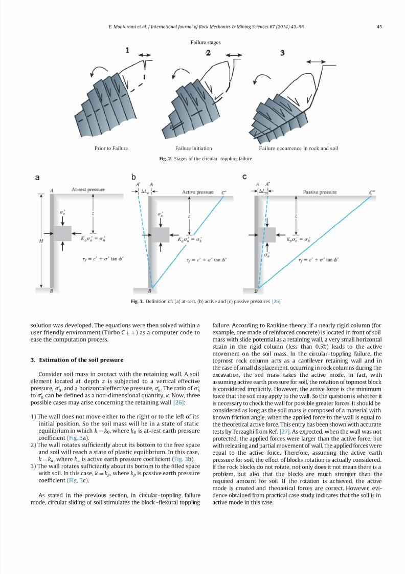
7232019 Slope Stability 201312020
httpslidepdfcomreaderfullslope-stability-201312020 314
solution was developed The equations were then solved within auser friendly environment (Turbo C thorn thorn) as a computer code toease the computation process
3 Estimation of the soil pressure
Consider soil mass in contact with the retaining wall A soilelement located at depth z is subjected to a vertical effectivepressure s0
0 and a horizontal effective pressure s0h The ratio of s0
h
to s00 can be de1047297ned as a non-dimensional quantity k Now three
possible cases may arise concerning the retaining wall [26]
1) The wall does not move either to the right or to the left of itsinitial position So the soil mass will be in a state of staticequilibrium in which k frac14 k0 where k0 is at-rest earth pressurecoef 1047297cient (Fig 3a)
2) The wall rotates suf 1047297ciently about its bottom to the free spaceand soil will reach a state of plastic equilibrium In this casek frac14 ka where ka is active earth pressure coef 1047297cient (Fig 3b)
3) The wall rotates suf 1047297ciently about its bottom to the 1047297lled spacewith soil In this case k frac14 k p where k p is passive earth pressurecoef 1047297cient (Fig 3c)
As stated in the previous section in circularndashtoppling failure
mode circular sliding of soil stimulates the blockndash1047298exural toppling
failure According to Rankine theory if a nearly rigid column (forexample one made of reinforced concrete) is located in front of soilmass with slide potential as a retaining wall a very small horizontalstrain in the rigid column (less than 05) leads to the activemovement on the soil mass In the circularndashtoppling failure thetopmost rock column acts as a cantilever retaining wall and inthe case of small displacement occurring in rock columns during theexcavation the soil mass takes the active mode In fact withassuming active earth pressure for soil the rotation of topmost blockis considered implicitly However the active force is the minimumforce that the soil may apply to the wall So the question is whether it
is necessary to check the wall for possible greater forces It should beconsidered as long as the soil mass is composed of a material withknown friction angle when the applied force to the wall is equal tothe theoretical active force This entry has been shown with accuratetests by Terzaghi from Ref [27] As expected when the wall was notprotected the applied forces were larger than the active force butwith releasing and partial movement of wall the applied forces wereequal to the active force Therefore assuming the active earthpressure for soil the effect of blocks rotation is actually consideredIf the rock blocks do not rotate not only does it not mean there is aproblem but also that the blocks are much stronger than therequired amount for soil If the rotation is achieved the activemode is created and theoretical forces are correct However evi-dence obtained from practical case study indicates that the soil is in
active mode in this case
Failure initiation Failure occurrence in rock and soilPrior to Failure
Failure stages
Fig 2 Stages of the circularndashtoppling failure
Fig 3 De1047297nition of (a) at-rest (b) active and (c) passive pressures [26]
E Mohtarami et al International Journal of Rock Mechanics amp Mining Sciences 67 (2014) 43ndash56 45
7232019 Slope Stability 201312020
httpslidepdfcomreaderfullslope-stability-201312020 414
A shear force is mobilized in the contact surface of the soil withrock column which is controlled by friction angle between soiland wall ethδ THORN and their cohesion (α ) Fig 4a shows outline failurewith the Sokolovski method
Pressure on a rock wall due to the soil mass can be obtainedusing Rankin or Coulombs method Due to overestimation bythese theories in the passive mode Caquot and Kerisel proposedsome tables for obtaining the coef 1047297cient of earth pressure for non-planar surface failure [28] Janbu and later Shields and Toluanyused the slice method for the estimation of soil pressure [2930]Sokolovski presented a 1047297nite difference solution using a mathe-matical method [31] All these methods calculate more realisticvalues for the passive coef 1047297cient of soil pressure But none of them can improve the calculation of active coef 1047297cient pressuresubstantially Rosenfarb and Chen considered various failure
surfaces and combined them with logarithmic layer mechanismTheir 1047297ndings are very consistent with Sokolovskis solutionwhich is widely accepted by other researchers [32] Consideringthe proper velocity component for this mechanism and using thefollowing complement assumptions one can obtain the coef 1047297cientof active earth pressure
1 The soil is idealized as a perfectly plastic material This materialobeys the Coulomb failure criteria and its associated 1047298ow rule
2 In limit analysis states a soil mass will collapse if there is anycompatible pattern of plastic deformation for which the workrate of the external loads exceeds the rate of internal energydissipation due to shearing of the soil [33]
3 Velocity vectors are perpendicular to border line in logarithmic
spiral zone But in active pressure condition a velocity (V 0) isconsidered for the retaining wall with inclination (η) to thehorizontal This angle is usually assumed zero (when theretaining wall is almost vertical) But if the retaining wall isonly toppled in its toe and it is suf 1047297ciently rigid it does nothave the axial strain in this process (commonly) and itsinclination is far from the vertical mode This angle is perpen-dicular to the surface of the retaining wall (it depends on θ which is Deviation angle of the rock column from the vertical)
4 For cohesion less soil only dissipation occurs at the soilndashwallinterface but in cohesion soil this phenomenon also occursdue to shearing
Considering several sectors that divide the failure zone in
which the velocity vector of each sector is the direction at an
angle ϕs to the discontinuous rigid boundary and equating the
rate of the external work to the rate of internal energy dissipationone can obtain a closed form expression for the resultant coef 1047297-cient of active pressure as Eqs (1) to (4) By considering soilfriction angleϕs Eqs (1) and (2) are for non-cohesive soil mass andfor a smooth wall ethδ oφsTHORN and rough wall ethδ frac14 φsTHORN respectively Eqs(3) and (4) are for cohesive soil mass with smooth and rough wallrespectively In Fig 4b soil mass behavior is shown schematically
ksaγ frac14
sec δ cos θ thorn tan δ sin θ frac12 tan δ sin ethθ thorn ρηTHORN= cos ρ
tan ρ cos eth ρthornϕsTHORN sin ethθ thorn ρηTHORN
cos θ cos ϕs
thorn cos 2eth ρthornϕsTHORN
cos ρ cos θ cos 2ϕseth1 thorn9tan 2ϕsTHORN
sin ethθ thorn ρηTHORNfrac123 tan ϕs thorneth sin ξ 3 tan ϕs cos ξ THORNexpeth 3ξ tan ϕsTHORN
thorn cos ethθ thorn ρηTHORNfrac121 eth 3 tan ϕs sin ξ thorn cos ξTHORNexpeth 3ξ t an ϕsTHORN
( )
thorn cos 2eth ρthornϕsTHORN cos ethθ thorn ρηthornξ β THORN sin ethθ thorn ρηthornξTHORNexpeth 3ξ tan ϕ sTHORN
cos ϕs cos θ sin ethθ thorn ρηthornξthornϕs β THORN cos ρ
0BBBBBBBBB
1CCCCCCCCCA
eth1THORN
kr aγ frac14
sec δ cos θ thorn tan δ sin θ
sin 2 ρ cos eth ρthornϕsTHORN sin ethθ thorn ρηTHORN cos ethθ thornϕs THORN
cos 2θ cos ϕs cos eth ρϕsTHORN
cos 2eth ρthornϕsTHORN cos ethθ thornϕs THORN
cos 2θ cos 2ϕseth1 thorn 9tan 2ϕsTHORN cos eth ρϕsTHORN
sin ethθ thorn ρηTHORNfrac123 tan ϕs thorneth sin ξ 3 tan ϕs cos ξ THORNexpeth 3ξ tan ϕsTHORN
thorn cos ethθ thorn ρηTHORNfrac121 eth 3 tan ϕs sin ξ thorn cos ξTHORNexpeth 3ξ t an ϕsTHORN
( )
thorn cos 2eth ρthornϕsTHORN cos ethθ thorn ρηthornξ β THORN sin ethθ thorn ρηthorn ξTHORN cos ethθ thornϕsTHORNexpeth 3ξ tan ϕsTHORN
cos 2θ cos ϕs sin ethθ thorn ρηthornξthornϕs β THORN cos eth ρϕsTHORN
0BBBBBBB
1CCCCCCCA
eth2THORN
ksac frac14
sec δ cos θ thorn tan δ sin θ frac12 tan δ sin ethθ thorn ρηTHORN= cos ρ
tan ρthorn
cos eth ρthornϕsTHORN cos ethθ thorn ρηthornξ β THORNexpeth ξ tan ϕ sTHORN
cos ρ sin ethθ thorn ρηthornξthornϕs β THORN
cos eth ρthornϕsTHORNfrac12expeth 2ξ tan ϕsTHORN 1
sin ϕs cos ρ
eth3THORN
kr ac frac14
sec δ cos θ thorn tan δ sin θ
cos ϕs sin ethθ thorn ρηTHORNcos θ cos eth ρϕsTHORN
thorn sin ρ cos ethθ thornϕs THORNcos θ cos eth ρϕs THORN
thorn
cos eth ρthornϕs THORN cos ethθ thornϕsTHORN cos ethθ thorn ρηthorn ξ β THORNexpeth ξ tan ϕsTHORNcos θ sin ethθ thorn ρηthorn ξthornϕs β THORN cos eth ρϕs THORN
cos eth ρthornϕsTHORN cos ethθ thornϕs THORNfrac12expeth 2ξ tan ϕsTHORN 1
sin ϕs cos θ cos eth ρϕs THORN
8gtgtgtltgtgtgt
9gtgtgt=gtgtgt eth4THORN
where ksaγ and k
r aγ are the active coef 1047297cients of non-cohesive soil
for smooth wall and rough wall respectively ksac and kr
ac are theactive coef 1047297cients of cohesive soil for smooth wall and rough wall
respectively We show these four variables with ka Parameters δ θ
ρ
δ
ψ
ξ
β
φ
φθη
φ
δστ =
Fig 4 (a) The slip lines and the failure area based on Sokolovski method [31] and (b) plastic stress areas for the active soil pressure mode using the theory of plasticity
E Mohtarami et al International Journal of Rock Mechanics amp Mining Sciences 67 (2014) 43ndash56 46
7232019 Slope Stability 201312020
httpslidepdfcomreaderfullslope-stability-201312020 514
β η ϕs ρ and ξ represent the friction angle between soil and rockmass deviation angle of rock column from the vertical inclinationof soil surface inclination of velocity vector of the retaining wall
the internal soil friction angle the angle between the lower boundof soil plastic zone and the upper bound of the last block Theangle between the lower and the upper bound of soil plastic zoneis shown in Fig4
To calculate the force on the topmost rock column the activecoef 1047297cient of soil mass must be 1047297rst calculated according to realconditions (one of the above four states) Eqs (1)ndash(4) should besolved for the maximum amount of ka Determination of the
maximum amount of ka depends on two variables ρ and ξ If β frac14 δ frac14 0 the results of the proposed equations are the same asRankine and Coulombs methods However this solution givesmore accurate results when the soil friction angle ethφsTHORN is greaterthan 351 and δ is about ϕ=2 or more and β a0 comparing toRankine and Coulombs methods
To evaluate the accuracy in the results of the proposed methodthey are compared with the results of 1047297nite element method andCoulomb methods (Table 1) By changing the angle of the retainingwall and soil friction angle a stress is obtained which acts on thewall in a certain depth in three methods Fig 5andashc shows thegeometry of the constructed models in Plaxis 3D Tunnel [34] If thenumerical answers are considered accurate the errors presentedin Table 1 belong to Coulomb and the proposed method ascompared to the numerical method It can be seen that the errorof Coulombs method increases with reducing the angle of theretaining wall Instead the error of the proposed theory remains inthe acceptable range
When the active coef 1047297cient of the soil mass ethkaTHORN is calculatedfrom one of above equations the force on the topmost rock
Table 1
Comparison of Coulomb and proposed methods results with numerical method
θ
(degree)ϕs
(degree)Depth(m)
FEM(KNm 2)
Coulomb(KNm 2)
Error of Coulomb()
Offeredtheory(KNm 2)
Error of offeredtheory()
0 20 6687 59881 57030 0048 59762 000240 6708 37265 27201 0270 36184 0029
5 20 6715 83122 78417 0057 81459 002040 6715 39610 36847 0070 38818 0020
10 20 6881 88358 82965 0061 89242 001040 6881 41842 38671 0076 41340 0012
15 20 6618 87411 81693 0065 85838 001840 6618 41591 38122 0083 40510 0026
20 20 6473 88573 82164 0072 86713 002140 6473 42098 38305 0090 40961 0027
25 20 6705 95639 87985 0080 94109 001640 6705 4 5196 40571 0102 44473 0016
30 20 6386 94705 86489 0087 92432 002440 6386 4 5187 39989 0115 43741 0032
35 20 6652 103092 93296 0095 100721 002340 6652 4 9460 42638 0138 48125 0027
40 20 6587 107245 96011 0105 104992 002140 6601 52522 43769 0167 50947 0030
(KNm 2)
0000
-10000
10000
-20000
-30000
-40000
-50000
-60000
-70000
-80000
-90000
-100000
-110000
-120000
Fig 5 (a) Displacement of soil and wall with θ frac14251 and ϕfrac14201 (b) displacement of soil and wall with θ frac14251 and ϕfrac14401 and (c) stress distribution and deformation in
model with ϕfrac14401 and ϕfrac14201
E Mohtarami et al International Journal of Rock Mechanics amp Mining Sciences 67 (2014) 43ndash56 47
7232019 Slope Stability 201312020
httpslidepdfcomreaderfullslope-stability-201312020 614
column of slope can be obtained by Eq (5)
pa frac1412
kaγ sh2
thornkaqqh eth5THORN
In this equation (q) is the overhead pressure in the soil part(see Fig 6b) (h) is the depth of soil at the desired point andkaq frac14 ka= cos eth β θ THORN which is known by Parandtl equilibriumcoef 1047297cient ka can be obtained from Eqs (1)ndash(4) If the soil iscohesive two forces act on the rock column a friction force withangle (δ ) and the normal vector to rock column with the amount(E ) which is de1047297ned by Eq (6) The other force is the result of cohesion between soil and rock (α ) [32]
E frac14 s
cos δ frac14 kaγ sh thorn kaqq kac c eth6THORN
in which
kac frac141= cos δ kaq
tan ϕs
eth7THORN
and γ s and c are the unit weights of the soil mass and soil cohesiverespectively
In a soil mass with cohesion there might be an area thatexperiences the tensile stress The existence of the tensile stressesin the upper body leads to the cracks and 1047297ssures in the soil massand also separation of the soil from the rock columns at lengthL0(Fig 6b) This part of soil has no direct effect on rock columnhowever its total effect is considered as a uniform load on the topof soil mass which is shown as ldquoqrdquo in Eqs (5) and (6) The length of tensile crack can be determined by setting ldquoE rdquo in Eq (6) equal tozero shown as Eq (8) [32]
L0 frac14kac c kaqq
kaγ seth8THORN
Therefore according to Fig 6a the active slide of a cohesive mass
is equal to the sum of two forces
A force with inclination equal to δ has a value of kaγ sethL L0THORN2=2acting on a lower third line segment A 0B
Surface cohesion along the contact surface with the value of aethL L0THORN
4 Stability analysis of rock slope subject to
secondary toppling failure
Discontinuities in rock often happen in an irregular mannerHence the pure toppling failure (1047298exural and blocky) is very rareand most failures occurring in nature are of blockndash1047298exural type [2] Asingle column subject to secondary blockndash1047298exural toppling is stati-cally inde1047297nite however by considering several assumptions one
can obtain an appropriate theoretical solution to calculate columninteraction forces The following simplifying assumptions for theblockndash1047298exural toppling in the present analysis have been used
Force applied by a solid rock column is the same as a columnformed by several blocks [218]
All columns in a rock mass with the potential of blockndash1047298exuraltoppling have equal safety factor equal to the safety factor forwhole slope
The basal failure plane is emanated from the toe of the slopeand oriented at an angle 10ndash201 upward from the normal tothe main discontinuities [23]
For more details related to the second condition it should besaid that in a system with various components safety factor of each component is determined by its stability But the purpose of the limit equilibrium method is the stability of the whole struc-ture In other words this method calculates the distance betweenthe present state of structure and the failure mode In rock slopesby considering the type of components and applied forces to eachcolumn or block different safety factors can be taken The 1047297nalpurpose of analysis is the stability of the whole slope for whichthe second assumption will help us Two types of columns in theblockndash1047298exural toppling mechanism can be distinguished
a) Columns with discontinuities in their base (we call themblocks) These blocks might be stable or unstable under oneof the following modes (a) sliding (b) toppling (c) slidingndash
toppling and (d) topplingndashsliding In any of the above instabil-ity modes a block will impose a certain force to the next block
b) Columns anchored to the base rock act as a cantilever beamForce applied by upper columns on a certain column as wellas its weight mobilizes a tensile stress in rock at the columnbase The column may break if this stress exceeds rock tensile
L
0 L L minus
A
3
0 L L minus
A
B
)( 0 L La minus
2
)(
20 L L
k minus
γ γ
δ
0 L
Fig 6 (a) Applied forces on the topmost column and (b) tensile cracks within a cohesive mass
E Mohtarami et al International Journal of Rock Mechanics amp Mining Sciences 67 (2014) 43ndash56 48
7232019 Slope Stability 201312020
httpslidepdfcomreaderfullslope-stability-201312020 714
strength The column may also break under shear forces whichhappen if the applied loads mobilize enough shear stress onrock at column base to overcome rock shear strength
In this paper blocks and columns are generally called columnwherever their type is not important but when their type isimportant in calculation process we will call them column orblock depending on whether they are connected or not connectedat their base respectively So the blockndash1047298exural toppling is thecombination of four modes of blocky toppling sliding 1047298exuraltoppling and shearing in the rock columns
Fig 7 shows a theoretical model for the circularndashtopplingfailure In this section an analysis method is introduced for allfour modes of blockndash1047298exural toppling In this analysis any columnwithin the slope under study (say ith column) may potentially failin 1047298exural toppling or blocky toppling mode The following casesare considered in the analysis
41 Blocky toppling failure mode
Block ldquoirdquo which is presumably subject to blocky toppling iseither stable or fails in the state of toppling sliding topplingndashsliding
or slidingndash
toppling Thus these four states of instability should beconsidered in the analysis The topmost block (adjacent to the soilmass) may similarly have one of these 1047297ve states however it isunder applied pressure by soil at one side which is calculated byEq (5) Limit equilibrium for the 1047297ve states are as follows
a) Pure toppling failure mode In this mode the block ldquoirdquo is notsliding but is subject to toppling The equilibrium state can beshown as follows (Fig 8a)
sum f x frac14 ma x sum f y frac14 ma y S ioN i tan ϕ p
T i 1 ffi pi 1 tan ϕd T i thorn 1 ffi pi thorn 1 tan ϕd Li frac14 minethhi hi 1THORN
(
eth9THORN
where f x is force along the ldquo xrdquo f y is force along the ldquo yrdquo m is
rock column mass a x is acceleration components along ldquo xrdquo a y
is acceleration components along ldquo yrdquo pi thorn 1 is normal force appliedby column ldquoithorn1rdquo on column ldquoirdquo pi 1 is normal force appliedby column ldquoi1rdquo on column ldquoirdquo T i thorn 1 is shear force applied bycolumn ldquoithorn1rdquo on column ldquoirdquo T i 1 is shear force applied bycolumn ldquoi-1rdquo on column ldquoirdquo N is the normal force at the base of column S is the shear force at the base of column ϕ p is frictionangle between block and underneath rock ϕd is friction anglealong the column interfaces Li is distance between pi 1 andfailure plane (see Fig 8) and hi is height of column i
By substituting all the forces in the above dynamic equilibriumequations for intermediate blocks (i frac14 1 to i frac14 n1) and topmostblock ethi frac14 nTHORN in directions of ldquo xrdquo and ldquo yrdquo and rotational dynamicequilibrium it can be rewritten as followsFor intermediate blocks (IB) or 8 i A IB
aTHORN w i
g ai
x frac14 wi sin ψ thorn pi thorn 1 thorn V thorni pi 1 V i S i thornc ewi cos β e
bTHORN w i
g ai
y frac14 wi cos ψ thorn T i thorn 1 T i 1 N i V i c ewi sin β e
cTHORN w i
g
t 2i thorn h
2i
3 aiθ frac14 wi sin ψ hi
2 thorn c ewi cos β ehi
2 thorn N iei
thorn pi thorn 1M i pi 1Li thornV thorn
i yi
3 T i thorn 1t i V i z i
3
ethwi cos ψ c ewi sin β eTHORNt i2 thorn
γ wt 2i
6 cos ψ eth z i thorn2 yiTHORN
8gtgtgtgtgtgtgtgtgtgtltgtgtgtgtgtgtgtgtgtgt
eth10THORN
For topmost block (TB) or 8 i A
TBaTHORN w i
g ai
x frac14 wi sin ψ thorn pns thorn V thorni pi 1 V i S i thorn c ewi cos β e
bTHORN w i
g ai
y frac14 wi cos ψ thorn pns tan δ thorn ps
s thorn pc s T i 1 N i V i c ewi sin β e
cTHORN w i
g
t 2i thorn h2
i
3 aiθ frac14 wi sin ψ hi
2 thorn c ewi cos β ehi
2 thorn N iei thorn pns M i
pi 1Li thornV thorn
i yi
3 ethwi cos ψ c ewi sin β eTHORNt i2
eth pss thorn pc
s thorn pns tan δ THORNt i
V i z i3 thorn
γ wt 2i
6 cos ψ eth z i thorn2 yiTHORN
8gtgtgtgtgtgtgtgtgtgtltgtgtgtgtgtgtgtgtgtgt
eth11THORN
where pns is vertical component of load applied by soil on rock
mass pss is tangential component of load applied by soil on rock
mass pc s is shear force on contact plane of soil and topmost
column wi is weight of column I g is acceleration of gravity a x is
component of acceleration acting on column ldquoirdquo
along the X axis
β
H
sψ
1 K
Ωα
iM
p1minusi
bt
t f
i
i - 1
L i
i - 1
iiT 1+
p1+i
i
11
minusminusiiT
1minusi
i
Fig 7 Model for investigating blockyndash1047298exural toppling failure when blocks with potential of blocky and 1047298exural toppling located the alternating binary consecutive
E Mohtarami et al International Journal of Rock Mechanics amp Mining Sciences 67 (2014) 43ndash56 49
7232019 Slope Stability 201312020
httpslidepdfcomreaderfullslope-stability-201312020 814
a y is component of acceleration acting on column ldquoirdquo along the Y
axis ai
θ angular acceleration acting on column i γ
w is unit weight
of the water yi is water level in the upstream (US) of ith column z i is water level in the downstream (DS) of ith column V thorni iswater pressure at US V
i is water pressure at DS V i is uniformwater pressure at base t i is thickness of ith rock columnregardless of its type (t b and t f for blocky and 1047298exural modesrespectively) ei is distance of applying load point at the base of column ldquoirdquo to its lower edge M i is distance between pi thorn 1 andfailure plane (see Fig 8) ψ is inclination of block base plane c e isseismic coef 1047297cient and β e is deviation angle of the seismic forcefrom the X axisConsidering ai
x frac14 ai y frac14 0 and e frac14 0 for Eqs (10a) (10b) (11a) and
(11b) and solving them for pt i 1 ie the required force for
preventing failure of block ldquoirdquo lead to the following 1047297nal results
pt i 1 frac14 pi thorn 1M i pi thorn 1
tan ϕd
F s t b thorn wi sin ψ hi
2 wi cos ψ t b
2 thorn c ewi cos β e
thorn c ewi sin β e thornV thorn
i yi
3 thornγ wt 2
b
6 cos ψ eth z i thorn2 yiTHORN V i z i
3
24 35
L 1i 8 iAIB eth12aTHORN
pt i 1 frac14
wieth sin ψ thornc e cos β eTHORNhi
2 wieth cos ψ c e sin β eTHORNt b2 thorn pn
s M i pns
tan δ F s
t b
eth pss thorn pc
s THORNt b thornV thorn
i yi
3 thornγ wt 2
b6 cos ψ eth z i thorn2 yiTHORN V i
z i3
24
35
L 1i 8 iATB eth12bTHORN
where F s is factor of safety pss and pn
s are projections of active soilforce parallel and perpendicular to block respectively pc
s is theshear force along the block contact plane Fig 9 shows theseforces clearly M i measures the distance from the failure plane tothe point of acting pi 1 The force pi 1 is applied at the middle of
block ldquoithorn1rdquo
if the block ldquoithorn1rdquo
is sliding shearing or slidingndash
toppling (Fig 10a) If the block ldquoithorn1rdquo fails in pure toppling1047298exural toppling and topplingndashsliding the position of application of force ldquo pi thorn 1rdquo can be given in a general form as inEq (13) [21]
M i frac14 λhi eth13THORN
Laboratory model tests employed by Aydan et al show that thevalue of λ should be 075 to 1 [21] According to results of theirstudies it is advisable to assume λ frac14 1 which is obviously aconservative approach and is considered in this paper(Fig 10b) pi thorn 1 acts on one third of block height from the bottomto the topmost block as soil pressure
b) Sliding failure mode In this mode ith block has only slidingpotential without blocky toppling potential Equilibrium equa-tions and some simplifying assumptions can be as follows
T i thorn 1 ffi pi thorn 1 tan ϕd e frac14 t b=2
T i 1 ffi pi 1 tan ϕd Li frac14 hi=2
S i frac14 N i tan ϕ p a x frac14 a y frac14 0
8gtlt
gteth14THORN
By considering Eqs (10) and (11) and solving equilibriumequations ps
i 1 can be calculated as follows
psi 1 frac14 pi thorn 1 thorn wi eth cos ψ c e sin β eTHORN
tan ϕ p
F s sin ψ c e cos β e
h inthornV thorni thornV i
tan ϕ p
F sV i
o 1
tan ϕ p
F stan ϕd
1
8 iAIB
eth15aTHORN
psi 1 frac14
wi sin ψ cos ψ tan ϕ p
F sthorn c e cos β e thorn sin β e
tan ϕ p
F s
h ithorn pn
s 1 tan δ tan ϕ p
F s
eth ps
s thorn pc s THORN
tan ϕ p
F sthornV thorni thorn V i
tan ϕ p
F sV i
8gtltgt
9gt=gt
1 tan ϕ p
F stan ϕd
1
8 iATB eth15bTHORN
1+i
piminus1
1+iT
1minusiT a i M
L a i
p1+i
p1minusi
1+iT
1minusiT a i M
L a i
i
i
t b t f
βegt 0
βelt 0
Fig 8 (a) Force on a single block with potential of blocky toppling failure and (b) force on a column with the potential of 1047298exural toppling failure
p s
n
c p s
s p s
total psoil
Fig 9 Forces act on the topmost rock column due to active landslide of soil mass
E Mohtarami et al International Journal of Rock Mechanics amp Mining Sciences 67 (2014) 43ndash56 50
7232019 Slope Stability 201312020
httpslidepdfcomreaderfullslope-stability-201312020 914
If pt i 1 and ps
i 1 are both positive for a block which showsinstability the block should be further examined for possibletopplingndashsliding and slidingndashtoppling failure These two statesare explained in the next sections
c) Toppling ndashsliding failure mode If pi 1 t 40 pi 1 s40 and pi 1 t 4 pi 1 t the failure happens in topplingndashsliding modeBy solving Eqs(10) and (11) and using assumptions in (16) pts
i 1 it can be calculated for intermediate blocks and thetopmost one as follows
S i frac14 N i tan ϕ p T i thorn 1 ffi pi thorn 1 tan ϕd T i 1 ffi pi 1 tan ϕd
ei frac14 0 ai x frac14 ai
θ hi
2 ai y frac14 ai
θ t b2 ai
θ Z0
(
eth16THORN
ptsi 1 frac14
1k
wifrac12eth sin ψ thorn c e cos β eTHORNeth4t 2b thornh2i 3hit b tan ϕ pTHORN
thorn eth cos ψ thornc e sin β eTHORNeth tan ϕ peth4h2i thornt 2bTHORN 3hit bTHORN
thorn1k pi thorn 1
eth4t 2b thorn4h
2i 6M ihi 6M it b tan ϕ pTHORN
thorn tan ϕd
F seth tan ϕ peth2t 2b 4h
2i THORN thorn6hit bTHORN
thorn1k
h2i 4ethV thorni V i thornV i tan ϕ pTHORN
2hi
ethV thorni yi V i z iTHORN
thorn1k
t 2b 4ethV thorni V i thornV i tan ϕ pTHORN
2 tan ϕ p
t bethV thorni yi V i z iTHORN
γ w cos ψ eth z i thorn2 yiTHORNetht b tan ϕ p thorn hiTHORN
8 iAIB eth17aTHORN
ptsi 1 frac14
1k
wi eth sin ψ thornc e cos β eTHORNeth4t 2b thorn h2i 3hit b tan ϕ pTHORN
hthorn eth cos ψ thornc e sin β eTHORNeth tan ϕ peth4h
2i thornt 2bTHORN 3hit bTHORN
ithorn
1k pn
s 4t 2b thorn4h2i thorn
tan δ
F seth tan ϕ peth2t 2b 4h
2i THORN thorn6t bhiTHORN
6M iethhi thorn t b tan ϕ pTHORN
thorn1
k
eth pss thorn pc
s THORN 6t betht b tan ϕ p thornhiTHORN 4 tan ϕ pethh2i thornt 2bTHORNh i
thorn1k
t 2b 4ethV thorni V i thornV i tan ϕ pTHORN 2 tan ϕ p
t bethV thorn
i yw V i z wTHORN
γ w cos ψ eth z w thorn2 ywTHORNetht b tan ϕ p thorn hiTHORN
thorn1k
h2i 4ethV thorni V i thorn V i tan ϕ pTHORN
2hi
ethV thorni yw V i z wTHORN
8 iATB
eth17bTHORNwhere k is
k frac14 eth4etht 2b thorn h2i THORN 6LihiTHORN tan ϕ peth6Lit b thorn4
tan ϕd
F setht 2b thornh
2i THORNTHORN
Similar to the previous cases M i and Li depend on the type of failure of the two blocks the block under examination ldquoirdquo andthe upper block ldquoithorn1rdquo Finally after calculating p ts
i 1 we mayhave one of the following states
ptsi 1o 0 Pure toppling
ptsi 1 0 Transfer from toppling mode to combined mode
ptsi 14 0 TopplingSliding
8gtltgt
d) Sliding ndashtoppling failure mode If pt i 1 and ps
i 1 are bothpositive and p t
i 1 o psi 1 the failure happens in sliding-toppling
mode By considering the dynamic equilibrium equations in (10)and (11) and using assumptions in (18) pst
i 1 can be calculated forintermediate blocks and the topmost block as follows
S i frac14 N i tan ϕ p T i thorn 1 ffi pi thorn 1 tan ϕd T i 1 ffi pi 1 tan ϕd
ei frac14 0 ai xZ0 ai
y frac14 0 aiθ frac14 0
8lt eth18THORN
pst i 1 frac14
pi thorn 1tan ϕ p
F stan ϕd 1
hi
2 t b tan ϕd thornM i
h ithorn wi cos ψ
tan ϕ p
F shi
2 t b2
thorn c e sin β e
t b2 hi
2tan ϕ p
F s
h i hi
2 V thorni thorn V itan ϕ p
F s V i
h ithorn
V thorni yi
3 V i z i
3 thornγ wt 2
b
6 cos ψ eth z i thorn2 yiTHORN
8gtgtgtgtgtltgtgtgtgtgt
9gtgtgtgtgt=gtgtgtgtgt
8 iAIB Li 1tan ϕ p
F stan ϕd
hi
2 1
eth19aTHORN
i M
p i +
1
a i M
p i + 1
i i
i + 1 i + 1
Fig10 Position of application of the normal force on block ldquo irdquo from the upper block when the upper block is (a) pure sliding shearing slidingndashtoppling type and (b) puretoppling topplingndashsliding type
E Mohtarami et al International Journal of Rock Mechanics amp Mining Sciences 67 (2014) 43ndash56 51
7232019 Slope Stability 201312020
httpslidepdfcomreaderfullslope-stability-201312020 1014
pst i 1 frac14
pns
tan ϕ p
F stan δ 1
hi
2 t b tan δ thorn M i
h ithornwi cos ψ
tan ϕ p
F s
hi
2 t b2
thornc e sin β e
t b2 hi
2tan ϕ p
F s
h i hi
2 eth pss thorn pc
s THORN tan ϕ p V thorni V itan ϕ p
F sthorn V i
h i
eth pss thorn pc s THORNt b thornV thorn
i
yi
3 V
i
z i3 thorn
γ w t 2
b6 cos ψ eth z i thorn2 yiTHORN
8gtgtgtgtgtgtgtgtlt
gtgtgtgtgtgtgtgt
9gtgtgtgtgtgtgtgt=
gtgtgtgtgtgtgtgt Li 1
tan ϕ p
F stan ϕd
hi
2
1
8 iATB eth19bTHORN
In this case M i and Li are determined as in the previous casesStability determination or the type of possible instability in thecalculated block is done as follows
pst i 1 0 Only sliding
pst i 1 0 Transfer from sliding mode to the slidingtoppling
pst i 14 0 SlidingToppling
8gtltgt
e) Stable mode When psi 1 pt
i 1 o 0 the block is stable In this
case there is no need to calculate ptsi 1 and p
st i 1 Also pi 1 is
assumed to be zero in the subsequent calculation for other blocksIf this condition happens for the topmost block the soil mass hasno effect on the blocks system In this case the secondary topplingis not a probable mode of failure However any other topplingmode may still happen
42 Flexural toppling mode
If block ldquoirdquo is connected to the rock at the base of the slopeforming a cantilever position (Fig 8b) it shows tensile strengthdue to the bending state of loading Three modes ie 1047298exuraltoppling shearing and stable state can be expected
a) Flexural toppling mode In this mode column ldquoirdquo may fail dueto bending moment acting on the column Equilibrium equa-tions used in the previous section (Eqs (10) and (11))
can be used to analyze this state of loading The following
Is it first stagen = 0
Start
input parameters
NoYes
R e d u e F
s
u s i n g a r t i f i c i a l
b e e c o l o n y
Calculation of columnrsquos
data amp optimization of k a
F s = 1
Calculate of p i (i=0-n )
Display F s as an output
End
I n c r e a s e F
s
u s i n g a r t i f i c i a l
b e e c o l o n y
n = n+1n = n+1
Refer to algorithm shown in figure 12
Fig 11 A schematic algorithm of the computer codes process
Table 2
Input parameters which are used in the developed software
Input parameters Unit Input parameters Unit
Height of slope m Inclination of soil surface degreeAverage thickness of the layers in blocky mode m Friction angle between soil and rock mass degreeAverage thickness of the layers in 1047298exural mode m Internal soil friction angle degree
Distance between the soil mass to rock slopersquos crest m Cohesive in soil mass KNm
3
Slope angle with the horizontal degree Surface cohesive between the soil mass and rock KNm 3
Inclination of top surface of slope degree Friction angle of intact rock degreeInclination of the layers degree Tensile strength of rock mass KNm 3
Inclination of the failure plane degree Cohesive of intact rock sample KNm 3
Inclination of block base plane degree Pseudo-static seismic force coef 1047297cient ndash
Friction angle between block and underneath rock degree Deviation angle of the seismic force from x axis degreeFriction angle along the block interface degree
E Mohtarami et al International Journal of Rock Mechanics amp Mining Sciences 67 (2014) 43ndash56 52
7232019 Slope Stability 201312020
httpslidepdfcomreaderfullslope-stability-201312020 1114
assumptions are applicable
T i thorn 1 frac14 pi thorn 1 tan ϕd
T i 1 frac14 pi 1 tan ϕd
ei frac14 t f =2
ai x frac14 ai y frac14 0
8gtgtgtgtltgtgtgtgt
eth20THORN
Bending moment (M ) and axial force (N ) on the column at thebase point of the column are obtained as follows
N i frac14 wi cos ψ thornT i thorn 1 T i 1 V i c ewi sin β e eth21THORN
M frac14 wieth sin ψ thorn c e cos β eTHORNhi
2thorn pi thorn 1M i thorn
V thorni yi
3
t f
2ethT i thorn 1 thorn T i 1THORN
pi 1Li V
i z i3
V iLout eth22THORN
where Lout is the eccentric water pressure at base The total stressin the column should be calculated from both ldquoM rdquo and ldquoN rdquo as
shown in Eq (23) If the total tensile stress in rock column exceeds
the tensile rock strength st the rock breaks and the column isoverturned In equilibrium conditions the tensile stress mentionedin Eq (23) is equal to the tensile strength of rock It may berewritten as Eq (24) and safety factor of rock column against thetensile stress and hence against toppling is obtained from Eq (25)
s y frac14 t f =2t frac14
Mt f
2I i
N it f
eth23THORN
M frac142I it f
st thornN it f
eth24THORN
F s frac14 st =st f =2
y eth25THORN
By substituting ldquoM rdquo and ldquoN rdquo from Eqs (21) and (22) in Eq (24) p f t
i 1 is obtained as shown in Eq (26a) for the intermediatecolumns (IC) and in Eq (26b) for the topmost column (TC columnadjacent to soil mass) where I i is the second moment of columnldquoirdquo Similar to the previous cases Li and M i depend on failure type
of column or block ldquoirdquo
and ldquoithorn 1rdquo respectively
Block is
connected at its
bottom
Start
Initial calculations
NoYes
No
Yes No
Yes
No
Yes
Yes
No
Input parameters
Calculate of amp Calculate of amp
Calculate of Calculate of
Display output ie
and failure mode
End
Fig 12 An algorithm for calculating the ldquo pi1rdquofor column ldquoirdquo
Fig 13 (a) Overview of the slope and the Haraz road and (b) the soil part on top of the slope and partially equilibrium
E Mohtarami et al International Journal of Rock Mechanics amp Mining Sciences 67 (2014) 43ndash56 53
7232019 Slope Stability 201312020
httpslidepdfcomreaderfullslope-stability-201312020 1214
p f t i 1 frac14
pi thorn 1ethM i tan ϕdt f 2
2 tan ϕdI it 2 f
THORN
thornwihi
2 eth sin ψ thornc e cos β eTHORN thorn V iLout thornV thorni yi
3 thornV i z i
3
h i2I i
t f st
F sthorn
wi eth cos ψ c e sin β eTHORN V it f
8gtgtgtgtgtltgtgtgtgtgt
9gtgtgtgtgt=gtgtgtgtgt
tan ϕd
t f
2thornLi
2 tan ϕdI i
t 2 f
1
8 iAIC eth26aTHORN
p f t i 1 frac14
pns ethM i tan δ
t f 2THORN thornwi
hi
2 eth sin ψ thornc e cos β eTHORN
thorn V iLout thornV thorni yi
3 thornV i z i
3
h ieth ps
s thorn pc s THORN
t f 2
2I it f
st
F sthorn
wieth cos ψ c e sin β e THORN thorn pss thorn pc
s V it f
8gtgtgtgtltgtgtgtgt
9gtgtgtgt=gtgtgtgt
eth tan ϕd
t f
2thorn LiTHORN
1 8 iATC eth26bTHORN
b) Shear failure mode In this mode column ldquoirdquo may fail undershear force perpendicular to column axis The force shouldobviously overcome rock shear resistance mobilized by cohe-sive (C ) and friction (φr ) in intact rock By consideringassumptions in Eq (27) and limit equilibrium equations value
of pshi 1 for intermediate and topmost column it is obtained
from Eqs (28a) and (28b) respectively
T i thorn 1 ffi pi thorn 1 tan ϕd ei frac14 t f =2 ai x frac14 ai
y frac14 0
T i 1 ffi pi 1 tan ϕd S i frac14 N i tan ϕr thorn Ct f
(
eth27THORN
pshi 1 frac14 pi thorn 1 thorn wi eth cos ψ c e sin β eTHORN
tan ϕr
F s sin ψ c e cos β e
thorn V thorni thorn V itan ϕr
F s V i Ct f
) 8 iA IC 1
tan ϕr
F stan ϕd
1
eth28aTHORN
pshi 1 frac14 pn
s eth1 tan δ tan ϕr
F sTHORN wi eth cos ψ c e sin β eTHORN
tan ϕr
F s
sin ψ c e cos β e
8 iATC
eth pss thorn pc
s THORNtan ϕr
F sthorn V thorni thornV i
tan ϕr
F sV i Ct f
)
1 tan ϕr
F stan ϕd
1
eth28bTHORN
c) Stable mode When p f t i 1 psh
i 1r0 the column is stable and pi 1 is assumed to be zero in the subsequent calculation forother columns or blocks
5 Computer code developed for stability analysis
In the previous section a complete solution for circularndashtop-pling failure was presented To assess the overall stability of aslope with the combination of soil mass and rock columns thealgorithm shown in Fig 11 is proposed A computer code wasdeveloped using a user friend environment This algorithm wasused for slop stability evaluation and the calculation of safetyfactor Table 2 shows the input parameters The output for theintermediate stage of calculations is the forces between thecolumns ie pi 1 and pi thorn 1 for each column The 1047297nal output isthe force required to support toe column p0 and the safety factorof slope In this algorithm the coef 1047297cient of lateral earth pressurein the active mode ka is calculated using Eqs (1) to (4) for varioussoil conditions ldquoArti1047297cial bee colony optimizationrdquo algorithm wasused to optimize ka value Having found ka we calculated pi thorn 1 forthe topmost column using Eq (5) The values of pi 1 and pi thorn 1 iethe forces applied at both sides of each column are then calculatedaccording to the algorithm shown in Fig 12 and the formulationsdescribed in the previous section
53
25
45
6 7 0 m
3 1 9
2 m
77
Soil mass
Fig 14 A schematicof the slope located in Haraz
Table 3
Conducted tests in soil and rock parts
Conducted tests in rock parts Conducted tests in soil part
Test name Description Test name Description
Direct shear tests ϕfrac1428661 c jfrac14008 MPa Direct shear tests (using normal stress 5 Kgcm3) c frac14819 KNm 2 ϕfrac1427581Non-encapsulated strain s
avec frac14 14951 MPa Non-encapsulated strain sc frac142843 Kgcm 3
Dry and saturation density (Kgcm 3) γ dry frac14 262 γ sat frac14 2677 Determinat ion of speci1047297c gravity GS frac14259
Chemical testing of groundwater Water is not acidic or alkaline Chemical testing of groundwater Water is not acidic or alkalinePetrographic characteristics (dominant mineral) Quartz potassic feldspar biotite Dry and saturation density (Kgcm 3) γ dry frac14 1577 γ sat frac14 1968
Porosity and saturation percent n frac14 516 s frac14 2578 Porosity and saturation percent n frac14 391 s frac14 70Determination E and υ (21 samples) υ frac14 0239 E frac14 1607 ethGPaTHORN Determination E and υ υ frac14 036 E frac14 1250 ethKg =cm2THORN
The ultrasonic wave velocity V com frac14 3220 V sh frac14 1853 ethm=sTHORN The ultrasonic wave velocity V com frac14 1155 V sh frac14 540 ethm=sTHORN
E Mohtarami et al International Journal of Rock Mechanics amp Mining Sciences 67 (2014) 43ndash56 54
7232019 Slope Stability 201312020
httpslidepdfcomreaderfullslope-stability-201312020 1314
By 1047297nding p0 (ie p i 1 for toe column) the stability of a slopesubject to circular-toppling failure can be judged as follows
p04 0 Unstable
p0 frac14 0 Limit equilibrium condition
p0o 0 Stable
8gtlt
gt It should be noted that safety factor ethF sTHORN is set equal to 1 for
1047297nding p0 at the initial stage If p0 frac14 0 at the initial calculations theslope is at equilibrium state and calculation is no longer necessaryIf p040 then the slope is unstable and the value of F s is reducedgradually until p0 frac14 0 The 1047297nal calculated F s is the actual safetyfactor of the slope Similarly if p0o0 then the slope is stable Theactual safety factor is found by increasing the amount of F s incalculation loop till p0 frac14 0 The 1047297nal calculated F s is the actualsafety factor of the slope The increase or reduction of F s anddetermination of the optimum value are done using the arti1047297cialbee colony algorithm (Fig 11) In the previous studies the blockshave been alternately considered in blocky or 1047298exural topplingmode The proposed solution in this paper freely allows for anycombination
6 Case study
A real case including a slope subject to failure was studiedusing the proposed method This slope is located in Vana villagealong Haraz road in northern Iran 70 km from Amol city Theslope consists of rhyolite tuff overlooking Haraz road with thepotential of toppling Fig 13 shows the general view of the slopeand Fig 14 depicts the slope schematically As can be seen in these1047297gures a large amount of sediments and volcanic debris isdumped on the top of slope behind the rock columns This massgenerates the soil active pressure Ongoing erosion of the sedi-ments and volcanic rock not only increases the active pressure butalso causes the rock falls which have already caused some
accidents and injuries Due to the concern of possible failure of block rocks a research project was organized by research instituteof the Ministry of Roads and Urban Development for the evalua-tion of the general stability of the slope The existing residentialand commercial buildings next to this slope helped authoritiesaccept the minimum F S to be equal to 155
A number of exploration drillings were performed within theslope to obtain the geo-mechanical properties Moreover observa-tions were made through the existing tunnel of an old coal mine inthe area Table 3 shows the main obtained data used for this study
The stability of the slope in Vana village was analyzed using theproposed method and the developed code The code shows severalitems as outputs (a) Geometry and geo-mechanical parameterswhich are partially inputted by the user and partially calculated
by the code (b) forces between the columns ( pi1 and p ithorn1) and
possible failure mode of each block and (c) safety factor andstability state of the slope Furthermore we can obtain the appliedforce on topmost block by the soil by running the computer code
The analysis revealed that safety factor for this slope was equalto 164 for combined circularndashtoppling failure which was higherthan the acceptable 1047297gure by authorities The slope was found atstable state however it should be noted that due to futureerosions soil value and active soil pressure may increase during
the years Thus update evaluation may be necessary from time totime Moreover despite the general stability of this slope localrock falls can still happen Fig 15 shows potential rock falls due toerosion resulted by the running water
7 Conclusions
Different types of the toppling failure are still a major instabil-ity for slopes in nature and slopes all over the world Combinedcircularndashtoppling failure is a kind of instability not studied beforein details In this paper a complete solution was presented for thistype of failure A new formulation was developed to investigatethe stability of slope components (the soil and rock part)
The developed solution in this paper has taken all the effectiveparameters (external forces water pressure and earthquake) intoaccount Every column can be in any mode of failure including astable mode The presented solution unstable forms were widelyanalyzed from the point of limit equilibrium method in discontin-uous rock and allowed for any combination of failure in thecolumns ie failure mode of each column could be different withthe mode of neighboring columns Another advantage of theproposed solution is that the topmost column can have anyinclination and the applied force by soil mass can be calculatedby plasticity theory which has good accuracy
A computer code was developed to ease the use of the proposedsolution The code was simple and fast it gave the 1047297nal state of stability as well as safety factor of the slope By using this code the
effect of different parameters (like block inclination friction etc) onstability can be simply and quickly studied Such a study can helpthe users decide on the necessary measures for making the slopemore stable
References
[1] Goodman RE Bray JW Toppling of rock slopes In Boulder CO Proceedings of the specialty conference on rock engineering for foundations and slopesNew York American Society of Civil Engineers 15ndash18 August 1976 p 201ndash23
[2] Amini M Majdi A Veshadi MA Stability analysis of rock slopes against blockndash
1047298exure toppling failure Int J Rock Mech Rock Eng 201245(4)519ndash32[3] Collin A Recherches expeacuterimentaux sur les glissements spontaneacutes des terrains
argileux Paris Carilian-Goeurley et Dalmont [4] Taylor DW Stability of Earth slopes J Boston Soc Civ Eng 19371337ndash86
[5] Willie DC Mah CW Rock slope engineering (civil and mining) 4th EditionUK Spoon Press London Taylor and Francis Group 2004[6] Bishop AW The use of the slip circle in the stability analysis of slopes
Geacuteotechnique 195557ndash17[7] Nonveiller E The stability analysis of slopes with a slide surface of general
shape Proc 6th Int Conf Soil Mech Found Eng Montreal 1965279ndash93[8] Morgenstern NR Price VE The analysis of the stability of generalised slip
surfaces Geacuteotechnique 19651579ndash93[9] Chen Z Morgenstern NR Extensions to the generalized method of slices for
stability analysis Can Geotech J 198320(1)104ndash19[10] Muller L New considerations of the Vaiont slide Felsmech Engenieurgeologie
19686(1)1ndash91[11] Ashby J Sliding and toppling modes of failure in models and jointed rock
slopes [MSc thesis] London United Kingdom London University ImperialCollege 1971
[12] Hofmann H Kinematische modellstudien zum boschungs-problem in regal-massig geklufteten medien [PhD thesis] Karlsruhe Germany University of Karlsruhe 1972
[13] De Freitas MH Watters RJ Some 1047297eld examples of toppling failure Geacuteotech-
nique 197323495ndash514
Fig 15 Erosion and destructionwithin rock section of the slope
E Mohtarami et al International Journal of Rock Mechanics amp Mining Sciences 67 (2014) 43ndash56 55
7232019 Slope Stability 201312020
httpslidepdfcomreaderfullslope-stability-201312020 1414
[14] Whyte RJA Study of progressive hanging wall caving at chambishi coppermine in Zambia using the base friction model concept [MSc thesis] LondonUnited Kingdom London University Imperial College 1973
[15] Soto CA Comparative study of slope modelling techniques for fracturedground [MSc thesis] London United Kingdom London University ImperialCollege 1974
[16] Zanbak C Design charts for rock slopes susceptible to toppling J Geotech EngASCE 19831091039ndash62
[17] Goodman R Shi G Block theory and its application to rock engineeringEnglewood Cliffs New Jersey Prentice-Hall 1985 338
[18] Aydan Ouml Shimizu Y Ichikawa Y The effective failure modes and stability of slopes
in rock mass with two discontinuity sets Rock Mech Rock Eng 198922(3)163ndash88[19] Davies JN Smith PLP Flexural toppling of siltstones during a temporary
excavation for a bridge foundation in North Devon In Hadson JA editorComprehensive rock engineering Oxford Pergamon Press 1993 p 759ndash75
[20] Zaruba Q Mencl V Engineering geology Amsterdam Elsevier 1976[21] Aydan Ouml Kawamoto T Stability of slopes and underground openings against
1047298exural toppling and their stabilization Rock Mech Rock Eng 199225(3)143ndash65[22] Adhikary DP Dyskin AV Jewell RJ Modeling of 1047298exural toppling failures of
rock slopes In Proceedings of the eighth international congress rockmechanics Tokyo 1995 p 25ndash9
[23] Adhikary DP Dyskin AV Jewell RJ Stewart DP A study of the mechanism of 1047298exural toppling failure of rock slopes Rock Mech Rock Eng 199730(2)75ndash93
[24] Adhikary DP Dyskin AV Modeling of progressive and instantaneous failure of foliated rock slopes Rock Mech Rock Eng 200740(4)349ndash62
[25] Aydan Ouml Amini M An experimental study on rock slopes against 1047298exuraltoppling failure under dynamic loading and some theoretical considerationsfor its stability assessment J Sch Mar Sci Technol 20097(2)25 ndash40
[26] Braja MD Principles of geotechnical engineering 7th edition Stamford USACengage learning 2010
[27] Lambe TW Whitman RV Soil mechanics Massachusetts institute of technol-ogy Cambridge Massachusetts John Wiley and Sons 1969
[28] Caquot A Kerisel J Table for the calculation of passive pressure activepressure and bearing capacity of foundations (trans by MA Bec London)Paris Gauthier-Villars 1948
[29] Janbu N 4thEarth pressure and bearing capacity calculations by generalizedprocedure of slices Vol 2 London ICSMFE 1957 207ndash12
[30] Shields DH Tolunay AZ Passive pressure coef 1047297cients by method of slices JSMFD AS CE 197399(SM 12)S1043ndash53
[31] Sokolovski VV Statics of granular media Oxford Pergamon Press 1965 [32] Behnia K Tabatabai AM Soil mechanics 2nd Ed Tehran Tehran University
Press 1987[33] Chen WF Rosenfarb JL Limit analysis solutions of Earth pressure problems
Jpn S oc Soil Mech Found Eng 197313(4)45ndash60[34] PLAXIS V8 Finite element code for soil and rock analyses PLAXIS-3D
Reference manual Edited by Brinkgreve et al DUT The Netherlands langwwwplaxisnl2004rang
E Mohtarami et al International Journal of Rock Mechanics amp Mining Sciences 67 (2014) 43ndash56 56
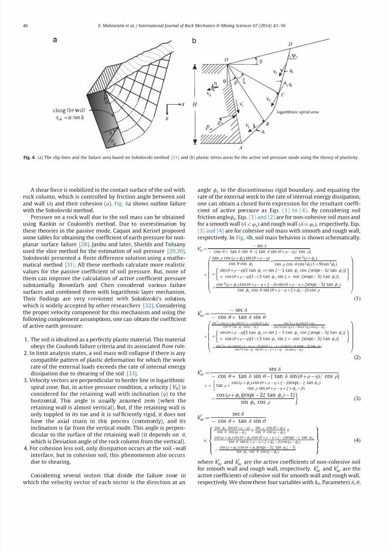
7232019 Slope Stability 201312020
httpslidepdfcomreaderfullslope-stability-201312020 414
A shear force is mobilized in the contact surface of the soil withrock column which is controlled by friction angle between soiland wall ethδ THORN and their cohesion (α ) Fig 4a shows outline failurewith the Sokolovski method
Pressure on a rock wall due to the soil mass can be obtainedusing Rankin or Coulombs method Due to overestimation bythese theories in the passive mode Caquot and Kerisel proposedsome tables for obtaining the coef 1047297cient of earth pressure for non-planar surface failure [28] Janbu and later Shields and Toluanyused the slice method for the estimation of soil pressure [2930]Sokolovski presented a 1047297nite difference solution using a mathe-matical method [31] All these methods calculate more realisticvalues for the passive coef 1047297cient of soil pressure But none of them can improve the calculation of active coef 1047297cient pressuresubstantially Rosenfarb and Chen considered various failure
surfaces and combined them with logarithmic layer mechanismTheir 1047297ndings are very consistent with Sokolovskis solutionwhich is widely accepted by other researchers [32] Consideringthe proper velocity component for this mechanism and using thefollowing complement assumptions one can obtain the coef 1047297cientof active earth pressure
1 The soil is idealized as a perfectly plastic material This materialobeys the Coulomb failure criteria and its associated 1047298ow rule
2 In limit analysis states a soil mass will collapse if there is anycompatible pattern of plastic deformation for which the workrate of the external loads exceeds the rate of internal energydissipation due to shearing of the soil [33]
3 Velocity vectors are perpendicular to border line in logarithmic
spiral zone But in active pressure condition a velocity (V 0) isconsidered for the retaining wall with inclination (η) to thehorizontal This angle is usually assumed zero (when theretaining wall is almost vertical) But if the retaining wall isonly toppled in its toe and it is suf 1047297ciently rigid it does nothave the axial strain in this process (commonly) and itsinclination is far from the vertical mode This angle is perpen-dicular to the surface of the retaining wall (it depends on θ which is Deviation angle of the rock column from the vertical)
4 For cohesion less soil only dissipation occurs at the soilndashwallinterface but in cohesion soil this phenomenon also occursdue to shearing
Considering several sectors that divide the failure zone in
which the velocity vector of each sector is the direction at an
angle ϕs to the discontinuous rigid boundary and equating the
rate of the external work to the rate of internal energy dissipationone can obtain a closed form expression for the resultant coef 1047297-cient of active pressure as Eqs (1) to (4) By considering soilfriction angleϕs Eqs (1) and (2) are for non-cohesive soil mass andfor a smooth wall ethδ oφsTHORN and rough wall ethδ frac14 φsTHORN respectively Eqs(3) and (4) are for cohesive soil mass with smooth and rough wallrespectively In Fig 4b soil mass behavior is shown schematically
ksaγ frac14
sec δ cos θ thorn tan δ sin θ frac12 tan δ sin ethθ thorn ρηTHORN= cos ρ
tan ρ cos eth ρthornϕsTHORN sin ethθ thorn ρηTHORN
cos θ cos ϕs
thorn cos 2eth ρthornϕsTHORN
cos ρ cos θ cos 2ϕseth1 thorn9tan 2ϕsTHORN
sin ethθ thorn ρηTHORNfrac123 tan ϕs thorneth sin ξ 3 tan ϕs cos ξ THORNexpeth 3ξ tan ϕsTHORN
thorn cos ethθ thorn ρηTHORNfrac121 eth 3 tan ϕs sin ξ thorn cos ξTHORNexpeth 3ξ t an ϕsTHORN
( )
thorn cos 2eth ρthornϕsTHORN cos ethθ thorn ρηthornξ β THORN sin ethθ thorn ρηthornξTHORNexpeth 3ξ tan ϕ sTHORN
cos ϕs cos θ sin ethθ thorn ρηthornξthornϕs β THORN cos ρ
0BBBBBBBBB
1CCCCCCCCCA
eth1THORN
kr aγ frac14
sec δ cos θ thorn tan δ sin θ
sin 2 ρ cos eth ρthornϕsTHORN sin ethθ thorn ρηTHORN cos ethθ thornϕs THORN
cos 2θ cos ϕs cos eth ρϕsTHORN
cos 2eth ρthornϕsTHORN cos ethθ thornϕs THORN
cos 2θ cos 2ϕseth1 thorn 9tan 2ϕsTHORN cos eth ρϕsTHORN
sin ethθ thorn ρηTHORNfrac123 tan ϕs thorneth sin ξ 3 tan ϕs cos ξ THORNexpeth 3ξ tan ϕsTHORN
thorn cos ethθ thorn ρηTHORNfrac121 eth 3 tan ϕs sin ξ thorn cos ξTHORNexpeth 3ξ t an ϕsTHORN
( )
thorn cos 2eth ρthornϕsTHORN cos ethθ thorn ρηthornξ β THORN sin ethθ thorn ρηthorn ξTHORN cos ethθ thornϕsTHORNexpeth 3ξ tan ϕsTHORN
cos 2θ cos ϕs sin ethθ thorn ρηthornξthornϕs β THORN cos eth ρϕsTHORN
0BBBBBBB
1CCCCCCCA
eth2THORN
ksac frac14
sec δ cos θ thorn tan δ sin θ frac12 tan δ sin ethθ thorn ρηTHORN= cos ρ
tan ρthorn
cos eth ρthornϕsTHORN cos ethθ thorn ρηthornξ β THORNexpeth ξ tan ϕ sTHORN
cos ρ sin ethθ thorn ρηthornξthornϕs β THORN
cos eth ρthornϕsTHORNfrac12expeth 2ξ tan ϕsTHORN 1
sin ϕs cos ρ
eth3THORN
kr ac frac14
sec δ cos θ thorn tan δ sin θ
cos ϕs sin ethθ thorn ρηTHORNcos θ cos eth ρϕsTHORN
thorn sin ρ cos ethθ thornϕs THORNcos θ cos eth ρϕs THORN
thorn
cos eth ρthornϕs THORN cos ethθ thornϕsTHORN cos ethθ thorn ρηthorn ξ β THORNexpeth ξ tan ϕsTHORNcos θ sin ethθ thorn ρηthorn ξthornϕs β THORN cos eth ρϕs THORN
cos eth ρthornϕsTHORN cos ethθ thornϕs THORNfrac12expeth 2ξ tan ϕsTHORN 1
sin ϕs cos θ cos eth ρϕs THORN
8gtgtgtltgtgtgt
9gtgtgt=gtgtgt eth4THORN
where ksaγ and k
r aγ are the active coef 1047297cients of non-cohesive soil
for smooth wall and rough wall respectively ksac and kr
ac are theactive coef 1047297cients of cohesive soil for smooth wall and rough wall
respectively We show these four variables with ka Parameters δ θ
ρ
δ
ψ
ξ
β
φ
φθη
φ
δστ =
Fig 4 (a) The slip lines and the failure area based on Sokolovski method [31] and (b) plastic stress areas for the active soil pressure mode using the theory of plasticity
E Mohtarami et al International Journal of Rock Mechanics amp Mining Sciences 67 (2014) 43ndash56 46
7232019 Slope Stability 201312020
httpslidepdfcomreaderfullslope-stability-201312020 514
β η ϕs ρ and ξ represent the friction angle between soil and rockmass deviation angle of rock column from the vertical inclinationof soil surface inclination of velocity vector of the retaining wall
the internal soil friction angle the angle between the lower boundof soil plastic zone and the upper bound of the last block Theangle between the lower and the upper bound of soil plastic zoneis shown in Fig4
To calculate the force on the topmost rock column the activecoef 1047297cient of soil mass must be 1047297rst calculated according to realconditions (one of the above four states) Eqs (1)ndash(4) should besolved for the maximum amount of ka Determination of the
maximum amount of ka depends on two variables ρ and ξ If β frac14 δ frac14 0 the results of the proposed equations are the same asRankine and Coulombs methods However this solution givesmore accurate results when the soil friction angle ethφsTHORN is greaterthan 351 and δ is about ϕ=2 or more and β a0 comparing toRankine and Coulombs methods
To evaluate the accuracy in the results of the proposed methodthey are compared with the results of 1047297nite element method andCoulomb methods (Table 1) By changing the angle of the retainingwall and soil friction angle a stress is obtained which acts on thewall in a certain depth in three methods Fig 5andashc shows thegeometry of the constructed models in Plaxis 3D Tunnel [34] If thenumerical answers are considered accurate the errors presentedin Table 1 belong to Coulomb and the proposed method ascompared to the numerical method It can be seen that the errorof Coulombs method increases with reducing the angle of theretaining wall Instead the error of the proposed theory remains inthe acceptable range
When the active coef 1047297cient of the soil mass ethkaTHORN is calculatedfrom one of above equations the force on the topmost rock
Table 1
Comparison of Coulomb and proposed methods results with numerical method
θ
(degree)ϕs
(degree)Depth(m)
FEM(KNm 2)
Coulomb(KNm 2)
Error of Coulomb()
Offeredtheory(KNm 2)
Error of offeredtheory()
0 20 6687 59881 57030 0048 59762 000240 6708 37265 27201 0270 36184 0029
5 20 6715 83122 78417 0057 81459 002040 6715 39610 36847 0070 38818 0020
10 20 6881 88358 82965 0061 89242 001040 6881 41842 38671 0076 41340 0012
15 20 6618 87411 81693 0065 85838 001840 6618 41591 38122 0083 40510 0026
20 20 6473 88573 82164 0072 86713 002140 6473 42098 38305 0090 40961 0027
25 20 6705 95639 87985 0080 94109 001640 6705 4 5196 40571 0102 44473 0016
30 20 6386 94705 86489 0087 92432 002440 6386 4 5187 39989 0115 43741 0032
35 20 6652 103092 93296 0095 100721 002340 6652 4 9460 42638 0138 48125 0027
40 20 6587 107245 96011 0105 104992 002140 6601 52522 43769 0167 50947 0030
(KNm 2)
0000
-10000
10000
-20000
-30000
-40000
-50000
-60000
-70000
-80000
-90000
-100000
-110000
-120000
Fig 5 (a) Displacement of soil and wall with θ frac14251 and ϕfrac14201 (b) displacement of soil and wall with θ frac14251 and ϕfrac14401 and (c) stress distribution and deformation in
model with ϕfrac14401 and ϕfrac14201
E Mohtarami et al International Journal of Rock Mechanics amp Mining Sciences 67 (2014) 43ndash56 47
7232019 Slope Stability 201312020
httpslidepdfcomreaderfullslope-stability-201312020 614
column of slope can be obtained by Eq (5)
pa frac1412
kaγ sh2
thornkaqqh eth5THORN
In this equation (q) is the overhead pressure in the soil part(see Fig 6b) (h) is the depth of soil at the desired point andkaq frac14 ka= cos eth β θ THORN which is known by Parandtl equilibriumcoef 1047297cient ka can be obtained from Eqs (1)ndash(4) If the soil iscohesive two forces act on the rock column a friction force withangle (δ ) and the normal vector to rock column with the amount(E ) which is de1047297ned by Eq (6) The other force is the result of cohesion between soil and rock (α ) [32]
E frac14 s
cos δ frac14 kaγ sh thorn kaqq kac c eth6THORN
in which
kac frac141= cos δ kaq
tan ϕs
eth7THORN
and γ s and c are the unit weights of the soil mass and soil cohesiverespectively
In a soil mass with cohesion there might be an area thatexperiences the tensile stress The existence of the tensile stressesin the upper body leads to the cracks and 1047297ssures in the soil massand also separation of the soil from the rock columns at lengthL0(Fig 6b) This part of soil has no direct effect on rock columnhowever its total effect is considered as a uniform load on the topof soil mass which is shown as ldquoqrdquo in Eqs (5) and (6) The length of tensile crack can be determined by setting ldquoE rdquo in Eq (6) equal tozero shown as Eq (8) [32]
L0 frac14kac c kaqq
kaγ seth8THORN
Therefore according to Fig 6a the active slide of a cohesive mass
is equal to the sum of two forces
A force with inclination equal to δ has a value of kaγ sethL L0THORN2=2acting on a lower third line segment A 0B
Surface cohesion along the contact surface with the value of aethL L0THORN
4 Stability analysis of rock slope subject to
secondary toppling failure
Discontinuities in rock often happen in an irregular mannerHence the pure toppling failure (1047298exural and blocky) is very rareand most failures occurring in nature are of blockndash1047298exural type [2] Asingle column subject to secondary blockndash1047298exural toppling is stati-cally inde1047297nite however by considering several assumptions one
can obtain an appropriate theoretical solution to calculate columninteraction forces The following simplifying assumptions for theblockndash1047298exural toppling in the present analysis have been used
Force applied by a solid rock column is the same as a columnformed by several blocks [218]
All columns in a rock mass with the potential of blockndash1047298exuraltoppling have equal safety factor equal to the safety factor forwhole slope
The basal failure plane is emanated from the toe of the slopeand oriented at an angle 10ndash201 upward from the normal tothe main discontinuities [23]
For more details related to the second condition it should besaid that in a system with various components safety factor of each component is determined by its stability But the purpose of the limit equilibrium method is the stability of the whole struc-ture In other words this method calculates the distance betweenthe present state of structure and the failure mode In rock slopesby considering the type of components and applied forces to eachcolumn or block different safety factors can be taken The 1047297nalpurpose of analysis is the stability of the whole slope for whichthe second assumption will help us Two types of columns in theblockndash1047298exural toppling mechanism can be distinguished
a) Columns with discontinuities in their base (we call themblocks) These blocks might be stable or unstable under oneof the following modes (a) sliding (b) toppling (c) slidingndash
toppling and (d) topplingndashsliding In any of the above instabil-ity modes a block will impose a certain force to the next block
b) Columns anchored to the base rock act as a cantilever beamForce applied by upper columns on a certain column as wellas its weight mobilizes a tensile stress in rock at the columnbase The column may break if this stress exceeds rock tensile
L
0 L L minus
A
3
0 L L minus
A
B
)( 0 L La minus
2
)(
20 L L
k minus
γ γ
δ
0 L
Fig 6 (a) Applied forces on the topmost column and (b) tensile cracks within a cohesive mass
E Mohtarami et al International Journal of Rock Mechanics amp Mining Sciences 67 (2014) 43ndash56 48
7232019 Slope Stability 201312020
httpslidepdfcomreaderfullslope-stability-201312020 714
strength The column may also break under shear forces whichhappen if the applied loads mobilize enough shear stress onrock at column base to overcome rock shear strength
In this paper blocks and columns are generally called columnwherever their type is not important but when their type isimportant in calculation process we will call them column orblock depending on whether they are connected or not connectedat their base respectively So the blockndash1047298exural toppling is thecombination of four modes of blocky toppling sliding 1047298exuraltoppling and shearing in the rock columns
Fig 7 shows a theoretical model for the circularndashtopplingfailure In this section an analysis method is introduced for allfour modes of blockndash1047298exural toppling In this analysis any columnwithin the slope under study (say ith column) may potentially failin 1047298exural toppling or blocky toppling mode The following casesare considered in the analysis
41 Blocky toppling failure mode
Block ldquoirdquo which is presumably subject to blocky toppling iseither stable or fails in the state of toppling sliding topplingndashsliding
or slidingndash
toppling Thus these four states of instability should beconsidered in the analysis The topmost block (adjacent to the soilmass) may similarly have one of these 1047297ve states however it isunder applied pressure by soil at one side which is calculated byEq (5) Limit equilibrium for the 1047297ve states are as follows
a) Pure toppling failure mode In this mode the block ldquoirdquo is notsliding but is subject to toppling The equilibrium state can beshown as follows (Fig 8a)
sum f x frac14 ma x sum f y frac14 ma y S ioN i tan ϕ p
T i 1 ffi pi 1 tan ϕd T i thorn 1 ffi pi thorn 1 tan ϕd Li frac14 minethhi hi 1THORN
(
eth9THORN
where f x is force along the ldquo xrdquo f y is force along the ldquo yrdquo m is
rock column mass a x is acceleration components along ldquo xrdquo a y
is acceleration components along ldquo yrdquo pi thorn 1 is normal force appliedby column ldquoithorn1rdquo on column ldquoirdquo pi 1 is normal force appliedby column ldquoi1rdquo on column ldquoirdquo T i thorn 1 is shear force applied bycolumn ldquoithorn1rdquo on column ldquoirdquo T i 1 is shear force applied bycolumn ldquoi-1rdquo on column ldquoirdquo N is the normal force at the base of column S is the shear force at the base of column ϕ p is frictionangle between block and underneath rock ϕd is friction anglealong the column interfaces Li is distance between pi 1 andfailure plane (see Fig 8) and hi is height of column i
By substituting all the forces in the above dynamic equilibriumequations for intermediate blocks (i frac14 1 to i frac14 n1) and topmostblock ethi frac14 nTHORN in directions of ldquo xrdquo and ldquo yrdquo and rotational dynamicequilibrium it can be rewritten as followsFor intermediate blocks (IB) or 8 i A IB
aTHORN w i
g ai
x frac14 wi sin ψ thorn pi thorn 1 thorn V thorni pi 1 V i S i thornc ewi cos β e
bTHORN w i
g ai
y frac14 wi cos ψ thorn T i thorn 1 T i 1 N i V i c ewi sin β e
cTHORN w i
g
t 2i thorn h
2i
3 aiθ frac14 wi sin ψ hi
2 thorn c ewi cos β ehi
2 thorn N iei
thorn pi thorn 1M i pi 1Li thornV thorn
i yi
3 T i thorn 1t i V i z i
3
ethwi cos ψ c ewi sin β eTHORNt i2 thorn
γ wt 2i
6 cos ψ eth z i thorn2 yiTHORN
8gtgtgtgtgtgtgtgtgtgtltgtgtgtgtgtgtgtgtgtgt
eth10THORN
For topmost block (TB) or 8 i A
TBaTHORN w i
g ai
x frac14 wi sin ψ thorn pns thorn V thorni pi 1 V i S i thorn c ewi cos β e
bTHORN w i
g ai
y frac14 wi cos ψ thorn pns tan δ thorn ps
s thorn pc s T i 1 N i V i c ewi sin β e
cTHORN w i
g
t 2i thorn h2
i
3 aiθ frac14 wi sin ψ hi
2 thorn c ewi cos β ehi
2 thorn N iei thorn pns M i
pi 1Li thornV thorn
i yi
3 ethwi cos ψ c ewi sin β eTHORNt i2
eth pss thorn pc
s thorn pns tan δ THORNt i
V i z i3 thorn
γ wt 2i
6 cos ψ eth z i thorn2 yiTHORN
8gtgtgtgtgtgtgtgtgtgtltgtgtgtgtgtgtgtgtgtgt
eth11THORN
where pns is vertical component of load applied by soil on rock
mass pss is tangential component of load applied by soil on rock
mass pc s is shear force on contact plane of soil and topmost
column wi is weight of column I g is acceleration of gravity a x is
component of acceleration acting on column ldquoirdquo
along the X axis
β
H
sψ
1 K
Ωα
iM
p1minusi
bt
t f
i
i - 1
L i
i - 1
iiT 1+
p1+i
i
11
minusminusiiT
1minusi
i
Fig 7 Model for investigating blockyndash1047298exural toppling failure when blocks with potential of blocky and 1047298exural toppling located the alternating binary consecutive
E Mohtarami et al International Journal of Rock Mechanics amp Mining Sciences 67 (2014) 43ndash56 49
7232019 Slope Stability 201312020
httpslidepdfcomreaderfullslope-stability-201312020 814
a y is component of acceleration acting on column ldquoirdquo along the Y
axis ai
θ angular acceleration acting on column i γ
w is unit weight
of the water yi is water level in the upstream (US) of ith column z i is water level in the downstream (DS) of ith column V thorni iswater pressure at US V
i is water pressure at DS V i is uniformwater pressure at base t i is thickness of ith rock columnregardless of its type (t b and t f for blocky and 1047298exural modesrespectively) ei is distance of applying load point at the base of column ldquoirdquo to its lower edge M i is distance between pi thorn 1 andfailure plane (see Fig 8) ψ is inclination of block base plane c e isseismic coef 1047297cient and β e is deviation angle of the seismic forcefrom the X axisConsidering ai
x frac14 ai y frac14 0 and e frac14 0 for Eqs (10a) (10b) (11a) and
(11b) and solving them for pt i 1 ie the required force for
preventing failure of block ldquoirdquo lead to the following 1047297nal results
pt i 1 frac14 pi thorn 1M i pi thorn 1
tan ϕd
F s t b thorn wi sin ψ hi
2 wi cos ψ t b
2 thorn c ewi cos β e
thorn c ewi sin β e thornV thorn
i yi
3 thornγ wt 2
b
6 cos ψ eth z i thorn2 yiTHORN V i z i
3
24 35
L 1i 8 iAIB eth12aTHORN
pt i 1 frac14
wieth sin ψ thornc e cos β eTHORNhi
2 wieth cos ψ c e sin β eTHORNt b2 thorn pn
s M i pns
tan δ F s
t b
eth pss thorn pc
s THORNt b thornV thorn
i yi
3 thornγ wt 2
b6 cos ψ eth z i thorn2 yiTHORN V i
z i3
24
35
L 1i 8 iATB eth12bTHORN
where F s is factor of safety pss and pn
s are projections of active soilforce parallel and perpendicular to block respectively pc
s is theshear force along the block contact plane Fig 9 shows theseforces clearly M i measures the distance from the failure plane tothe point of acting pi 1 The force pi 1 is applied at the middle of
block ldquoithorn1rdquo
if the block ldquoithorn1rdquo
is sliding shearing or slidingndash
toppling (Fig 10a) If the block ldquoithorn1rdquo fails in pure toppling1047298exural toppling and topplingndashsliding the position of application of force ldquo pi thorn 1rdquo can be given in a general form as inEq (13) [21]
M i frac14 λhi eth13THORN
Laboratory model tests employed by Aydan et al show that thevalue of λ should be 075 to 1 [21] According to results of theirstudies it is advisable to assume λ frac14 1 which is obviously aconservative approach and is considered in this paper(Fig 10b) pi thorn 1 acts on one third of block height from the bottomto the topmost block as soil pressure
b) Sliding failure mode In this mode ith block has only slidingpotential without blocky toppling potential Equilibrium equa-tions and some simplifying assumptions can be as follows
T i thorn 1 ffi pi thorn 1 tan ϕd e frac14 t b=2
T i 1 ffi pi 1 tan ϕd Li frac14 hi=2
S i frac14 N i tan ϕ p a x frac14 a y frac14 0
8gtlt
gteth14THORN
By considering Eqs (10) and (11) and solving equilibriumequations ps
i 1 can be calculated as follows
psi 1 frac14 pi thorn 1 thorn wi eth cos ψ c e sin β eTHORN
tan ϕ p
F s sin ψ c e cos β e
h inthornV thorni thornV i
tan ϕ p
F sV i
o 1
tan ϕ p
F stan ϕd
1
8 iAIB
eth15aTHORN
psi 1 frac14
wi sin ψ cos ψ tan ϕ p
F sthorn c e cos β e thorn sin β e
tan ϕ p
F s
h ithorn pn
s 1 tan δ tan ϕ p
F s
eth ps
s thorn pc s THORN
tan ϕ p
F sthornV thorni thorn V i
tan ϕ p
F sV i
8gtltgt
9gt=gt
1 tan ϕ p
F stan ϕd
1
8 iATB eth15bTHORN
1+i
piminus1
1+iT
1minusiT a i M
L a i
p1+i
p1minusi
1+iT
1minusiT a i M
L a i
i
i
t b t f
βegt 0
βelt 0
Fig 8 (a) Force on a single block with potential of blocky toppling failure and (b) force on a column with the potential of 1047298exural toppling failure
p s
n
c p s
s p s
total psoil
Fig 9 Forces act on the topmost rock column due to active landslide of soil mass
E Mohtarami et al International Journal of Rock Mechanics amp Mining Sciences 67 (2014) 43ndash56 50
7232019 Slope Stability 201312020
httpslidepdfcomreaderfullslope-stability-201312020 914
If pt i 1 and ps
i 1 are both positive for a block which showsinstability the block should be further examined for possibletopplingndashsliding and slidingndashtoppling failure These two statesare explained in the next sections
c) Toppling ndashsliding failure mode If pi 1 t 40 pi 1 s40 and pi 1 t 4 pi 1 t the failure happens in topplingndashsliding modeBy solving Eqs(10) and (11) and using assumptions in (16) pts
i 1 it can be calculated for intermediate blocks and thetopmost one as follows
S i frac14 N i tan ϕ p T i thorn 1 ffi pi thorn 1 tan ϕd T i 1 ffi pi 1 tan ϕd
ei frac14 0 ai x frac14 ai
θ hi
2 ai y frac14 ai
θ t b2 ai
θ Z0
(
eth16THORN
ptsi 1 frac14
1k
wifrac12eth sin ψ thorn c e cos β eTHORNeth4t 2b thornh2i 3hit b tan ϕ pTHORN
thorn eth cos ψ thornc e sin β eTHORNeth tan ϕ peth4h2i thornt 2bTHORN 3hit bTHORN
thorn1k pi thorn 1
eth4t 2b thorn4h
2i 6M ihi 6M it b tan ϕ pTHORN
thorn tan ϕd
F seth tan ϕ peth2t 2b 4h
2i THORN thorn6hit bTHORN
thorn1k
h2i 4ethV thorni V i thornV i tan ϕ pTHORN
2hi
ethV thorni yi V i z iTHORN
thorn1k
t 2b 4ethV thorni V i thornV i tan ϕ pTHORN
2 tan ϕ p
t bethV thorni yi V i z iTHORN
γ w cos ψ eth z i thorn2 yiTHORNetht b tan ϕ p thorn hiTHORN
8 iAIB eth17aTHORN
ptsi 1 frac14
1k
wi eth sin ψ thornc e cos β eTHORNeth4t 2b thorn h2i 3hit b tan ϕ pTHORN
hthorn eth cos ψ thornc e sin β eTHORNeth tan ϕ peth4h
2i thornt 2bTHORN 3hit bTHORN
ithorn
1k pn
s 4t 2b thorn4h2i thorn
tan δ
F seth tan ϕ peth2t 2b 4h
2i THORN thorn6t bhiTHORN
6M iethhi thorn t b tan ϕ pTHORN
thorn1
k
eth pss thorn pc
s THORN 6t betht b tan ϕ p thornhiTHORN 4 tan ϕ pethh2i thornt 2bTHORNh i
thorn1k
t 2b 4ethV thorni V i thornV i tan ϕ pTHORN 2 tan ϕ p
t bethV thorn
i yw V i z wTHORN
γ w cos ψ eth z w thorn2 ywTHORNetht b tan ϕ p thorn hiTHORN
thorn1k
h2i 4ethV thorni V i thorn V i tan ϕ pTHORN
2hi
ethV thorni yw V i z wTHORN
8 iATB
eth17bTHORNwhere k is
k frac14 eth4etht 2b thorn h2i THORN 6LihiTHORN tan ϕ peth6Lit b thorn4
tan ϕd
F setht 2b thornh
2i THORNTHORN
Similar to the previous cases M i and Li depend on the type of failure of the two blocks the block under examination ldquoirdquo andthe upper block ldquoithorn1rdquo Finally after calculating p ts
i 1 we mayhave one of the following states
ptsi 1o 0 Pure toppling
ptsi 1 0 Transfer from toppling mode to combined mode
ptsi 14 0 TopplingSliding
8gtltgt
d) Sliding ndashtoppling failure mode If pt i 1 and ps
i 1 are bothpositive and p t
i 1 o psi 1 the failure happens in sliding-toppling
mode By considering the dynamic equilibrium equations in (10)and (11) and using assumptions in (18) pst
i 1 can be calculated forintermediate blocks and the topmost block as follows
S i frac14 N i tan ϕ p T i thorn 1 ffi pi thorn 1 tan ϕd T i 1 ffi pi 1 tan ϕd
ei frac14 0 ai xZ0 ai
y frac14 0 aiθ frac14 0
8lt eth18THORN
pst i 1 frac14
pi thorn 1tan ϕ p
F stan ϕd 1
hi
2 t b tan ϕd thornM i
h ithorn wi cos ψ
tan ϕ p
F shi
2 t b2
thorn c e sin β e
t b2 hi
2tan ϕ p
F s
h i hi
2 V thorni thorn V itan ϕ p
F s V i
h ithorn
V thorni yi
3 V i z i
3 thornγ wt 2
b
6 cos ψ eth z i thorn2 yiTHORN
8gtgtgtgtgtltgtgtgtgtgt
9gtgtgtgtgt=gtgtgtgtgt
8 iAIB Li 1tan ϕ p
F stan ϕd
hi
2 1
eth19aTHORN
i M
p i +
1
a i M
p i + 1
i i
i + 1 i + 1
Fig10 Position of application of the normal force on block ldquo irdquo from the upper block when the upper block is (a) pure sliding shearing slidingndashtoppling type and (b) puretoppling topplingndashsliding type
E Mohtarami et al International Journal of Rock Mechanics amp Mining Sciences 67 (2014) 43ndash56 51
7232019 Slope Stability 201312020
httpslidepdfcomreaderfullslope-stability-201312020 1014
pst i 1 frac14
pns
tan ϕ p
F stan δ 1
hi
2 t b tan δ thorn M i
h ithornwi cos ψ
tan ϕ p
F s
hi
2 t b2
thornc e sin β e
t b2 hi
2tan ϕ p
F s
h i hi
2 eth pss thorn pc
s THORN tan ϕ p V thorni V itan ϕ p
F sthorn V i
h i
eth pss thorn pc s THORNt b thornV thorn
i
yi
3 V
i
z i3 thorn
γ w t 2
b6 cos ψ eth z i thorn2 yiTHORN
8gtgtgtgtgtgtgtgtlt
gtgtgtgtgtgtgtgt
9gtgtgtgtgtgtgtgt=
gtgtgtgtgtgtgtgt Li 1
tan ϕ p
F stan ϕd
hi
2
1
8 iATB eth19bTHORN
In this case M i and Li are determined as in the previous casesStability determination or the type of possible instability in thecalculated block is done as follows
pst i 1 0 Only sliding
pst i 1 0 Transfer from sliding mode to the slidingtoppling
pst i 14 0 SlidingToppling
8gtltgt
e) Stable mode When psi 1 pt
i 1 o 0 the block is stable In this
case there is no need to calculate ptsi 1 and p
st i 1 Also pi 1 is
assumed to be zero in the subsequent calculation for other blocksIf this condition happens for the topmost block the soil mass hasno effect on the blocks system In this case the secondary topplingis not a probable mode of failure However any other topplingmode may still happen
42 Flexural toppling mode
If block ldquoirdquo is connected to the rock at the base of the slopeforming a cantilever position (Fig 8b) it shows tensile strengthdue to the bending state of loading Three modes ie 1047298exuraltoppling shearing and stable state can be expected
a) Flexural toppling mode In this mode column ldquoirdquo may fail dueto bending moment acting on the column Equilibrium equa-tions used in the previous section (Eqs (10) and (11))
can be used to analyze this state of loading The following
Is it first stagen = 0
Start
input parameters
NoYes
R e d u e F
s
u s i n g a r t i f i c i a l
b e e c o l o n y
Calculation of columnrsquos
data amp optimization of k a
F s = 1
Calculate of p i (i=0-n )
Display F s as an output
End
I n c r e a s e F
s
u s i n g a r t i f i c i a l
b e e c o l o n y
n = n+1n = n+1
Refer to algorithm shown in figure 12
Fig 11 A schematic algorithm of the computer codes process
Table 2
Input parameters which are used in the developed software
Input parameters Unit Input parameters Unit
Height of slope m Inclination of soil surface degreeAverage thickness of the layers in blocky mode m Friction angle between soil and rock mass degreeAverage thickness of the layers in 1047298exural mode m Internal soil friction angle degree
Distance between the soil mass to rock slopersquos crest m Cohesive in soil mass KNm
3
Slope angle with the horizontal degree Surface cohesive between the soil mass and rock KNm 3
Inclination of top surface of slope degree Friction angle of intact rock degreeInclination of the layers degree Tensile strength of rock mass KNm 3
Inclination of the failure plane degree Cohesive of intact rock sample KNm 3
Inclination of block base plane degree Pseudo-static seismic force coef 1047297cient ndash
Friction angle between block and underneath rock degree Deviation angle of the seismic force from x axis degreeFriction angle along the block interface degree
E Mohtarami et al International Journal of Rock Mechanics amp Mining Sciences 67 (2014) 43ndash56 52
7232019 Slope Stability 201312020
httpslidepdfcomreaderfullslope-stability-201312020 1114
assumptions are applicable
T i thorn 1 frac14 pi thorn 1 tan ϕd
T i 1 frac14 pi 1 tan ϕd
ei frac14 t f =2
ai x frac14 ai y frac14 0
8gtgtgtgtltgtgtgtgt
eth20THORN
Bending moment (M ) and axial force (N ) on the column at thebase point of the column are obtained as follows
N i frac14 wi cos ψ thornT i thorn 1 T i 1 V i c ewi sin β e eth21THORN
M frac14 wieth sin ψ thorn c e cos β eTHORNhi
2thorn pi thorn 1M i thorn
V thorni yi
3
t f
2ethT i thorn 1 thorn T i 1THORN
pi 1Li V
i z i3
V iLout eth22THORN
where Lout is the eccentric water pressure at base The total stressin the column should be calculated from both ldquoM rdquo and ldquoN rdquo as
shown in Eq (23) If the total tensile stress in rock column exceeds
the tensile rock strength st the rock breaks and the column isoverturned In equilibrium conditions the tensile stress mentionedin Eq (23) is equal to the tensile strength of rock It may berewritten as Eq (24) and safety factor of rock column against thetensile stress and hence against toppling is obtained from Eq (25)
s y frac14 t f =2t frac14
Mt f
2I i
N it f
eth23THORN
M frac142I it f
st thornN it f
eth24THORN
F s frac14 st =st f =2
y eth25THORN
By substituting ldquoM rdquo and ldquoN rdquo from Eqs (21) and (22) in Eq (24) p f t
i 1 is obtained as shown in Eq (26a) for the intermediatecolumns (IC) and in Eq (26b) for the topmost column (TC columnadjacent to soil mass) where I i is the second moment of columnldquoirdquo Similar to the previous cases Li and M i depend on failure type
of column or block ldquoirdquo
and ldquoithorn 1rdquo respectively
Block is
connected at its
bottom
Start
Initial calculations
NoYes
No
Yes No
Yes
No
Yes
Yes
No
Input parameters
Calculate of amp Calculate of amp
Calculate of Calculate of
Display output ie
and failure mode
End
Fig 12 An algorithm for calculating the ldquo pi1rdquofor column ldquoirdquo
Fig 13 (a) Overview of the slope and the Haraz road and (b) the soil part on top of the slope and partially equilibrium
E Mohtarami et al International Journal of Rock Mechanics amp Mining Sciences 67 (2014) 43ndash56 53
7232019 Slope Stability 201312020
httpslidepdfcomreaderfullslope-stability-201312020 1214
p f t i 1 frac14
pi thorn 1ethM i tan ϕdt f 2
2 tan ϕdI it 2 f
THORN
thornwihi
2 eth sin ψ thornc e cos β eTHORN thorn V iLout thornV thorni yi
3 thornV i z i
3
h i2I i
t f st
F sthorn
wi eth cos ψ c e sin β eTHORN V it f
8gtgtgtgtgtltgtgtgtgtgt
9gtgtgtgtgt=gtgtgtgtgt
tan ϕd
t f
2thornLi
2 tan ϕdI i
t 2 f
1
8 iAIC eth26aTHORN
p f t i 1 frac14
pns ethM i tan δ
t f 2THORN thornwi
hi
2 eth sin ψ thornc e cos β eTHORN
thorn V iLout thornV thorni yi
3 thornV i z i
3
h ieth ps
s thorn pc s THORN
t f 2
2I it f
st
F sthorn
wieth cos ψ c e sin β e THORN thorn pss thorn pc
s V it f
8gtgtgtgtltgtgtgtgt
9gtgtgtgt=gtgtgtgt
eth tan ϕd
t f
2thorn LiTHORN
1 8 iATC eth26bTHORN
b) Shear failure mode In this mode column ldquoirdquo may fail undershear force perpendicular to column axis The force shouldobviously overcome rock shear resistance mobilized by cohe-sive (C ) and friction (φr ) in intact rock By consideringassumptions in Eq (27) and limit equilibrium equations value
of pshi 1 for intermediate and topmost column it is obtained
from Eqs (28a) and (28b) respectively
T i thorn 1 ffi pi thorn 1 tan ϕd ei frac14 t f =2 ai x frac14 ai
y frac14 0
T i 1 ffi pi 1 tan ϕd S i frac14 N i tan ϕr thorn Ct f
(
eth27THORN
pshi 1 frac14 pi thorn 1 thorn wi eth cos ψ c e sin β eTHORN
tan ϕr
F s sin ψ c e cos β e
thorn V thorni thorn V itan ϕr
F s V i Ct f
) 8 iA IC 1
tan ϕr
F stan ϕd
1
eth28aTHORN
pshi 1 frac14 pn
s eth1 tan δ tan ϕr
F sTHORN wi eth cos ψ c e sin β eTHORN
tan ϕr
F s
sin ψ c e cos β e
8 iATC
eth pss thorn pc
s THORNtan ϕr
F sthorn V thorni thornV i
tan ϕr
F sV i Ct f
)
1 tan ϕr
F stan ϕd
1
eth28bTHORN
c) Stable mode When p f t i 1 psh
i 1r0 the column is stable and pi 1 is assumed to be zero in the subsequent calculation forother columns or blocks
5 Computer code developed for stability analysis
In the previous section a complete solution for circularndashtop-pling failure was presented To assess the overall stability of aslope with the combination of soil mass and rock columns thealgorithm shown in Fig 11 is proposed A computer code wasdeveloped using a user friend environment This algorithm wasused for slop stability evaluation and the calculation of safetyfactor Table 2 shows the input parameters The output for theintermediate stage of calculations is the forces between thecolumns ie pi 1 and pi thorn 1 for each column The 1047297nal output isthe force required to support toe column p0 and the safety factorof slope In this algorithm the coef 1047297cient of lateral earth pressurein the active mode ka is calculated using Eqs (1) to (4) for varioussoil conditions ldquoArti1047297cial bee colony optimizationrdquo algorithm wasused to optimize ka value Having found ka we calculated pi thorn 1 forthe topmost column using Eq (5) The values of pi 1 and pi thorn 1 iethe forces applied at both sides of each column are then calculatedaccording to the algorithm shown in Fig 12 and the formulationsdescribed in the previous section
53
25
45
6 7 0 m
3 1 9
2 m
77
Soil mass
Fig 14 A schematicof the slope located in Haraz
Table 3
Conducted tests in soil and rock parts
Conducted tests in rock parts Conducted tests in soil part
Test name Description Test name Description
Direct shear tests ϕfrac1428661 c jfrac14008 MPa Direct shear tests (using normal stress 5 Kgcm3) c frac14819 KNm 2 ϕfrac1427581Non-encapsulated strain s
avec frac14 14951 MPa Non-encapsulated strain sc frac142843 Kgcm 3
Dry and saturation density (Kgcm 3) γ dry frac14 262 γ sat frac14 2677 Determinat ion of speci1047297c gravity GS frac14259
Chemical testing of groundwater Water is not acidic or alkaline Chemical testing of groundwater Water is not acidic or alkalinePetrographic characteristics (dominant mineral) Quartz potassic feldspar biotite Dry and saturation density (Kgcm 3) γ dry frac14 1577 γ sat frac14 1968
Porosity and saturation percent n frac14 516 s frac14 2578 Porosity and saturation percent n frac14 391 s frac14 70Determination E and υ (21 samples) υ frac14 0239 E frac14 1607 ethGPaTHORN Determination E and υ υ frac14 036 E frac14 1250 ethKg =cm2THORN
The ultrasonic wave velocity V com frac14 3220 V sh frac14 1853 ethm=sTHORN The ultrasonic wave velocity V com frac14 1155 V sh frac14 540 ethm=sTHORN
E Mohtarami et al International Journal of Rock Mechanics amp Mining Sciences 67 (2014) 43ndash56 54
7232019 Slope Stability 201312020
httpslidepdfcomreaderfullslope-stability-201312020 1314
By 1047297nding p0 (ie p i 1 for toe column) the stability of a slopesubject to circular-toppling failure can be judged as follows
p04 0 Unstable
p0 frac14 0 Limit equilibrium condition
p0o 0 Stable
8gtlt
gt It should be noted that safety factor ethF sTHORN is set equal to 1 for
1047297nding p0 at the initial stage If p0 frac14 0 at the initial calculations theslope is at equilibrium state and calculation is no longer necessaryIf p040 then the slope is unstable and the value of F s is reducedgradually until p0 frac14 0 The 1047297nal calculated F s is the actual safetyfactor of the slope Similarly if p0o0 then the slope is stable Theactual safety factor is found by increasing the amount of F s incalculation loop till p0 frac14 0 The 1047297nal calculated F s is the actualsafety factor of the slope The increase or reduction of F s anddetermination of the optimum value are done using the arti1047297cialbee colony algorithm (Fig 11) In the previous studies the blockshave been alternately considered in blocky or 1047298exural topplingmode The proposed solution in this paper freely allows for anycombination
6 Case study
A real case including a slope subject to failure was studiedusing the proposed method This slope is located in Vana villagealong Haraz road in northern Iran 70 km from Amol city Theslope consists of rhyolite tuff overlooking Haraz road with thepotential of toppling Fig 13 shows the general view of the slopeand Fig 14 depicts the slope schematically As can be seen in these1047297gures a large amount of sediments and volcanic debris isdumped on the top of slope behind the rock columns This massgenerates the soil active pressure Ongoing erosion of the sedi-ments and volcanic rock not only increases the active pressure butalso causes the rock falls which have already caused some
accidents and injuries Due to the concern of possible failure of block rocks a research project was organized by research instituteof the Ministry of Roads and Urban Development for the evalua-tion of the general stability of the slope The existing residentialand commercial buildings next to this slope helped authoritiesaccept the minimum F S to be equal to 155
A number of exploration drillings were performed within theslope to obtain the geo-mechanical properties Moreover observa-tions were made through the existing tunnel of an old coal mine inthe area Table 3 shows the main obtained data used for this study
The stability of the slope in Vana village was analyzed using theproposed method and the developed code The code shows severalitems as outputs (a) Geometry and geo-mechanical parameterswhich are partially inputted by the user and partially calculated
by the code (b) forces between the columns ( pi1 and p ithorn1) and
possible failure mode of each block and (c) safety factor andstability state of the slope Furthermore we can obtain the appliedforce on topmost block by the soil by running the computer code
The analysis revealed that safety factor for this slope was equalto 164 for combined circularndashtoppling failure which was higherthan the acceptable 1047297gure by authorities The slope was found atstable state however it should be noted that due to futureerosions soil value and active soil pressure may increase during
the years Thus update evaluation may be necessary from time totime Moreover despite the general stability of this slope localrock falls can still happen Fig 15 shows potential rock falls due toerosion resulted by the running water
7 Conclusions
Different types of the toppling failure are still a major instabil-ity for slopes in nature and slopes all over the world Combinedcircularndashtoppling failure is a kind of instability not studied beforein details In this paper a complete solution was presented for thistype of failure A new formulation was developed to investigatethe stability of slope components (the soil and rock part)
The developed solution in this paper has taken all the effectiveparameters (external forces water pressure and earthquake) intoaccount Every column can be in any mode of failure including astable mode The presented solution unstable forms were widelyanalyzed from the point of limit equilibrium method in discontin-uous rock and allowed for any combination of failure in thecolumns ie failure mode of each column could be different withthe mode of neighboring columns Another advantage of theproposed solution is that the topmost column can have anyinclination and the applied force by soil mass can be calculatedby plasticity theory which has good accuracy
A computer code was developed to ease the use of the proposedsolution The code was simple and fast it gave the 1047297nal state of stability as well as safety factor of the slope By using this code the
effect of different parameters (like block inclination friction etc) onstability can be simply and quickly studied Such a study can helpthe users decide on the necessary measures for making the slopemore stable
References
[1] Goodman RE Bray JW Toppling of rock slopes In Boulder CO Proceedings of the specialty conference on rock engineering for foundations and slopesNew York American Society of Civil Engineers 15ndash18 August 1976 p 201ndash23
[2] Amini M Majdi A Veshadi MA Stability analysis of rock slopes against blockndash
1047298exure toppling failure Int J Rock Mech Rock Eng 201245(4)519ndash32[3] Collin A Recherches expeacuterimentaux sur les glissements spontaneacutes des terrains
argileux Paris Carilian-Goeurley et Dalmont [4] Taylor DW Stability of Earth slopes J Boston Soc Civ Eng 19371337ndash86
[5] Willie DC Mah CW Rock slope engineering (civil and mining) 4th EditionUK Spoon Press London Taylor and Francis Group 2004[6] Bishop AW The use of the slip circle in the stability analysis of slopes
Geacuteotechnique 195557ndash17[7] Nonveiller E The stability analysis of slopes with a slide surface of general
shape Proc 6th Int Conf Soil Mech Found Eng Montreal 1965279ndash93[8] Morgenstern NR Price VE The analysis of the stability of generalised slip
surfaces Geacuteotechnique 19651579ndash93[9] Chen Z Morgenstern NR Extensions to the generalized method of slices for
stability analysis Can Geotech J 198320(1)104ndash19[10] Muller L New considerations of the Vaiont slide Felsmech Engenieurgeologie
19686(1)1ndash91[11] Ashby J Sliding and toppling modes of failure in models and jointed rock
slopes [MSc thesis] London United Kingdom London University ImperialCollege 1971
[12] Hofmann H Kinematische modellstudien zum boschungs-problem in regal-massig geklufteten medien [PhD thesis] Karlsruhe Germany University of Karlsruhe 1972
[13] De Freitas MH Watters RJ Some 1047297eld examples of toppling failure Geacuteotech-
nique 197323495ndash514
Fig 15 Erosion and destructionwithin rock section of the slope
E Mohtarami et al International Journal of Rock Mechanics amp Mining Sciences 67 (2014) 43ndash56 55
7232019 Slope Stability 201312020
httpslidepdfcomreaderfullslope-stability-201312020 1414
[14] Whyte RJA Study of progressive hanging wall caving at chambishi coppermine in Zambia using the base friction model concept [MSc thesis] LondonUnited Kingdom London University Imperial College 1973
[15] Soto CA Comparative study of slope modelling techniques for fracturedground [MSc thesis] London United Kingdom London University ImperialCollege 1974
[16] Zanbak C Design charts for rock slopes susceptible to toppling J Geotech EngASCE 19831091039ndash62
[17] Goodman R Shi G Block theory and its application to rock engineeringEnglewood Cliffs New Jersey Prentice-Hall 1985 338
[18] Aydan Ouml Shimizu Y Ichikawa Y The effective failure modes and stability of slopes
in rock mass with two discontinuity sets Rock Mech Rock Eng 198922(3)163ndash88[19] Davies JN Smith PLP Flexural toppling of siltstones during a temporary
excavation for a bridge foundation in North Devon In Hadson JA editorComprehensive rock engineering Oxford Pergamon Press 1993 p 759ndash75
[20] Zaruba Q Mencl V Engineering geology Amsterdam Elsevier 1976[21] Aydan Ouml Kawamoto T Stability of slopes and underground openings against
1047298exural toppling and their stabilization Rock Mech Rock Eng 199225(3)143ndash65[22] Adhikary DP Dyskin AV Jewell RJ Modeling of 1047298exural toppling failures of
rock slopes In Proceedings of the eighth international congress rockmechanics Tokyo 1995 p 25ndash9
[23] Adhikary DP Dyskin AV Jewell RJ Stewart DP A study of the mechanism of 1047298exural toppling failure of rock slopes Rock Mech Rock Eng 199730(2)75ndash93
[24] Adhikary DP Dyskin AV Modeling of progressive and instantaneous failure of foliated rock slopes Rock Mech Rock Eng 200740(4)349ndash62
[25] Aydan Ouml Amini M An experimental study on rock slopes against 1047298exuraltoppling failure under dynamic loading and some theoretical considerationsfor its stability assessment J Sch Mar Sci Technol 20097(2)25 ndash40
[26] Braja MD Principles of geotechnical engineering 7th edition Stamford USACengage learning 2010
[27] Lambe TW Whitman RV Soil mechanics Massachusetts institute of technol-ogy Cambridge Massachusetts John Wiley and Sons 1969
[28] Caquot A Kerisel J Table for the calculation of passive pressure activepressure and bearing capacity of foundations (trans by MA Bec London)Paris Gauthier-Villars 1948
[29] Janbu N 4thEarth pressure and bearing capacity calculations by generalizedprocedure of slices Vol 2 London ICSMFE 1957 207ndash12
[30] Shields DH Tolunay AZ Passive pressure coef 1047297cients by method of slices JSMFD AS CE 197399(SM 12)S1043ndash53
[31] Sokolovski VV Statics of granular media Oxford Pergamon Press 1965 [32] Behnia K Tabatabai AM Soil mechanics 2nd Ed Tehran Tehran University
Press 1987[33] Chen WF Rosenfarb JL Limit analysis solutions of Earth pressure problems
Jpn S oc Soil Mech Found Eng 197313(4)45ndash60[34] PLAXIS V8 Finite element code for soil and rock analyses PLAXIS-3D
Reference manual Edited by Brinkgreve et al DUT The Netherlands langwwwplaxisnl2004rang
E Mohtarami et al International Journal of Rock Mechanics amp Mining Sciences 67 (2014) 43ndash56 56
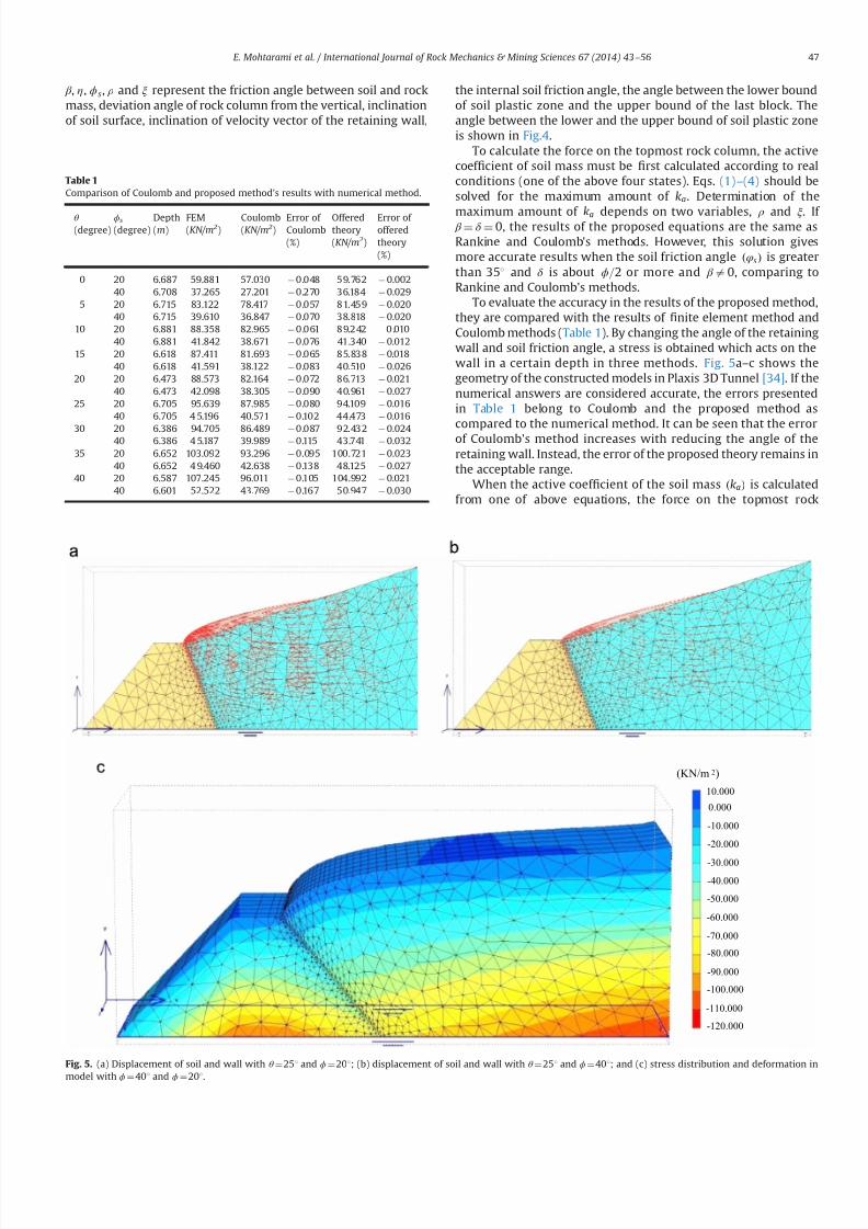
7232019 Slope Stability 201312020
httpslidepdfcomreaderfullslope-stability-201312020 514
β η ϕs ρ and ξ represent the friction angle between soil and rockmass deviation angle of rock column from the vertical inclinationof soil surface inclination of velocity vector of the retaining wall
the internal soil friction angle the angle between the lower boundof soil plastic zone and the upper bound of the last block Theangle between the lower and the upper bound of soil plastic zoneis shown in Fig4
To calculate the force on the topmost rock column the activecoef 1047297cient of soil mass must be 1047297rst calculated according to realconditions (one of the above four states) Eqs (1)ndash(4) should besolved for the maximum amount of ka Determination of the
maximum amount of ka depends on two variables ρ and ξ If β frac14 δ frac14 0 the results of the proposed equations are the same asRankine and Coulombs methods However this solution givesmore accurate results when the soil friction angle ethφsTHORN is greaterthan 351 and δ is about ϕ=2 or more and β a0 comparing toRankine and Coulombs methods
To evaluate the accuracy in the results of the proposed methodthey are compared with the results of 1047297nite element method andCoulomb methods (Table 1) By changing the angle of the retainingwall and soil friction angle a stress is obtained which acts on thewall in a certain depth in three methods Fig 5andashc shows thegeometry of the constructed models in Plaxis 3D Tunnel [34] If thenumerical answers are considered accurate the errors presentedin Table 1 belong to Coulomb and the proposed method ascompared to the numerical method It can be seen that the errorof Coulombs method increases with reducing the angle of theretaining wall Instead the error of the proposed theory remains inthe acceptable range
When the active coef 1047297cient of the soil mass ethkaTHORN is calculatedfrom one of above equations the force on the topmost rock
Table 1
Comparison of Coulomb and proposed methods results with numerical method
θ
(degree)ϕs
(degree)Depth(m)
FEM(KNm 2)
Coulomb(KNm 2)
Error of Coulomb()
Offeredtheory(KNm 2)
Error of offeredtheory()
0 20 6687 59881 57030 0048 59762 000240 6708 37265 27201 0270 36184 0029
5 20 6715 83122 78417 0057 81459 002040 6715 39610 36847 0070 38818 0020
10 20 6881 88358 82965 0061 89242 001040 6881 41842 38671 0076 41340 0012
15 20 6618 87411 81693 0065 85838 001840 6618 41591 38122 0083 40510 0026
20 20 6473 88573 82164 0072 86713 002140 6473 42098 38305 0090 40961 0027
25 20 6705 95639 87985 0080 94109 001640 6705 4 5196 40571 0102 44473 0016
30 20 6386 94705 86489 0087 92432 002440 6386 4 5187 39989 0115 43741 0032
35 20 6652 103092 93296 0095 100721 002340 6652 4 9460 42638 0138 48125 0027
40 20 6587 107245 96011 0105 104992 002140 6601 52522 43769 0167 50947 0030
(KNm 2)
0000
-10000
10000
-20000
-30000
-40000
-50000
-60000
-70000
-80000
-90000
-100000
-110000
-120000
Fig 5 (a) Displacement of soil and wall with θ frac14251 and ϕfrac14201 (b) displacement of soil and wall with θ frac14251 and ϕfrac14401 and (c) stress distribution and deformation in
model with ϕfrac14401 and ϕfrac14201
E Mohtarami et al International Journal of Rock Mechanics amp Mining Sciences 67 (2014) 43ndash56 47
7232019 Slope Stability 201312020
httpslidepdfcomreaderfullslope-stability-201312020 614
column of slope can be obtained by Eq (5)
pa frac1412
kaγ sh2
thornkaqqh eth5THORN
In this equation (q) is the overhead pressure in the soil part(see Fig 6b) (h) is the depth of soil at the desired point andkaq frac14 ka= cos eth β θ THORN which is known by Parandtl equilibriumcoef 1047297cient ka can be obtained from Eqs (1)ndash(4) If the soil iscohesive two forces act on the rock column a friction force withangle (δ ) and the normal vector to rock column with the amount(E ) which is de1047297ned by Eq (6) The other force is the result of cohesion between soil and rock (α ) [32]
E frac14 s
cos δ frac14 kaγ sh thorn kaqq kac c eth6THORN
in which
kac frac141= cos δ kaq
tan ϕs
eth7THORN
and γ s and c are the unit weights of the soil mass and soil cohesiverespectively
In a soil mass with cohesion there might be an area thatexperiences the tensile stress The existence of the tensile stressesin the upper body leads to the cracks and 1047297ssures in the soil massand also separation of the soil from the rock columns at lengthL0(Fig 6b) This part of soil has no direct effect on rock columnhowever its total effect is considered as a uniform load on the topof soil mass which is shown as ldquoqrdquo in Eqs (5) and (6) The length of tensile crack can be determined by setting ldquoE rdquo in Eq (6) equal tozero shown as Eq (8) [32]
L0 frac14kac c kaqq
kaγ seth8THORN
Therefore according to Fig 6a the active slide of a cohesive mass
is equal to the sum of two forces
A force with inclination equal to δ has a value of kaγ sethL L0THORN2=2acting on a lower third line segment A 0B
Surface cohesion along the contact surface with the value of aethL L0THORN
4 Stability analysis of rock slope subject to
secondary toppling failure
Discontinuities in rock often happen in an irregular mannerHence the pure toppling failure (1047298exural and blocky) is very rareand most failures occurring in nature are of blockndash1047298exural type [2] Asingle column subject to secondary blockndash1047298exural toppling is stati-cally inde1047297nite however by considering several assumptions one
can obtain an appropriate theoretical solution to calculate columninteraction forces The following simplifying assumptions for theblockndash1047298exural toppling in the present analysis have been used
Force applied by a solid rock column is the same as a columnformed by several blocks [218]
All columns in a rock mass with the potential of blockndash1047298exuraltoppling have equal safety factor equal to the safety factor forwhole slope
The basal failure plane is emanated from the toe of the slopeand oriented at an angle 10ndash201 upward from the normal tothe main discontinuities [23]
For more details related to the second condition it should besaid that in a system with various components safety factor of each component is determined by its stability But the purpose of the limit equilibrium method is the stability of the whole struc-ture In other words this method calculates the distance betweenthe present state of structure and the failure mode In rock slopesby considering the type of components and applied forces to eachcolumn or block different safety factors can be taken The 1047297nalpurpose of analysis is the stability of the whole slope for whichthe second assumption will help us Two types of columns in theblockndash1047298exural toppling mechanism can be distinguished
a) Columns with discontinuities in their base (we call themblocks) These blocks might be stable or unstable under oneof the following modes (a) sliding (b) toppling (c) slidingndash
toppling and (d) topplingndashsliding In any of the above instabil-ity modes a block will impose a certain force to the next block
b) Columns anchored to the base rock act as a cantilever beamForce applied by upper columns on a certain column as wellas its weight mobilizes a tensile stress in rock at the columnbase The column may break if this stress exceeds rock tensile
L
0 L L minus
A
3
0 L L minus
A
B
)( 0 L La minus
2
)(
20 L L
k minus
γ γ
δ
0 L
Fig 6 (a) Applied forces on the topmost column and (b) tensile cracks within a cohesive mass
E Mohtarami et al International Journal of Rock Mechanics amp Mining Sciences 67 (2014) 43ndash56 48
7232019 Slope Stability 201312020
httpslidepdfcomreaderfullslope-stability-201312020 714
strength The column may also break under shear forces whichhappen if the applied loads mobilize enough shear stress onrock at column base to overcome rock shear strength
In this paper blocks and columns are generally called columnwherever their type is not important but when their type isimportant in calculation process we will call them column orblock depending on whether they are connected or not connectedat their base respectively So the blockndash1047298exural toppling is thecombination of four modes of blocky toppling sliding 1047298exuraltoppling and shearing in the rock columns
Fig 7 shows a theoretical model for the circularndashtopplingfailure In this section an analysis method is introduced for allfour modes of blockndash1047298exural toppling In this analysis any columnwithin the slope under study (say ith column) may potentially failin 1047298exural toppling or blocky toppling mode The following casesare considered in the analysis
41 Blocky toppling failure mode
Block ldquoirdquo which is presumably subject to blocky toppling iseither stable or fails in the state of toppling sliding topplingndashsliding
or slidingndash
toppling Thus these four states of instability should beconsidered in the analysis The topmost block (adjacent to the soilmass) may similarly have one of these 1047297ve states however it isunder applied pressure by soil at one side which is calculated byEq (5) Limit equilibrium for the 1047297ve states are as follows
a) Pure toppling failure mode In this mode the block ldquoirdquo is notsliding but is subject to toppling The equilibrium state can beshown as follows (Fig 8a)
sum f x frac14 ma x sum f y frac14 ma y S ioN i tan ϕ p
T i 1 ffi pi 1 tan ϕd T i thorn 1 ffi pi thorn 1 tan ϕd Li frac14 minethhi hi 1THORN
(
eth9THORN
where f x is force along the ldquo xrdquo f y is force along the ldquo yrdquo m is
rock column mass a x is acceleration components along ldquo xrdquo a y
is acceleration components along ldquo yrdquo pi thorn 1 is normal force appliedby column ldquoithorn1rdquo on column ldquoirdquo pi 1 is normal force appliedby column ldquoi1rdquo on column ldquoirdquo T i thorn 1 is shear force applied bycolumn ldquoithorn1rdquo on column ldquoirdquo T i 1 is shear force applied bycolumn ldquoi-1rdquo on column ldquoirdquo N is the normal force at the base of column S is the shear force at the base of column ϕ p is frictionangle between block and underneath rock ϕd is friction anglealong the column interfaces Li is distance between pi 1 andfailure plane (see Fig 8) and hi is height of column i
By substituting all the forces in the above dynamic equilibriumequations for intermediate blocks (i frac14 1 to i frac14 n1) and topmostblock ethi frac14 nTHORN in directions of ldquo xrdquo and ldquo yrdquo and rotational dynamicequilibrium it can be rewritten as followsFor intermediate blocks (IB) or 8 i A IB
aTHORN w i
g ai
x frac14 wi sin ψ thorn pi thorn 1 thorn V thorni pi 1 V i S i thornc ewi cos β e
bTHORN w i
g ai
y frac14 wi cos ψ thorn T i thorn 1 T i 1 N i V i c ewi sin β e
cTHORN w i
g
t 2i thorn h
2i
3 aiθ frac14 wi sin ψ hi
2 thorn c ewi cos β ehi
2 thorn N iei
thorn pi thorn 1M i pi 1Li thornV thorn
i yi
3 T i thorn 1t i V i z i
3
ethwi cos ψ c ewi sin β eTHORNt i2 thorn
γ wt 2i
6 cos ψ eth z i thorn2 yiTHORN
8gtgtgtgtgtgtgtgtgtgtltgtgtgtgtgtgtgtgtgtgt
eth10THORN
For topmost block (TB) or 8 i A
TBaTHORN w i
g ai
x frac14 wi sin ψ thorn pns thorn V thorni pi 1 V i S i thorn c ewi cos β e
bTHORN w i
g ai
y frac14 wi cos ψ thorn pns tan δ thorn ps
s thorn pc s T i 1 N i V i c ewi sin β e
cTHORN w i
g
t 2i thorn h2
i
3 aiθ frac14 wi sin ψ hi
2 thorn c ewi cos β ehi
2 thorn N iei thorn pns M i
pi 1Li thornV thorn
i yi
3 ethwi cos ψ c ewi sin β eTHORNt i2
eth pss thorn pc
s thorn pns tan δ THORNt i
V i z i3 thorn
γ wt 2i
6 cos ψ eth z i thorn2 yiTHORN
8gtgtgtgtgtgtgtgtgtgtltgtgtgtgtgtgtgtgtgtgt
eth11THORN
where pns is vertical component of load applied by soil on rock
mass pss is tangential component of load applied by soil on rock
mass pc s is shear force on contact plane of soil and topmost
column wi is weight of column I g is acceleration of gravity a x is
component of acceleration acting on column ldquoirdquo
along the X axis
β
H
sψ
1 K
Ωα
iM
p1minusi
bt
t f
i
i - 1
L i
i - 1
iiT 1+
p1+i
i
11
minusminusiiT
1minusi
i
Fig 7 Model for investigating blockyndash1047298exural toppling failure when blocks with potential of blocky and 1047298exural toppling located the alternating binary consecutive
E Mohtarami et al International Journal of Rock Mechanics amp Mining Sciences 67 (2014) 43ndash56 49
7232019 Slope Stability 201312020
httpslidepdfcomreaderfullslope-stability-201312020 814
a y is component of acceleration acting on column ldquoirdquo along the Y
axis ai
θ angular acceleration acting on column i γ
w is unit weight
of the water yi is water level in the upstream (US) of ith column z i is water level in the downstream (DS) of ith column V thorni iswater pressure at US V
i is water pressure at DS V i is uniformwater pressure at base t i is thickness of ith rock columnregardless of its type (t b and t f for blocky and 1047298exural modesrespectively) ei is distance of applying load point at the base of column ldquoirdquo to its lower edge M i is distance between pi thorn 1 andfailure plane (see Fig 8) ψ is inclination of block base plane c e isseismic coef 1047297cient and β e is deviation angle of the seismic forcefrom the X axisConsidering ai
x frac14 ai y frac14 0 and e frac14 0 for Eqs (10a) (10b) (11a) and
(11b) and solving them for pt i 1 ie the required force for
preventing failure of block ldquoirdquo lead to the following 1047297nal results
pt i 1 frac14 pi thorn 1M i pi thorn 1
tan ϕd
F s t b thorn wi sin ψ hi
2 wi cos ψ t b
2 thorn c ewi cos β e
thorn c ewi sin β e thornV thorn
i yi
3 thornγ wt 2
b
6 cos ψ eth z i thorn2 yiTHORN V i z i
3
24 35
L 1i 8 iAIB eth12aTHORN
pt i 1 frac14
wieth sin ψ thornc e cos β eTHORNhi
2 wieth cos ψ c e sin β eTHORNt b2 thorn pn
s M i pns
tan δ F s
t b
eth pss thorn pc
s THORNt b thornV thorn
i yi
3 thornγ wt 2
b6 cos ψ eth z i thorn2 yiTHORN V i
z i3
24
35
L 1i 8 iATB eth12bTHORN
where F s is factor of safety pss and pn
s are projections of active soilforce parallel and perpendicular to block respectively pc
s is theshear force along the block contact plane Fig 9 shows theseforces clearly M i measures the distance from the failure plane tothe point of acting pi 1 The force pi 1 is applied at the middle of
block ldquoithorn1rdquo
if the block ldquoithorn1rdquo
is sliding shearing or slidingndash
toppling (Fig 10a) If the block ldquoithorn1rdquo fails in pure toppling1047298exural toppling and topplingndashsliding the position of application of force ldquo pi thorn 1rdquo can be given in a general form as inEq (13) [21]
M i frac14 λhi eth13THORN
Laboratory model tests employed by Aydan et al show that thevalue of λ should be 075 to 1 [21] According to results of theirstudies it is advisable to assume λ frac14 1 which is obviously aconservative approach and is considered in this paper(Fig 10b) pi thorn 1 acts on one third of block height from the bottomto the topmost block as soil pressure
b) Sliding failure mode In this mode ith block has only slidingpotential without blocky toppling potential Equilibrium equa-tions and some simplifying assumptions can be as follows
T i thorn 1 ffi pi thorn 1 tan ϕd e frac14 t b=2
T i 1 ffi pi 1 tan ϕd Li frac14 hi=2
S i frac14 N i tan ϕ p a x frac14 a y frac14 0
8gtlt
gteth14THORN
By considering Eqs (10) and (11) and solving equilibriumequations ps
i 1 can be calculated as follows
psi 1 frac14 pi thorn 1 thorn wi eth cos ψ c e sin β eTHORN
tan ϕ p
F s sin ψ c e cos β e
h inthornV thorni thornV i
tan ϕ p
F sV i
o 1
tan ϕ p
F stan ϕd
1
8 iAIB
eth15aTHORN
psi 1 frac14
wi sin ψ cos ψ tan ϕ p
F sthorn c e cos β e thorn sin β e
tan ϕ p
F s
h ithorn pn
s 1 tan δ tan ϕ p
F s
eth ps
s thorn pc s THORN
tan ϕ p
F sthornV thorni thorn V i
tan ϕ p
F sV i
8gtltgt
9gt=gt
1 tan ϕ p
F stan ϕd
1
8 iATB eth15bTHORN
1+i
piminus1
1+iT
1minusiT a i M
L a i
p1+i
p1minusi
1+iT
1minusiT a i M
L a i
i
i
t b t f
βegt 0
βelt 0
Fig 8 (a) Force on a single block with potential of blocky toppling failure and (b) force on a column with the potential of 1047298exural toppling failure
p s
n
c p s
s p s
total psoil
Fig 9 Forces act on the topmost rock column due to active landslide of soil mass
E Mohtarami et al International Journal of Rock Mechanics amp Mining Sciences 67 (2014) 43ndash56 50
7232019 Slope Stability 201312020
httpslidepdfcomreaderfullslope-stability-201312020 914
If pt i 1 and ps
i 1 are both positive for a block which showsinstability the block should be further examined for possibletopplingndashsliding and slidingndashtoppling failure These two statesare explained in the next sections
c) Toppling ndashsliding failure mode If pi 1 t 40 pi 1 s40 and pi 1 t 4 pi 1 t the failure happens in topplingndashsliding modeBy solving Eqs(10) and (11) and using assumptions in (16) pts
i 1 it can be calculated for intermediate blocks and thetopmost one as follows
S i frac14 N i tan ϕ p T i thorn 1 ffi pi thorn 1 tan ϕd T i 1 ffi pi 1 tan ϕd
ei frac14 0 ai x frac14 ai
θ hi
2 ai y frac14 ai
θ t b2 ai
θ Z0
(
eth16THORN
ptsi 1 frac14
1k
wifrac12eth sin ψ thorn c e cos β eTHORNeth4t 2b thornh2i 3hit b tan ϕ pTHORN
thorn eth cos ψ thornc e sin β eTHORNeth tan ϕ peth4h2i thornt 2bTHORN 3hit bTHORN
thorn1k pi thorn 1
eth4t 2b thorn4h
2i 6M ihi 6M it b tan ϕ pTHORN
thorn tan ϕd
F seth tan ϕ peth2t 2b 4h
2i THORN thorn6hit bTHORN
thorn1k
h2i 4ethV thorni V i thornV i tan ϕ pTHORN
2hi
ethV thorni yi V i z iTHORN
thorn1k
t 2b 4ethV thorni V i thornV i tan ϕ pTHORN
2 tan ϕ p
t bethV thorni yi V i z iTHORN
γ w cos ψ eth z i thorn2 yiTHORNetht b tan ϕ p thorn hiTHORN
8 iAIB eth17aTHORN
ptsi 1 frac14
1k
wi eth sin ψ thornc e cos β eTHORNeth4t 2b thorn h2i 3hit b tan ϕ pTHORN
hthorn eth cos ψ thornc e sin β eTHORNeth tan ϕ peth4h
2i thornt 2bTHORN 3hit bTHORN
ithorn
1k pn
s 4t 2b thorn4h2i thorn
tan δ
F seth tan ϕ peth2t 2b 4h
2i THORN thorn6t bhiTHORN
6M iethhi thorn t b tan ϕ pTHORN
thorn1
k
eth pss thorn pc
s THORN 6t betht b tan ϕ p thornhiTHORN 4 tan ϕ pethh2i thornt 2bTHORNh i
thorn1k
t 2b 4ethV thorni V i thornV i tan ϕ pTHORN 2 tan ϕ p
t bethV thorn
i yw V i z wTHORN
γ w cos ψ eth z w thorn2 ywTHORNetht b tan ϕ p thorn hiTHORN
thorn1k
h2i 4ethV thorni V i thorn V i tan ϕ pTHORN
2hi
ethV thorni yw V i z wTHORN
8 iATB
eth17bTHORNwhere k is
k frac14 eth4etht 2b thorn h2i THORN 6LihiTHORN tan ϕ peth6Lit b thorn4
tan ϕd
F setht 2b thornh
2i THORNTHORN
Similar to the previous cases M i and Li depend on the type of failure of the two blocks the block under examination ldquoirdquo andthe upper block ldquoithorn1rdquo Finally after calculating p ts
i 1 we mayhave one of the following states
ptsi 1o 0 Pure toppling
ptsi 1 0 Transfer from toppling mode to combined mode
ptsi 14 0 TopplingSliding
8gtltgt
d) Sliding ndashtoppling failure mode If pt i 1 and ps
i 1 are bothpositive and p t
i 1 o psi 1 the failure happens in sliding-toppling
mode By considering the dynamic equilibrium equations in (10)and (11) and using assumptions in (18) pst
i 1 can be calculated forintermediate blocks and the topmost block as follows
S i frac14 N i tan ϕ p T i thorn 1 ffi pi thorn 1 tan ϕd T i 1 ffi pi 1 tan ϕd
ei frac14 0 ai xZ0 ai
y frac14 0 aiθ frac14 0
8lt eth18THORN
pst i 1 frac14
pi thorn 1tan ϕ p
F stan ϕd 1
hi
2 t b tan ϕd thornM i
h ithorn wi cos ψ
tan ϕ p
F shi
2 t b2
thorn c e sin β e
t b2 hi
2tan ϕ p
F s
h i hi
2 V thorni thorn V itan ϕ p
F s V i
h ithorn
V thorni yi
3 V i z i
3 thornγ wt 2
b
6 cos ψ eth z i thorn2 yiTHORN
8gtgtgtgtgtltgtgtgtgtgt
9gtgtgtgtgt=gtgtgtgtgt
8 iAIB Li 1tan ϕ p
F stan ϕd
hi
2 1
eth19aTHORN
i M
p i +
1
a i M
p i + 1
i i
i + 1 i + 1
Fig10 Position of application of the normal force on block ldquo irdquo from the upper block when the upper block is (a) pure sliding shearing slidingndashtoppling type and (b) puretoppling topplingndashsliding type
E Mohtarami et al International Journal of Rock Mechanics amp Mining Sciences 67 (2014) 43ndash56 51
7232019 Slope Stability 201312020
httpslidepdfcomreaderfullslope-stability-201312020 1014
pst i 1 frac14
pns
tan ϕ p
F stan δ 1
hi
2 t b tan δ thorn M i
h ithornwi cos ψ
tan ϕ p
F s
hi
2 t b2
thornc e sin β e
t b2 hi
2tan ϕ p
F s
h i hi
2 eth pss thorn pc
s THORN tan ϕ p V thorni V itan ϕ p
F sthorn V i
h i
eth pss thorn pc s THORNt b thornV thorn
i
yi
3 V
i
z i3 thorn
γ w t 2
b6 cos ψ eth z i thorn2 yiTHORN
8gtgtgtgtgtgtgtgtlt
gtgtgtgtgtgtgtgt
9gtgtgtgtgtgtgtgt=
gtgtgtgtgtgtgtgt Li 1
tan ϕ p
F stan ϕd
hi
2
1
8 iATB eth19bTHORN
In this case M i and Li are determined as in the previous casesStability determination or the type of possible instability in thecalculated block is done as follows
pst i 1 0 Only sliding
pst i 1 0 Transfer from sliding mode to the slidingtoppling
pst i 14 0 SlidingToppling
8gtltgt
e) Stable mode When psi 1 pt
i 1 o 0 the block is stable In this
case there is no need to calculate ptsi 1 and p
st i 1 Also pi 1 is
assumed to be zero in the subsequent calculation for other blocksIf this condition happens for the topmost block the soil mass hasno effect on the blocks system In this case the secondary topplingis not a probable mode of failure However any other topplingmode may still happen
42 Flexural toppling mode
If block ldquoirdquo is connected to the rock at the base of the slopeforming a cantilever position (Fig 8b) it shows tensile strengthdue to the bending state of loading Three modes ie 1047298exuraltoppling shearing and stable state can be expected
a) Flexural toppling mode In this mode column ldquoirdquo may fail dueto bending moment acting on the column Equilibrium equa-tions used in the previous section (Eqs (10) and (11))
can be used to analyze this state of loading The following
Is it first stagen = 0
Start
input parameters
NoYes
R e d u e F
s
u s i n g a r t i f i c i a l
b e e c o l o n y
Calculation of columnrsquos
data amp optimization of k a
F s = 1
Calculate of p i (i=0-n )
Display F s as an output
End
I n c r e a s e F
s
u s i n g a r t i f i c i a l
b e e c o l o n y
n = n+1n = n+1
Refer to algorithm shown in figure 12
Fig 11 A schematic algorithm of the computer codes process
Table 2
Input parameters which are used in the developed software
Input parameters Unit Input parameters Unit
Height of slope m Inclination of soil surface degreeAverage thickness of the layers in blocky mode m Friction angle between soil and rock mass degreeAverage thickness of the layers in 1047298exural mode m Internal soil friction angle degree
Distance between the soil mass to rock slopersquos crest m Cohesive in soil mass KNm
3
Slope angle with the horizontal degree Surface cohesive between the soil mass and rock KNm 3
Inclination of top surface of slope degree Friction angle of intact rock degreeInclination of the layers degree Tensile strength of rock mass KNm 3
Inclination of the failure plane degree Cohesive of intact rock sample KNm 3
Inclination of block base plane degree Pseudo-static seismic force coef 1047297cient ndash
Friction angle between block and underneath rock degree Deviation angle of the seismic force from x axis degreeFriction angle along the block interface degree
E Mohtarami et al International Journal of Rock Mechanics amp Mining Sciences 67 (2014) 43ndash56 52
7232019 Slope Stability 201312020
httpslidepdfcomreaderfullslope-stability-201312020 1114
assumptions are applicable
T i thorn 1 frac14 pi thorn 1 tan ϕd
T i 1 frac14 pi 1 tan ϕd
ei frac14 t f =2
ai x frac14 ai y frac14 0
8gtgtgtgtltgtgtgtgt
eth20THORN
Bending moment (M ) and axial force (N ) on the column at thebase point of the column are obtained as follows
N i frac14 wi cos ψ thornT i thorn 1 T i 1 V i c ewi sin β e eth21THORN
M frac14 wieth sin ψ thorn c e cos β eTHORNhi
2thorn pi thorn 1M i thorn
V thorni yi
3
t f
2ethT i thorn 1 thorn T i 1THORN
pi 1Li V
i z i3
V iLout eth22THORN
where Lout is the eccentric water pressure at base The total stressin the column should be calculated from both ldquoM rdquo and ldquoN rdquo as
shown in Eq (23) If the total tensile stress in rock column exceeds
the tensile rock strength st the rock breaks and the column isoverturned In equilibrium conditions the tensile stress mentionedin Eq (23) is equal to the tensile strength of rock It may berewritten as Eq (24) and safety factor of rock column against thetensile stress and hence against toppling is obtained from Eq (25)
s y frac14 t f =2t frac14
Mt f
2I i
N it f
eth23THORN
M frac142I it f
st thornN it f
eth24THORN
F s frac14 st =st f =2
y eth25THORN
By substituting ldquoM rdquo and ldquoN rdquo from Eqs (21) and (22) in Eq (24) p f t
i 1 is obtained as shown in Eq (26a) for the intermediatecolumns (IC) and in Eq (26b) for the topmost column (TC columnadjacent to soil mass) where I i is the second moment of columnldquoirdquo Similar to the previous cases Li and M i depend on failure type
of column or block ldquoirdquo
and ldquoithorn 1rdquo respectively
Block is
connected at its
bottom
Start
Initial calculations
NoYes
No
Yes No
Yes
No
Yes
Yes
No
Input parameters
Calculate of amp Calculate of amp
Calculate of Calculate of
Display output ie
and failure mode
End
Fig 12 An algorithm for calculating the ldquo pi1rdquofor column ldquoirdquo
Fig 13 (a) Overview of the slope and the Haraz road and (b) the soil part on top of the slope and partially equilibrium
E Mohtarami et al International Journal of Rock Mechanics amp Mining Sciences 67 (2014) 43ndash56 53
7232019 Slope Stability 201312020
httpslidepdfcomreaderfullslope-stability-201312020 1214
p f t i 1 frac14
pi thorn 1ethM i tan ϕdt f 2
2 tan ϕdI it 2 f
THORN
thornwihi
2 eth sin ψ thornc e cos β eTHORN thorn V iLout thornV thorni yi
3 thornV i z i
3
h i2I i
t f st
F sthorn
wi eth cos ψ c e sin β eTHORN V it f
8gtgtgtgtgtltgtgtgtgtgt
9gtgtgtgtgt=gtgtgtgtgt
tan ϕd
t f
2thornLi
2 tan ϕdI i
t 2 f
1
8 iAIC eth26aTHORN
p f t i 1 frac14
pns ethM i tan δ
t f 2THORN thornwi
hi
2 eth sin ψ thornc e cos β eTHORN
thorn V iLout thornV thorni yi
3 thornV i z i
3
h ieth ps
s thorn pc s THORN
t f 2
2I it f
st
F sthorn
wieth cos ψ c e sin β e THORN thorn pss thorn pc
s V it f
8gtgtgtgtltgtgtgtgt
9gtgtgtgt=gtgtgtgt
eth tan ϕd
t f
2thorn LiTHORN
1 8 iATC eth26bTHORN
b) Shear failure mode In this mode column ldquoirdquo may fail undershear force perpendicular to column axis The force shouldobviously overcome rock shear resistance mobilized by cohe-sive (C ) and friction (φr ) in intact rock By consideringassumptions in Eq (27) and limit equilibrium equations value
of pshi 1 for intermediate and topmost column it is obtained
from Eqs (28a) and (28b) respectively
T i thorn 1 ffi pi thorn 1 tan ϕd ei frac14 t f =2 ai x frac14 ai
y frac14 0
T i 1 ffi pi 1 tan ϕd S i frac14 N i tan ϕr thorn Ct f
(
eth27THORN
pshi 1 frac14 pi thorn 1 thorn wi eth cos ψ c e sin β eTHORN
tan ϕr
F s sin ψ c e cos β e
thorn V thorni thorn V itan ϕr
F s V i Ct f
) 8 iA IC 1
tan ϕr
F stan ϕd
1
eth28aTHORN
pshi 1 frac14 pn
s eth1 tan δ tan ϕr
F sTHORN wi eth cos ψ c e sin β eTHORN
tan ϕr
F s
sin ψ c e cos β e
8 iATC
eth pss thorn pc
s THORNtan ϕr
F sthorn V thorni thornV i
tan ϕr
F sV i Ct f
)
1 tan ϕr
F stan ϕd
1
eth28bTHORN
c) Stable mode When p f t i 1 psh
i 1r0 the column is stable and pi 1 is assumed to be zero in the subsequent calculation forother columns or blocks
5 Computer code developed for stability analysis
In the previous section a complete solution for circularndashtop-pling failure was presented To assess the overall stability of aslope with the combination of soil mass and rock columns thealgorithm shown in Fig 11 is proposed A computer code wasdeveloped using a user friend environment This algorithm wasused for slop stability evaluation and the calculation of safetyfactor Table 2 shows the input parameters The output for theintermediate stage of calculations is the forces between thecolumns ie pi 1 and pi thorn 1 for each column The 1047297nal output isthe force required to support toe column p0 and the safety factorof slope In this algorithm the coef 1047297cient of lateral earth pressurein the active mode ka is calculated using Eqs (1) to (4) for varioussoil conditions ldquoArti1047297cial bee colony optimizationrdquo algorithm wasused to optimize ka value Having found ka we calculated pi thorn 1 forthe topmost column using Eq (5) The values of pi 1 and pi thorn 1 iethe forces applied at both sides of each column are then calculatedaccording to the algorithm shown in Fig 12 and the formulationsdescribed in the previous section
53
25
45
6 7 0 m
3 1 9
2 m
77
Soil mass
Fig 14 A schematicof the slope located in Haraz
Table 3
Conducted tests in soil and rock parts
Conducted tests in rock parts Conducted tests in soil part
Test name Description Test name Description
Direct shear tests ϕfrac1428661 c jfrac14008 MPa Direct shear tests (using normal stress 5 Kgcm3) c frac14819 KNm 2 ϕfrac1427581Non-encapsulated strain s
avec frac14 14951 MPa Non-encapsulated strain sc frac142843 Kgcm 3
Dry and saturation density (Kgcm 3) γ dry frac14 262 γ sat frac14 2677 Determinat ion of speci1047297c gravity GS frac14259
Chemical testing of groundwater Water is not acidic or alkaline Chemical testing of groundwater Water is not acidic or alkalinePetrographic characteristics (dominant mineral) Quartz potassic feldspar biotite Dry and saturation density (Kgcm 3) γ dry frac14 1577 γ sat frac14 1968
Porosity and saturation percent n frac14 516 s frac14 2578 Porosity and saturation percent n frac14 391 s frac14 70Determination E and υ (21 samples) υ frac14 0239 E frac14 1607 ethGPaTHORN Determination E and υ υ frac14 036 E frac14 1250 ethKg =cm2THORN
The ultrasonic wave velocity V com frac14 3220 V sh frac14 1853 ethm=sTHORN The ultrasonic wave velocity V com frac14 1155 V sh frac14 540 ethm=sTHORN
E Mohtarami et al International Journal of Rock Mechanics amp Mining Sciences 67 (2014) 43ndash56 54
7232019 Slope Stability 201312020
httpslidepdfcomreaderfullslope-stability-201312020 1314
By 1047297nding p0 (ie p i 1 for toe column) the stability of a slopesubject to circular-toppling failure can be judged as follows
p04 0 Unstable
p0 frac14 0 Limit equilibrium condition
p0o 0 Stable
8gtlt
gt It should be noted that safety factor ethF sTHORN is set equal to 1 for
1047297nding p0 at the initial stage If p0 frac14 0 at the initial calculations theslope is at equilibrium state and calculation is no longer necessaryIf p040 then the slope is unstable and the value of F s is reducedgradually until p0 frac14 0 The 1047297nal calculated F s is the actual safetyfactor of the slope Similarly if p0o0 then the slope is stable Theactual safety factor is found by increasing the amount of F s incalculation loop till p0 frac14 0 The 1047297nal calculated F s is the actualsafety factor of the slope The increase or reduction of F s anddetermination of the optimum value are done using the arti1047297cialbee colony algorithm (Fig 11) In the previous studies the blockshave been alternately considered in blocky or 1047298exural topplingmode The proposed solution in this paper freely allows for anycombination
6 Case study
A real case including a slope subject to failure was studiedusing the proposed method This slope is located in Vana villagealong Haraz road in northern Iran 70 km from Amol city Theslope consists of rhyolite tuff overlooking Haraz road with thepotential of toppling Fig 13 shows the general view of the slopeand Fig 14 depicts the slope schematically As can be seen in these1047297gures a large amount of sediments and volcanic debris isdumped on the top of slope behind the rock columns This massgenerates the soil active pressure Ongoing erosion of the sedi-ments and volcanic rock not only increases the active pressure butalso causes the rock falls which have already caused some
accidents and injuries Due to the concern of possible failure of block rocks a research project was organized by research instituteof the Ministry of Roads and Urban Development for the evalua-tion of the general stability of the slope The existing residentialand commercial buildings next to this slope helped authoritiesaccept the minimum F S to be equal to 155
A number of exploration drillings were performed within theslope to obtain the geo-mechanical properties Moreover observa-tions were made through the existing tunnel of an old coal mine inthe area Table 3 shows the main obtained data used for this study
The stability of the slope in Vana village was analyzed using theproposed method and the developed code The code shows severalitems as outputs (a) Geometry and geo-mechanical parameterswhich are partially inputted by the user and partially calculated
by the code (b) forces between the columns ( pi1 and p ithorn1) and
possible failure mode of each block and (c) safety factor andstability state of the slope Furthermore we can obtain the appliedforce on topmost block by the soil by running the computer code
The analysis revealed that safety factor for this slope was equalto 164 for combined circularndashtoppling failure which was higherthan the acceptable 1047297gure by authorities The slope was found atstable state however it should be noted that due to futureerosions soil value and active soil pressure may increase during
the years Thus update evaluation may be necessary from time totime Moreover despite the general stability of this slope localrock falls can still happen Fig 15 shows potential rock falls due toerosion resulted by the running water
7 Conclusions
Different types of the toppling failure are still a major instabil-ity for slopes in nature and slopes all over the world Combinedcircularndashtoppling failure is a kind of instability not studied beforein details In this paper a complete solution was presented for thistype of failure A new formulation was developed to investigatethe stability of slope components (the soil and rock part)
The developed solution in this paper has taken all the effectiveparameters (external forces water pressure and earthquake) intoaccount Every column can be in any mode of failure including astable mode The presented solution unstable forms were widelyanalyzed from the point of limit equilibrium method in discontin-uous rock and allowed for any combination of failure in thecolumns ie failure mode of each column could be different withthe mode of neighboring columns Another advantage of theproposed solution is that the topmost column can have anyinclination and the applied force by soil mass can be calculatedby plasticity theory which has good accuracy
A computer code was developed to ease the use of the proposedsolution The code was simple and fast it gave the 1047297nal state of stability as well as safety factor of the slope By using this code the
effect of different parameters (like block inclination friction etc) onstability can be simply and quickly studied Such a study can helpthe users decide on the necessary measures for making the slopemore stable
References
[1] Goodman RE Bray JW Toppling of rock slopes In Boulder CO Proceedings of the specialty conference on rock engineering for foundations and slopesNew York American Society of Civil Engineers 15ndash18 August 1976 p 201ndash23
[2] Amini M Majdi A Veshadi MA Stability analysis of rock slopes against blockndash
1047298exure toppling failure Int J Rock Mech Rock Eng 201245(4)519ndash32[3] Collin A Recherches expeacuterimentaux sur les glissements spontaneacutes des terrains
argileux Paris Carilian-Goeurley et Dalmont [4] Taylor DW Stability of Earth slopes J Boston Soc Civ Eng 19371337ndash86
[5] Willie DC Mah CW Rock slope engineering (civil and mining) 4th EditionUK Spoon Press London Taylor and Francis Group 2004[6] Bishop AW The use of the slip circle in the stability analysis of slopes
Geacuteotechnique 195557ndash17[7] Nonveiller E The stability analysis of slopes with a slide surface of general
shape Proc 6th Int Conf Soil Mech Found Eng Montreal 1965279ndash93[8] Morgenstern NR Price VE The analysis of the stability of generalised slip
surfaces Geacuteotechnique 19651579ndash93[9] Chen Z Morgenstern NR Extensions to the generalized method of slices for
stability analysis Can Geotech J 198320(1)104ndash19[10] Muller L New considerations of the Vaiont slide Felsmech Engenieurgeologie
19686(1)1ndash91[11] Ashby J Sliding and toppling modes of failure in models and jointed rock
slopes [MSc thesis] London United Kingdom London University ImperialCollege 1971
[12] Hofmann H Kinematische modellstudien zum boschungs-problem in regal-massig geklufteten medien [PhD thesis] Karlsruhe Germany University of Karlsruhe 1972
[13] De Freitas MH Watters RJ Some 1047297eld examples of toppling failure Geacuteotech-
nique 197323495ndash514
Fig 15 Erosion and destructionwithin rock section of the slope
E Mohtarami et al International Journal of Rock Mechanics amp Mining Sciences 67 (2014) 43ndash56 55
7232019 Slope Stability 201312020
httpslidepdfcomreaderfullslope-stability-201312020 1414
[14] Whyte RJA Study of progressive hanging wall caving at chambishi coppermine in Zambia using the base friction model concept [MSc thesis] LondonUnited Kingdom London University Imperial College 1973
[15] Soto CA Comparative study of slope modelling techniques for fracturedground [MSc thesis] London United Kingdom London University ImperialCollege 1974
[16] Zanbak C Design charts for rock slopes susceptible to toppling J Geotech EngASCE 19831091039ndash62
[17] Goodman R Shi G Block theory and its application to rock engineeringEnglewood Cliffs New Jersey Prentice-Hall 1985 338
[18] Aydan Ouml Shimizu Y Ichikawa Y The effective failure modes and stability of slopes
in rock mass with two discontinuity sets Rock Mech Rock Eng 198922(3)163ndash88[19] Davies JN Smith PLP Flexural toppling of siltstones during a temporary
excavation for a bridge foundation in North Devon In Hadson JA editorComprehensive rock engineering Oxford Pergamon Press 1993 p 759ndash75
[20] Zaruba Q Mencl V Engineering geology Amsterdam Elsevier 1976[21] Aydan Ouml Kawamoto T Stability of slopes and underground openings against
1047298exural toppling and their stabilization Rock Mech Rock Eng 199225(3)143ndash65[22] Adhikary DP Dyskin AV Jewell RJ Modeling of 1047298exural toppling failures of
rock slopes In Proceedings of the eighth international congress rockmechanics Tokyo 1995 p 25ndash9
[23] Adhikary DP Dyskin AV Jewell RJ Stewart DP A study of the mechanism of 1047298exural toppling failure of rock slopes Rock Mech Rock Eng 199730(2)75ndash93
[24] Adhikary DP Dyskin AV Modeling of progressive and instantaneous failure of foliated rock slopes Rock Mech Rock Eng 200740(4)349ndash62
[25] Aydan Ouml Amini M An experimental study on rock slopes against 1047298exuraltoppling failure under dynamic loading and some theoretical considerationsfor its stability assessment J Sch Mar Sci Technol 20097(2)25 ndash40
[26] Braja MD Principles of geotechnical engineering 7th edition Stamford USACengage learning 2010
[27] Lambe TW Whitman RV Soil mechanics Massachusetts institute of technol-ogy Cambridge Massachusetts John Wiley and Sons 1969
[28] Caquot A Kerisel J Table for the calculation of passive pressure activepressure and bearing capacity of foundations (trans by MA Bec London)Paris Gauthier-Villars 1948
[29] Janbu N 4thEarth pressure and bearing capacity calculations by generalizedprocedure of slices Vol 2 London ICSMFE 1957 207ndash12
[30] Shields DH Tolunay AZ Passive pressure coef 1047297cients by method of slices JSMFD AS CE 197399(SM 12)S1043ndash53
[31] Sokolovski VV Statics of granular media Oxford Pergamon Press 1965 [32] Behnia K Tabatabai AM Soil mechanics 2nd Ed Tehran Tehran University
Press 1987[33] Chen WF Rosenfarb JL Limit analysis solutions of Earth pressure problems
Jpn S oc Soil Mech Found Eng 197313(4)45ndash60[34] PLAXIS V8 Finite element code for soil and rock analyses PLAXIS-3D
Reference manual Edited by Brinkgreve et al DUT The Netherlands langwwwplaxisnl2004rang
E Mohtarami et al International Journal of Rock Mechanics amp Mining Sciences 67 (2014) 43ndash56 56
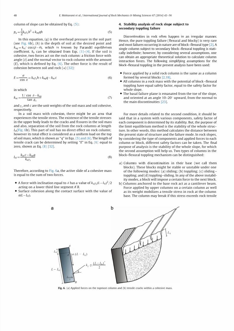
7232019 Slope Stability 201312020
httpslidepdfcomreaderfullslope-stability-201312020 614
column of slope can be obtained by Eq (5)
pa frac1412
kaγ sh2
thornkaqqh eth5THORN
In this equation (q) is the overhead pressure in the soil part(see Fig 6b) (h) is the depth of soil at the desired point andkaq frac14 ka= cos eth β θ THORN which is known by Parandtl equilibriumcoef 1047297cient ka can be obtained from Eqs (1)ndash(4) If the soil iscohesive two forces act on the rock column a friction force withangle (δ ) and the normal vector to rock column with the amount(E ) which is de1047297ned by Eq (6) The other force is the result of cohesion between soil and rock (α ) [32]
E frac14 s
cos δ frac14 kaγ sh thorn kaqq kac c eth6THORN
in which
kac frac141= cos δ kaq
tan ϕs
eth7THORN
and γ s and c are the unit weights of the soil mass and soil cohesiverespectively
In a soil mass with cohesion there might be an area thatexperiences the tensile stress The existence of the tensile stressesin the upper body leads to the cracks and 1047297ssures in the soil massand also separation of the soil from the rock columns at lengthL0(Fig 6b) This part of soil has no direct effect on rock columnhowever its total effect is considered as a uniform load on the topof soil mass which is shown as ldquoqrdquo in Eqs (5) and (6) The length of tensile crack can be determined by setting ldquoE rdquo in Eq (6) equal tozero shown as Eq (8) [32]
L0 frac14kac c kaqq
kaγ seth8THORN
Therefore according to Fig 6a the active slide of a cohesive mass
is equal to the sum of two forces
A force with inclination equal to δ has a value of kaγ sethL L0THORN2=2acting on a lower third line segment A 0B
Surface cohesion along the contact surface with the value of aethL L0THORN
4 Stability analysis of rock slope subject to
secondary toppling failure
Discontinuities in rock often happen in an irregular mannerHence the pure toppling failure (1047298exural and blocky) is very rareand most failures occurring in nature are of blockndash1047298exural type [2] Asingle column subject to secondary blockndash1047298exural toppling is stati-cally inde1047297nite however by considering several assumptions one
can obtain an appropriate theoretical solution to calculate columninteraction forces The following simplifying assumptions for theblockndash1047298exural toppling in the present analysis have been used
Force applied by a solid rock column is the same as a columnformed by several blocks [218]
All columns in a rock mass with the potential of blockndash1047298exuraltoppling have equal safety factor equal to the safety factor forwhole slope
The basal failure plane is emanated from the toe of the slopeand oriented at an angle 10ndash201 upward from the normal tothe main discontinuities [23]
For more details related to the second condition it should besaid that in a system with various components safety factor of each component is determined by its stability But the purpose of the limit equilibrium method is the stability of the whole struc-ture In other words this method calculates the distance betweenthe present state of structure and the failure mode In rock slopesby considering the type of components and applied forces to eachcolumn or block different safety factors can be taken The 1047297nalpurpose of analysis is the stability of the whole slope for whichthe second assumption will help us Two types of columns in theblockndash1047298exural toppling mechanism can be distinguished
a) Columns with discontinuities in their base (we call themblocks) These blocks might be stable or unstable under oneof the following modes (a) sliding (b) toppling (c) slidingndash
toppling and (d) topplingndashsliding In any of the above instabil-ity modes a block will impose a certain force to the next block
b) Columns anchored to the base rock act as a cantilever beamForce applied by upper columns on a certain column as wellas its weight mobilizes a tensile stress in rock at the columnbase The column may break if this stress exceeds rock tensile
L
0 L L minus
A
3
0 L L minus
A
B
)( 0 L La minus
2
)(
20 L L
k minus
γ γ
δ
0 L
Fig 6 (a) Applied forces on the topmost column and (b) tensile cracks within a cohesive mass
E Mohtarami et al International Journal of Rock Mechanics amp Mining Sciences 67 (2014) 43ndash56 48
7232019 Slope Stability 201312020
httpslidepdfcomreaderfullslope-stability-201312020 714
strength The column may also break under shear forces whichhappen if the applied loads mobilize enough shear stress onrock at column base to overcome rock shear strength
In this paper blocks and columns are generally called columnwherever their type is not important but when their type isimportant in calculation process we will call them column orblock depending on whether they are connected or not connectedat their base respectively So the blockndash1047298exural toppling is thecombination of four modes of blocky toppling sliding 1047298exuraltoppling and shearing in the rock columns
Fig 7 shows a theoretical model for the circularndashtopplingfailure In this section an analysis method is introduced for allfour modes of blockndash1047298exural toppling In this analysis any columnwithin the slope under study (say ith column) may potentially failin 1047298exural toppling or blocky toppling mode The following casesare considered in the analysis
41 Blocky toppling failure mode
Block ldquoirdquo which is presumably subject to blocky toppling iseither stable or fails in the state of toppling sliding topplingndashsliding
or slidingndash
toppling Thus these four states of instability should beconsidered in the analysis The topmost block (adjacent to the soilmass) may similarly have one of these 1047297ve states however it isunder applied pressure by soil at one side which is calculated byEq (5) Limit equilibrium for the 1047297ve states are as follows
a) Pure toppling failure mode In this mode the block ldquoirdquo is notsliding but is subject to toppling The equilibrium state can beshown as follows (Fig 8a)
sum f x frac14 ma x sum f y frac14 ma y S ioN i tan ϕ p
T i 1 ffi pi 1 tan ϕd T i thorn 1 ffi pi thorn 1 tan ϕd Li frac14 minethhi hi 1THORN
(
eth9THORN
where f x is force along the ldquo xrdquo f y is force along the ldquo yrdquo m is
rock column mass a x is acceleration components along ldquo xrdquo a y
is acceleration components along ldquo yrdquo pi thorn 1 is normal force appliedby column ldquoithorn1rdquo on column ldquoirdquo pi 1 is normal force appliedby column ldquoi1rdquo on column ldquoirdquo T i thorn 1 is shear force applied bycolumn ldquoithorn1rdquo on column ldquoirdquo T i 1 is shear force applied bycolumn ldquoi-1rdquo on column ldquoirdquo N is the normal force at the base of column S is the shear force at the base of column ϕ p is frictionangle between block and underneath rock ϕd is friction anglealong the column interfaces Li is distance between pi 1 andfailure plane (see Fig 8) and hi is height of column i
By substituting all the forces in the above dynamic equilibriumequations for intermediate blocks (i frac14 1 to i frac14 n1) and topmostblock ethi frac14 nTHORN in directions of ldquo xrdquo and ldquo yrdquo and rotational dynamicequilibrium it can be rewritten as followsFor intermediate blocks (IB) or 8 i A IB
aTHORN w i
g ai
x frac14 wi sin ψ thorn pi thorn 1 thorn V thorni pi 1 V i S i thornc ewi cos β e
bTHORN w i
g ai
y frac14 wi cos ψ thorn T i thorn 1 T i 1 N i V i c ewi sin β e
cTHORN w i
g
t 2i thorn h
2i
3 aiθ frac14 wi sin ψ hi
2 thorn c ewi cos β ehi
2 thorn N iei
thorn pi thorn 1M i pi 1Li thornV thorn
i yi
3 T i thorn 1t i V i z i
3
ethwi cos ψ c ewi sin β eTHORNt i2 thorn
γ wt 2i
6 cos ψ eth z i thorn2 yiTHORN
8gtgtgtgtgtgtgtgtgtgtltgtgtgtgtgtgtgtgtgtgt
eth10THORN
For topmost block (TB) or 8 i A
TBaTHORN w i
g ai
x frac14 wi sin ψ thorn pns thorn V thorni pi 1 V i S i thorn c ewi cos β e
bTHORN w i
g ai
y frac14 wi cos ψ thorn pns tan δ thorn ps
s thorn pc s T i 1 N i V i c ewi sin β e
cTHORN w i
g
t 2i thorn h2
i
3 aiθ frac14 wi sin ψ hi
2 thorn c ewi cos β ehi
2 thorn N iei thorn pns M i
pi 1Li thornV thorn
i yi
3 ethwi cos ψ c ewi sin β eTHORNt i2
eth pss thorn pc
s thorn pns tan δ THORNt i
V i z i3 thorn
γ wt 2i
6 cos ψ eth z i thorn2 yiTHORN
8gtgtgtgtgtgtgtgtgtgtltgtgtgtgtgtgtgtgtgtgt
eth11THORN
where pns is vertical component of load applied by soil on rock
mass pss is tangential component of load applied by soil on rock
mass pc s is shear force on contact plane of soil and topmost
column wi is weight of column I g is acceleration of gravity a x is
component of acceleration acting on column ldquoirdquo
along the X axis
β
H
sψ
1 K
Ωα
iM
p1minusi
bt
t f
i
i - 1
L i
i - 1
iiT 1+
p1+i
i
11
minusminusiiT
1minusi
i
Fig 7 Model for investigating blockyndash1047298exural toppling failure when blocks with potential of blocky and 1047298exural toppling located the alternating binary consecutive
E Mohtarami et al International Journal of Rock Mechanics amp Mining Sciences 67 (2014) 43ndash56 49
7232019 Slope Stability 201312020
httpslidepdfcomreaderfullslope-stability-201312020 814
a y is component of acceleration acting on column ldquoirdquo along the Y
axis ai
θ angular acceleration acting on column i γ
w is unit weight
of the water yi is water level in the upstream (US) of ith column z i is water level in the downstream (DS) of ith column V thorni iswater pressure at US V
i is water pressure at DS V i is uniformwater pressure at base t i is thickness of ith rock columnregardless of its type (t b and t f for blocky and 1047298exural modesrespectively) ei is distance of applying load point at the base of column ldquoirdquo to its lower edge M i is distance between pi thorn 1 andfailure plane (see Fig 8) ψ is inclination of block base plane c e isseismic coef 1047297cient and β e is deviation angle of the seismic forcefrom the X axisConsidering ai
x frac14 ai y frac14 0 and e frac14 0 for Eqs (10a) (10b) (11a) and
(11b) and solving them for pt i 1 ie the required force for
preventing failure of block ldquoirdquo lead to the following 1047297nal results
pt i 1 frac14 pi thorn 1M i pi thorn 1
tan ϕd
F s t b thorn wi sin ψ hi
2 wi cos ψ t b
2 thorn c ewi cos β e
thorn c ewi sin β e thornV thorn
i yi
3 thornγ wt 2
b
6 cos ψ eth z i thorn2 yiTHORN V i z i
3
24 35
L 1i 8 iAIB eth12aTHORN
pt i 1 frac14
wieth sin ψ thornc e cos β eTHORNhi
2 wieth cos ψ c e sin β eTHORNt b2 thorn pn
s M i pns
tan δ F s
t b
eth pss thorn pc
s THORNt b thornV thorn
i yi
3 thornγ wt 2
b6 cos ψ eth z i thorn2 yiTHORN V i
z i3
24
35
L 1i 8 iATB eth12bTHORN
where F s is factor of safety pss and pn
s are projections of active soilforce parallel and perpendicular to block respectively pc
s is theshear force along the block contact plane Fig 9 shows theseforces clearly M i measures the distance from the failure plane tothe point of acting pi 1 The force pi 1 is applied at the middle of
block ldquoithorn1rdquo
if the block ldquoithorn1rdquo
is sliding shearing or slidingndash
toppling (Fig 10a) If the block ldquoithorn1rdquo fails in pure toppling1047298exural toppling and topplingndashsliding the position of application of force ldquo pi thorn 1rdquo can be given in a general form as inEq (13) [21]
M i frac14 λhi eth13THORN
Laboratory model tests employed by Aydan et al show that thevalue of λ should be 075 to 1 [21] According to results of theirstudies it is advisable to assume λ frac14 1 which is obviously aconservative approach and is considered in this paper(Fig 10b) pi thorn 1 acts on one third of block height from the bottomto the topmost block as soil pressure
b) Sliding failure mode In this mode ith block has only slidingpotential without blocky toppling potential Equilibrium equa-tions and some simplifying assumptions can be as follows
T i thorn 1 ffi pi thorn 1 tan ϕd e frac14 t b=2
T i 1 ffi pi 1 tan ϕd Li frac14 hi=2
S i frac14 N i tan ϕ p a x frac14 a y frac14 0
8gtlt
gteth14THORN
By considering Eqs (10) and (11) and solving equilibriumequations ps
i 1 can be calculated as follows
psi 1 frac14 pi thorn 1 thorn wi eth cos ψ c e sin β eTHORN
tan ϕ p
F s sin ψ c e cos β e
h inthornV thorni thornV i
tan ϕ p
F sV i
o 1
tan ϕ p
F stan ϕd
1
8 iAIB
eth15aTHORN
psi 1 frac14
wi sin ψ cos ψ tan ϕ p
F sthorn c e cos β e thorn sin β e
tan ϕ p
F s
h ithorn pn
s 1 tan δ tan ϕ p
F s
eth ps
s thorn pc s THORN
tan ϕ p
F sthornV thorni thorn V i
tan ϕ p
F sV i
8gtltgt
9gt=gt
1 tan ϕ p
F stan ϕd
1
8 iATB eth15bTHORN
1+i
piminus1
1+iT
1minusiT a i M
L a i
p1+i
p1minusi
1+iT
1minusiT a i M
L a i
i
i
t b t f
βegt 0
βelt 0
Fig 8 (a) Force on a single block with potential of blocky toppling failure and (b) force on a column with the potential of 1047298exural toppling failure
p s
n
c p s
s p s
total psoil
Fig 9 Forces act on the topmost rock column due to active landslide of soil mass
E Mohtarami et al International Journal of Rock Mechanics amp Mining Sciences 67 (2014) 43ndash56 50
7232019 Slope Stability 201312020
httpslidepdfcomreaderfullslope-stability-201312020 914
If pt i 1 and ps
i 1 are both positive for a block which showsinstability the block should be further examined for possibletopplingndashsliding and slidingndashtoppling failure These two statesare explained in the next sections
c) Toppling ndashsliding failure mode If pi 1 t 40 pi 1 s40 and pi 1 t 4 pi 1 t the failure happens in topplingndashsliding modeBy solving Eqs(10) and (11) and using assumptions in (16) pts
i 1 it can be calculated for intermediate blocks and thetopmost one as follows
S i frac14 N i tan ϕ p T i thorn 1 ffi pi thorn 1 tan ϕd T i 1 ffi pi 1 tan ϕd
ei frac14 0 ai x frac14 ai
θ hi
2 ai y frac14 ai
θ t b2 ai
θ Z0
(
eth16THORN
ptsi 1 frac14
1k
wifrac12eth sin ψ thorn c e cos β eTHORNeth4t 2b thornh2i 3hit b tan ϕ pTHORN
thorn eth cos ψ thornc e sin β eTHORNeth tan ϕ peth4h2i thornt 2bTHORN 3hit bTHORN
thorn1k pi thorn 1
eth4t 2b thorn4h
2i 6M ihi 6M it b tan ϕ pTHORN
thorn tan ϕd
F seth tan ϕ peth2t 2b 4h
2i THORN thorn6hit bTHORN
thorn1k
h2i 4ethV thorni V i thornV i tan ϕ pTHORN
2hi
ethV thorni yi V i z iTHORN
thorn1k
t 2b 4ethV thorni V i thornV i tan ϕ pTHORN
2 tan ϕ p
t bethV thorni yi V i z iTHORN
γ w cos ψ eth z i thorn2 yiTHORNetht b tan ϕ p thorn hiTHORN
8 iAIB eth17aTHORN
ptsi 1 frac14
1k
wi eth sin ψ thornc e cos β eTHORNeth4t 2b thorn h2i 3hit b tan ϕ pTHORN
hthorn eth cos ψ thornc e sin β eTHORNeth tan ϕ peth4h
2i thornt 2bTHORN 3hit bTHORN
ithorn
1k pn
s 4t 2b thorn4h2i thorn
tan δ
F seth tan ϕ peth2t 2b 4h
2i THORN thorn6t bhiTHORN
6M iethhi thorn t b tan ϕ pTHORN
thorn1
k
eth pss thorn pc
s THORN 6t betht b tan ϕ p thornhiTHORN 4 tan ϕ pethh2i thornt 2bTHORNh i
thorn1k
t 2b 4ethV thorni V i thornV i tan ϕ pTHORN 2 tan ϕ p
t bethV thorn
i yw V i z wTHORN
γ w cos ψ eth z w thorn2 ywTHORNetht b tan ϕ p thorn hiTHORN
thorn1k
h2i 4ethV thorni V i thorn V i tan ϕ pTHORN
2hi
ethV thorni yw V i z wTHORN
8 iATB
eth17bTHORNwhere k is
k frac14 eth4etht 2b thorn h2i THORN 6LihiTHORN tan ϕ peth6Lit b thorn4
tan ϕd
F setht 2b thornh
2i THORNTHORN
Similar to the previous cases M i and Li depend on the type of failure of the two blocks the block under examination ldquoirdquo andthe upper block ldquoithorn1rdquo Finally after calculating p ts
i 1 we mayhave one of the following states
ptsi 1o 0 Pure toppling
ptsi 1 0 Transfer from toppling mode to combined mode
ptsi 14 0 TopplingSliding
8gtltgt
d) Sliding ndashtoppling failure mode If pt i 1 and ps
i 1 are bothpositive and p t
i 1 o psi 1 the failure happens in sliding-toppling
mode By considering the dynamic equilibrium equations in (10)and (11) and using assumptions in (18) pst
i 1 can be calculated forintermediate blocks and the topmost block as follows
S i frac14 N i tan ϕ p T i thorn 1 ffi pi thorn 1 tan ϕd T i 1 ffi pi 1 tan ϕd
ei frac14 0 ai xZ0 ai
y frac14 0 aiθ frac14 0
8lt eth18THORN
pst i 1 frac14
pi thorn 1tan ϕ p
F stan ϕd 1
hi
2 t b tan ϕd thornM i
h ithorn wi cos ψ
tan ϕ p
F shi
2 t b2
thorn c e sin β e
t b2 hi
2tan ϕ p
F s
h i hi
2 V thorni thorn V itan ϕ p
F s V i
h ithorn
V thorni yi
3 V i z i
3 thornγ wt 2
b
6 cos ψ eth z i thorn2 yiTHORN
8gtgtgtgtgtltgtgtgtgtgt
9gtgtgtgtgt=gtgtgtgtgt
8 iAIB Li 1tan ϕ p
F stan ϕd
hi
2 1
eth19aTHORN
i M
p i +
1
a i M
p i + 1
i i
i + 1 i + 1
Fig10 Position of application of the normal force on block ldquo irdquo from the upper block when the upper block is (a) pure sliding shearing slidingndashtoppling type and (b) puretoppling topplingndashsliding type
E Mohtarami et al International Journal of Rock Mechanics amp Mining Sciences 67 (2014) 43ndash56 51
7232019 Slope Stability 201312020
httpslidepdfcomreaderfullslope-stability-201312020 1014
pst i 1 frac14
pns
tan ϕ p
F stan δ 1
hi
2 t b tan δ thorn M i
h ithornwi cos ψ
tan ϕ p
F s
hi
2 t b2
thornc e sin β e
t b2 hi
2tan ϕ p
F s
h i hi
2 eth pss thorn pc
s THORN tan ϕ p V thorni V itan ϕ p
F sthorn V i
h i
eth pss thorn pc s THORNt b thornV thorn
i
yi
3 V
i
z i3 thorn
γ w t 2
b6 cos ψ eth z i thorn2 yiTHORN
8gtgtgtgtgtgtgtgtlt
gtgtgtgtgtgtgtgt
9gtgtgtgtgtgtgtgt=
gtgtgtgtgtgtgtgt Li 1
tan ϕ p
F stan ϕd
hi
2
1
8 iATB eth19bTHORN
In this case M i and Li are determined as in the previous casesStability determination or the type of possible instability in thecalculated block is done as follows
pst i 1 0 Only sliding
pst i 1 0 Transfer from sliding mode to the slidingtoppling
pst i 14 0 SlidingToppling
8gtltgt
e) Stable mode When psi 1 pt
i 1 o 0 the block is stable In this
case there is no need to calculate ptsi 1 and p
st i 1 Also pi 1 is
assumed to be zero in the subsequent calculation for other blocksIf this condition happens for the topmost block the soil mass hasno effect on the blocks system In this case the secondary topplingis not a probable mode of failure However any other topplingmode may still happen
42 Flexural toppling mode
If block ldquoirdquo is connected to the rock at the base of the slopeforming a cantilever position (Fig 8b) it shows tensile strengthdue to the bending state of loading Three modes ie 1047298exuraltoppling shearing and stable state can be expected
a) Flexural toppling mode In this mode column ldquoirdquo may fail dueto bending moment acting on the column Equilibrium equa-tions used in the previous section (Eqs (10) and (11))
can be used to analyze this state of loading The following
Is it first stagen = 0
Start
input parameters
NoYes
R e d u e F
s
u s i n g a r t i f i c i a l
b e e c o l o n y
Calculation of columnrsquos
data amp optimization of k a
F s = 1
Calculate of p i (i=0-n )
Display F s as an output
End
I n c r e a s e F
s
u s i n g a r t i f i c i a l
b e e c o l o n y
n = n+1n = n+1
Refer to algorithm shown in figure 12
Fig 11 A schematic algorithm of the computer codes process
Table 2
Input parameters which are used in the developed software
Input parameters Unit Input parameters Unit
Height of slope m Inclination of soil surface degreeAverage thickness of the layers in blocky mode m Friction angle between soil and rock mass degreeAverage thickness of the layers in 1047298exural mode m Internal soil friction angle degree
Distance between the soil mass to rock slopersquos crest m Cohesive in soil mass KNm
3
Slope angle with the horizontal degree Surface cohesive between the soil mass and rock KNm 3
Inclination of top surface of slope degree Friction angle of intact rock degreeInclination of the layers degree Tensile strength of rock mass KNm 3
Inclination of the failure plane degree Cohesive of intact rock sample KNm 3
Inclination of block base plane degree Pseudo-static seismic force coef 1047297cient ndash
Friction angle between block and underneath rock degree Deviation angle of the seismic force from x axis degreeFriction angle along the block interface degree
E Mohtarami et al International Journal of Rock Mechanics amp Mining Sciences 67 (2014) 43ndash56 52
7232019 Slope Stability 201312020
httpslidepdfcomreaderfullslope-stability-201312020 1114
assumptions are applicable
T i thorn 1 frac14 pi thorn 1 tan ϕd
T i 1 frac14 pi 1 tan ϕd
ei frac14 t f =2
ai x frac14 ai y frac14 0
8gtgtgtgtltgtgtgtgt
eth20THORN
Bending moment (M ) and axial force (N ) on the column at thebase point of the column are obtained as follows
N i frac14 wi cos ψ thornT i thorn 1 T i 1 V i c ewi sin β e eth21THORN
M frac14 wieth sin ψ thorn c e cos β eTHORNhi
2thorn pi thorn 1M i thorn
V thorni yi
3
t f
2ethT i thorn 1 thorn T i 1THORN
pi 1Li V
i z i3
V iLout eth22THORN
where Lout is the eccentric water pressure at base The total stressin the column should be calculated from both ldquoM rdquo and ldquoN rdquo as
shown in Eq (23) If the total tensile stress in rock column exceeds
the tensile rock strength st the rock breaks and the column isoverturned In equilibrium conditions the tensile stress mentionedin Eq (23) is equal to the tensile strength of rock It may berewritten as Eq (24) and safety factor of rock column against thetensile stress and hence against toppling is obtained from Eq (25)
s y frac14 t f =2t frac14
Mt f
2I i
N it f
eth23THORN
M frac142I it f
st thornN it f
eth24THORN
F s frac14 st =st f =2
y eth25THORN
By substituting ldquoM rdquo and ldquoN rdquo from Eqs (21) and (22) in Eq (24) p f t
i 1 is obtained as shown in Eq (26a) for the intermediatecolumns (IC) and in Eq (26b) for the topmost column (TC columnadjacent to soil mass) where I i is the second moment of columnldquoirdquo Similar to the previous cases Li and M i depend on failure type
of column or block ldquoirdquo
and ldquoithorn 1rdquo respectively
Block is
connected at its
bottom
Start
Initial calculations
NoYes
No
Yes No
Yes
No
Yes
Yes
No
Input parameters
Calculate of amp Calculate of amp
Calculate of Calculate of
Display output ie
and failure mode
End
Fig 12 An algorithm for calculating the ldquo pi1rdquofor column ldquoirdquo
Fig 13 (a) Overview of the slope and the Haraz road and (b) the soil part on top of the slope and partially equilibrium
E Mohtarami et al International Journal of Rock Mechanics amp Mining Sciences 67 (2014) 43ndash56 53
7232019 Slope Stability 201312020
httpslidepdfcomreaderfullslope-stability-201312020 1214
p f t i 1 frac14
pi thorn 1ethM i tan ϕdt f 2
2 tan ϕdI it 2 f
THORN
thornwihi
2 eth sin ψ thornc e cos β eTHORN thorn V iLout thornV thorni yi
3 thornV i z i
3
h i2I i
t f st
F sthorn
wi eth cos ψ c e sin β eTHORN V it f
8gtgtgtgtgtltgtgtgtgtgt
9gtgtgtgtgt=gtgtgtgtgt
tan ϕd
t f
2thornLi
2 tan ϕdI i
t 2 f
1
8 iAIC eth26aTHORN
p f t i 1 frac14
pns ethM i tan δ
t f 2THORN thornwi
hi
2 eth sin ψ thornc e cos β eTHORN
thorn V iLout thornV thorni yi
3 thornV i z i
3
h ieth ps
s thorn pc s THORN
t f 2
2I it f
st
F sthorn
wieth cos ψ c e sin β e THORN thorn pss thorn pc
s V it f
8gtgtgtgtltgtgtgtgt
9gtgtgtgt=gtgtgtgt
eth tan ϕd
t f
2thorn LiTHORN
1 8 iATC eth26bTHORN
b) Shear failure mode In this mode column ldquoirdquo may fail undershear force perpendicular to column axis The force shouldobviously overcome rock shear resistance mobilized by cohe-sive (C ) and friction (φr ) in intact rock By consideringassumptions in Eq (27) and limit equilibrium equations value
of pshi 1 for intermediate and topmost column it is obtained
from Eqs (28a) and (28b) respectively
T i thorn 1 ffi pi thorn 1 tan ϕd ei frac14 t f =2 ai x frac14 ai
y frac14 0
T i 1 ffi pi 1 tan ϕd S i frac14 N i tan ϕr thorn Ct f
(
eth27THORN
pshi 1 frac14 pi thorn 1 thorn wi eth cos ψ c e sin β eTHORN
tan ϕr
F s sin ψ c e cos β e
thorn V thorni thorn V itan ϕr
F s V i Ct f
) 8 iA IC 1
tan ϕr
F stan ϕd
1
eth28aTHORN
pshi 1 frac14 pn
s eth1 tan δ tan ϕr
F sTHORN wi eth cos ψ c e sin β eTHORN
tan ϕr
F s
sin ψ c e cos β e
8 iATC
eth pss thorn pc
s THORNtan ϕr
F sthorn V thorni thornV i
tan ϕr
F sV i Ct f
)
1 tan ϕr
F stan ϕd
1
eth28bTHORN
c) Stable mode When p f t i 1 psh
i 1r0 the column is stable and pi 1 is assumed to be zero in the subsequent calculation forother columns or blocks
5 Computer code developed for stability analysis
In the previous section a complete solution for circularndashtop-pling failure was presented To assess the overall stability of aslope with the combination of soil mass and rock columns thealgorithm shown in Fig 11 is proposed A computer code wasdeveloped using a user friend environment This algorithm wasused for slop stability evaluation and the calculation of safetyfactor Table 2 shows the input parameters The output for theintermediate stage of calculations is the forces between thecolumns ie pi 1 and pi thorn 1 for each column The 1047297nal output isthe force required to support toe column p0 and the safety factorof slope In this algorithm the coef 1047297cient of lateral earth pressurein the active mode ka is calculated using Eqs (1) to (4) for varioussoil conditions ldquoArti1047297cial bee colony optimizationrdquo algorithm wasused to optimize ka value Having found ka we calculated pi thorn 1 forthe topmost column using Eq (5) The values of pi 1 and pi thorn 1 iethe forces applied at both sides of each column are then calculatedaccording to the algorithm shown in Fig 12 and the formulationsdescribed in the previous section
53
25
45
6 7 0 m
3 1 9
2 m
77
Soil mass
Fig 14 A schematicof the slope located in Haraz
Table 3
Conducted tests in soil and rock parts
Conducted tests in rock parts Conducted tests in soil part
Test name Description Test name Description
Direct shear tests ϕfrac1428661 c jfrac14008 MPa Direct shear tests (using normal stress 5 Kgcm3) c frac14819 KNm 2 ϕfrac1427581Non-encapsulated strain s
avec frac14 14951 MPa Non-encapsulated strain sc frac142843 Kgcm 3
Dry and saturation density (Kgcm 3) γ dry frac14 262 γ sat frac14 2677 Determinat ion of speci1047297c gravity GS frac14259
Chemical testing of groundwater Water is not acidic or alkaline Chemical testing of groundwater Water is not acidic or alkalinePetrographic characteristics (dominant mineral) Quartz potassic feldspar biotite Dry and saturation density (Kgcm 3) γ dry frac14 1577 γ sat frac14 1968
Porosity and saturation percent n frac14 516 s frac14 2578 Porosity and saturation percent n frac14 391 s frac14 70Determination E and υ (21 samples) υ frac14 0239 E frac14 1607 ethGPaTHORN Determination E and υ υ frac14 036 E frac14 1250 ethKg =cm2THORN
The ultrasonic wave velocity V com frac14 3220 V sh frac14 1853 ethm=sTHORN The ultrasonic wave velocity V com frac14 1155 V sh frac14 540 ethm=sTHORN
E Mohtarami et al International Journal of Rock Mechanics amp Mining Sciences 67 (2014) 43ndash56 54
7232019 Slope Stability 201312020
httpslidepdfcomreaderfullslope-stability-201312020 1314
By 1047297nding p0 (ie p i 1 for toe column) the stability of a slopesubject to circular-toppling failure can be judged as follows
p04 0 Unstable
p0 frac14 0 Limit equilibrium condition
p0o 0 Stable
8gtlt
gt It should be noted that safety factor ethF sTHORN is set equal to 1 for
1047297nding p0 at the initial stage If p0 frac14 0 at the initial calculations theslope is at equilibrium state and calculation is no longer necessaryIf p040 then the slope is unstable and the value of F s is reducedgradually until p0 frac14 0 The 1047297nal calculated F s is the actual safetyfactor of the slope Similarly if p0o0 then the slope is stable Theactual safety factor is found by increasing the amount of F s incalculation loop till p0 frac14 0 The 1047297nal calculated F s is the actualsafety factor of the slope The increase or reduction of F s anddetermination of the optimum value are done using the arti1047297cialbee colony algorithm (Fig 11) In the previous studies the blockshave been alternately considered in blocky or 1047298exural topplingmode The proposed solution in this paper freely allows for anycombination
6 Case study
A real case including a slope subject to failure was studiedusing the proposed method This slope is located in Vana villagealong Haraz road in northern Iran 70 km from Amol city Theslope consists of rhyolite tuff overlooking Haraz road with thepotential of toppling Fig 13 shows the general view of the slopeand Fig 14 depicts the slope schematically As can be seen in these1047297gures a large amount of sediments and volcanic debris isdumped on the top of slope behind the rock columns This massgenerates the soil active pressure Ongoing erosion of the sedi-ments and volcanic rock not only increases the active pressure butalso causes the rock falls which have already caused some
accidents and injuries Due to the concern of possible failure of block rocks a research project was organized by research instituteof the Ministry of Roads and Urban Development for the evalua-tion of the general stability of the slope The existing residentialand commercial buildings next to this slope helped authoritiesaccept the minimum F S to be equal to 155
A number of exploration drillings were performed within theslope to obtain the geo-mechanical properties Moreover observa-tions were made through the existing tunnel of an old coal mine inthe area Table 3 shows the main obtained data used for this study
The stability of the slope in Vana village was analyzed using theproposed method and the developed code The code shows severalitems as outputs (a) Geometry and geo-mechanical parameterswhich are partially inputted by the user and partially calculated
by the code (b) forces between the columns ( pi1 and p ithorn1) and
possible failure mode of each block and (c) safety factor andstability state of the slope Furthermore we can obtain the appliedforce on topmost block by the soil by running the computer code
The analysis revealed that safety factor for this slope was equalto 164 for combined circularndashtoppling failure which was higherthan the acceptable 1047297gure by authorities The slope was found atstable state however it should be noted that due to futureerosions soil value and active soil pressure may increase during
the years Thus update evaluation may be necessary from time totime Moreover despite the general stability of this slope localrock falls can still happen Fig 15 shows potential rock falls due toerosion resulted by the running water
7 Conclusions
Different types of the toppling failure are still a major instabil-ity for slopes in nature and slopes all over the world Combinedcircularndashtoppling failure is a kind of instability not studied beforein details In this paper a complete solution was presented for thistype of failure A new formulation was developed to investigatethe stability of slope components (the soil and rock part)
The developed solution in this paper has taken all the effectiveparameters (external forces water pressure and earthquake) intoaccount Every column can be in any mode of failure including astable mode The presented solution unstable forms were widelyanalyzed from the point of limit equilibrium method in discontin-uous rock and allowed for any combination of failure in thecolumns ie failure mode of each column could be different withthe mode of neighboring columns Another advantage of theproposed solution is that the topmost column can have anyinclination and the applied force by soil mass can be calculatedby plasticity theory which has good accuracy
A computer code was developed to ease the use of the proposedsolution The code was simple and fast it gave the 1047297nal state of stability as well as safety factor of the slope By using this code the
effect of different parameters (like block inclination friction etc) onstability can be simply and quickly studied Such a study can helpthe users decide on the necessary measures for making the slopemore stable
References
[1] Goodman RE Bray JW Toppling of rock slopes In Boulder CO Proceedings of the specialty conference on rock engineering for foundations and slopesNew York American Society of Civil Engineers 15ndash18 August 1976 p 201ndash23
[2] Amini M Majdi A Veshadi MA Stability analysis of rock slopes against blockndash
1047298exure toppling failure Int J Rock Mech Rock Eng 201245(4)519ndash32[3] Collin A Recherches expeacuterimentaux sur les glissements spontaneacutes des terrains
argileux Paris Carilian-Goeurley et Dalmont [4] Taylor DW Stability of Earth slopes J Boston Soc Civ Eng 19371337ndash86
[5] Willie DC Mah CW Rock slope engineering (civil and mining) 4th EditionUK Spoon Press London Taylor and Francis Group 2004[6] Bishop AW The use of the slip circle in the stability analysis of slopes
Geacuteotechnique 195557ndash17[7] Nonveiller E The stability analysis of slopes with a slide surface of general
shape Proc 6th Int Conf Soil Mech Found Eng Montreal 1965279ndash93[8] Morgenstern NR Price VE The analysis of the stability of generalised slip
surfaces Geacuteotechnique 19651579ndash93[9] Chen Z Morgenstern NR Extensions to the generalized method of slices for
stability analysis Can Geotech J 198320(1)104ndash19[10] Muller L New considerations of the Vaiont slide Felsmech Engenieurgeologie
19686(1)1ndash91[11] Ashby J Sliding and toppling modes of failure in models and jointed rock
slopes [MSc thesis] London United Kingdom London University ImperialCollege 1971
[12] Hofmann H Kinematische modellstudien zum boschungs-problem in regal-massig geklufteten medien [PhD thesis] Karlsruhe Germany University of Karlsruhe 1972
[13] De Freitas MH Watters RJ Some 1047297eld examples of toppling failure Geacuteotech-
nique 197323495ndash514
Fig 15 Erosion and destructionwithin rock section of the slope
E Mohtarami et al International Journal of Rock Mechanics amp Mining Sciences 67 (2014) 43ndash56 55
7232019 Slope Stability 201312020
httpslidepdfcomreaderfullslope-stability-201312020 1414
[14] Whyte RJA Study of progressive hanging wall caving at chambishi coppermine in Zambia using the base friction model concept [MSc thesis] LondonUnited Kingdom London University Imperial College 1973
[15] Soto CA Comparative study of slope modelling techniques for fracturedground [MSc thesis] London United Kingdom London University ImperialCollege 1974
[16] Zanbak C Design charts for rock slopes susceptible to toppling J Geotech EngASCE 19831091039ndash62
[17] Goodman R Shi G Block theory and its application to rock engineeringEnglewood Cliffs New Jersey Prentice-Hall 1985 338
[18] Aydan Ouml Shimizu Y Ichikawa Y The effective failure modes and stability of slopes
in rock mass with two discontinuity sets Rock Mech Rock Eng 198922(3)163ndash88[19] Davies JN Smith PLP Flexural toppling of siltstones during a temporary
excavation for a bridge foundation in North Devon In Hadson JA editorComprehensive rock engineering Oxford Pergamon Press 1993 p 759ndash75
[20] Zaruba Q Mencl V Engineering geology Amsterdam Elsevier 1976[21] Aydan Ouml Kawamoto T Stability of slopes and underground openings against
1047298exural toppling and their stabilization Rock Mech Rock Eng 199225(3)143ndash65[22] Adhikary DP Dyskin AV Jewell RJ Modeling of 1047298exural toppling failures of
rock slopes In Proceedings of the eighth international congress rockmechanics Tokyo 1995 p 25ndash9
[23] Adhikary DP Dyskin AV Jewell RJ Stewart DP A study of the mechanism of 1047298exural toppling failure of rock slopes Rock Mech Rock Eng 199730(2)75ndash93
[24] Adhikary DP Dyskin AV Modeling of progressive and instantaneous failure of foliated rock slopes Rock Mech Rock Eng 200740(4)349ndash62
[25] Aydan Ouml Amini M An experimental study on rock slopes against 1047298exuraltoppling failure under dynamic loading and some theoretical considerationsfor its stability assessment J Sch Mar Sci Technol 20097(2)25 ndash40
[26] Braja MD Principles of geotechnical engineering 7th edition Stamford USACengage learning 2010
[27] Lambe TW Whitman RV Soil mechanics Massachusetts institute of technol-ogy Cambridge Massachusetts John Wiley and Sons 1969
[28] Caquot A Kerisel J Table for the calculation of passive pressure activepressure and bearing capacity of foundations (trans by MA Bec London)Paris Gauthier-Villars 1948
[29] Janbu N 4thEarth pressure and bearing capacity calculations by generalizedprocedure of slices Vol 2 London ICSMFE 1957 207ndash12
[30] Shields DH Tolunay AZ Passive pressure coef 1047297cients by method of slices JSMFD AS CE 197399(SM 12)S1043ndash53
[31] Sokolovski VV Statics of granular media Oxford Pergamon Press 1965 [32] Behnia K Tabatabai AM Soil mechanics 2nd Ed Tehran Tehran University
Press 1987[33] Chen WF Rosenfarb JL Limit analysis solutions of Earth pressure problems
Jpn S oc Soil Mech Found Eng 197313(4)45ndash60[34] PLAXIS V8 Finite element code for soil and rock analyses PLAXIS-3D
Reference manual Edited by Brinkgreve et al DUT The Netherlands langwwwplaxisnl2004rang
E Mohtarami et al International Journal of Rock Mechanics amp Mining Sciences 67 (2014) 43ndash56 56
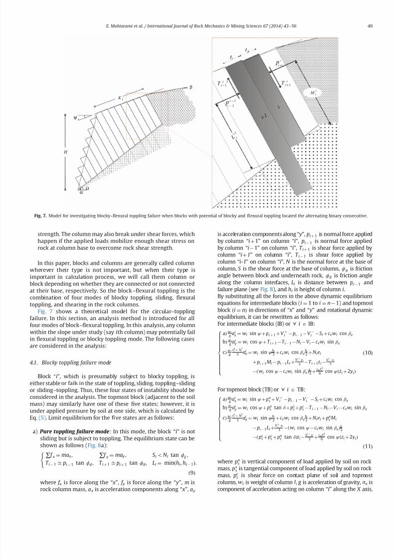
7232019 Slope Stability 201312020
httpslidepdfcomreaderfullslope-stability-201312020 714
strength The column may also break under shear forces whichhappen if the applied loads mobilize enough shear stress onrock at column base to overcome rock shear strength
In this paper blocks and columns are generally called columnwherever their type is not important but when their type isimportant in calculation process we will call them column orblock depending on whether they are connected or not connectedat their base respectively So the blockndash1047298exural toppling is thecombination of four modes of blocky toppling sliding 1047298exuraltoppling and shearing in the rock columns
Fig 7 shows a theoretical model for the circularndashtopplingfailure In this section an analysis method is introduced for allfour modes of blockndash1047298exural toppling In this analysis any columnwithin the slope under study (say ith column) may potentially failin 1047298exural toppling or blocky toppling mode The following casesare considered in the analysis
41 Blocky toppling failure mode
Block ldquoirdquo which is presumably subject to blocky toppling iseither stable or fails in the state of toppling sliding topplingndashsliding
or slidingndash
toppling Thus these four states of instability should beconsidered in the analysis The topmost block (adjacent to the soilmass) may similarly have one of these 1047297ve states however it isunder applied pressure by soil at one side which is calculated byEq (5) Limit equilibrium for the 1047297ve states are as follows
a) Pure toppling failure mode In this mode the block ldquoirdquo is notsliding but is subject to toppling The equilibrium state can beshown as follows (Fig 8a)
sum f x frac14 ma x sum f y frac14 ma y S ioN i tan ϕ p
T i 1 ffi pi 1 tan ϕd T i thorn 1 ffi pi thorn 1 tan ϕd Li frac14 minethhi hi 1THORN
(
eth9THORN
where f x is force along the ldquo xrdquo f y is force along the ldquo yrdquo m is
rock column mass a x is acceleration components along ldquo xrdquo a y
is acceleration components along ldquo yrdquo pi thorn 1 is normal force appliedby column ldquoithorn1rdquo on column ldquoirdquo pi 1 is normal force appliedby column ldquoi1rdquo on column ldquoirdquo T i thorn 1 is shear force applied bycolumn ldquoithorn1rdquo on column ldquoirdquo T i 1 is shear force applied bycolumn ldquoi-1rdquo on column ldquoirdquo N is the normal force at the base of column S is the shear force at the base of column ϕ p is frictionangle between block and underneath rock ϕd is friction anglealong the column interfaces Li is distance between pi 1 andfailure plane (see Fig 8) and hi is height of column i
By substituting all the forces in the above dynamic equilibriumequations for intermediate blocks (i frac14 1 to i frac14 n1) and topmostblock ethi frac14 nTHORN in directions of ldquo xrdquo and ldquo yrdquo and rotational dynamicequilibrium it can be rewritten as followsFor intermediate blocks (IB) or 8 i A IB
aTHORN w i
g ai
x frac14 wi sin ψ thorn pi thorn 1 thorn V thorni pi 1 V i S i thornc ewi cos β e
bTHORN w i
g ai
y frac14 wi cos ψ thorn T i thorn 1 T i 1 N i V i c ewi sin β e
cTHORN w i
g
t 2i thorn h
2i
3 aiθ frac14 wi sin ψ hi
2 thorn c ewi cos β ehi
2 thorn N iei
thorn pi thorn 1M i pi 1Li thornV thorn
i yi
3 T i thorn 1t i V i z i
3
ethwi cos ψ c ewi sin β eTHORNt i2 thorn
γ wt 2i
6 cos ψ eth z i thorn2 yiTHORN
8gtgtgtgtgtgtgtgtgtgtltgtgtgtgtgtgtgtgtgtgt
eth10THORN
For topmost block (TB) or 8 i A
TBaTHORN w i
g ai
x frac14 wi sin ψ thorn pns thorn V thorni pi 1 V i S i thorn c ewi cos β e
bTHORN w i
g ai
y frac14 wi cos ψ thorn pns tan δ thorn ps
s thorn pc s T i 1 N i V i c ewi sin β e
cTHORN w i
g
t 2i thorn h2
i
3 aiθ frac14 wi sin ψ hi
2 thorn c ewi cos β ehi
2 thorn N iei thorn pns M i
pi 1Li thornV thorn
i yi
3 ethwi cos ψ c ewi sin β eTHORNt i2
eth pss thorn pc
s thorn pns tan δ THORNt i
V i z i3 thorn
γ wt 2i
6 cos ψ eth z i thorn2 yiTHORN
8gtgtgtgtgtgtgtgtgtgtltgtgtgtgtgtgtgtgtgtgt
eth11THORN
where pns is vertical component of load applied by soil on rock
mass pss is tangential component of load applied by soil on rock
mass pc s is shear force on contact plane of soil and topmost
column wi is weight of column I g is acceleration of gravity a x is
component of acceleration acting on column ldquoirdquo
along the X axis
β
H
sψ
1 K
Ωα
iM
p1minusi
bt
t f
i
i - 1
L i
i - 1
iiT 1+
p1+i
i
11
minusminusiiT
1minusi
i
Fig 7 Model for investigating blockyndash1047298exural toppling failure when blocks with potential of blocky and 1047298exural toppling located the alternating binary consecutive
E Mohtarami et al International Journal of Rock Mechanics amp Mining Sciences 67 (2014) 43ndash56 49
7232019 Slope Stability 201312020
httpslidepdfcomreaderfullslope-stability-201312020 814
a y is component of acceleration acting on column ldquoirdquo along the Y
axis ai
θ angular acceleration acting on column i γ
w is unit weight
of the water yi is water level in the upstream (US) of ith column z i is water level in the downstream (DS) of ith column V thorni iswater pressure at US V
i is water pressure at DS V i is uniformwater pressure at base t i is thickness of ith rock columnregardless of its type (t b and t f for blocky and 1047298exural modesrespectively) ei is distance of applying load point at the base of column ldquoirdquo to its lower edge M i is distance between pi thorn 1 andfailure plane (see Fig 8) ψ is inclination of block base plane c e isseismic coef 1047297cient and β e is deviation angle of the seismic forcefrom the X axisConsidering ai
x frac14 ai y frac14 0 and e frac14 0 for Eqs (10a) (10b) (11a) and
(11b) and solving them for pt i 1 ie the required force for
preventing failure of block ldquoirdquo lead to the following 1047297nal results
pt i 1 frac14 pi thorn 1M i pi thorn 1
tan ϕd
F s t b thorn wi sin ψ hi
2 wi cos ψ t b
2 thorn c ewi cos β e
thorn c ewi sin β e thornV thorn
i yi
3 thornγ wt 2
b
6 cos ψ eth z i thorn2 yiTHORN V i z i
3
24 35
L 1i 8 iAIB eth12aTHORN
pt i 1 frac14
wieth sin ψ thornc e cos β eTHORNhi
2 wieth cos ψ c e sin β eTHORNt b2 thorn pn
s M i pns
tan δ F s
t b
eth pss thorn pc
s THORNt b thornV thorn
i yi
3 thornγ wt 2
b6 cos ψ eth z i thorn2 yiTHORN V i
z i3
24
35
L 1i 8 iATB eth12bTHORN
where F s is factor of safety pss and pn
s are projections of active soilforce parallel and perpendicular to block respectively pc
s is theshear force along the block contact plane Fig 9 shows theseforces clearly M i measures the distance from the failure plane tothe point of acting pi 1 The force pi 1 is applied at the middle of
block ldquoithorn1rdquo
if the block ldquoithorn1rdquo
is sliding shearing or slidingndash
toppling (Fig 10a) If the block ldquoithorn1rdquo fails in pure toppling1047298exural toppling and topplingndashsliding the position of application of force ldquo pi thorn 1rdquo can be given in a general form as inEq (13) [21]
M i frac14 λhi eth13THORN
Laboratory model tests employed by Aydan et al show that thevalue of λ should be 075 to 1 [21] According to results of theirstudies it is advisable to assume λ frac14 1 which is obviously aconservative approach and is considered in this paper(Fig 10b) pi thorn 1 acts on one third of block height from the bottomto the topmost block as soil pressure
b) Sliding failure mode In this mode ith block has only slidingpotential without blocky toppling potential Equilibrium equa-tions and some simplifying assumptions can be as follows
T i thorn 1 ffi pi thorn 1 tan ϕd e frac14 t b=2
T i 1 ffi pi 1 tan ϕd Li frac14 hi=2
S i frac14 N i tan ϕ p a x frac14 a y frac14 0
8gtlt
gteth14THORN
By considering Eqs (10) and (11) and solving equilibriumequations ps
i 1 can be calculated as follows
psi 1 frac14 pi thorn 1 thorn wi eth cos ψ c e sin β eTHORN
tan ϕ p
F s sin ψ c e cos β e
h inthornV thorni thornV i
tan ϕ p
F sV i
o 1
tan ϕ p
F stan ϕd
1
8 iAIB
eth15aTHORN
psi 1 frac14
wi sin ψ cos ψ tan ϕ p
F sthorn c e cos β e thorn sin β e
tan ϕ p
F s
h ithorn pn
s 1 tan δ tan ϕ p
F s
eth ps
s thorn pc s THORN
tan ϕ p
F sthornV thorni thorn V i
tan ϕ p
F sV i
8gtltgt
9gt=gt
1 tan ϕ p
F stan ϕd
1
8 iATB eth15bTHORN
1+i
piminus1
1+iT
1minusiT a i M
L a i
p1+i
p1minusi
1+iT
1minusiT a i M
L a i
i
i
t b t f
βegt 0
βelt 0
Fig 8 (a) Force on a single block with potential of blocky toppling failure and (b) force on a column with the potential of 1047298exural toppling failure
p s
n
c p s
s p s
total psoil
Fig 9 Forces act on the topmost rock column due to active landslide of soil mass
E Mohtarami et al International Journal of Rock Mechanics amp Mining Sciences 67 (2014) 43ndash56 50
7232019 Slope Stability 201312020
httpslidepdfcomreaderfullslope-stability-201312020 914
If pt i 1 and ps
i 1 are both positive for a block which showsinstability the block should be further examined for possibletopplingndashsliding and slidingndashtoppling failure These two statesare explained in the next sections
c) Toppling ndashsliding failure mode If pi 1 t 40 pi 1 s40 and pi 1 t 4 pi 1 t the failure happens in topplingndashsliding modeBy solving Eqs(10) and (11) and using assumptions in (16) pts
i 1 it can be calculated for intermediate blocks and thetopmost one as follows
S i frac14 N i tan ϕ p T i thorn 1 ffi pi thorn 1 tan ϕd T i 1 ffi pi 1 tan ϕd
ei frac14 0 ai x frac14 ai
θ hi
2 ai y frac14 ai
θ t b2 ai
θ Z0
(
eth16THORN
ptsi 1 frac14
1k
wifrac12eth sin ψ thorn c e cos β eTHORNeth4t 2b thornh2i 3hit b tan ϕ pTHORN
thorn eth cos ψ thornc e sin β eTHORNeth tan ϕ peth4h2i thornt 2bTHORN 3hit bTHORN
thorn1k pi thorn 1
eth4t 2b thorn4h
2i 6M ihi 6M it b tan ϕ pTHORN
thorn tan ϕd
F seth tan ϕ peth2t 2b 4h
2i THORN thorn6hit bTHORN
thorn1k
h2i 4ethV thorni V i thornV i tan ϕ pTHORN
2hi
ethV thorni yi V i z iTHORN
thorn1k
t 2b 4ethV thorni V i thornV i tan ϕ pTHORN
2 tan ϕ p
t bethV thorni yi V i z iTHORN
γ w cos ψ eth z i thorn2 yiTHORNetht b tan ϕ p thorn hiTHORN
8 iAIB eth17aTHORN
ptsi 1 frac14
1k
wi eth sin ψ thornc e cos β eTHORNeth4t 2b thorn h2i 3hit b tan ϕ pTHORN
hthorn eth cos ψ thornc e sin β eTHORNeth tan ϕ peth4h
2i thornt 2bTHORN 3hit bTHORN
ithorn
1k pn
s 4t 2b thorn4h2i thorn
tan δ
F seth tan ϕ peth2t 2b 4h
2i THORN thorn6t bhiTHORN
6M iethhi thorn t b tan ϕ pTHORN
thorn1
k
eth pss thorn pc
s THORN 6t betht b tan ϕ p thornhiTHORN 4 tan ϕ pethh2i thornt 2bTHORNh i
thorn1k
t 2b 4ethV thorni V i thornV i tan ϕ pTHORN 2 tan ϕ p
t bethV thorn
i yw V i z wTHORN
γ w cos ψ eth z w thorn2 ywTHORNetht b tan ϕ p thorn hiTHORN
thorn1k
h2i 4ethV thorni V i thorn V i tan ϕ pTHORN
2hi
ethV thorni yw V i z wTHORN
8 iATB
eth17bTHORNwhere k is
k frac14 eth4etht 2b thorn h2i THORN 6LihiTHORN tan ϕ peth6Lit b thorn4
tan ϕd
F setht 2b thornh
2i THORNTHORN
Similar to the previous cases M i and Li depend on the type of failure of the two blocks the block under examination ldquoirdquo andthe upper block ldquoithorn1rdquo Finally after calculating p ts
i 1 we mayhave one of the following states
ptsi 1o 0 Pure toppling
ptsi 1 0 Transfer from toppling mode to combined mode
ptsi 14 0 TopplingSliding
8gtltgt
d) Sliding ndashtoppling failure mode If pt i 1 and ps
i 1 are bothpositive and p t
i 1 o psi 1 the failure happens in sliding-toppling
mode By considering the dynamic equilibrium equations in (10)and (11) and using assumptions in (18) pst
i 1 can be calculated forintermediate blocks and the topmost block as follows
S i frac14 N i tan ϕ p T i thorn 1 ffi pi thorn 1 tan ϕd T i 1 ffi pi 1 tan ϕd
ei frac14 0 ai xZ0 ai
y frac14 0 aiθ frac14 0
8lt eth18THORN
pst i 1 frac14
pi thorn 1tan ϕ p
F stan ϕd 1
hi
2 t b tan ϕd thornM i
h ithorn wi cos ψ
tan ϕ p
F shi
2 t b2
thorn c e sin β e
t b2 hi
2tan ϕ p
F s
h i hi
2 V thorni thorn V itan ϕ p
F s V i
h ithorn
V thorni yi
3 V i z i
3 thornγ wt 2
b
6 cos ψ eth z i thorn2 yiTHORN
8gtgtgtgtgtltgtgtgtgtgt
9gtgtgtgtgt=gtgtgtgtgt
8 iAIB Li 1tan ϕ p
F stan ϕd
hi
2 1
eth19aTHORN
i M
p i +
1
a i M
p i + 1
i i
i + 1 i + 1
Fig10 Position of application of the normal force on block ldquo irdquo from the upper block when the upper block is (a) pure sliding shearing slidingndashtoppling type and (b) puretoppling topplingndashsliding type
E Mohtarami et al International Journal of Rock Mechanics amp Mining Sciences 67 (2014) 43ndash56 51
7232019 Slope Stability 201312020
httpslidepdfcomreaderfullslope-stability-201312020 1014
pst i 1 frac14
pns
tan ϕ p
F stan δ 1
hi
2 t b tan δ thorn M i
h ithornwi cos ψ
tan ϕ p
F s
hi
2 t b2
thornc e sin β e
t b2 hi
2tan ϕ p
F s
h i hi
2 eth pss thorn pc
s THORN tan ϕ p V thorni V itan ϕ p
F sthorn V i
h i
eth pss thorn pc s THORNt b thornV thorn
i
yi
3 V
i
z i3 thorn
γ w t 2
b6 cos ψ eth z i thorn2 yiTHORN
8gtgtgtgtgtgtgtgtlt
gtgtgtgtgtgtgtgt
9gtgtgtgtgtgtgtgt=
gtgtgtgtgtgtgtgt Li 1
tan ϕ p
F stan ϕd
hi
2
1
8 iATB eth19bTHORN
In this case M i and Li are determined as in the previous casesStability determination or the type of possible instability in thecalculated block is done as follows
pst i 1 0 Only sliding
pst i 1 0 Transfer from sliding mode to the slidingtoppling
pst i 14 0 SlidingToppling
8gtltgt
e) Stable mode When psi 1 pt
i 1 o 0 the block is stable In this
case there is no need to calculate ptsi 1 and p
st i 1 Also pi 1 is
assumed to be zero in the subsequent calculation for other blocksIf this condition happens for the topmost block the soil mass hasno effect on the blocks system In this case the secondary topplingis not a probable mode of failure However any other topplingmode may still happen
42 Flexural toppling mode
If block ldquoirdquo is connected to the rock at the base of the slopeforming a cantilever position (Fig 8b) it shows tensile strengthdue to the bending state of loading Three modes ie 1047298exuraltoppling shearing and stable state can be expected
a) Flexural toppling mode In this mode column ldquoirdquo may fail dueto bending moment acting on the column Equilibrium equa-tions used in the previous section (Eqs (10) and (11))
can be used to analyze this state of loading The following
Is it first stagen = 0
Start
input parameters
NoYes
R e d u e F
s
u s i n g a r t i f i c i a l
b e e c o l o n y
Calculation of columnrsquos
data amp optimization of k a
F s = 1
Calculate of p i (i=0-n )
Display F s as an output
End
I n c r e a s e F
s
u s i n g a r t i f i c i a l
b e e c o l o n y
n = n+1n = n+1
Refer to algorithm shown in figure 12
Fig 11 A schematic algorithm of the computer codes process
Table 2
Input parameters which are used in the developed software
Input parameters Unit Input parameters Unit
Height of slope m Inclination of soil surface degreeAverage thickness of the layers in blocky mode m Friction angle between soil and rock mass degreeAverage thickness of the layers in 1047298exural mode m Internal soil friction angle degree
Distance between the soil mass to rock slopersquos crest m Cohesive in soil mass KNm
3
Slope angle with the horizontal degree Surface cohesive between the soil mass and rock KNm 3
Inclination of top surface of slope degree Friction angle of intact rock degreeInclination of the layers degree Tensile strength of rock mass KNm 3
Inclination of the failure plane degree Cohesive of intact rock sample KNm 3
Inclination of block base plane degree Pseudo-static seismic force coef 1047297cient ndash
Friction angle between block and underneath rock degree Deviation angle of the seismic force from x axis degreeFriction angle along the block interface degree
E Mohtarami et al International Journal of Rock Mechanics amp Mining Sciences 67 (2014) 43ndash56 52
7232019 Slope Stability 201312020
httpslidepdfcomreaderfullslope-stability-201312020 1114
assumptions are applicable
T i thorn 1 frac14 pi thorn 1 tan ϕd
T i 1 frac14 pi 1 tan ϕd
ei frac14 t f =2
ai x frac14 ai y frac14 0
8gtgtgtgtltgtgtgtgt
eth20THORN
Bending moment (M ) and axial force (N ) on the column at thebase point of the column are obtained as follows
N i frac14 wi cos ψ thornT i thorn 1 T i 1 V i c ewi sin β e eth21THORN
M frac14 wieth sin ψ thorn c e cos β eTHORNhi
2thorn pi thorn 1M i thorn
V thorni yi
3
t f
2ethT i thorn 1 thorn T i 1THORN
pi 1Li V
i z i3
V iLout eth22THORN
where Lout is the eccentric water pressure at base The total stressin the column should be calculated from both ldquoM rdquo and ldquoN rdquo as
shown in Eq (23) If the total tensile stress in rock column exceeds
the tensile rock strength st the rock breaks and the column isoverturned In equilibrium conditions the tensile stress mentionedin Eq (23) is equal to the tensile strength of rock It may berewritten as Eq (24) and safety factor of rock column against thetensile stress and hence against toppling is obtained from Eq (25)
s y frac14 t f =2t frac14
Mt f
2I i
N it f
eth23THORN
M frac142I it f
st thornN it f
eth24THORN
F s frac14 st =st f =2
y eth25THORN
By substituting ldquoM rdquo and ldquoN rdquo from Eqs (21) and (22) in Eq (24) p f t
i 1 is obtained as shown in Eq (26a) for the intermediatecolumns (IC) and in Eq (26b) for the topmost column (TC columnadjacent to soil mass) where I i is the second moment of columnldquoirdquo Similar to the previous cases Li and M i depend on failure type
of column or block ldquoirdquo
and ldquoithorn 1rdquo respectively
Block is
connected at its
bottom
Start
Initial calculations
NoYes
No
Yes No
Yes
No
Yes
Yes
No
Input parameters
Calculate of amp Calculate of amp
Calculate of Calculate of
Display output ie
and failure mode
End
Fig 12 An algorithm for calculating the ldquo pi1rdquofor column ldquoirdquo
Fig 13 (a) Overview of the slope and the Haraz road and (b) the soil part on top of the slope and partially equilibrium
E Mohtarami et al International Journal of Rock Mechanics amp Mining Sciences 67 (2014) 43ndash56 53
7232019 Slope Stability 201312020
httpslidepdfcomreaderfullslope-stability-201312020 1214
p f t i 1 frac14
pi thorn 1ethM i tan ϕdt f 2
2 tan ϕdI it 2 f
THORN
thornwihi
2 eth sin ψ thornc e cos β eTHORN thorn V iLout thornV thorni yi
3 thornV i z i
3
h i2I i
t f st
F sthorn
wi eth cos ψ c e sin β eTHORN V it f
8gtgtgtgtgtltgtgtgtgtgt
9gtgtgtgtgt=gtgtgtgtgt
tan ϕd
t f
2thornLi
2 tan ϕdI i
t 2 f
1
8 iAIC eth26aTHORN
p f t i 1 frac14
pns ethM i tan δ
t f 2THORN thornwi
hi
2 eth sin ψ thornc e cos β eTHORN
thorn V iLout thornV thorni yi
3 thornV i z i
3
h ieth ps
s thorn pc s THORN
t f 2
2I it f
st
F sthorn
wieth cos ψ c e sin β e THORN thorn pss thorn pc
s V it f
8gtgtgtgtltgtgtgtgt
9gtgtgtgt=gtgtgtgt
eth tan ϕd
t f
2thorn LiTHORN
1 8 iATC eth26bTHORN
b) Shear failure mode In this mode column ldquoirdquo may fail undershear force perpendicular to column axis The force shouldobviously overcome rock shear resistance mobilized by cohe-sive (C ) and friction (φr ) in intact rock By consideringassumptions in Eq (27) and limit equilibrium equations value
of pshi 1 for intermediate and topmost column it is obtained
from Eqs (28a) and (28b) respectively
T i thorn 1 ffi pi thorn 1 tan ϕd ei frac14 t f =2 ai x frac14 ai
y frac14 0
T i 1 ffi pi 1 tan ϕd S i frac14 N i tan ϕr thorn Ct f
(
eth27THORN
pshi 1 frac14 pi thorn 1 thorn wi eth cos ψ c e sin β eTHORN
tan ϕr
F s sin ψ c e cos β e
thorn V thorni thorn V itan ϕr
F s V i Ct f
) 8 iA IC 1
tan ϕr
F stan ϕd
1
eth28aTHORN
pshi 1 frac14 pn
s eth1 tan δ tan ϕr
F sTHORN wi eth cos ψ c e sin β eTHORN
tan ϕr
F s
sin ψ c e cos β e
8 iATC
eth pss thorn pc
s THORNtan ϕr
F sthorn V thorni thornV i
tan ϕr
F sV i Ct f
)
1 tan ϕr
F stan ϕd
1
eth28bTHORN
c) Stable mode When p f t i 1 psh
i 1r0 the column is stable and pi 1 is assumed to be zero in the subsequent calculation forother columns or blocks
5 Computer code developed for stability analysis
In the previous section a complete solution for circularndashtop-pling failure was presented To assess the overall stability of aslope with the combination of soil mass and rock columns thealgorithm shown in Fig 11 is proposed A computer code wasdeveloped using a user friend environment This algorithm wasused for slop stability evaluation and the calculation of safetyfactor Table 2 shows the input parameters The output for theintermediate stage of calculations is the forces between thecolumns ie pi 1 and pi thorn 1 for each column The 1047297nal output isthe force required to support toe column p0 and the safety factorof slope In this algorithm the coef 1047297cient of lateral earth pressurein the active mode ka is calculated using Eqs (1) to (4) for varioussoil conditions ldquoArti1047297cial bee colony optimizationrdquo algorithm wasused to optimize ka value Having found ka we calculated pi thorn 1 forthe topmost column using Eq (5) The values of pi 1 and pi thorn 1 iethe forces applied at both sides of each column are then calculatedaccording to the algorithm shown in Fig 12 and the formulationsdescribed in the previous section
53
25
45
6 7 0 m
3 1 9
2 m
77
Soil mass
Fig 14 A schematicof the slope located in Haraz
Table 3
Conducted tests in soil and rock parts
Conducted tests in rock parts Conducted tests in soil part
Test name Description Test name Description
Direct shear tests ϕfrac1428661 c jfrac14008 MPa Direct shear tests (using normal stress 5 Kgcm3) c frac14819 KNm 2 ϕfrac1427581Non-encapsulated strain s
avec frac14 14951 MPa Non-encapsulated strain sc frac142843 Kgcm 3
Dry and saturation density (Kgcm 3) γ dry frac14 262 γ sat frac14 2677 Determinat ion of speci1047297c gravity GS frac14259
Chemical testing of groundwater Water is not acidic or alkaline Chemical testing of groundwater Water is not acidic or alkalinePetrographic characteristics (dominant mineral) Quartz potassic feldspar biotite Dry and saturation density (Kgcm 3) γ dry frac14 1577 γ sat frac14 1968
Porosity and saturation percent n frac14 516 s frac14 2578 Porosity and saturation percent n frac14 391 s frac14 70Determination E and υ (21 samples) υ frac14 0239 E frac14 1607 ethGPaTHORN Determination E and υ υ frac14 036 E frac14 1250 ethKg =cm2THORN
The ultrasonic wave velocity V com frac14 3220 V sh frac14 1853 ethm=sTHORN The ultrasonic wave velocity V com frac14 1155 V sh frac14 540 ethm=sTHORN
E Mohtarami et al International Journal of Rock Mechanics amp Mining Sciences 67 (2014) 43ndash56 54
7232019 Slope Stability 201312020
httpslidepdfcomreaderfullslope-stability-201312020 1314
By 1047297nding p0 (ie p i 1 for toe column) the stability of a slopesubject to circular-toppling failure can be judged as follows
p04 0 Unstable
p0 frac14 0 Limit equilibrium condition
p0o 0 Stable
8gtlt
gt It should be noted that safety factor ethF sTHORN is set equal to 1 for
1047297nding p0 at the initial stage If p0 frac14 0 at the initial calculations theslope is at equilibrium state and calculation is no longer necessaryIf p040 then the slope is unstable and the value of F s is reducedgradually until p0 frac14 0 The 1047297nal calculated F s is the actual safetyfactor of the slope Similarly if p0o0 then the slope is stable Theactual safety factor is found by increasing the amount of F s incalculation loop till p0 frac14 0 The 1047297nal calculated F s is the actualsafety factor of the slope The increase or reduction of F s anddetermination of the optimum value are done using the arti1047297cialbee colony algorithm (Fig 11) In the previous studies the blockshave been alternately considered in blocky or 1047298exural topplingmode The proposed solution in this paper freely allows for anycombination
6 Case study
A real case including a slope subject to failure was studiedusing the proposed method This slope is located in Vana villagealong Haraz road in northern Iran 70 km from Amol city Theslope consists of rhyolite tuff overlooking Haraz road with thepotential of toppling Fig 13 shows the general view of the slopeand Fig 14 depicts the slope schematically As can be seen in these1047297gures a large amount of sediments and volcanic debris isdumped on the top of slope behind the rock columns This massgenerates the soil active pressure Ongoing erosion of the sedi-ments and volcanic rock not only increases the active pressure butalso causes the rock falls which have already caused some
accidents and injuries Due to the concern of possible failure of block rocks a research project was organized by research instituteof the Ministry of Roads and Urban Development for the evalua-tion of the general stability of the slope The existing residentialand commercial buildings next to this slope helped authoritiesaccept the minimum F S to be equal to 155
A number of exploration drillings were performed within theslope to obtain the geo-mechanical properties Moreover observa-tions were made through the existing tunnel of an old coal mine inthe area Table 3 shows the main obtained data used for this study
The stability of the slope in Vana village was analyzed using theproposed method and the developed code The code shows severalitems as outputs (a) Geometry and geo-mechanical parameterswhich are partially inputted by the user and partially calculated
by the code (b) forces between the columns ( pi1 and p ithorn1) and
possible failure mode of each block and (c) safety factor andstability state of the slope Furthermore we can obtain the appliedforce on topmost block by the soil by running the computer code
The analysis revealed that safety factor for this slope was equalto 164 for combined circularndashtoppling failure which was higherthan the acceptable 1047297gure by authorities The slope was found atstable state however it should be noted that due to futureerosions soil value and active soil pressure may increase during
the years Thus update evaluation may be necessary from time totime Moreover despite the general stability of this slope localrock falls can still happen Fig 15 shows potential rock falls due toerosion resulted by the running water
7 Conclusions
Different types of the toppling failure are still a major instabil-ity for slopes in nature and slopes all over the world Combinedcircularndashtoppling failure is a kind of instability not studied beforein details In this paper a complete solution was presented for thistype of failure A new formulation was developed to investigatethe stability of slope components (the soil and rock part)
The developed solution in this paper has taken all the effectiveparameters (external forces water pressure and earthquake) intoaccount Every column can be in any mode of failure including astable mode The presented solution unstable forms were widelyanalyzed from the point of limit equilibrium method in discontin-uous rock and allowed for any combination of failure in thecolumns ie failure mode of each column could be different withthe mode of neighboring columns Another advantage of theproposed solution is that the topmost column can have anyinclination and the applied force by soil mass can be calculatedby plasticity theory which has good accuracy
A computer code was developed to ease the use of the proposedsolution The code was simple and fast it gave the 1047297nal state of stability as well as safety factor of the slope By using this code the
effect of different parameters (like block inclination friction etc) onstability can be simply and quickly studied Such a study can helpthe users decide on the necessary measures for making the slopemore stable
References
[1] Goodman RE Bray JW Toppling of rock slopes In Boulder CO Proceedings of the specialty conference on rock engineering for foundations and slopesNew York American Society of Civil Engineers 15ndash18 August 1976 p 201ndash23
[2] Amini M Majdi A Veshadi MA Stability analysis of rock slopes against blockndash
1047298exure toppling failure Int J Rock Mech Rock Eng 201245(4)519ndash32[3] Collin A Recherches expeacuterimentaux sur les glissements spontaneacutes des terrains
argileux Paris Carilian-Goeurley et Dalmont [4] Taylor DW Stability of Earth slopes J Boston Soc Civ Eng 19371337ndash86
[5] Willie DC Mah CW Rock slope engineering (civil and mining) 4th EditionUK Spoon Press London Taylor and Francis Group 2004[6] Bishop AW The use of the slip circle in the stability analysis of slopes
Geacuteotechnique 195557ndash17[7] Nonveiller E The stability analysis of slopes with a slide surface of general
shape Proc 6th Int Conf Soil Mech Found Eng Montreal 1965279ndash93[8] Morgenstern NR Price VE The analysis of the stability of generalised slip
surfaces Geacuteotechnique 19651579ndash93[9] Chen Z Morgenstern NR Extensions to the generalized method of slices for
stability analysis Can Geotech J 198320(1)104ndash19[10] Muller L New considerations of the Vaiont slide Felsmech Engenieurgeologie
19686(1)1ndash91[11] Ashby J Sliding and toppling modes of failure in models and jointed rock
slopes [MSc thesis] London United Kingdom London University ImperialCollege 1971
[12] Hofmann H Kinematische modellstudien zum boschungs-problem in regal-massig geklufteten medien [PhD thesis] Karlsruhe Germany University of Karlsruhe 1972
[13] De Freitas MH Watters RJ Some 1047297eld examples of toppling failure Geacuteotech-
nique 197323495ndash514
Fig 15 Erosion and destructionwithin rock section of the slope
E Mohtarami et al International Journal of Rock Mechanics amp Mining Sciences 67 (2014) 43ndash56 55
7232019 Slope Stability 201312020
httpslidepdfcomreaderfullslope-stability-201312020 1414
[14] Whyte RJA Study of progressive hanging wall caving at chambishi coppermine in Zambia using the base friction model concept [MSc thesis] LondonUnited Kingdom London University Imperial College 1973
[15] Soto CA Comparative study of slope modelling techniques for fracturedground [MSc thesis] London United Kingdom London University ImperialCollege 1974
[16] Zanbak C Design charts for rock slopes susceptible to toppling J Geotech EngASCE 19831091039ndash62
[17] Goodman R Shi G Block theory and its application to rock engineeringEnglewood Cliffs New Jersey Prentice-Hall 1985 338
[18] Aydan Ouml Shimizu Y Ichikawa Y The effective failure modes and stability of slopes
in rock mass with two discontinuity sets Rock Mech Rock Eng 198922(3)163ndash88[19] Davies JN Smith PLP Flexural toppling of siltstones during a temporary
excavation for a bridge foundation in North Devon In Hadson JA editorComprehensive rock engineering Oxford Pergamon Press 1993 p 759ndash75
[20] Zaruba Q Mencl V Engineering geology Amsterdam Elsevier 1976[21] Aydan Ouml Kawamoto T Stability of slopes and underground openings against
1047298exural toppling and their stabilization Rock Mech Rock Eng 199225(3)143ndash65[22] Adhikary DP Dyskin AV Jewell RJ Modeling of 1047298exural toppling failures of
rock slopes In Proceedings of the eighth international congress rockmechanics Tokyo 1995 p 25ndash9
[23] Adhikary DP Dyskin AV Jewell RJ Stewart DP A study of the mechanism of 1047298exural toppling failure of rock slopes Rock Mech Rock Eng 199730(2)75ndash93
[24] Adhikary DP Dyskin AV Modeling of progressive and instantaneous failure of foliated rock slopes Rock Mech Rock Eng 200740(4)349ndash62
[25] Aydan Ouml Amini M An experimental study on rock slopes against 1047298exuraltoppling failure under dynamic loading and some theoretical considerationsfor its stability assessment J Sch Mar Sci Technol 20097(2)25 ndash40
[26] Braja MD Principles of geotechnical engineering 7th edition Stamford USACengage learning 2010
[27] Lambe TW Whitman RV Soil mechanics Massachusetts institute of technol-ogy Cambridge Massachusetts John Wiley and Sons 1969
[28] Caquot A Kerisel J Table for the calculation of passive pressure activepressure and bearing capacity of foundations (trans by MA Bec London)Paris Gauthier-Villars 1948
[29] Janbu N 4thEarth pressure and bearing capacity calculations by generalizedprocedure of slices Vol 2 London ICSMFE 1957 207ndash12
[30] Shields DH Tolunay AZ Passive pressure coef 1047297cients by method of slices JSMFD AS CE 197399(SM 12)S1043ndash53
[31] Sokolovski VV Statics of granular media Oxford Pergamon Press 1965 [32] Behnia K Tabatabai AM Soil mechanics 2nd Ed Tehran Tehran University
Press 1987[33] Chen WF Rosenfarb JL Limit analysis solutions of Earth pressure problems
Jpn S oc Soil Mech Found Eng 197313(4)45ndash60[34] PLAXIS V8 Finite element code for soil and rock analyses PLAXIS-3D
Reference manual Edited by Brinkgreve et al DUT The Netherlands langwwwplaxisnl2004rang
E Mohtarami et al International Journal of Rock Mechanics amp Mining Sciences 67 (2014) 43ndash56 56
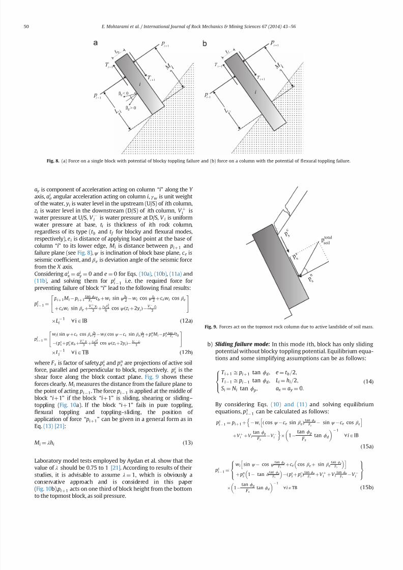
7232019 Slope Stability 201312020
httpslidepdfcomreaderfullslope-stability-201312020 814
a y is component of acceleration acting on column ldquoirdquo along the Y
axis ai
θ angular acceleration acting on column i γ
w is unit weight
of the water yi is water level in the upstream (US) of ith column z i is water level in the downstream (DS) of ith column V thorni iswater pressure at US V
i is water pressure at DS V i is uniformwater pressure at base t i is thickness of ith rock columnregardless of its type (t b and t f for blocky and 1047298exural modesrespectively) ei is distance of applying load point at the base of column ldquoirdquo to its lower edge M i is distance between pi thorn 1 andfailure plane (see Fig 8) ψ is inclination of block base plane c e isseismic coef 1047297cient and β e is deviation angle of the seismic forcefrom the X axisConsidering ai
x frac14 ai y frac14 0 and e frac14 0 for Eqs (10a) (10b) (11a) and
(11b) and solving them for pt i 1 ie the required force for
preventing failure of block ldquoirdquo lead to the following 1047297nal results
pt i 1 frac14 pi thorn 1M i pi thorn 1
tan ϕd
F s t b thorn wi sin ψ hi
2 wi cos ψ t b
2 thorn c ewi cos β e
thorn c ewi sin β e thornV thorn
i yi
3 thornγ wt 2
b
6 cos ψ eth z i thorn2 yiTHORN V i z i
3
24 35
L 1i 8 iAIB eth12aTHORN
pt i 1 frac14
wieth sin ψ thornc e cos β eTHORNhi
2 wieth cos ψ c e sin β eTHORNt b2 thorn pn
s M i pns
tan δ F s
t b
eth pss thorn pc
s THORNt b thornV thorn
i yi
3 thornγ wt 2
b6 cos ψ eth z i thorn2 yiTHORN V i
z i3
24
35
L 1i 8 iATB eth12bTHORN
where F s is factor of safety pss and pn
s are projections of active soilforce parallel and perpendicular to block respectively pc
s is theshear force along the block contact plane Fig 9 shows theseforces clearly M i measures the distance from the failure plane tothe point of acting pi 1 The force pi 1 is applied at the middle of
block ldquoithorn1rdquo
if the block ldquoithorn1rdquo
is sliding shearing or slidingndash
toppling (Fig 10a) If the block ldquoithorn1rdquo fails in pure toppling1047298exural toppling and topplingndashsliding the position of application of force ldquo pi thorn 1rdquo can be given in a general form as inEq (13) [21]
M i frac14 λhi eth13THORN
Laboratory model tests employed by Aydan et al show that thevalue of λ should be 075 to 1 [21] According to results of theirstudies it is advisable to assume λ frac14 1 which is obviously aconservative approach and is considered in this paper(Fig 10b) pi thorn 1 acts on one third of block height from the bottomto the topmost block as soil pressure
b) Sliding failure mode In this mode ith block has only slidingpotential without blocky toppling potential Equilibrium equa-tions and some simplifying assumptions can be as follows
T i thorn 1 ffi pi thorn 1 tan ϕd e frac14 t b=2
T i 1 ffi pi 1 tan ϕd Li frac14 hi=2
S i frac14 N i tan ϕ p a x frac14 a y frac14 0
8gtlt
gteth14THORN
By considering Eqs (10) and (11) and solving equilibriumequations ps
i 1 can be calculated as follows
psi 1 frac14 pi thorn 1 thorn wi eth cos ψ c e sin β eTHORN
tan ϕ p
F s sin ψ c e cos β e
h inthornV thorni thornV i
tan ϕ p
F sV i
o 1
tan ϕ p
F stan ϕd
1
8 iAIB
eth15aTHORN
psi 1 frac14
wi sin ψ cos ψ tan ϕ p
F sthorn c e cos β e thorn sin β e
tan ϕ p
F s
h ithorn pn
s 1 tan δ tan ϕ p
F s
eth ps
s thorn pc s THORN
tan ϕ p
F sthornV thorni thorn V i
tan ϕ p
F sV i
8gtltgt
9gt=gt
1 tan ϕ p
F stan ϕd
1
8 iATB eth15bTHORN
1+i
piminus1
1+iT
1minusiT a i M
L a i
p1+i
p1minusi
1+iT
1minusiT a i M
L a i
i
i
t b t f
βegt 0
βelt 0
Fig 8 (a) Force on a single block with potential of blocky toppling failure and (b) force on a column with the potential of 1047298exural toppling failure
p s
n
c p s
s p s
total psoil
Fig 9 Forces act on the topmost rock column due to active landslide of soil mass
E Mohtarami et al International Journal of Rock Mechanics amp Mining Sciences 67 (2014) 43ndash56 50
7232019 Slope Stability 201312020
httpslidepdfcomreaderfullslope-stability-201312020 914
If pt i 1 and ps
i 1 are both positive for a block which showsinstability the block should be further examined for possibletopplingndashsliding and slidingndashtoppling failure These two statesare explained in the next sections
c) Toppling ndashsliding failure mode If pi 1 t 40 pi 1 s40 and pi 1 t 4 pi 1 t the failure happens in topplingndashsliding modeBy solving Eqs(10) and (11) and using assumptions in (16) pts
i 1 it can be calculated for intermediate blocks and thetopmost one as follows
S i frac14 N i tan ϕ p T i thorn 1 ffi pi thorn 1 tan ϕd T i 1 ffi pi 1 tan ϕd
ei frac14 0 ai x frac14 ai
θ hi
2 ai y frac14 ai
θ t b2 ai
θ Z0
(
eth16THORN
ptsi 1 frac14
1k
wifrac12eth sin ψ thorn c e cos β eTHORNeth4t 2b thornh2i 3hit b tan ϕ pTHORN
thorn eth cos ψ thornc e sin β eTHORNeth tan ϕ peth4h2i thornt 2bTHORN 3hit bTHORN
thorn1k pi thorn 1
eth4t 2b thorn4h
2i 6M ihi 6M it b tan ϕ pTHORN
thorn tan ϕd
F seth tan ϕ peth2t 2b 4h
2i THORN thorn6hit bTHORN
thorn1k
h2i 4ethV thorni V i thornV i tan ϕ pTHORN
2hi
ethV thorni yi V i z iTHORN
thorn1k
t 2b 4ethV thorni V i thornV i tan ϕ pTHORN
2 tan ϕ p
t bethV thorni yi V i z iTHORN
γ w cos ψ eth z i thorn2 yiTHORNetht b tan ϕ p thorn hiTHORN
8 iAIB eth17aTHORN
ptsi 1 frac14
1k
wi eth sin ψ thornc e cos β eTHORNeth4t 2b thorn h2i 3hit b tan ϕ pTHORN
hthorn eth cos ψ thornc e sin β eTHORNeth tan ϕ peth4h
2i thornt 2bTHORN 3hit bTHORN
ithorn
1k pn
s 4t 2b thorn4h2i thorn
tan δ
F seth tan ϕ peth2t 2b 4h
2i THORN thorn6t bhiTHORN
6M iethhi thorn t b tan ϕ pTHORN
thorn1
k
eth pss thorn pc
s THORN 6t betht b tan ϕ p thornhiTHORN 4 tan ϕ pethh2i thornt 2bTHORNh i
thorn1k
t 2b 4ethV thorni V i thornV i tan ϕ pTHORN 2 tan ϕ p
t bethV thorn
i yw V i z wTHORN
γ w cos ψ eth z w thorn2 ywTHORNetht b tan ϕ p thorn hiTHORN
thorn1k
h2i 4ethV thorni V i thorn V i tan ϕ pTHORN
2hi
ethV thorni yw V i z wTHORN
8 iATB
eth17bTHORNwhere k is
k frac14 eth4etht 2b thorn h2i THORN 6LihiTHORN tan ϕ peth6Lit b thorn4
tan ϕd
F setht 2b thornh
2i THORNTHORN
Similar to the previous cases M i and Li depend on the type of failure of the two blocks the block under examination ldquoirdquo andthe upper block ldquoithorn1rdquo Finally after calculating p ts
i 1 we mayhave one of the following states
ptsi 1o 0 Pure toppling
ptsi 1 0 Transfer from toppling mode to combined mode
ptsi 14 0 TopplingSliding
8gtltgt
d) Sliding ndashtoppling failure mode If pt i 1 and ps
i 1 are bothpositive and p t
i 1 o psi 1 the failure happens in sliding-toppling
mode By considering the dynamic equilibrium equations in (10)and (11) and using assumptions in (18) pst
i 1 can be calculated forintermediate blocks and the topmost block as follows
S i frac14 N i tan ϕ p T i thorn 1 ffi pi thorn 1 tan ϕd T i 1 ffi pi 1 tan ϕd
ei frac14 0 ai xZ0 ai
y frac14 0 aiθ frac14 0
8lt eth18THORN
pst i 1 frac14
pi thorn 1tan ϕ p
F stan ϕd 1
hi
2 t b tan ϕd thornM i
h ithorn wi cos ψ
tan ϕ p
F shi
2 t b2
thorn c e sin β e
t b2 hi
2tan ϕ p
F s
h i hi
2 V thorni thorn V itan ϕ p
F s V i
h ithorn
V thorni yi
3 V i z i
3 thornγ wt 2
b
6 cos ψ eth z i thorn2 yiTHORN
8gtgtgtgtgtltgtgtgtgtgt
9gtgtgtgtgt=gtgtgtgtgt
8 iAIB Li 1tan ϕ p
F stan ϕd
hi
2 1
eth19aTHORN
i M
p i +
1
a i M
p i + 1
i i
i + 1 i + 1
Fig10 Position of application of the normal force on block ldquo irdquo from the upper block when the upper block is (a) pure sliding shearing slidingndashtoppling type and (b) puretoppling topplingndashsliding type
E Mohtarami et al International Journal of Rock Mechanics amp Mining Sciences 67 (2014) 43ndash56 51
7232019 Slope Stability 201312020
httpslidepdfcomreaderfullslope-stability-201312020 1014
pst i 1 frac14
pns
tan ϕ p
F stan δ 1
hi
2 t b tan δ thorn M i
h ithornwi cos ψ
tan ϕ p
F s
hi
2 t b2
thornc e sin β e
t b2 hi
2tan ϕ p
F s
h i hi
2 eth pss thorn pc
s THORN tan ϕ p V thorni V itan ϕ p
F sthorn V i
h i
eth pss thorn pc s THORNt b thornV thorn
i
yi
3 V
i
z i3 thorn
γ w t 2
b6 cos ψ eth z i thorn2 yiTHORN
8gtgtgtgtgtgtgtgtlt
gtgtgtgtgtgtgtgt
9gtgtgtgtgtgtgtgt=
gtgtgtgtgtgtgtgt Li 1
tan ϕ p
F stan ϕd
hi
2
1
8 iATB eth19bTHORN
In this case M i and Li are determined as in the previous casesStability determination or the type of possible instability in thecalculated block is done as follows
pst i 1 0 Only sliding
pst i 1 0 Transfer from sliding mode to the slidingtoppling
pst i 14 0 SlidingToppling
8gtltgt
e) Stable mode When psi 1 pt
i 1 o 0 the block is stable In this
case there is no need to calculate ptsi 1 and p
st i 1 Also pi 1 is
assumed to be zero in the subsequent calculation for other blocksIf this condition happens for the topmost block the soil mass hasno effect on the blocks system In this case the secondary topplingis not a probable mode of failure However any other topplingmode may still happen
42 Flexural toppling mode
If block ldquoirdquo is connected to the rock at the base of the slopeforming a cantilever position (Fig 8b) it shows tensile strengthdue to the bending state of loading Three modes ie 1047298exuraltoppling shearing and stable state can be expected
a) Flexural toppling mode In this mode column ldquoirdquo may fail dueto bending moment acting on the column Equilibrium equa-tions used in the previous section (Eqs (10) and (11))
can be used to analyze this state of loading The following
Is it first stagen = 0
Start
input parameters
NoYes
R e d u e F
s
u s i n g a r t i f i c i a l
b e e c o l o n y
Calculation of columnrsquos
data amp optimization of k a
F s = 1
Calculate of p i (i=0-n )
Display F s as an output
End
I n c r e a s e F
s
u s i n g a r t i f i c i a l
b e e c o l o n y
n = n+1n = n+1
Refer to algorithm shown in figure 12
Fig 11 A schematic algorithm of the computer codes process
Table 2
Input parameters which are used in the developed software
Input parameters Unit Input parameters Unit
Height of slope m Inclination of soil surface degreeAverage thickness of the layers in blocky mode m Friction angle between soil and rock mass degreeAverage thickness of the layers in 1047298exural mode m Internal soil friction angle degree
Distance between the soil mass to rock slopersquos crest m Cohesive in soil mass KNm
3
Slope angle with the horizontal degree Surface cohesive between the soil mass and rock KNm 3
Inclination of top surface of slope degree Friction angle of intact rock degreeInclination of the layers degree Tensile strength of rock mass KNm 3
Inclination of the failure plane degree Cohesive of intact rock sample KNm 3
Inclination of block base plane degree Pseudo-static seismic force coef 1047297cient ndash
Friction angle between block and underneath rock degree Deviation angle of the seismic force from x axis degreeFriction angle along the block interface degree
E Mohtarami et al International Journal of Rock Mechanics amp Mining Sciences 67 (2014) 43ndash56 52
7232019 Slope Stability 201312020
httpslidepdfcomreaderfullslope-stability-201312020 1114
assumptions are applicable
T i thorn 1 frac14 pi thorn 1 tan ϕd
T i 1 frac14 pi 1 tan ϕd
ei frac14 t f =2
ai x frac14 ai y frac14 0
8gtgtgtgtltgtgtgtgt
eth20THORN
Bending moment (M ) and axial force (N ) on the column at thebase point of the column are obtained as follows
N i frac14 wi cos ψ thornT i thorn 1 T i 1 V i c ewi sin β e eth21THORN
M frac14 wieth sin ψ thorn c e cos β eTHORNhi
2thorn pi thorn 1M i thorn
V thorni yi
3
t f
2ethT i thorn 1 thorn T i 1THORN
pi 1Li V
i z i3
V iLout eth22THORN
where Lout is the eccentric water pressure at base The total stressin the column should be calculated from both ldquoM rdquo and ldquoN rdquo as
shown in Eq (23) If the total tensile stress in rock column exceeds
the tensile rock strength st the rock breaks and the column isoverturned In equilibrium conditions the tensile stress mentionedin Eq (23) is equal to the tensile strength of rock It may berewritten as Eq (24) and safety factor of rock column against thetensile stress and hence against toppling is obtained from Eq (25)
s y frac14 t f =2t frac14
Mt f
2I i
N it f
eth23THORN
M frac142I it f
st thornN it f
eth24THORN
F s frac14 st =st f =2
y eth25THORN
By substituting ldquoM rdquo and ldquoN rdquo from Eqs (21) and (22) in Eq (24) p f t
i 1 is obtained as shown in Eq (26a) for the intermediatecolumns (IC) and in Eq (26b) for the topmost column (TC columnadjacent to soil mass) where I i is the second moment of columnldquoirdquo Similar to the previous cases Li and M i depend on failure type
of column or block ldquoirdquo
and ldquoithorn 1rdquo respectively
Block is
connected at its
bottom
Start
Initial calculations
NoYes
No
Yes No
Yes
No
Yes
Yes
No
Input parameters
Calculate of amp Calculate of amp
Calculate of Calculate of
Display output ie
and failure mode
End
Fig 12 An algorithm for calculating the ldquo pi1rdquofor column ldquoirdquo
Fig 13 (a) Overview of the slope and the Haraz road and (b) the soil part on top of the slope and partially equilibrium
E Mohtarami et al International Journal of Rock Mechanics amp Mining Sciences 67 (2014) 43ndash56 53
7232019 Slope Stability 201312020
httpslidepdfcomreaderfullslope-stability-201312020 1214
p f t i 1 frac14
pi thorn 1ethM i tan ϕdt f 2
2 tan ϕdI it 2 f
THORN
thornwihi
2 eth sin ψ thornc e cos β eTHORN thorn V iLout thornV thorni yi
3 thornV i z i
3
h i2I i
t f st
F sthorn
wi eth cos ψ c e sin β eTHORN V it f
8gtgtgtgtgtltgtgtgtgtgt
9gtgtgtgtgt=gtgtgtgtgt
tan ϕd
t f
2thornLi
2 tan ϕdI i
t 2 f
1
8 iAIC eth26aTHORN
p f t i 1 frac14
pns ethM i tan δ
t f 2THORN thornwi
hi
2 eth sin ψ thornc e cos β eTHORN
thorn V iLout thornV thorni yi
3 thornV i z i
3
h ieth ps
s thorn pc s THORN
t f 2
2I it f
st
F sthorn
wieth cos ψ c e sin β e THORN thorn pss thorn pc
s V it f
8gtgtgtgtltgtgtgtgt
9gtgtgtgt=gtgtgtgt
eth tan ϕd
t f
2thorn LiTHORN
1 8 iATC eth26bTHORN
b) Shear failure mode In this mode column ldquoirdquo may fail undershear force perpendicular to column axis The force shouldobviously overcome rock shear resistance mobilized by cohe-sive (C ) and friction (φr ) in intact rock By consideringassumptions in Eq (27) and limit equilibrium equations value
of pshi 1 for intermediate and topmost column it is obtained
from Eqs (28a) and (28b) respectively
T i thorn 1 ffi pi thorn 1 tan ϕd ei frac14 t f =2 ai x frac14 ai
y frac14 0
T i 1 ffi pi 1 tan ϕd S i frac14 N i tan ϕr thorn Ct f
(
eth27THORN
pshi 1 frac14 pi thorn 1 thorn wi eth cos ψ c e sin β eTHORN
tan ϕr
F s sin ψ c e cos β e
thorn V thorni thorn V itan ϕr
F s V i Ct f
) 8 iA IC 1
tan ϕr
F stan ϕd
1
eth28aTHORN
pshi 1 frac14 pn
s eth1 tan δ tan ϕr
F sTHORN wi eth cos ψ c e sin β eTHORN
tan ϕr
F s
sin ψ c e cos β e
8 iATC
eth pss thorn pc
s THORNtan ϕr
F sthorn V thorni thornV i
tan ϕr
F sV i Ct f
)
1 tan ϕr
F stan ϕd
1
eth28bTHORN
c) Stable mode When p f t i 1 psh
i 1r0 the column is stable and pi 1 is assumed to be zero in the subsequent calculation forother columns or blocks
5 Computer code developed for stability analysis
In the previous section a complete solution for circularndashtop-pling failure was presented To assess the overall stability of aslope with the combination of soil mass and rock columns thealgorithm shown in Fig 11 is proposed A computer code wasdeveloped using a user friend environment This algorithm wasused for slop stability evaluation and the calculation of safetyfactor Table 2 shows the input parameters The output for theintermediate stage of calculations is the forces between thecolumns ie pi 1 and pi thorn 1 for each column The 1047297nal output isthe force required to support toe column p0 and the safety factorof slope In this algorithm the coef 1047297cient of lateral earth pressurein the active mode ka is calculated using Eqs (1) to (4) for varioussoil conditions ldquoArti1047297cial bee colony optimizationrdquo algorithm wasused to optimize ka value Having found ka we calculated pi thorn 1 forthe topmost column using Eq (5) The values of pi 1 and pi thorn 1 iethe forces applied at both sides of each column are then calculatedaccording to the algorithm shown in Fig 12 and the formulationsdescribed in the previous section
53
25
45
6 7 0 m
3 1 9
2 m
77
Soil mass
Fig 14 A schematicof the slope located in Haraz
Table 3
Conducted tests in soil and rock parts
Conducted tests in rock parts Conducted tests in soil part
Test name Description Test name Description
Direct shear tests ϕfrac1428661 c jfrac14008 MPa Direct shear tests (using normal stress 5 Kgcm3) c frac14819 KNm 2 ϕfrac1427581Non-encapsulated strain s
avec frac14 14951 MPa Non-encapsulated strain sc frac142843 Kgcm 3
Dry and saturation density (Kgcm 3) γ dry frac14 262 γ sat frac14 2677 Determinat ion of speci1047297c gravity GS frac14259
Chemical testing of groundwater Water is not acidic or alkaline Chemical testing of groundwater Water is not acidic or alkalinePetrographic characteristics (dominant mineral) Quartz potassic feldspar biotite Dry and saturation density (Kgcm 3) γ dry frac14 1577 γ sat frac14 1968
Porosity and saturation percent n frac14 516 s frac14 2578 Porosity and saturation percent n frac14 391 s frac14 70Determination E and υ (21 samples) υ frac14 0239 E frac14 1607 ethGPaTHORN Determination E and υ υ frac14 036 E frac14 1250 ethKg =cm2THORN
The ultrasonic wave velocity V com frac14 3220 V sh frac14 1853 ethm=sTHORN The ultrasonic wave velocity V com frac14 1155 V sh frac14 540 ethm=sTHORN
E Mohtarami et al International Journal of Rock Mechanics amp Mining Sciences 67 (2014) 43ndash56 54
7232019 Slope Stability 201312020
httpslidepdfcomreaderfullslope-stability-201312020 1314
By 1047297nding p0 (ie p i 1 for toe column) the stability of a slopesubject to circular-toppling failure can be judged as follows
p04 0 Unstable
p0 frac14 0 Limit equilibrium condition
p0o 0 Stable
8gtlt
gt It should be noted that safety factor ethF sTHORN is set equal to 1 for
1047297nding p0 at the initial stage If p0 frac14 0 at the initial calculations theslope is at equilibrium state and calculation is no longer necessaryIf p040 then the slope is unstable and the value of F s is reducedgradually until p0 frac14 0 The 1047297nal calculated F s is the actual safetyfactor of the slope Similarly if p0o0 then the slope is stable Theactual safety factor is found by increasing the amount of F s incalculation loop till p0 frac14 0 The 1047297nal calculated F s is the actualsafety factor of the slope The increase or reduction of F s anddetermination of the optimum value are done using the arti1047297cialbee colony algorithm (Fig 11) In the previous studies the blockshave been alternately considered in blocky or 1047298exural topplingmode The proposed solution in this paper freely allows for anycombination
6 Case study
A real case including a slope subject to failure was studiedusing the proposed method This slope is located in Vana villagealong Haraz road in northern Iran 70 km from Amol city Theslope consists of rhyolite tuff overlooking Haraz road with thepotential of toppling Fig 13 shows the general view of the slopeand Fig 14 depicts the slope schematically As can be seen in these1047297gures a large amount of sediments and volcanic debris isdumped on the top of slope behind the rock columns This massgenerates the soil active pressure Ongoing erosion of the sedi-ments and volcanic rock not only increases the active pressure butalso causes the rock falls which have already caused some
accidents and injuries Due to the concern of possible failure of block rocks a research project was organized by research instituteof the Ministry of Roads and Urban Development for the evalua-tion of the general stability of the slope The existing residentialand commercial buildings next to this slope helped authoritiesaccept the minimum F S to be equal to 155
A number of exploration drillings were performed within theslope to obtain the geo-mechanical properties Moreover observa-tions were made through the existing tunnel of an old coal mine inthe area Table 3 shows the main obtained data used for this study
The stability of the slope in Vana village was analyzed using theproposed method and the developed code The code shows severalitems as outputs (a) Geometry and geo-mechanical parameterswhich are partially inputted by the user and partially calculated
by the code (b) forces between the columns ( pi1 and p ithorn1) and
possible failure mode of each block and (c) safety factor andstability state of the slope Furthermore we can obtain the appliedforce on topmost block by the soil by running the computer code
The analysis revealed that safety factor for this slope was equalto 164 for combined circularndashtoppling failure which was higherthan the acceptable 1047297gure by authorities The slope was found atstable state however it should be noted that due to futureerosions soil value and active soil pressure may increase during
the years Thus update evaluation may be necessary from time totime Moreover despite the general stability of this slope localrock falls can still happen Fig 15 shows potential rock falls due toerosion resulted by the running water
7 Conclusions
Different types of the toppling failure are still a major instabil-ity for slopes in nature and slopes all over the world Combinedcircularndashtoppling failure is a kind of instability not studied beforein details In this paper a complete solution was presented for thistype of failure A new formulation was developed to investigatethe stability of slope components (the soil and rock part)
The developed solution in this paper has taken all the effectiveparameters (external forces water pressure and earthquake) intoaccount Every column can be in any mode of failure including astable mode The presented solution unstable forms were widelyanalyzed from the point of limit equilibrium method in discontin-uous rock and allowed for any combination of failure in thecolumns ie failure mode of each column could be different withthe mode of neighboring columns Another advantage of theproposed solution is that the topmost column can have anyinclination and the applied force by soil mass can be calculatedby plasticity theory which has good accuracy
A computer code was developed to ease the use of the proposedsolution The code was simple and fast it gave the 1047297nal state of stability as well as safety factor of the slope By using this code the
effect of different parameters (like block inclination friction etc) onstability can be simply and quickly studied Such a study can helpthe users decide on the necessary measures for making the slopemore stable
References
[1] Goodman RE Bray JW Toppling of rock slopes In Boulder CO Proceedings of the specialty conference on rock engineering for foundations and slopesNew York American Society of Civil Engineers 15ndash18 August 1976 p 201ndash23
[2] Amini M Majdi A Veshadi MA Stability analysis of rock slopes against blockndash
1047298exure toppling failure Int J Rock Mech Rock Eng 201245(4)519ndash32[3] Collin A Recherches expeacuterimentaux sur les glissements spontaneacutes des terrains
argileux Paris Carilian-Goeurley et Dalmont [4] Taylor DW Stability of Earth slopes J Boston Soc Civ Eng 19371337ndash86
[5] Willie DC Mah CW Rock slope engineering (civil and mining) 4th EditionUK Spoon Press London Taylor and Francis Group 2004[6] Bishop AW The use of the slip circle in the stability analysis of slopes
Geacuteotechnique 195557ndash17[7] Nonveiller E The stability analysis of slopes with a slide surface of general
shape Proc 6th Int Conf Soil Mech Found Eng Montreal 1965279ndash93[8] Morgenstern NR Price VE The analysis of the stability of generalised slip
surfaces Geacuteotechnique 19651579ndash93[9] Chen Z Morgenstern NR Extensions to the generalized method of slices for
stability analysis Can Geotech J 198320(1)104ndash19[10] Muller L New considerations of the Vaiont slide Felsmech Engenieurgeologie
19686(1)1ndash91[11] Ashby J Sliding and toppling modes of failure in models and jointed rock
slopes [MSc thesis] London United Kingdom London University ImperialCollege 1971
[12] Hofmann H Kinematische modellstudien zum boschungs-problem in regal-massig geklufteten medien [PhD thesis] Karlsruhe Germany University of Karlsruhe 1972
[13] De Freitas MH Watters RJ Some 1047297eld examples of toppling failure Geacuteotech-
nique 197323495ndash514
Fig 15 Erosion and destructionwithin rock section of the slope
E Mohtarami et al International Journal of Rock Mechanics amp Mining Sciences 67 (2014) 43ndash56 55
7232019 Slope Stability 201312020
httpslidepdfcomreaderfullslope-stability-201312020 1414
[14] Whyte RJA Study of progressive hanging wall caving at chambishi coppermine in Zambia using the base friction model concept [MSc thesis] LondonUnited Kingdom London University Imperial College 1973
[15] Soto CA Comparative study of slope modelling techniques for fracturedground [MSc thesis] London United Kingdom London University ImperialCollege 1974
[16] Zanbak C Design charts for rock slopes susceptible to toppling J Geotech EngASCE 19831091039ndash62
[17] Goodman R Shi G Block theory and its application to rock engineeringEnglewood Cliffs New Jersey Prentice-Hall 1985 338
[18] Aydan Ouml Shimizu Y Ichikawa Y The effective failure modes and stability of slopes
in rock mass with two discontinuity sets Rock Mech Rock Eng 198922(3)163ndash88[19] Davies JN Smith PLP Flexural toppling of siltstones during a temporary
excavation for a bridge foundation in North Devon In Hadson JA editorComprehensive rock engineering Oxford Pergamon Press 1993 p 759ndash75
[20] Zaruba Q Mencl V Engineering geology Amsterdam Elsevier 1976[21] Aydan Ouml Kawamoto T Stability of slopes and underground openings against
1047298exural toppling and their stabilization Rock Mech Rock Eng 199225(3)143ndash65[22] Adhikary DP Dyskin AV Jewell RJ Modeling of 1047298exural toppling failures of
rock slopes In Proceedings of the eighth international congress rockmechanics Tokyo 1995 p 25ndash9
[23] Adhikary DP Dyskin AV Jewell RJ Stewart DP A study of the mechanism of 1047298exural toppling failure of rock slopes Rock Mech Rock Eng 199730(2)75ndash93
[24] Adhikary DP Dyskin AV Modeling of progressive and instantaneous failure of foliated rock slopes Rock Mech Rock Eng 200740(4)349ndash62
[25] Aydan Ouml Amini M An experimental study on rock slopes against 1047298exuraltoppling failure under dynamic loading and some theoretical considerationsfor its stability assessment J Sch Mar Sci Technol 20097(2)25 ndash40
[26] Braja MD Principles of geotechnical engineering 7th edition Stamford USACengage learning 2010
[27] Lambe TW Whitman RV Soil mechanics Massachusetts institute of technol-ogy Cambridge Massachusetts John Wiley and Sons 1969
[28] Caquot A Kerisel J Table for the calculation of passive pressure activepressure and bearing capacity of foundations (trans by MA Bec London)Paris Gauthier-Villars 1948
[29] Janbu N 4thEarth pressure and bearing capacity calculations by generalizedprocedure of slices Vol 2 London ICSMFE 1957 207ndash12
[30] Shields DH Tolunay AZ Passive pressure coef 1047297cients by method of slices JSMFD AS CE 197399(SM 12)S1043ndash53
[31] Sokolovski VV Statics of granular media Oxford Pergamon Press 1965 [32] Behnia K Tabatabai AM Soil mechanics 2nd Ed Tehran Tehran University
Press 1987[33] Chen WF Rosenfarb JL Limit analysis solutions of Earth pressure problems
Jpn S oc Soil Mech Found Eng 197313(4)45ndash60[34] PLAXIS V8 Finite element code for soil and rock analyses PLAXIS-3D
Reference manual Edited by Brinkgreve et al DUT The Netherlands langwwwplaxisnl2004rang
E Mohtarami et al International Journal of Rock Mechanics amp Mining Sciences 67 (2014) 43ndash56 56
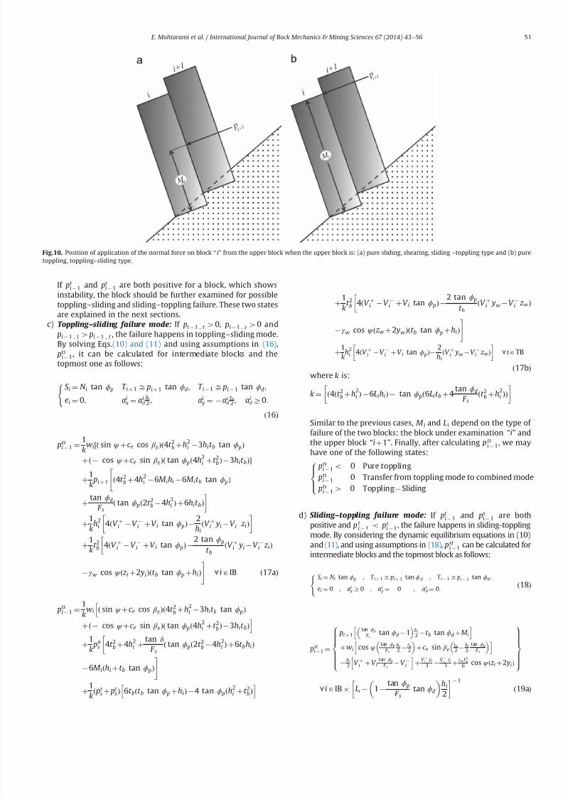
7232019 Slope Stability 201312020
httpslidepdfcomreaderfullslope-stability-201312020 914
If pt i 1 and ps
i 1 are both positive for a block which showsinstability the block should be further examined for possibletopplingndashsliding and slidingndashtoppling failure These two statesare explained in the next sections
c) Toppling ndashsliding failure mode If pi 1 t 40 pi 1 s40 and pi 1 t 4 pi 1 t the failure happens in topplingndashsliding modeBy solving Eqs(10) and (11) and using assumptions in (16) pts
i 1 it can be calculated for intermediate blocks and thetopmost one as follows
S i frac14 N i tan ϕ p T i thorn 1 ffi pi thorn 1 tan ϕd T i 1 ffi pi 1 tan ϕd
ei frac14 0 ai x frac14 ai
θ hi
2 ai y frac14 ai
θ t b2 ai
θ Z0
(
eth16THORN
ptsi 1 frac14
1k
wifrac12eth sin ψ thorn c e cos β eTHORNeth4t 2b thornh2i 3hit b tan ϕ pTHORN
thorn eth cos ψ thornc e sin β eTHORNeth tan ϕ peth4h2i thornt 2bTHORN 3hit bTHORN
thorn1k pi thorn 1
eth4t 2b thorn4h
2i 6M ihi 6M it b tan ϕ pTHORN
thorn tan ϕd
F seth tan ϕ peth2t 2b 4h
2i THORN thorn6hit bTHORN
thorn1k
h2i 4ethV thorni V i thornV i tan ϕ pTHORN
2hi
ethV thorni yi V i z iTHORN
thorn1k
t 2b 4ethV thorni V i thornV i tan ϕ pTHORN
2 tan ϕ p
t bethV thorni yi V i z iTHORN
γ w cos ψ eth z i thorn2 yiTHORNetht b tan ϕ p thorn hiTHORN
8 iAIB eth17aTHORN
ptsi 1 frac14
1k
wi eth sin ψ thornc e cos β eTHORNeth4t 2b thorn h2i 3hit b tan ϕ pTHORN
hthorn eth cos ψ thornc e sin β eTHORNeth tan ϕ peth4h
2i thornt 2bTHORN 3hit bTHORN
ithorn
1k pn
s 4t 2b thorn4h2i thorn
tan δ
F seth tan ϕ peth2t 2b 4h
2i THORN thorn6t bhiTHORN
6M iethhi thorn t b tan ϕ pTHORN
thorn1
k
eth pss thorn pc
s THORN 6t betht b tan ϕ p thornhiTHORN 4 tan ϕ pethh2i thornt 2bTHORNh i
thorn1k
t 2b 4ethV thorni V i thornV i tan ϕ pTHORN 2 tan ϕ p
t bethV thorn
i yw V i z wTHORN
γ w cos ψ eth z w thorn2 ywTHORNetht b tan ϕ p thorn hiTHORN
thorn1k
h2i 4ethV thorni V i thorn V i tan ϕ pTHORN
2hi
ethV thorni yw V i z wTHORN
8 iATB
eth17bTHORNwhere k is
k frac14 eth4etht 2b thorn h2i THORN 6LihiTHORN tan ϕ peth6Lit b thorn4
tan ϕd
F setht 2b thornh
2i THORNTHORN
Similar to the previous cases M i and Li depend on the type of failure of the two blocks the block under examination ldquoirdquo andthe upper block ldquoithorn1rdquo Finally after calculating p ts
i 1 we mayhave one of the following states
ptsi 1o 0 Pure toppling
ptsi 1 0 Transfer from toppling mode to combined mode
ptsi 14 0 TopplingSliding
8gtltgt
d) Sliding ndashtoppling failure mode If pt i 1 and ps
i 1 are bothpositive and p t
i 1 o psi 1 the failure happens in sliding-toppling
mode By considering the dynamic equilibrium equations in (10)and (11) and using assumptions in (18) pst
i 1 can be calculated forintermediate blocks and the topmost block as follows
S i frac14 N i tan ϕ p T i thorn 1 ffi pi thorn 1 tan ϕd T i 1 ffi pi 1 tan ϕd
ei frac14 0 ai xZ0 ai
y frac14 0 aiθ frac14 0
8lt eth18THORN
pst i 1 frac14
pi thorn 1tan ϕ p
F stan ϕd 1
hi
2 t b tan ϕd thornM i
h ithorn wi cos ψ
tan ϕ p
F shi
2 t b2
thorn c e sin β e
t b2 hi
2tan ϕ p
F s
h i hi
2 V thorni thorn V itan ϕ p
F s V i
h ithorn
V thorni yi
3 V i z i
3 thornγ wt 2
b
6 cos ψ eth z i thorn2 yiTHORN
8gtgtgtgtgtltgtgtgtgtgt
9gtgtgtgtgt=gtgtgtgtgt
8 iAIB Li 1tan ϕ p
F stan ϕd
hi
2 1
eth19aTHORN
i M
p i +
1
a i M
p i + 1
i i
i + 1 i + 1
Fig10 Position of application of the normal force on block ldquo irdquo from the upper block when the upper block is (a) pure sliding shearing slidingndashtoppling type and (b) puretoppling topplingndashsliding type
E Mohtarami et al International Journal of Rock Mechanics amp Mining Sciences 67 (2014) 43ndash56 51
7232019 Slope Stability 201312020
httpslidepdfcomreaderfullslope-stability-201312020 1014
pst i 1 frac14
pns
tan ϕ p
F stan δ 1
hi
2 t b tan δ thorn M i
h ithornwi cos ψ
tan ϕ p
F s
hi
2 t b2
thornc e sin β e
t b2 hi
2tan ϕ p
F s
h i hi
2 eth pss thorn pc
s THORN tan ϕ p V thorni V itan ϕ p
F sthorn V i
h i
eth pss thorn pc s THORNt b thornV thorn
i
yi
3 V
i
z i3 thorn
γ w t 2
b6 cos ψ eth z i thorn2 yiTHORN
8gtgtgtgtgtgtgtgtlt
gtgtgtgtgtgtgtgt
9gtgtgtgtgtgtgtgt=
gtgtgtgtgtgtgtgt Li 1
tan ϕ p
F stan ϕd
hi
2
1
8 iATB eth19bTHORN
In this case M i and Li are determined as in the previous casesStability determination or the type of possible instability in thecalculated block is done as follows
pst i 1 0 Only sliding
pst i 1 0 Transfer from sliding mode to the slidingtoppling
pst i 14 0 SlidingToppling
8gtltgt
e) Stable mode When psi 1 pt
i 1 o 0 the block is stable In this
case there is no need to calculate ptsi 1 and p
st i 1 Also pi 1 is
assumed to be zero in the subsequent calculation for other blocksIf this condition happens for the topmost block the soil mass hasno effect on the blocks system In this case the secondary topplingis not a probable mode of failure However any other topplingmode may still happen
42 Flexural toppling mode
If block ldquoirdquo is connected to the rock at the base of the slopeforming a cantilever position (Fig 8b) it shows tensile strengthdue to the bending state of loading Three modes ie 1047298exuraltoppling shearing and stable state can be expected
a) Flexural toppling mode In this mode column ldquoirdquo may fail dueto bending moment acting on the column Equilibrium equa-tions used in the previous section (Eqs (10) and (11))
can be used to analyze this state of loading The following
Is it first stagen = 0
Start
input parameters
NoYes
R e d u e F
s
u s i n g a r t i f i c i a l
b e e c o l o n y
Calculation of columnrsquos
data amp optimization of k a
F s = 1
Calculate of p i (i=0-n )
Display F s as an output
End
I n c r e a s e F
s
u s i n g a r t i f i c i a l
b e e c o l o n y
n = n+1n = n+1
Refer to algorithm shown in figure 12
Fig 11 A schematic algorithm of the computer codes process
Table 2
Input parameters which are used in the developed software
Input parameters Unit Input parameters Unit
Height of slope m Inclination of soil surface degreeAverage thickness of the layers in blocky mode m Friction angle between soil and rock mass degreeAverage thickness of the layers in 1047298exural mode m Internal soil friction angle degree
Distance between the soil mass to rock slopersquos crest m Cohesive in soil mass KNm
3
Slope angle with the horizontal degree Surface cohesive between the soil mass and rock KNm 3
Inclination of top surface of slope degree Friction angle of intact rock degreeInclination of the layers degree Tensile strength of rock mass KNm 3
Inclination of the failure plane degree Cohesive of intact rock sample KNm 3
Inclination of block base plane degree Pseudo-static seismic force coef 1047297cient ndash
Friction angle between block and underneath rock degree Deviation angle of the seismic force from x axis degreeFriction angle along the block interface degree
E Mohtarami et al International Journal of Rock Mechanics amp Mining Sciences 67 (2014) 43ndash56 52
7232019 Slope Stability 201312020
httpslidepdfcomreaderfullslope-stability-201312020 1114
assumptions are applicable
T i thorn 1 frac14 pi thorn 1 tan ϕd
T i 1 frac14 pi 1 tan ϕd
ei frac14 t f =2
ai x frac14 ai y frac14 0
8gtgtgtgtltgtgtgtgt
eth20THORN
Bending moment (M ) and axial force (N ) on the column at thebase point of the column are obtained as follows
N i frac14 wi cos ψ thornT i thorn 1 T i 1 V i c ewi sin β e eth21THORN
M frac14 wieth sin ψ thorn c e cos β eTHORNhi
2thorn pi thorn 1M i thorn
V thorni yi
3
t f
2ethT i thorn 1 thorn T i 1THORN
pi 1Li V
i z i3
V iLout eth22THORN
where Lout is the eccentric water pressure at base The total stressin the column should be calculated from both ldquoM rdquo and ldquoN rdquo as
shown in Eq (23) If the total tensile stress in rock column exceeds
the tensile rock strength st the rock breaks and the column isoverturned In equilibrium conditions the tensile stress mentionedin Eq (23) is equal to the tensile strength of rock It may berewritten as Eq (24) and safety factor of rock column against thetensile stress and hence against toppling is obtained from Eq (25)
s y frac14 t f =2t frac14
Mt f
2I i
N it f
eth23THORN
M frac142I it f
st thornN it f
eth24THORN
F s frac14 st =st f =2
y eth25THORN
By substituting ldquoM rdquo and ldquoN rdquo from Eqs (21) and (22) in Eq (24) p f t
i 1 is obtained as shown in Eq (26a) for the intermediatecolumns (IC) and in Eq (26b) for the topmost column (TC columnadjacent to soil mass) where I i is the second moment of columnldquoirdquo Similar to the previous cases Li and M i depend on failure type
of column or block ldquoirdquo
and ldquoithorn 1rdquo respectively
Block is
connected at its
bottom
Start
Initial calculations
NoYes
No
Yes No
Yes
No
Yes
Yes
No
Input parameters
Calculate of amp Calculate of amp
Calculate of Calculate of
Display output ie
and failure mode
End
Fig 12 An algorithm for calculating the ldquo pi1rdquofor column ldquoirdquo
Fig 13 (a) Overview of the slope and the Haraz road and (b) the soil part on top of the slope and partially equilibrium
E Mohtarami et al International Journal of Rock Mechanics amp Mining Sciences 67 (2014) 43ndash56 53
7232019 Slope Stability 201312020
httpslidepdfcomreaderfullslope-stability-201312020 1214
p f t i 1 frac14
pi thorn 1ethM i tan ϕdt f 2
2 tan ϕdI it 2 f
THORN
thornwihi
2 eth sin ψ thornc e cos β eTHORN thorn V iLout thornV thorni yi
3 thornV i z i
3
h i2I i
t f st
F sthorn
wi eth cos ψ c e sin β eTHORN V it f
8gtgtgtgtgtltgtgtgtgtgt
9gtgtgtgtgt=gtgtgtgtgt
tan ϕd
t f
2thornLi
2 tan ϕdI i
t 2 f
1
8 iAIC eth26aTHORN
p f t i 1 frac14
pns ethM i tan δ
t f 2THORN thornwi
hi
2 eth sin ψ thornc e cos β eTHORN
thorn V iLout thornV thorni yi
3 thornV i z i
3
h ieth ps
s thorn pc s THORN
t f 2
2I it f
st
F sthorn
wieth cos ψ c e sin β e THORN thorn pss thorn pc
s V it f
8gtgtgtgtltgtgtgtgt
9gtgtgtgt=gtgtgtgt
eth tan ϕd
t f
2thorn LiTHORN
1 8 iATC eth26bTHORN
b) Shear failure mode In this mode column ldquoirdquo may fail undershear force perpendicular to column axis The force shouldobviously overcome rock shear resistance mobilized by cohe-sive (C ) and friction (φr ) in intact rock By consideringassumptions in Eq (27) and limit equilibrium equations value
of pshi 1 for intermediate and topmost column it is obtained
from Eqs (28a) and (28b) respectively
T i thorn 1 ffi pi thorn 1 tan ϕd ei frac14 t f =2 ai x frac14 ai
y frac14 0
T i 1 ffi pi 1 tan ϕd S i frac14 N i tan ϕr thorn Ct f
(
eth27THORN
pshi 1 frac14 pi thorn 1 thorn wi eth cos ψ c e sin β eTHORN
tan ϕr
F s sin ψ c e cos β e
thorn V thorni thorn V itan ϕr
F s V i Ct f
) 8 iA IC 1
tan ϕr
F stan ϕd
1
eth28aTHORN
pshi 1 frac14 pn
s eth1 tan δ tan ϕr
F sTHORN wi eth cos ψ c e sin β eTHORN
tan ϕr
F s
sin ψ c e cos β e
8 iATC
eth pss thorn pc
s THORNtan ϕr
F sthorn V thorni thornV i
tan ϕr
F sV i Ct f
)
1 tan ϕr
F stan ϕd
1
eth28bTHORN
c) Stable mode When p f t i 1 psh
i 1r0 the column is stable and pi 1 is assumed to be zero in the subsequent calculation forother columns or blocks
5 Computer code developed for stability analysis
In the previous section a complete solution for circularndashtop-pling failure was presented To assess the overall stability of aslope with the combination of soil mass and rock columns thealgorithm shown in Fig 11 is proposed A computer code wasdeveloped using a user friend environment This algorithm wasused for slop stability evaluation and the calculation of safetyfactor Table 2 shows the input parameters The output for theintermediate stage of calculations is the forces between thecolumns ie pi 1 and pi thorn 1 for each column The 1047297nal output isthe force required to support toe column p0 and the safety factorof slope In this algorithm the coef 1047297cient of lateral earth pressurein the active mode ka is calculated using Eqs (1) to (4) for varioussoil conditions ldquoArti1047297cial bee colony optimizationrdquo algorithm wasused to optimize ka value Having found ka we calculated pi thorn 1 forthe topmost column using Eq (5) The values of pi 1 and pi thorn 1 iethe forces applied at both sides of each column are then calculatedaccording to the algorithm shown in Fig 12 and the formulationsdescribed in the previous section
53
25
45
6 7 0 m
3 1 9
2 m
77
Soil mass
Fig 14 A schematicof the slope located in Haraz
Table 3
Conducted tests in soil and rock parts
Conducted tests in rock parts Conducted tests in soil part
Test name Description Test name Description
Direct shear tests ϕfrac1428661 c jfrac14008 MPa Direct shear tests (using normal stress 5 Kgcm3) c frac14819 KNm 2 ϕfrac1427581Non-encapsulated strain s
avec frac14 14951 MPa Non-encapsulated strain sc frac142843 Kgcm 3
Dry and saturation density (Kgcm 3) γ dry frac14 262 γ sat frac14 2677 Determinat ion of speci1047297c gravity GS frac14259
Chemical testing of groundwater Water is not acidic or alkaline Chemical testing of groundwater Water is not acidic or alkalinePetrographic characteristics (dominant mineral) Quartz potassic feldspar biotite Dry and saturation density (Kgcm 3) γ dry frac14 1577 γ sat frac14 1968
Porosity and saturation percent n frac14 516 s frac14 2578 Porosity and saturation percent n frac14 391 s frac14 70Determination E and υ (21 samples) υ frac14 0239 E frac14 1607 ethGPaTHORN Determination E and υ υ frac14 036 E frac14 1250 ethKg =cm2THORN
The ultrasonic wave velocity V com frac14 3220 V sh frac14 1853 ethm=sTHORN The ultrasonic wave velocity V com frac14 1155 V sh frac14 540 ethm=sTHORN
E Mohtarami et al International Journal of Rock Mechanics amp Mining Sciences 67 (2014) 43ndash56 54
7232019 Slope Stability 201312020
httpslidepdfcomreaderfullslope-stability-201312020 1314
By 1047297nding p0 (ie p i 1 for toe column) the stability of a slopesubject to circular-toppling failure can be judged as follows
p04 0 Unstable
p0 frac14 0 Limit equilibrium condition
p0o 0 Stable
8gtlt
gt It should be noted that safety factor ethF sTHORN is set equal to 1 for
1047297nding p0 at the initial stage If p0 frac14 0 at the initial calculations theslope is at equilibrium state and calculation is no longer necessaryIf p040 then the slope is unstable and the value of F s is reducedgradually until p0 frac14 0 The 1047297nal calculated F s is the actual safetyfactor of the slope Similarly if p0o0 then the slope is stable Theactual safety factor is found by increasing the amount of F s incalculation loop till p0 frac14 0 The 1047297nal calculated F s is the actualsafety factor of the slope The increase or reduction of F s anddetermination of the optimum value are done using the arti1047297cialbee colony algorithm (Fig 11) In the previous studies the blockshave been alternately considered in blocky or 1047298exural topplingmode The proposed solution in this paper freely allows for anycombination
6 Case study
A real case including a slope subject to failure was studiedusing the proposed method This slope is located in Vana villagealong Haraz road in northern Iran 70 km from Amol city Theslope consists of rhyolite tuff overlooking Haraz road with thepotential of toppling Fig 13 shows the general view of the slopeand Fig 14 depicts the slope schematically As can be seen in these1047297gures a large amount of sediments and volcanic debris isdumped on the top of slope behind the rock columns This massgenerates the soil active pressure Ongoing erosion of the sedi-ments and volcanic rock not only increases the active pressure butalso causes the rock falls which have already caused some
accidents and injuries Due to the concern of possible failure of block rocks a research project was organized by research instituteof the Ministry of Roads and Urban Development for the evalua-tion of the general stability of the slope The existing residentialand commercial buildings next to this slope helped authoritiesaccept the minimum F S to be equal to 155
A number of exploration drillings were performed within theslope to obtain the geo-mechanical properties Moreover observa-tions were made through the existing tunnel of an old coal mine inthe area Table 3 shows the main obtained data used for this study
The stability of the slope in Vana village was analyzed using theproposed method and the developed code The code shows severalitems as outputs (a) Geometry and geo-mechanical parameterswhich are partially inputted by the user and partially calculated
by the code (b) forces between the columns ( pi1 and p ithorn1) and
possible failure mode of each block and (c) safety factor andstability state of the slope Furthermore we can obtain the appliedforce on topmost block by the soil by running the computer code
The analysis revealed that safety factor for this slope was equalto 164 for combined circularndashtoppling failure which was higherthan the acceptable 1047297gure by authorities The slope was found atstable state however it should be noted that due to futureerosions soil value and active soil pressure may increase during
the years Thus update evaluation may be necessary from time totime Moreover despite the general stability of this slope localrock falls can still happen Fig 15 shows potential rock falls due toerosion resulted by the running water
7 Conclusions
Different types of the toppling failure are still a major instabil-ity for slopes in nature and slopes all over the world Combinedcircularndashtoppling failure is a kind of instability not studied beforein details In this paper a complete solution was presented for thistype of failure A new formulation was developed to investigatethe stability of slope components (the soil and rock part)
The developed solution in this paper has taken all the effectiveparameters (external forces water pressure and earthquake) intoaccount Every column can be in any mode of failure including astable mode The presented solution unstable forms were widelyanalyzed from the point of limit equilibrium method in discontin-uous rock and allowed for any combination of failure in thecolumns ie failure mode of each column could be different withthe mode of neighboring columns Another advantage of theproposed solution is that the topmost column can have anyinclination and the applied force by soil mass can be calculatedby plasticity theory which has good accuracy
A computer code was developed to ease the use of the proposedsolution The code was simple and fast it gave the 1047297nal state of stability as well as safety factor of the slope By using this code the
effect of different parameters (like block inclination friction etc) onstability can be simply and quickly studied Such a study can helpthe users decide on the necessary measures for making the slopemore stable
References
[1] Goodman RE Bray JW Toppling of rock slopes In Boulder CO Proceedings of the specialty conference on rock engineering for foundations and slopesNew York American Society of Civil Engineers 15ndash18 August 1976 p 201ndash23
[2] Amini M Majdi A Veshadi MA Stability analysis of rock slopes against blockndash
1047298exure toppling failure Int J Rock Mech Rock Eng 201245(4)519ndash32[3] Collin A Recherches expeacuterimentaux sur les glissements spontaneacutes des terrains
argileux Paris Carilian-Goeurley et Dalmont [4] Taylor DW Stability of Earth slopes J Boston Soc Civ Eng 19371337ndash86
[5] Willie DC Mah CW Rock slope engineering (civil and mining) 4th EditionUK Spoon Press London Taylor and Francis Group 2004[6] Bishop AW The use of the slip circle in the stability analysis of slopes
Geacuteotechnique 195557ndash17[7] Nonveiller E The stability analysis of slopes with a slide surface of general
shape Proc 6th Int Conf Soil Mech Found Eng Montreal 1965279ndash93[8] Morgenstern NR Price VE The analysis of the stability of generalised slip
surfaces Geacuteotechnique 19651579ndash93[9] Chen Z Morgenstern NR Extensions to the generalized method of slices for
stability analysis Can Geotech J 198320(1)104ndash19[10] Muller L New considerations of the Vaiont slide Felsmech Engenieurgeologie
19686(1)1ndash91[11] Ashby J Sliding and toppling modes of failure in models and jointed rock
slopes [MSc thesis] London United Kingdom London University ImperialCollege 1971
[12] Hofmann H Kinematische modellstudien zum boschungs-problem in regal-massig geklufteten medien [PhD thesis] Karlsruhe Germany University of Karlsruhe 1972
[13] De Freitas MH Watters RJ Some 1047297eld examples of toppling failure Geacuteotech-
nique 197323495ndash514
Fig 15 Erosion and destructionwithin rock section of the slope
E Mohtarami et al International Journal of Rock Mechanics amp Mining Sciences 67 (2014) 43ndash56 55
7232019 Slope Stability 201312020
httpslidepdfcomreaderfullslope-stability-201312020 1414
[14] Whyte RJA Study of progressive hanging wall caving at chambishi coppermine in Zambia using the base friction model concept [MSc thesis] LondonUnited Kingdom London University Imperial College 1973
[15] Soto CA Comparative study of slope modelling techniques for fracturedground [MSc thesis] London United Kingdom London University ImperialCollege 1974
[16] Zanbak C Design charts for rock slopes susceptible to toppling J Geotech EngASCE 19831091039ndash62
[17] Goodman R Shi G Block theory and its application to rock engineeringEnglewood Cliffs New Jersey Prentice-Hall 1985 338
[18] Aydan Ouml Shimizu Y Ichikawa Y The effective failure modes and stability of slopes
in rock mass with two discontinuity sets Rock Mech Rock Eng 198922(3)163ndash88[19] Davies JN Smith PLP Flexural toppling of siltstones during a temporary
excavation for a bridge foundation in North Devon In Hadson JA editorComprehensive rock engineering Oxford Pergamon Press 1993 p 759ndash75
[20] Zaruba Q Mencl V Engineering geology Amsterdam Elsevier 1976[21] Aydan Ouml Kawamoto T Stability of slopes and underground openings against
1047298exural toppling and their stabilization Rock Mech Rock Eng 199225(3)143ndash65[22] Adhikary DP Dyskin AV Jewell RJ Modeling of 1047298exural toppling failures of
rock slopes In Proceedings of the eighth international congress rockmechanics Tokyo 1995 p 25ndash9
[23] Adhikary DP Dyskin AV Jewell RJ Stewart DP A study of the mechanism of 1047298exural toppling failure of rock slopes Rock Mech Rock Eng 199730(2)75ndash93
[24] Adhikary DP Dyskin AV Modeling of progressive and instantaneous failure of foliated rock slopes Rock Mech Rock Eng 200740(4)349ndash62
[25] Aydan Ouml Amini M An experimental study on rock slopes against 1047298exuraltoppling failure under dynamic loading and some theoretical considerationsfor its stability assessment J Sch Mar Sci Technol 20097(2)25 ndash40
[26] Braja MD Principles of geotechnical engineering 7th edition Stamford USACengage learning 2010
[27] Lambe TW Whitman RV Soil mechanics Massachusetts institute of technol-ogy Cambridge Massachusetts John Wiley and Sons 1969
[28] Caquot A Kerisel J Table for the calculation of passive pressure activepressure and bearing capacity of foundations (trans by MA Bec London)Paris Gauthier-Villars 1948
[29] Janbu N 4thEarth pressure and bearing capacity calculations by generalizedprocedure of slices Vol 2 London ICSMFE 1957 207ndash12
[30] Shields DH Tolunay AZ Passive pressure coef 1047297cients by method of slices JSMFD AS CE 197399(SM 12)S1043ndash53
[31] Sokolovski VV Statics of granular media Oxford Pergamon Press 1965 [32] Behnia K Tabatabai AM Soil mechanics 2nd Ed Tehran Tehran University
Press 1987[33] Chen WF Rosenfarb JL Limit analysis solutions of Earth pressure problems
Jpn S oc Soil Mech Found Eng 197313(4)45ndash60[34] PLAXIS V8 Finite element code for soil and rock analyses PLAXIS-3D
Reference manual Edited by Brinkgreve et al DUT The Netherlands langwwwplaxisnl2004rang
E Mohtarami et al International Journal of Rock Mechanics amp Mining Sciences 67 (2014) 43ndash56 56
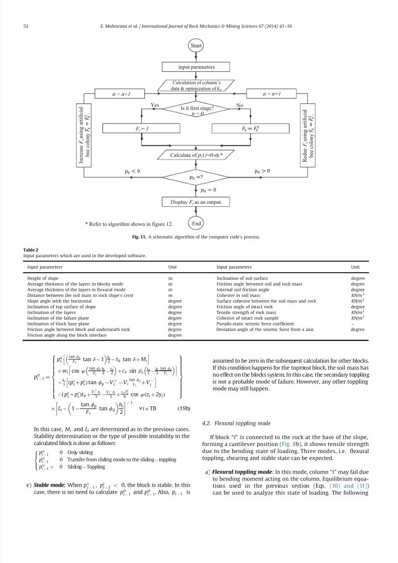
7232019 Slope Stability 201312020
httpslidepdfcomreaderfullslope-stability-201312020 1014
pst i 1 frac14
pns
tan ϕ p
F stan δ 1
hi
2 t b tan δ thorn M i
h ithornwi cos ψ
tan ϕ p
F s
hi
2 t b2
thornc e sin β e
t b2 hi
2tan ϕ p
F s
h i hi
2 eth pss thorn pc
s THORN tan ϕ p V thorni V itan ϕ p
F sthorn V i
h i
eth pss thorn pc s THORNt b thornV thorn
i
yi
3 V
i
z i3 thorn
γ w t 2
b6 cos ψ eth z i thorn2 yiTHORN
8gtgtgtgtgtgtgtgtlt
gtgtgtgtgtgtgtgt
9gtgtgtgtgtgtgtgt=
gtgtgtgtgtgtgtgt Li 1
tan ϕ p
F stan ϕd
hi
2
1
8 iATB eth19bTHORN
In this case M i and Li are determined as in the previous casesStability determination or the type of possible instability in thecalculated block is done as follows
pst i 1 0 Only sliding
pst i 1 0 Transfer from sliding mode to the slidingtoppling
pst i 14 0 SlidingToppling
8gtltgt
e) Stable mode When psi 1 pt
i 1 o 0 the block is stable In this
case there is no need to calculate ptsi 1 and p
st i 1 Also pi 1 is
assumed to be zero in the subsequent calculation for other blocksIf this condition happens for the topmost block the soil mass hasno effect on the blocks system In this case the secondary topplingis not a probable mode of failure However any other topplingmode may still happen
42 Flexural toppling mode
If block ldquoirdquo is connected to the rock at the base of the slopeforming a cantilever position (Fig 8b) it shows tensile strengthdue to the bending state of loading Three modes ie 1047298exuraltoppling shearing and stable state can be expected
a) Flexural toppling mode In this mode column ldquoirdquo may fail dueto bending moment acting on the column Equilibrium equa-tions used in the previous section (Eqs (10) and (11))
can be used to analyze this state of loading The following
Is it first stagen = 0
Start
input parameters
NoYes
R e d u e F
s
u s i n g a r t i f i c i a l
b e e c o l o n y
Calculation of columnrsquos
data amp optimization of k a
F s = 1
Calculate of p i (i=0-n )
Display F s as an output
End
I n c r e a s e F
s
u s i n g a r t i f i c i a l
b e e c o l o n y
n = n+1n = n+1
Refer to algorithm shown in figure 12
Fig 11 A schematic algorithm of the computer codes process
Table 2
Input parameters which are used in the developed software
Input parameters Unit Input parameters Unit
Height of slope m Inclination of soil surface degreeAverage thickness of the layers in blocky mode m Friction angle between soil and rock mass degreeAverage thickness of the layers in 1047298exural mode m Internal soil friction angle degree
Distance between the soil mass to rock slopersquos crest m Cohesive in soil mass KNm
3
Slope angle with the horizontal degree Surface cohesive between the soil mass and rock KNm 3
Inclination of top surface of slope degree Friction angle of intact rock degreeInclination of the layers degree Tensile strength of rock mass KNm 3
Inclination of the failure plane degree Cohesive of intact rock sample KNm 3
Inclination of block base plane degree Pseudo-static seismic force coef 1047297cient ndash
Friction angle between block and underneath rock degree Deviation angle of the seismic force from x axis degreeFriction angle along the block interface degree
E Mohtarami et al International Journal of Rock Mechanics amp Mining Sciences 67 (2014) 43ndash56 52
7232019 Slope Stability 201312020
httpslidepdfcomreaderfullslope-stability-201312020 1114
assumptions are applicable
T i thorn 1 frac14 pi thorn 1 tan ϕd
T i 1 frac14 pi 1 tan ϕd
ei frac14 t f =2
ai x frac14 ai y frac14 0
8gtgtgtgtltgtgtgtgt
eth20THORN
Bending moment (M ) and axial force (N ) on the column at thebase point of the column are obtained as follows
N i frac14 wi cos ψ thornT i thorn 1 T i 1 V i c ewi sin β e eth21THORN
M frac14 wieth sin ψ thorn c e cos β eTHORNhi
2thorn pi thorn 1M i thorn
V thorni yi
3
t f
2ethT i thorn 1 thorn T i 1THORN
pi 1Li V
i z i3
V iLout eth22THORN
where Lout is the eccentric water pressure at base The total stressin the column should be calculated from both ldquoM rdquo and ldquoN rdquo as
shown in Eq (23) If the total tensile stress in rock column exceeds
the tensile rock strength st the rock breaks and the column isoverturned In equilibrium conditions the tensile stress mentionedin Eq (23) is equal to the tensile strength of rock It may berewritten as Eq (24) and safety factor of rock column against thetensile stress and hence against toppling is obtained from Eq (25)
s y frac14 t f =2t frac14
Mt f
2I i
N it f
eth23THORN
M frac142I it f
st thornN it f
eth24THORN
F s frac14 st =st f =2
y eth25THORN
By substituting ldquoM rdquo and ldquoN rdquo from Eqs (21) and (22) in Eq (24) p f t
i 1 is obtained as shown in Eq (26a) for the intermediatecolumns (IC) and in Eq (26b) for the topmost column (TC columnadjacent to soil mass) where I i is the second moment of columnldquoirdquo Similar to the previous cases Li and M i depend on failure type
of column or block ldquoirdquo
and ldquoithorn 1rdquo respectively
Block is
connected at its
bottom
Start
Initial calculations
NoYes
No
Yes No
Yes
No
Yes
Yes
No
Input parameters
Calculate of amp Calculate of amp
Calculate of Calculate of
Display output ie
and failure mode
End
Fig 12 An algorithm for calculating the ldquo pi1rdquofor column ldquoirdquo
Fig 13 (a) Overview of the slope and the Haraz road and (b) the soil part on top of the slope and partially equilibrium
E Mohtarami et al International Journal of Rock Mechanics amp Mining Sciences 67 (2014) 43ndash56 53
7232019 Slope Stability 201312020
httpslidepdfcomreaderfullslope-stability-201312020 1214
p f t i 1 frac14
pi thorn 1ethM i tan ϕdt f 2
2 tan ϕdI it 2 f
THORN
thornwihi
2 eth sin ψ thornc e cos β eTHORN thorn V iLout thornV thorni yi
3 thornV i z i
3
h i2I i
t f st
F sthorn
wi eth cos ψ c e sin β eTHORN V it f
8gtgtgtgtgtltgtgtgtgtgt
9gtgtgtgtgt=gtgtgtgtgt
tan ϕd
t f
2thornLi
2 tan ϕdI i
t 2 f
1
8 iAIC eth26aTHORN
p f t i 1 frac14
pns ethM i tan δ
t f 2THORN thornwi
hi
2 eth sin ψ thornc e cos β eTHORN
thorn V iLout thornV thorni yi
3 thornV i z i
3
h ieth ps
s thorn pc s THORN
t f 2
2I it f
st
F sthorn
wieth cos ψ c e sin β e THORN thorn pss thorn pc
s V it f
8gtgtgtgtltgtgtgtgt
9gtgtgtgt=gtgtgtgt
eth tan ϕd
t f
2thorn LiTHORN
1 8 iATC eth26bTHORN
b) Shear failure mode In this mode column ldquoirdquo may fail undershear force perpendicular to column axis The force shouldobviously overcome rock shear resistance mobilized by cohe-sive (C ) and friction (φr ) in intact rock By consideringassumptions in Eq (27) and limit equilibrium equations value
of pshi 1 for intermediate and topmost column it is obtained
from Eqs (28a) and (28b) respectively
T i thorn 1 ffi pi thorn 1 tan ϕd ei frac14 t f =2 ai x frac14 ai
y frac14 0
T i 1 ffi pi 1 tan ϕd S i frac14 N i tan ϕr thorn Ct f
(
eth27THORN
pshi 1 frac14 pi thorn 1 thorn wi eth cos ψ c e sin β eTHORN
tan ϕr
F s sin ψ c e cos β e
thorn V thorni thorn V itan ϕr
F s V i Ct f
) 8 iA IC 1
tan ϕr
F stan ϕd
1
eth28aTHORN
pshi 1 frac14 pn
s eth1 tan δ tan ϕr
F sTHORN wi eth cos ψ c e sin β eTHORN
tan ϕr
F s
sin ψ c e cos β e
8 iATC
eth pss thorn pc
s THORNtan ϕr
F sthorn V thorni thornV i
tan ϕr
F sV i Ct f
)
1 tan ϕr
F stan ϕd
1
eth28bTHORN
c) Stable mode When p f t i 1 psh
i 1r0 the column is stable and pi 1 is assumed to be zero in the subsequent calculation forother columns or blocks
5 Computer code developed for stability analysis
In the previous section a complete solution for circularndashtop-pling failure was presented To assess the overall stability of aslope with the combination of soil mass and rock columns thealgorithm shown in Fig 11 is proposed A computer code wasdeveloped using a user friend environment This algorithm wasused for slop stability evaluation and the calculation of safetyfactor Table 2 shows the input parameters The output for theintermediate stage of calculations is the forces between thecolumns ie pi 1 and pi thorn 1 for each column The 1047297nal output isthe force required to support toe column p0 and the safety factorof slope In this algorithm the coef 1047297cient of lateral earth pressurein the active mode ka is calculated using Eqs (1) to (4) for varioussoil conditions ldquoArti1047297cial bee colony optimizationrdquo algorithm wasused to optimize ka value Having found ka we calculated pi thorn 1 forthe topmost column using Eq (5) The values of pi 1 and pi thorn 1 iethe forces applied at both sides of each column are then calculatedaccording to the algorithm shown in Fig 12 and the formulationsdescribed in the previous section
53
25
45
6 7 0 m
3 1 9
2 m
77
Soil mass
Fig 14 A schematicof the slope located in Haraz
Table 3
Conducted tests in soil and rock parts
Conducted tests in rock parts Conducted tests in soil part
Test name Description Test name Description
Direct shear tests ϕfrac1428661 c jfrac14008 MPa Direct shear tests (using normal stress 5 Kgcm3) c frac14819 KNm 2 ϕfrac1427581Non-encapsulated strain s
avec frac14 14951 MPa Non-encapsulated strain sc frac142843 Kgcm 3
Dry and saturation density (Kgcm 3) γ dry frac14 262 γ sat frac14 2677 Determinat ion of speci1047297c gravity GS frac14259
Chemical testing of groundwater Water is not acidic or alkaline Chemical testing of groundwater Water is not acidic or alkalinePetrographic characteristics (dominant mineral) Quartz potassic feldspar biotite Dry and saturation density (Kgcm 3) γ dry frac14 1577 γ sat frac14 1968
Porosity and saturation percent n frac14 516 s frac14 2578 Porosity and saturation percent n frac14 391 s frac14 70Determination E and υ (21 samples) υ frac14 0239 E frac14 1607 ethGPaTHORN Determination E and υ υ frac14 036 E frac14 1250 ethKg =cm2THORN
The ultrasonic wave velocity V com frac14 3220 V sh frac14 1853 ethm=sTHORN The ultrasonic wave velocity V com frac14 1155 V sh frac14 540 ethm=sTHORN
E Mohtarami et al International Journal of Rock Mechanics amp Mining Sciences 67 (2014) 43ndash56 54
7232019 Slope Stability 201312020
httpslidepdfcomreaderfullslope-stability-201312020 1314
By 1047297nding p0 (ie p i 1 for toe column) the stability of a slopesubject to circular-toppling failure can be judged as follows
p04 0 Unstable
p0 frac14 0 Limit equilibrium condition
p0o 0 Stable
8gtlt
gt It should be noted that safety factor ethF sTHORN is set equal to 1 for
1047297nding p0 at the initial stage If p0 frac14 0 at the initial calculations theslope is at equilibrium state and calculation is no longer necessaryIf p040 then the slope is unstable and the value of F s is reducedgradually until p0 frac14 0 The 1047297nal calculated F s is the actual safetyfactor of the slope Similarly if p0o0 then the slope is stable Theactual safety factor is found by increasing the amount of F s incalculation loop till p0 frac14 0 The 1047297nal calculated F s is the actualsafety factor of the slope The increase or reduction of F s anddetermination of the optimum value are done using the arti1047297cialbee colony algorithm (Fig 11) In the previous studies the blockshave been alternately considered in blocky or 1047298exural topplingmode The proposed solution in this paper freely allows for anycombination
6 Case study
A real case including a slope subject to failure was studiedusing the proposed method This slope is located in Vana villagealong Haraz road in northern Iran 70 km from Amol city Theslope consists of rhyolite tuff overlooking Haraz road with thepotential of toppling Fig 13 shows the general view of the slopeand Fig 14 depicts the slope schematically As can be seen in these1047297gures a large amount of sediments and volcanic debris isdumped on the top of slope behind the rock columns This massgenerates the soil active pressure Ongoing erosion of the sedi-ments and volcanic rock not only increases the active pressure butalso causes the rock falls which have already caused some
accidents and injuries Due to the concern of possible failure of block rocks a research project was organized by research instituteof the Ministry of Roads and Urban Development for the evalua-tion of the general stability of the slope The existing residentialand commercial buildings next to this slope helped authoritiesaccept the minimum F S to be equal to 155
A number of exploration drillings were performed within theslope to obtain the geo-mechanical properties Moreover observa-tions were made through the existing tunnel of an old coal mine inthe area Table 3 shows the main obtained data used for this study
The stability of the slope in Vana village was analyzed using theproposed method and the developed code The code shows severalitems as outputs (a) Geometry and geo-mechanical parameterswhich are partially inputted by the user and partially calculated
by the code (b) forces between the columns ( pi1 and p ithorn1) and
possible failure mode of each block and (c) safety factor andstability state of the slope Furthermore we can obtain the appliedforce on topmost block by the soil by running the computer code
The analysis revealed that safety factor for this slope was equalto 164 for combined circularndashtoppling failure which was higherthan the acceptable 1047297gure by authorities The slope was found atstable state however it should be noted that due to futureerosions soil value and active soil pressure may increase during
the years Thus update evaluation may be necessary from time totime Moreover despite the general stability of this slope localrock falls can still happen Fig 15 shows potential rock falls due toerosion resulted by the running water
7 Conclusions
Different types of the toppling failure are still a major instabil-ity for slopes in nature and slopes all over the world Combinedcircularndashtoppling failure is a kind of instability not studied beforein details In this paper a complete solution was presented for thistype of failure A new formulation was developed to investigatethe stability of slope components (the soil and rock part)
The developed solution in this paper has taken all the effectiveparameters (external forces water pressure and earthquake) intoaccount Every column can be in any mode of failure including astable mode The presented solution unstable forms were widelyanalyzed from the point of limit equilibrium method in discontin-uous rock and allowed for any combination of failure in thecolumns ie failure mode of each column could be different withthe mode of neighboring columns Another advantage of theproposed solution is that the topmost column can have anyinclination and the applied force by soil mass can be calculatedby plasticity theory which has good accuracy
A computer code was developed to ease the use of the proposedsolution The code was simple and fast it gave the 1047297nal state of stability as well as safety factor of the slope By using this code the
effect of different parameters (like block inclination friction etc) onstability can be simply and quickly studied Such a study can helpthe users decide on the necessary measures for making the slopemore stable
References
[1] Goodman RE Bray JW Toppling of rock slopes In Boulder CO Proceedings of the specialty conference on rock engineering for foundations and slopesNew York American Society of Civil Engineers 15ndash18 August 1976 p 201ndash23
[2] Amini M Majdi A Veshadi MA Stability analysis of rock slopes against blockndash
1047298exure toppling failure Int J Rock Mech Rock Eng 201245(4)519ndash32[3] Collin A Recherches expeacuterimentaux sur les glissements spontaneacutes des terrains
argileux Paris Carilian-Goeurley et Dalmont [4] Taylor DW Stability of Earth slopes J Boston Soc Civ Eng 19371337ndash86
[5] Willie DC Mah CW Rock slope engineering (civil and mining) 4th EditionUK Spoon Press London Taylor and Francis Group 2004[6] Bishop AW The use of the slip circle in the stability analysis of slopes
Geacuteotechnique 195557ndash17[7] Nonveiller E The stability analysis of slopes with a slide surface of general
shape Proc 6th Int Conf Soil Mech Found Eng Montreal 1965279ndash93[8] Morgenstern NR Price VE The analysis of the stability of generalised slip
surfaces Geacuteotechnique 19651579ndash93[9] Chen Z Morgenstern NR Extensions to the generalized method of slices for
stability analysis Can Geotech J 198320(1)104ndash19[10] Muller L New considerations of the Vaiont slide Felsmech Engenieurgeologie
19686(1)1ndash91[11] Ashby J Sliding and toppling modes of failure in models and jointed rock
slopes [MSc thesis] London United Kingdom London University ImperialCollege 1971
[12] Hofmann H Kinematische modellstudien zum boschungs-problem in regal-massig geklufteten medien [PhD thesis] Karlsruhe Germany University of Karlsruhe 1972
[13] De Freitas MH Watters RJ Some 1047297eld examples of toppling failure Geacuteotech-
nique 197323495ndash514
Fig 15 Erosion and destructionwithin rock section of the slope
E Mohtarami et al International Journal of Rock Mechanics amp Mining Sciences 67 (2014) 43ndash56 55
7232019 Slope Stability 201312020
httpslidepdfcomreaderfullslope-stability-201312020 1414
[14] Whyte RJA Study of progressive hanging wall caving at chambishi coppermine in Zambia using the base friction model concept [MSc thesis] LondonUnited Kingdom London University Imperial College 1973
[15] Soto CA Comparative study of slope modelling techniques for fracturedground [MSc thesis] London United Kingdom London University ImperialCollege 1974
[16] Zanbak C Design charts for rock slopes susceptible to toppling J Geotech EngASCE 19831091039ndash62
[17] Goodman R Shi G Block theory and its application to rock engineeringEnglewood Cliffs New Jersey Prentice-Hall 1985 338
[18] Aydan Ouml Shimizu Y Ichikawa Y The effective failure modes and stability of slopes
in rock mass with two discontinuity sets Rock Mech Rock Eng 198922(3)163ndash88[19] Davies JN Smith PLP Flexural toppling of siltstones during a temporary
excavation for a bridge foundation in North Devon In Hadson JA editorComprehensive rock engineering Oxford Pergamon Press 1993 p 759ndash75
[20] Zaruba Q Mencl V Engineering geology Amsterdam Elsevier 1976[21] Aydan Ouml Kawamoto T Stability of slopes and underground openings against
1047298exural toppling and their stabilization Rock Mech Rock Eng 199225(3)143ndash65[22] Adhikary DP Dyskin AV Jewell RJ Modeling of 1047298exural toppling failures of
rock slopes In Proceedings of the eighth international congress rockmechanics Tokyo 1995 p 25ndash9
[23] Adhikary DP Dyskin AV Jewell RJ Stewart DP A study of the mechanism of 1047298exural toppling failure of rock slopes Rock Mech Rock Eng 199730(2)75ndash93
[24] Adhikary DP Dyskin AV Modeling of progressive and instantaneous failure of foliated rock slopes Rock Mech Rock Eng 200740(4)349ndash62
[25] Aydan Ouml Amini M An experimental study on rock slopes against 1047298exuraltoppling failure under dynamic loading and some theoretical considerationsfor its stability assessment J Sch Mar Sci Technol 20097(2)25 ndash40
[26] Braja MD Principles of geotechnical engineering 7th edition Stamford USACengage learning 2010
[27] Lambe TW Whitman RV Soil mechanics Massachusetts institute of technol-ogy Cambridge Massachusetts John Wiley and Sons 1969
[28] Caquot A Kerisel J Table for the calculation of passive pressure activepressure and bearing capacity of foundations (trans by MA Bec London)Paris Gauthier-Villars 1948
[29] Janbu N 4thEarth pressure and bearing capacity calculations by generalizedprocedure of slices Vol 2 London ICSMFE 1957 207ndash12
[30] Shields DH Tolunay AZ Passive pressure coef 1047297cients by method of slices JSMFD AS CE 197399(SM 12)S1043ndash53
[31] Sokolovski VV Statics of granular media Oxford Pergamon Press 1965 [32] Behnia K Tabatabai AM Soil mechanics 2nd Ed Tehran Tehran University
Press 1987[33] Chen WF Rosenfarb JL Limit analysis solutions of Earth pressure problems
Jpn S oc Soil Mech Found Eng 197313(4)45ndash60[34] PLAXIS V8 Finite element code for soil and rock analyses PLAXIS-3D
Reference manual Edited by Brinkgreve et al DUT The Netherlands langwwwplaxisnl2004rang
E Mohtarami et al International Journal of Rock Mechanics amp Mining Sciences 67 (2014) 43ndash56 56
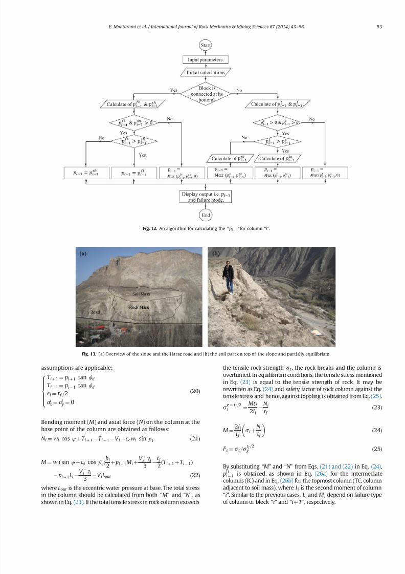
7232019 Slope Stability 201312020
httpslidepdfcomreaderfullslope-stability-201312020 1114
assumptions are applicable
T i thorn 1 frac14 pi thorn 1 tan ϕd
T i 1 frac14 pi 1 tan ϕd
ei frac14 t f =2
ai x frac14 ai y frac14 0
8gtgtgtgtltgtgtgtgt
eth20THORN
Bending moment (M ) and axial force (N ) on the column at thebase point of the column are obtained as follows
N i frac14 wi cos ψ thornT i thorn 1 T i 1 V i c ewi sin β e eth21THORN
M frac14 wieth sin ψ thorn c e cos β eTHORNhi
2thorn pi thorn 1M i thorn
V thorni yi
3
t f
2ethT i thorn 1 thorn T i 1THORN
pi 1Li V
i z i3
V iLout eth22THORN
where Lout is the eccentric water pressure at base The total stressin the column should be calculated from both ldquoM rdquo and ldquoN rdquo as
shown in Eq (23) If the total tensile stress in rock column exceeds
the tensile rock strength st the rock breaks and the column isoverturned In equilibrium conditions the tensile stress mentionedin Eq (23) is equal to the tensile strength of rock It may berewritten as Eq (24) and safety factor of rock column against thetensile stress and hence against toppling is obtained from Eq (25)
s y frac14 t f =2t frac14
Mt f
2I i
N it f
eth23THORN
M frac142I it f
st thornN it f
eth24THORN
F s frac14 st =st f =2
y eth25THORN
By substituting ldquoM rdquo and ldquoN rdquo from Eqs (21) and (22) in Eq (24) p f t
i 1 is obtained as shown in Eq (26a) for the intermediatecolumns (IC) and in Eq (26b) for the topmost column (TC columnadjacent to soil mass) where I i is the second moment of columnldquoirdquo Similar to the previous cases Li and M i depend on failure type
of column or block ldquoirdquo
and ldquoithorn 1rdquo respectively
Block is
connected at its
bottom
Start
Initial calculations
NoYes
No
Yes No
Yes
No
Yes
Yes
No
Input parameters
Calculate of amp Calculate of amp
Calculate of Calculate of
Display output ie
and failure mode
End
Fig 12 An algorithm for calculating the ldquo pi1rdquofor column ldquoirdquo
Fig 13 (a) Overview of the slope and the Haraz road and (b) the soil part on top of the slope and partially equilibrium
E Mohtarami et al International Journal of Rock Mechanics amp Mining Sciences 67 (2014) 43ndash56 53
7232019 Slope Stability 201312020
httpslidepdfcomreaderfullslope-stability-201312020 1214
p f t i 1 frac14
pi thorn 1ethM i tan ϕdt f 2
2 tan ϕdI it 2 f
THORN
thornwihi
2 eth sin ψ thornc e cos β eTHORN thorn V iLout thornV thorni yi
3 thornV i z i
3
h i2I i
t f st
F sthorn
wi eth cos ψ c e sin β eTHORN V it f
8gtgtgtgtgtltgtgtgtgtgt
9gtgtgtgtgt=gtgtgtgtgt
tan ϕd
t f
2thornLi
2 tan ϕdI i
t 2 f
1
8 iAIC eth26aTHORN
p f t i 1 frac14
pns ethM i tan δ
t f 2THORN thornwi
hi
2 eth sin ψ thornc e cos β eTHORN
thorn V iLout thornV thorni yi
3 thornV i z i
3
h ieth ps
s thorn pc s THORN
t f 2
2I it f
st
F sthorn
wieth cos ψ c e sin β e THORN thorn pss thorn pc
s V it f
8gtgtgtgtltgtgtgtgt
9gtgtgtgt=gtgtgtgt
eth tan ϕd
t f
2thorn LiTHORN
1 8 iATC eth26bTHORN
b) Shear failure mode In this mode column ldquoirdquo may fail undershear force perpendicular to column axis The force shouldobviously overcome rock shear resistance mobilized by cohe-sive (C ) and friction (φr ) in intact rock By consideringassumptions in Eq (27) and limit equilibrium equations value
of pshi 1 for intermediate and topmost column it is obtained
from Eqs (28a) and (28b) respectively
T i thorn 1 ffi pi thorn 1 tan ϕd ei frac14 t f =2 ai x frac14 ai
y frac14 0
T i 1 ffi pi 1 tan ϕd S i frac14 N i tan ϕr thorn Ct f
(
eth27THORN
pshi 1 frac14 pi thorn 1 thorn wi eth cos ψ c e sin β eTHORN
tan ϕr
F s sin ψ c e cos β e
thorn V thorni thorn V itan ϕr
F s V i Ct f
) 8 iA IC 1
tan ϕr
F stan ϕd
1
eth28aTHORN
pshi 1 frac14 pn
s eth1 tan δ tan ϕr
F sTHORN wi eth cos ψ c e sin β eTHORN
tan ϕr
F s
sin ψ c e cos β e
8 iATC
eth pss thorn pc
s THORNtan ϕr
F sthorn V thorni thornV i
tan ϕr
F sV i Ct f
)
1 tan ϕr
F stan ϕd
1
eth28bTHORN
c) Stable mode When p f t i 1 psh
i 1r0 the column is stable and pi 1 is assumed to be zero in the subsequent calculation forother columns or blocks
5 Computer code developed for stability analysis
In the previous section a complete solution for circularndashtop-pling failure was presented To assess the overall stability of aslope with the combination of soil mass and rock columns thealgorithm shown in Fig 11 is proposed A computer code wasdeveloped using a user friend environment This algorithm wasused for slop stability evaluation and the calculation of safetyfactor Table 2 shows the input parameters The output for theintermediate stage of calculations is the forces between thecolumns ie pi 1 and pi thorn 1 for each column The 1047297nal output isthe force required to support toe column p0 and the safety factorof slope In this algorithm the coef 1047297cient of lateral earth pressurein the active mode ka is calculated using Eqs (1) to (4) for varioussoil conditions ldquoArti1047297cial bee colony optimizationrdquo algorithm wasused to optimize ka value Having found ka we calculated pi thorn 1 forthe topmost column using Eq (5) The values of pi 1 and pi thorn 1 iethe forces applied at both sides of each column are then calculatedaccording to the algorithm shown in Fig 12 and the formulationsdescribed in the previous section
53
25
45
6 7 0 m
3 1 9
2 m
77
Soil mass
Fig 14 A schematicof the slope located in Haraz
Table 3
Conducted tests in soil and rock parts
Conducted tests in rock parts Conducted tests in soil part
Test name Description Test name Description
Direct shear tests ϕfrac1428661 c jfrac14008 MPa Direct shear tests (using normal stress 5 Kgcm3) c frac14819 KNm 2 ϕfrac1427581Non-encapsulated strain s
avec frac14 14951 MPa Non-encapsulated strain sc frac142843 Kgcm 3
Dry and saturation density (Kgcm 3) γ dry frac14 262 γ sat frac14 2677 Determinat ion of speci1047297c gravity GS frac14259
Chemical testing of groundwater Water is not acidic or alkaline Chemical testing of groundwater Water is not acidic or alkalinePetrographic characteristics (dominant mineral) Quartz potassic feldspar biotite Dry and saturation density (Kgcm 3) γ dry frac14 1577 γ sat frac14 1968
Porosity and saturation percent n frac14 516 s frac14 2578 Porosity and saturation percent n frac14 391 s frac14 70Determination E and υ (21 samples) υ frac14 0239 E frac14 1607 ethGPaTHORN Determination E and υ υ frac14 036 E frac14 1250 ethKg =cm2THORN
The ultrasonic wave velocity V com frac14 3220 V sh frac14 1853 ethm=sTHORN The ultrasonic wave velocity V com frac14 1155 V sh frac14 540 ethm=sTHORN
E Mohtarami et al International Journal of Rock Mechanics amp Mining Sciences 67 (2014) 43ndash56 54
7232019 Slope Stability 201312020
httpslidepdfcomreaderfullslope-stability-201312020 1314
By 1047297nding p0 (ie p i 1 for toe column) the stability of a slopesubject to circular-toppling failure can be judged as follows
p04 0 Unstable
p0 frac14 0 Limit equilibrium condition
p0o 0 Stable
8gtlt
gt It should be noted that safety factor ethF sTHORN is set equal to 1 for
1047297nding p0 at the initial stage If p0 frac14 0 at the initial calculations theslope is at equilibrium state and calculation is no longer necessaryIf p040 then the slope is unstable and the value of F s is reducedgradually until p0 frac14 0 The 1047297nal calculated F s is the actual safetyfactor of the slope Similarly if p0o0 then the slope is stable Theactual safety factor is found by increasing the amount of F s incalculation loop till p0 frac14 0 The 1047297nal calculated F s is the actualsafety factor of the slope The increase or reduction of F s anddetermination of the optimum value are done using the arti1047297cialbee colony algorithm (Fig 11) In the previous studies the blockshave been alternately considered in blocky or 1047298exural topplingmode The proposed solution in this paper freely allows for anycombination
6 Case study
A real case including a slope subject to failure was studiedusing the proposed method This slope is located in Vana villagealong Haraz road in northern Iran 70 km from Amol city Theslope consists of rhyolite tuff overlooking Haraz road with thepotential of toppling Fig 13 shows the general view of the slopeand Fig 14 depicts the slope schematically As can be seen in these1047297gures a large amount of sediments and volcanic debris isdumped on the top of slope behind the rock columns This massgenerates the soil active pressure Ongoing erosion of the sedi-ments and volcanic rock not only increases the active pressure butalso causes the rock falls which have already caused some
accidents and injuries Due to the concern of possible failure of block rocks a research project was organized by research instituteof the Ministry of Roads and Urban Development for the evalua-tion of the general stability of the slope The existing residentialand commercial buildings next to this slope helped authoritiesaccept the minimum F S to be equal to 155
A number of exploration drillings were performed within theslope to obtain the geo-mechanical properties Moreover observa-tions were made through the existing tunnel of an old coal mine inthe area Table 3 shows the main obtained data used for this study
The stability of the slope in Vana village was analyzed using theproposed method and the developed code The code shows severalitems as outputs (a) Geometry and geo-mechanical parameterswhich are partially inputted by the user and partially calculated
by the code (b) forces between the columns ( pi1 and p ithorn1) and
possible failure mode of each block and (c) safety factor andstability state of the slope Furthermore we can obtain the appliedforce on topmost block by the soil by running the computer code
The analysis revealed that safety factor for this slope was equalto 164 for combined circularndashtoppling failure which was higherthan the acceptable 1047297gure by authorities The slope was found atstable state however it should be noted that due to futureerosions soil value and active soil pressure may increase during
the years Thus update evaluation may be necessary from time totime Moreover despite the general stability of this slope localrock falls can still happen Fig 15 shows potential rock falls due toerosion resulted by the running water
7 Conclusions
Different types of the toppling failure are still a major instabil-ity for slopes in nature and slopes all over the world Combinedcircularndashtoppling failure is a kind of instability not studied beforein details In this paper a complete solution was presented for thistype of failure A new formulation was developed to investigatethe stability of slope components (the soil and rock part)
The developed solution in this paper has taken all the effectiveparameters (external forces water pressure and earthquake) intoaccount Every column can be in any mode of failure including astable mode The presented solution unstable forms were widelyanalyzed from the point of limit equilibrium method in discontin-uous rock and allowed for any combination of failure in thecolumns ie failure mode of each column could be different withthe mode of neighboring columns Another advantage of theproposed solution is that the topmost column can have anyinclination and the applied force by soil mass can be calculatedby plasticity theory which has good accuracy
A computer code was developed to ease the use of the proposedsolution The code was simple and fast it gave the 1047297nal state of stability as well as safety factor of the slope By using this code the
effect of different parameters (like block inclination friction etc) onstability can be simply and quickly studied Such a study can helpthe users decide on the necessary measures for making the slopemore stable
References
[1] Goodman RE Bray JW Toppling of rock slopes In Boulder CO Proceedings of the specialty conference on rock engineering for foundations and slopesNew York American Society of Civil Engineers 15ndash18 August 1976 p 201ndash23
[2] Amini M Majdi A Veshadi MA Stability analysis of rock slopes against blockndash
1047298exure toppling failure Int J Rock Mech Rock Eng 201245(4)519ndash32[3] Collin A Recherches expeacuterimentaux sur les glissements spontaneacutes des terrains
argileux Paris Carilian-Goeurley et Dalmont [4] Taylor DW Stability of Earth slopes J Boston Soc Civ Eng 19371337ndash86
[5] Willie DC Mah CW Rock slope engineering (civil and mining) 4th EditionUK Spoon Press London Taylor and Francis Group 2004[6] Bishop AW The use of the slip circle in the stability analysis of slopes
Geacuteotechnique 195557ndash17[7] Nonveiller E The stability analysis of slopes with a slide surface of general
shape Proc 6th Int Conf Soil Mech Found Eng Montreal 1965279ndash93[8] Morgenstern NR Price VE The analysis of the stability of generalised slip
surfaces Geacuteotechnique 19651579ndash93[9] Chen Z Morgenstern NR Extensions to the generalized method of slices for
stability analysis Can Geotech J 198320(1)104ndash19[10] Muller L New considerations of the Vaiont slide Felsmech Engenieurgeologie
19686(1)1ndash91[11] Ashby J Sliding and toppling modes of failure in models and jointed rock
slopes [MSc thesis] London United Kingdom London University ImperialCollege 1971
[12] Hofmann H Kinematische modellstudien zum boschungs-problem in regal-massig geklufteten medien [PhD thesis] Karlsruhe Germany University of Karlsruhe 1972
[13] De Freitas MH Watters RJ Some 1047297eld examples of toppling failure Geacuteotech-
nique 197323495ndash514
Fig 15 Erosion and destructionwithin rock section of the slope
E Mohtarami et al International Journal of Rock Mechanics amp Mining Sciences 67 (2014) 43ndash56 55
7232019 Slope Stability 201312020
httpslidepdfcomreaderfullslope-stability-201312020 1414
[14] Whyte RJA Study of progressive hanging wall caving at chambishi coppermine in Zambia using the base friction model concept [MSc thesis] LondonUnited Kingdom London University Imperial College 1973
[15] Soto CA Comparative study of slope modelling techniques for fracturedground [MSc thesis] London United Kingdom London University ImperialCollege 1974
[16] Zanbak C Design charts for rock slopes susceptible to toppling J Geotech EngASCE 19831091039ndash62
[17] Goodman R Shi G Block theory and its application to rock engineeringEnglewood Cliffs New Jersey Prentice-Hall 1985 338
[18] Aydan Ouml Shimizu Y Ichikawa Y The effective failure modes and stability of slopes
in rock mass with two discontinuity sets Rock Mech Rock Eng 198922(3)163ndash88[19] Davies JN Smith PLP Flexural toppling of siltstones during a temporary
excavation for a bridge foundation in North Devon In Hadson JA editorComprehensive rock engineering Oxford Pergamon Press 1993 p 759ndash75
[20] Zaruba Q Mencl V Engineering geology Amsterdam Elsevier 1976[21] Aydan Ouml Kawamoto T Stability of slopes and underground openings against
1047298exural toppling and their stabilization Rock Mech Rock Eng 199225(3)143ndash65[22] Adhikary DP Dyskin AV Jewell RJ Modeling of 1047298exural toppling failures of
rock slopes In Proceedings of the eighth international congress rockmechanics Tokyo 1995 p 25ndash9
[23] Adhikary DP Dyskin AV Jewell RJ Stewart DP A study of the mechanism of 1047298exural toppling failure of rock slopes Rock Mech Rock Eng 199730(2)75ndash93
[24] Adhikary DP Dyskin AV Modeling of progressive and instantaneous failure of foliated rock slopes Rock Mech Rock Eng 200740(4)349ndash62
[25] Aydan Ouml Amini M An experimental study on rock slopes against 1047298exuraltoppling failure under dynamic loading and some theoretical considerationsfor its stability assessment J Sch Mar Sci Technol 20097(2)25 ndash40
[26] Braja MD Principles of geotechnical engineering 7th edition Stamford USACengage learning 2010
[27] Lambe TW Whitman RV Soil mechanics Massachusetts institute of technol-ogy Cambridge Massachusetts John Wiley and Sons 1969
[28] Caquot A Kerisel J Table for the calculation of passive pressure activepressure and bearing capacity of foundations (trans by MA Bec London)Paris Gauthier-Villars 1948
[29] Janbu N 4thEarth pressure and bearing capacity calculations by generalizedprocedure of slices Vol 2 London ICSMFE 1957 207ndash12
[30] Shields DH Tolunay AZ Passive pressure coef 1047297cients by method of slices JSMFD AS CE 197399(SM 12)S1043ndash53
[31] Sokolovski VV Statics of granular media Oxford Pergamon Press 1965 [32] Behnia K Tabatabai AM Soil mechanics 2nd Ed Tehran Tehran University
Press 1987[33] Chen WF Rosenfarb JL Limit analysis solutions of Earth pressure problems
Jpn S oc Soil Mech Found Eng 197313(4)45ndash60[34] PLAXIS V8 Finite element code for soil and rock analyses PLAXIS-3D
Reference manual Edited by Brinkgreve et al DUT The Netherlands langwwwplaxisnl2004rang
E Mohtarami et al International Journal of Rock Mechanics amp Mining Sciences 67 (2014) 43ndash56 56
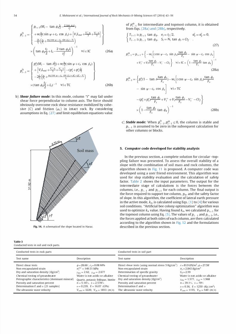
7232019 Slope Stability 201312020
httpslidepdfcomreaderfullslope-stability-201312020 1214
p f t i 1 frac14
pi thorn 1ethM i tan ϕdt f 2
2 tan ϕdI it 2 f
THORN
thornwihi
2 eth sin ψ thornc e cos β eTHORN thorn V iLout thornV thorni yi
3 thornV i z i
3
h i2I i
t f st
F sthorn
wi eth cos ψ c e sin β eTHORN V it f
8gtgtgtgtgtltgtgtgtgtgt
9gtgtgtgtgt=gtgtgtgtgt
tan ϕd
t f
2thornLi
2 tan ϕdI i
t 2 f
1
8 iAIC eth26aTHORN
p f t i 1 frac14
pns ethM i tan δ
t f 2THORN thornwi
hi
2 eth sin ψ thornc e cos β eTHORN
thorn V iLout thornV thorni yi
3 thornV i z i
3
h ieth ps
s thorn pc s THORN
t f 2
2I it f
st
F sthorn
wieth cos ψ c e sin β e THORN thorn pss thorn pc
s V it f
8gtgtgtgtltgtgtgtgt
9gtgtgtgt=gtgtgtgt
eth tan ϕd
t f
2thorn LiTHORN
1 8 iATC eth26bTHORN
b) Shear failure mode In this mode column ldquoirdquo may fail undershear force perpendicular to column axis The force shouldobviously overcome rock shear resistance mobilized by cohe-sive (C ) and friction (φr ) in intact rock By consideringassumptions in Eq (27) and limit equilibrium equations value
of pshi 1 for intermediate and topmost column it is obtained
from Eqs (28a) and (28b) respectively
T i thorn 1 ffi pi thorn 1 tan ϕd ei frac14 t f =2 ai x frac14 ai
y frac14 0
T i 1 ffi pi 1 tan ϕd S i frac14 N i tan ϕr thorn Ct f
(
eth27THORN
pshi 1 frac14 pi thorn 1 thorn wi eth cos ψ c e sin β eTHORN
tan ϕr
F s sin ψ c e cos β e
thorn V thorni thorn V itan ϕr
F s V i Ct f
) 8 iA IC 1
tan ϕr
F stan ϕd
1
eth28aTHORN
pshi 1 frac14 pn
s eth1 tan δ tan ϕr
F sTHORN wi eth cos ψ c e sin β eTHORN
tan ϕr
F s
sin ψ c e cos β e
8 iATC
eth pss thorn pc
s THORNtan ϕr
F sthorn V thorni thornV i
tan ϕr
F sV i Ct f
)
1 tan ϕr
F stan ϕd
1
eth28bTHORN
c) Stable mode When p f t i 1 psh
i 1r0 the column is stable and pi 1 is assumed to be zero in the subsequent calculation forother columns or blocks
5 Computer code developed for stability analysis
In the previous section a complete solution for circularndashtop-pling failure was presented To assess the overall stability of aslope with the combination of soil mass and rock columns thealgorithm shown in Fig 11 is proposed A computer code wasdeveloped using a user friend environment This algorithm wasused for slop stability evaluation and the calculation of safetyfactor Table 2 shows the input parameters The output for theintermediate stage of calculations is the forces between thecolumns ie pi 1 and pi thorn 1 for each column The 1047297nal output isthe force required to support toe column p0 and the safety factorof slope In this algorithm the coef 1047297cient of lateral earth pressurein the active mode ka is calculated using Eqs (1) to (4) for varioussoil conditions ldquoArti1047297cial bee colony optimizationrdquo algorithm wasused to optimize ka value Having found ka we calculated pi thorn 1 forthe topmost column using Eq (5) The values of pi 1 and pi thorn 1 iethe forces applied at both sides of each column are then calculatedaccording to the algorithm shown in Fig 12 and the formulationsdescribed in the previous section
53
25
45
6 7 0 m
3 1 9
2 m
77
Soil mass
Fig 14 A schematicof the slope located in Haraz
Table 3
Conducted tests in soil and rock parts
Conducted tests in rock parts Conducted tests in soil part
Test name Description Test name Description
Direct shear tests ϕfrac1428661 c jfrac14008 MPa Direct shear tests (using normal stress 5 Kgcm3) c frac14819 KNm 2 ϕfrac1427581Non-encapsulated strain s
avec frac14 14951 MPa Non-encapsulated strain sc frac142843 Kgcm 3
Dry and saturation density (Kgcm 3) γ dry frac14 262 γ sat frac14 2677 Determinat ion of speci1047297c gravity GS frac14259
Chemical testing of groundwater Water is not acidic or alkaline Chemical testing of groundwater Water is not acidic or alkalinePetrographic characteristics (dominant mineral) Quartz potassic feldspar biotite Dry and saturation density (Kgcm 3) γ dry frac14 1577 γ sat frac14 1968
Porosity and saturation percent n frac14 516 s frac14 2578 Porosity and saturation percent n frac14 391 s frac14 70Determination E and υ (21 samples) υ frac14 0239 E frac14 1607 ethGPaTHORN Determination E and υ υ frac14 036 E frac14 1250 ethKg =cm2THORN
The ultrasonic wave velocity V com frac14 3220 V sh frac14 1853 ethm=sTHORN The ultrasonic wave velocity V com frac14 1155 V sh frac14 540 ethm=sTHORN
E Mohtarami et al International Journal of Rock Mechanics amp Mining Sciences 67 (2014) 43ndash56 54
7232019 Slope Stability 201312020
httpslidepdfcomreaderfullslope-stability-201312020 1314
By 1047297nding p0 (ie p i 1 for toe column) the stability of a slopesubject to circular-toppling failure can be judged as follows
p04 0 Unstable
p0 frac14 0 Limit equilibrium condition
p0o 0 Stable
8gtlt
gt It should be noted that safety factor ethF sTHORN is set equal to 1 for
1047297nding p0 at the initial stage If p0 frac14 0 at the initial calculations theslope is at equilibrium state and calculation is no longer necessaryIf p040 then the slope is unstable and the value of F s is reducedgradually until p0 frac14 0 The 1047297nal calculated F s is the actual safetyfactor of the slope Similarly if p0o0 then the slope is stable Theactual safety factor is found by increasing the amount of F s incalculation loop till p0 frac14 0 The 1047297nal calculated F s is the actualsafety factor of the slope The increase or reduction of F s anddetermination of the optimum value are done using the arti1047297cialbee colony algorithm (Fig 11) In the previous studies the blockshave been alternately considered in blocky or 1047298exural topplingmode The proposed solution in this paper freely allows for anycombination
6 Case study
A real case including a slope subject to failure was studiedusing the proposed method This slope is located in Vana villagealong Haraz road in northern Iran 70 km from Amol city Theslope consists of rhyolite tuff overlooking Haraz road with thepotential of toppling Fig 13 shows the general view of the slopeand Fig 14 depicts the slope schematically As can be seen in these1047297gures a large amount of sediments and volcanic debris isdumped on the top of slope behind the rock columns This massgenerates the soil active pressure Ongoing erosion of the sedi-ments and volcanic rock not only increases the active pressure butalso causes the rock falls which have already caused some
accidents and injuries Due to the concern of possible failure of block rocks a research project was organized by research instituteof the Ministry of Roads and Urban Development for the evalua-tion of the general stability of the slope The existing residentialand commercial buildings next to this slope helped authoritiesaccept the minimum F S to be equal to 155
A number of exploration drillings were performed within theslope to obtain the geo-mechanical properties Moreover observa-tions were made through the existing tunnel of an old coal mine inthe area Table 3 shows the main obtained data used for this study
The stability of the slope in Vana village was analyzed using theproposed method and the developed code The code shows severalitems as outputs (a) Geometry and geo-mechanical parameterswhich are partially inputted by the user and partially calculated
by the code (b) forces between the columns ( pi1 and p ithorn1) and
possible failure mode of each block and (c) safety factor andstability state of the slope Furthermore we can obtain the appliedforce on topmost block by the soil by running the computer code
The analysis revealed that safety factor for this slope was equalto 164 for combined circularndashtoppling failure which was higherthan the acceptable 1047297gure by authorities The slope was found atstable state however it should be noted that due to futureerosions soil value and active soil pressure may increase during
the years Thus update evaluation may be necessary from time totime Moreover despite the general stability of this slope localrock falls can still happen Fig 15 shows potential rock falls due toerosion resulted by the running water
7 Conclusions
Different types of the toppling failure are still a major instabil-ity for slopes in nature and slopes all over the world Combinedcircularndashtoppling failure is a kind of instability not studied beforein details In this paper a complete solution was presented for thistype of failure A new formulation was developed to investigatethe stability of slope components (the soil and rock part)
The developed solution in this paper has taken all the effectiveparameters (external forces water pressure and earthquake) intoaccount Every column can be in any mode of failure including astable mode The presented solution unstable forms were widelyanalyzed from the point of limit equilibrium method in discontin-uous rock and allowed for any combination of failure in thecolumns ie failure mode of each column could be different withthe mode of neighboring columns Another advantage of theproposed solution is that the topmost column can have anyinclination and the applied force by soil mass can be calculatedby plasticity theory which has good accuracy
A computer code was developed to ease the use of the proposedsolution The code was simple and fast it gave the 1047297nal state of stability as well as safety factor of the slope By using this code the
effect of different parameters (like block inclination friction etc) onstability can be simply and quickly studied Such a study can helpthe users decide on the necessary measures for making the slopemore stable
References
[1] Goodman RE Bray JW Toppling of rock slopes In Boulder CO Proceedings of the specialty conference on rock engineering for foundations and slopesNew York American Society of Civil Engineers 15ndash18 August 1976 p 201ndash23
[2] Amini M Majdi A Veshadi MA Stability analysis of rock slopes against blockndash
1047298exure toppling failure Int J Rock Mech Rock Eng 201245(4)519ndash32[3] Collin A Recherches expeacuterimentaux sur les glissements spontaneacutes des terrains
argileux Paris Carilian-Goeurley et Dalmont [4] Taylor DW Stability of Earth slopes J Boston Soc Civ Eng 19371337ndash86
[5] Willie DC Mah CW Rock slope engineering (civil and mining) 4th EditionUK Spoon Press London Taylor and Francis Group 2004[6] Bishop AW The use of the slip circle in the stability analysis of slopes
Geacuteotechnique 195557ndash17[7] Nonveiller E The stability analysis of slopes with a slide surface of general
shape Proc 6th Int Conf Soil Mech Found Eng Montreal 1965279ndash93[8] Morgenstern NR Price VE The analysis of the stability of generalised slip
surfaces Geacuteotechnique 19651579ndash93[9] Chen Z Morgenstern NR Extensions to the generalized method of slices for
stability analysis Can Geotech J 198320(1)104ndash19[10] Muller L New considerations of the Vaiont slide Felsmech Engenieurgeologie
19686(1)1ndash91[11] Ashby J Sliding and toppling modes of failure in models and jointed rock
slopes [MSc thesis] London United Kingdom London University ImperialCollege 1971
[12] Hofmann H Kinematische modellstudien zum boschungs-problem in regal-massig geklufteten medien [PhD thesis] Karlsruhe Germany University of Karlsruhe 1972
[13] De Freitas MH Watters RJ Some 1047297eld examples of toppling failure Geacuteotech-
nique 197323495ndash514
Fig 15 Erosion and destructionwithin rock section of the slope
E Mohtarami et al International Journal of Rock Mechanics amp Mining Sciences 67 (2014) 43ndash56 55
7232019 Slope Stability 201312020
httpslidepdfcomreaderfullslope-stability-201312020 1414
[14] Whyte RJA Study of progressive hanging wall caving at chambishi coppermine in Zambia using the base friction model concept [MSc thesis] LondonUnited Kingdom London University Imperial College 1973
[15] Soto CA Comparative study of slope modelling techniques for fracturedground [MSc thesis] London United Kingdom London University ImperialCollege 1974
[16] Zanbak C Design charts for rock slopes susceptible to toppling J Geotech EngASCE 19831091039ndash62
[17] Goodman R Shi G Block theory and its application to rock engineeringEnglewood Cliffs New Jersey Prentice-Hall 1985 338
[18] Aydan Ouml Shimizu Y Ichikawa Y The effective failure modes and stability of slopes
in rock mass with two discontinuity sets Rock Mech Rock Eng 198922(3)163ndash88[19] Davies JN Smith PLP Flexural toppling of siltstones during a temporary
excavation for a bridge foundation in North Devon In Hadson JA editorComprehensive rock engineering Oxford Pergamon Press 1993 p 759ndash75
[20] Zaruba Q Mencl V Engineering geology Amsterdam Elsevier 1976[21] Aydan Ouml Kawamoto T Stability of slopes and underground openings against
1047298exural toppling and their stabilization Rock Mech Rock Eng 199225(3)143ndash65[22] Adhikary DP Dyskin AV Jewell RJ Modeling of 1047298exural toppling failures of
rock slopes In Proceedings of the eighth international congress rockmechanics Tokyo 1995 p 25ndash9
[23] Adhikary DP Dyskin AV Jewell RJ Stewart DP A study of the mechanism of 1047298exural toppling failure of rock slopes Rock Mech Rock Eng 199730(2)75ndash93
[24] Adhikary DP Dyskin AV Modeling of progressive and instantaneous failure of foliated rock slopes Rock Mech Rock Eng 200740(4)349ndash62
[25] Aydan Ouml Amini M An experimental study on rock slopes against 1047298exuraltoppling failure under dynamic loading and some theoretical considerationsfor its stability assessment J Sch Mar Sci Technol 20097(2)25 ndash40
[26] Braja MD Principles of geotechnical engineering 7th edition Stamford USACengage learning 2010
[27] Lambe TW Whitman RV Soil mechanics Massachusetts institute of technol-ogy Cambridge Massachusetts John Wiley and Sons 1969
[28] Caquot A Kerisel J Table for the calculation of passive pressure activepressure and bearing capacity of foundations (trans by MA Bec London)Paris Gauthier-Villars 1948
[29] Janbu N 4thEarth pressure and bearing capacity calculations by generalizedprocedure of slices Vol 2 London ICSMFE 1957 207ndash12
[30] Shields DH Tolunay AZ Passive pressure coef 1047297cients by method of slices JSMFD AS CE 197399(SM 12)S1043ndash53
[31] Sokolovski VV Statics of granular media Oxford Pergamon Press 1965 [32] Behnia K Tabatabai AM Soil mechanics 2nd Ed Tehran Tehran University
Press 1987[33] Chen WF Rosenfarb JL Limit analysis solutions of Earth pressure problems
Jpn S oc Soil Mech Found Eng 197313(4)45ndash60[34] PLAXIS V8 Finite element code for soil and rock analyses PLAXIS-3D
Reference manual Edited by Brinkgreve et al DUT The Netherlands langwwwplaxisnl2004rang
E Mohtarami et al International Journal of Rock Mechanics amp Mining Sciences 67 (2014) 43ndash56 56
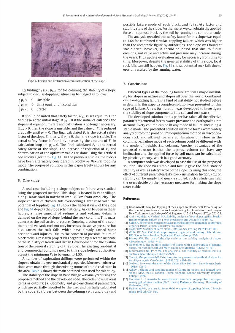
7232019 Slope Stability 201312020
httpslidepdfcomreaderfullslope-stability-201312020 1314
By 1047297nding p0 (ie p i 1 for toe column) the stability of a slopesubject to circular-toppling failure can be judged as follows
p04 0 Unstable
p0 frac14 0 Limit equilibrium condition
p0o 0 Stable
8gtlt
gt It should be noted that safety factor ethF sTHORN is set equal to 1 for
1047297nding p0 at the initial stage If p0 frac14 0 at the initial calculations theslope is at equilibrium state and calculation is no longer necessaryIf p040 then the slope is unstable and the value of F s is reducedgradually until p0 frac14 0 The 1047297nal calculated F s is the actual safetyfactor of the slope Similarly if p0o0 then the slope is stable Theactual safety factor is found by increasing the amount of F s incalculation loop till p0 frac14 0 The 1047297nal calculated F s is the actualsafety factor of the slope The increase or reduction of F s anddetermination of the optimum value are done using the arti1047297cialbee colony algorithm (Fig 11) In the previous studies the blockshave been alternately considered in blocky or 1047298exural topplingmode The proposed solution in this paper freely allows for anycombination
6 Case study
A real case including a slope subject to failure was studiedusing the proposed method This slope is located in Vana villagealong Haraz road in northern Iran 70 km from Amol city Theslope consists of rhyolite tuff overlooking Haraz road with thepotential of toppling Fig 13 shows the general view of the slopeand Fig 14 depicts the slope schematically As can be seen in these1047297gures a large amount of sediments and volcanic debris isdumped on the top of slope behind the rock columns This massgenerates the soil active pressure Ongoing erosion of the sedi-ments and volcanic rock not only increases the active pressure butalso causes the rock falls which have already caused some
accidents and injuries Due to the concern of possible failure of block rocks a research project was organized by research instituteof the Ministry of Roads and Urban Development for the evalua-tion of the general stability of the slope The existing residentialand commercial buildings next to this slope helped authoritiesaccept the minimum F S to be equal to 155
A number of exploration drillings were performed within theslope to obtain the geo-mechanical properties Moreover observa-tions were made through the existing tunnel of an old coal mine inthe area Table 3 shows the main obtained data used for this study
The stability of the slope in Vana village was analyzed using theproposed method and the developed code The code shows severalitems as outputs (a) Geometry and geo-mechanical parameterswhich are partially inputted by the user and partially calculated
by the code (b) forces between the columns ( pi1 and p ithorn1) and
possible failure mode of each block and (c) safety factor andstability state of the slope Furthermore we can obtain the appliedforce on topmost block by the soil by running the computer code
The analysis revealed that safety factor for this slope was equalto 164 for combined circularndashtoppling failure which was higherthan the acceptable 1047297gure by authorities The slope was found atstable state however it should be noted that due to futureerosions soil value and active soil pressure may increase during
the years Thus update evaluation may be necessary from time totime Moreover despite the general stability of this slope localrock falls can still happen Fig 15 shows potential rock falls due toerosion resulted by the running water
7 Conclusions
Different types of the toppling failure are still a major instabil-ity for slopes in nature and slopes all over the world Combinedcircularndashtoppling failure is a kind of instability not studied beforein details In this paper a complete solution was presented for thistype of failure A new formulation was developed to investigatethe stability of slope components (the soil and rock part)
The developed solution in this paper has taken all the effectiveparameters (external forces water pressure and earthquake) intoaccount Every column can be in any mode of failure including astable mode The presented solution unstable forms were widelyanalyzed from the point of limit equilibrium method in discontin-uous rock and allowed for any combination of failure in thecolumns ie failure mode of each column could be different withthe mode of neighboring columns Another advantage of theproposed solution is that the topmost column can have anyinclination and the applied force by soil mass can be calculatedby plasticity theory which has good accuracy
A computer code was developed to ease the use of the proposedsolution The code was simple and fast it gave the 1047297nal state of stability as well as safety factor of the slope By using this code the
effect of different parameters (like block inclination friction etc) onstability can be simply and quickly studied Such a study can helpthe users decide on the necessary measures for making the slopemore stable
References
[1] Goodman RE Bray JW Toppling of rock slopes In Boulder CO Proceedings of the specialty conference on rock engineering for foundations and slopesNew York American Society of Civil Engineers 15ndash18 August 1976 p 201ndash23
[2] Amini M Majdi A Veshadi MA Stability analysis of rock slopes against blockndash
1047298exure toppling failure Int J Rock Mech Rock Eng 201245(4)519ndash32[3] Collin A Recherches expeacuterimentaux sur les glissements spontaneacutes des terrains
argileux Paris Carilian-Goeurley et Dalmont [4] Taylor DW Stability of Earth slopes J Boston Soc Civ Eng 19371337ndash86
[5] Willie DC Mah CW Rock slope engineering (civil and mining) 4th EditionUK Spoon Press London Taylor and Francis Group 2004[6] Bishop AW The use of the slip circle in the stability analysis of slopes
Geacuteotechnique 195557ndash17[7] Nonveiller E The stability analysis of slopes with a slide surface of general
shape Proc 6th Int Conf Soil Mech Found Eng Montreal 1965279ndash93[8] Morgenstern NR Price VE The analysis of the stability of generalised slip
surfaces Geacuteotechnique 19651579ndash93[9] Chen Z Morgenstern NR Extensions to the generalized method of slices for
stability analysis Can Geotech J 198320(1)104ndash19[10] Muller L New considerations of the Vaiont slide Felsmech Engenieurgeologie
19686(1)1ndash91[11] Ashby J Sliding and toppling modes of failure in models and jointed rock
slopes [MSc thesis] London United Kingdom London University ImperialCollege 1971
[12] Hofmann H Kinematische modellstudien zum boschungs-problem in regal-massig geklufteten medien [PhD thesis] Karlsruhe Germany University of Karlsruhe 1972
[13] De Freitas MH Watters RJ Some 1047297eld examples of toppling failure Geacuteotech-
nique 197323495ndash514
Fig 15 Erosion and destructionwithin rock section of the slope
E Mohtarami et al International Journal of Rock Mechanics amp Mining Sciences 67 (2014) 43ndash56 55
7232019 Slope Stability 201312020
httpslidepdfcomreaderfullslope-stability-201312020 1414
[14] Whyte RJA Study of progressive hanging wall caving at chambishi coppermine in Zambia using the base friction model concept [MSc thesis] LondonUnited Kingdom London University Imperial College 1973
[15] Soto CA Comparative study of slope modelling techniques for fracturedground [MSc thesis] London United Kingdom London University ImperialCollege 1974
[16] Zanbak C Design charts for rock slopes susceptible to toppling J Geotech EngASCE 19831091039ndash62
[17] Goodman R Shi G Block theory and its application to rock engineeringEnglewood Cliffs New Jersey Prentice-Hall 1985 338
[18] Aydan Ouml Shimizu Y Ichikawa Y The effective failure modes and stability of slopes
in rock mass with two discontinuity sets Rock Mech Rock Eng 198922(3)163ndash88[19] Davies JN Smith PLP Flexural toppling of siltstones during a temporary
excavation for a bridge foundation in North Devon In Hadson JA editorComprehensive rock engineering Oxford Pergamon Press 1993 p 759ndash75
[20] Zaruba Q Mencl V Engineering geology Amsterdam Elsevier 1976[21] Aydan Ouml Kawamoto T Stability of slopes and underground openings against
1047298exural toppling and their stabilization Rock Mech Rock Eng 199225(3)143ndash65[22] Adhikary DP Dyskin AV Jewell RJ Modeling of 1047298exural toppling failures of
rock slopes In Proceedings of the eighth international congress rockmechanics Tokyo 1995 p 25ndash9
[23] Adhikary DP Dyskin AV Jewell RJ Stewart DP A study of the mechanism of 1047298exural toppling failure of rock slopes Rock Mech Rock Eng 199730(2)75ndash93
[24] Adhikary DP Dyskin AV Modeling of progressive and instantaneous failure of foliated rock slopes Rock Mech Rock Eng 200740(4)349ndash62
[25] Aydan Ouml Amini M An experimental study on rock slopes against 1047298exuraltoppling failure under dynamic loading and some theoretical considerationsfor its stability assessment J Sch Mar Sci Technol 20097(2)25 ndash40
[26] Braja MD Principles of geotechnical engineering 7th edition Stamford USACengage learning 2010
[27] Lambe TW Whitman RV Soil mechanics Massachusetts institute of technol-ogy Cambridge Massachusetts John Wiley and Sons 1969
[28] Caquot A Kerisel J Table for the calculation of passive pressure activepressure and bearing capacity of foundations (trans by MA Bec London)Paris Gauthier-Villars 1948
[29] Janbu N 4thEarth pressure and bearing capacity calculations by generalizedprocedure of slices Vol 2 London ICSMFE 1957 207ndash12
[30] Shields DH Tolunay AZ Passive pressure coef 1047297cients by method of slices JSMFD AS CE 197399(SM 12)S1043ndash53
[31] Sokolovski VV Statics of granular media Oxford Pergamon Press 1965 [32] Behnia K Tabatabai AM Soil mechanics 2nd Ed Tehran Tehran University
Press 1987[33] Chen WF Rosenfarb JL Limit analysis solutions of Earth pressure problems
Jpn S oc Soil Mech Found Eng 197313(4)45ndash60[34] PLAXIS V8 Finite element code for soil and rock analyses PLAXIS-3D
Reference manual Edited by Brinkgreve et al DUT The Netherlands langwwwplaxisnl2004rang
E Mohtarami et al International Journal of Rock Mechanics amp Mining Sciences 67 (2014) 43ndash56 56