slope stability analysis in rocks
TRANSCRIPT

SLOPE STABILITY ANALYSIS IN ROCKS
Part 2 - Wedge failure
1
Created By: Shaloo Puri
Website: www.geotechnicaldesigns.com.au
Email id : [email protected]
WhatsApp: +61452075310
MEP/E&M Expert: Mukesh Singh
Website : www.foxcons.com
Email id: [email protected]
SLOPE STABILITY ANALYSIS IN ROCKS
www.geotechnicaldesigns.com.au
2
This Presentation on Slope stability analysis is divided into three parts. This
presentation we will cover Wedge Failure only.
1. Planar Failure
2. Wedge Failure
3. Failure in Rock mass
The direction and size of these failures depend upon the following parameters:
1. Joint sets
2. Joints dip and dip direction
3. Joints frictional properties (c and )4. Dip and dip direction of slopes face
KINEMATIC ANALYSIS
www.geotechnicaldesigns.com.au
3
Kinematic Analysis is very important method for determining the mode of
failures.
This method also determines which joint sets will have planar failure or
wedge failure or toppling failure with a particular slope face dip direction.
We use Dips software (Rocscience) for determining the mode of failures.
Input dip and dip direction of all the joints, separate poles will develop for
each joint sets.
KINEMATIC ANALYSIS – WEDGE FAILURE
www.geotechnicaldesigns.com.au
4
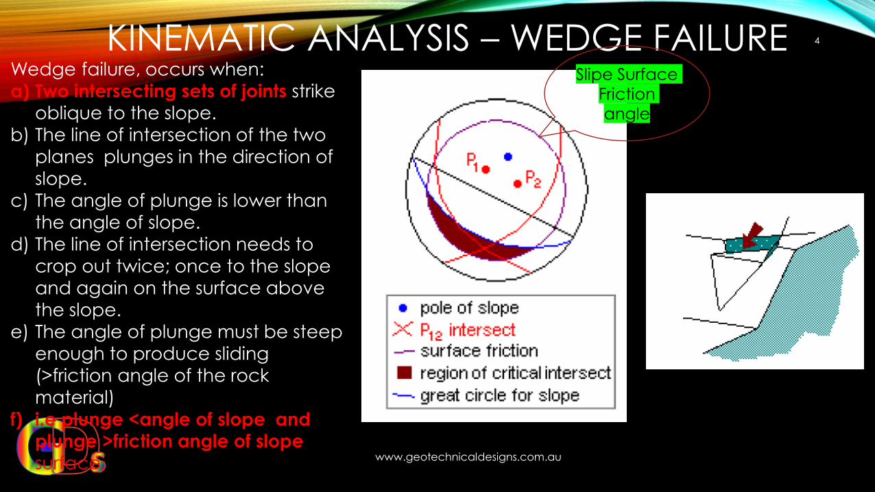
Wedge failure, occurs when:
a) Two intersecting sets of joints strike
oblique to the slope.
b) The line of intersection of the two
planes plunges in the direction of
slope.
c) The angle of plunge is lower than
the angle of slope.
d) The line of intersection needs to
crop out twice; once to the slope
and again on the surface above
the slope.
e) The angle of plunge must be steep
enough to produce sliding
(>friction angle of the rock material)
f) i.e plunge <angle of slope and plunge >friction angle of slope
surface.
Slipe Surface
Friction
angle
WEDGE FAILURE
www.geotechnicaldesigns.com.au
5
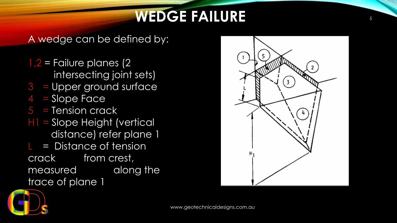
A wedge can be defined by:
1,2 = Failure planes (2
intersecting joint sets)
3 = Upper ground surface
4 = Slope Face
5 = Tension crack
H1 = Slope Height (vertical
distance) refer plane 1
L = Distance of tension
crack from crest,
measured along the
trace of plane 1
SOFTWARE - SWEDGE
www.geotechnicaldesigns.com.au
6
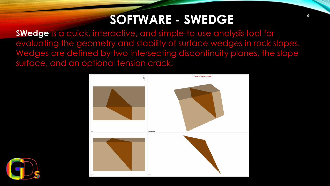
SWedge is a quick, interactive, and simple-to-use analysis tool for
evaluating the geometry and stability of surface wedges in rock slopes.
Wedges are defined by two intersecting discontinuity planes, the slope
surface, and an optional tension crack.
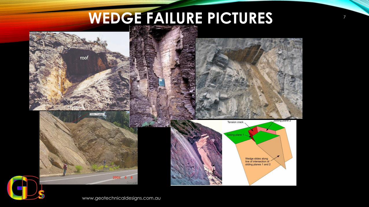
WEDGE FAILURE PICTURES
www.geotechnicaldesigns.com.au
7
SOFTWARE - SWEDGE
www.geotechnicaldesigns.com.au
8
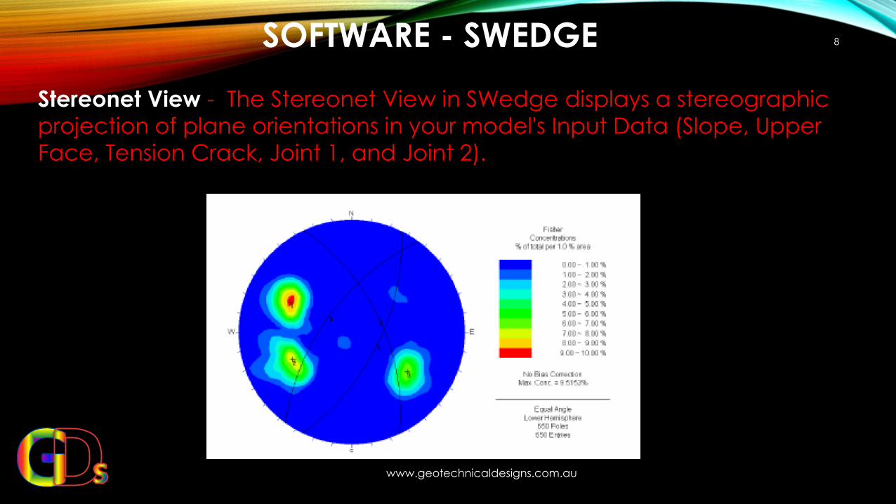
Stereonet View - The Stereonet View in SWedge displays a stereographic
projection of plane orientations in your model's Input Data (Slope, Upper
Face, Tension Crack, Joint 1, and Joint 2).
DECIDING FACTORS FOR SLOPE STABILITY
www.geotechnicaldesigns.com.au
9
The factor which determines the Failure of Wedge are as follows:
1. Water Pressure in joints.
2. Shear Parameters of Slip plane.
3. Seismicity
DECIDING FACTORS FOR SLOPE STABILITY
www.geotechnicaldesigns.com.au
10
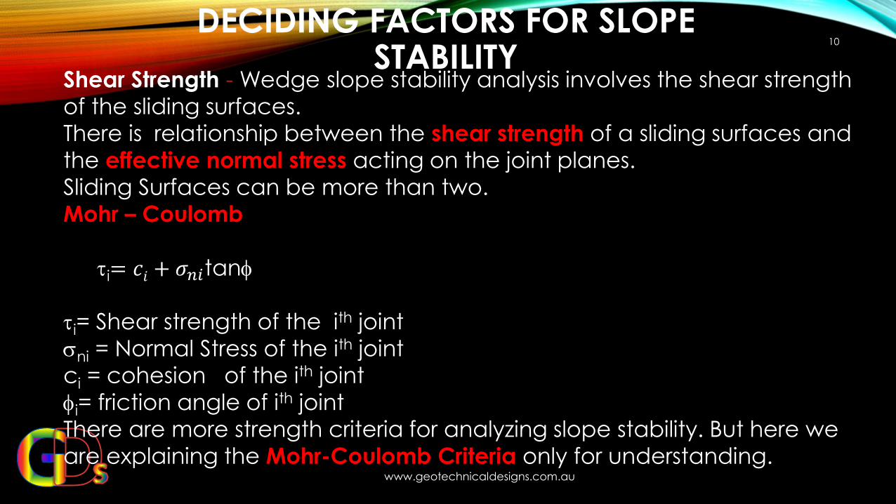
Shear Strength - Wedge slope stability analysis involves the shear strength
of the sliding surfaces.
There is relationship between the shear strength of a sliding surfaces and
the effective normal stress acting on the joint planes.
Sliding Surfaces can be more than two.
Mohr – Coulomb
i= 𝑐𝑖 + 𝜎𝑛𝑖tan
i= Shear strength of the ith joint
ni = Normal Stress of the ith joint
ci = cohesion of the ith joint
i= friction angle of ith joint
There are more strength criteria for analyzing slope stability. But here we
are explaining the Mohr-Coulomb Criteria only for understanding.
SWEDGE– EXAMPLE 1
www.geotechnicaldesigns.com.au
11
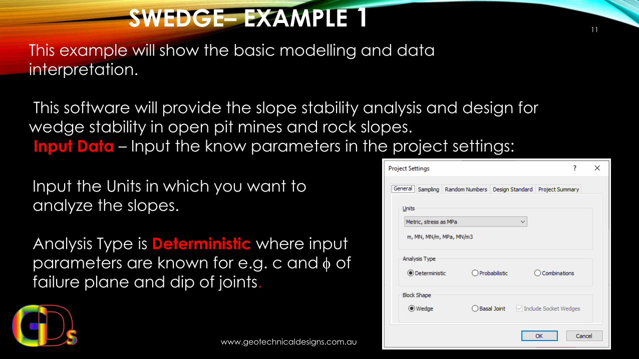
This example will show the basic modelling and data
interpretation.
This software will provide the slope stability analysis and design for
wedge stability in open pit mines and rock slopes.
Input Data – Input the know parameters in the project settings:
Input the Units in which you want to
analyze the slopes.
Analysis Type is Deterministic where input
parameters are known for e.g. c and of
failure plane and dip of joints.
SWEDGE – INPUTS
www.geotechnicaldesigns.com.au12
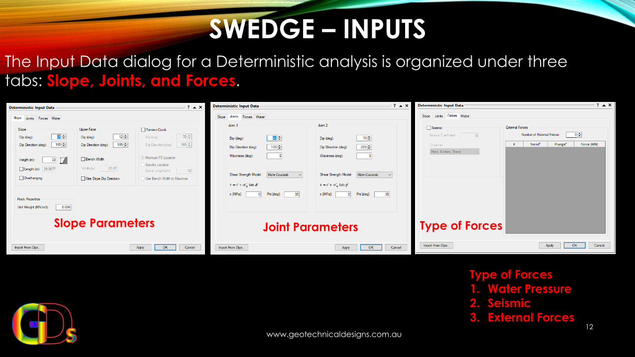
The Input Data dialog for a Deterministic analysis is organized under three
tabs: Slope, Joints, and Forces.
Slope Parameters Joint Parameters Type of Forces
Type of Forces
1. Water Pressure
2. Seismic
3. External Forces
3D PERSPECTIVE VIEW - INTERPRETATION
www.geotechnicaldesigns.com.au
13
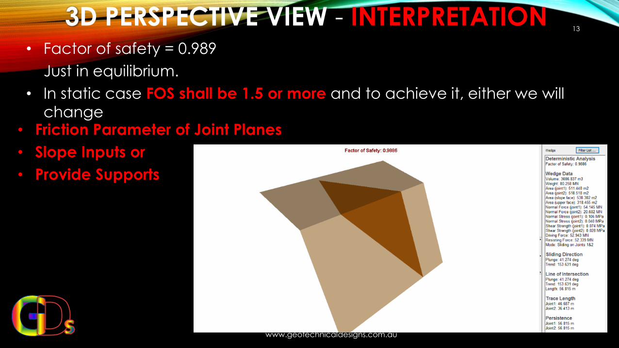
• Factor of safety = 0.989
Just in equilibrium.
• In static case FOS shall be 1.5 or more and to achieve it, either we will
change • Friction Parameter of Joint Planes
• Slope Inputs or
• Provide Supports
CHANGE SLOPE PARAMETERS TO INCREASE FOS OF SLOPE STABILITY
www.geotechnicaldesigns.com.au
14
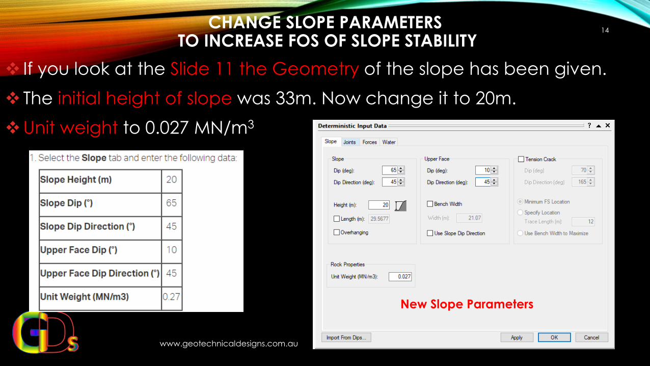
❖ If you look at the Slide 11 the Geometry of the slope has been given.
❖ The initial height of slope was 33m. Now change it to 20m.
❖Unit weight to 0.027 MN/m3
New Slope Parameters
INCREASE JOINTS PARAMETERS TO INCREASE FOS OF SLOPE STABILITY
www.geotechnicaldesigns.com.au 15
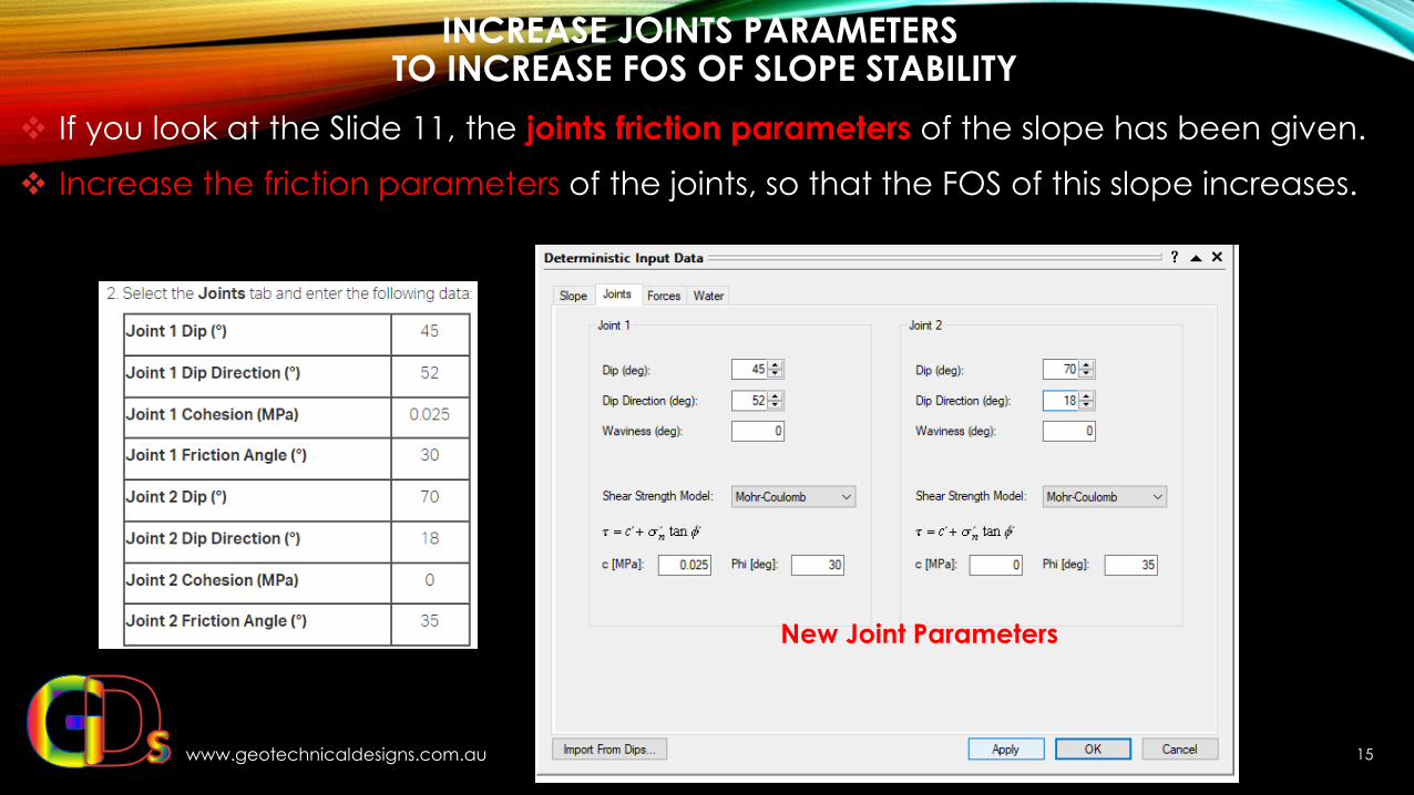
❖ If you look at the Slide 11, the joints friction parameters of the slope has been given.
❖ Increase the friction parameters of the joints, so that the FOS of this slope increases.
New Joint Parameters
FACTOR OF SAFETY AFTER CHANGES
www.geotechnicaldesigns.com.au
16
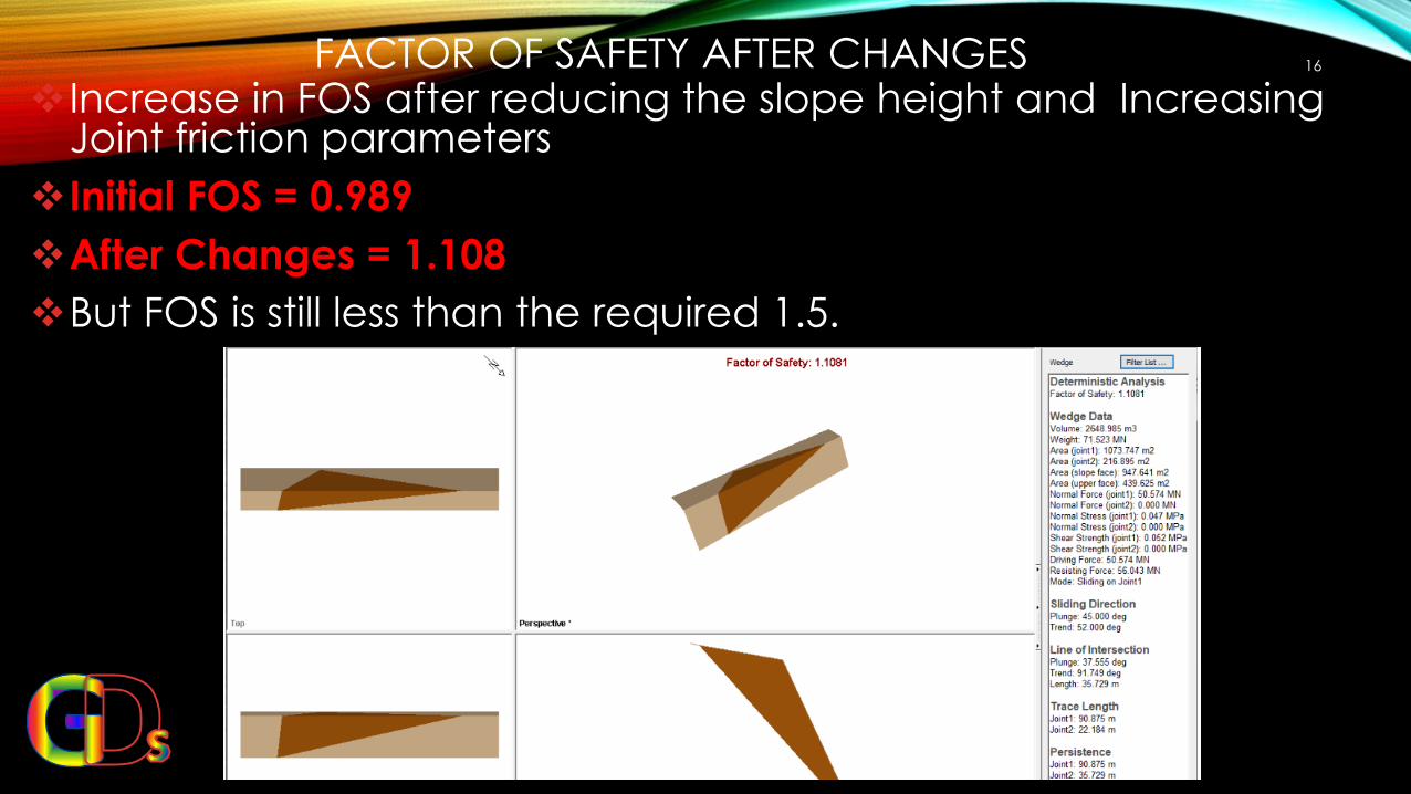
❖ Increase in FOS after reducing the slope height and Increasing Joint friction parameters
❖Initial FOS = 0.989
❖After Changes = 1.108
❖But FOS is still less than the required 1.5.
WATER PRESSURE
www.geotechnicaldesigns.com.au
17
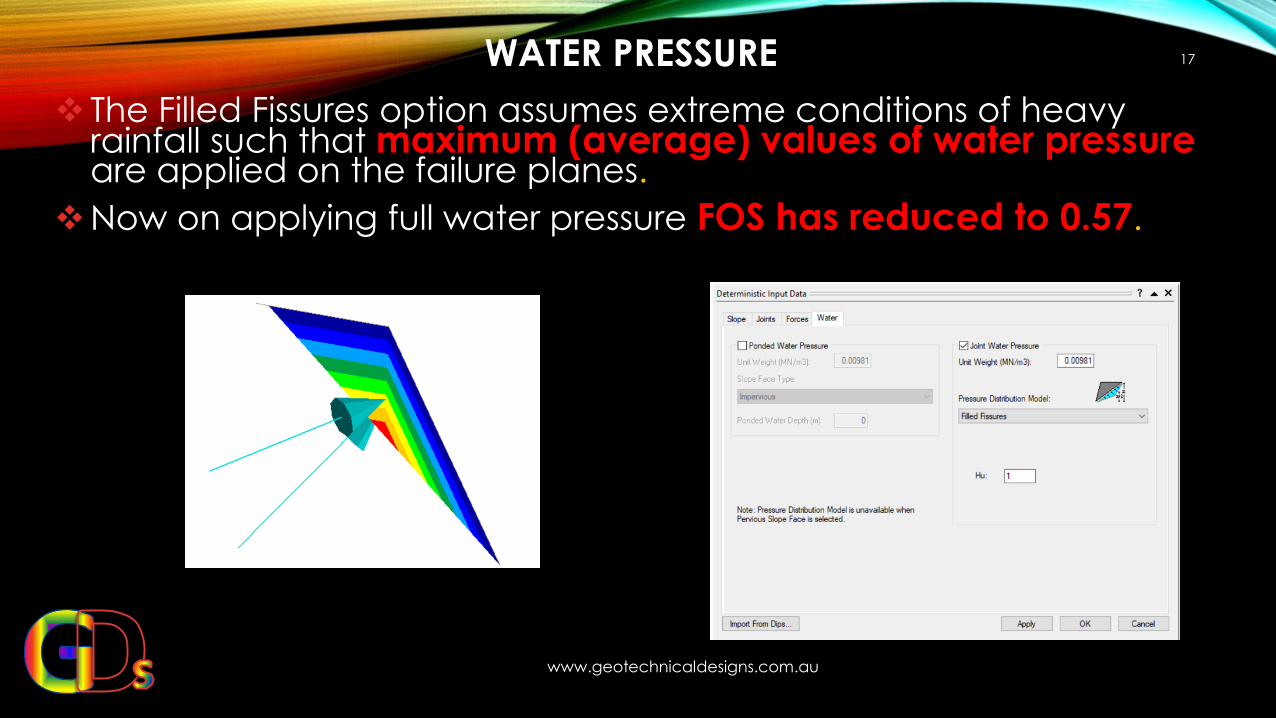
❖ The Filled Fissures option assumes extreme conditions of heavy rainfall such that maximum (average) values of water pressureare applied on the failure planes.
❖Now on applying full water pressure FOS has reduced to 0.57.
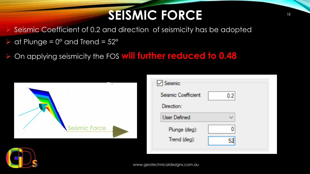
SEISMIC FORCE
www.geotechnicaldesigns.com.au
18
➢ Seismic Coefficient of 0.2 and direction of seismicity has be adopted
➢ at Plunge = 0° and Trend = 52°
➢ On applying seismicity the FOS will further reduced to 0.48
Seismic Force
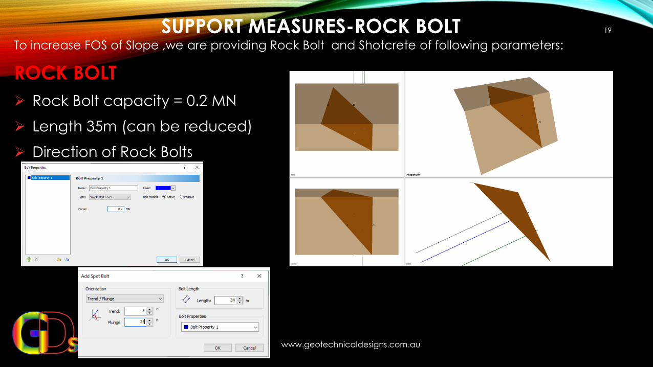
SUPPORT MEASURES-ROCK BOLT
www.geotechnicaldesigns.com.au
19
To increase FOS of Slope ,we are providing Rock Bolt and Shotcrete of following parameters:
ROCK BOLT
➢ Rock Bolt capacity = 0.2 MN
➢ Length 35m (can be reduced)
➢ Direction of Rock Bolts
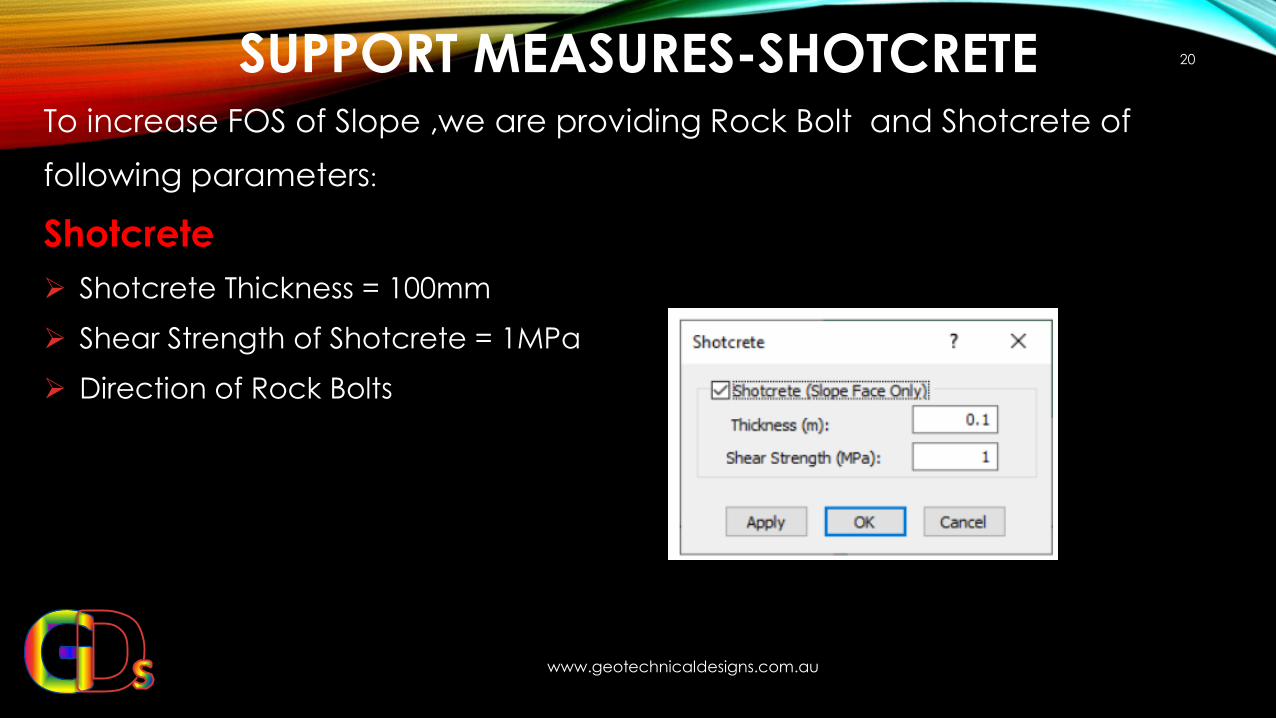
SUPPORT MEASURES-SHOTCRETE
www.geotechnicaldesigns.com.au
20
To increase FOS of Slope ,we are providing Rock Bolt and Shotcrete of
following parameters:
Shotcrete
➢ Shotcrete Thickness = 100mm
➢ Shear Strength of Shotcrete = 1MPa
➢ Direction of Rock Bolts
FACTOR OF SAFETY AFTER SUPPORT MEASURES (FOS 1.525)
www.geotechnicaldesigns.com.au
21
Factor of safety increase from 0.48 to 1.525 after applying
➢ Rock Bolts
➢ Shotcrete
Therefore it is very important to provide support system to counter act forces
➢ Water Pressures
➢ Seismicity and
➢ Sliding force of Wedge

THANKS FOR WATCHING PRESENTATION
22
Created By: Shaloo Puri
Website: www.geotechnicaldesigns.com.au
Email id : [email protected]
WhatsApp: +61452075310