slot tech feature article tovis part 4 - the microcontroller
TRANSCRIPT
Slot Tech MagazineApril 2005 Page 31
TOVIS An Introduction to Digital Monitors
Slot Tech Feature Article
Part 4 - The Microcontroller
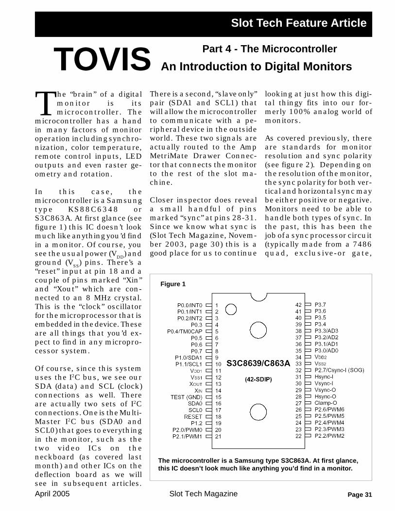
The microcontroller is a Samsung type S3C863A. At first glance,this IC doesn’t look much like anything you’d find in a monitor.
Figure 1
The “brain” of a digitalmonitor is itsmicrocontroller. The
microcontroller has a handin many factors of monitoroperation including synchro-nization, color temperature,remote control inputs, LEDoutputs and even raster ge-ometry and rotation.
In this case, themicrocontroller is a Samsungtype KS88C6348 orS3C863A. At first glance (seefigure 1) this IC doesn’t lookmuch like anything you’d findin a monitor. Of course, yousee the usual power (VDD) andground (VSS) pins. There’s a“reset” input at pin 18 and acouple of pins marked “Xin”and “Xout” which are con-nected to an 8 MHz crystal.This is the “clock” oscillatorfor the microprocessor that isembedded in the device. Theseare all things that you’d ex-pect to find in any micropro-cessor system.
Of course, since this systemuses the I2C bus, we see ourSDA (data) and SCL (clock)connections as well. Thereare actually two sets of I2Cconnections. One is the Multi-Master I2C bus (SDA0 andSCL0) that goes to everythingin the monitor, such as thetwo video ICs on theneckboard (as covered lastmonth) and other ICs on thedeflection board as we willsee in subsequent articles.
There is a second, “slave only”pair (SDA1 and SCL1) thatwill allow the microcontrollerto communicate with a pe-ripheral device in the outsideworld. These two signals areactually routed to the AmpMetriMate Drawer Connec-tor that connects the monitorto the rest of the slot ma-chine.
Closer inspector does reveala small handful of pinsmarked “sync” at pins 28-31.Since we know what sync is(Slot Tech Magazine, Novem-ber 2003, page 30) this is agood place for us to continue
looking at just how this digi-tal thingy fits into our for-merly 100% analog world ofmonitors.
As covered previously, thereare standards for monitorresolution and sync polarity(see figure 2). Depending onthe resolution of the monitor,the sync polarity for both ver-tical and horizontal sync maybe either positive or negative.Monitors need to be able tohandle both types of sync. Inthe past, this has been thejob of a sync processor circuit(typically made from a 7486quad, exclusive-or gate,

April 2005Slot Tech MagazinePage 32
which was, for a time, theonly digital IC in an otherwiseanalog monitor) or a dedi-cated sync processor IC suchas the WT8041, featured inthe aforementioned Novem-ber 2003 issue.
Responsibility for sync pro-cessing now lies with themicrocontroller. Themicrocontroller accepts syncpulses of either polarity at itsinputs and delivers positivesync (only) at its outputs. Thedevice actually generates itsown output pulses (it’s notsimply processing the inputsand spitting them back out)so the sync pulses are alwaysperfect, regardless of howratty the input sync might be.
The monitor uses a neat (andsimple) way to accept sync
inputs of a variety of levelsand input types. The syncsignals are applied to thebases of transistors Q601 andQ603. Notice that these areboth PNP transistors wherewe are used to seeing NPNtransistors in this applica-tion. The collectors aregrounded, making this a“ground switch” but insteadof requiring the incoming syncto “source” the base current(as it would with an NPN con-figuration) this circuit is look-ing for the incoming syncpulse to “sink” the base cur-rent.
This is a somewhat betterdesign in that all we have todo (from a driver standpoint)is pull the sync input low. Wedon’t have to provide a cur-rent source. Any time an in-
terface has to source current,you can run into problems.Pinched wires, for example (acommon fault that is nostranger to slot techs) canpierce the insulation of a wireand ground it out. This is noproblem if the wire is meantto go to ground at some timeanyway but if the wire is car-rying current from a sourceand it becomes grounded, thesource has to be protected(current limited or fused) insome way or the driving de-vice will be damaged by theshort. These are some of thelittle things that separate gooddesigns from bad ones. Theyboth function properly undernormal circumstances but“what if . . .?”
There are quite a few pinslabeled “P0.x, P1.x” etc. What

Slot Tech MagazineApril 2005 Page 33
are these all about? Theseare the microcontroller’s“ports” through which it com-municates with the outsideworld. Most of the ports are“bi-directional” allowing themicrocontroller to both talkand listen on the same pin.This is used (among otherthings) for communicationbetween the microcontrollerother ICs in the monitor.
Some of the ports are outputsonly. These outputs are pulse-width modulated. If you’re aregular reader of Slot TechMagazine, you already knowabout PWM and how it isused to regulate the outputvoltage of a power supply.However, PWM is not limitedto just power supplies. PWMis handy for all manner ofthings. We see a good ex-ample here in the way themonitor handles the task ofraster geometry, in this case,raster rotation.
The entire raster can be ro-tated by means of a rotationcoil that is built into the de-flection. This coil is completelyseparate from the horizontaland vertical deflection coilsin the yoke. By applying DCto the yoke, it creates a mag-netic field that rotates theraster. Pin 21 of themicrocontroller is used forthe rotation output. This is aPWM output. The duty cycleof the output is set by themicrocontroller. This can beobserved by ‘scoping the out-put at pin 21. Figure 3 showsthe PWM output when it’s atits minimum duty cycle. Byentering the menu and ad-justing the rotation, we canwatch the duty cycle increaseto its maximum as shown infigure 4.
Hey! Wait a second here. Ittakes DC to drive the rotationcoil and all we’re getting outof the PWM output is a bunchof pulses! That’s not gonnawork, is it?
No, it’s certainly not. So, thenext trick is to somehow turnthat string of pulses into DC.That’s going to require a lot ofcomplicated circuitry, isn’t it?Nope! All you have to do toturn PWM into DC is hang anelectrolytic capacitor on it.That’s it! On the other side ofR619 is a small electrolyticcapacitor, C607.This changesour pulse train into a DCvoltage that varies from 1.8 to3.3 volts, depending on theduty cycle of the PWM out-put. This variable DC voltageis then used to control thebase bias of transistor Q303which, in turn, controls thebase of Q302 which, in con-junction with transistor Q301controls the current to therotation coil.
What we’re doing here is us-ing a digital device (themicrocontroller) to control ananalog circuit (the DC bias onthe rotation coil). Using PWM
Figure 3
Figure 4

April 2005Slot Tech MagazinePage 34
and an electrolytic capacitoris a nifty way to convert ourdigital signal into an analogvoltage.
But what if we want to go theother way around? What if wewant to monitor an analogvoltage? The microcontrollercan do this for us as wellbecause four of the input ports(P3.0 - P3.3) have the abilityto perform analog-to-digitalconversion (ADC).
X-Ray protection is a goodexample of how we can useADC to monitor an analogvoltage. We monitor the EHTby looking at the output volt-age from a low-voltage wind-ing on the flyback transformer(Slot Tech Magazine, Febru-ary 2003. Page 30). In thiscase, there is a 30 volt wind-ing. The output is rectifiedand filtered as usual to createa DC supply that is directlyproportional in voltage to theEHT voltage. That’s the inputyou see on the schematicmarked “30V.”
After passing through a volt-age divider made from R627and R637, we apply 3 voltsDC to pin 36. You’ll noticethat this pin is labeled “X-RAY” on the schematic dia-gram while the pinout labelsit for what it really, is: P3.1which is analog-to-digitalchannel 1 or “AD1.” See howthat works?
With the microcontroller per-forming the conversion, thedevice can now monitor theEHT through the low voltageat pin 36. We no longer use aZener diode and potentiom-eter to set a “trip” point for x-
ray shutdown. Themicrocontroller alwaysknows what the voltage isand the “trip” point is set insoftware.
Another example of ADC isthe “KEY IN” input at pin 38.In this case, the “key” to whichthey are referring is reallythe remote control PCB andthe four push buttons thatare on it. This is another ofthe ADC ports (P3.3/AD3).Each of the buttons is con-nected to a resistor that be-comes part of a voltage di-vider. When each button ispressed, the voltage at pin 38changes. When all of the but-tons are open, the voltage is5 volts. When the “mode”button is pressed, the volt-age drops to .725. The “se-lect” button produces 3 volts.“Up” is 1.75 volts while“down” produces 2.4 volts.There’s even a sort of “EasterEgg” here in that depressingboth “up” and “down” at thesame time puts two resistorsin parallel and produces 1.25volts.
Of course, you can see whereall of this is leading. Thisscheme allows us to read fourbuttons (plus the bonus “Eas-ter Egg” combination) usingjust a single wire with noactive components at all. Themicrocontroller simply readsthe analog voltage at pin 38and responds accordingly, asset in software. The “EasterEgg” actually triggers a fac-tory set-up menu that ismore-or-less like the conven-tional menu (entered bypressing the “mode” button)but remains on the screenrather than shutting off au-
tomatically after about 8 sec-onds. This is handy whenyou’re setting up a monitor ina machine.
Naturally, there are otherthings happening at otherports as well. Pins 1 and 2 aresimply general-purpose portsthat are used to drive theLED on the remote adjust-ments PCB. This LED, com-bined with the on-screen dis-play, give you important in-formation about the opera-tion of the monitor, specifi-cally, the sync. If you aremissing both sync signals(vertical sync and horizontalsync) the monitor scans at its“native” resolution (48 kHzH/72 Hz V) blanks the videoinputs and displays only theOSD which reads “No Signal”and reminds you to check thecable. You will not be able toenter any menu nor invokeany operation through theremote PCB. The green LEDwill be lit continuously.
If you have one sync but notthe other, the screen will becompletely blank (in fact, themonitor will go to sleep, shut-ting down the high voltageand deflection) but the greenLED will blink. In other words,this monitor will not let yousee an out-of-sync picture.
If you have both sync signalsbut for some reason you haveno video input (an admittedlyrare condition) you will havea blank screen but the greenLED will be continuously il-luminated.
- Slot Tech Magazine