slotted angle - cooper industries€ (10.3)x 9/16” (14.3) longitudinal slots slotted angle...
TRANSCRIPT
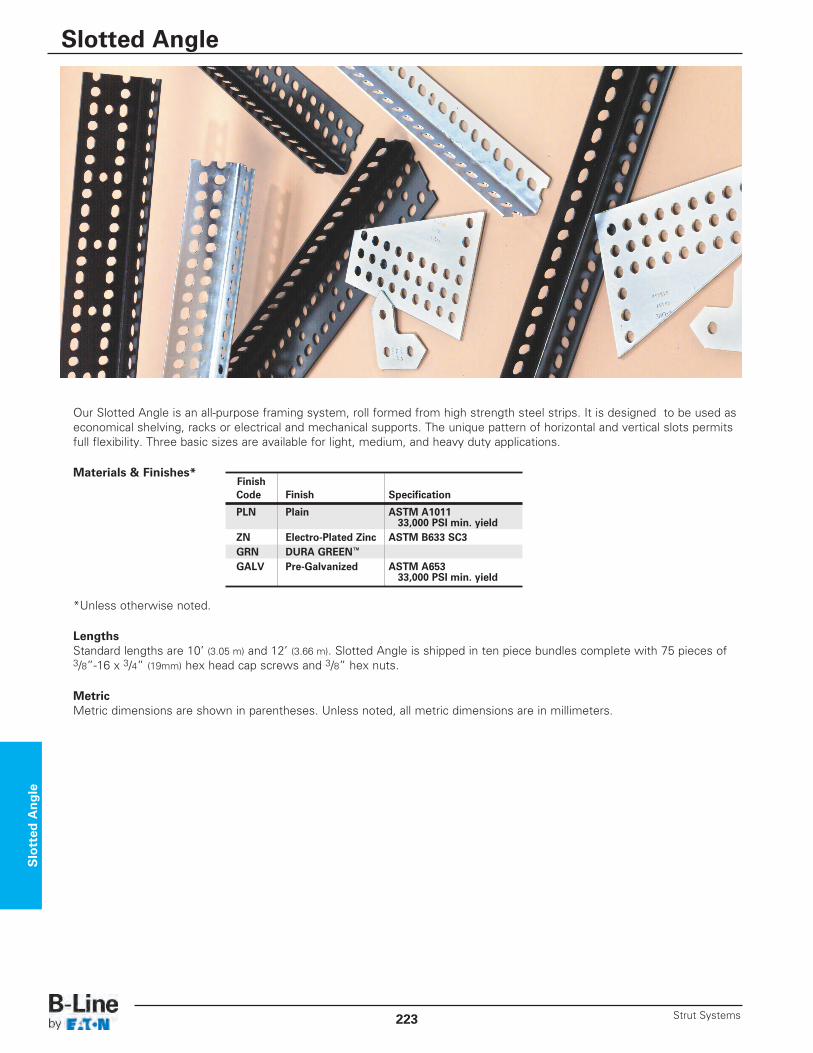
Our Slotted Angle is an all-purpose framing system, roll formed from high strength steel strips. It is designed to be used aseconomical shelving, racks or electrical and mechanical supports. The unique pattern of horizontal and vertical slots permitsfull flexibility. Three basic sizes are available for light, medium, and heavy duty applications.
Materials & Finishes*
*Unless otherwise noted.
Lengths Standard lengths are 10’ (3.05 m) and 12’ (3.66 m). Slotted Angle is shipped in ten piece bundles complete with 75 pieces of3/8”-16 x 3/4” (19mm) hex head cap screws and 3/8” hex nuts.
MetricMetric dimensions are shown in parentheses. Unless noted, all metric dimensions are in millimeters.
FinishCode Finish Specification
PLN Plain ASTM A101133,000 PSI min. yield
ZN Electro-Plated Zinc ASTM B633 SC3GRN DURA GREEN™
GALV Pre-Galvanized ASTM A65333,000 PSI min. yield
Slotted Angle
Slotted Angle
Strut Systems223
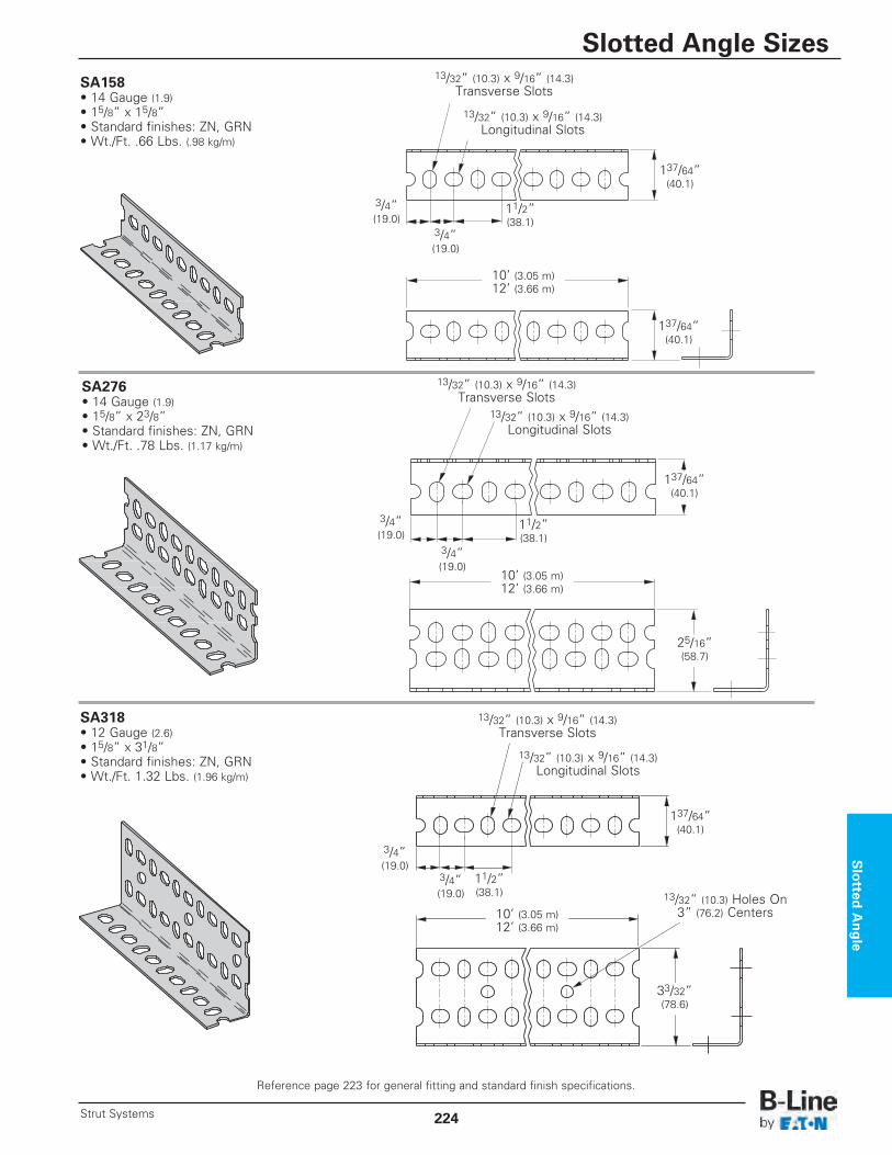
SA158• 14 Gauge (1.9)• 15/8” x 15/8” • Standard finishes: ZN, GRN• Wt./Ft. .66 Lbs. (.98 kg/m)
SA276• 14 Gauge (1.9)• 15/8” x 23/8” • Standard finishes: ZN, GRN• Wt./Ft. .78 Lbs. (1.17 kg/m)
SA318• 12 Gauge (2.6)• 15/8” x 31/8” • Standard finishes: ZN, GRN• Wt./Ft. 1.32 Lbs. (1.96 kg/m)
137/64” (40.1)
11/2” (38.1)
11/2” (38.1)
11/2” (38.1)
10’ (3.05 m)12’ (3.66 m)
13/32” (10.3) x 9/16” (14.3)Transverse Slots
13/32” (10.3) x 9/16” (14.3)Longitudinal Slots
10’ (3.05 m)12’ (3.66 m)
137/64” (40.1)
137/64” (40.1)
137/64” (40.1)
25/16” (58.7)
3/4” (19.0)
3/4” (19.0)
3/4” (19.0)
3/4” (19.0)
3/4” (19.0)
3/4” (19.0)
13/32” (10.3) x 9/16” (14.3)Transverse Slots
13/32” (10.3) x 9/16” (14.3)Longitudinal Slots
13/32” (10.3) x 9/16” (14.3)Transverse Slots
10’ (3.05 m)12’ (3.66 m)
33/32” (78.6)
13/32” (10.3) Holes On 3” (76.2) Centers
13/32” (10.3) x 9/16” (14.3)Longitudinal Slots
Slotted
Angle
Reference page 223 for general fitting and standard finish specifications.
Slotted Angle Sizes
224Strut Systems
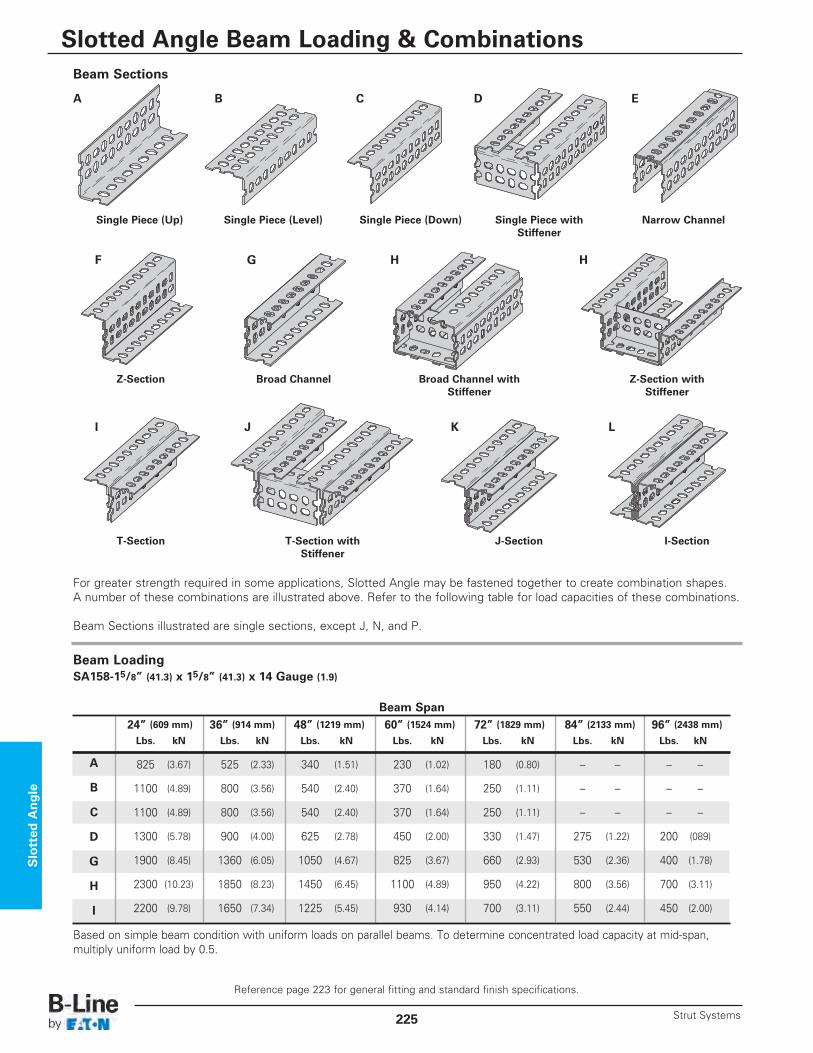
Beam Sections
A
F
Single Piece (Up)
Z-Section
Single Piece (Level)
Broad Channel Broad Channel withStiffener
Z-Section withStiffener
B
Single Piece (Down) Narrow ChannelSingle Piece withStiffener
C D E
G H H
I
T-Section T-Section withStiffener
J-Section I-Section
J K L
Beam Span24” (609 mm) 36” (914 mm) 48” (1219 mm) 60” (1524 mm) 72” (1829 mm) 84” (2133 mm) 96” (2438 mm)
Lbs. kN Lbs. kN Lbs. kN Lbs. kN Lbs. kN Lbs. kN Lbs. kN
825 (3.67) 525 (2.33) 340 (1.51) 230 (1.02) 180 (0.80) – – – –
1100 (4.89) 800 (3.56) 540 (2.40) 370 (1.64) 250 (1.11) – – – –
1100 (4.89) 800 (3.56) 540 (2.40) 370 (1.64) 250 (1.11) – – – –
1300 (5.78) 900 (4.00) 625 (2.78) 450 (2.00) 330 (1.47) 275 (1.22) 200 (089)
1900 (8.45) 1360 (6.05) 1050 (4.67) 825 (3.67) 660 (2.93) 530 (2.36) 400 (1.78)
2300 (10.23) 1850 (8.23) 1450 (6.45) 1100 (4.89) 950 (4.22) 800 (3.56) 700 (3.11)
2200 (9.78) 1650 (7.34) 1225 (5.45) 930 (4.14) 700 (3.11) 550 (2.44) 450 (2.00)
A
B
C
D
G
H
I
Beam LoadingSA158-15/8” (41.3) x 15/8” (41.3) x 14 Gauge (1.9)
Based on simple beam condition with uniform loads on parallel beams. To determine concentrated load capacity at mid-span,multiply uniform load by 0.5.
For greater strength required in some applications, Slotted Angle may be fastened together to create combination shapes.A number of these combinations are illustrated above. Refer to the following table for load capacities of these combinations.
Beam Sections illustrated are single sections, except J, N, and P.
Slotted
Angle
Reference page 223 for general fitting and standard finish specifications.
Slotted Angle Beam Loading & Combinations
Strut Systems225
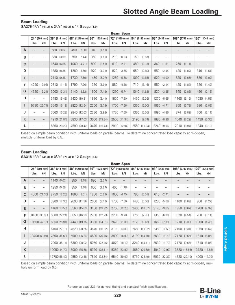
Beam LoadingSA318-15/8” (41.3) x 31/8” (79.4) x 12 Gauge (2.6)
Beam Span24” (609 mm) 36” (914 mm) 48” (1219 mm) 60” (1524 mm) 72” (1829 mm) 84” (2133 mm) 96” (2438 mm) 108” (2743 mm) 120” (3048 mm)
Lbs. kN Lbs. kN Lbs. kN Lbs. kN Lbs. kN Lbs. kN Lbs. kN Lbs. kN Lbs. kN
– – 680 (3.02) 450 (2.00) 340 (1.51) – – – – – – – – – –
– – 830 (3.69) 550 (2.44) 360 (1.60) 210 (0.93) 150 (0.67) – – – – – –
– – 1540 (6.85) 1060 (4.71) 800 (3.56) 610 (2.71) 480 (2.13) 340 (1.51) 250 (1.11) – –
– – 1880 (8.36) 1280 (5.69) 970 (4.31) 820 (3.65) 650 (2.89) 550 (2.44) 420 (1.87) 340 (1.51)
– – 2110 (9.38) 1730 (7.69) 1460 (5.77) 1250 (5.56) 1090 (4.85) 920 (4.09) 820 (3.65) 680 (3.02)
4290 (19.08) 2510 (11.16) 1790 (7.96) 1330 (5.91) 980 (4.36) 710 (3.16) 550 (2.44) 420 (1.87) 320 (1.42)
4320 (19.21) 3000 (13.34) 2140 (9.52) 1600 (7.12) 1290 (5.74) 1040 (4.62) 820 (3.65) 640 (2.85) 490 (2.18)
– – 3480 (15.48) 2430 (10.81) 1890 (8.41) 1620 (7.20) 1430 (6.36) 1270 (5.65) 1160 (5.16) 1030 (4.58)
5780 (25.71) 3640 (16.19) 2820 (12.54) 2200 (9.78) 1700 (7.56) 1350 (6.00) 1060 (4.71) 850 (3.78) 680 (3.02)
– – 3660 (16.28) 2840 (12.63) 2230 (9.92) 1720 (7.65) 1360 (6.05) 1090 (4.85) 874 (3.89) 700 (3.11)
– – 4910 (21.84) 3830 (17.03) 3000 (13.34) 2550 (11.34) 2190 (9.74) 1880 (8.36) 1640 (7.29) 1430 (6.36)
– – 6360 (28.29) 4590 (20.42) 3470 (15.43) 2910 (12.94) 2550 (11.34) 2240 (9.96) 2010 (8.94) 1840 (8.18)
A
B
C
D
E
F
G
H
I
J
K
L
Beam LoadingSA276-15/8” (41.3) x 23/8” (60.3) x 14 Gauge (1.9)
Based on simple beam condition with uniform loads on parallel beams. To determine concentrated load capacity at mid-span,multiply uniform load by 0.5.
Based on simple beam condition with uniform loads on parallel beams. To determine concentrated load capacity at mid-span, mul-tiply uniform load by 0.5.
Slotted
Angle
Reference page 223 for general fitting and standard finish specifications.
Slotted Angle Beam Loading
226Strut Systems
Beam Span24” (609 mm) 36” (914 mm) 48” (1219 mm) 60” (1524 mm) 72” (1829 mm) 84” (2133 mm) 96” (2438 mm) 108” (2743 mm) 120” (3048 mm)
Lbs. kN Lbs. kN Lbs. kN Lbs. kN Lbs. kN Lbs. kN Lbs. kN Lbs. kN Lbs. kN
– – 1140 (5.07) 850 (3.78) 690 (3.07) – – – – – – – – – –
– – 1250 (5.56) 850 (3.78) 600 (2.67) 400 (1.78) – – – – – – – –
4800 (21.35) 2750 (12.23) 1800 (8.01) 1280 (5.69) 1000 (4.45) 790 (3.51) 610 (2.71) – – – –
– – 3900 (17.35) 2690 (11.96) 2050 (9.12) 1700 (7.56) 1480 (6.58) 1280 (5.69) 1100 (4.89) 960 (4.27)
– – 4160 (18.50) 3560 (15.83) 3130 (13.92) 2750 (12.23) 2400 (10.67) 2170 (9.65) 1950 (8.67) 1780 (7.92)
8180 (36.38) 5000 (22.24) 3650 (16.23) 2750 (12.23) 2200 (9.78) 1750 (7.78) 1350 (6.00) 1020 (4.54) 700 (3.11)
10600 (47.15) 6050 (26.91) 4440 (19.75) 3330 (14.81) 2670 (11.88) 2120 (9.43) 1660 (7.38) 1210 (5.38) 1000 (4.45)
– – 6100 (27.13) 4620 (20.55) 3670 (16.32) 3110 (13.83) 2680 (11.92) 2380 (10.59) 2100 (9.34) 1950 (8.67)
13700 (60.94) 7800 (34.69) 5900 (26.24) 4600 (20.46) 3800 (16.90) 3190 (14.19) 2630 (11.70) 2170 (9.65) 1810 (8.05)
– – 7900 (35.14) 6300 (28.02) 5050 (22.46) 4070 (18.10) 3240 (14.41) 2630 (11.70) 2170 (9.65) 1810 (8.05)
– – 10050(44.70) 8000 (35.58) 6320 (28.11) 5350 (23.80) 4650 (20.68) 4040 (17.97) 3520 (15.66) 3120 (13.88)
– – 12700(56.49) 9550 (42.48) 7540 (33.54) 6540 (29.09) 5730 (25.49) 5030 (22.37) 4520 (20.10) 4000 (17.79)
A
B
C
D
E
F
G
H
I
J
K
L
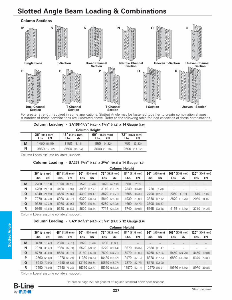
Column Sections
M
Single Piece
Dual ChannelSection
T-Section
T-ChannelSection
T-ChannelSection
N
Broad ChannelSection
Uneven T-Section
I-Section Uneven I-Section
Uneven ChannelSection
Narrow ChannelSection
N N O O
Column Loading - SA158-15/8” (41.3) x 15/8” (41.3) x 14 Gauge (1.9)
Column Loads assume no lateral support.
Column Loads assume no lateral support.
For greater strength required in some applications, Slotted Angle may be fastened together to create combination shapes.A number of these combinations are illustrated above. Refer to the following table for load capacities of these combinations.
P P P Q R
MN
Column Height36” (914 mm) 48” (1219 mm) 60” (1524 mm) 72” (1829 mm)Lbs. kN Lbs. kN Lbs. kN Lbs. kN
1450 (6.45) 1150 (5.11) 950 (4.22) 750 (3.33)
3850 (17.12) 3500 (15.57) 3000 (13.34) 2500 (11.12)
Column Height
36” (914 mm) 48” (1219 mm) 60” (1524 mm) 72” (1829 mm) 84” (2133 mm) 96” (2438 mm) 108” (2743 mm) 120” (3048 mm)
Lbs. kN Lbs. kN Lbs. kN Lbs. kN Lbs. kN Lbs. kN Lbs. kN Lbs. kN
2280 (10.14) 1970 (8.76) 1520 (6.76) 1070 (4.760) 660 (2.93) – – – – – –4760 (21.17) 4490 (19.97) 3995 (17.77) 3140 (13.97) 2340 (10.41) 1750 (7.78) – – – –4940 (21.97) 4680 (20.82) 4310 (19.17) 3870 (17.21) 3665 (16.30) 2700 (12.01) 2060 (9.16) 1610 (7.16)
7270 (32.34) 6920 (30.78) 6370 (28.33) 5840 (25.98) 4930 (21.93) 3850 (17.12) 2870 (12.76) 2060 (9.16)
9520 (42.35) 8970 (39.90) 7990 (35.54) 6280 (27.93) 4660 (20.73) 3500 (15.57) – – – –9865 (43.88) 9330 (41.50) 8620 (38.34) 7715 (34.32) 6740 (29.98) 5365 (23.86) 4115 (18.30) 3210 (14.28)
M
N
O
P
Q
R
Column Loading - SA276-15/8” (41.3) x 23/8” (60.3) x 14 Gauge (1.9)
Column Loads assume no lateral support.
Column Loading - SA318-15/8” (41.3) x 31/8” (79.4) x 12 Gauge (2.6)
Slotted
Angle
Reference page 223 for general fitting and standard finish specifications.
Slotted Angle Beam Loading & Combinations
Strut Systems227
Column Height
36” (914 mm) 48” (1219 mm) 60” (1524 mm) 72” (1829 mm) 84” (2133 mm) 96” (2438 mm) 108” (2743 mm) 120” (3048 mm)
Lbs. kN Lbs. kN Lbs. kN Lbs. kN Lbs. kN Lbs. kN Lbs. kN Lbs. kN
3470 (15.43) 2870 (12.76) 1970 (8.76) 1280 (5.69) – – – – – – – –7970 (35.45) 7360 (32.74) 6570 (29.22) 5270 (23.44) 3670 (16.32) 2580 (11.47) – – – –8770 (39.01) 8580 (38.16) 8180 (36.38) 7690 (34.21) 6970 (31.00) 6260 (27.84) 5460 (24.29) 4460 (19.84)
12560 (55.87) 11970 (53.24) 11360 (50.53) 10480 (46.62) 9470 (42.12) 8370 (37.23) 6880 (30.60) 5370 (23.89)
15940 (70.90) 14750 (65.61) 13160 (58.54) 10560 (46.97) 7370 (32.78) 5170 (23.00) – – – –17550 (78.06) 17150 (76.29) 16360 (72.77) 15360 (68.32) 13970 (62.14) 12570 (55.91) 10970 (48.80) 8960 (39.85)
M
N
O
P
Q
R
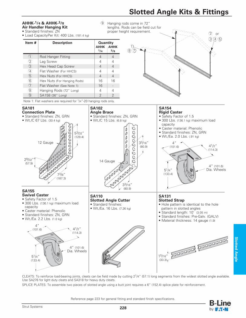
SA101 Connection Plate• Standard finishes: ZN, GRN• Wt./C 67 Lbs. (30.4 kg)
AHHK-1/4 & AHHK-3/8Air Handler Hanging Kit• Standard finishes: ZN• Load CapacityPer Kit: 400 Lbs. (181.4 kg)
SA102 Angle Brace• Standard finishes: ZN, GRN• Wt./C 15 Lbs. (6.8 kg)
SA110 Slotted Angle Cutter• Standard finishes: • Wt./Ea. 16 Lbs. (7.26 kg)
SA131 Slotted Strap• Hole pattern is identical to the hole pattern in slotted angles
• Standard length: 10’ (3.05 m)• Standard finishes: Pre-Galv. (GALV)• Material thickness: 14 gauge (1.9)
73/8” (187.3)
53/32” (129.4)
29/32” (57.9)
12 Gauge
14 Gauge
33/16” (80.9)
33/16” (80.9)
CLEATS: To reinforce load-bearing joints, cleats can be field made by cutting 21/4” (57.1) long segments from the widest slotted angle available.Use SA276 for light duty cleats and SA318 for heavy duty cleats.SPLICE PLATES: To assemble two pieces of slotted angle using a butt joint requires a 6” (152.4) splice plate for reinforcement.
4” (101.6)
51/4” (133.4)
51/4” (133.4)
41/2” (114.3)
4” (101.6)
41/2” (114.3)
4” (101.6)Dia. Wheels
4” (101.6)Dia. Wheels
SA154 Rigid Caster• Safety Factor of 1.5• 300 Lbs. (136.1 kg) maximum load capacity
• Caster material: Phenolic• Standard finishes: ZN, GRN• Wt./Ea. 2.0 Lbs. (.91 kg)
SA155 Swivel Caster• Safety Factor of 1.5• 300 Lbs. (136.1 kg) maximum loadcapacity
• Caster material: Phenolic• Standard finishes: ZN, GRN• Wt./Ea. 2.2 Lbs. (1.0 kg)
15/16” (33.3)
Hanging rods come in 72”lengths. Rods can be field cut forproper height requirement.
Note 1: Flat washers are required for 1/4”-20 hanging rods only.
Item # Description QuantityAHHK AHHK1/4 3/8
1 Rod Hanger Fitting 4 42 Lag Screw 4 43 Hex Head Cap Screw 4 44 Flat Washer (For HHCS) 4 45 Hex Nuts (For HHCS) 4 46 Hex Nuts (For Hanging Rods) 16 167 Flat Washer (See Note 1) 16 -8 Hanging Rods (72” Long) 4 49 SA158 (36” Long) 2 2
16 7
2
3 4 5
8
or
Slotted
Angle
Reference page 223 for general fitting and standard finish specifications.
Slotted Angle Kits & Fittings
228Strut Systems