sls-2 - the upgrade of the swiss light source
TRANSCRIPT
feature articles
J. Synchrotron Rad. (2018). 25, 631–641 https://doi.org/10.1107/S1600577518002722 631
Received 14 December 2017
Accepted 15 February 2018
Edited by M. Eriksson, Lund University, Sweden
Keywords: synchrotron radiation facility;
electron storage ring; low-emittance lattice;
undulator; imaging; molecular biology;
X-ray spectroscopy.
SLS-2 – the upgrade of the Swiss Light Source
Andreas Streun,* Terence Garvey, Lenny Rivkin, Volker Schlott,
Thomas Schmidt, Philip Willmott and Albin Wrulich
Paul Scherrer Institut, 5232 Villigen, Switzerland. *Correspondence e-mail: [email protected]
An upgrade of the Swiss Light Source (SLS) is planned for 2021–2024 and
includes the exchange of the existing storage ring by a new one providing about
40–50 times lower emittance in user operation mode. This will extend the
performance of SLS in particular in the fields of coherent imaging, full-field
tomography, soft X-ray angle-resolved photoelectron spectroscopy and resonant
inelastic X-ray scattering. A science case and a conceptual design for the
machine have been established. As a summary of these reports, the novel lattice
design, undulator developments and scientific highlights are presented.
1. Introduction
An upgrade of the Swiss Light Source (SLS), named SLS-2,
is planned for the period 2021–2024 in order to increase
brightness and the coherent fraction of the synchrotron light
to a level competitive with the newest generation of light
sources. The main component of the upgrade is the exchange
of the existing electron storage ring for a new one providing
40 times lower emittance in user-operation mode.
A conceptual design report (Streun, 2017) as well as a
scientific case (Willmott, 2016) have been established recently.
In this paper we describe the concepts for the new storage-ring
lattice and, for the most critical technical components, outline
the further developments for insertion devices, and present
promising experiments which will be enabled by the upgraded
facility.
2. SLS history and status
The SLS started user operation in June 2001 and has been
operated in top-up mode since then. Today it is fully equipped
with a set of 18 beamlines (11 based on undulators, three on
super-bends and four on normal bends), covering areas as
diverse as atomic and molecular science, catalysis/surface
science, environmental and earth sciences, condensed-matter
physics, life and medical sciences, materials science, and
polymeric and soft-matter research. SLS delivers about 5000 h
of user beam time per year at an availability of 97.6% (12-year
average, 2005–2016), and excels in photon-beam stability
(1 mm r.m.s. at the front-ends) and coupling control (lowest
vertical emittance of 1 pm) (Aiba et al., 2012).
The SLS storage ring is built from 12 triple-bend achromats
(TBAs), connected by long (L), medium (M) and short (S)
straights alternating as L–S–M–S, and thus has a threefold
periodicity. The ring has a circumference of 288 m, and
provides a horizontal emittance of 5 nm at 2.4 GeV. A chicane
for generating 150 fs FWHM X-ray pulses by laser-beam
slicing (at the FEMTO beamline) (Aiba et al., 2013) increases
the emittance to 5.6 nm, and further to �7 nm if operated.
ISSN 1600-5775
The insertion was installed in 2005 and has stopped operation
recently since experiments migrated to SwissFEL, the Swiss
Free-Electron Laser.
Between 2001 and the end of 2016, research output has
produced 5373 peer-reviewed papers, including a uniquely
high fraction of high-profile articles (1334 between an impact
factor of 7.4 and below 25, and 298 with an impact-factor of
25 and higher).
In order to preserve the high scientific output of SLS,
a significant reduction of the emittance is required, which
promises sea-changes in many synchrotron-based scientific
disciplines (Weckert, 2015). It comes at a highly opportune
time, as it will subsume imminent maintenance and replace-
ment of ageing components required at SLS anyway.
3. SLS-2 lattice concept
The upgrade of the storage ring must address the issue of the
comparatively small ring circumference, because, as a rule of
thumb, emittance scales approximately inversely with the third
power of the number of lattice cells (i.e. bending magnets with
adjacent focusing elements) installed along the machine
circumference. In the new generation of multi-bend-achromat
(MBA) lattices, this number was increased through miniatur-
ization of all components. Nonetheless, scaling existing designs
like MAX IV (Leemann et al., 2009), SIRIUS (Liu et al., 2013)
or ESRF-EBS (Farvaque et al., 2013) to the circumference and
energy of the SLS was insufficient to provide the desired
emittance reduction; thus, a novel type of lattice was devel-
oped, which is based on the combination of longitudinal-
gradient bends and reverse-bending magnets.
3.1. Radiation equilibrium
The zero-current horizontal emittance in a storage ring is
determined by the equilibrium between radiation damping
and quantum excitation. The latter depends on the rate of
photon emission, which is given by the strength of the
magnetic field, and on the local dispersion function, because
after emission of a photon an electron starts an oscillation
around the closed orbit corresponding to its reduced energy.
The damping of horizontal oscillations thus excited is given by
the total radiated power, which depends on the magnetic field
strength, and by the horizontal share in the overall damping,
which is affected by transverse gradients in combined-function
bending magnets. These relations are expressed by the
radiation integrals I2;4;5 (Helm et al., 1973): the horizontal
emittance in a flat lattice (i.e. only horizontal bending magnets
and no coupling) is given by the horizontal damping parti-
tioning number,
"x ¼ 1:47� 10�9�E ½GeV�
�2 I5
I2 Jx
; with Jx ¼ 1�I4
I2
; ð1Þ
and E the beam energy.
3.2. Quantum excitation suppression
The quantum excitation integral I5 is given by
I5 ¼Rjhj3H ds; ð2Þ
whereby h is the curvature (inverse radius) of the orbit in the
magnetic field By,
h ¼1
�¼
e
pBy; ð3Þ
and H is the betatron amplitude of the dispersion function �,
H ¼�2 þ �x�þ �x�
0ð Þ2
�x
; ð4Þ
whereby � and � =�� 0=2 are the Courant–Snyder parameters
(Courant & Snyder, 1958) and � and � 0 are the dispersion and
its slope. I5 is minimized by using longitudinal-gradient bends
(LGBs; bending magnets for which the field varies along the
beam path) and by suppressing the dispersion at the LGB
center, where the field is strongest. An optimal function hðsÞ
and optimal initial parameters �o and �xo at the magnet center
can be calculated to obtain the minimal I5 (or the minimal "x),
or a modified optimal function is obtained for given initial
parameters (Streun & Wrulich, 2015). However, in a
conventional periodic cell, quadrupoles are used to focus both
�x and �, which leads to an insufficient focusing of the
dispersion function (or an over-focusing of �x), since the
dispersion production of the bending magnet acts like a
defocusing term, and thus the optimal dispersion �o is out of
reach. But the dispersion and � function can be decoupled by
small reverse bends (RBs), i.e. bending magnets of opposite
polarity and out of phase with the main bending magnet,
which are realized by transverse displacement of the hori-
zontal-focusing quadrupoles in order to obtain the desired
dipolar down-feed (Streun, 2014).
3.3. Radiation damping enhancement
The damping integrals I2 and I4 related to radiated power
and damping partioning are given by
I2 ¼R
h2 ds; I4 ¼R�h 2kþ h2ð Þ ds; ð5Þ
with k = ðe=pÞ @By=@x, the quadrupole moment of a combined
function bend. I2 is enhanced in a lattice using LGBs and RBs,
because the field variation in the LGB increases the radiated
power compared with a homogeneous bending magnet, and
the total absolute bending angle of the lattice is larger than
360�, due to the negative bending of the RBs. Furthermore,
the horizontally focusing quadrupole component (k > 0) in the
RBs (h < 0) redistributes damping in favor of the horizontal
dimension, i.e. I4 becomes negative and Jx is increased.
Altogether, a lattice cell combining LGBs and RBs can
provide up to a five times lower equilibrium emittance
compared with a conventional cell (Streun et al., 2017). This is
an innovative and unique feature of the SLS-2 lattice.
4. SLS-2 lattice
4.1. LGB–RB cell
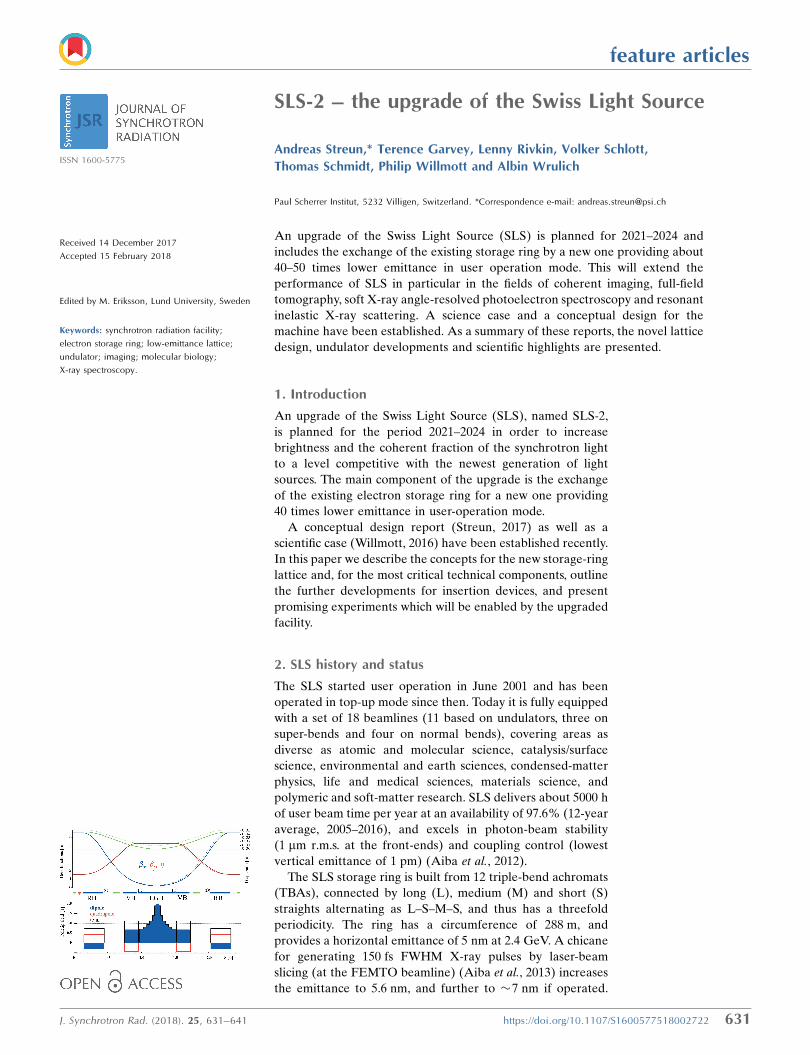
Fig. 1 shows the optical functions and the magnetic fields for
the LGB–RB cell of SLS-2. The cell has a net bending angle of
feature articles
632 Andreas Streun et al. � Upgrade of the Swiss Light Source J. Synchrotron Rad. (2018). 25, 631–641
5�, which is made up from the 6.4� deflection of the center
LGB and the 2 � (�0.7�) deflection of the RBs. The LGB is
realized as a compound magnet made from a pure dipole LGB
of �4.4� sandwiched by two vertically focusing combined-
function bends of 2 � (�1�).
4.2. Lattice layout
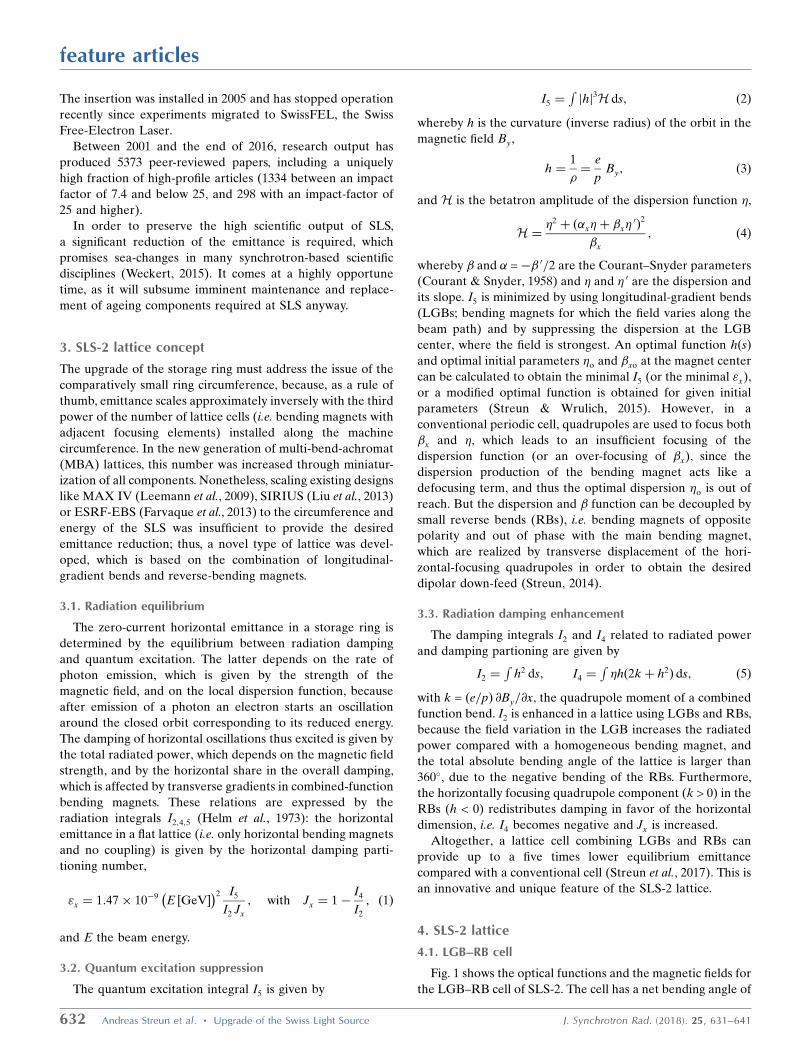
Five full and two half LGB–RB cells form one of the 12
identical seven-bend achromat arcs (7BAs) as shown in Fig. 2,
which replace the existing 12 TBA arcs of three different
types.
Any of the LGBs can be exchanged by a LG-superbend of
up to 6 T peak-field, in order to provide a brilliant source of
X-rays in the 50–100 keV range.
All 12 straight sections are 5.5 m long. Eight full straights
and three half straights are available for undulator installa-
tion, the others being required for injection elements and RF
cavities. The higher lattice symmetry compared with SLS
necessitates modifications of the lattice footprint, mainly
affecting the regions of the present L-straights, while moder-
ately affecting the others.
A comparison of the most important lattice parameters of
SLS and SLS-2 is given in Table 1. For both rings, the beam
energy is 2.4 GeV and the stored current is 400 mA. The
increase of emittance and energy spread in SLS-2 due to intra-
beam scattering is indicated in the table by arrows (!); this
effect only becomes significant for low emittance, and is
negligible for SLS. The SLS lattice is given in its present
configuration, including three 2.9 T superbends and the
chicane for laser-beam slicing (FEMTO), which will not be
part of SLS-2. Three longitudinal gradient super-bends of 6 T
peak-field are included in the SLS-2 lattice.
It is interesting to note that the momentum compaction
factor � of the SLS-2 lattice becomes negative like in a proton
synchrotron below transition energy, because the positive
dependence of time-of-flight on momentum for high relati-
vistic particles in the main bending
magnets is overcompensated by RBs
due to large dispersion and reversed
polarity.
4.3. Acceptance
Optimization of the dynamic accep-
tance is one of the most challenging
problems for low-emittance lattices,
because the strong horizontal focus
in each bending magnet causes large
chromaticity, and the small dispersion of
short lattice cells results in very strong
sextupoles for chromaticity correction.
For the dynamic acceptance optimi-
zation of the SLS-2 storage ring a robust
design strategy was established, which
is based on suppression of first- and
feature articles
J. Synchrotron Rad. (2018). 25, 631–641 Andreas Streun et al. � Upgrade of the Swiss Light Source 633
Figure 2Optical functions and field components for one 7BA arc where the center LGB has beeninterchanged by a super-LGB of 5.5 T peak field. Bending magnets are in dark blue, quadrupoles inred and sextupoles in green.
Table 1Main parameters for the SLS-2 upgrade lattice including three superb-ends in comparison with the existing SLS lattice.
The arrows (!) indicate the increase due to intra-beam scattering at anominal current of 400 mA in 400 of 484 bunches for 10 pm of verticalemittance, and including a third-harmonic RF-system for bunch lengthening.
SLS SLS-2
Circumference (m) 288.0 290.4Horizontal damping partition, Jx 1.00 1.71Momentum compaction, � 6.04 � 10�4
�1.33 � 10�4
Total absolute bending angle 374.7� 561.6�
Lattice tunes, �x , �y 20.4, 8.7 39.2, 15.3Natural chromaticity, �x , �y �67, �21 �95, �35Radiated power (kW) 219.5 221.6Emittance (pm) 5630 98! 126Energy spread (�10�3) 0.86 1.03! 1.07
Figure 1Optical functions and field components for the SLS-2 lattice cellcontaining a center LGB with adjacent vertically focusing bends (VBs),and two RBs. If the RBs were pure quadrupoles, the optical functionswould follow the dashed lines in the upper plot and the emittance wouldbe 4.5 time larger. The field components in the lower plot refer to thepole-tip field at 13 mm bore radius.

second-order sextupole resonance-driving terms by phase
cancellation: in the 7BA arc of SLS-2 this is achieved with cell
tunes of ��x = 3/7 ’ 0.429 and ��y = 1/7 ’ 0.143. The hori-
zontal tune also enables the RBs to provide the most efficient
emittance reduction by dispersion suppression in the LGB
center. Nevertheless, cross-talk between the sextupoles causes
large non-resonant second-order terms, which are amplitude-
dependent tune shifts (ADTS) and second-order chromati-
cities. Suppression requires to back off the ideal cancellation
pattern to some extent, and to fine-tune a total of seven
sextupole and six octupole magnet families (Bengtsson &
Streun, 2017).
The increase of the super-periodicity from three for the
existing lattice with three different straight lengths to 12 in the
SLS-2 lattice with only one type of straight was mainly moti-
vated by dynamic acceptance optimization through elimina-
tion of potentially harmful resonances. Furthermore, identical
arcs support standardization of components and ease of
operation.
By these means, a relative momentum acceptance of about
5% was obtained which provides a Touschek-dominated beam
lifetime of about 9 h (similar to SLS now), and a horizontal
dynamic aperture of about �6 mm at the point of injection,
which enables off-axis injection, accumulation and top-up
from the existing injector.
5. Technical systems
5.1. Injection
The booster synchrotron of the SLS was an innovative
design at its time (Joho et al., 2006). It anticipated features of
modern storage rings, such as small-aperture magnets and
many short lattice cells. Mounted to the inner wall of the
storage-ring tunnel, the booster has a circumference of 270 m,
which is 15/16 of the ring circumference, and delivers rather
low emittances of 10 nm rad horizontal and 2 nm rad vertical
at 2.4 GeV. These low emittances make it very suitable for off-
axis injection into the smaller aperture of the SLS-2 storage
ring. Therefore the SLS-injector will be reused for SLS-2 in its
current form.
For top-up injection, the novel ‘anti-septum’ scheme was
developed. It is based on an orbit bump formed by three
dipole kickers, where a current sheet is placed inside the
middle kicker to compensate the main field at the location
where the injected beam passes (Gough & Aiba, 2017). Since
the pulse of a kicker is weaker and shorter than in a septum
magnet, the anti-septum can be as thin as 1 mm, thus reducing
the distance between stored and injected beam and, with it,
the aperture requirements.
5.2. Magnets
Small apertures are a basic feature of low-emittance MBA
lattices, because they enable an increase of magnet gradients
and thus a reduction of magnet length and miniaturization of
lattice cells. Many small magnets, in turn, result in small peak
dispersion, such that sufficient momentum acceptance is still
provided with small apertures. Due to miniaturization, the
SLS-2 lattice contains 900 magnets in a 290.4 m circumference
(of which 66 m are straights sections), which results in small
inter-magnet distances and high fields and gradients.
The core component is a compound magnet containing the
central LGB with about 2 T peak field, and two vertically
focusing combined-function bending magnets (VBs) in a
common yoke. The RBs are essentially radially shifted quad-
rupoles. Resistive coil and permanent-magnet designs are
being evaluated in parallel for the RB and the LGB compound
magnet, the final decision depending on costs and ongoing
technological progress in the field. Modified versions of these
magnets are used in the dispersion suppressor cells at the ends
of the arcs, i.e. half-LGBs and RBs and VBs with modified
gradients.
Any of the 60 LGBs may be exchanged by a LG-superbend;
it is planned to start with three of these. The design is based on
two pairs of coils, Nb3Sn racetrack-coils to create a narrow
central field peak of 6 T, and NbTi Helmholtz coils to provide
the required field integral (Calzolaio et al., 2017).
Quadruplets of quadrupoles on both ends of the arcs are
used for matching to the straight sections and provide margin
to compensate any focusing from the insertion device.
A total of 288 sextupoles and 144 octupoles are employed
for correction of chromaticity and optimization of acceptance.
120 horizontal and vertical orbit correctors are realized as
additional coils in some of the sextupoles; 24 more in the
straight sections are small dipoles and will be used to steer the
photon beams from the undulators. Small quadrupoles for fine
tuning and gradient corrections, and skew quadrupoles for
coupling control, are realized as additional coils in some of the
octupoles.
5.3. Beam stability
Beam stability will be one of the key operational aspects for
exploiting the improved brightness of SLS-2. For determina-
tion of the electron beam orbit, 144 button-type RF beam-
position monitors (BPMs) will be installed in the storage ring.
The beam positions will be measured with newly designed
BPM electronics, which will provide <50 nm r.m.s. position
noise for fast orbit feedback (FOFB) applications and <1 mm
r.m.s. position resolution for turn-by-turn machine studies. By
using all RF BPMs and all corrector magnets in the storage
ring, a global orbit correction can be applied at a rate of
20 kHz, leading to a FOFB bandwidth of several hundred
hertz when considering all latency contributions of the dedi-
cated FOFB network. The SVD-based global FOFB algorithm
will not only correct for orbit perturbations but will also
provide the possibility of feed-forward corrections and user-
defined adaptations of the reference orbit. The FOFB archi-
tecture will allow the implementation of additional feedback
loops for, for example, betatron tune and beam size by inte-
gration of additional sensors such as photon-BPMs, coupling
or beam size monitors and additional actuators such as normal
and skew quadrupoles. Integration of photon-beam-based
signals requires the development of reliable photon-BPMs,
feature articles
634 Andreas Streun et al. � Upgrade of the Swiss Light Source J. Synchrotron Rad. (2018). 25, 631–641

where a research and development program for SLS-2 is
foreseen to make use of diamond membranes as quadrant
detectors for hard X-rays and gas-based monitors for VUV
and soft X-ray beamlines.
5.4. Radiofrequency
SLS-2 will reuse the existing SLS RF system which consists
of four 500 MHz copper cavities for a maximum sum voltage
of 2.6 MV, and a passive superconducting third-harmonic
(1.5 GHz) twin cavity for bunch lengthening and Landau
damping. Since the momentum compaction of SLS-2 is
negative and smaller than in SLS, the cavities will operate at
the opposite slope of the RF wave for longitudinal focusing
and at a reduced total voltage of 1.4 MV. For the main cavities,
an absorber plug-in is proposed to damp some higher-order
modes.
Due to its age, the RF system would benefit from extensive
refurbishment, like replacement of klystrons by solid state
amplifiers, and new low-level RF and cooling systems. More-
over, operation of the third-harmonic cavity in an active mode
is under consideration to extend the flexibility in suppression
of coupled bunch instabilities at lower current.
5.5. Vacuum system
The vacuum chamber is based on a round beam pipe of
20 mm diameter. Sections with ante-chambers in the LGB
regions, where radiation is emitted at high power, alternate
with sections made from simple round pipes in the RB regions.
The inner surface of the vacuum chamber is coated with non-
evaporable getter (NEG) material, in order to suppress
radiation-induced gas desorption from the chamber walls, and
thus to establish a low average pressure of <10�9 mbar after
only 100 Ah of beam dose. The NEG layer has a thickness of
1 mm in the ante-chambers but 500 nm only in the beam pipe,
in order to reduce the resistive wall impedance.
The onset of turbulent bunch lengthening has been esti-
mated, including impedance contributions from the vacuum
chamber, BPMs, tapers and cavities. The resulting threshold
current of 2 mA without and 3.5 mA with an ideal third-
harmonic RF system for bunch lengthening are well above the
desired beam current of about 1 mA per bunch (400 mA total
current).
5.6. Mechanical engineering
The magnets are mounted on girders, which are supported
by concrete pedestals. The grouping of elements on girders
and the mechanical design of the girders is guided by the
requirements for stiffness and high eigenfrequencies and
by the need for extensive preassembly in order to minimize
the time required to mount the storage ring in the tunnel.
Depending on the elements they carry, the girder supports will
be equipped with manual adjustments or with motorized
movers for remote, even beam-based, alignment. Irrespective
of the final decision on the girder layout and adjustments,
which will also be cost driven, the mechanical tolerance and
stability requirements with regard to beam-dynamics perfor-
mance can be met, and it is the subject of ongoing studies as to
which extent remote-alignment capabilities may shorten the
commissioning period and facilitate operation.
6. Insertion devices
The SLS had been designed to cover a wide photon-energy
spectrum from about 10 eV to 35 keV (excepting superbend
radiation) in order to accommodate both hard and soft X-ray
beamlines. The three types of straights with different lengths
allow long-period electromagnetic undulators, APPLE II type
undulators, and short-period in-vacuum undulators to be
installed. The undulator gaps vary between 20 mm for the 8 m-
long electromagnetic undulator UE212; 11 to 16 mm for the
4 m-long APPLE II undulators with 44 to 56 mm periods; and
4 mm for the 2 m-long in-vacuum undulators with 14 to 19 mm
period length. All soft X-ray undulators provide variable
polarization. The hard X-ray undulators operate at high
harmonics. The standard undulators are operated at room
temperature (RT) and have a 19 mm period, while a 14 mm
period is realized with cryogenic undulators; hence the highest
photon energies can be reached with high-brightness undu-
lator radiation.
The successful concept of the SLS will be adapted to SLS-2.
The reconfiguration of the lattice with only one type of
straight section with a maximum available space for undula-
tors of about 4 m requires a new concept for the electro-
magnetic undulator. All other undulators could basically
remain unchanged. However, in order to exploit the full
potential of SLS-2, the undulators and the beamline optics
have to be matched to the reduced emittance. In the process,
new materials and conceptual designs have to be taken into
account. Fig. 3 shows a possible layout of the straights in SLS-
2, considering also options for canted undulators, or undula-
tors and RF cavities sharing a straight.
In the following sections the options for undulator upgrades
will be presented, grouped in soft X-ray, hard X-ray and the
‘tender’ X-ray regime, which is of growing interest.
feature articles
J. Synchrotron Rad. (2018). 25, 631–641 Andreas Streun et al. � Upgrade of the Swiss Light Source 635
Figure 3Occupancy of straight sections in SLS and in SLS-2.

6.1. Soft X-rays
The SIS (Surface/Interface Spectroscopy; photon-energy
range 10–800 eV) beamline is now served by a quasi-periodic
electromagnetic undulator with variable periods of 212 mm
and 424 mm. For SLS-2, a permanent-magnet undulator
replacement is needed as, otherwise, within the available 4 m,
there would be too few usable periods and hence insufficient
flux. The reason for the long periods was to keep the K-value
and the emitted power reasonably low. The quasi-periodicity
shifts the harmonics to non-integer values so that they are
effectively suppressed by the monochromator.
Harmonics and heat load are less of a problem in circular
polarization mode, because only the fundamental is emitted
on-axis. For linear polarization the ‘Figure-8’ undulator
(Tanaka & Kitamura, 1995) was developed at SPring-8, which
emits only a few harmonics on-axis and the higher harmonics
into off-axis regions. A combined version is the ‘Helical-8’
undulator, proposed to provide all polarization modes with
reduced heat load (Tanaka & Kitamura, 2011). Another
option is the recently developed quasi-periodic ‘Knot-
APPLE’ undulator (Sasaki et al., 2014), which combines
harmonic suppression with efficient reduction of on-axis
power for all polarization modes. A first device has been
realized (Ji et al., 2015). However, quasi-periodic schemes in
APPLE II structures can be optimized only for one polariza-
tion setting and are therefore not optimal.
Alternatively, twin elliptical undulators with opposite heli-
city and a proper phase control can be used to produce linear-
polarized light of any polarization angle (Sasaki, 1997). Since
the circular-polarized light contains no harmonics on-axis, the
linear polarized light emitted on-axis also contains only the
fundamental. This means that heat load at high K-values and
harmonic contamination at low photon energies can be
avoided. At higher photon energies, both undulators are
operated phase-matched with the same helicity, or with
opposite helicity, for fast helicity switching.
In crossed-undulator schemes, the degree of polarization
has to be carefully considered. The degree of polarization
reaches 80% but not over the full central cone. This results in a
flux reduction of a factor of five at 12 eV. However, operation
at high-K, low-photon energies and the small emittance should
be best suited for the SIS beamline. In such a scenario an
online polarization control is mandatory and is available with
the single-shot polarimeter developed at DESY (Babenkov et
al., 2015).
The APPLE-X undulator design for the ATHOS beamline
of SwissFEL can be reused, if the period is increased from
38 mm to about 90–100 mm (a modified version with a 90 mm
period is already under development for the European
XFEL). With a K-value of 10, the photon energy range from
12 to 600 eV can be covered at all linear- and circular-polar-
ization modes. The highest photon energies of the beamline
can be reached on the third harmonic.
The APPLE II type undulators UE56 and UE54 (56 and
54 mm period) presently in use at the SIM (Surface/Interface
Microscopy) and X-treme (X-ray absorption spectroscopy at
high magnetic fields and low temperature) beamlines can be
used further at SLS-2 with only small modification: UE56 is a
twin undulator with an electromagnetic chicane which has to
be replaced with a much shorter permanent-magnet-based
phase-matcher. UE54 is a single undulator, but used with
variable polarization. Switching polarizations takes about 25 s.
A hydraulic system of sub-micrometer precision with new
electronic valves has been successfully tested. It would speed
up polarization changes to a few seconds.
The soft X-ray beamline ADRESS (Advanced Resonance
Spectroscopy) requires a high photon flux due to the required
high resolution. The current undulator, UE44, is a 3.4 m-long
fixed-gap APPLE II undulator with 75 periods of 44 mm, and
an energy range from 180 eV to 2 keV. If an increase of the
lowest photon energy to 400 eV (meaning that the carbon
edge becomes inaccessible) is acceptable, operation of two
units based on the above-mentioned SwissFEL/ATHOS
design at a period of about 33 mm, and reducing the gap size,
would increase the flux by a significant factor of 2.5 with
respect to a continued use of UE44.
However, the ultimate solution for the ADRESS beamline
would be the implementation of the echo-enabled harmonic
generation (EEHG) scheme, proposed originally for use in
FELs (Xiang & Stupakov, 2009), but also considered for use in
storage rings (Evain et al., 2010; Bakr et al., 2011). The EEHG
scheme causes coherent radiation by microbunching of the
electrons at the resonant wavelength, and, although it is trig-
gered by an external laser with a relatively low repetition rate
in the kilohertz range, it could boost the brightness by up to
four orders of magnitude.
6.2. Hard X-rays
The SLS is equipped with four 2 m-long U19 in-vacuum
undulators operated at RT. They provide photons energies
from 5 to 20 keV using the third to 13th harmonics. The
minimum gap is 4.5 mm, which cannot be lowered significantly
in SLS-2 in order to prevent degradation of the elastic scat-
tering beam lifetime and an increase of the corresponding
Bremsstrahlung radiation levels.
The cryogenic undulator U14 (Calvi et al., 2013), with a
magnetic length of 1.7 m, can be operated down to a gap of
4 mm. Below this value radiation losses at the device increase
significantly. SLS has only one vertical scraper in the injection
straight, but two scrapers separated by an appropriate
(i.e. approximately orthogonal) vertical betatron phase
advance would be required to define the vertical acceptance.
Without a second scraper, the undulator with the smallest gap
[precisely, the smallest ðgapÞ2=�y ratio] takes over this role. In
order to enable safe operation at 4 mm gap, a second scraper
will be mandatory for SLS-2.
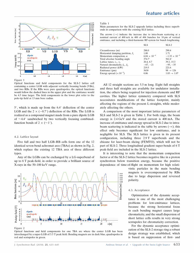
Although the U19 undulator can be further used at SLS-2,
new undulator technology would exploit the smaller emittance
in order to boost the brightness or flux density, in particular
for higher photon energies, as displayed in Fig. 4: the pole
width could be reduced from 42 mm to 25 mm, following the
reduction of the ‘beam stay clear’ aperture in SLS-2 from
feature articles
636 Andreas Streun et al. � Upgrade of the Swiss Light Source J. Synchrotron Rad. (2018). 25, 631–641
about �32 mm to �10 mm. Hence, stronger fields can be
produced without increasing the overall forces on the support
structure. Further, a new magnet material, PrFeB, has become
available, which can be used in cryogenic undulators at liquid-
nitrogen temperatures or even below. It does not show the
phase transition at 135 K of the NdFeB material used in
the existing cryogenic undulator CPMU14, which causes a
precession of the magnetic vector with increasing opening
angle at lower temperatures. Consequently, a simpler cooling
concept could be established.
A possible upgrade scenario considers conversion of the
existing U19 undulators to cryogenic undulators by only
exchanging the magnet arrays and the vacuum components
including the columns between the outer ‘I-beams’ (the
pistons and bellows holding the magnet structures). In this
manner, the excellent mechanics of the support structures
and gap drivers can still be used, which will result in a cost-
efficient upgrade. Only the electronic hardware requires
refurbishment, which is the case for all undulators in SLS after
20 years of operation. The period lengths may be 14 mm or
slightly below, depending on the required photon-energy
range of the specific beamline. The energy gap between the
first and third harmonic requires special attention (also see
Fig. 4): for high photon energies shorter periods would be
more effective, but a period length of about 14 mm is required
to start on the third harmonic at a photon energy of 5 keV.
Superconducting undulators are also becoming a realistic
alternative, whereas in the past the required tolerances on
field and phase errors could not be achieved. Recent devel-
opments based on NbTi and Nb3Sn open possibilities for
short-period undulators with high K-values, which are beyond
the capabilities of permanent-magnet-based designs. Research
and development on a high-field undulator is in progress for
SwissFEL, which, if applied to SLS-2, would extend the energy
spectrum into the 40–60 keV range. Due to the high bright-
ness, this would enable an undulator-based microtomography
beamline which would complement the superbend-based
TOMCAT (TOmographic Microscopy and Coherent rAdi-
ology experimenTs) beamline.
6.3. Tender X-rays
One UE54 APPLE II type undulator sequentially serves
the X-treme (see above) and Phoenix (Photons for the
exploration of nature by imaging and XAS) beamlines.
Phoenix covers the tender X-ray regime using the undulator
up to the 30th harmonic. Obviously the beamline will be more
efficient with an undulator of its own, which can be another
UE54 or a dedicated undulator with a correspondingly shorter
period.
6.4. Bending-magnet beamlines
Presently, eight dipole beamlines are in operation at SLS,
three are based on 2.9 T peak-field, normal-conducting,
superbends, and five on regular dipoles of 1.4 T field.
The superbends will be exchanged by superconducting
LGBs with a maximal peak field of up to 6 T, in order to
extend the maximal photon energy from presently 45 keV to
about 100 keV. The horizontal angle of acceptance for the
beamlines is of the order of a few milliradians. In this range,
the variation of the magnetic field of the super-LGB is still
negligible.
The source points of most of the dipole beamlines are
located in the dipole center; however, two of them have source
points 4� upstream of the center. Since in the 7BA lattice
the LGBs are shorter, these beamlines have to move to the
adjacent upstream bend, which is separated by 5�.
7. Science
This section has been adapted from the science part of the
funding proposal submission to the Swiss National Science
Foundation (SNF) for the SLS-2 upgrade in December 2017.
The future scientific mission of photon science at the SLS-2
will have its foundations firmly based on already established
fields of excellence at PSI. Among others, the SLS to date has
produced world-leading research in activities as varied as
ptychography, native-SAD, full-field tomography, soft-X-ray
ARPES (angle-resolved photoelectron spectroscopy) and
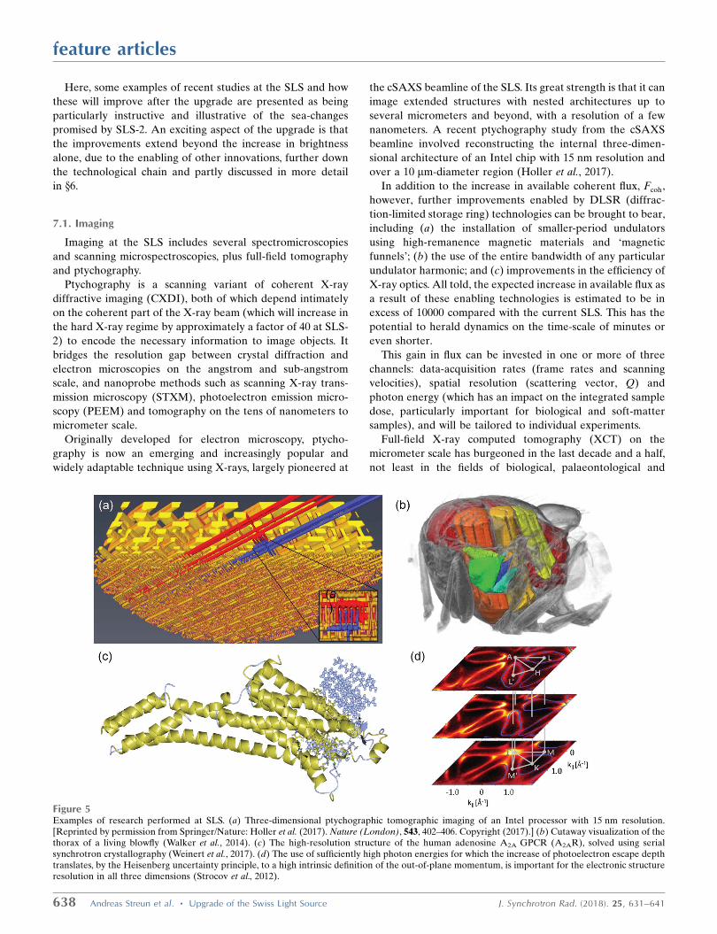
resonant inelastic X-ray scattering (Fig. 5). All of these tech-
niques will profit considerably from the upgrade. Indeed, the
enhanced brightness of SLS-2 will benefit almost all the X-ray
techniques presently practiced at the SLS.
feature articles
J. Synchrotron Rad. (2018). 25, 631–641 Andreas Streun et al. � Upgrade of the Swiss Light Source 637
Figure 4Flux-density (top) and brightness (bottom) for short-period in-vacuumundulators in SLS and SLS-2. Due to the low emittance of SLS-2, theharmonic spectrum will be much cleaner than at SLS.
Here, some examples of recent studies at the SLS and how
these will improve after the upgrade are presented as being
particularly instructive and illustrative of the sea-changes
promised by SLS-2. An exciting aspect of the upgrade is that
the improvements extend beyond the increase in brightness
alone, due to the enabling of other innovations, further down
the technological chain and partly discussed in more detail
in x6.
7.1. Imaging
Imaging at the SLS includes several spectromicroscopies
and scanning microspectroscopies, plus full-field tomography
and ptychography.
Ptychography is a scanning variant of coherent X-ray
diffractive imaging (CXDI), both of which depend intimately
on the coherent part of the X-ray beam (which will increase in
the hard X-ray regime by approximately a factor of 40 at SLS-
2) to encode the necessary information to image objects. It
bridges the resolution gap between crystal diffraction and
electron microscopies on the angstrom and sub-angstrom
scale, and nanoprobe methods such as scanning X-ray trans-
mission microscopy (STXM), photoelectron emission micro-
scopy (PEEM) and tomography on the tens of nanometers to
micrometer scale.
Originally developed for electron microscopy, ptycho-
graphy is now an emerging and increasingly popular and
widely adaptable technique using X-rays, largely pioneered at
the cSAXS beamline of the SLS. Its great strength is that it can
image extended structures with nested architectures up to
several micrometers and beyond, with a resolution of a few
nanometers. A recent ptychography study from the cSAXS
beamline involved reconstructing the internal three-dimen-
sional architecture of an Intel chip with 15 nm resolution and
over a 10 mm-diameter region (Holler et al., 2017).
In addition to the increase in available coherent flux, Fcoh,
however, further improvements enabled by DLSR (diffrac-
tion-limited storage ring) technologies can be brought to bear,
including (a) the installation of smaller-period undulators
using high-remanence magnetic materials and ‘magnetic
funnels’; (b) the use of the entire bandwidth of any particular
undulator harmonic; and (c) improvements in the efficiency of
X-ray optics. All told, the expected increase in available flux as
a result of these enabling technologies is estimated to be in
excess of 10000 compared with the current SLS. This has the
potential to herald dynamics on the time-scale of minutes or
even shorter.
This gain in flux can be invested in one or more of three
channels: data-acquisition rates (frame rates and scanning
velocities), spatial resolution (scattering vector, Q) and
photon energy (which has an impact on the integrated sample
dose, particularly important for biological and soft-matter
samples), and will be tailored to individual experiments.
Full-field X-ray computed tomography (XCT) on the
micrometer scale has burgeoned in the last decade and a half,
not least in the fields of biological, palaeontological and
feature articles
638 Andreas Streun et al. � Upgrade of the Swiss Light Source J. Synchrotron Rad. (2018). 25, 631–641
Figure 5Examples of research performed at SLS. (a) Three-dimensional ptychographic tomographic imaging of an Intel processor with 15 nm resolution.[Reprinted by permission from Springer/Nature: Holler et al. (2017). Nature (London), 543, 402–406. Copyright (2017).] (b) Cutaway visualization of thethorax of a living blowfly (Walker et al., 2014). (c) The high-resolution structure of the human adenosine A2A GPCR (A2AR), solved using serialsynchrotron crystallography (Weinert et al., 2017). (d) The use of sufficiently high photon energies for which the increase of photoelectron escape depthtranslates, by the Heisenberg uncertainty principle, to a high intrinsic definition of the out-of-plane momentum, is important for the electronic structureresolution in all three dimensions (Strocov et al., 2012).

industrial imaging. The TOMCAT beamline at the SLS has
played a leading role in the development of XCT worldwide
since the turn of the century.
The increased brightness from both undulators and high-
field superbends at SLS-2 would allow XCT to be performed
at much higher energies (with the associated penetration
powers and lower integrated doses), and dramatically improve
the dynamic capabilities on the micrometer scale (Walker et
al., 2014), which is expected to access the kilohertz range,
potentially revolutionizing our understanding of countless
life-science, industrial and advanced-manufacturing processes.
Phase-contrast XCT has proved to be especially powerful
for low-dose experiments of weakly absorbing biological
samples in the hard X-ray regime – the transverse coherence
function of SLS-2 will be significantly more isotropic (i.e. the
beam will be rounder). This will facilitate homogeneous edge-
enhancement, and should thereby enable more sophisticated
reconstruction algorithms that go beyond a linear approx-
imation, which presently only makes use of the first-edge
interference fringe. The larger coherent fraction will increase
the phase contrast and thus also the information content that
can be extracted per incident photon, plus it will allow one to
move to higher photon energies for a given coherent fraction
compared with the present. SLS-2 is therefore expected to
strongly benefit phase-contrast imaging in all the variants
offered at the SLS, including Talbot interferometry and
Zernike techniques.
7.2. Molecular biology
Third-generation synchrotrons have revolutionized modern
macromolecular crystallography (MX). To date, well over
120000 atomic resolution biological structures have been
deposited in the Protein Data Bank (http://www.pdb.org).
However, one important class of protein, membrane proteins,
including their subclass, G-protein-coupled receptors
(GPCRs), which accounts for one-third of all proteins and
two-thirds of medicinal drug targets, is extremely under-
represented (1 to 2%). This is in a large part due to their
hydrophobic nature, which makes crystallization difficult and
normally limits crystal sizes to the micrometer scale. Such
crystals require micrometer- or submicrometer beam focusing,
which, until the advent of DLSRs, meant divergences in the
horizontal plane that weakened the diffraction signal at high
resolution. MX at SLS-2 will therefore concentrate on such
systems, individually tailoring case-for-case the division of the
improved emittance between divergence and focus size.
Due to the onset of radiation damage, individual micro-
crystals are insufficient for a complete data set, hence
diffraction data from multiple crystals are merged (Smith et
al., 2012). Prompted by successes in serial femtosecond crys-
tallography (SFX) at XFELs, there has been a thrust in the last
five years towards similar approaches using synchrotron
radiation in a technique coined synchrotron serial crystal-
lography (SSX) (Diederichs & Wang, 2017). SSX can be
carried out at room and cryogenic temperatures alike,
requiring novel approaches to sample preparation, delivery,
data collection and processing.
Despite the one to two orders of magnitude reduction in
the highest tolerable dose compared with cryo-MX, RT-SSX
offers several advantages, including sampling conformational
landscapes, dispensing with cryoprotectants and, crucially, the
possibility of investigating dynamic processes down to the
microsecond time-scales (Panneels et al., 2015). Moreover, and
importantly with regard to the tight but quasi-parallel focusing
attainable at SLS-2, it has been demonstrated that, in contrast
to cryo-MX, there is a positive correlation between dose rate
and maximum tolerable integrated dose in RT-SSX, which
enables the measurement of more useful diffraction data by
approximately a factor of six when increasing the dose rates
from 0.5 to 5 MGy s�1 (Owen et al., 2014).
With some notable but rare exceptions, the large majority of
membrane proteins typically only produce weakly diffracting
crystals with dimensions of the order of a few micrometers or
still smaller. For these studies, the high brightness and small,
parallel, beam of SLS-2 will be crucial in enhancing signal-to-
noise ratios and reducing sample consumption. Since many
membrane proteins are expected to be novel, experimental
phasing is required to reveal their structures. Recent progress
in native-SAD phasing has led to great advances in de novo
phase determination (Liu & Hendrickson, 2015). SLS-2 will
provide a timely opportunity to optimize existing MX beam-
lines for native-SAD experiments, which require X-rays down
to 3 keV and sample environments with minimum background
scattering and absorption (Wagner et al., 2016).
The superior signal-to-noise ratio and the higher
throughput of SSX that will be achieved with SLS-2 will be the
key to unlocking the full potential of time-resolved studies.
SSX, in combination with complementary XFEL studies, such
as those possible at the sister facility SwissFEL, will thus
continue to be the only reasonable techniques for protein
dynamics on the millisecond to femtosecond timescale.
7.3. X-ray spectroscopies
The majority of X-ray spectroscopies will profit from the
smaller focal spots possible at SLS-2. At a typical undulator
beamline, the horizontal source size will be approximately a
factor of six smaller than at present. As the divergence is also
approximately eight times smaller, the beam footprint in the
x-direction will be correspondingly smaller, allowing any
focusing optics to be positioned significantly further down-
stream, enabling more extreme demagnification and a more
efficient use of circular diffraction-based optics such as Fresnel
zone plates. This will allow soft-X-ray ARPES with nano-
focusing, enabling operando- and domain-formation studies of
emerging electronic materials (Strocov et al., 2014).
Resonant X-ray inelastic scattering (RIXS) is a rapidly
developing experimental method in which photons resonant
with electronic transitions are inelastically scattered from
matter (Ament et al., 2011). The energy difference between
the scattered and incident photon can range between meV and
a few eV. This energy loss, plus the momentum transfer and
feature articles
J. Synchrotron Rad. (2018). 25, 631–641 Andreas Streun et al. � Upgrade of the Swiss Light Source 639
change in polarization between the incoming and outgoing
photon, can be directly associated with important processes
related to emerging electronic and superconducting materials
such as phonon-, magnon- or low-energy electron–hole-pair
excitations.
The energy resolution of a RIXS experiment is determined
by the spot size on the sample in the dispersive direction of an
analysis grating spectrometer. The tighter focal spot-size of
SLS-2 improves the resolution in principle by this amount.
This will be further enhanced at SLS-2 by extending the
beamline by over a factor of two to approximately 100 m, and
increasing the demagnification of the incident spot size. In this
manner, sub-10 meV resolution should be obtained, with the
option of domain raster-scanning with submicrometer-sized
beams on the sample and enabling the possibility of following,
among other things, operando magnetic or ferroelectric
domain switching.
Another interesting development is to disperse the incident
radiation from the grating monochromator and image this
onto the sample. Perpendicular to the dispersed incident
beam, the focus remains tight, thereby preserving the resolu-
tion. By dispersing the scattered radiation with a second
grating, the image formed on an area detector allows the
parallel detection of both the incident- and inelastically scat-
tered spectra in orthogonal directions (Strocov, 2010),
enabling efficient, high-resolution, time-resolved experiments.
Hard X-ray scanning spectroscopies will also profit from the
tight focuses possible at SLS-2. Moreover, line tomographies
(which involve two transverse scanning coordinates and one
rotational coordinate) will, like MX, take advantage of both
tight and parallel beams (Corkhill et al., 2017) down to the
sub-micrometer scale. These ‘chemical imaging’ techniques
exploit one or more of several signals (e.g. fluorescence,
XANES, XRD) simultaneously, and can be applied to disci-
plines as broad as art history, cultural heritage, heterogeneous
catalysis, battery technologies and environmental sciences.
8. Conclusion and outlook
Most third-generation synchrotron facilities are either
considering or actively undergoing an upgrade. It is imperative
that the SLS does likewise. Novel machine elements pioneered
at the PSI, in particular reverse bends and longitudinal
gradient bends, enable an approximately factor of 50
improvement in horizontal emittance (zero current emit-
tance), despite the small ring circumference. This will maintain
the SLS as one of the best-performing synchrotron facilities
worldwide for the foreseeable future.
The beamline upgrades will be in two phases. The first
phase, in parallel with the machine upgrade, will encompass
those beamlines most positively impacted by the increased
brightness, probably including ptychography, full-field tomo-
graphy, macromolecular crystallography and resonant
inelastic X-ray scattering.
The SLS proposed upgrade Conceptual Design Report is
being reviewed by the Swiss authorities to be included in
the next ‘Swiss Research Infrastructures Roadmap’. Present
planning foresees the realization of the project in the period
2021–2024.
A full technical design of all machine sub-systems will be
completed over the next two years. Prototypes of critical
components will be built and tested, and calls for tenders for
large series components (magnets, vacuum chambers, girders
etc.) will be prepared in 2020. Procurement, assembly and test
of components are foreseen in the period 2021 to 2022. As
there is a strong desire to minimize the down-time of the SLS,
we plan to remove the present storage ring, replace it with the
new ring and commission both the accelerator and beamlines
in a period not exceeding 18 months (second quarter of 2023
to third quarter of 2024). Thus the SLS should be ready again
for users before the end of 2024.
Acknowledgements
Many colleagues at PSI have contributed to the Science Case,
to the Conceptual Design Report and/or to the funding
proposal, and thus indirectly to this paper. In alphabetical
order: Gabriel Aeppli, Masamitsu Aiba, Alexander Anghel,
Uwe Barth, Johan Bengtsson, Michael Boge, Oliver Bunk,
Ciro Calzolaio, Marco Calvi, Alessandro Citterio. Micha
Dehler, Karsten Dreyer, Christopher Gough, Dominique
Hauenstein, Juri Honegger, Boris Keil, Philippe Lerch,
Stephan Maag, Andreas Menzel, Marco Negrazus, Frithjof
Nolting, Beat Ronner, Stephane Sanfilippo, Corina Sattler,
Thorsten Schmitt, Lothar Schulz, Marco Stampanoni, Lukas
Stingelin, Vladimir Strokov, Vjeran Vrankovic, Meitian Wang,
Johan Wickstrom, Elmar Zehnder and Elke Zimoch. Further,
we would cordially like to thank our CDR review committee
for thorough evaluation of the Conceptual Design Report and
valuable recommendations: Carlo Bocchetta, Joel Chavanne,
Mikael Eriksson, In Soo Ko and Richard Walker.
References
Aiba, M., Beaud, P., Boge, M., Ingold, G., Keil, B., Ludeke, A., Milas,N., Rivkin, L., Saa Hernandez, A., Schilcher, T., Schlott, V. &Streun, A. (2013). Synchrotron Radiat. News, 26.3, 4–8.
Aiba, M., Boge, M., Milas, N. & Streun, A. (2012). Nucl. Instrum.Methods Phys. Res. A, 694, 133–139.
Ament, L. J. P., van Veenendaal, M., Devereaux, T. P., Hill, J. P. &van den Brink, J. (2011). Rev. Mod. Phys. 83, 705–767.
Babenkov, S. V., Aristov, V. Y., Molodtsova, O. V., Winkler, K.,Glaser, L., Shevchuk, I., Scholz, F., Seltmann, J. & Viefhaus, J.(2015). Nucl. Instrum. Methods Phys. Res. A, 777, 189–193.
Bakr, M., Huck, H., Honer, M., Khan, S., Molo, R., Nowaczyk, A.,Schick, A., Ungelenk, P. & Zeinalzadeh, M. (2011). Proceedingsof the Second International Particle Accelerator Conference(IPAC’11), San Sebastian, Spain, 4–9 September, 2011, pp. 3076–3078.
Bengtsson, J. & Streun, A. (2017). Robust Design Strategy for SLS-2.Technical Report SLS2-BJ84-001. Paul Scherrer Institut, Villigen,Switzerland.
Calvi, M., Schmidt, T., Anghel, A., Cervellino, A., Leake, S. J.,Willmott, P. R. & Tanaka, T. (2013). J. Phys. Conf. Ser. 425, 032017.
Calzolaio, C., Sanfilippo, S., Sidorov, S., Anghel, A. & Streun, A.(2017). IEEE Trans. Appl. Supercon. 27, 4000305.
Corkhill, C., Crean, D., Bailey, D., Makepeace, C., Stennett, M.,Tappero, R., Grolimund, D. & Hyatt, N. (2017). Nat. Mater. Degrad.1, 19.
feature articles
640 Andreas Streun et al. � Upgrade of the Swiss Light Source J. Synchrotron Rad. (2018). 25, 631–641

Courant, E. & Snyder, H. (1958). Ann. Phys. 3, 1–48.Diederichs, K. & Wang, M. (2017). Methods Mol. Biol. 1607, 239–
272.Evain, C., Couprie, M.-E., Filhol, J.-M., Labat, M., Nadji, A. &
Zholents, A. (2010). Proceedings of the First International ParticleAccelerator Conference (IPAC’10), Kyoto, Japan, 23–28 May 2010,pp. 2308–2310.
Farvaque, L., Carmigiani, N., Franchi, A., Le Bec, G., Liuzzo, S., Nash,B., Perron, T. & Raimondi, P. (2013). Proceedings of IPAC’2013,Shanghai, People’s Republic of China, pp. 79–81.
Gough, C. H. & Aiba, M. (2017). Proceedings of the 8th InternationalParticle Accelerator Conference (IPAC’17), Copenhagen,Denmark, 14–19 May 2017, pp. 774–776.
Helm, R. H., Lee, M. J., Morton, P. L. & Sands, M. (1973). IEEETrans. Nucl. Sci. 20, 900–901.
Holler, M., Guizar-Sicairos, M., Tsai, E. H. R., Dinapoli, R., Muller,E., Bunk, O., Raabe, J. & Aeppli, G. (2017). Nature (London), 543,402–406.
Ji, F., Chang, R., Zhou, Q., Zhang, W., Ye, M., Sasaki, S. & Qiao, S.(2015). J. Synchrotron Rad. 22, 901–907.
Joho, W., Munoz, M. & Streun, A. (2006). Nucl. Instrum. MethodsPhys. Res. A, 562, 1–11.
Leemann, S., Andersson, A., Eriksson, M., Lindgren, L.-J., Wallen, E.,Bengtsson, J. & Streun, A. (2009). Phys. Rev. ST Accel. Beams, 12,120701.
Liu, L., Milas, N., Mukai, A. H. C., Resende, X. R., Rodrigues,A. R. D. & Sa, F. H. (2013). Proceedings of IPAC’2013, Shanghai,People’s Republic of China, pp. 1874–1876.
Liu, Q. & Hendrickson, W. A. (2015). Curr. Opin. Struct. Biol. 34,99–107.
Owen, R. L., Paterson, N., Axford, D., Aishima, J., Schulze-Briese, C.,Ren, J., Fry, E. E., Stuart, D. I. & Evans, G. (2014). Acta Cryst. D70,1248–1256.
Panneels, V., Wu, W., Tsai, C. J., Nogly, P., Rheinberger, J., Jaeger, K.,Cicchetti, G., Gati, C., Kick, L. M., Sala, L., Capitani, G., Milne, C.,Padeste, C., Pedrini, B., Li, X. D., Standfuss, J., Abela, R. &Schertler, G. (2015). Struct. Dyn. 2, 041718.
Sasaki, S. (1997). Proceedings of the 1997 Particle AcceleratorConference (PAC 97), Vancouver, Canada, pp. 802–804.
Sasaki, S., Miyamoto, A., Kawata, N., Mitsuyasu, T. & Qiao, S. (2014).Proceedings of the 5th International Particle Accelerator Conference(IPAC-2014), 15–20 June 2014, Dresden, Germany, pp. 2026–2028.
Smith, J. L., Fischetti, R. F. & Yamamoto, M. (2012). Curr. Opin.Struct. Biol. 22, 602–612.
Streun, A. (2014). Nucl. Instrum. Methods Phys. Res. A, 737, 148–154.Streun, A. (2017). Editor. SLS-2 Conceptual Design Report. Paul
Scherrer Institut, Villigen, Switzerland.Streun, A., Aiba, M., Boge, M., Ehrlichman, M., Hernandez, A. S. &
Xu, H. (2017). ICFA Beam Dynam. Newsl. 71, 213–223.Streun, A. & Wrulich, A. (2015). Nucl. Instrum. Methods Phys. Res.
A, 770, 98–112.Strocov, V. N. (2010). J. Synchrotron Rad. 17, 103–106.Strocov, V. N., Kobayashi, M., Wang, X., Lev, L. L., Krempasky, J.,
Rogalev, V. V., Schmitt, T., Cancellieri, C. & Reinle-Schmitt, M. L.(2014). Synchrotron Radiat. News, 27, 31.
Strocov, V. N., Shi, M., Kobayashi, M., Monney, C., Wang, X.,Krempasky, J., Schmitt, T., Patthey, L., Berger, H. & Blaha, P.(2012). Phys. Rev. Lett. 109, 086401.
Tanaka, T. & Kitamura, H. (1995). Nucl. Instrum. Methods Phys. Res.A, 364, 368–373.
Tanaka, T. & Kitamura, H. (2011). Nucl. Instrum. Methods Phys. Res.A, 659, 537–542.
Wagner, A., Duman, R., Henderson, K. & Mykhaylyk, V. (2016).Acta Cryst. D72, 430–439.
Walker, S. M., Schwyn, D. A., Mokso, R., Wicklein, M., Muller, T.,Doube, M., Stampanoni, M., Krapp, H. G. & Taylor, G. K. (2014).PLoS Biol. 12, e1001823.
Weckert, E. (2015). IUCrJ, 2, 230–245.Weinert, T., Olieric, N., Cheng, R., Brunle, S., James, D., Ozerov, D.,
Gashi, D., Vera, L., Marsh, M., Jaeger, K., Dworkowski, F.,Panepucci, E., Basu, S., Skopintsev, P., Dore, A. S., Geng, T., Cooke,R. M., Liang, M., Prota, A. E., Panneels, V., Nogly, P., Ermler, U.,Schertler, G., Hennig, M., Steinmetz, M. O., Wang, M. & Standfuss,J. (2017). Nat. Commun. 8, 542.
Willmott, P. R. (2016). SLS-2: Science Case. Paul Scherrer Institut,Villigen, Switzerland.
Xiang, D. & Stupakov, G. (2009). Phys. Rev. ST Accel. Beams, 12,030702.
feature articles
J. Synchrotron Rad. (2018). 25, 631–641 Andreas Streun et al. � Upgrade of the Swiss Light Source 641