sm-cyclo 4ooo series - rmg industrial adjunts/sumitomo/cyclo 4000.pdf4ooo series sm-cyclo ......
TRANSCRIPT

4OO
O S
ERIE
S
SM-CYCLO®
Speed Reducers and Gearmotors
THEAVAILABLESOLUTION,
WORLDWIDE.
Catalog
04.401.50.009

A UNIQUE CONCEPT IN SPEED REDUCERS & GEARMOTORS
SM-CYCLO cycloidal reducers and gearmotors are able to withstand shock loads to 500% of their ratings, and we warrantthem for two full years.
Because of their unique advantages, exceptionalperformance and reliability, SM-CYCLO®
Reducers and SM-CYCLO® Gearmotors are in use in a wide variety of industries worldwide. SM-CYCLO® Reducers and SM-CYCLO®
Gearmotors have gained special recognition where severe working conditions prevail and where equipment breakdowns cannot be tolerated.
For over 25 years we have provided a nationwidesales, engineering, and service organization. Ournational network of local representatives anddistributors offers you comprehensive, fast andefficient service.
Sumitomo Machinery Corporation of America, a world leader in power transmission, hasproduced well over 6 million SM-CYCLO® DriveSpeed Reducers and SM-CYCLO® Gearmotors.
Slow speed shaft
Casing
Ring gear housing
Ring gear roller
Ring gear pin
Slow speed shaft rollerSlow speed shaft pin
Eccentric cam androller assemblyHigh speed end shield
High speed shaft
Cycloid disc(2 disc system)
Motor flange bracket
Eccentric cam androller assembly
Slow speed shaft pin
Slow speed shaft
Casing
Ring gear housing
Cycloid disc (2 disc system)
Ring gear pin
Ring gear roller

TABLE OF CONTENTS
Nomenclature . . . . . . . . . . . . . . . . . . . . . . . . . . . . . . . . 66How To Select Frame Size and Model . . . . . . . . . . . . . 67Gearmotor Classification Table . . . . . . . . . . . . . . . . . . . 67AGMA Load Classification Table . . . . . . . . . . . . . . . 68, 69Rating Tables . . . . . . . . . . . . . . . . . . . . . . . . . . . . . 70-107Dimensions
HM Single Reduction . . . . . . . . . . . . . . . . . 108, 109HM Double Reduction . . . . . . . . . . . . . . . . . 110, 111VM Single Reduction . . . . . . . . . . . . . . . . . 112, 113VM Double Reduction . . . . . . . . . . . . . . . . . 114, 115HFM Single Reduction . . . . . . . . . . . . . . . . 116, 117VFM Double Reduction . . . . . . . . . . . . . . . . 118, 119
Single Phase Electric MotorsCharacteristics . . . . . . . . . . . . . . . . . . . . . . . . . . 120Standard Wiring Diagram . . . . . . . . . . . . . . . . . . 120Motor Construction . . . . . . . . . . . . . . . . . . . . . . . 120Nomenclature . . . . . . . . . . . . . . . . . . . . . . . . . . . 121Selection Table . . . . . . . . . . . . . . . . . . . . . . . . . . 121Dimensions
HM Single Reduction . . . . . . . . . . . . . . . . . 122VM Single Reduction . . . . . . . . . . . . . . . . .123
SM-CYCLO REDUCER/GEARMOTORCOMMON DIMENSIONS AND SPECIFICATIONSAllowable Overhung Load - Slow Speed Shaft . . 124, 125Allowable Overhung Load - High Speed Shaft . . . . . . 126Shaft Tolerances and Tapped Hole Dimensions . . . . . 127Slide Rails . . . . . . . . . . . . . . . . . . . . . . . . . . . . . . . . . . 128
WATER TREATMENT/MIXER OPTIONSTorque Limiter
Features . . . . . . . . . . . . . . . . . . . . . . . . . . . . . . . 131Principle and Structure . . . . . . . . . . . . . . . . . . . . 132Extended Use of Torque Limiter . . . . . . . . . 132, 133How To Readjust Preset Torque . . . . . . . . . . . . 134Selection Tables . . . . . . . . . . . . . . . . . . . . . 135-139Dimensions . . . . . . . . . . . . . . . . . . . . . . . . . 140, 141
Clarifier Drive (Triple Reduction)Selection Table . . . . . . . . . . . . . . . . . . . . . . 142, 143Dimensions . . . . . . . . . . . . . . . . . . . . . . . . . 144, 145Lubrication . . . . . . . . . . . . . . . . . . . . . . . . . 146, 147
14V and 17V Extended BasesFeatures and Benefits . . . . . . . . . . . . . . . . . . . . . 148Bending Moments and Thrust Capacities . . . . . . 149Typical Arrangement and Assembly . . . . . . . . . . 150Base Dimensions . . . . . . . . . . . . . . . . . . . . . . . . 151
Operating Principles . . . . . . . . . . . . . . . . . . . . . . . . . . 152
GENERALFeatures and Benefits . . . . . . . . . . . . . . . . . . 2, 3How It Works . . . . . . . . . . . . . . . . . . . . . . . . . . . 3Basic Information and Recommendations . . . 4, 5Nomenclature and Mounting Positions . . . . . . 6-8
SM-CYCLO REDUCERSHow To Select . . . . . . . . . . . . . . . . . . . . . . . . . 10AGMA Load Classifications . . . . . . . . . . . . . . . 11Rating Tables . . . . . . . . . . . . . . . . . . . . . . . 12-27Standard Ratio Combinations . . . . . . . . . . . . . 28Dimensions
Single Reduction - Foot Mount“C” Face Adaptor . . . . . . . . . . . . 29-31H and HJ (HC) . . . . . . . . . . . . . . . . . 32HP . . . . . . . . . . . . . . . . . . . . . . . . . . 33H-SB . . . . . . . . . . . . . . . . . . . . . 34, 35H-HX (HS) . . . . . . . . . . . . . . . . . . . . 36HF and HFJ (HFC) . . . . . . . . . . . . . 37
Double Reduction - Foot MountH and HJ (HC) . . . . . . . . . . . . . . 38, 39H-SB . . . . . . . . . . . . . . . . . . . . . 40, 41H-HX (HS) . . . . . . . . . . . . . . . . . . . . 42HF and HFJ (HFC) . . . . . . . . . . . . . 43
Single Reduction - Flange MountV and VJ (VC) . . . . . . . . . . . . . . . . . 44VP . . . . . . . . . . . . . . . . . . . . . . . . . . 45V-SB . . . . . . . . . . . . . . . . . . . . . 46, 47V-HX (HS) . . . . . . . . . . . . . . . . . . . . 48VF and VFC . . . . . . . . . . . . . . . . . . 49
Double Reduction - Flange MountV and VJ (VC) . . . . . . . . . . . . . . . . . 50V-HS . . . . . . . . . . . . . . . . . . . . . . . . 51V-VX (SB) . . . . . . . . . . . . . . . . . 52, 53VF and VFJ (VFC) . . . . . . . . . . . . . . 54
SM-CYCLOGEARMOTORS AND BRAKEMOTORS“F” Frame Motors and Features . . . . . . . . . . . . 56Electric Motors and Brakemotors . . . . . . . . . . . 57How It Works . . . . . . . . . . . . . . . . . . . . . . . . . . 57Standard Motor Characteristics . . . . . . . . . 58, 59Assembly of Standard Motors . . . . . . . . . . . . . 60Rectifier Data . . . . . . . . . . . . . . . . . . . . . . . . . . 61Brakemotor Characteristics . . . . . . . . . . . . 62, 63Assembly of Brakemotors . . . . . . . . . . . . . 64, 65
NOTE: Previous nomenclature is shown in (parentheses).

FEATURES AND BENEFITS
2
Highest Overload Capacity — 500% plusThe SM-CYCLO® speed reducer has
the strength to withstand overloads thatbreak the teeth of other reducers.Here’s why:
At least 2/3 of SM-CYCLO® speedreducer’s teeth share the shock ofoverload, and each tooth is cycloidallyshaped — it can’t be sheared off.
Compare that to conventionalreducers, where one or two teethabsorb the entire shock — teeth whichhave a defined shear point and canbreak off.
Exceptional Life — 24 month warrantyTest SM-CYCLO® speed reducers
show negligible wear after 50,000 hourlife tests, and indications are futurewear would be negligible. No oneknows how long an SM-CYCLO®
speed reducer, used correctly, will last.Virtually no wear failures haveoccurred in the over five milliondrives put into operation since 1939.
This remarkable record is due toSM-CYCLO® speed reducer’s uniquerolling action and the use of 52100high-carbon chromium bearing steels,through-hardened and tempered toRockwell C57-63 in all major torque-transmitting parts.
High Efficiency Even at High RatiosTorque transmitting parts roll, do not
grind. There is no sliding friction, sooutput torque/input horsepower ratioapproaches 95% efficiency in singlereduction units.Capacity for Frequent Stop-Start andSevere Reversing
Flywheel (WR2) effect in theSM-CYCLO® speed reducer is reduced toa minimum, so that it responds quickly inthese applications. The shear-freecycloidal teeth also make the unit idealfor those applications which quickly wearout competitive reducers.
CompactnessSM-CYCLO® speed reducers are
considerably smaller than conventionalreducers, but they don’t sacrificeefficiency in the higher ratios as othercompacts must. This means you can use not only a smaller reducer, but asmaller motor too, because the highefficiency lets you obtain the sameoutput torque you previously derivedfrom a larger motor.
No Thermal Factor LimitationsSM-CYCLO® speed reducer’s
smooth, almost frictionless operation allbut eliminates the conventionallimitations due to heat. In all sizes, thedrive has a thermal rating that exceedsmechanical capacities.
SM-CYCLO® SPEED REDUCERmany teeth share the shock of overload allowingup to 500% SHOCK LOAD CAPACITY
CONVENTIONAL HELICAL GEAR:1 or 2 teeth absorb the entire shock ofoverload.
SM-CYCLO® SPEED REDUCERAll torque transmitting parts roll, don’t grind.
CONVENTIONALHELICAL REDUCERTorque transmitting partsgrind, wear, and can break off.
A SMALLER SIZE REDUCER (Up to 60% smaller)
PLUS A SMALLER MOTOR
MEANS YOU GET A MORE COMPACTAND EFFICIENT PRODUCT

3
Smooth, Silent OperationAll parts of the speed reducer are
completely symmetrized around theshafts, and the two cycloid discs whichtransmit the power are balanced in180° opposition, for perfectly balancedcentrifugal force. The result is smooth,vibrationless and quiet operation.
Wide Range of Ratios, Input Power andMountings
Single stage reductions from 6:1 to119:1, double stage to 7,569:1; triplestage to 658,503:1; with practical ratiosover 10 billion to 1.
Input horsepower from 1/16 to over200 HP. Output torque to 521,000IN-LBS.
A wide variety of horizontal andvertical mounts, with various adaptors,are available.
Reliable, Maintenance-Free ServiceSM-CYCLO® speed reducer’s basic
construction and simple principle ofoperation make it extremely reliable.Grease lubricated means no oil, noleaks, minimum maintenance and longtrouble-free life.
Concentric Shafts for Easy MountingPermits quick, easy, compact
mounting, and direct, inline powertransmission.
HOW IT WORKSThe reducer has only three majormoving parts1. The high speed input shaft with
integrally mounted eccentric camand roller assembly
2. The cycloid discs3. The slow speed shaft assemblyOperationAs the eccentric (high speed shaft)rotates, it rolls the cycloid discs aroundthe internal circumference of thestationary ring gear.
The resulting action is similar to that ofa wheel rolling along the inside of aring. As the wheel (cycloid discs)travels in a clockwise path around thering (ring gear), the wheel turns in acounter-clockwise direction around itsown axis. In the SM-CYCLO®, the teethof the cycloid discs engagesuccessively with the pins of the fixedring gear, thus providing a reverserotation at a reduced speed. For eachcomplete revolution of the high speedshaft, the cycloid discs are advanced adistance of one tooth in a reversedirection.
In general, there is one less tooth percycloid disc than there are pins in thefixed ring gear, which results inreduction ratios being equal to thenumber of teeth in each disc. (NOTE:On some ratios, there are two less teethper cycloid disc than there are pins inthe fixed ring gear.)The movement of cycloid disc istransmitted to the slow speed shaft bythe projection of pins through the boresof the discs.A two disc system is used to increasetorque capacities and offer anexceptionally smooth vibrationlessdrive.
SM-CYCLO® SPEED REDUCERAll torque transmitting parts roll, don’t slide.
As a result, efficiency approaches 95% even in singlereduction ratios up to 87:1.
Conventional worm gear reducers havesliding friction – and much lower efficiency.

BASIC INFORMATION AND RECOMMENDATIONS
4
General
Selection of the SM-CYCLO® speedreducer should be based on actualhorsepower and torque requirements atthe output shaft. Contrary toconventional gear reducers, theSM-CYCLO® speed reducer has veryhigh efficiencies over a wide range ofreduction ratios. Proper selectionfrequently permits the use of reducedinput power requirements withoutsacrificing torque at the output shaft.
Drive Ratings
Standard SM-CYCLO® speed reducersare designed and built for long,maintenance-free, 10-hour daily serviceunder conditions of uniform loads(equivalent to AGMA service factor1.0). When your application involvesmore severe conditions, catalogratings must be divided by the properS.F., or the actual load must bemultiplied by this factor.
Service Factor
In general, gear drives are rated for aspecific application by the use ofService Factors. Each application hasits own conditions and operatingrequirements. There are three loadclassifications: uniform, moderateshock and heavy shock. These arefurther classified into duration ofservice per day and the prime mover.(See table below and load classificationtable on page 11.)
Service Factors
Time of operation, frequency, andseverity of shock must be determinedin order to select the properSM-CYCLO® reducer for a specificapplication. To assist in the selectionprocess, AGMA has defined standardService Factors. However, the ServiceFactors to be used for the selection ofthe SM-CYCLO® reducers differ fromthe standard Service Factors ofAGMA as shown in the table.The SM-CYCLO® Reducer ServiceFactors are smaller than those of theAGMA because AGMA ServiceFactors are determined on the basisof the strength of gears in theconventional helical or worm gearspeed reducers.The SM-CYCLO® reducer has higheroverload capacity than conventionalHelical or Worm gear speed reducersas a result of the tooth shape, greaternumber of teeth in contact, and thehigh material quality of thecomponents.
Excessive Overloads
SM-CYCLO® Speed Reducers provide500% momentary intermittent shock loadcapacity and are warranted for 2 yearsfrom date of shipment. Refer to ourstandard terms and conditions for ourcomplete warranty.
Selection for Applications InvolvingShock Loading
For applications involving frequentstart-stop, braking or reversing, orquick starting of load having largeinertia, consult factory for modelselection or recommended modifications.Allowable Radial and Thrust Loads
The loads imposed on the slow speedshaft vary with the method of
connecting the shaft to the drivenmachine. Frequently, in addition totorsional forces, radial and thrust loadsare applied to the slow speed shaft atthe same time. For example, couplingconnections normally involve torsionalforces only. However, when power istransmitted through spur gears, belts,pulleys or chains, both torsional andradial forces may be applied to the slowspeed shaft. When driving throughhelical or bevel gears, all threeconditions (torsional, radial and thrustload) may be referred to the reducershaft.The slow speed shaft and bearingsmust have sufficient strength towithstand these loads, and it is,
therefore, necessary to determine theallowable limits for each condition.
Load Centering
The radial load capacities are calculatedwith the load concentrated at themidpoint of the slow speed shaftextension. Radial load capacitiesdecrease if the center of the load ismoved farther from the reducer and thevalues obtained from the charts must beadjusted accordingly.
RECOMMENDED REDUCER SERVICE FACTORS
LOAD CLASSIFICATIONS
PRIME MOVER DURATION SERVICEUNIFORM
MODERATE HEAVYSHOCK SHOCK
SM- SM- SM-AGMA CYCLO AGMA CYCLO AGMA CYCLO
reducer reducer reducer
Occasional 1/2 hr. per day 0.50 0.50 0.80 0.80 1.25 1.20Electric Motor Intermittent 3 hrs. per day 0.80 0.80 1.00 1.00 1.50 1.35
Up to 10 hrs. per day 1.00 1.00 1.25 1.20 1.75 1.5024 hrs. per day 1.25 1.20 1.50 1.35 2.00 1.60
Multi-Cylinder Occasional 1/2 hr. per day 0.80 0.80 1.00 1.00 1.50 1.35Internal Intermittent 3 hrs. per day 1.00 1.00 1.25 1.20 1.75 1.50
Combustion Up to 10 hrs. per day 1.25 1.20 1.50 1.35 2.00 1.60Engine 24 hrs. per day 1.50 1.35 1.75 1.50 2.25 1.70
Single-Cylinder Occasional 1/2 hr. per day 1.00 1.00 1.25 1.20 1.75 1.50Internal Intermittent 3 hrs. per day 1.25 1.20 1.50 1.35 2.00 1.60
Combustion Up to 10 hrs. per day 1.50 1.35 1.75 1.50 2.25 1.70Engine 24 hrs. per day 1.75 1.50 2.00 1.60 2.50 1.80

5
Shaft Connections
Pulley, sprocket or sheave connection—Mount any of the above as close tothe unit housing as possible, neverbeyond the midpoint of the shaftprojection, to avoid undue bearing loadand shaft deflection. Never overtightenbelts or chains. Careful and accurateinstallation is essential for best resultsand for trouble-free operation. Beforeinstalling, the shafts should be checkedto make sure that they are parallel andlevel. Perfect alignment after mountingcan be checked with a string or straightedge held against the sides of thesprocket or pulley base.Couplings should be properly aligned tothe limits specified by the manufacturer.On coupled speed reducers couplingalignment should be checked prior toinitial startup.
Shaft Rotation
On single reduction SM-CYCLO®
speed reducers, the slow speed shaftrotates in a reverse direction to that ofthe high speed shaft.
On double reduction units, both thehigh speed and the slow speed shaftrotate in the same direction.Input Speeds
In general terms, the standard inputspeeds of single reduction units are1750 and 1165 RPM.
When non-standard input speeds areused, the horsepower and torqueratings will also vary.Thermal Capacity
The SM-CYCLO® speed reducer’ssmooth, almost frictionless operationall but eliminates the conventionallimitations due to heat. In all sizes,SM-CYCLO® speed reducers havethermal ratings that exceed theirmechanical capacity.Mounting Tips
Horizontal and vertical oil-lubricatedunits should be mounted in exact planeswhenever possible. When they aremounted on inclined surfaces, minormodifications are necessary, since aninclined mounting could lower the oil toa level that will starve reduction partsand bearings. On the other hand,overfilling a unit with oil may causeleakage through the air vent, foamingand churning and consequentlyoverheating. Any of the above couldresult in damage to the unit. In manycases we can provide grease lubricationto solve this problem.
Warranty
Sumitomo warrants that itsSM-CYCLO® Speed Reducers willdeliver their continuous catalog ratingsand up to 500% intermittent SHOCKLOAD CAPACITY, provided they areproperly installed, maintained andoperated within the limits of speed,torque or other load conditions underwhich they were sold. Sumitomo furtherstates that SM-CYCLO® SpeedReducers are warranted to be free fromdefects in material or workmanship for aperiod of two years from the date ofshipment. Sumitomo assumes no liabilitybeyond product repair or replacementunder this limited warranty.
For construction purposes, be sure toobtain certified dimension sheets ordrawings. Although we take everyprecaution to include accurate data inour catalog, we cannot guarantee suchaccuracy. If performance guarantees arerequired, they should be obtainedin writing from the factory. Fullconsideration will be given to suchrequests when complete details aregiven of the proposed installation.
Installation
Be sure to install and operateSM-CYCLO® speed reducers incompliance with applicable local andnational safety codes. Appropriateguards for rotating shafts should beused and are available from local stocks.
Lubrication Information
With the exception of sizes 4125 andsmaller, and some multiple reductionunits that are grease lubricated,SM-CYCLO® speed reducers are oillubricated as standard.Grease-Lubricated Units
All grease-lubricated units are greasepacked when they leave our Factoryand are ready to operate.NOTE:
Frame size: 4075 — 4125Maintenance Free Type — These framesizes (single reduction) in horizontal orvertical shaft type are filled with“SHELL ALVANIA #2 GREASE”before shipment from the factory andneed no replacement for 20,000operating hours or 4-5 years.
Oil-Lubricated Units
All oil-lubricated units must be filledto the proper level with oil beforeoperating. Be sure to use a lubricantthat meets nameplate specifications.Please refer to our current Operating &Maintenance Manual for completedetails.
NOTE: Lubricant brand names are occasionally changed. Be sure to use proper lubricants shown onnameplate or lubrication tags.
Recommended Lubricants for SM-CYCLO® Speed ReducersAmbient 14°F~32°F 32°F~95°F 95°F~122°FTemp. (-10°C~0°C) (0°C~35°C) (35°C~50°C)
Viscosity @ 40C (104°F) cSt. 61.2 ~ 74.8 90 ~ 165 198 ~ 506
ISO Viscosity Grade 68 100 ~ 150 220 ~ 460
AGMA Viscosity Grade 2EP 3EP 4EP 5EP 7EP
Viscosity @ 100F (38C) SSU 284 ~ 347 417 ~ 765 916 ~ 2719
SAE Grade (Gear Oils) 80W 85W 90 90 140

NOMENCLATURE AND MOUNTING POSITIONS
NEW NOMENCLATUREWith the rapid expansion of industry requiringSumitomo Products on a global basis, there is a needfor a common worldwide standard for Sumitomospeed reducers and power transmission products. Tohelp Sumitomo customers all over the industrial world,
6
we will use a common descriptive nomenclature toidentify our products.The 3000 Series Cyclo designation has beenchanged to a uniform worldwide designation of 4000series. There have been no changes to the productitself other than description.
C N H M 05 4085 17Y A
PRODUCT
C CYCLO
O/P DIRECTION
N UNIVERSAL
H HORIZONTAL
V VERTICAL DN
W VERTICAL UP
MOUNTING
H FOOT
F FLANGE
V FLANGE
INPUT CONNECTION
M INTEGRAL MOTOR
J C-FACE ADAPT.
FREE SHAFT
X QUILL AND ADAPT.
SEE TABLE 2, PG. 7
MODIFICATION
S SPECIAL
STD MODEL
INPUT HP
SEE PAGE 66
FOR COMPLETE
LISTING
FRAME SIZE
SEE LISTING
INSIDE BACK
COVER OR
PAGE 12
SHAFT SPEC
Y INCH STD.
G METRIC DIN
METRIC JIS
AGMA CLASS
A AGMA I
B AGMA II
C AGMA III
SPECIFICATION SUFFIX
TL TORQUE LIMITER
SB SHOVEL BASE
AV AF MOTOR
SG SINGLE PH. MOTOR
SEE TABLE 3, PG. 7
BRAKE
B W/BRAKE
NO BRAKE
RATIO

7
REDUCER SPECiFICATION SYMBOL
TORQUE LIMITER TL
HIGH CAP. BRG. R1 *
HIGH CAP. BRG. R2 *DUCTILE CASING
BASEPLATE BP
SHOVEL BASE SB
NEMA C-FACE OUTPUT C1 *
TOP MOUNT CENTER –RIGHT PRLEFT PL
HH TYPE CEILING H1 *MODIFICATION LEFT WALL H2 *
RIGHT WALL H3 *
LOW BACKLASH LB
MOTOR SPECIFICATION
AF MOTOR AV
SINGLE PHASE MOTOR SG *
SERVO MOTOR SV
DC MOTOR DV
Table 3. Suffix
Table 2. Input ConnectionTYPE OF LETTER
MOTOR CONNECTION REDUCER W/MOTOR
INTEGRAL MOTOR M
HYDRAULIC MOTOR L
FREE SHAFT —
BEIER B BM
W/C-FACE ADAPTOR J JM
W/QUILL I/P ADAPTOR X XM
SIDE MOUNT (V) P (V) PM
TOP MOUNT (H) P (H) PM
*CHANGE FROM EXISTING
MOUNTINGSTYLE
FOOT FLANGE V FLANGEH F V
O/P SHAFT (CYCLO ONLY)DIRECTION
HORIZONTAL HH HF HVH
VERTICAL VH VF VVDOWNV
VERTICAL WH WF WVUPW
UNIVERSAL† NH NF NVN
Table 1. Standard Assemblies
†Grease lubricated only. See note 4 below.
NOTE:1) FRAME SIZES – For complete listing see page 12.2) FRAME INTERCHANGE (3000 to 4000) – See Inside Back Cover.3) MOUNTING POSITIONS – See page 8.4) UNIVERSAL (N) output shaft direction applies to grease lubricated
cyclos only (frame size 4125 and smaller). Any mounting position ispermitted.
SPECIFICATION PREVIOUS NEW
UNIVERSAL MOUNT N
C-FACE ADAPTOR C J
QUILL INPUT ADAPTOR HS X
SINGLE PHASE MOTOR S SG
BEIER VARIATOR INPUT B
HIGH CAPACITY BEARING XC R1
H.C. BEARING, DUCTILE HOUSING XD R2
HH TYPE CEILING MOUNT 1H H1
HH TYPE LEFT WALL MT. 2H H2
HH TYPE RIGHT WALL MT. 3H H3
1.5 HP 1.5 1H
New Nomenclature Symbols
W/C FACERATIO PREVIOUS NEW
MOTOR
NO 21 H 311H CNH-4125Y-21
CYCLONO 1479 V 3205/11 CVV-4205DAY-1479
REDUCERNO 87 HC 3175 CHHJ-4175Y-87
YES 17 HC 3145 CHHJM-4135Y-17
NO 29 H 3155-SB CHH-4145Y-SB-29
NO 35 HPC 3165 CHHP-4165Y-35
NO 11 H-3100-HS CNHX-4100Y-11
HPMOTOR
BRAKEAGMA
RATIO PREVIOUS NEWPHASE CLASS
1/3 3ø NO 1 11 HM 3075-A CNHM 03-4075YA-11
CYCLO 1-1/2 3ø YES 2 17 VM 3100-B CNVM 1H-4100YB-B-17
GM 3/4 1ø NO 1 11 HFM 3090-AS CNFM 08-4090YA-SG-11
5 3ø NO 2 29 HM 3145-B CHHM 5-4135YB-29
0.04 KW 3ø NO 1 15 – CNHM 004-5065YA-15
2 3ø YES 1 35 – CNVM 2-5115YA-B-35
Model Examples

NOMENCLATURE AND MOUNTING POSITIONS
EXAMPLES OF MOUNTING POSITIONS
8
CHHM CHVM CHFM CHHJM CHHXM(CNHM) (CNVM) (CNFM) (CNHJM) (CNHXM)
Input Side Hollow Shaft
CHH CHV CHF CHHJ CHHX(CNH) (CNV) (CNF) (CNHJ) (CNHX)
Input Side Hollow Shaft
CVVM CVHM CVFM CVVJM CVVXM(CNVM) (CNHM) (CNFM) (CNVJM) (CNVXM)
Input Side Hollow Shaft
CVV CVH CVF CVVJ CVVX(CNV) (CNH) (CNF) (CNVJ) (CNVX)
Input Side Hollow Shaft
CWVM CWFM CWHM CHHPM CVVPM(CWV) (CWF) (CWH)
Top Mount Type Side Mount Type
CHHBM CVVBM CHHM H1 CHHM H2 CHHM H3(CHHB) (CVVB) (CNHM)
Beier Cyclo Variator Beier Cyclo Variator

SM-CYCLO®
SPEED REDUCERS
9
“H” Type Housing
“V” Type Housing
“F” Type Housing

HOW TO SELECT FRAME SIZE AND MODEL
10
Selection Procedure
The following information is necessaryfor proper selection of SM-CYCLOspeed reducers:1) Application2) Hours of operation per day3) Input speed of SM-CYCLO® speed
reducer4) Required slow speed shaft RPM of
SM-CYCLO® speed reducer5) Running power or torque required at
input of driven machine6) Input and output shaft connections7) Mounting position and special
modifications if anyWith this information known, follow theprocedure at right:
Step 1Refer to Basic Information andRecommendations pages 4 and 5.
Step 2Determine the Load Classification forthe application from AGMA LoadClassifications tables on page 11.If the application is not listed refer tothe Factory.
Step 3Establish the service factor for theapplication from “RECOMMENDEDREDUCER SERVICE FACTORS”shown on page 4.Multiply service factor by inputhorsepower (or output torque required)for frame size selection.
Step 4Select unit size for horsepower, inputand output RPM. Refer to Rating tableson pages 12 through 27 and determineframe size.
Step 5Check overhung load when drive is notdirect (i.e., coupled to the drivenmachine). When a chain, gear or belt isconnected to the input or output shaft,calculate the overhung load by usingthe Allowable Overhung Load Data onpages 120 to 122.
Step 6Select type of SM-CYCLO® speedreducer by referring to“NOMENCLATURE” & “MOUNTINGPOSITIONS” on pages 8 and 9.
Selection Example 1
Conditions:1) Driven machine: apron feeder2) Operation time: 24 hrs. per day3) Motor speed: 1750 rpm4) Required output speed:
approx 30 rpm5) Motor to be used:
10 HP frame 215TC6) The reducer is to have a “C” Face
coupled input.The output shaft will be coupled tothe apron feeder.
7) A standard horizontal mounting isrequired.
Selection:
Step 1Review Basic Information andRecommendations on pages 4 and 5.Step 2Load Classification from page 11 is:feeders; apron — moderate shock -M.Step 3The SM-CYCLO service factor formoderate shock (M) and 24 hours perday operation is 1.35 from page 4.Selection HP is 10 HP motor times 1.35S.F. equals 13.5 HP.
Step 4Ratio required is:
1750 input rpm = 58:130 output rpmFrom Rating table on page 13, theclosest ratio is 59:1 and unit frame sizeto suit 13.5 HP requirement is 4185.Step 5Overhung load does not have to beconsidered because of couplingconnections.Step 6Complete model designator would be:HJ-4185 @ 59:1 ratio with “C” Adaptorto suit frame 215TC motor.
Selection Example II
Conditions:1) Driven machine: sludge collector2) Operation time: 24 hours per day3) Motor speed: 1750 rpm4) Required output speed:
approx 0.85 rpm5) Required running torque:
50,000 lbs-in.6) A 1 HP, 143TC motor is to be
coupled to the input shaft. Theoutput shaft will be coupled to thesludge collector shaft.
7) A vertical assembly with mountingbase is required.
Selection:
Step 1Review Basic Information andRecommendations on pages 4 and 5.
Step 2Load classification from page 11 is:sludge collector - uniform loading -U.
Step 3The SM-CYCLO service factor foruniform loading (U) and 24 hours perday operation is 1.2, from page 4.Selection output torque is 50,000 lbs-in.times 1.2 SF equals 60,000 lbs-in.
Step 4Ratio required is:
1750 input rpm = 2059:10.85 output rpmFrom Rating table on page 22, and17 the closest ratio is 2065:1 and unitframe size to suit 60,000 lbs-in. outputtorque requirement is 4195DA.Step 5Overhung load does not have to beconsidered because of couplingconnections.Step 6Complete model designation would beVJ-4195DA @ 2065:1 ratio with “C”adaptor to suit frame 143TC motor.

AGMA LOAD CLASSIFICATIONS
11
AgitatorsPure liquids . . . . . . . . . . . . . . . . . . . . . . . . . . . . ULiquids and solids . . . . . . . . . . . . . . . . . . . . . . . MVariable-density liquids . . . . . . . . . . . . . . . . . . M
BlowersCentrifugal . . . . . . . . . . . . . . . . . . . . . . . . . . . . ULobe . . . . . . . . . . . . . . . . . . . . . . . . . . . . . . . . . MVane . . . . . . . . . . . . . . . . . . . . . . . . . . . . . . . . . U
Brewing and DistillingBottling machinery . . . . . . . . . . . . . . . . . . . . . . UBrew kettles, cont. duty . . . . . . . . . . . . . . . . . . . UCookers, cont. duty . . . . . . . . . . . . . . . . . . . . . . UMash tubs, cont. duty . . . . . . . . . . . . . . . . . . . . UScale hopper, frequent starts . . . . . . . . . . . . . . M
Can Filling Machines . . . . . . . . . . . . . . . . . . . . . . . . UCane Knives . . . . . . . . . . . . . . . . . . . . . . . . . . . . . . MCar Dumpers . . . . . . . . . . . . . . . . . . . . . . . . . . . . . . HCar Pullers . . . . . . . . . . . . . . . . . . . . . . . . . . . . . . . MClarifiers . . . . . . . . . . . . . . . . . . . . . . . . . . . . . . . . . UClassifiers . . . . . . . . . . . . . . . . . . . . . . . . . . . . . . . . MClay Working Machinery
Brick press . . . . . . . . . . . . . . . . . . . . . . . . . . . . HBriquette machine . . . . . . . . . . . . . . . . . . . . . . . HClay working machinery . . . . . . . . . . . . . . . . . . MPug mill . . . . . . . . . . . . . . . . . . . . . . . . . . . . . . M
CompressorsCentrifugal . . . . . . . . . . . . . . . . . . . . . . . . . . . . ULobe . . . . . . . . . . . . . . . . . . . . . . . . . . . . . . . . . MReciprocating, multi-cylinder . . . . . . . . . . . . . . MReciprocating, single-cylinder . . . . . . . . . . . . . . H
Conveyors — Uniformly Loaded or FedApron . . . . . . . . . . . . . . . . . . . . . . . . . . . . . . . . UAssembly . . . . . . . . . . . . . . . . . . . . . . . . . . . . . UBelt . . . . . . . . . . . . . . . . . . . . . . . . . . . . . . . . . . UBucket . . . . . . . . . . . . . . . . . . . . . . . . . . . . . . . . UChain . . . . . . . . . . . . . . . . . . . . . . . . . . . . . . . . UFlight . . . . . . . . . . . . . . . . . . . . . . . . . . . . . . . . . UOven . . . . . . . . . . . . . . . . . . . . . . . . . . . . . . . . . UScrew . . . . . . . . . . . . . . . . . . . . . . . . . . . . . . . . U
Conveyors — Heavy Duty, Not Uniformly FedApron . . . . . . . . . . . . . . . . . . . . . . . . . . . . . . . . MAssembly . . . . . . . . . . . . . . . . . . . . . . . . . . . . . MBelt . . . . . . . . . . . . . . . . . . . . . . . . . . . . . . . . . . MBucket . . . . . . . . . . . . . . . . . . . . . . . . . . . . . . . MChain . . . . . . . . . . . . . . . . . . . . . . . . . . . . . . . . MFlight . . . . . . . . . . . . . . . . . . . . . . . . . . . . . . . . MLive roll oven . . . . . . . . . . . . . . . . . . . . . . . . . . MReciprocating . . . . . . . . . . . . . . . . . . . . . . . . . . HScrew . . . . . . . . . . . . . . . . . . . . . . . . . . . . . . . . MShaker . . . . . . . . . . . . . . . . . . . . . . . . . . . . . . . H
Cranes (Except for Dry Dock Cranes)Main hoists . . . . . . . . . . . . . . . . . . . . . . . . . . . . UBridge travel . . . . . . . . . . . . . . . . . . . . . . . . . . . STrolley travel . . . . . . . . . . . . . . . . . . . . . . . . . . . S
CrusherOre . . . . . . . . . . . . . . . . . . . . . . . . . . . . . . . . . . HStone . . . . . . . . . . . . . . . . . . . . . . . . . . . . . . . . HSugar . . . . . . . . . . . . . . . . . . . . . . . . . . . . . . . . M
DredgesCable reels . . . . . . . . . . . . . . . . . . . . . . . . . . . . MConveyors . . . . . . . . . . . . . . . . . . . . . . . . . . . . MCutter head drives . . . . . . . . . . . . . . . . . . . . . . HJig drives . . . . . . . . . . . . . . . . . . . . . . . . . . . . . HManeuvering winches . . . . . . . . . . . . . . . . . . . MPumps . . . . . . . . . . . . . . . . . . . . . . . . . . . . . . . MScreen drive . . . . . . . . . . . . . . . . . . . . . . . . . . . HStackers . . . . . . . . . . . . . . . . . . . . . . . . . . . . . . MUtility winches . . . . . . . . . . . . . . . . . . . . . . . . . M
Dry Dock Cranes . . . . . . . . . . . . . . . . . . . . . . . . . . . SElevators
Bucket, uniform load . . . . . . . . . . . . . . . . . . . . . UBucket, heavy load . . . . . . . . . . . . . . . . . . . . . . MBucket, cont. . . . . . . . . . . . . . . . . . . . . . . . . . . . UCentrifugal discharge . . . . . . . . . . . . . . . . . . . . UEscalators . . . . . . . . . . . . . . . . . . . . . . . . . . . . . UFreight . . . . . . . . . . . . . . . . . . . . . . . . . . . . . . . MGravity discharge . . . . . . . . . . . . . . . . . . . . . . . UMan lifts . . . . . . . . . . . . . . . . . . . . . . . . . . . . . . SPassenger . . . . . . . . . . . . . . . . . . . . . . . . . . . . . S
Extruders (Plastics)Blow molders . . . . . . . . . . . . . . . . . . . . . . . . . . MCoating . . . . . . . . . . . . . . . . . . . . . . . . . . . . . . . UFilm . . . . . . . . . . . . . . . . . . . . . . . . . . . . . . . . . . UPipe . . . . . . . . . . . . . . . . . . . . . . . . . . . . . . . . . UPre-plasticizers . . . . . . . . . . . . . . . . . . . . . . . . . MRods . . . . . . . . . . . . . . . . . . . . . . . . . . . . . . . . . USheet . . . . . . . . . . . . . . . . . . . . . . . . . . . . . . . . UTubing . . . . . . . . . . . . . . . . . . . . . . . . . . . . . . . . U
FansCentrifugal . . . . . . . . . . . . . . . . . . . . . . . . . . . . UCooling towers . . . . . . . . . . . . . . . . . . . . . . . . . SForced draft . . . . . . . . . . . . . . . . . . . . . . . . . . . SInduced draft . . . . . . . . . . . . . . . . . . . . . . . . . . MLarge (mine, etc.) . . . . . . . . . . . . . . . . . . . . . . . M
Large (industrial) . . . . . . . . . . . . . . . . . . . . . . . MLight (small diameter) . . . . . . . . . . . . . . . . . . . . U
FeedersApron . . . . . . . . . . . . . . . . . . . . . . . . . . . . . . . . MBelt . . . . . . . . . . . . . . . . . . . . . . . . . . . . . . . . . . MDisc . . . . . . . . . . . . . . . . . . . . . . . . . . . . . . . . . . UReciprocating . . . . . . . . . . . . . . . . . . . . . . . . . . HScrew . . . . . . . . . . . . . . . . . . . . . . . . . . . . . . . . M
Food IndustryBeet slicer . . . . . . . . . . . . . . . . . . . . . . . . . . . . MCereal cooker . . . . . . . . . . . . . . . . . . . . . . . . . . UDough mixer . . . . . . . . . . . . . . . . . . . . . . . . . . . MMeat grinders . . . . . . . . . . . . . . . . . . . . . . . . . . M
Generators (Not Welding) . . . . . . . . . . . . . . . . . . . . UHammer Mills . . . . . . . . . . . . . . . . . . . . . . . . . . . . . HHoists
Heavy duty . . . . . . . . . . . . . . . . . . . . . . . . . . . . HMedium duty . . . . . . . . . . . . . . . . . . . . . . . . . . . MSkip . . . . . . . . . . . . . . . . . . . . . . . . . . . . . . . . . M
Laundry Washers — Reversing . . . . . . . . . . . . . . . MLaundry Tumblers . . . . . . . . . . . . . . . . . . . . . . . . . . MLine Shaft
Drive processing equipment . . . . . . . . . . . . . . . MLight . . . . . . . . . . . . . . . . . . . . . . . . . . . . . . . . . UOther line shafts . . . . . . . . . . . . . . . . . . . . . . . . U
Lumber IndustryBarkers — hydraulic and mechanical . . . . . . . . SBurner conveyor . . . . . . . . . . . . . . . . . . . . . . . . M
Chain Saw and Drag Saw . . . . . . . . . . . . . . . . . . . . HChain transfer . . . . . . . . . . . . . . . . . . . . . . . . . . HCraneway transfer . . . . . . . . . . . . . . . . . . . . . . HDe-barking drum . . . . . . . . . . . . . . . . . . . . . . . . HEdger feed . . . . . . . . . . . . . . . . . . . . . . . . . . . . HGang feed . . . . . . . . . . . . . . . . . . . . . . . . . . . . MGeen chain . . . . . . . . . . . . . . . . . . . . . . . . . . . . MLive rolls . . . . . . . . . . . . . . . . . . . . . . . . . . . . . . HLog haul-lockline . . . . . . . . . . . . . . . . . . . . . . . . HLog turning device . . . . . . . . . . . . . . . . . . . . . . HMain log conveyor . . . . . . . . . . . . . . . . . . . . . . HOff bearing rolls . . . . . . . . . . . . . . . . . . . . . . . . MPlaner feed chains . . . . . . . . . . . . . . . . . . . . . . MPlaner floor chains . . . . . . . . . . . . . . . . . . . . . . MPlaner tilting hoist . . . . . . . . . . . . . . . . . . . . . . . MRe-saw merry-go-round conveyor . . . . . . . . . . MRoll cases . . . . . . . . . . . . . . . . . . . . . . . . . . . . . HSlab conveyor . . . . . . . . . . . . . . . . . . . . . . . . . . HSmall waste-conveyor-belt . . . . . . . . . . . . . . . . USmall waste-conveyor-chain . . . . . . . . . . . . . . MSorting table . . . . . . . . . . . . . . . . . . . . . . . . . . . MTipple hoist conveyor . . . . . . . . . . . . . . . . . . . . MTipple hoist drive . . . . . . . . . . . . . . . . . . . . . . . MTransfer conveyors . . . . . . . . . . . . . . . . . . . . . MTransfer rolls . . . . . . . . . . . . . . . . . . . . . . . . . . MTray drive . . . . . . . . . . . . . . . . . . . . . . . . . . . . . MTrimmer feed . . . . . . . . . . . . . . . . . . . . . . . . . . MWaste conveyor . . . . . . . . . . . . . . . . . . . . . . . . M
Machine ToolsBending roll . . . . . . . . . . . . . . . . . . . . . . . . . . . MNotching press, belt driven . . . . . . . . . . . . . . . . SPlate planer . . . . . . . . . . . . . . . . . . . . . . . . . . . HPunch press, gear driven . . . . . . . . . . . . . . . . . HTapping machine . . . . . . . . . . . . . . . . . . . . . . . HOther machine tools
Main drives . . . . . . . . . . . . . . . . . . . . . . . . MAuxiliary drives . . . . . . . . . . . . . . . . . . . . . . U
Metal MillsDraw bench carriage and main drive . . . . . . . . MForming machines . . . . . . . . . . . . . . . . . . . . . . HPinch, dryer and scrubber rolls, reversing . . . . SSlitters . . . . . . . . . . . . . . . . . . . . . . . . . . . . . . . MTable conveyors, nonreversing
Group drives . . . . . . . . . . . . . . . . . . . . . . . MIndividual drives . . . . . . . . . . . . . . . . . . . . . H
Table conveyors, reversing . . . . . . . . . . . . . . . . SWire drawing and flattening machine . . . . . . . . MWire winding machine . . . . . . . . . . . . . . . . . . . M
Mills, Rotary TypeBall . . . . . . . . . . . . . . . . . . . . . . . . . . . . . . . . . . MCement kilns . . . . . . . . . . . . . . . . . . . . . . . . . . MDryers and coolers . . . . . . . . . . . . . . . . . . . . . . MKilns . . . . . . . . . . . . . . . . . . . . . . . . . . . . . . . . . MPebble . . . . . . . . . . . . . . . . . . . . . . . . . . . . . . . MRod, plain and wedge bar . . . . . . . . . . . . . . . . MTumbling barrels . . . . . . . . . . . . . . . . . . . . . . . . H
MixersConcrete mixers, cont. . . . . . . . . . . . . . . . . . . . MConcrete mixers, intermittent . . . . . . . . . . . . . . MConstant density . . . . . . . . . . . . . . . . . . . . . . . . UVariable density . . . . . . . . . . . . . . . . . . . . . . . . M
Oil IndustryChillers . . . . . . . . . . . . . . . . . . . . . . . . . . . . . . . MOil well pumps . . . . . . . . . . . . . . . . . . . . . . . . . SParaffin filter press . . . . . . . . . . . . . . . . . . . . . . MRotary kilns . . . . . . . . . . . . . . . . . . . . . . . . . . . M
Paper MillsAgitators (mixers) . . . . . . . . . . . . . . . . . . . . . . . MBarker, hydraulic . . . . . . . . . . . . . . . . . . . . . . . MBarker, mechnical . . . . . . . . . . . . . . . . . . . . . . MBarking drum . . . . . . . . . . . . . . . . . . . . . . . . . . HBeater and pulper . . . . . . . . . . . . . . . . . . . . . . . MBleacher . . . . . . . . . . . . . . . . . . . . . . . . . . . . . . UCalenders . . . . . . . . . . . . . . . . . . . . . . . . . . . . . MCalenders, super . . . . . . . . . . . . . . . . . . . . . . . HConverting machine (except cutters, platers) . . MConveyors . . . . . . . . . . . . . . . . . . . . . . . . . . . . UCouch . . . . . . . . . . . . . . . . . . . . . . . . . . . . . . . . MCutters, platers . . . . . . . . . . . . . . . . . . . . . . . . . HCylinders . . . . . . . . . . . . . . . . . . . . . . . . . . . . . MDryers . . . . . . . . . . . . . . . . . . . . . . . . . . . . . . . . MFelt stretcher . . . . . . . . . . . . . . . . . . . . . . . . . . MFelt whipper . . . . . . . . . . . . . . . . . . . . . . . . . . . HJordans . . . . . . . . . . . . . . . . . . . . . . . . . . . . . . . HLog haul . . . . . . . . . . . . . . . . . . . . . . . . . . . . . . HPresses . . . . . . . . . . . . . . . . . . . . . . . . . . . . . . . UPulp machine reel . . . . . . . . . . . . . . . . . . . . . . MStock chest . . . . . . . . . . . . . . . . . . . . . . . . . . . . MSuction roll . . . . . . . . . . . . . . . . . . . . . . . . . . . . . UWashers and thickeners . . . . . . . . . . . . . . . . . . MWinders . . . . . . . . . . . . . . . . . . . . . . . . . . . . . . U
Printing Presses . . . . . . . . . . . . . . . . . . . . . . . . . . . SPullers, Barge Haul . . . . . . . . . . . . . . . . . . . . . . . . . HPumps
Centrifugal . . . . . . . . . . . . . . . . . . . . . . . . . . . . UProportioning . . . . . . . . . . . . . . . . . . . . . . . . . . MReciprocating
Single acting, 3 or more cylinders . . . . . . . MDouble acting, 2 or more cylinders . . . . . . M
Rotary-gear type . . . . . . . . . . . . . . . . . . . . . . . . URubber and Plastics Industries
Crackers . . . . . . . . . . . . . . . . . . . . . . . . . . . . . . HLaboratory equipment . . . . . . . . . . . . . . . . . . . MMixing mills . . . . . . . . . . . . . . . . . . . . . . . . . . . . HRefiners . . . . . . . . . . . . . . . . . . . . . . . . . . . . . . MRubber calenders . . . . . . . . . . . . . . . . . . . . . . . MRubber mill (2 on line) . . . . . . . . . . . . . . . . . . . MRubber mill (3 on line) . . . . . . . . . . . . . . . . . . . USheeter . . . . . . . . . . . . . . . . . . . . . . . . . . . . . . . MTire building machines . . . . . . . . . . . . . . . . . . . STire and tube press openers . . . . . . . . . . . . . . . STubers and strainers . . . . . . . . . . . . . . . . . . . . MWarming mills . . . . . . . . . . . . . . . . . . . . . . . . . . M
Sand Muller . . . . . . . . . . . . . . . . . . . . . . . . . . . . . . . MScreens
Air washing . . . . . . . . . . . . . . . . . . . . . . . . . . . . URotary, stone or gravel . . . . . . . . . . . . . . . . . . . MTraveling water intake . . . . . . . . . . . . . . . . . . . U
Sewage Disposal EquipmentBar screens . . . . . . . . . . . . . . . . . . . . . . . . . . . UChemical fenders . . . . . . . . . . . . . . . . . . . . . . . UCollectors, circuline or straightline . . . . . . . . . . UDewatering screws . . . . . . . . . . . . . . . . . . . . . . MGrit collectors . . . . . . . . . . . . . . . . . . . . . . . . . . UScum breakers . . . . . . . . . . . . . . . . . . . . . . . . . MSlow or rapid mixers . . . . . . . . . . . . . . . . . . . . . MSludge collectors . . . . . . . . . . . . . . . . . . . . . . . UThickeners . . . . . . . . . . . . . . . . . . . . . . . . . . . . MVacuum filters . . . . . . . . . . . . . . . . . . . . . . . . . M
Slab Pushers . . . . . . . . . . . . . . . . . . . . . . . . . . . . . MSteering Gear . . . . . . . . . . . . . . . . . . . . . . . . . . . . . SStokers . . . . . . . . . . . . . . . . . . . . . . . . . . . . . . . . . .USugar Industry
Cane knives . . . . . . . . . . . . . . . . . . . . . . . . . . . MCrushers . . . . . . . . . . . . . . . . . . . . . . . . . . . . . . MMills . . . . . . . . . . . . . . . . . . . . . . . . . . . . . . . . . H
Textile IndustryBatchers . . . . . . . . . . . . . . . . . . . . . . . . . . . . . . MCalenders . . . . . . . . . . . . . . . . . . . . . . . . . . . . . MCards . . . . . . . . . . . . . . . . . . . . . . . . . . . . . . . . MDry cans . . . . . . . . . . . . . . . . . . . . . . . . . . . . . . MDryers . . . . . . . . . . . . . . . . . . . . . . . . . . . . . . . . MDyeing machinery . . . . . . . . . . . . . . . . . . . . . . MKnitting machines . . . . . . . . . . . . . . . . . . . . . . . SLooms . . . . . . . . . . . . . . . . . . . . . . . . . . . . . . . MMangles . . . . . . . . . . . . . . . . . . . . . . . . . . . . . . MNappers . . . . . . . . . . . . . . . . . . . . . . . . . . . . . . MPads . . . . . . . . . . . . . . . . . . . . . . . . . . . . . . . . . MRange drives . . . . . . . . . . . . . . . . . . . . . . . . . . . SSlashers . . . . . . . . . . . . . . . . . . . . . . . . . . . . . . MSoapers . . . . . . . . . . . . . . . . . . . . . . . . . . . . . . MSpinners . . . . . . . . . . . . . . . . . . . . . . . . . . . . . . MTenter frames . . . . . . . . . . . . . . . . . . . . . . . . . . MWashers . . . . . . . . . . . . . . . . . . . . . . . . . . . . . . MWinders . . . . . . . . . . . . . . . . . . . . . . . . . . . . . . M
Windlass . . . . . . . . . . . . . . . . . . . . . . . . . . . . . . . . . S
TYPE OF TYPE OFAPPLICATION LOAD
TYPE OF TYPE OFAPPLICATION LOAD
TYPE OF TYPE OFAPPLICATION LOAD
U = Uniform Load H = Heavy ShockM = Moderate Shock S = Contact Sumitomo

RATING TABLES
12
RATIO 6 8 11 13 15 17 21 25 29 35 43 51 59 71 87 119 WT. DIM(LB) (PG)
O/P RPM 292 219 159 135 117 103 83.3 70.0 60.3 50.0 40.7 34.3 29.7 24.6 20.1 14.7
INPUT (HP) 0.38 0.38 0.38 0.38 0.31 0.22 0.22 0.19 0.15 5.5 32
4075 141 166 192 217 217 187 208 217 217 8 44
OHL (LB) 207 207 211 211 211 211 211 211 211 5.5 37
INPUT (HP) 0.54 0.54 0.54 0.54 0.54 0.54 0.54 0.39 0.38 0.37 0.30 0.19 0.18 6.6 32
4085 108 144 198 233 269 306 378 325 371 434 434 326 361 11 44
OHL (LB) 280 311 353 341 375 397 397 397 397 397 397 397 397 6.6 37
INPUT (HP) 0.93 0.93 0.93 0.93 0.93 0.93 0.72 0.63 0.62 0.62 0.39 0.32 0.31 0.15 0.15 0.13 24 32
4090 186 248 341 402 463 526 504 525 599 723 559 544 608 355 435 516 22 44
OHL (LB) 592 657 744 744 744 750 750 750 750 750 750 750 750 750 750 750 16.5 37
INPUT (HP) 1.45 1.45 1.45 1.45 1.40 1.40 0.96 0.93 0.90 0.73 0.61 0.46 0.41 0.28 0.28 0.16 24 32
4095 289 386 532 626 698 792 672 775 870 851 870 782 805 664 812 635 22 44
OHL (LB) 592 657 744 744 744 750 750 750 750 750 750 750 750 750 750 750 16.5 37
INPUT (HP) 1.89 1.89 1.89 1.88 1.79 1.68 1.51 1.15 1.04 0.90 0.80 0.56 0.51 0.40 0.40 0.20 24 32
4097 377 503 694 814 894 951 1060 962 1010 1050 1150 960 1000 949 1160 793 22 44
OHL (LB) 592 657 744 744 744 750 750 750 750 750 750 750 750 750 750 750 16.5 37
INPUT (HP) 2.40 2.40 1.96 1.96 1.95 1.95 1.95 1.68 1.40 0.98 0.93 0.73 0.63 0.48 0.48 0.28 29 32
4100 480 640 719 846 972 1100 1360 1400 1140 1140 1330 1240 1240 1140 1390 1110 27 44
OHL (LB) 858 954 1080 1120 1180 1210 1210 1210 1210 1210 1210 1210 1210 1210 1210 1210 21 37
INPUT (HP) 3.01 3.01 3.01 3.01 3.01 2.65 2.60 2.01 1.68 1.38 1.26 0.90 0.82 0.67 0.67 0.34 29 32
4105 601 801 1104 1300 1500 1500 1820 1670 1620 1610 1800 1530 1610 1590 1940 1350 27 44
OHL (LB) 858 954 1080 1120 1180 1210 1210 1210 1210 1210 1210 1210 1210 1210 1210 1210 21 37
INPUT (HP) 4.22 4.22 4.22 4.22 4.22 3.26 3.10 2.22 2.11 1.59 1.44 1.03 0.94 0.77 0.75 0.38 31 32
410H 844 1130 1550 1830 2110 1850 2170 1860 2040 1860 2060 1760 1850 1820 2170 1520 27 44
OHL (LB) 858 954 1080 1120 1180 1210 1210 1210 1210 1210 1210 1210 1210 1210 1210 1210 21 37
INPUT (HP) 4.80 4.80 4.80 4.80 4.80 4.80 4.13 2.86 2.86 2.40 1.96 1.45 1.32 0.98 0.98 49 32
4110 958 1280 1760 2080 2400 2720 2890 2380 2760 2800 2810 2460 2590 2320 2840 46 44
OHL (LB) 1080 1190 1350 1400 1500 1550 1670 1760 1840 1940 1940 1940 1940 1940 1940 44 37
INPUT (HP) 6.80 6.80 6.80 6.80 6.80 6.80 5.17 5.01 4.45 4.22 3.01 2.78 2.15 1.51 1.44 49 32
4115 1360 1810 2490 2950 3400 3860 4360 4170 4300 4930 4320 4720 4230 3570 4170 46 44
OHL (LB) 1080 1190 1350 1400 1500 1560 1670 1760 1840 1940 1940 1940 1940 1940 1940 44 37
INPUT (HP) 10.5 10.5 7.51 7.51 7.51 7.51 6.22 5.25 3.16 1.59 51 32
4125 2110 2820 2750 3250 3760 4260 4360 4380 4540 3770 46 44
OHL (LB) 1080 1200 1370 1410 1510 1510 1680 1770 2100 2200 44 37
INPUT (HP) 12.0 12.0 9.80 9.75 9.75 9.75 6.51 6.20 4.80 4.55 3.40 2.82 2.69 1.96 1.51 95 32
4130 2400 3190 3590 4220 4870 5520 4550 5160 4640 5300 4870 4790 5290 4640 4380 93 44
OHL (LB) 1250 1390 1580 1640 1680 1810 1940 2030 2140 2270 2450 2560 2700 2870 3090 80 37
INPUT (HP) 13.5 13.5 13.5 13.5 11.9 11.0 9.40 7.90 7.09 5.64 4.58 3.89 3.35 2.88 2.66 95 32
4135 2700 3590 4950 5870 5970 6240 6580 6590 6860 6580 6570 6620 6610 6810 6570 93 44
OHL (LB) 1250 1390 1580 1640 1680 1810 1940 2030 2140 2270 2450 2560 2700 2870 3090 80 37
INPUT (HP) 13.5 13.5 10.5 9.15 7.63 7.46 4.91 4.55 4.43 3.26 3.03 97 32
4145 6780 7680 7390 7630 7380 8710 7040 7730 8720 7720 8790 95 44
OHL (LB) 2270 2340 2510 2620 2730 2890 3090 3220 3310 3310 3310 82 37
INPUT (HP) 20.1 20.1 20.1 15.7 15.6 14.2 11.1 10.5 9.11 8.17 6.04 5.60 4.85 4.03 3.29 101 32
4155 4030 5370 7390 6830 7820 8080 7790 8800 8810 9550 8660 9530 9550 9540 9550 95 44
OHL (LB) 1960 2170 2430 2500 2610 2730 2930 3070 2730 3370 3530 3600 3600 3600 3600 82 37
INPUT (HP) 16.6 16.6 16.6 15.6 13.5 9.75 8.81 8.07 6.56 5.92 4.65 3.44 185 32
4160 7190 8290 9400 10900 11200 9430 10300 11600 11100 11600 11000 9890 174 44
OHL (LB) 2460 2650 2930 3150 3320 3480 3700 3970 4140 4370 4410 4410 146 37
SINGLE REDUCTION REDUCERS INPUT SPEED 1750 RPM
FRAMESIZE
*TYPE HTYPE V
TYPE HF
*Please refer to interchange table inside back cover.
TORQUE(IN LB)
TORQUE(IN LB)
TORQUE(IN LB)
TORQUE(IN LB)
TORQUE(IN LB)
TORQUE(IN LB)
TORQUE(IN LB)
TORQUE(IN LB)
TORQUE(IN LB)
TORQUE(IN LB)
TORQUE(IN LB)
TORQUE(IN LB)
TORQUE(IN LB)
TORQUE(IN LB)
TORQUE(IN LB)
TORQUE(IN LB)

13
RATIO 6 8 11 13 15 17 21 25 29 35 43 51 59 71 87 119 WT. DIM(LB) (PG)
O/P RPM 292 219 159 135 117 103 83.3 70.0 60.3 50.0 40.7 34.3 29.7 24.6 20.1 14.7
INPUT (HP) 27.2 26.4 26.4 26.4 25.1 21.5 20.1 16.5 13.9 13.2 10.1 7.51 7.00 5.27 4.75 185 32
4165 5430 7030 9680 11400 12500 12200 14100 13700 13400 15400 14500 12800 13700 12500 13800 174 44
OHL (LB) 2030 2250 2560 2640 2650 2930 3150 3320 3480 3700 3970 4140 4370 4410 4410 146 37
INPUT (HP) 31.3 31.3 31.3 28.8 26.5 23.4 20.9 18.0 15.1 13.4 10.5 8.82 7.63 6.35 5.17 199 32
416H 6280 8370 11500 12500 13200 13300 14600 15000 14600 15600 15000 15000 15000 15000 15000 174 44
OHL (LB) 2130 2370 2670 2800 2970 3080 3310 3480 3650 3880 4180 4370 4880 4880 4880 146 37
INPUT (HP) 34.2 24.9 19.6 18.0 14.9 12.5 9.80 8.58 6.76 6.20 264 32
4170 6840 14100 16300 17400 17400 17900 16600 16900 16000 18000 267 44
OHL (LB) 2400 3460 3890 4100 4360 4700 4910 5170 5490 5920 212 37
INPUT (HP) 38.7 38.7 38.7 35.5 29.5 28.8 24.2 22.2 19.4 14.4 12.9 11.0 9.30 7.46 264 32
4175 7760 14200 16800 17800 17100 20200 20200 21500 22600 20600 21900 21700 22000 21600 267 44
OHL (LB) 2400 3020 3130 3280 3460 3730 3890 4100 4360 4700 4910 5170 5490 5920 212 37
INPUT (HP) 39.0 39.0 39.0 32.5 30.1 26.0 22.7 22.3 16.1 14.9 12.1 9.80 8.90 330 32
4180 14300 16800 19400 18400 21100 21700 21900 26000 23100 25300 23800 23200 25800 331 44
OHL (LB) 4060 4210 4420 4650 5010 5230 5510 5860 6310 6600 6940 7380 7950 287 37
INPUT (HP) 45.1 45.0 45.0 45.0 42.2 35.7 28.8 28.8 23.0 17.7 14.4 13.0 11.4 330 32
4185 16500 19500 22500 25600 29600 29700 27800 33600 33000 30100 28300 30800 33100 331 44
OHL (LB) 4060 4210 4420 4650 5010 5230 5510 5860 6310 6600 6940 7380 7950 287 37
INPUT (HP) 49.1 49.0 49.0 48.2 45.1 36.9 32.7 29.9 25.2 19.6 16.5 15.3 13.6 528 32
4190 18000 21200 24500 27300 31600 30700 31600 34900 36100 33300 32400 36300 39400 496 44
OHL (LB) 5680 5890 6170 6500 7000 7320 7710 8190 8830 9230 9710 10300 11100 430 37
INPUT (HP) 59.0 59.0 59.0 59.0 57.0 53.7 47.0 37.2 32.1 27.8 23.4 20.7 18.1 528 32
4195 21700 25600 29500 33500 39900 44800 45500 43400 46100 47300 46000 49100 52500 496 44
OHL (LB) 5680 5890 6170 6500 7000 7320 7710 8190 8830 9230 9710 10300 11100 430 37
INPUT (HP) 79.1 79.1 72.3 60.6 42.2 29.5 21.1 553 32
4205 29000 39600 50700 58700 60500 58000 61200 525 44
OHL (LB) 11000 11800 13200 14400 16300 17800 18900 37
INPUT (HP) 96.7 96.7 92.7 74.8 57.5 43.0 28.4 704 32
4215 35500 48400 65000 72400 82500 84700 82500 660 44
OHL (LB) 11100 11900 13400 14600 16500 18000 20300 37
INPUT (HP) 132 132 111 89.7 70.9 51.6 35.5 887 32
4225 48400 66000 77600 86800 102000 102000 103000 840 44
OHL (LB) 11700 12600 14100 15400 17400 19000 21400 37
INPUT (HP)
4235OHL (LB)
INPUT (HP)
4245OHL (LB)
INPUT (HP)
4255OHL (LB)
INPUT (HP)
4265OHL (LB)
INPUT (HP)
4275OHL (LB)
SINGLE REDUCTION REDUCERS INPUT SPEED 1750 RPM
FRAMESIZE
*TYPE HTYPE V
TYPE HF
TORQUE(IN LB)
TORQUE(IN LB)
TORQUE(IN LB)
TORQUE(IN LB)
TORQUE(IN LB)
TORQUE(IN LB)
TORQUE(IN LB)
TORQUE(IN LB)
TORQUE(IN LB)
TORQUE(IN LB)
TORQUE(IN LB)
TORQUE(IN LB)
TORQUE(IN LB)
TORQUE(IN LB)
TORQUE(IN LB)
TORQUE(IN LB)

RATING TABLES
14
RATIO 6 8 11 13 15 17 21 25 29 35 43 51 59 71 87 119 WT. DIM(LB) (PG)
O/P RPM 194 146 106 89.6 77.7 68.5 55.5 46.6 40.2 33.3 27.1 22.8 19.7 16.4 13.4 9.75
INPUT (HP) 0.29 0.29 0.29 0.26 0.21 0.17 0.15 0.12 0.10 5.5 32
4075 158 187 216 217 217 211 217 217 217 8 44
OHL (LB) 211 211 211 211 211 211 211 211 211 5.5 37
INPUT (HP) 0.54 0.54 0.54 0.54 0.54 0.51 0.41 0.29 0.29 0.25 0.20 0.14 0.14 6.6 32
4085 161 215 296 349 403 434 434 365 417 434 434 366 406 11 44
OHL (LB) 333 366 397 397 397 397 397 397 397 397 397 397 397 6.6 37
INPUT (HP) 0.87 0.87 0.87 0.87 0.87 0.87 0.54 0.52 0.46 0.39 0.31 0.25 0.23 0.14 0.14 0.09 24 32
4090 261 347 478 566 653 740 567 651 667 680 680 638 680 498 609 536 22 44
OHL (LB) 677 744 750 750 750 750 750 750 750 750 750 750 750 750 750 750 16.5 37
INPUT (HP) 1.24 1.24 1.24 1.24 1.18 1.02 0.75 0.70 0.60 0.50 0.40 0.34 0.29 0.21 0.20 0.11 24 32
4095 372 496 683 807 886 870 788 870 870 870 870 870 870 747 870 655 22 44
OHL (LB) 677 744 750 750 750 750 750 750 750 750 750 750 750 750 750 750 16.5 37
INPUT (HP) 1.56 1.57 1.41 1.40 1.34 1.26 1.07 0.86 0.78 0.64 0.52 0.42 0.38 0.30 0.26 0.13 24 32
4097 470 628 779 914 1000 1070 1130 1080 1130 1130 1130 1080 1130 1070 1130 774 22 44
OHL (LB) 677 744 750 750 750 750 750 750 750 750 750 750 750 750 750 750 16.5 37
INPUT (HP) 2.05 2.05 1.95 1.68 1.67 1.42 1.32 1.23 1.03 0.71 0.63 0.57 0.48 0.36 0.31 0.24 29 32
4100 616 821 1070 1090 1250 1210 1390 1540 1490 1240 1360 1460 1420 1280 1340 1430 27 44
OHL (LB) 981 1080 1210 1210 1210 1210 1210 1210 1210 1210 1210 1210 1210 1210 1210 1210 21 37
INPUT (HP) 2.33 2.33 2.33 2.33 2.33 2.04 1.70 1.47 1.23 0.99 0.84 0.70 0.64 0.50 0.48 0.29 29 32
4105 700 930 1280 1520 1750 1790 1790 1840 1780 1790 1810 1790 1890 1780 2090 1730 27 44
OHL (LB) 981 1080 1210 1210 1210 1210 1210 1210 1210 1210 1210 1210 1210 1210 1210 1210 21 37
INPUT (HP) 3.15 31.5 31.5 3.15 2.89 2.44 2.06 1.66 1.49 1.19 1.01 0.77 0.70 0.57 0.50 31 32
410H 948 1270 1740 2060 2170 2080 2170 2080 2170 2090 2170 1980 2080 2040 2170 27 44
OHL (LB) 981 1080 1210 1210 1210 1210 1210 1210 1210 1210 1210 1210 1210 1210 1210 21 37
INPUT (HP) 4.49 4.12 4.12 3.97 3.97 3.66 3.53 2.45 1.89 1.68 1.18 1.14 1.14 0.84 0.65 49 32
4110 350 1650 2270 2580 2980 3110 3710 3070 2740 2940 2540 2910 3370 2990 2830 46 44
OHL (LB) 1230 1350 1550 1610 1670 1760 1890 1940 1940 1940 1940 1940 1940 1940 1940 44 37
INPUT (HP) 5.82 5.82 5.82 5.64 5.70 5.46 4.67 3.74 3.33 2.97 2.25 2.04 1.61 1.13 1.08 49 32
4115 1750 2330 3210 3680 4280 4660 4910 4690 4830 5210 4850 5210 4750 4020 4690 46 44
OHL (LB) 1230 1350 1550 1610 1670 1760 1890 1940 1940 1940 1940 1940 1940 1940 1940 44 37
INPUT (HP) 7.89 7.89 5.85 5.84 5.85 5.84 3.93 2.37 1.19 51 32
4125 2370 3160 3220 3810 4400 4980 4920 5100 4230 46 44
OHL (LB) 1240 1370 1560 1620 1680 1770 2030 2200 2200 44 37
INPUT (HP) 8.24 8.24 8.24 8.24 8.00 7.40 5.26 4.62 3.42 3.34 2.60 2.48 2.01 1.41 1.34 95 32
4130 2480 3290 4530 5360 6000 6300 5530 5780 4960 5850 5590 6340 5930 5010 5830 93 44
OHL (LB) 1430 1580 1810 1870 1940 2030 2200 2320 2450 2560 2790 2960 3090 3310 3310 80 37
INPUT (HP) 11.6 11.6 11.4 10.8 8.92 8.23 7.03 5.91 5.30 4.22 3.43 2.91 2.50 2.15 1.70 95 32
4135 3500 4660 6270 7010 6700 7010 7400 7400 7710 7400 7400 7440 7400 7650 7400 93 44
OHL (LB) 1430 1580 1810 1870 1940 2030 2200 2320 2450 2560 2790 2960 3090 3310 3310 80 37
INPUT (HP) 10.9 10.7 7.89 6.84 5.71 5.44 3.67 3.40 3.23 2.44 2.19 97 32
4145 8190 9080 8300 8570 8300 9550 7910 8700 9550 8690 9550 95 44
OHL (LB) 2510 2620 2810 2990 3090 3220 3310 3310 3310 3500 3600 82 37
INPUT (HP) 15.6 15.6 15.6 11.8 11.7 8.32 7.62 6.57 4.43 3.74 2.68 101 32
4155 4700 6250 8590 7670 8780 8760 9550 9550 9550 9550 9550 95 44
OHL (LB) 2230 2430 2730 2830 2930 3290 3450 3530 3600 3600 3600 82 37
INPUT (HP) 13.7 13.5 9.66 7.81 6.70 6.50 4.73 3.95 3.41 2.90 2.30 185 32
4160 8910 10100 10150 9770 9720 11400 10200 10100 10100 10300 10000 174 44
OHL (LB) 3040 3150 3590 3840 3970 4140 4390 4410 4410 4830 4960 146 37
SINGLE REDUCTION REDUCERS INPUT SPEED 1165 RPM
FRAMESIZE
*TYPE HTYPE V
TYPE HF
TORQUE(IN LB)
TORQUE(IN LB)
TORQUE(IN LB)
TORQUE(IN LB)
TORQUE(IN LB)
TORQUE(IN LB)
TORQUE(IN LB)
TORQUE(IN LB)
TORQUE(IN LB)
TORQUE(IN LB)
TORQUE(IN LB)
TORQUE(IN LB)
TORQUE(IN LB)
TORQUE(IN LB)
TORQUE(IN LB)
TORQUE(IN LB)

15
RATIO 6 8 11 13 15 17 21 25 29 35 43 51 59 71 87 119 WT. DIM(LB) (PG)
O/P RPM 194 146 106 89.6 77.7 68.5 55.5 46.6 40.2 33.3 27.1 22.8 19.7 16.4 13.4 9.75
INPUT (HP) 22.5 21.5 17.8 16.4 16.4 16.3 12.9 11.4 10.5 8.25 6.19 5.04 5.02 3.62 3.30 185 32
4165 6760 8580 9790 10700 12300 13900 13600 14300 15300 14400 13300 12900 14900 12900 14400 174 44
OHL (LB) 2310 2560 2930 3040 3150 3320 3590 3840 3970 4140 4390 4410 4410 4830 4830 146 37
INPUT (HP) 23.4 23.4 23.4 21.5 19.8 17.5 14.8 12.5 10.7 8.91 7.25 6.11 5.28 4.39 3.58 199 32
416H 7050 9400 12900 14000 14900 14900 15600 15600 15600 15600 15600 15600 15600 15600 15600 174 44
OHL (LB) 2440 2670 3080 3190 3310 3650 3750 3980 4180 4370 4760 4910 4960 4960 4960 146 37
INPUT (HP) 28.3 19.5 15.8 12.5 9.75 8.81 7.61 6.38 5.23 4.08 264 32
4170 8500 16600 19800 18100 17100 19000 19400 18800 18600 17800 267 44
OHL (LB) 2750 3930 4460 4700 4910 5350 5660 5920 6320 6630 212 37
INPUT (HP) 32.5 31.5 3.13 26.5 22.6 21.5 18.1 16.1 13.4 10.8 9.17 7.92 6.59 5.38 264 32
4175 9770 17400 20400 19900 19200 22600 22600 23400 23400 23200 23400 23400 23400 23400 267 44
OHL (LB) 2750 3460 3580 3730 3930 4210 4460 4700 4910 5350 5660 5920 6320 6630 212 37
INPUT (HP) 36.5 34.9 28.6 28.6 23.1 22.2 17.3 14.2 12.0 10.6 8.30 7.89 5.97 330 32
4180 20100 22700 21500 24300 24300 27800 25100 24900 25800 27100 24600 28000 26000 331 44
OHL (LB) 4650 4820 5010 5280 5660 6000 6310 6600 7180 7610 7950 8490 9090 287 37
INPUT (HP) 45.0 43.0 35.9 34.9 31.5 26.6 21.5 19.8 16.1 13.2 10.8 9.73 7.76 330 32
4185 24800 28000 27000 29800 33200 33400 31300 34700 34700 33700 31800 34600 34700 331 44
OHL (LB) 4650 4820 5010 5280 5660 6000 6310 6600 7180 7610 7950 8490 9090 287 37
INPUT (HP) 48.0 47.0 40.2 40.2 32.9 30.2 28.2 20.6 18.8 16.3 11.7 11.0 10.5 528 32
4190 26400 30580 30200 34200 34600 37800 40900 36100 40400 41600 34600 39100 45700 496 44
OHL (LB) 6500 6730 7000 7370 7910 8380 8830 9230 10000 10600 11100 11800 12700 430 37
INPUT (HP) 54.1 53.0 53.0 53.0 42.6 40.1 35.2 27.8 24.0 20.8 17.5 15.5 13.5 528 32
4195 29800 34600 39900 45200 44800 50200 51100 48800 51700 53200 51700 55100 59000 496 44
OHL (LB) 6500 6730 7000 7370 7910 8380 8830 9230 10000 10800 11100 11800 12700 430 37
INPUT (HP) 71.8 70.3 54.2 46.2 32.5 24.2 15.4 553 32
4205 39600 52900 57100 67000 70200 71500 67000 525 44
OHL (LB) 12400 13200 14700 16300 18400 18900 19600 37
INPUT (HP) 92.2 88.7 72.8 56.8 43.2 32.3 18.9 704 32
4215 50900 66700 76600 82500 93000 95500 82500 660 44
OHL (LB) 12600 13400 14900 16500 18600 20300 23000 37
INPUT (HP) 121 118 96.8 71.8 53.3 38.7 24.9 887 32
4225 66700 88600 102000 104000 115000 114000 109000 840 44
OHL (LB) 13200 14100 15800 17400 19600 21400 24100 37
INPUT (HP) 132 132 115 86.3 66.5 46.4 31.8 1107 32
4235 72700 99100 121000 125000 143000 137000 139000 1005 44
OHL (LB) 16500 17600 19800 21700 24300 26700 30100 37
INPUT (HP) 160 160 148 108 86.7 60.2 42.6 1344 32
4245 88000 120000 155000 157000 187000 178000 186000 1030 44
OHL (LB) 18300 19600 21900 24100 27100 29700 33500 37
INPUT (HP) 193 193 182 148 105 86.3 56.9 2035 32
4255 106000 145000 192000 215000 227000 255000 248000 1840 44
OHL (LB) 22400 24000 26700 29500 33200 36300 41000 37
INPUT (HP) 232 232 221 211 148 116 70.9 2552 32
4265 128000 174000 233000 307000 318000 343000 309000 2385 44
OHL (LB) 27400 29300 32700 36000 40500 44300 50000 37
INPUT (HP) 195 156 5346 32
4275 421000 461000 44
OHL (LB) 57400 55700 37
SINGLE REDUCTION REDUCERS INPUT SPEED 1165 RPM
FRAMESIZE
*TYPE HTYPE V
TYPE HF
TORQUE(IN LB)
TORQUE(IN LB)
TORQUE(IN LB)
TORQUE(IN LB)
TORQUE(IN LB)
TORQUE(IN LB)
TORQUE(IN LB)
TORQUE(IN LB)
TORQUE(IN LB)
TORQUE(IN LB)
TORQUE(IN LB)
TORQUE(IN LB)
TORQUE(IN LB)
TORQUE(IN LB)
TORQUE(IN LB)
TORQUE(IN LB)

RATING TABLES
16
RATIO 6 8 11 13 15 17 21 25 29 35 43 51 59 71 87 119 WT. DIM(LB) (PG)
O/P RPM 145 109 79.1 66.9 58.0 51.2 41.4 34.8 30.0 24.8 20.2 17.0 14.8 12.2 10.0 7.31
INPUT (HP) 0.24 0.23 0.22 0.19 0.16 0.13 0.11 0.09 0.08 5.5 32
4075 177 205 217 217 217 217 217 217 217 8 44
OHL (LB) 211 211 211 211 211 211 211 211 211 5.5 37
INPUT (HP) 0.43 0.47 0.47 0.47 0.43 0.38 0.31 0.24 0.22 0.19 0.16 0.12 0.11 6.6 32
4085 174 252 346 409 434 434 434 400 434 434 434 401 434 11 44
OHL (LB) 366 393 397 397 397 397 397 397 397 397 397 397 397 6.6 37
INPUT (HP) 0.72 0.72 0.72 0.72 0.72 0.59 0.45 0.40 0.34 0.29 0.23 0.20 0.17 0.14 0.11 0.06 24 32
4090 289 385 531 627 724 672 634 670 661 680 680 680 680 680 680 479 22 44
OHL (LB) 744 747 750 750 750 750 750 750 750 750 750 750 750 750 750 750 16.5 37
INPUT (HP) 0.96 0.96 0.96 0.96 0.87 0.76 0.54 0.52 0.45 0.37 0.30 0.25 0.22 0.16 0.15 0.08 24 32
4095 386 515 708 836 870 870 760 870 870 870 870 870 870 765 870 638 22 44
OHL (LB) 744 747 750 750 750 750 750 750 750 750 750 750 750 750 750 750 16.5 37
INPUT (HP) 1.28 1.28 1.16 1.15 1.09 0.99 0.80 0.67 0.58 0.48 0.39 0.33 0.29 0.24 0.19 0.10 24 32
4097 515 687 853 1000 1100 1130 1130 1130 1130 1130 1130 1130 1130 1130 1130 798 22 44
OHL (LB) 744 747 750 750 750 750 750 750 750 750 750 750 750 750 750 750 16.5 37
INPUT (HP) 1.55 1.55 1.55 1.37 1.27 1.15 1.01 0.93 0.65 0.54 0.47 0.42 0.35 0.27 0.24 0.19 29 32
4100 623 831 1140 1190 1280 1310 1420 1560 1260 1270 1360 1440 1380 1290 1400 1520 27 44
OHL (LB) 1080 1180 1210 1210 1210 1210 1210 1210 1210 1210 1210 1210 1210 1210 1210 1210 21 37
INPUT (HP) 1.92 1.92 1.92 1.92 1.78 1.57 1.32 1.11 0.92 0.76 0.52 0.52 0.45 0.38 0.33 0.23 29 32
4105 772 1030 1420 1670 1790 1790 1860 1860 1790 1790 1820 1780 1770 1820 1920 1830 27 44
OHL (LB) 1080 1180 1210 1210 1210 1210 1210 1210 1210 1210 1210 1210 1210 1210 1210 1210 21 37
INPUT (HP) 2.58 2.58 2.58 2.49 2.16 1.90 1.54 1.29 1.12 0.92 0.75 0.63 0.55 0.46 0.37 31 32
410H 1040 1380 1900 2170 2170 2170 2170 2170 2170 2170 2170 2160 2170 2170 2170 27 44
OHL (LB) 1080 1180 1210 1210 1210 1210 1210 1210 1210 1210 1210 1210 1210 1210 1210 21 37
INPUT (HP) 3.70 3.50 3.50 3.35 3.35 3.04 2.74 1.95 1.79 1.51 1.21 0.96 0.96 0.69 0.60 49 32
4110 1490 1880 2580 2790 3370 3460 3860 3270 3480 3550 3490 3290 3780 3300 3500 46 44
OHL (LB) 1350 1500 1670 1760 1840 1940 1940 1940 1940 1940 1940 1940 1940 1940 1940 44 37
INPUT (HP) 4.76 4.76 4.76 4.61 4.66 4.47 3.70 3.06 2.68 2.22 1.81 1.52 1.31 0.92 0.88 49 32
4115 1920 2560 3510 4030 4690 5100 5210 5130 5210 5210 5210 5210 5200 4400 5130 46 44
OHL (LB) 1350 1500 1670 1760 1840 1940 1940 1940 1940 1940 1940 1940 1940 1940 1940 44 37
INPUT (HP) 6.45 6.45 4.78 4.78 4.78 4.56 3.11 0.97 51 32
4125 2600 3460 3530 4170 4820 5210 5210 4630 46 44
OHL (LB) 1370 1510 1680 1770 1850 1950 2200 2200 44 37
INPUT (HP) 7.40 7.40 6.50 6.32 6.00 5.89 4.41 3.47 2.98 2.45 2.15 1.90 1.35 1.26 0.92 95 32
4130 2980 3960 4790 5510 6030 6710 6210 5810 5790 5760 6200 6520 5340 6020 5360 93 44
OHL (LB) 1580 1760 1940 2060 2140 2270 2450 2560 2700 2870 3090 3260 3310 3310 3310 80 37
INPUT (HP) 9.51 9.51 9.30 8.79 7.29 6.73 5.54 4.66 4.01 3.33 2.71 2.28 1.97 1.64 1.34 95 32
4135 3830 5110 6860 7670 7340 7680 7810 7810 7810 7810 7810 7810 7810 7810 7810 93 44
OHL (LB) 1580 1760 1940 2060 2140 2270 2450 2560 2700 2870 3090 3260 3310 3310 3310 80 37
INPUT (HP) 8.91 8.37 6.45 5.60 4.67 4.07 3.00 2.78 2.42 2.00 1.64 97 32
4145 8970 9550 9090 9390 9080 9550 8660 9520 9550 9510 9550 95 44
OHL (LB) 2730 2890 3090 3220 3310 3310 3310 3410 3500 3600 3600 82 37
INPUT (HP) 12.8 12.8 12.8 9.63 9.48 6.78 5.69 4.91 3.31 101 32
4155 5150 6860 9430 8400 9550 9550 9550 9550 9550 95 44
OHL (LB) 2430 2650 2930 3070 3200 3530 3600 3600 3600 82 37
INPUT (HP) 11.1 11.1 10.6 8.00 6.24 6.02 5.54 3.99 2.74 2.70 2.28 2.14 185 32
4160 9670 11200 12100 11300 10500 11700 13000 11500 9400 10600 10900 12500 174 44
OHL (LB) 3320 3480 3700 3970 4140 4370 4410 4410 4620 4830 4960 4960 146 37
SINGLE REDUCTION REDUCERS INPUT SPEED 870 RPM
FRAMESIZE
*TYPE HTYPE V
TYPE HF
TORQUE(IN LB)
TORQUE(IN LB)
TORQUE(IN LB)
TORQUE(IN LB)
TORQUE(IN LB)
TORQUE(IN LB)
TORQUE(IN LB)
TORQUE(IN LB)
TORQUE(IN LB)
TORQUE(IN LB)
TORQUE(IN LB)
TORQUE(IN LB)
TORQUE(IN LB)
TORQUE(IN LB)
TORQUE(IN LB)
TORQUE(IN LB)

17
RATIO 6 8 11 13 15 17 21 25 29 35 43 51 59 71 87 119 WT. DIM(LB) (PG)
O/P RPM 145 109 79.1 66.9 58.0 51.2 41.4 34.8 30.0 24.8 20.2 17.0 14.8 12.2 10.0 7.31
INPUT (HP) 18.4 17.9 14.6 13.4 13.4 13.0 9.67 8.32 8.03 6.35 5.02 3.78 3.72 2.71 2.54 185 32
4165 7440 9600 10760 11700 13500 14800 13600 13900 15600 14900 14500 13000 14700 12900 14800 174 44
OHL (LB) 2560 2820 3150 3320 3480 3700 3970 4140 4370 4410 4410 4620 4830 4960 4960 146 37
INPUT (HP) 19.2 19.2 19.2 17.6 15.5 13.7 11.1 9.31 6.65 5.41 4.57 3.95 3.28 2.68 199 32
416H 7720 10300 14100 15300 15600 15600 15600 15600 15600 15600 15600 15600 15600 15600 174 44
OHL (LB) 2670 3000 3310 3530 3650 3880 4180 4370 4880 4960 4960 4960 4960 4960 146 37
INPUT (HP) 21.8 14.7 11.9 10.0 8.34 6.79 5.71 4.98 3.79 3.36 264 32
4170 8760 16700 19900 19600 19600 19600 19600 19600 18100 19600 267 44
OHL (LB) 3020 4360 4910 5170 5490 5920 6250 6510 6630 6630 212 37
INPUT (HP) 26.6 25.8 25.6 21.7 18.4 16.6 14.0 12.0 9.78 8.12 6.85 5.92 4.92 4.02 264 32
4175 10700 19000 22300 21800 21100 23400 23400 23400 23400 23400 23400 23400 23400 23400 267 44
OHL (LB) 3020 3730 3950 4100 4360 4700 4910 5170 5490 5920 6250 6510 6630 6630 212 37
INPUT (HP) 27.9 26.6 25.9 24.4 19.7 16.6 14.3 11.8 9.63 8.11 7.06 5.82 4.77 330 32
4180 20600 23200 26000 27800 27800 27800 27800 27800 27800 27800 27800 27800 27800 331 44
OHL (LB) 5010 5310 5510 5860 6310 6600 6940 7380 7950 8390 8750 9370 9380 287 37
INPUT (HP) 36.9 35.2 29.4 28.6 24.6 20.7 17.6 14.8 12.0 10.1 8.77 7.29 5.95 330 32
4185 27300 30700 29600 32000 34700 34700 34200 34700 34700 34700 34700 34700 34700 331 44
OHL (LB) 5010 5310 5510 5860 6310 6600 6940 7380 7950 8390 8750 9370 9380 287 37
INPUT (HP) 39.3 38.6 32.8 32.8 26.2 24.8 21.9 17.0 15.2 13.4 10.9 9.09 8.08 528 32
4190 29000 33600 33000 37300 36900 41500 42600 40000 43900 46000 42900 43400 47100 496 44
OHL (LB) 7000 7430 7710 8190 8830 9230 9710 10300 11100 11700 12200 13100 13250 430 37
INPUT (HP) 44.2 43.4 43.4 43.4 34.8 32.8 28.7 22.7 19.6 17.0 14.3 12.7 10.7 528 32
4195 32700 37800 43700 49500 49000 55000 55900 53400 56600 58300 56600 60400 62500 496 44
OHL (LB) 7000 7430 7710 8190 8830 9230 9710 10300 11100 11700 12200 13100 13250 430 37
INPUT (HP) 60.6 57.9 44.4 35.4 25.3 18.5 11.8 553 32
4205 44300 58300 62500 68700 72900 74800 68700 525 44
OHL (LB) 13200 14400 16300 17800 18900 18900 18900 37
INPUT (HP) 78.4 73.2 58.5 42.5 33.1 24.2 14.2 704 32
4215 57900 73700 82500 82500 95500 95500 82500 660 44
OHL (LB) 13400 14600 16500 18000 20300 22200 23400 37
INPUT (HP) 103 93.4 80.6 58.6 42.1 30.7 18.7 887 32
4225 75900 93900 114000 114000 121000 121000 109000 840 44
OHL (LB) 14100 15400 17400 19000 21400 23300 26400 37
INPUT (HP) 130 120 97.7 72.2 54.0 37.4 23.8 1107 32
4235 96800 121000 138000 141000 156000 148000 137000 1005 44
OHL (LB) 17600 19200 21700 23600 26700 29100 32900 37
INPUT (HP) 159 150 120 89.5 69.3 48.5 32.7 1344 32
4245 117000 151000 169000 174000 200000 191000 191000 1030 44
OHL (LB) 19600 21400 24100 26300 29700 32400 34500 37
INPUT (HP) 193 188 159 125 90.2 66.0 42.5 2035 32
4255 143000 189000 224000 244000 260000 260000 248000 1840 44
OHL (LB) 24000 26100 29500 32200 36300 39600 44700 37
INPUT (HP) 232 232 194 169 119 94.3 57.3 2552 32
4265 171000 233000 273000 329000 345000 373000 334000 2385 44
OHL (LB) 29300 31900 36000 39300 44300 48300 54600 37
INPUT (HP) 158 127 5346 32
4275 458000 501000 44
OHL (LB) 55700 55700 37
SINGLE REDUCTION REDUCERS INPUT SPEED 870 RPM
FRAMESIZE
*TYPE HTYPE V
TYPE HF
TORQUE(IN LB)
TORQUE(IN LB)
TORQUE(IN LB)
TORQUE(IN LB)
TORQUE(IN LB)
TORQUE(IN LB)
TORQUE(IN LB)
TORQUE(IN LB)
TORQUE(IN LB)
TORQUE(IN LB)
TORQUE(IN LB)
TORQUE(IN LB)
TORQUE(IN LB)
TORQUE(IN LB)
TORQUE(IN LB)
TORQUE(IN LB)

RATING TABLES
18
RATIO 6 8 11 13 15 17 21 25 29 35 43 51 59 71 87 119 WT. DIM(LB) (PG)
O/P RPM 96.7 72.5 52.7 44.6 38.7 34.1 27.6 23.2 20.2 16.6 13.5 11.4 9.83 8.17 6.67 4.87
INPUT (HP) 0.18 0.17 0.14 0.13 0.11 0.09 0.07 0.06 0.05 5.5 32
4075 195 217 217 217 217 217 217 217 217 8 44
OHL (LB) 211 211 211 211 211 211 211 211 211 5.5 37
INPUT (HP) 0.29 0.35 0.35 0.33 0.29 0.25 0.21 0.18 0.15 0.12 0.10 0.09 0.07 6.6 32
4085 174 285 392 434 434 434 434 434 434 434 434 434 434 11 44
OHL (LB) 397 397 397 397 397 397 397 397 397 397 397 397 397 6.6 37
INPUT (HP) 0.53 0.53 0.53 0.51 0.44 0.40 0.32 0.27 0.23 0.19 0.16 0.13 0.12 0.10 0.08 0.04 24 32
4090 320 426 586 667 663 680 680 680 680 680 680 680 680 680 680 479 22 44
OHL (LB) 750 750 750 750 750 750 750 750 750 750 750 750 750 750 750 750 16.5 37
INPUT (HP) 0.72 0.72 0.72 0.69 0.59 0.51 0.41 0.35 0.30 0.25 0.20 0.17 0.15 0.12 0.10 0.05 24 32
4095 434 579 796 870 870 870 870 870 870 870 870 870 870 870 870 599 22 44
OHL (LB) 750 750 750 750 750 750 750 750 750 750 750 750 750 750 750 750 16.5 37
INPUT (HP) 0.96 0.96 0.87 0.86 0.75 0.69 0.53 0.45 0.39 0.32 0.27 0.22 0.19 0.16 0.13 0.07 24 32
4097 581 777 964 1130 1130 1130 1130 1130 1130 1130 1130 1130 1130 1130 1140 840 22 44
OHL (LB) 750 750 750 750 750 750 750 750 750 750 750 750 750 750 750 750 16.5 37
INPUT (HP) 1.25 1.25 1.02 1.02 0.85 0.78 0.68 0.62 0.57 0.38 0.34 0.29 0.24 0.19 0.15 0.11 29 32
4100 754 1010 1130 1330 1280 1340 1440 1560 1660 1340 1470 1480 1420 1360 1340 1320 27 44
OHL (LB) 1210 1210 1210 1210 1210 1210 1210 1210 1210 1210 1210 1210 1210 1210 1210 1210 21 37
INPUT (HP) 1.43 1.43 1.43 1.37 1.19 1.05 0.88 0.77 0.62 0.51 0.42 0.35 0.30 0.25 0.25 0.15 29 32
4105 862 1150 1580 1790 1790 1800 1860 1930 1810 1760 1810 1790 1735 1780 2170 1800 27 44
OHL (LB) 1210 1210 1210 1210 1210 1210 1210 1210 1210 1210 1210 1210 1210 1210 1210 1210 21 37
INPUT (HP) 1.94 1.94 1.94 1.66 1.44 1.27 1.03 0.86 0.74 0.62 0.50 0.42 0.37 0.30 31 32
410H 1170 1560 2150 2170 2170 2170 2170 2170 2170 2170 2170 2170 2170 2170 27 44
OHL (LB) 1210 1210 1210 1210 1210 1210 1210 1210 1210 1210 1210 1210 1210 1210 21 37
INPUT (HP) 2.66 2.66 2.54 2.54 2.42 1.99 1.82 1.30 1.19 1.00 0.81 0.64 0.58 0.46 0.40 49 32
4110 1600 2140 2810 3320 3650 3400 3840 3270 3470 3520 3500 3280 3440 3280 3500 46 44
OHL (LB) 1570 1730 1910 1940 1940 1940 1940 1940 1940 1940 1940 1940 1940 1940 1940 44 37
INPUT (HP) 3.58 3.58 3.58 3.47 3.45 3.04 2.46 2.07 1.78 1.48 1.20 1.01 0.88 0.70 0.60 49 32
4115 2160 2890 3970 4550 5210 5210 5210 5210 5210 5210 5210 5210 5210 4960 5210 46 44
OHL (LB) 1570 1730 1910 1940 1940 1940 1940 1940 1940 1940 1940 1940 1940 1940 1940 44 37
INPUT (HP) 4.31 4.31 3.60 3.60 0.73 51 32
4125 2600 3470 3990 4710 5210 46 44
OHL (LB) 1580 1770 1950 2100 2200 44 37
INPUT (HP) 4.80 4.80 4.21 4.21 4.21 3.81 2.88 2.51 1.95 1.85 1.49 1.10 1.10 0.84 0.74 95 32
4130 2890 3860 4660 5500 6350 6510 6080 6310 5680 6510 6440 5640 6510 5990 6510 93 44
OHL (LB) 1810 2000 2270 2360 2450 2560 2780 2940 3090 3310 3310 3310 3310 3310 3310 80 37
INPUT (HP) 7.16 7.16 7.00 5.97 5.17 4.57 3.70 3.11 2.68 2.22 1.81 1.52 1.32 1.09 0.89 95 32
4135 4330 5770 7750 7810 7810 7810 7810 7810 7810 7810 7810 7810 7810 7810 7810 93 44
OHL (LB) 1810 2000 2270 2360 2450 2560 2780 2940 3090 3310 3310 3310 3310 3310 3310 80 37
INPUT (HP) 7.16 6.90 6.32 5.58 4.52 3.80 3.27 2.72 2.21 1.86 1.61 1.34 1.09 97 32
4145 7930 9030 9550 9550 9550 9550 9550 9550 9550 9550 9550 9550 9550 95 44
OHL (LB) 2890 3000 3120 3220 3310 3310 3310 3380 3500 3600 3600 3600 3600 82 37
INPUT (HP) 8.62 8.62 8.62 7.25 101 32
4155 5210 6940 9550 9490 95 44
OHL (LB) 2760 3030 3320 3320 82 37
INPUT (HP) 7.89 7.36 7.32 5.33 4.26 4.11 3.70 2.77 2.09 1.95 1.52 1.48 185 32
4160 10200 11100 12500 11300 10700 12000 13000 12000 10700 11600 10800 13000 174 44
OHL (LB) 3850 4010 4180 4390 4410 4410 4700 4960 4960 4960 4960 4960 146 37
SINGLE REDUCTION REDUCERS INPUT SPEED 580 RPM
FRAMESIZE
*TYPE HTYPE V
TYPE HF
TORQUE(IN LB)
TORQUE(IN LB)
TORQUE(IN LB)
TORQUE(IN LB)
TORQUE(IN LB)
TORQUE(IN LB)
TORQUE(IN LB)
TORQUE(IN LB)
TORQUE(IN LB)
TORQUE(IN LB)
TORQUE(IN LB)
TORQUE(IN LB)
TORQUE(IN LB)
TORQUE(IN LB)
TORQUE(IN LB)
TORQUE(IN LB)
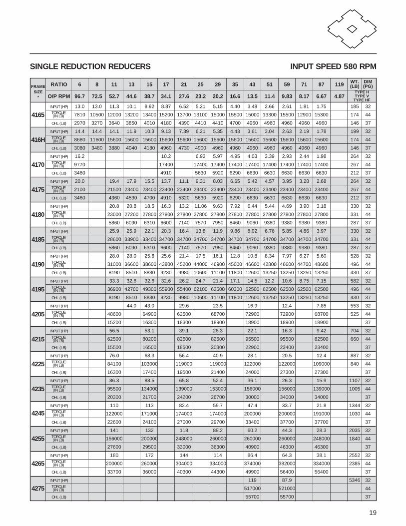
19
RATIO 6 8 11 13 15 17 21 25 29 35 43 51 59 71 87 119 WT. DIM(LB) (PG)
O/P RPM 96.7 72.5 52.7 44.6 38.7 34.1 27.6 23.2 20.2 16.6 13.5 11.4 9.83 8.17 6.67 4.87
INPUT (HP) 13.0 13.0 11.3 10.1 8.92 8.87 6.52 5.21 5.15 4.40 3.48 2.66 2.61 1.81 1.75 185 32
4165 7810 10500 12000 13200 13400 15200 13700 13100 15000 15500 15000 13300 15500 12900 15300 174 44
OHL (LB) 2970 3270 3640 3850 4010 4180 4390 4410 4410 4700 4960 4960 4960 4960 4960 146 37
INPUT (HP) 14.4 14.4 14.1 11.9 10.3 9.13 7.39 6.21 5.35 4.43 3.61 3.04 2.63 2.19 1.78 199 32
416H 8680 11600 15600 15600 15600 15600 15600 15600 15600 15600 15600 15600 15600 15600 15600 174 44
OHL (LB) 3080 3480 3880 4040 4180 4960 4730 4900 4960 4960 4960 4960 4960 4960 4960 146 37
INPUT (HP) 16.2 10.2 6.92 5.97 4.95 4.03 3.39 2.93 2.44 1.98 264 32
4170 9770 17400 17400 17400 17400 17400 17400 17400 17400 17400 267 44
OHL (LB) 3460 4910 5630 5920 6290 6630 6630 6630 6630 6630 212 37
INPUT (HP) 20.0 19.4 17.9 15.5 13.7 11.1 9.31 8.03 6.65 5.42 4.57 3.95 3.28 2.68 264 32
4175 2100 21500 23400 23400 23400 23400 23400 23400 23400 23400 23400 23400 23400 23400 267 44
OHL (LB) 3460 4360 4530 4700 4910 5320 5630 5920 6290 6630 6630 6630 6630 6630 212 37
INPUT (HP) 20.8 20.8 18.5 16.3 13.2 11.06 9.63 7.92 6.44 5.44 4.69 3.90 3.18 330 32
4180 23000 27200 27800 27800 27800 27800 27800 27800 27800 27800 27800 27800 27800 331 44
OHL (LB) 5860 6090 6310 6600 7140 7570 7950 8460 9060 9380 9380 9380 9380 287 37
INPUT (HP) 25.9 25.9 22.1 20.3 16.4 13.8 11.9 9.86 8.02 6.76 5.85 4.86 3.97 330 32
4185 28600 33900 33400 34700 34700 34700 34700 34700 34700 34700 34700 34700 34700 331 44
OHL (LB) 5860 6090 6310 6600 7140 7570 7950 8460 9060 9380 9380 9380 9380 287 37
INPUT (HP) 28.0 28.0 25.6 25.6 21.4 17.5 16.1 12.8 10.8 8.34 7.97 6.27 5.60 528 32
4190 31000 36600 38600 43800 45200 44000 46900 45000 46600 42800 46600 44700 48600 496 44
OHL (LB) 8190 8510 8830 9230 9980 10600 11100 11800 12600 13250 13250 13250 13250 430 37
INPUT (HP) 33.3 32.6 32.6 32.6 26.2 24.7 21.4 17.1 14.5 12.2 10.6 8.75 7.15 582 32
4195 36900 42700 49300 55900 55400 62100 62500 60300 62500 62500 62500 62500 62500 496 44
OHL (LB) 8190 8510 8830 9230 9980 10600 11100 11800 12600 13250 13250 13250 13250 430 37
INPUT (HP) 44.0 43.0 29.6 23.5 16.9 12.4 7.85 553 32
4205 48600 64900 62500 68700 72900 72900 68700 525 44
OHL (LB) 15200 16300 18300 18900 18900 18900 18900 37
INPUT (HP) 56.5 53.1 39.1 28.3 22.1 16.3 9.42 704 32
4215 62500 80200 82500 82500 95500 95500 82500 660 44
OHL (LB) 15500 16500 18500 20300 22900 23400 23400 37
INPUT (HP) 76.0 68.3 56.4 40.9 28.1 20.5 12.4 887 32
4225 84100 103000 119000 119000 122000 122000 109000 840 44
OHL (LB) 16300 17400 19500 21400 24000 27300 27300 37
INPUT (HP) 86.3 88.5 65.8 52.4 36.1 26.3 15.9 1107 32
4235 95500 134000 139000 153000 156000 156000 139000 1005 44
OHL (LB) 20300 21700 24200 26700 30000 34000 34000 37
INPUT (HP) 110 113 82.4 59.7 47.4 33.7 21.8 1344 32
4245 122000 171000 174000 174000 200000 200000 191000 1030 44
OHL (LB) 22600 24100 27000 29700 33400 37700 37700 37
INPUT (HP) 141 132 118 89.2 60.2 44.3 28.3 2035 32
4255 156000 200000 248000 260000 260000 260000 248000 1840 44
OHL (LB) 27600 29500 33000 36300 40900 46300 46300 37
INPUT (HP) 180 172 144 114 86.4 64.3 38.1 2552 32
4265 200000 260000 304000 334000 374000 382000 334000 2385 44
OHL (LB) 33700 36000 40300 44300 49900 56400 56400 37
INPUT (HP) 119 87.9 5346 32
4275 517000 521000 44
OHL (LB) 55700 55700 37
SINGLE REDUCTION REDUCERS INPUT SPEED 580 RPM
FRAMESIZE
*TYPE HTYPE V
TYPE HF
TORQUE(IN LB)
TORQUE(IN LB)
TORQUE(IN LB)
TORQUE(IN LB)
TORQUE(IN LB)
TORQUE(IN LB)
TORQUE(IN LB)
TORQUE(IN LB)
TORQUE(IN LB)
TORQUE(IN LB)
TORQUE(IN LB)
TORQUE(IN LB)
TORQUE(IN LB)
TORQUE(IN LB)
TORQUE(IN LB)
TORQUE(IN LB)

RATING TABLES
20
RATIO[17x6] [11x11] [15x11] [29x6] [17x11] [35x6] [21x11] [43x6] [17x17] [29x11] [59x6] [35x11] [29x15] [43x11] [29x17] [87x6] [35x17] [59x11]
102 121 165 174 187 210 231 258 289 319 354 385 435 473 493 522 595 649
O/P RPM 17.2 14.5 10.6 10.1 9.36 8.33 7.58 6.78 6.06 5.49 4.94 4.55 4.02 3.70 3.55 3.35 2.94 2.70
INPUT (HP) 0.12 0.12 0.12 0.12 0.12 0.12 0.12 0.12 0.12 0.12 0.124075 217 217 217 217 217 217 217 217 217 217 217DA
OHL (LB) 211 211 211 211 211 211 211 211 211 211 211
INPUT (HP) 0.12 0.12 0.12 0.12 0.12 0.12 0.12 0.12 0.12 0.12 0.12 0.124085 434 434 434 434 434 434 434 434 434 434 434 434DA
OHL (LB) 397 397 397 397 397 397 397 397 397 397 397 397
INPUT (HP) 0.36 0.30 0.22 0.21 0.19 0.17 0.15 0.14 0.13 0.12 0.12 0.12 0.12 0.12 0.12 0.12 0.12 0.124097 1130 1130 1130 1130 1130 1130 1130 1130 1130 1130 1130 1130 1130 1130 1130 1130 1130 1130DA
OHL (LB) 750 750 750 750 750 750 750 750 750 750 750 750 750 750 750 750 750 750
INPUT (HP) 0.54 0.59 0.43 0.41 0.38 0.34 0.31 0.27 0.25 0.22 0.20 0.18 0.16 0.15 0.14 0.14 0.12 0.124105 1680 2170 2170 2170 2170 2170 2170 2170 2170 2170 2170 2170 2170 2170 2170 2170 2170 2170DA
OHL (LB) 1210 1210 1210 1210 1210 1210 1210 1210 1210 1210 1210 1210 1210 1210 1210 1210 1210 1210
INPUT (HP) 1.67 1.41 1.03 0.98 0.91 0.81 0.74 0.66 0.59 0.53 0.48 0.44 0.39 0.36 0.34 0.33 0.29 0.264115 5200 5200 5200 5200 5200 5200 5200 5200 5200 5200 5200 5200 5200 5200 5200 5200 5200 5200DB
OHL (LB) 1940 1940 1940 1940 1940 1940 1940 1940 1940 1940 1940 1940 1940 1940 1940 1940 1940 1940
INPUT (HP) 2.50 2.11 1.55 1.47 1.36 1.21 1.11 0.99 0.88 0.80 0.72 0.66 0.59 0.54 0.52 0.49 0.43 0.394135 7810 7810 7810 7810 7810 7810 7810 7810 7810 7810 7810 7810 7810 7810 7810 7810 7810 7810DC
OHL (LB) 3250 3310 3310 3310 3310 3310 3310 3310 3310 3310 3310 3310 3310 3310 3310 3310 3310 3310
INPUT (HP) 1.89 1.80 1.67 1.48 1.35 1.21 1.08 0.98 0.88 0.81 0.72 0.66 0.63 0.60 0.52 0.484145 9550 9550 9550 9550 9550 9550 9550 9550 9550 9550 9550 9550 9550 9550 9550 9550DB
OHL (LB) 3600 3600 3600 3600 3600 3600 3600 3600 3600 3600 3600 3600 3600 3600 3600 3600
INPUT (HP) 5.01 4.22 3.09 2.94 2.73 2.43 2.21 1.97 1.76 1.60 1.44 1.32 1.17 1.08 1.03 0.98 0.86 0.794165 5600 15600 15600 15600 15600 15600 15600 15600 15600 15600 15600 15600 15600 15600 15600 15600 15600 15600DC
OHL (LB) 4610 4830 4960 4960 4960 4960 4960 4960 4960 4960 4960 4960 4960 4960 4960 4960 4960 4960
INPUT (HP) 6.80 5.83 4.63 4.41 4.09 3.64 3.31 2.96 2.65 2.40 2.16 1.99 1.76 1.62 1.55 1.46 1.28 1.184175 21300 21700 23400 23400 23400 23400 23400 23400 23400 23400 23400 23400 23400 23400 23400 23400 23400 23400DC
OHL (LB) 6230 6510 6630 6630 6630 6630 6630 6630 6630 6630 6630 6630 6630 6630 6630 6630 6630 6630
INPUT (HP) 11.1 7.74 6.87 6.54 6.06 5.40 4.91 4.39 3.93 3.56 3.20 2.95 2.60 2.40 2.30 2.17 1.90 1.754185 34700 28600 34700 34700 34700 34700 34700 34700 34700 34700 34700 34700 34700 34700 34700 34700 34700 34700DB
OHL (LB) 8360 8750 9380 9380 9380 9380 9380 9380 9380 9380 9380 9380 9380 9380 9380 9380 9380 9380
INPUT (HP) 4.98 4.48 4.12 3.65 3.36 3.22 3.04 2.67 2.454190 48600 48600 48600 48600 48600 48600 48600 48600 48600DA
OHL (LB) 13250 13250 13250 13250 13250 13250 13250 13250 13250
INPUT (HP) 3.134195 62500DA
OHL (LB) 13250
INPUT (HP) 13.5 13.1 11.7 11.4 10.6 9.64 8.82 7.90 6.88 6.36 5.73 5.27 4.69 4.29 4.11 3.88 3.414195 42300 48600 59000 60700 60800 62100 62500 62500 62500 62500 62500 62500 62500 62500 62500 62500 62500DB
OHL (LB) 11700 12200 13250 13260 13250 13250 13250 13250 13250 13250 13250 13250 13250 13250 13250 13250 13250
INPUT (HP)
4205DA
OHL (LB)
INPUT (HP) 12.8 13.0 9.23 7.04 6.68 5.16 5.00 4.30 3.654205 64900 68700 72900 68700 72900 68700 72900 68700 72900DB
OHL (LB) 18900 18900 18900 18900 18900 18900 18900 18900 18900
DOUBLE REDUCTION REDUCERS INPUT SPEED 1750 RPM
FRAMESIZE
† TYPE HTYPE V
TYPE HF
TORQUE(IN LB)
TORQUE(IN LB)
TORQUE(IN LB)
TORQUE(IN LB)
TORQUE(IN LB)
TORQUE(IN LB)
TORQUE(IN LB)
TORQUE(IN LB)
TORQUE(IN LB)
TORQUE(IN LB)
TORQUE(IN LB)
TORQUE(IN LB)
TORQUE(IN LB)
TORQUE(IN LB)
TORQUE(IN LB)
9 38
12 50
10 43
10 38
15 50
10 43
27 38
25 50
20 43
33 38
31 50
26 43
64 38
61 50
55 43
117 38
115 50
88 43
110 38
108 50
86 43
207 38
196 50
181 43
271 38
274 50
232 43
363 38
364 50
320 43
530 38
498 50
443 43
530 38
498 50
443 43
550 38
518 50
452 43
581 38
553 50
43
NOTES: MOTOR HP shown in the darker shaded areas is to overcome breakaway torque requirements in cold temperature or high inertiaapplications. It is recommended that a torque limiting device be used to protect the unit or driven machine.
*With the exception of units marked, all ratio combinations are shown in the same orders as the frame size designations.†Please refer to interchange table inside back cover.
WT.[LB]
DIM[PAGE]
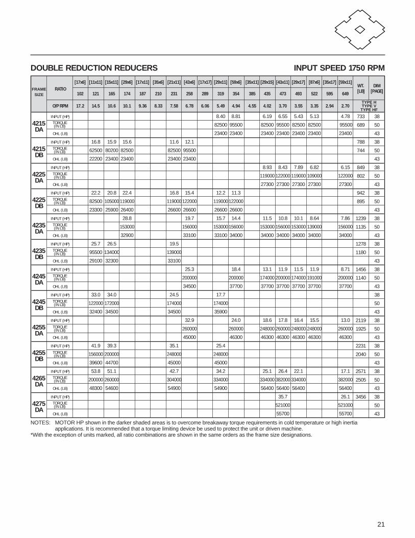
21
DOUBLE REDUCTION REDUCERS INPUT SPEED 1750 RPM
RATIO[17x6] [11x11] [15x11] [29x6] [17x11] [35x6] [21x11] [43x6] [17x17] [29x11] [59x6] [35x11] [29x15] [43x11] [29x17] [87x6] [35x17] [59x11]
102 121 165 174 187 210 231 258 289 319 354 385 435 473 493 522 595 649
O/P RPM 17.2 14.5 10.6 10.1 9.36 8.33 7.58 6.78 6.06 5.49 4.94 4.55 4.02 3.70 3.55 3.35 2.94 2.70
INPUT (HP) 8.40 8.81 6.19 6.55 5.43 5.13 4.784215 82500 95500 82500 95500 82500 82500 95500DA
OHL (LB) 23400 23400 23400 23400 23400 23400 23400
INPUT (HP) 16.8 15.9 15.6 11.6 12.14215 62500 80200 82500 82500 95500DB
OHL (LB) 22200 23400 23400 23400 23400
INPUT (HP) 8.93 8.43 7.89 6.82 6.154225 119000 122000 119000 109000 122000DA
OHL (LB) 27300 27300 27300 27300 27300
INPUT (HP) 22.2 20.8 22.4 16.8 15.4 12.2 11.34225 82500 105000 119000 119000 122000 119000 122000DB
OHL (LB) 23300 25900 26400 26600 26600 26600 26600
INPUT (HP) 28.8 19.7 15.7 14.4 11.5 10.8 10.1 8.64 7.864235 153000 156000 153000 156000 153000 156000 153000 139000 156000DA
OHL (LB) 32900 33100 33100 34000 34000 34000 34000 34000 34000
INPUT (HP) 25.7 26.5 19.54235 95500 134000 139000DB
OHL (LB) 29100 32300 33100
INPUT (HP) 25.3 18.4 13.1 11.9 11.5 11.9 8.714245 200000 200000 174000 200000 174000 191000 200000DA
OHL (LB) 34500 37700 37700 37700 37700 37700 37700
INPUT (HP) 33.0 34.0 24.5 17.74245 122000 172000 174000 174000DB
OHL (LB) 32400 34500 34500 35900
INPUT (HP) 32.9 24.0 18.6 17.8 16.4 15.5 13.04255 260000 260000 248000 260000 248000 248000 260000DA
OHL (LB) 45000 46300 46300 46300 46300 46300 46300
INPUT (HP) 41.9 39.3 35.1 25.44255 156000 200000 248000 248000DB
OHL (LB) 39600 44700 45000 45000
INPUT (HP) 53.8 51.1 42.7 34.2 25.1 26.4 22.1 17.14265 200000 260000 304000 334000 334000 382000 334000 382000DA
OHL (LB) 48300 54600 54900 54900 56400 56400 56400 56400
INPUT (HP) 35.7 26.14275 521000 521000DA
OHL (LB) 55700 55700
FRAMESIZE
TYPE HTYPE V
TYPE HF
TORQUE(IN LB)
TORQUE(IN LB)
TORQUE(IN LB)
TORQUE(IN LB)
TORQUE(IN LB)
TORQUE(IN LB)
TORQUE(IN LB)
TORQUE(IN LB)
TORQUE(IN LB)
TORQUE(IN LB)
TORQUE(IN LB)
TORQUE(IN LB)
NOTES: MOTOR HP shown in the darker shaded areas is to overcome breakaway torque requirements in cold temperature or high inertiaapplications. It is recommended that a torque limiting device be used to protect the unit or driven machine.
*With the exception of units marked, all ratio combinations are shown in the same orders as the frame size designations.
WT.[LB]
DIM[PAGE]
733 38
689 50
43
788 38
744 50
43
849 38
802 50
43
942 38
895 50
43
1239 38
1135 50
43
1278 38
1180 50
43
1456 38
1140 50
43
38
50
43
2119 38
1925 50
43
2231 38
2040 50
43
2571 38
2505 50
43
3456 38
50
43

RATING TABLES
22
RATIO[43x17] [29x29] [87x11] [59x17] [35x35] [43x29] [87x17] [43x35] [59x29] [43x43] [59x35] [59x43] [87x35] [59x59] [87x43] [87x59] [87x71] [87x87]
731 841 957 1003 1225 1247 1479 1505 1711 1849 2065 2537 3045 3481 3741 5133 6177 7569
O/P RPM 2.39 2.08 1.83 1.74 1.43 1.40 1.18 1.16 1.02 0.95 0.85 0.69 0.57 0.50 0.47 0.34 0.28 0.23
INPUT (HP) 0.12 0.12 0.12 0.12 0.12 0.124075 217 217 217 217 217 217DA
OHL (LB) 211 211 211 211 211 211
INPUT (HP) 0.12 0.12 0.12 0.12 0.12 0.12 0.12 0.12 0.12 0.124085 434 434 434 434 434 434 434 434 434 434DA
OHL (LB) 397 397 397 397 397 397 397 397 397 397
INPUT (HP) 0.12 0.12 0.12 0.12 0.12 0.12 0.12 0.12 0.12 0.12 0.12 0.12 0.12 0.12 0.12 0.124097 1130 1130 1130 1130 1130 1130 1130 1130 1130 1130 1130 1130 1130 1130 1130 1130DA
OHL (LB) 750 750 750 750 750 750 750 750 750 750 750 750 750 750 750 750
INPUT (HP) 0.12 0.12 0.12 0.12 0.12 0.12 0.12 0.12 0.12 0.12 0.12 0.12 0.12 0.12 0.12 0.124105 2170 2170 2170 2170 2170 2170 2170 2170 2170 2170 2170 2170 2170 2170 2170 2170DA
OHL (LB) 1210 1210 1210 1210 1210 1210 1210 1210 1210 1210 1210 1210 1210 1210 1210 1210
INPUT (HP) 0.23 0.20 0.18 0.17 0.14 0.14 0.12 0.12 0.12 0.12 0.12 0.12 0.12 0.12 0.12 0.12 0.12 0.124115 5200 5200 5200 5200 5200 5200 5200 5200 5200 5200 5200 5200 5200 5200 5200 5200 5200 5200DA
OHL (LB) 1940 1940 1940 1940 1940 1940 1940 1940 1940 1940 1940 1940 1940 1940 1940 1940 1940 1940
INPUT (HP) 0.35 0.30 0.27 0.25 0.25 0.25 0.25 0.25 0.25 0.25 0.25 0.25 0.25 0.25 0.25 0.25 0.25 0.254135 7810 7810 7810 7810 7810 7810 7810 7810 7810 7810 7810 7810 7810 7810 7810 7810 7810 7810DC
OHL (LB) 3310 3310 3310 3310 3310 3310 3310 3310 3310 3310 3310 3310 3310 3310 3310 3310 3310 3310
INPUT (HP) 0.43 0.37 0.33 0.31 0.25 0.25 0.25 0.25 0.25 0.25 0.25 0.25 0.25 0.25 0.25 0.25 0.25 0.254145 9550 9550 9550 9550 9550 9550 9550 9550 9550 9550 9550 9550 9550 9550 9550 9550 9550 9550DB
OHL (LB) 3600 3600 3600 3600 3600 3600 3600 3600 3600 3600 3600 3600 3600 3600 3600 3600 3600 3600
INPUT (HP) 0.70 0.61 0.53 0.51 0.50 0.50 0.50 0.50 0.50 0.50 0.50 0.50 0.50 0.50 0.50 0.50 0.50 0.504165 15600 15600 15600 15600 15600 15600 15600 15600 15600 15600 15600 15600 15600 15600 15600 15600 15600 1560DC
OHL (LB) 4960 4960 4960 4960 4960 4960 4960 4960 4960 4960 4960 4960 4960 4960 4960 4960 4960 4960
INPUT (HP) 1.04 0.91 0.80 0.76 0.62 0.61 0.52 0.51 0.50 0.50 0.50 0.50 0.50 0.50 0.50 0.50 0.50 0.504175 23400 23400 23400 23400 23400 23400 23400 23400 23400 23400 23400 23400 23400 23400 23400 23400 23400 23400DC
OHL (LB) 6630 6630 6630 6630 6630 6630 6630 6630 6630 6630 6630 6630 6630 6630 6630 6630 6630 6630
INPUT (HP) 1.55 1.35 1.19 1.13 1.00 1.00 1.00 1.00 1.00 1.00 1.00 1.00 1.00 1.00 1.00 1.00 1.00 1.004185 34700 34700 34700 34700 34700 34700 34700 34700 34700 34700 34700 34700 34700 34700 34700 34700 34700 34700DB
OHL (LB) 9380 9380 9380 9380 9380 9380 9380 9380 9380 9380 9380 9380 9380 9380 9380 9380 9380 9380
INPUT (HP) 2.17 1.89 1.66 1.58 1.30 1.27 1.07 1.05 1.00 1.00 1.00 1.00 1.00 1.00 1.00 1.00 1.00 1.004190 48600 48600 48600 48600 48600 48600 48600 48600 48600 48600 48600 48600 48600 48600 48600 48600 48600 48600DA
OHL (LB) 13250 13250 13250 13250 13250 13250 13250 13250 13250 13250 13250 13250 13250 13250 13250 13250 13250 13250
INPUT (HP) 2.77 2.41 2.12 2.02 1.66 1.62 1.37 1.34 1.18 1.10 1.00 1.00 1.00 1.00 1.00 1.00 1.00 1.004195 62500 62500 62500 62500 62500 62500 62500 62500 62500 62500 62500 62500 62500 62500 62500 62500 62500 62500DA
OHL (LB) 13250 13250 13250 13250 13250 13250 13250 13250 13250 13250 13250 13250 13250 13250 13250 13250 13250 13250
INPUT (HP)
4195DB
OHL (LB)
INPUT (HP) 2.00 2.00 2.00 2.00 2.00 2.00 2.00 2.00 2.00 2.00 2.00* 2.00 2.004205 72900 68700 72900 72900 72900 72900 72900 72900 72900 72900 72900 68700 68700DA
OHL (LB) 18900 18900 18900 18900 18900 18900 18900 18900 18900 18900 18900 18900 18900
INPUT (HP) 3.23 2.67 2.35 2.354205 72900 68700 68700 72900DB
OHL (LB) 18900 18900 18900 18900
DOUBLE REDUCTION REDUCERS INPUT SPEED 1750 RPM
FRAMESIZE
TYPE HTYPE V
TYPE HF
TORQUE(IN LB)
TORQUE(IN LB)
TORQUE(IN LB)
TORQUE(IN LB)
TORQUE(IN LB)
TORQUE(IN LB)
TORQUE(IN LB)
TORQUE(IN LB)
TORQUE(IN LB)
TORQUE(IN LB)
TORQUE(IN LB)
TORQUE(IN LB)
TORQUE(IN LB)
TORQUE(IN LB)
TORQUE(IN LB)
NOTES: MOTOR HP shown in the darker shaded areas is to overcome breakaway torque requirements in cold temperature or high inertiaapplications. It is recommended that a torque limiting device be used to protect the unit or driven machine.
*With the exception of units marked, all ratio combinations are shown in the same orders as the frame size designations.
WT.[LB]
DIM[PAGE]
9 38
12 50
10 43
10 38
15 50
10 43
27 38
25 50
20 43
33 38
31 50
26 43
64 38
61 50
55 43
117 38
115 50
88 43
110 38
108 50
86 43
207 38
196 50
181 43
271 38
274 50
232 43
363 38
364 50
320 43
530 38
498 50
443 43
530 38
498 50
443 43
565 38
537 50
43
581 38
533 50
43

23
DOUBLE REDUCTION REDUCERS INPUT SPEED 1750 RPM
RATIO[43x17] [29x29] [87x11] [59x17] [35x35] [43x29] [87x17] [43x35] [59x29] [43x43] [59x35] [59x43] [87x35] [59x59] [87x43] [87x59] [87x71] [87x87]
731 841 957 1003 1225 1247 1479 1505 1711 1849 2065 2537 3045 3481 3741 5133 6177 7569
O/P RPM 2.39 2.08 1.83 1.74 1.43 1.40 1.18 1.16 1.02 0.95 0.85 0.69 0.57 0.50 0.47 0.34 0.28 0.23
INPUT (HP) 4.23 3.18 2.80 3.08 2.48 2.00 2.00 2.00 2.00 2.00 2.00 2.00 2.00 2.00 2.00 2.00 2.004215 95500 82500 82500 95500 95500 82500 95500 95500 95500 95500 95500 82500 95500 95500 95500 82500 82500DA
OHL (LB) 23400 23400 23400 23400 23400 23400 23400 23400 23400 23400 23400 23400 23400 23400 23400 23400 23400
INPUT (HP)
4215DB
OHL (LB)
INPUT (HP) 5.44 4.62 3.72 3.96 3.19 3.00 3.00 3.00 3.00 3.00 3.00 3.00 3.00 3.00 3.00 3.00 3.004225 122000 119000 109000 122000 122000 109000 122000 122000 122000 122000 122000122000 122000 122000 122000 109000 109000DA
OHL (LB) 27300 27300 27300 27300 27300 27300 27300 27300 27300 27300 27300 27300 27300 27300 27300 27300 27300
INPUT (HP)
4225DB
OHL (LB)
INPUT (HP) 6.96 5.94 4.72 5.07 4.08 3.04 3.00 3.00 3.00 3.00 3.00 3.00 3.00 3.00* 3.00* 3.00 3.004235 156000 153000 139000 156000 156000 139000 156000 156000 156000 156000 156000156000 156000 156000 156000 139000 139000DA
OHL (LB) 34000 34000 34000 34000 34000 34000 34000 34000 34000 34000 34000 34000 34000 34000 34000 34000 34000
INPUT (HP)
4235DB
OHL (LB)
INPUT (HP) 8.92 6.71 6.52 6.50 5.23 4.21 3.74 3.29 3.07 3.00 3.00 3.00 3.00 3.00* 3.00* 3.00 3.004245 200000 174000 191000 200000 200000 191000 200000 200000 200000 200000 200000191000 200000 200000 200000 191000 191000DA
OHL (LB) 37700 37700 37700 37700 37700 37700 37700 37700 37700 37700 37700 37700 37700 37700 37700 37700 37700
INPUT (HP)
4245DB
OHL (LB)
INPUT (HP) 11.5 9.63 8.47 8.39 6.75 5.46 5.59 5.00 5.00 5.00 5.00 5.00 5.00 5.00* 5.00* 5.00 5.004255 260000 248000 248000 260000 260000 248000 260000 260000 260000 260000 260000248000 260000 260000 260000 248000 248000DA
OHL (LB) 46300 46300 46300 46300 46300 46300 46300 46300 46300 46300 46300 46300 46300 46300 46300 46300 46300
INPUT (HP)
4255DB
OHL (LB)
INPUT (HP) 17.0 13.0 11.4 12.4 9.98 7.50 7.50 7.50 7.50 7.50 7.50 7.50 7.50 7.50* 7.50* 7.50 7.504265 382000 334000 334000 382000 382000 334000 382000 382000 382000 382000 382000334000 382000 382000 382000 334000 334000DA
OHL (LB) 56400 56400 56400 56400 56400 56400 56400 56400 56400 56400 56400 56400 56400 56400 56400 56400 56400
INPUT (HP) 23.1 16.8 13.5 11.2 10.0 10.0 10.0 10.0 10.0 10.0* 10.0*4275 521000 521000 521000 521000 521000 521000 521000 521000 521000 521000 521000DA
OHL (LB) 55700 55700 55700 55700 55700 55700 55700 55700 55700 55700 55700
FRAMESIZE
TYPE HTYPE V
TYPE HF
TORQUE(IN LB)
TORQUE(IN LB)
TORQUE(IN LB)
TORQUE(IN LB)
TORQUE(IN LB)
TORQUE(IN LB)
TORQUE(IN LB)
TORQUE(IN LB)
TORQUE(IN LB)
TORQUE(IN LB)
TORQUE(IN LB)
TORQUE(IN LB)
NOTES: MOTOR HP shown in the darker shaded areas is to overcome breakaway torque requirements in cold temperature or high inertiaapplications. It is recommended that a torque limiting device be used to protect the unit or driven machine.
*With the exception of units marked, all ratio combinations are shown in the same orders as the frame size designations.
WT.[LB]
DIM[PAGE]
733 38
689 50
43
849 38
802 50
43
1239 38
1135 50
43
1456 38
1140 50
43
2119 38
1925 50
43
2671 38
2505 50
43
3456 38
50
43

24
RATIO[17x6] [11x11] [15x11] [29x6] [17x11] [35x6] [21x11] [43x6] [17x17] [29x11] [59x6] [35x11] [29x15] [43x11] [29x17] [87x6] [35x17] [59x11]
102 121 165 174 187 210 231 258 289 319 354 385 435 473 493 522 595 649
O/P RPM 11.4 9.63 7.06 6.70 6.23 5.55 5.04 4.52 4.03 3.65 3.29 3.03 2.68 2.46 2.36 2.23 1.96 1.80
INPUT (HP) 0.12 0.12 0.12 0.12 0.12 0.12 0.12 0.12 0.12 0.124075 217 217 217 217 217 217 217 217 217 217DA
OHL (LB) 211 211 211 211 211 211 211 211 211 211
INPUT (HP) 0.12 0.12 0.12 0.12 0.12 0.12 0.12 0.12 0.12 0.12 0.124085 434 434 434 434 434 434 434 434 434 434 434DA
OHL (LB) 397 397 397 397 397 397 397 397 397 397 397
INPUT (HP) 0.24 0.20 0.15 0.14 0.13 0.12 0.12 0.12 0.12 0.12 0.12 0.12 0.12 0.12 0.12 0.12 0.12 0.124097 1130 1130 1130 1130 1130 1130 1130 1130 1130 1130 1130 1130 1130 1130 1130 1130 1130 1130DA
OHL (LB) 750 750 750 750 750 750 750 750 750 750 750 750 750 750 750 750 750 750
INPUT (HP) 0.46 0.39 0.28 0.27 0.25 0.22 0.20 0.18 0.16 0.15 0.13 0.12 0.12 0.12 0.12 0.12 0.12 0.124105 2170 2170 2170 2170 2170 2170 2170 2170 2170 2170 2170 2170 2170 2170 2170 2170 2170 2170DA
OHL (LB) 1210 1210 1210 1210 1210 1210 1210 1210 1210 1210 1210 1210 1210 1210 1210 1210 1210 1210
INPUT (HP) 1.11 0.93 0.68 0.65 0.60 0.54 0.49 0.44 0.39 0.35 0.32 0.29 0.26 0.24 0.23 0.22 0.19 0.174115 5200 5200 5200 5200 5200 5200 5200 5200 5200 5200 5200 5200 5200 5200 5200 5200 5200 5200DB
OHL (LB) 1940 1940 1940 1940 1940 1940 1940 1940 1940 1940 1940 1940 1940 1940 1940 1940 1940 1940
INPUT (HP) 1.65 1.39 1.02 0.97 0.90 0.80 0.73 0.65 0.58 0.53 0.48 0.44 0.39 0.36 0.34 0.32 0.28 0.264135 7810 7810 7810 7810 7810 7810 7810 7810 7810 7810 7810 7810 7810 7810 7810 7810 7810 7810DC
OHL (LB) 3310 3310 3310 3310 3310 3310 3310 3310 3310 3310 3310 3310 3310 3310 3310 3310 3310 3310
INPUT (HP) 1.25 1.19 1.10 0.99 0.89 0.80 0.71 0.65 0.58 0.54 0.50 0.50 0.50 0.50 0.50 0.504145 9550 9550 9550 9550 9550 9550 9550 9550 9550 9550 9550 9550 9550 9550 9550 9550DB
OHL (LB) 3600 3600 3600 3600 3600 3600 3600 3600 3600 3600 3600 3600 3600 3600 3600 3600
INPUT (HP) 3.30 2.79 2.04 1.94 1.80 1.61 1.46 1.31 1.17 1.06 0.95 0.88 0.78 0.71 0.68 0.65 0.57 0.524165 15600 15600 15600 15600 15600 15600 15600 15600 15600 15600 15600 15600 15600 15600 15600 15600 15600 15600DC
OHL (LB) 4960 4960 4960 4960 4960 4960 4960 4960 4960 4960 4960 4960 4960 4960 4960 4960 4960 4960
INPUT (HP) 4.99 3.89 3.09 2.93 2.72 2.43 2.20 1.97 1.76 1.60 1.44 1.32 1.17 1.08 1.03 0.98 0.86 0.784175 23400 21700 23400 23400 23400 23400 23400 23400 23400 23400 23400 23400 23400 23400 23400 23400 23400 23400DC
OHL (LB) 6630 6630 6630 6630 6630 6630 6630 6630 6630 6630 6630 6630 6630 6630 6630 6630 6630 6630
INPUT (HP) 7.39 5.13 4.57 4.33 4.03 3.59 3.27 2.92 2.61 2.37 2.13 1.96 1.73 1.60 1.53 1.45 1.27 1.164185 34700 28600 34700 34700 34700 34700 34700 34700 34700 34700 34700 34700 34700 34700 34700 34700 34700 34700DB
OHL (LB) 9380 9380 9380 9380 9380 9380 9380 9380 9380 9380 9380 9380 9380 9380 9380 9380 9380 9380
INPUT (HP) 5.24 4.87 4.34 3.92 3.53 3.15 3.31 2.99 2.75 2.42 2.23 2.14 2.02 1.78 1.634190 41900 41900 41900 41900 41900 41900 48600 48600 48600 48600 48600 48600 48600 48600 48600DA
OHL (LB) 13250 13250 13250 13250 13250 13250 13250 13250 13250 13250 13250 13250 13250 13250 13250
INPUT (HP) 2.094195 62500DA
OHL (LB) 13250
INPUT (HP) 12.9 8.72 7.77 7.80 7.06 6.46 5.87 5.26 4.57 4.23 3.81 3.51 3.11 2.85 2.74 2.58 2.274195 60800 48600 59000 62500 60800 62500 62500 62500 60800 62500 62500 62500 62500 62500 62500 62500 62500DB
OHL (LB) 13250 13250 13250 13250 13250 13250 13250 13250 13250 13250 13250 13250 13250 13250 13250 13250 13250
INPUT (HP)
4205DA
OHL (LB)
INPUT (HP) 8.50 8.53 5.84 5.24 4.65 4.45 3.41 3.33 3.01 2.84 2.434205 64900 68700 62500 62500 68700 72900 68700 72900 68700 68700 72900DB
OHL (LB) 18900 18900 18900 18900 18900 18900 18900 18900 18900 18900 18900
DOUBLE REDUCTION REDUCERS INPUT SPEED 1165 RPM
FRAMESIZE
TYPE HTYPE V
TYPE HF
TORQUE(IN LB)
TORQUE(IN LB)
TORQUE(IN LB)
TORQUE(IN LB)
TORQUE(IN LB)
TORQUE(IN LB)
TORQUE(IN LB)
TORQUE(IN LB)
TORQUE(IN LB)
TORQUE(IN LB)
TORQUE(IN LB)
TORQUE(IN LB)
TORQUE(IN LB)
TORQUE(IN LB)
TORQUE(IN LB)
NOTES: MOTOR HP shown in the darker shaded areas is to overcome breakaway torque requirements in cold temperature or high inertiaapplications. It is recommended that a torque limiting device be used to protect the unit or driven machine.
*With the exception of units marked, all ratio combinations are shown in the same orders as the frame size designations.
WT.[LB]
DIM[PAGE]
9 38
12 50
10 43
10 38
15 50
10 43
27 38
25 50
20 43
33 38
31 50
26 43
64 38
61 50
55 43
117 38
115 50
88 43
110 38
108 50
86 43
207 38
196 50
181 43
271 38
274 50
232 43
363 38
364 50
320 43
530 38
498 50
443 43
530 38
498 50
443 43
550 38
518 50
452 43
581 38
553 50
43
RATING TABLES

25
DOUBLE REDUCTION REDUCERS INPUT SPEED 1165 RPM
RATIO[17x6] [11x11] [15x11] [29x6] [17x11] [35x6] [21x11] [43x6] [17x17] [29x11] [59x6] [35x11] [29x15] [43x11] [29x17] [87x6] [35x17] [59x11]
102 121 165 174 187 210 231 258 289 319 354 385 435 473 493 522 595 649
O/P RPM 11.4 9.63 7.06 6.70 6.23 5.55 5.04 4.52 4.03 3.65 3.29 3.03 2.68 2.46 2.36 2.23 1.96 1.80
INPUT (HP) 5.58 5.03 4.10 4.36 3.61 3.41 3.194215 82500 82500 82500 95500 82500 82500 95500DA
OHL (LB) 23400 23400 23400 23400 23400 23400 23400
INPUT (HP) 13.2 10.5 10.2 7.71 6.914215 62500 80200 82500 82500 82500DB
OHL (LB) 23400 23400 23400 23400 23400
INPUT (HP) 5.91 5.57 5.21 4.51 4.064225 119000 122000 119000 109000 122000DA
OHL (LB) 26600 26600 26600 26600 26600
INPUT (HP) 14.7 13.7 14.8 11.1 10.2 8.06 7.454225 82500 105000 119000 119000 122000 119000 122000DB
OHL (LB) 26600 26900 27000 27300 27300 27300 27300
INPUT (HP) 19.0 13.2 10.4 9.58 7.60 7.16 6.70 5.75 5.244235 153000 156000 153000 156000 153000 156000 153000 139000 156000DA
OHL (LB) 33600 34000 34000 34000 34000 34000 34000 34000 34000
INPUT (HP) 17.1 17.5 13.04235 95500 134000 139000DB
OHL (LB) 33100 33500 34000
INPUT (HP) 14.7 10.6 8.65 9.18 7.61 7.90 6.724245 174000 174000 174000 200000 174000 191000 200000DA
OHL (LB) 37700 37700 37700 37700 37700 33700 33700
INPUT (HP) 2.18 22.5 16.3 11.84245 122000 172000 174000 174000DB
OHL (LB) 34700 36400 37700 37700
INPUT (HP) 16.8 12.2 11.9 10.9 10.3 8.684255 260000 260000 260000 248000 248000 260000DA
OHL (LB) 46300 46300 46300 46300 46300 46300
INPUT (HP) 27.9 26.2 23.2 16.84255 156000 200000 248000 248000DB
OHL (LB) 44800 45600 46300 46300
INPUT (HP) 35.7 34.0 28.4 22.6 16.7 17.4 14.6 12.74265 200000 260000 304000 334000 334000 382000 334000 382000DA
OHL (LB) 54700 55700 56400 56400 56400 56400 56400 56400
INPUT (HP) 23.8 17.44275 521000 521000DA
OHL (LB) 55700 55700
FRAMESIZE
* TYPE HTYPE V
TYPE HF
TORQUE(IN LB)
TORQUE(IN LB)
TORQUE(IN LB)
TORQUE(IN LB)
TORQUE(IN LB)
TORQUE(IN LB)
TORQUE(IN LB)
TORQUE(IN LB)
TORQUE(IN LB)
TORQUE(IN LB)
TORQUE(IN LB)
TORQUE(IN LB)
NOTES: MOTOR HP shown in the darker shaded areas is to overcome breakaway torque requirements in cold temperature or high inertiaapplications. It is recommended that a torque limiting device be used to protect the unit or driven machine.
*With the exception of units marked, all ratio combinations are shown in the same orders as the frame size designations.
WT.[LB]
DIM[PAGE]
733 38
689 50
43
788 38
744 50
43
849 38
802 50
43
942 38
895 50
43
1239 38
1135 50
43
1456 38
1140 50
43
1516 38
1200 50
43
2119 38
1925 50
43
2331 38
2040 50
43
2671 38
2505 50
43
3456 38
50
43

RATING TABLES
26
RATIO[43x17] [29x29] [87x11] [59x17] [35x35] [43x29] [87x17] [43x35] [59x29] [43x43] [59x35] [59x43] [87x35] [59x59] [87x43] [87x59] [87x71] [87x87]
731 841 957 1003 1225 1247 1479 1505 1711 1849 2065 2537 3045 3481 3741 5133 6177 7569
O/P RPM 1.59 1.39 1.22 1.16 0.95 0.93 0.79 0.77 0.68 0.63 0.56 0.46 0.38 0.33 0.31 0.23 0.19 0.15
INPUT (HP) 0.12 0.12 0.12 0.12 0.12 0.124075 217 217 217 217 217 217DA
OHL (LB) 211 211 211 211 211 211
INPUT (HP) 0.12 0.12 0.12 0.12 0.12 0.12 0.12 0.12 0.12 0.124085 434 434 434 434 434 434 434 434 434 434DA
OHL (LB) 397 397 397 397 397 397 397 397 397 397
INPUT (HP) 0.12 0.12 0.12 0.12 0.12 0.12 0.12 0.12 0.12 0.12 0.12 0.12 0.12 0.12 0.12 0.124097 1130 1130 1130 1130 1130 1130 1130 1130 1130 1130 1130 1130 1130 1130 1130 1130DA
OHL (LB) 750 750 750 750 750 750 750 750 750 750 750 750 750 750 750 750
INPUT (HP) 0.12 0.12 0.12 0.12 0.12 0.12 0.12 0.12 0.12 0.12 0.12 0.12 0.12 0.12 0.12 0.124105 2170 2170 2170 2170 2170 2170 2170 2170 2170 2170 2170 2170 2170 2170 2170 2170DA
OHL (LB) 1210 1210 1210 1210 1210 1210 1210 1210 1210 1210 1210 1210 1210 1210 1210 1210
INPUT (HP) 0.15 0.13 0.12 0.12 0.12 0.12 0.12 0.12 0.12 0.12 0.12 0.12 0.12 0.12 0.12 0.12 0.12 0.124115 5200 5200 5200 5200 5200 5200 5200 5200 5200 5200 5200 5200 5200 5200 5200 5200 5200 5200DB
OHL (LB) 1940 1940 1940 1940 1940 1940 1940 1940 1940 1940 1940 1940 1940 1940 1940 1940 1940 1940
INPUT (HP) 0.25 0.25 0.25 0.25 0.25 0.25 0.25 0.25 0.25 0.25 0.25 0.25 0.25 0.25 0.25 0.25 0.25 0.254135 7810 7810 7810 7810 7810 7810 7810 7810 7810 7810 7810 7810 7810 7810 7810 7810 7810 7810DC
OHL (LB) 3310 3310 3310 3310 3310 3310 3310 3310 3310 3310 3310 3310 3310 3310 3310 3310 3310 3310
INPUT (HP) 0.50 0.50 0.50 0.50 0.50 0.50 0.50 0.50 0.50 0.50 0.50 0.50 0.50 0.50 0.50 0.50 0.50 0.504145 9550 9550 9550 9550 9550 9550 9550 9550 9550 9550 9500 9500 9500 9500 9500 9500 9500 9500DB
OHL (LB) 3600 3600 3600 3600 3600 3600 3600 3600 3600 3600 3600 3600 3600 3600 3600 3600 3600 3600
INPUT (HP) 0.50 0.50 0.50 0.50 0.50 0.50 0.50 0.50 0.50 0.50 0.50 0.50 0.50 0.50 0.50 0.50 0.50 0.504165 15600 15600 15600 15600 15600 15600 15600 15600 15600 15600 15600 15600 15600 15600 15600 15600 15600 1560DC
OHL (LB) 4960 4960 4960 4960 4960 4960 4960 4960 4960 4960 4960 4960 4960 4960 4960 4960 4960 4960
INPUT (HP) 0.70 0.61 0.53 0.51 0.50 0.50 0.50 0.50 0.50 0.50 0.50 0.50 0.50 0.50 0.50 0.504175 23400 23400 23400 23400 23400 23400 23400 23400 23400 23400 23400 23400 23400 23400 23400 23400 23400 23400DC
OHL (LB) 6630 6630 6630 6630 6630 6630 6630 6630 6630 6630 6630 6630 6630 6630 6630 6630 6630 6630
INPUT (HP) 1.03 1.00 1.00 1.00 1.00 1.00 1.00 1.00 1.00 1.00 1.00 1.00 1.00 1.00 1.00 1.00 1.00 1.004185 34700 34700 34700 34700 34700 34700 34700 34700 34700 34700 34700 34700 34700 34700 34700 34700 34700 34700DB
OHL (LB) 9380 9380 9380 9380 9380 9380 9380 9380 9380 9380 9380 9380 9380 9380 9380 9380 9380 9380
INPUT (HP) 1.45 1.26 1.10 1.05 1.00 1.00 1.00 1.00 1.00 1.00 1.00 1.00 1.00 1.00 1.00 1.00 1.00 1.004190 48600 48600 48600 48600 48600 48600 48600 48600 48600 48600 48600 48600 48600 48600 48600 48600 48600 48600DA
OHL (LB) 13250 13250 13250 13250 13250 13250 13250 13250 13250 13250 13250 13250 13250 13250 13250 13250 13250 13250
INPUT (HP) 1.84 1.61 1.41 1.34 1.10 1.08 1.00 1.00 1.00 1.00 1.00 1.00 1.00 1.00 1.00 1.00 1.00 1.004195 62500 62500 62500 62500 62500 62500 62500 62500 62500 62500 62500 62500 62500 62500 62500 62500 62500 62500DA
OHL (LB) 13250 13250 13250 13250 13250 13250 13250 13250 13250 13250 13250 13250 13250 13250 13250 13250 13250 13250
INPUT (HP)
4195DB
OHL (LB)
INPUT (HP) 2.00 2.00 2.00 2.00 2.00 2.00 2.00 2.00 2.00 2.00 2.00* 2.00 2.004205 72900 68700 72900 72900 72900 72900 72900 72900 72900 72900 72900 68700 68700DA
OHL (LB) 18900 18900 18900 18900 18900 18900 18900 18900 18900 18900 18900 18900 18900
INPUT (HP) 2.15 2.00 2.00 2.004205 72900 68700 68700 72900DB
OHL (LB) 18900 18900 18900 18900
DOUBLE REDUCTION REDUCERS INPUT SPEED 1165 RPM
FRAMESIZE
* TYPE HTYPE V
TYPE HF
TORQUE(IN LB)
TORQUE(IN LB)
TORQUE(IN LB)
TORQUE(IN LB)
TORQUE(IN LB)
TORQUE(IN LB)
TORQUE(IN LB)
TORQUE(IN LB)
TORQUE(IN LB)
TORQUE(IN LB)
TORQUE(IN LB)
TORQUE(IN LB)
TORQUE(IN LB)
TORQUE(IN LB)
TORQUE(IN LB)
NOTES: MOTOR HP shown in the darker shaded areas is to overcome breakaway torque requirements in cold temperature or high inertiaapplications. It is recommended that a torque limiting device be used to protect the unit or driven machine.
*With the exception of units marked, all ratio combinations are shown in the same orders as the frame size designations.
WT.[LB]
DIM[PAGE]
9 38
12 50
10 43
10 38
15 50
10 43
27 38
25 50
20 43
33 38
31 50
26 43
64 38
61 50
55 43
117 38
115 50
88 43
110 38
108 50
86 43
207 38
196 50
181 43
271 38
274 50
232 43
363 38
364 50
320 43
530 38
498 50
443 43
530 38
498 50
443 43
565 38
537 50
43
581 38
533 50
43

27
DOUBLE REDUCTION REDUCERS INPUT SPEED 1165 RPM
RATIO[43x17] [29x29] [87x11] [59x17] [35x35] [43x29] [87x17] [43x35] [59x29] [43x43] [59x35] [59x43] [87x35] [59x59] [87x43] [87x59] [87x71] [87x87]
731 841 957 1003 1225 1247 1479 1505 1711 1849 2065 2537 3045 3481 3741 5133 6177 7569
O/P RPM 1.59 1.39 1.22 1.16 0.95 0.93 0.79 0.77 0.68 0.63 0.56 0.46 0.38 0.33 0.31 0.23 0.19 0.15
INPUT (HP) 2.82 2.13 2.00 2.00 2.00 2.00 2.00 2.00 2.00 2.00 2.00 2.00 2.00 2.00 2.00 2.00 2.00*4215 95500 82500 82500 95500 95500 82500 95500 95500 95000 95500 95500 82500 95500 95500 95500 82500 82500DA
OHL (LB) 23400 23400 23400 23400 23400 23400 23400 23400 23400 23400 23400 23400 23400 23400 23400 23400 23400
INPUT (HP)
4215DB
OHL (LB)
INPUT (HP) 3.60 3.06 3.00 3.00 3.00 3.00 3.00 3.00 3.00 3.00 3.00 3.00 3.00 3.00* 3.00* 3.00 3.004225 122000 119000 109000 122000 122000 109000 122000 122000 122000 122000 122000122000 122000 122000 122000 109000 109000DA
OHL (LB) 27300 27300 27300 27300 27300 27300 27300 27300 27300 27300 27300 27300 27300 27300 27300 27300 27300
INPUT (HP)
4225DB
OHL (LB)
INPUT (HP) 4.63 3.93 3.14 3.38 3.00 3.00 3.00 3.00 3.00 3.00 3.00 3.00 3.00 3.00* 3.00* 3.00 3.004235 156000 153000 139000 156000 156000 139000 156000 156000 156000 156000 156000156000 156000 156000 156000 139000 139000DA
OHL (LB) 34000 34000 34000 34000 34000 34000 34000 34000 34000 34000 34000 34000 34000 34000 34000 34000 34000
INPUT (HP)
4235DB
OHL (LB)
INPUT (HP) 5.94 4.49 4.31 4.33 3.47 3.00 3.00 3.00 3.00 3.00 3.00 3.00 3.00 3.00* 3.00* 3.00 3.004245 200000 174000 191000 200000 200000 191000 200000 200000 200000 200000 200000191000 200000 200000 200000 191000 191000DA
OHL (LB) 37700 37700 37700 37700 37700 37700 37700 37700 37700 37700 37700 37700 37700 37700 37700 37700 37700
INPUT (HP)
4245DB
OHL (LB)
INPUT (HP) 7.67 6.37 5.60 5.59 5.00 5.00 5.00 5.00 5.00 5.00 5.00 5.00 5.00 5.00* 5.00* 5.00 5.004255 260000 248000 248000 260000 260000 248000 260000 260000 260000 260000 260000260000 260000 260000 260000 248000 248000DA
OHL (LB) 46300 46300 46300 46300 46300 46300 46300 46300 46300 46300 46300 46300 46300 46300 46300 46300 46300
INPUT (HP)
4255DB
OHL (LB)
INPUT (HP) 11.3 8.58 7.54 8.23 7.50 7.50 7.50 7.50 7.50 7.50 7.50 7.50 7.50 7.50* 7.50* 7.50 7.504265 382000 334000 334000 382000 382000 334000 382000 382000 382000 382000 382000334000 382000 382000 382000 334000 334000DA
OHL (LB) 56400 56400 56400 56400 56400 56400 56400 56400 56400 56400 56400 56400 56400 56400 56400 56400 56400
INPUT (HP) 15.4 11.2 10.0 10.0 10.0 10.0 10.0 10.0 10.0 10.0* 10.0*4275 521000 521000 521000 521000 521000 521000 521000 521000 521000 521000 521000DA
OHL (LB) 55700 55700 55700 55700 55700 55700 55700 55700 55700 55700 55700
FRAMESIZE
* TYPE HTYPE V
TYPE HF
TORQUE(IN LB)
TORQUE(IN LB)
TORQUE(IN LB)
TORQUE(IN LB)
TORQUE(IN LB)
TORQUE(IN LB)
TORQUE(IN LB)
TORQUE(IN LB)
TORQUE(IN LB)
TORQUE(IN LB)
TORQUE(IN LB)
TORQUE(IN LB)
NOTES: MOTOR HP shown in the darker shaded areas is to overcome breakaway torque requirements in cold temperature or high inertiaapplications. It is recommended that a torque limiting device be used to protect the unit or driven machine.
*With the exception of units marked, all ratio combinations are shown in the same orders as the frame size designations.
WT.[LB]
DIM[PAGE]
733 38
689 50
43
849 38
802 50
43
1239 38
1135 50
43
1456 38
1140 50
43
2119 38
1925 50
43
2671 38
2505 50
43
3456 38
50
43

28
Combination Total Combination Total Combination Total Combination TotalRatio Ratio Ratio Ratio
6 x 11 x 15 990 6 x 29 x 43 7482 17 x 17 x 87 25143 17 x 59 x 87 87261
6 x 11 x 17 1122 11 x 17 x 43 8041 17 x 35 x 43 25585 29 x 35 x 87 88305
11 x 11 x 11 1331 17 x 17 x 29 8381 11 x 29 x 87 27753 35 x 43 x 59 88795
6 x 11 x 21 1386 6 x 17 x 87 8874 11 x 43 x 59 27907 29 x 59 x 59 100949
6 x 17 x 17 1734 6 x 45 x 43 9030 17 x 29 x 59 29087 35 x 35 x 87 106575
11 x 11 x 15 1815 11 x 29 x 29 9251 29 x 29 x 35 29435 29 x 43 x 87 108489
6 x 11 x 29 1914 17 x 17 x 35 10115 17 x 43 x 43 31433 43 x 43 x 59 109091
11 x 11 x 17 2057 6 x 29 x 59 10266 11 x 35 x 87 33495 35 x 59 x 59 121835
6 x 17 x 21 2142 11 x 11 x 87 10527 17 x 35 x 59 35105 17 x 87 x 87 128673
6 x 11 x 35 2310 11 x 17 x 59 11033 29 x 35 x 35 35525 35 x 43 x 87 130935
11 x 11 x 21 2541 6 x 43 x 43 11094 29 x 29 x 43 36163 29 x 59 x 87 148857
6 x 11 x 43 2838 11 x 29 x 35 11165 11 x 59 x 59 38291 43 x 59 x 59 149683
6 x 17 x 29 2958 6 x 35 x 59 12390 11 x 43 x 87 41151 43 x 43 x 87 160863
11 x 17 x 17 3179 17 x 17 x 43 12427 35 x 35 x 35 42875 35 x 59 x 87 179655
11 x 11 x 29 3509 11 x 35 x 35 13475 17 x 29 x 87 42891 59 x 59 x 59 205379
6 x 17 x 35 3570 11 x 29 x 43 13717 17 x 43 x 59 43129 29 x 87 x 87 219501
6 x 11 x 59 3894 17 x 29 x 29 14297 29 x 35 x 43 43645 43 x 59 x 87 220719
11 x 17 x 21 3927 6 x 29 x 87 15138 29 x 29 x 59 49619 35 x 87 x 87 264915
11 x 11 x 35 4235 6 x 43 x 59 15222 17 x 35 x 87 51765 59 x 59 x 87 302847
6 x 17 x 43 4386 11 x 17 x 87 16269 35 x 35 x 43 52675 43 x 87 x 87 325467
17 x 17 x 17 4913 11 x 35 x 43 16555 29 x 43 x 43 53621 59 x 87 x 87 446571
6 x 29 x 29 5046 17 x 17 x 59 17051 11 x 59 x 87 56463 87 x 87 x 87 658503
11 x 11 x 43 5203 17 x 29 x 35 17255 17 x 59 x 59 59177
11 x 17 x 29 5423 6 x 35 x 87 18270 29 x 35 x 59 59885
6 x 11 x 87 5742 11 x 29 x 59 18821 17 x 43 x 87 63597
6 x 17 x 59 6018 11 x 43 x 43 20339 35 x 43 x 43 64715
17 x 17 x 21 6069 17 x 35 x 35 20825 35 x 35 x 59 72275
6 x 29 x 35 6090 17 x 29 x 43 21199 29 x 29 x 87 73167
11 x 17 x 35 6545 6 x 43 x 87 22446 29 x 43 x 59 73573
11 x 11 x 59 7139 11 x 35 x 59 22715 43 x 43 x 43 79507
6 x 35 x 35 7350 29 x 29 x 29 24389 11 x 87 x 87 83259
STANDARD RATIO COMBINATIONS
MULTIPLE REDUCTION UNITSDOUBLE REDUCTION
Combination Total Combination Total Combination Total Combination TotalRatio Ratio Ratio Ratio
6 x 17 102 6 x 59 354 11 x 87 957 43 x 59 2537
11 x 11 121 11 x 35 385 17 x 59 1003 51 x 51 2601
6 x 21 126 15 x 29 435 35 x 35 1225 35 x 87 3045
11 x 15 165 11 x 43 473 29 x 43 1247 59 x 59 3481
6 x 29 174 17 x 29 493 17 x 87 1479 43 x 87 3741
11 x 17 187 6 x 87 522 35 x 43 1505 59 x 87 5133
6 x 35 210 21 x 25 525 29 x 59 1711 71 x 87 6177
11 x 21 231 17 x 35 595 21 x 87 1827 87 x 87 7569
6 x 43 258 11 x 59 649 43 x 43 1849
17 x 17 289 17 x 43 731 35 x 59 2065
11 x 29 319 29 x 29 841 43 x 51 2193
TRIPLE REDUCTION
NOTE: 1) Above ratios are not available in all frame sizes, please consult factory.2) Please consult factory for additional ratios.3) Other double & triple ratios are available, consult factory for information.

29
“C” FACE ADAPTOR DIMENSIONS
TYPES HJ, HFJ, VJ, AND VFJ ADAPTORS
NEMAAJ AK BD BB BF RFRAME NO.
42C – 48C 3.75 3.000 4.33 0 0.28 4
56C-145TC 5.88 4.500 6.69 0 0.43 4
182-256TC 7.25 8.500 8.98 0.22 0.59 4
284-286TC 9.00 10.500 11.10 0.22 0.59 4
324-326TC 11.00 12.500 13.86 0.22 0.71 4
364-405TSC 11.00 12.500 13.86 0.22 0.71 8
EST. WT. LBS. EST. WT. LBS.FRAME SIZE CE XJ Z MIN.
HJ VJHFJ CE XJ Z MIN.
HJ VJHFJI.D. VFJ I.D. VFJ
MOTOR FRAME 42C MOTOR FRAME 48C4075 7.49 1.78 0.47 2.44 9 11 9 7.87 2.16 0.47 2.44 9 12 94085 7.72 1.78 0.47 2.44 9 14 10 8.10 2.16 0.47 2.44 9 14 11
4090, 4095, 4097 9.73 1.78 0.47 2.44 30 25 22 10.11 2.16 0.47 2.44 30 25 224100 or 4105 — — — — — — — 10.35 2.16 0.47 2.44 34 30 26
4075DA 8.79 1.78 0.47 2.44 13 15 14 9.17 2.16 0.47 2.44 13 15 144085DA 9.02 1.78 0.47 2.44 14 18 14 9.40 2.16 0.47 2.44 14 18 144097DA 11.35 1.78 0.47 2.44 31 53 24 11.73 2.16 0.47 2.44 31 53 244105DA 11.90 1.78 0.47 2.44 37 59 30 12.28 2.16 0.47 2.44 37 59 304115DB 14.06 1.78 0.47 2.44 69 69 60 14.44 2.16 0.47 2.44 69 69 614135DC — — — — — — — 16.69 2.16 0.47 2.44 122 120 944145DB 16.86 1.78 0.47 2.44 116 113 91 17.24 2.16 0.47 2.44 116 114 92
MOTOR FRAME 56-145TC MOTOR FRAME 182-184TC4075 8.27 2.56 0.47 3.15 11 12 11 — — — — — — —4085 8.50 2.56 0.47 3.15 11 15 12 — — — — — — —
4090, 4095, 4097 10.57 2.62 0.47 4.21 32 27 24 — — — — — — —4100 or 4105 10.81 2.62 0.47 4.21 36 32 28 11.31 3.12 0.47 5.43 * 35 32
410H 10.81 2.62 0.47 4.21 38 32 28 11.31 3.12 0.47 5.43 42 35 324110 or 4115 12.81 2.62 0.47 4.21 62 60 53 13.57 3.37 0.47 5.43 66 64 57
4125 12.81 2.62 0.47 4.21 65 60 53 13.57 3.37 0.47 5.43 69 64 574130 or 4135 15.26 2.62 0.47 4.21 107 105 92 16.01 3.37 0.47 5.43 111 108 95
4145 16.04 2.62 0.47 4.21 109 107 94 16.80 3.37 0.47 5.43 113 111 974155 16.04 2.62 0.47 4.21 114 107 94 16.80 3.37 0.47 5.43 118 111 97
4160 or 4165 18.88 2.62 0.47 4.21 227 216 187 19.63 3.37 0.57 5.71 231 220 192416H 18.88 2.62 0.47 4.21 241 216 187 19.63 3.37 0.57 5.71 245 220 192
4170 or 4175 — — — — — — — 22.15 3.37 0.57 5.71 303 305 2504180 or 4185 — — — — — — — 24.24 3.49 0.57 5.71 379 379 334
*NOTE: 1) HJ4105 - Motor 182TC combination consult factory. Center height of 4105 is less than half of “BD” dim.2) Above dimensions are for reference purposes only, consult factory for certified dimensions.

30
“C” FACE ADAPTOR DIMENSIONS
TYPES HJ, HFJ, VJ, AND VFJ ADAPTORS
NEMAAJ AK BD BB BF RFRAME NO.
42C – 48C 3.75 3.000 4.33 0 0.28 4
56C-145TC 5.88 4.500 6.69 0 0.43 4
182-256TC 7.25 8.500 8.98 0.22 0.59 4
284-286TC 9.00 10.500 11.10 0.22 0.59 4
324-326TC 11.00 12.500 13.86 0.22 0.71 4
364-405TSC 11.00 12.500 13.86 0.22 0.71 8
EST. WT. LBS. EST. WT. LBS.FRAME SIZE CE XJ Z MIN.
HJ VJHFJ CE XJ Z MIN.
HJ VJHFJI.D. VFJ I.D. VFJ
MOTOR FRAME 56-145TC MOTOR FRAME 182-184TC4097DA 12.13 2.56 0.47 3.15 32 54 26 — — — — — — —4105DA 12.68 2.56 0.47 3.15 38 60 32 — — — — — — —4115DB 14.90 2.62 0.47 4.21 71 71 62 — — — — — — —4135DC 17.15 2.62 0.47 4.21 124 122 95 — — — — — — —4145DB 17.70 2.62 0.47 4.21 118 115 93 — — — — — — —4165DC 20.81 2.62 0.47 4.21 217 208 190 21.56 3.37 0.47 5.43 221 212 1944175DC 22.66 2.62 0.47 4.21 280 285 241 23.41 3.37 0.47 5.43 284 289 2454185DB 25.33 2.62 0.47 4.21 376 387 332 26.09 3.37 0.47 5.43 380 391 336
4190DA or 4195DA 27.38 2.62 0.47 4.21 541 514 452 27.89 3.37 0.47 5.43 545 518 4564195DB 28.33 2.62 0.47 4.21 552 541 464 29.08 3.37 0.47 5.43 567 545 4684205DA 29.00 2.62 0.47 4.21 583 543 29.75 3.37 0.47 5.43 587 5474205DB 30.37 2.62 0.47 4.21 614 581 31.13 3.37 0.47 5.43 618 5854215DA 31.40 2.62 0.47 4.21 793 746 32.15 3.37 0.47 5.43 796 7504215DB 33.33 2.62 0.47 4.21 871 824 34.08 3.37 0.57 5.71 875 8294225DA 33.05 2.62 0.47 4.21 958 912 33.80 3.37 0.47 5.43 962 9164225DB — — — — — — — 37.23 3.37 0.57 5.71 1088 10414235DA 37.38 2.62 0.47 4.21 1250 1166 38.13 3.37 0.57 5.71 1254 11714235DB — — — — — — — 40.42 3.49 0.57 5.71 1331 12474245DA 38.88 2.62 0.47 4.21 1488 1373 39.63 3.37 0.57 5.71 1493 13784245DB — — — — — — — 41.88 3.49 0.57 5.71 1560 14444255DA — — — — — — — 49.93 3.37 0.57 5.71 2165 2078
*NOTE: HJ4105 - Motor 182TC combination consult factory. Center height of 4105 is less than half of “BD” dim.

31
EST. WT. LBS. EST. WT. LBS.FRAME SIZE CE XJ Z MIN.
HJ VJHFJ CE XJ Z MIN.
HJ VJHFJI.D. VFJ I.D. VFJ
MOTOR FRAME 213-215TC MOTOR FRAME 254-256TC4125 14.19 3.99 1.09 5.43 75 70 63 — — — — — — —
4130 or 4135 16.63 3.99 1.09 5.43 117 115 101 17.39 4.75 0.57 5.08 118 116 1024145 17.42 3.99 1.09 5.43 119 117 104 18.18 4.75 0.57 5.08 120 118 1054155 17.42 3.99 1.09 5.43 124 117 104 18.18 4.75 0.57 5.08 120 118 105
4160 or 4165 20.25 3.99 1.20 5.71 237 226 198 21.01 4.75 0.57 5.71 234 223 194416H 20.25 3.99 1.20 5.71 251 226 198 21.01 4.75 0.57 5.71 234 223 194
4170 or 4175 22.77 3.99 1.20 5.71 3.09 311 256 23.53 4.75 0.57 5.71 305 307 2524180 or 4185 24.74 3.99 1.07 5.71 384 384 340 25.50 4.75 0.57 5.71 392 392 3484190 or 4195 28.53 4.12 0.57 5.71 599 566 500 29.16 4.75 0.57 5.71 592 559 493
4205 30.81 4.12 0.57 5.91 626 609 31.44 4.75 0.57 5.91 631 6134215 — — — — — — — 32.63 4.75 0.57 5.91 794 7814225 — — — — — — — 34.36 4.75 0.57 5.51 992 977
4185DB 26.71 3.99 1.09 5.43 386 397 343 27.47 4.75 0.57 5.08 387 398 3444195DB 29.70 3.99 1.09 5.43 573 551 474 30.46 4.75 0.57 5.08 574 552 4754205DB 31.75 3.99 1.09 5.43 624 591 32.51 4.75 0.57 5.08 625 5924215DA 32.77 3.99 1.09 5.43 803 756 33.53 4.75 0.57 5.08 804 7574215DB 34.70 3.99 1.20 5.71 881 835 35.46 4.75 0.57 5.71 878 8314225DA 34.43 3.99 1.09 5.43 968 922 35.19 4.75 0.57 5.08 969 9234225DB 37.85 3.99 1.20 5.71 1094 1047 38.61 4.75 0.57 5.71 1090 10434235DA 38.76 3.99 1.20 5.71 1261 1177 39.52 4.75 0.57 5.71 1257 11734235DB 40.92 3.99 1.07 5.71 1336 1253 41.68 4.75 0.57 5.71 1345 12614245DA 40.25 3.99 1.20 5.71 1499 1384 41.01 4.75 0.57 5.71 1495 13804245DB 42.38 3.99 1.07 5.71 1566 1449 43.14 4.75 0.57 5.71 1574 14584255DA 46.55 3.99 1.20 5.71 2271 2084 47.31 4.75 0.57 5.71 2267 20804255DB 48.72 4.12 0.57 5.71 2462 2259 49.36 4.75 0.57 5.71 2455 22524265DA 53.06 4.12 0.57 5.71 3025 2793 53.59 4.75 0.57 5.71 3018 27864275DA 63.33 4.12 0.57 5.71 5538 5935 63.96 4.75 0.57 5.71 5531 5928
MOTOR FRAME 284-286TC MOTOR FRAME 324-326TC416H 21.70 5.44 0.57 7.87 241 216 187 — — — — — — —
4170 or 4175 24.16 5.38 0.57 7.87 316 318 263 25.28 6.50 0.57 — 320 322 2674180 or 4185 26.13 5.38 0.57 7.87 387 387 343 27.25 6.50 0.57 7.87 391 391 3474190 or 4195 29.79 5.38 0.57 7.87 601 568 502 30.91 6.50 0.57 7.87 626 593 527
4205 32.07 5.38 0.57 6.89 635 617 33.19 6.50 0.57 8.27 659 6394215 33.26 5.38 0.57 6.89 798 785 34.37 6.50 0.57 8.27 820 8074225 34.99 5.38 0.57 6.30 997 981 36.11 6.50 0.57 8.46 1019 10034245 — — — — — — — 41.03 6.50 0.57 CF 1535 1440
4225DB 39.24 5.38 0.57 7.87 1101 1054 — — — — — — —4235DB 42.31 5.38 0.57 7.87 1340 1256 43.43 6.50 0.57 7.87 1344 12604245DB 43.77 5.38 0.57 7.87 1569 1452 44.89 6.50 0.57 7.87 1573 14564255DA 47.94 5.38 0.57 7.87 2278 2091 — — — — — — —4255DB 49.99 5.38 0.57 7.87 2464 2261 51.11 6.50 0.57 7.87 2489 22864265DA 54.32 5.38 0.57 7.87 3026 2795 55.44 6.50 0.57 7.87 3051 28194275DA 64.59 5.38 0.57 7.87 5540 5937 65.71 6.50 0.57 7.87 5565 5962
MOTOR FRAME 364-365TC MOTOR FRAME 364-365TSC4205 33.94 7.24 0.57 8.27 664 656 31.82 5.13 0.57 CF 664 6464215 35.12 7.24 0.57 8.46 827 814 33.00 5.13 0.57 CF 827 8144225 36.85 7.24 0.57 8.46 1025 1010 34.73 5.13 0.57 CF 1025 10104235 40.28 7.24 0.57 CF 1274 1211 — — — — — — —4245 41.77 7.24 0.57 CF 1546 1451 — — — — — — —4255 48.19 7.24 0.57 CF 2260 2128 — — — — — — —4265 52.52 7.24 0.57 CF 2822 2745 — — — — — — —
MOTOR FRAME 404-405 TC MOTOR FRAME 404-405TSC4225 38.23 8.63 0.57 8.46 1025 1010 35.23 5.63 0.57 CF4235 41.66 8.63 0.57 CF 1274 1211 — — — — — — —4245 43.15 8.63 0.57 CF 1546 1451 — — — — — — —4255 49.57 8.63 0.57 CF 2260 2128 — — — — — — —4265 53.90 8.63 0.57 CF 2822 2745 — — — — — — —

32
FRAME LOW SPEED SHAFT HIGH SPEED SHAFTSIZE A B C D E F G H J O P BW U* V KEY XU* XV KEY4130 13.0 7.68 12.60 5.905 5.71 5.71 .87 .71 2.56 10.43 9.06 3.94 1.875 2.76 1⁄2 x 1⁄2 x 2.17 .875 1.57 3⁄16 x 3⁄16 x 1.38 9541354145 13.0 7.68 13.38 5.905 5.71 5.71 .87 .71 2.56 10.43 9.06 4.72 1.875 3.54 1⁄2 x 1⁄2 x 2.95 .875 1.57 3⁄16 x 3⁄16 x 1.38 974155 13.0 7.68 13.38 6.299 5.71 5.71 .87 .71 2.76 10.83 10.47 4.72 1.875 3.54 1⁄2 x 1⁄2 x 2.95 .875 1.57 3⁄16 x 3⁄16 x 1.38 101
4160 16.14 9.37 16.26 6.299 7.28 5.91 .98 .71 2.95 12.56 12.52 5.47 2.250 3.54 1⁄2 x 1⁄2 x 2.95 1.125 1.77 1⁄4 x 1⁄4 x 1.77 1854165416H 16.14 9.37 16.26 7.874 7.28 5.91 .98 .71 3.15 14.13 13.39 5.47 2.250 3.54 1⁄2 x 1⁄2 x 2.95 1.125 1.77 1⁄4 x 1⁄4 x 1.77 1994170
16.93 13.19 18.78 7.874 7.48 10.83 1.18 .87 3.15 15.00 14.25 4.92 2.750 3.54 5⁄8 x 5⁄8 x 3.15 1.375 2.17 5⁄16 x 5⁄16 x 2.17 26441754180
18.50 14.96 20.75 8.661 8.27 12.60 1.18 .87 3.35 16.34 15.35 5.71 3.125 4.33 3⁄4 x 3⁄4 x 3.74 1.500 2.56 3⁄8 x 3⁄8 x 2.56 33041854190
20.87 17.32 24.41 9.842 9.45 14.96 1.38 1.02 3.54 18.74 17.76 6.69 3.625 5.31 7⁄8 x 7⁄8 x 4.92 1.750 2.76 3⁄8 x 3⁄8 x 2.76 52841954205 20.87 17.32 26.69 9.842 8.66 14.17 1.38 1.02 3.94 19.11 18.54 8.46 3.875 6.50 1 x 1 x 6.50 1.750 3.23 3⁄8 x 3⁄8 x 3.23 5534215 22.83 18.70 27.87 10.433 9.45 15.55 1.57 1.02 4.33 20.41 19.96 8.27 4.250 6.50 1 x 1 x 6.50 1.875 3.23 1⁄2 x 1⁄2 x 3.23 7044225 24.41 20.47 29.61 11.024 10.63 16.54 1.57 1.30 4.53 21.83 21.61 9.06 4.625 6.50 11⁄4 x 7⁄8 x 6.50 2.125 3.23 1⁄2 x 1⁄2 x 3.23 8874235 26.38 22.05 33.03 11.811 11.42 18.11 1.77 1.30 4.72 23.44 23.27 10.24 5.000 7.87 11⁄4 x 7⁄8 x 7.87 2.250 4.13 1⁄2 x 1⁄2 x 4.13 11074245 28.35 22.83 34.53 13.189 12.40 18.90 1.77 1.54 5.04 25.73 25.08 10.35 5.500 7.87 11⁄4 x 7⁄8 x 7.87 2.500 4.13 5⁄8 x 5⁄8 x 4.13 13444255 30.71 24.80 40.94 14.764 13.19 20.47 1.97 1.54 5.51 28.60 27.68 12.60 6.250 9.45 11⁄2 x 1 x 9.45 3.125 5.12 3⁄4 x 3⁄4 x 5.12 20354265 34.65 27.56 45.28 15.748 15.16 23.23 2.17 1.77 6.30 30.94 30.39 15.35 6.625 11.81 13⁄4 x 11⁄4 x 11.8 3.125 5.12 3⁄4 x 3⁄4 x 5.12 25524275 45.67 40.94 57.56 21.259 20.67 †16.54 2.36 1.77 7.87 40.67 38.82 19.09 7.000 13.0 13⁄4 x 11⁄4 x 13 3.500 5.91 7⁄8 x 7⁄8 x 5.91 5346
FOOT MOUNT REDUCER DIMENSIONS
FOR ADAPTORDIMENSIONSSEE PG. 29-31
FRAME LOW SPEED SHAFT HIGH SPEED SHAFTSIZE A B C D E F F1 F2 G H J O P BW U* V KEY4075 5.67 3.32 5.71 3.149 2.36 2.36 0.48 0.48 .39 .35 1.38 5.31 4.33 1.61 .500 .98 1⁄8 x 1⁄8 x .794085 5.67 3.32 5.94 3.149 2.36 2.36 0.48 0.48 .39 .35 1.38 5.31 4.33 1.85 .750 1.18 3⁄16 x 3⁄16 x 1.0640904095 7.09 5.12 7.95 3.937 2.95 3.54 0.59 0.99 .47 .43 1.57 6.89 5.91 2.36 1.125 1.38 1⁄4 x 1⁄4 x 1.1840974100 7.09 5.31 8.19 3.937 2.95 3.54 0.59 1.18 .47 .43 1.57 6.89 5.91 2.36 1.125 1.38 1⁄4 x 1⁄4 x 1.184105410H 7.09 5.31 8.19 4.724 2.95 3.54 0.59 1.18 .47 .43 1.77 7.68 6.30 2.36 1.125 1.38 1⁄4 x 1⁄4 x 1.184110 9.06 6.10 10.20 4.724 3.74 4.53 0.79 0.79 .59 .55 2.17 8.74 8.03 3.23 1.500 2.17 3⁄8 x 3⁄8 x 1.7741154125 9.06 6.10 10.20 5.512 3.74 4.53 0.79 0.79 .59 .55 2.36 9.53 8.03 3.23 1.500 2.17 3⁄8 x 3⁄8 x 1.77
XU* XV KEY.500 .98 1⁄8 x 1⁄8 x .71 5.5.500 .98 1⁄8 x 1⁄8 x .71 6.6
.625 .98 3⁄16 x 3⁄16 x .75 24
.625 .98 3⁄16 x 3⁄16 x .75 29
.625 .98 3⁄16 x 3⁄16 x .75 31
.750 1.38 3⁄16 x 3⁄16 x 1.02 49
.750 1.38 3⁄16 x 3⁄16 x 1.02 51
NETWT.
LBS.**
CNH, CNHJ
FOR ADAPTORDIMENSIONSSEE PG. 29-31
NOTES: 1) For adaptor dimensions and weights on type HJ units refer to pages 29-31.2) Frame sizes 4275 not available in type HJ.3) For models 4175-4275, foot extension may interfere with sheave or sprocket drive on input side.4) Center height “D” for 4075, 4085 is less than half of “BD” (Frame 56C) Dimension.5) HJ 4105 - Motor 182TC combination consult factory, center height of 4105 is less than half of “BD” Dimension.
*For tolerances refer to page 127.**Type H approximate.†Approximate Weight includes reducer and adaptor only.
MODEL:________________________________________________________CERTIFIED FOR_____________________________________________________________________________
RATIO: _____________________________OUTPUT RPM:____________________________________HP RATING:____________________________S.F.: __________________________
SUMITOMO ORDER NO.:______________________APPROVED BY: ________________________________________________________________DATE: ___________________________
NETWT.
LBS.**
TYPES H AND HJ SINGLE REDUCTION
CNH, CHHJ

33
TOP MOUNT
TYPE HP
• Fabricated steel motor mount bolts directly toSM-CYCLO Reducer.
• Simple adjusting screws for belt tensioning.
• Motor mounts are furnished with pre-drilled holesfor ease of motor assembly.
• Also available as side mount on type V (vertical)reducers. See page 45.
“A” DIMENSION ANGLE YMODEL HPL, HP & HPR (IN DEGREES) FOR
MODELS HPR OR HPLMinimum Maximum*
4110, 4115, 4125 7.50 10.00
4130 or 4135 7.25 10.25
4145 or 4155 7.25 10.25
4160, 4165, 416H 8.88 11.88 30°
4170 or 4175 10.13 13.13 45°
4180 or 4185 10.63 13.63 45°
4190 or 4195 12.00 15.00 30° or 60°
4205 13.25 16.25
4215 13.90 16.90
4225 14.56 17.56
4235 15.25 18.25
4245 16.18 19.18
4255 18.75 21.75
4265 19.68 22.68
4275 23.00 26.00
AVAILABLE ASHP TYPE
ONLY
AVAILABLEASHP
TYPEONLY
SM-CYCLOMODEL NO.
*Maximum may be increased up to 2” by use of shim blocks.NOTE: Total V-Belt Drive Centers = ‘A’ Dimension listed above PLUS
Motor ‘D’ Dimension. ALL DRAWINGS ARE VIEWED FROMREDUCER INPUT SIDE
ModelHPR
ModelHPL
ModelHP

34
FOOT MOUNT REDUCERSSHOVEL BASE
TYPES H-SB SINGLE REDUCTION
MODEL A B C D E F G H J O P BW U* V KEY XU* XV KEY4110
9.06 6.10 10.20 4.724 3.74 4.53 0.59 0.55 2.17 8.74 8.03 3.23 1.500 2.17 3⁄8 x 3⁄8 x 1.77 0.750 1.38 3⁄16 x 3⁄16 x 1.024115
4125 9.06 6.10 10.20 5.512 3.74 4.53 0.59 0.55 2.36 9.53 8.03 3.23 1.500 2.17 3⁄8 x 3⁄8 x 1.77 0.750 1.38 3⁄16 x 3⁄16 x 1.02
413012.99 7.68 12.64 5.906 5.71 5.71 0.87 0.71 2.56 10.43 9.06 3.94 1.875 2.76 1⁄2 x 1⁄2 x 2.17 0.875 1.57 3⁄16 x 3⁄16 x 1.384135
4145 12.99 7.68 13.43 5.906 5.71 5.71 0.87 0.71 2.56 10.43 9.06 4.72 1.875 3.54 1⁄2 x 1⁄2 x 2.95 0.875 1.57 3⁄16 x 3⁄16 x 1.38
4155 12.99 7.68 13.43 6.299 5.71 5.71 0.87 0.71 2.76 10.83 10.47 4.72 1.875 3.54 1⁄2 x 1⁄2 x 2.95 0.875 1.57 3⁄16 x 3⁄16 x 1.38
416016.14 9.37 16.26 6.299 7.28 5.91 0.98 0.71 2.95 12.56 12.52 5.47 2.250 3.54 1⁄2 x 1⁄2 x 2.95 1.125 1.77 1⁄4 x 1⁄4 x 1.774165
416H 16.14 9.37 16.26 7.874 7.28 5.91 0.98 0.71 3.15 14.13 13.39 5.47 2.250 3.54 1⁄2 x 1⁄2 x 2.95 1.125 1.77 1⁄4 x 1⁄4 x 1.77
417016.93 13.19 18.78 7.874 7.48 10.83 1.18 0.87 3.15 15.00 14.25 4.92 2.750 3.54 5⁄8 x 5⁄8 x 3.15 1.375 2.17 5⁄16 x 5⁄16 x 2.174175
418018.50 14.96 20.75 8.661 8.27 12.60 1.18 0.87 3.35 16.34 15.35 5.71 3.125 4.33 3⁄4 x 3⁄4 x 3.74 1.500 2.56 3⁄8 x 3⁄8 x 2.564185
419020.87 17.32 24.41 9.843 9.45 14.96 1.38 1.02 3.54 18.74 17.76 6.69 3.625 5.31 7⁄8 x 7⁄8 x 4.92 1.750 2.76 3⁄8 x 3⁄8 x 2.764195
4205 20.87 17.32 26.69 9.843 8.66 14.17 1.38 1.02 3.94 19.11 18.54 8.46 3.875 6.50 1 x 1 x 6.50 1.750 3.23 3⁄8 x 3⁄8 x 3.23
4215 22.83 18.70 27.87 10.433 9.45 15.55 1.57 1.02 4.33 20.41 19.96 8.27 4.250 6.50 1 x 1 x 6.50 1.875 3.23 1⁄2 x 1⁄2 x 3.23
4225 24.41 20.47 29.61 11.024 10.63 16.54 1.57 1.30 4.53 21.83 21.61 9.06 4.625 6.50 11⁄4 x 7⁄8 x 6.50 2.125 3.23 1⁄2 x 1⁄2 x 3.23
4235 26.38 22.05 33.03 11.811 11.42 18.11 1.77 1.30 4.72 23.44 23.27 10.24 5.000 7.87 11⁄4 x 7⁄8 x 7.87 2.250 4.13 1⁄2 x 1⁄2 x 4.13
MODEL DIMS. 143T 145T 182T 184T 213T 215T 254T 256T 284T 286T 324T 326TC1 23.08 24.08 25.89 27.26
4110C2 24.25 24.25
4115GAP 0.50 0.50
X -0.28 -0.28WT. W/O MOTOR 80 80
C1 23.08 24.08 25.89 27.26 29.01C2 24.25 24.25 27.51
4125 GAP 0.50 0.50 0.88X 0.51 0.51 -0.37
WT. W/O MOTOR 80 80 90C1 26.47 27.47 28.53 29.91 31.41 32.78
4130C2 26.31 26.31 30.81
4135GAP 0.50 0.75 0.88
X 0.88 0.88 0.31WT. W/O MOTOR 125 125 135
MODEL: __________________________________________________________________ CERTIFIED FOR___________________________________________________________________
RATIO: _______________________________OUTPUT RPM: __________________________ HP RATING:______________________________ S.F.:_________________________________
SUMITOMO ORDER NO.: ________________________________APPROVED BY:__________________________________________________ DATE:________________________________
INPUT SHAFTOUTPUT SHAFT
*For tolerances refer to page 127.

35
MODEL DIMS. 143T 145T 182T 184T 213T 215T 254T 256T 284T 286T 324T 326TC1 27.25 28.25 29.31 30.69 32.19 33.56C2 27.09 27.09 31.59
4145 GAP 0.50 0.75 0.88X 0.88 0.88 0.31
WT. W/O MOTOR 125 125 135C1 28.25 29.31 30.69 32.19 33.56 36.06 37.81C2 27.09 27.09 31.59 36.06
4155 GAP 0.50 0.75 0.88 1.00X 1.27 1.27 0.70 -0.30
WT. W/O MOTOR 130 130 140 155C1 32.19 33.56 35.06 36.44 38.75 40.50 42.14
4160C2 32.69 34.69 37.67
4165GAP 0.75 0.88 1.00
X 1.44 0.69 -0.32WT. W/O MOTOR 220 235 250 270
C1 32.19 33.56 35.06 36.44 38.75 40.50 42.14 43.89C2 32.69 34.69 37.69 39.32
416H GAP 0.75 0.88 1.00 1.00X 3.01 2.26 0.26 0.43
WT. W/O MOTOR 235 250 265 285C1 34.72 36.09 37.59 38.97 41.28 43.03 44.72 46.22 48.09C2 34.41 36.41 43.41 43.41 45.384170
GAP 0.75 0.88 1.00 1.06 1.504175X 3.00 2.25 0.44 0.44 -0.53
WT. W/O MOTOR 310 325 340 360 405C1 38.19 39.56 40.94 43.25 45.00 46.69 48.19 50.06C2 40.03 40.03 46.03 46.03 48.004180
GAP 0.88 0.88 1.00 1.06 1.504185X 3.03 3.03 1.22 1.22 0.25
WT. W/O MOTOR 375 390 405 435 480C1 43.34 44.72 46.91 48.66 50.34 51.84 53.72 55.22C2 47.03 47.03 52.03 52.034190
GAP 1.00 1.00 1.06 1.504195X 3.22 3.22 1.41 1.41
WT. W/O MOTOR 600 615 645 694C1 46.88 49.19 50.94 52.63 53.38 56.00 57.50C2 48.69 48.69 52.82 52.82
4205 GAP 0.88 1.00 1.06 1.50X 3.21 3.21 1.41 1.41
WT. W/O MOTOR 645 655 685 740C1 50.37 52.12 53.81 54.56 57.18 58.68C2 52.38 51.82 55.87
4215 GAP 1.00 1.06 1.50X 3.80 3.00 1.59
WT. W/O MOTOR 790 840 890C1 54.92 56.30 58.91 60.41C2 59.01 59.01
4225 GAP 1.06 1.50X 2.60 2.60
WT. W/O MOTOR 1050 1090C1 63.84C2 62.43
4235 GAP 1.503.39
WT. W/O MOTOR 1320
NOTE: C1 Dimensions shown are approximate motor lengths. For exact dimension refer to specific motor vendor catalogs.For special motors or frame sizes not listed consult factory.

36
FOOT MOUNT REDUCERSHOLLOW INPUT SHAFT
TYPE CNHX SINGLE REDUCTION
FRAMESIZE A B L D E F F1 F2 G H J O P BW U* V KEY
4075 5.67 3.32 3.62 3.15 2.36 2.36 0.48 0.48 0.39 0.35 1.38 5.31 4.33 1.61 0.500 0.98 1⁄8 x 1⁄8 x 0.79
4085 5.67 3.32 3.86 3.15 2.36 2.36 0.48 0.48 0.39 0.35 1.38 5.31 4.33 1.85 0.750 1.18 3⁄16 x 3⁄16 x 1.06
40904095 7.09 5.12 5.39 3.94 2.95 3.54 0.59 0.99 0.47 0.43 1.57 6.89 5.91 2.36 1.125 1.38 1⁄4 x 1⁄4 x 1.184097
4100 7.09 5.31 6.14 3.94 2.95 3.54 0.59 1.18 0.47 0.43 1.57 6.89 5.91 2.36 1.125 1.38 1⁄4 x 1⁄4 x 1.184105
410H 7.09 5.31 6.14 4.72 2.95 3.54 0.59 1.18 0.47 0.43 1.77 7.68 6.30 2.36 1.125 1.38 1⁄4 x 1⁄4 x 1.18
FRAME EST.SIZE AJ AK BD BB BF R CE CL C Z XV XU KEYWAY WT.
MOTOR FRAME 56C
+0.00074075 5.88 4.50 6.69 0.20 0.43 4 6.61 2.99 5.59 0.47 1.10 0.625-0.00003⁄16 x 3⁄32 10
+0.00074085 5.88 4.50 6.69 0.20 0.43 4 6.85 2.99 5.83 0.47 1.10 0.625-0.00003⁄16 x 3⁄32 10
4090 +0.00074095 5.88 4.50 6.69 0.20 0.43 4 8.94 3.58 7.91 0.47 1.18 0.625-0.00003⁄16 x 3⁄32 29
4097
4100 +0.00074105 5.88 4.50 6.69 0.20 0.43 4 9.29 3.15 8.23 0.47 1.18 0.625-0.0000
3⁄16 x 3⁄32 33
+0.0007410H 5.88 4.50 6.69 0.20 0.43 4 9.29 3.15 8.23 0.47 1.18 0.625-0.00003⁄16 x 3⁄32 35
MOTOR FRAME 143-145TC
4090 +0.00084095 5.88 4.50 6.69 0.20 0.43 4 8.94 3.58 8.31 0.47 1.57 0.875-0.00003⁄16 x 3⁄32 29
4097
4100 +0.00084105 5.88 4.50 6.69 0.20 0.43 4 9.29 3.15 8.70 0.47 1.65 0.875-0.0000
3⁄16 x 3⁄32 33
+0.0008410H 5.88 4.50 6.69 0.20 0.43 4 9.29 3.15 8.70 0.47 1.65 0.875-0.00003⁄16 x 3⁄32 35
*For tolerances refer to page 127.Center height “D” for 4075, 4085 is less than the radius of motor flange dia. “BD” (Frame 56C).
MODEL:_____________________________________________________________________ CERTIFIED FOR __________________________________________________________________
RATIO: _______________________________OUTPUT RPM: __________________________ HP RATING:______________________________ S.F.:___________________________________
SUMITOMO ORDER NO.:__________________________________APPROVED BY:__________________________________________________ DATE:________________________________
LOW SPEED SHAFT
VIEWED FROM A

37
TYPES HF AND HFJ
SINGLE REDUCTION
FRAME EST.SIZE B C H L M P AH U* V KEY XU* XV KEY K1 S1 K2 S2 WT.
4075 2.9524 5.71 0.26 6 2.72 4.33 3.86 0.500 0.98 1⁄8 x 1⁄8 x 0.79 0.500 0.98 1⁄8 x 1⁄8 x 0.71 1.10 1.06 1.57 0.98 5.52.9516
4085 3.1492 5.94 0.26 6 2.91 4.33 3.86 0.750 1.18 3⁄16 x 3⁄16 x 1.06 0.500 0.98 1⁄8 x 1⁄8 x 0.71 1.14 1.02 1.61 0.94 6.63.1485
4090 4.13344095 4.1325 7.95 0.35 8 4.49 5.91 5.28 1.125 1.38 1⁄4 x 1⁄4 x 1.18 0.625 0.98 3⁄16 x 3⁄16 x 0.75 1.34 1.02 1.93 1.02 16.54097
4100 4.13344105 4.1325 8.19 0.35 8 4.49 5.91 5.28 1.125 1.38 1⁄4 x 1⁄4 x 1.18 0.625 0.98 3⁄16 x 3⁄16 x 0.75 1.89 1.06 2.48 1.06 21410H4110 5.51134115 5.5103 10.20 0.43 6 5.47 8.03 7.09 1.500 2.17 3⁄8 x 3⁄8 x 1.77 0.750 1.38 3⁄16 x 3⁄16 x 1.02 2.28 1.10 2.87 1.18 444125
FOR ADAPTORDIMENSIONSSEE PG. 29-31
CNF, CNFJ
FOR ADAPTORDIMENSIONSSEE PG. 29-31
NOTE: For adaptor dimensions and weights on type HFJ units refer to pages 29-31.*For tolerances refer to page 127.Consult factory for larger sizes than listed above.
MODEL:_____________________________________________________________________ CERTIFIED FOR __________________________________________________________________
RATIO: _______________________________OUTPUT RPM: __________________________ HP RATING:______________________________ S.F.:___________________________________
SUMITOMO ORDER NO.:__________________________________APPROVED BY:__________________________________________________ DATE:________________________________
TYPE FJLOW SPEED SHAFT HIGH SPEED SHAFT TYPE F
FRAME EST.SIZE B C H L M P AH U* V KEY XU* XV KEY K1 S1 K2 S2 WT.
4130 6.4946 12.60 0.43 6 6.97 9.06 8.07 1.875 2.76 1⁄2 x 1⁄2 x 2.17 0.875 1.57 3⁄16 x 3⁄16 x 1.38 2.83 1.16 3.44 1.19 804135 6.4955
4145 6.4946 13.39 0.43 6 7.76 9.06 8.07 1.875 3.54 1⁄2 x 1⁄2 x 2.95 0.875 1.57 3⁄16 x 3⁄16 x 1.38 2.83 1.16 3.44 1.19 824155 6.4955
4160 7.87234165 7.8734 16.26 0.55 6 8.74 12.52 10.63 2.250 3.54 1⁄2 x 1⁄2 x 2.95 1.125 1.77 1⁄4 x 1⁄4 x 1.77 3.98 1.56 4.53 1.50 146416H
4170 9.8408 18.78 0.55 8 10.31 14.29 11.81 2.750 3.54 5⁄8 x 5⁄8 x 3.15 1.375 2.17 5⁄16 x 5⁄16 x 2.17 4.13 1.41 4.69 1.75 2124175 9.8419
4180 11.0217 20.75 0.55 8 11.77 15.47 12.99 3.125 4.33 3⁄4 x 3⁄4 x 3.74 1.500 2.56 3⁄8 x 3⁄8 x 2.56 4.25 1.75 4.97 1.75 2874185 11.0230
4190 12.5963 24.41 0.55 12 14.37 17.91 14.96 3.625 5.31 7⁄8 x 7⁄8 x 4.92 1.750 2.76 3⁄8 x 3⁄8 x 2.76 4.72 1.84 5.44 1.75 4304195 12.5977
CHF, CHFJ
TYPE FJLOW SPEED SHAFT HIGH SPEED SHAFT TYPE F

38
FOOT MOUNT REDUCERS
TYPES H AND HJ DOUBLE REDUCTION
FOR ADAPTORDIMENSIONSSEE PG. 29-31
CNH, CNHJ
FRAMESIZE A B C D E F F1 F2 G H J O P BW U* V KEY XU* XV
4075DA 5.67 3.32 7.00 3.149 2.36 2.36 0.48 0.48 .39 .35 1.38 5.31 4.33 1.61 0.500 0.98 1⁄8 x 1⁄8 x 0.79 0.500 0.98
4085DA 5.67 3.32 7.24 3.149 2.36 2.36 0.48 0.48 .39 .35 1.38 5.31 4.33 1.85 0.750 1.18 3⁄16 x 3⁄16 x 1.06 0.500 0.98
4097DA 7.09 5.12 9.57 3.937 2.95 3.54 0.59 0.99 .47 .43 1.57 6.89 5.91 2.36 1.125 1.38 1⁄4 x 1⁄4 x 1.18 0.500 0.98
4105DA 7.09 5.31 10.12 3.937 2.95 3.54 0.59 1.18 .47 .43 1.57 6.89 5.91 2.36 1.125 1.38 1⁄4 x 1⁄4 x 1.18 0.500 0.98
4115DB 9.06 6.10 12.28 4.724 3.74 4.53 0.79 0.79 .59 .55 1.57 8.74 8.03 3.23 1.500 2.17 3⁄8 x 3⁄8 x 1.77 0.625 0.98
FOR ADAPTORDIMENSIONSSEE PG. 29-31
CHH, CHHJ
FRAMENET
SIZE A B C D E F G H J O P BW U* V KEY XU* XV KEYWT.LBS.**
4135DC 13.00 7.68 14.53 5.905 5.71 5.71 .87 .71 2.56 10.43 9.06 3.94 1.875 2.76 1⁄2 x 1⁄2 x 2.17 0.625 0.98 3⁄16 x 3⁄16 x 0.75 117
4145DB 13.00 7.68 15.08 5.905 5.71 5.71 .87 .71 2.56 10.43 9.06 4.72 1.875 3.54 1⁄2 x 1⁄2 x 2.95 0.625 0.98 3⁄16 x 3⁄16 x 0.75 110
4165DC 16.14 9.37 18.19 6.299 7.28 5.91 .98 .71 2.95 12.20 11.81 5.47 2.250 3.54 1⁄2 x 1⁄2 x 2.95 0.750 1.38 3⁄16 x 3⁄16 x 1.02 207
4175DC 16.93 13.19 20.04 7.874 7.48 10.83 1.18 .87 3.15 14.57 13.39 4.92 2.750 3.54 5⁄8 x 5⁄8 x 3.15 0.750 1.38 3⁄16 x 3⁄16 x 1.02 271
4185DB 18.50 14.96 22.72 8.661 8.27 12.60 1.18 .87 3.35 15.95 14.57 5.71 3.125 4.33 3⁄4 x 3⁄4 x 3.74 0.875 1.57 3⁄16 x 3⁄16 x 1.38 363
4190DA 20.87 17.32 24.76 9.842 9.45 14.96 1.38 1.02 3.54 18.31 16.93 6.69 3.625 5.31 7⁄8 x 7⁄8 x 4.92 0.750 1.38 3⁄16 x 3⁄16 x 1.02 5304195DA
4195DB 20.87 17.32 25.71 9.842 9.45 14.96 1.38 1.02 3.54 18.31 16.93 6.69 3.625 5.31 7⁄8 x 7⁄8 x 4.92 0.875 1.57 3⁄16 x 3⁄16 x 1.38 550
NOTES: For adaptor dimensions and weights on type HJ units refer to pages 29-31.Center height “D” for 4075DA, 4085DA is less than the radius of motor flange dia. “BD” (Frame 56C).
* For tolerances refer to page 127.** Type H approximate.
MODEL:_____________________________________________________________________ CERTIFIED FOR __________________________________________________________________
RATIO: _______________________________OUTPUT RPM: __________________________ HP RATING:______________________________ S.F.:___________________________________
SUMITOMO ORDER NO.:__________________________________APPROVED BY:__________________________________________________ DATE:________________________________
NET
KEYWT.LBS.**
1⁄8 x 1⁄8 x 0.71 9
1⁄8 x 1⁄8 x 0.71 10
1⁄8 x 1⁄8 x 0.71 27
1⁄8 x 1⁄8 x 0.71 33
3⁄16 x 3⁄16 x 0.75 64
LOW SPEED SHAFT HIGH SPEED SHAFT
LOW SPEED SHAFT HIGH SPEED SHAFT

39
TYPES H AND HJ
DOUBLE REDUCTION
FOR ADAPTORDIMENSIONSSEE PG. 29-31
NETFRAME WT.
SIZE A B C D E F G H J O P BW U* V KEY XU* XV KEY LBS.**
4205DA 20.87 17.32 26.38 9.84 8.66 14.17 1.38 1.02 3.94 18.66 17.64 8.46 3.875 6.50 1 x 1 x 6.50 0.750 1.38 3⁄16 x 3⁄16 x 1.38 565
4205DB 20.87 17.32 27.76 9.842 8.66 14.17 1.38 1.02 3.94 18.66 17.64 8.46 3.875 6.50 1 x 1 x 6.50 0.875 1.57 3⁄16 x 3⁄16 x 1.38 581
4215DA 22.83 18.70 28.78 10.433 9.45 15.55 1.57 1.02 4.33 19.98 19.09 8.27 4.250 6.50 1 x 1 x 6.50 0.875 1.57 3⁄16 x 3⁄16 x 1.38 733
4215DB 22.83 18.70 30.71 10.433 9.45 15.55 1.57 1.02 4.33 19.98 19.09 8.27 4.250 6.50 1 x 1 x 6.50 1.125 1.77 1⁄4 x 1⁄4 x 1.77 788
4225DA 24.41 20.47 30.43 11.024 10.63 16.54 1.57 1.30 4.53 21.38 20.71 9.06 4.625 6.50 11⁄4 x 7⁄8 x 6.50 0.875 1.57 3⁄16 x 3⁄16 x 1.38 849
4225DB 24.41 20.47 33.86 11.024 10.63 16.54 1.57 1.30 4.53 21.38 20.71 9.06 4.625 6.50 11⁄4 x 7⁄8 x 6.50 1.375 2.17 5⁄16 x 5⁄16 x 2.17 942
4235DA 26.38 22.05 34.76 11.811 11.42 18.11 1.77 1.30 4.72 22.88 22.13 10.24 5.000 7.87 11⁄4 x 7⁄8 x 7.87 1.125 1.77 1⁄4 x 1⁄4 x 1.77 1239
4235DB 26.38 22.05 36.93 11.811 11.42 18.11 1.77 1.30 4.72 22.88 22.13 10.24 5.000 7.87 11⁄4 x 7⁄8 x 7.87 1.500 2.56 3⁄8 x 3⁄8 x 2.56 1278
4245DA 28.35 22.83 36.26 13.189 12.40 18.90 1.77 1.54 5.04 25.28 24.17 10.35 5.500 7.87 11⁄4 x 7⁄8 x 7.87 1.125 1.77 1⁄4 x 1⁄4 x 1.77 1456
4245DB 28.35 22.83 38.39 13.189 12.40 18.90 1.77 1.54 5.04 25.28 24.17 10.35 5.500 7.87 11⁄4 x 7⁄8 x 7.87 1.500 2.56 3⁄8 x 3⁄8 x 2.56 1516
4255DA 30.71 24.80 42.56 14.764 13.19 20.47 1.97 1.54 5.51 27.95 26.38 12.60 6.250 9.45 11⁄2 x 1 x 9.45 1.375 2.17 5⁄16 x 5⁄16 x 2.17 2119
4255DB 30.71 24.80 44.61 14.764 13.19 20.47 1.97 1.54 5.51 27.95 26.38 12.60 6.250 9.45 11⁄2 x 1 x 9.45 1.750 2.76 3⁄8 x 3⁄8 x 2.76 2231
4265DA 34.65 27.56 48.94 15.748 15.16 23.23 2.17 1.77 6.30 30.24 28.98 15.35 6.625 11.81 13⁄4 x 11⁄4 x 11.8 1.750 2.76 3⁄8 x 3⁄8 x 2.76 2671
4275DA 45.67 40.94 59.21 21.259 20.67 †16.54 2.36 1.77 7.87 39.96 37.40 19.09 7.000 13.00 13⁄4 x 11⁄4 x 13 1.750 2.76 3⁄8 x 3⁄8 x 2.76 5468
NOTES: For adaptor dimensions and weights on type HJ units refer to pages 29-31.* For tolerances refer to page 127.
** Type H approximate.† Approximate Weight includes reducer and adaptor only.
MODEL:_____________________________________________________________________ CERTIFIED FOR __________________________________________________________________
RATIO: _______________________________OUTPUT RPM: __________________________ HP RATING:______________________________ S.F.:___________________________________
SUMITOMO ORDER NO.:__________________________________APPROVED BY:__________________________________________________ DATE:________________________________
†For frame size 4275DA
HIGH SPEED SHAFTLOW SPEED SHAFT

40
TYPES H-SB DOUBLE REDUCTION
FOOT MOUNT REDUCERSSHOVEL BASE
FRAMESIZE A B C D E F G H J O P BW U* V KEY XU* XV KEY
4165DC 16.14 9.37 18.19 6.299 7.28 5.91 .98 .71 2.95 12.20 12.52 5.47 2.250 3.54 1⁄2 x 1⁄2 x 2.95 .750 1.38 3⁄16 x 3⁄16 x 1.024175DC 16.93 13.19 20.04 7.874 7.48 10.83 1.18 .87 3.15 14.57 14.25 4.92 2.750 3.54 5⁄8 x 5⁄8 x 3.15 .750 1.38 3⁄16 x 3⁄16 x 1.024185DB 18.50 14.96 22.72 8.661 8.27 12.60 1.18 .87 3.35 15.95 15.35 5.71 3.125 4.33 3⁄4 x 3⁄4 x 3.74 .875 1.57 3⁄16 x 3⁄16 x 1.38
4190DA or 4195 DA 20.87 17.32 24.76 9.842 9.45 14.96 1.38 1.02 3.54 18.31 17.76 6.69 3.625 5.31 7⁄8 x 7⁄8 x 4.92 .750 1.38 3⁄16 x 3⁄16 x 1.024195DB 20.87 17.32 25.71 9.842 9.45 14.96 1.38 1.02 3.54 18.31 17.76 6.69 3.625 5.31 7⁄8 x 7⁄8 x 4.92 .875 1.57 3⁄16 x 3⁄16 x 1.384205DA 20.87 17.32 26.38 9.842 8.66 14.17 1.38 1.02 3.94 18.66 18.54 8.46 3.875 6.50 1 x 1 x 6.50 .750 1.38 3⁄16 x 3⁄16 x 1.384205DB 20.87 17.32 27.76 9.842 8.66 14.17 1.38 1.02 3.94 18.66 18.54 8.46 3.875 6.50 1 x 1 x 6.50 .875 1.57 3⁄16 x 3⁄16 x 1.384215DA 22.83 18.70 28.78 10.433 9.45 15.55 1.57 1.02 4.33 19.98 19.96 8.27 4.250 6.50 1 x 1 x 6.50 .875 1.57 3⁄16 x 3⁄16 x 1.384215DB 22.83 18.70 30.71 10.433 9.45 15.55 1.57 1.02 4.33 19.98 19.96 8.27 4.250 6.50 1 x 1 x 6.50 1.125 1.77 1⁄4 x 1⁄4 x 1.774225DA 24.41 20.47 30.43 11.024 10.63 16.54 1.57 1.30 4.53 21.38 21.61 9.06 4.625 6.50 11⁄4 x 7⁄8 x 6.50 .875 1.57 3⁄16 x 3⁄16 x 1.384225DB 24.41 20.47 33.86 11.024 10.63 16.54 1.57 1.30 4.53 21.38 21.61 9.06 4.625 6.50 11⁄4 x 7⁄8 x 6.50 1.375 2.17 5⁄16 x 5⁄16 x 2.174235DA 26.38 22.05 34.76 11.811 11.42 18.11 1.77 1.30 4.72 22.88 23.27 10.24 5.000 7.87 11⁄4 x 7⁄8 x 7.87 1.125 1.77 1⁄4 x 1⁄4 x 1.774235DB 26.38 22.05 36.93 11.811 11.42 18.11 1.77 1.30 4.72 22.88 23.27 10.24 5.000 7.87 11⁄4 x 7⁄8 x 7.87 1.500 2.56 3⁄8 x 3⁄8 x 2.564245DA 28.35 22.83 36.26 13.189 12.40 18.90 1.77 1.54 5.04 25.28 25.08 10.35 5.500 7.87 11⁄4 x 7⁄8 x 7.87 1.125 1.77 1⁄4 x 1⁄4 x 1.774245DB 28.35 22.83 38.39 13.189 12.40 18.90 1.77 1.54 5.04 25.28 25.08 10.35 5.500 7.87 11⁄4 x 7⁄8 x 7.87 1.500 2.56 3⁄8 x 3⁄8 x 2.564255DA 30.71 24.80 42.56 14.764 13.19 20.47 1.97 1.54 5.51 27.95 27.68 12.60 6.250 9.45 11⁄2 x 1 x 9.45 1.375 2.17 5⁄16 x 5⁄16 x 2.174255DB 30.71 24.80 44.61 14.764 13.19 20.47 1.97 1.54 5.51 27.95 27.68 12.60 6.250 9.45 11⁄2 x 1 x 9.45 1.750 2.76 3⁄8 x 3⁄8 x 2.764265DA 34.65 27.56 48.94 15.748 15.16 23.23 2.17 1.77 6.30 30.24 30.39 15.35 6.625 11.81 13⁄4 x 11⁄4 x 11.8 1.750 2.76 3⁄8 x 3⁄8 x 2.764275DA 45.67 40.94 59.21 21.259 20.67 †16.54 2.36 1.77 7.87 39.96 39.76 19.09 7.000 13.00 13⁄4 x 11⁄4 x 13 1.750 2.76 3⁄8 x 3⁄8 x 2.76
MODEL DIMS. 143T 145T 182T 184T 213T 215T 254T 256T 284T 286T 324T 326TC1 31.07 32.07 33.88 35.25C2 32.25 32.25
4165DC GAP 0.50 0.50X 1.31 1.31
WT. W/O MOTOR 235 235C1 32.91 33.91 35.72 37.09C2 34.09 34.09
4175DC GAP 0.50 0.50X 2.88 2.88
WT. W/O MOTOR 300 300C1 35.59 36.59 38.66 40.03 41.53 42.91C2 36.44 36.44 38.47
4185DB GAP 0.25 0.75 0.88X 3.63 3.63 3.06
WT. W/O MOTOR 395 395 405C1 37.63 38.63 40.44 41.81
4190DA C2 38.81 38.814195DA GAP 0.50 0.50
X 4.84 4.84WT. W/O MOTOR 560 560
C1 38.59 39.59 41.66 43.03 44.53 45.91C2 39.44 39.44 43.94
4195DB GAP 0.50 0.75 0.88X 4.81 4.81 4.25
WT. W/O MOTOR 580 580 590
MODEL:_____________________________________________________________________ CERTIFIED FOR __________________________________________________________________
RATIO: _______________________________OUTPUT RPM: __________________________ HP RATING:______________________________ S.F.:___________________________________
SUMITOMO ORDER NO.:__________________________________APPROVED BY:__________________________________________________ DATE:________________________________
INPUT SHAFTOUTPUT SHAFT
† Approximate Weight includes reducer and adaptor only.

41
MODEL DIMS. 143T 145T 182T 184T 213T 215T 254T 256T 284T 286T 324T 326TC1 41.64 43.70 45.09 47.32 47.95C2 41.47 41.47 45.97
4205DB GAP 0.50 0.75 0.88X 6.38 6.38 5.81
WT. W/O MOTOR 615 615 625C1 42.66 44.72 46.09 48.34 48.97C2 42.49 42.49 46.99
4215DA GAP 0.50 0.75 0.88X 5.39 5.39 4.83
WT. W/O MOTOR 765 765 775C1 50.28 50.91 53.21C2 49.13 52.13
4215DB GAP 0.88 1.00X 4.80 3.80
WT. W/O MOTOR 840 855C1 43.31 46.37 47.74 50.00 50.62 52.93C2 42.39 44.14 48.64 51.64
4225DA GAP 0.50 0.75 0.88 1.00X 6.98 5.98 5.42 4.42
WT. W/O MOTOR 880 880 890 905C1 53.43 54.05 56.36 58.11C2 52.53 55.28
4225DB GAP 0.88 1.00X 5.42 4.42
WT. W/O MOTOR 1005 1020C1 50.70 52.07 54.33 54.95 57.26 59.01C2 51.19 53.44 56.19
4235DA GAP 0.75 0.88 1.00X 6.95 6.20 5.20
WT. W/O MOTOR 1280 1295 1310C1 57.12 59.43 61.18 62.87C2 56.21 62.21 62.21
4235DB GAP 0.88 1.00 1.06X 6.18 4.37 4.37
WT. W/O MOTOR 1420 1435 1465C1 53.57 55.83 56.45 58.76C2 52.68 54.93 57.68
4245DA GAP 0.75 0.88 1.00X 8.33 7.58 6.58
WT. W/O MOTOR 1505 1520 1535C1 58.58 60.89 62.64 64.33 65.83C2 57.67 63.67 63.67
4245DB GAP 0.88 1.00 1.06X 7.56 5.75 5.75
WT. W/O MOTOR 1580 1595 1625C1 59.87 62.13 62.75 65.06 66.81 68.50C2 58.17 60.17 67.17 67.17
4255DA GAP 0.75 0.88 1.00 1.06X 9.91 9.16 7.34 7.34
WT. W/O MOTOR 2170 2185 2200 2220C1 67.11 68.86 70.55 72.05 73.92C2 69.90 69.90 71.90
4255DB GAP 1.00 1.06 1.50X 7.32 7.32 6.35
WT. W/O MOTOR 2320 2350 2400C1 68.63 69.25 71.44 73.19 74.88 76.38 78.25 79.85C2 71.57 71.57 76.57 76.57
4265DA GAP 1.00 1.00 1.06 1.50X 9.12 9.12 7.31 7.31
WT. W/O MOTOR 2750 2765 2795 2845C1 78.90 79.52 81.71 83.46 85.15 86.65 88.52 90.12C2 81.84 81.84 86.84 86.84
4275DA GAP 1.00 1.00 1.06 1.50X 14.64 14.64 12.82 12.82
WT. W/O MOTOR 5540 5555 5585 5635
NOTE: C1 Dimensions shown are approximate motor lengths. For exact dimension refer to specific motor vendor catalogs.For special motors or frame sizes not listed consult factory.

42
TYPE CNHX, CHHX DOUBLE REDUCTION
FOOT MOUNT REDUCERSHOLLOW INPUT SHAFT
FRAMESIZE A B L D E F F1 F2 G H J O P BW U* V KEY
4075DA 5.67 3.32 4.92 3.15 2.36 2.36 0.48 0.48 0.39 0.35 1.38 5.31 4.33 1.61 0.500 0.98 1⁄8 x 1⁄8 x 0.79
4085DA 5.67 3.32 5.16 3.15 2.36 2.36 0.48 0.48 0.39 0.35 1.38 5.31 4.33 1.85 0.750 1.18 3⁄16 x 3⁄16 x 1.06
4097DA 7.09 5.12 7.48 3.94 2.95 3.54 0.59 0.99 0.47 0.43 1.57 6.89 5.91 2.36 1.125 1.38 1⁄4 x 1⁄4 x 1.18
4105DA 7.09 5.31 8.03 3.94 2.95 3.54 0.59 1.18 0.47 0.43 1.57 6.89 5.91 2.36 1.125 1.38 1⁄4 x 1⁄4 x 1.18
4115DB 9.06 6.10 9.92 4.72 3.74 4.53 0.79 0.79 0.59 0.55 2.17 8.74 8.03 3.23 1.500 2.17 3⁄8 x 3⁄8 x 1.77
4135DC 12.99 7.68 12.48 5.91 5.71 5.71 0.99 0.99 0.87 0.71 2.56 10.43 9.06 3.94 1.875 2.76 1⁄2 x 1⁄2 x 2.17
4145DB 12.99 7.68 12.72 5.91 5.71 5.71 0.99 0.99 0.87 0.71 2.56 10.43 9.06 4.72 1.875 3.54 1⁄2 x 1⁄2 x 2.95
FRAME APPROX.SIZE AJ AK BD BB BF R CE CL C Z XV XU KEYWAY WT.
MOTOR FRAME 56C
4075DA 5.88 4.50 6.69 0.20 0.43 4 7.91 2.99 6.89 0.47 1.10 0.625 +0.0007 3⁄16 x 3⁄32 13-0.0000
4085DA 5.88 4.50 6.69 0.20 0.43 4 8.21 2.99 7.18 0.47 1.10 0.625 +0.0007 3⁄16 x 3⁄32 14-0.0000
4097DA 5.88 4.50 6.69 0.20 0.43 4 10.47 2.99 9.45 0.47 1.10 0.625 +0.0007 3⁄16 x 3⁄32 32-0.0000
4105DA 5.88 4.50 6.69 0.20 0.43 4 11.02 2.99 10.00 0.47 1.10 0.625 +0.0007 3⁄16 x 3⁄32 38-0.0000
4115DB 5.88 4.50 6.69 0.20 0.43 4 13.27 3.58 12.24 0.47 1.18 0.625 +0.0007 3⁄16 x 3⁄32 68-0.0000
4135DC 5.88 4.50 6.69 0.20 0.43 4 15.63 3.15 14.62 0.47 1.18 0.625 +0.0007 3⁄16 x 3⁄32 101-0.0000
4145DB 5.88 4.50 6.69 0.20 0.43 4 16.30 3.58 15.28 0.47 1.18 0.625 +0.0007 3⁄16 x 3⁄32 104-0.0000
MOTOR FRAME 143-145TC
4115DB 5.88 4.50 6.69 0.20 0.43 4 13.27 3.58 12.64 0.47 1.57 0.875 +0.0008 3⁄16 x 3⁄32 68-0.0000
4135DC 5.88 4.50 6.69 0.20 0.43 4 15.63 3.15 15.04 0.47 1.65 0.875 +0.0008 3⁄16 x 3⁄32 106-0.0000
4145DB 5.88 4.50 6.69 0.20 0.43 4 16.30 3.58 15.67 0.47 1.57 0.875 +0.0008 3⁄16 x 3⁄32 104-0.0000
*For tolerances refer to page 127.*Center height “D” for 4075DA, 4085DA is less than the radius of motor flange dia. “BD” (Frame 56C).
MODEL:_____________________________________________________________________ CERTIFIED FOR__________________________________________________________________
RATIO: _______________________________OUTPUT RPM: __________________________ HP RATING:______________________________ S.F.: __________________________________
SUMITOMO ORDER NO.: _________________________________APPROVED BY:__________________________________________________ DATE:________________________________
LOW SPEED SHAFT

43
TYPES HF AND HFJ
DOUBLE REDUCTION
NOTES: For adaptor dimensions and weights on type HFJ units refer to pg. 30-31.*For tolerances refer to page 123.Consult factory for larger sizes than listed above.
MODEL:_____________________________________________________________________ CERTIFIED FOR __________________________________________________________________
RATIO: _______________________________OUTPUT RPM: __________________________ HP RATING:______________________________ S.F.:___________________________________
SUMITOMO ORDER NO.: __________________________________APPROVED BY:__________________________________________________ DATE:________________________________
FOR ADAPTORDIMENSIONSSEE PG. 30-31
FRAME EST.SIZE B C H L M P AH U* V KEY XU* XV KEY K S WT.
4075DA 2.9524 7.01 0.26 6 2.72 4.33 3.86 0.500 0.98 1⁄8 x 1⁄8 x 0.79 0.500 0.98 1⁄8 x 1⁄8 x 0.71 1.02 102.9516
4085DA 3.1492 7.24 0.26 6 2.91 4.33 3.86 0.750 1.18 3⁄16 x 3⁄16 x 1.06 0.500 0.98 1⁄8 x 1⁄8 x 0.71 0.98 103.1485
4097DA 4.1334 9.57 0.35 8 4.49 5.91 5.28 1.125 1.38 1⁄4 x 1⁄4 x 1.18 0.500 0.98 1⁄8 x 1⁄8 x 0.71 1.34 1.02 204.1325
4105DA 4.1334 10.12 0.35 8 4.49 5.91 5.28 1.125 1.38 1⁄4 x 1⁄4 x 1.18 0.500 0.98 1⁄8 x 1⁄8 x 0.71 1.97 0.98 264.1325
4115DB 5.5113 12.28 0.43 6 5.47 8.03 7.09 1.500 2.17 3⁄8 x 3⁄8 x 1.77 0.625 0.98 3⁄16 x 3⁄16 x 0.75 2.36 1.18 555.5103
4135DC 6.4955 14.53 0.43 6 7.01 9.06 8.07 1.875 2.75 1⁄2 x 1⁄2 x 2.17 0.625 0.98 3⁄16 x 3⁄16 x 0.75 2.91 1.22 886.4945
4145DB 6.4955 15.08 0.43 6 7.80 9.06 8.07 1.875 3.54 1⁄2 x 1⁄2 x 2.95 0.625 0.98 3⁄16 x 3⁄16 x 0.75 2.91 1.22 866.4945
CNF, CNFJ
FRAME EST.SIZE B C H L M P AH U* V KEY XU* XV KEY K S WT.
4165DC 7.8734 18.19 0.55 6 8.74 11.81 10.63 2.250 3.54 1⁄2 x 1⁄2 x 2.95 0.750 1.38 3⁄16 x 3⁄16 x 1.02 3.98 1.38 1817.8723
4175DC 9.8419 20.04 0.55 8 10.31 13.39 11.81 2.750 3.54 5⁄8 x 5⁄8 x 3.15 0.750 1.38 3⁄16 x 3⁄16 x 1.02 4.13 1.61 2329.8408
4185DB 11.0230 22.72 0.55 8 11.77 14.57 12.99 3.125 4.33 3⁄4 x 3⁄4 x 3.74 0.875 1.57 3⁄16 x 3⁄16 x 1.38 4.25 1.50 32011.02174190DA 12.5977 24.76 0.55 12 14.37 16.93 14.96 3.625 5.31 7⁄8 x 7⁄8 x 4.92 0.750 1.38 3⁄16 x 3⁄16 x 1.02 4.72 1.61 4434195DA 17.5963
4195DB 12.5977 25.71 0.55 12 14.37 16.93 14.96 3.625 5.31 7⁄8 x 7⁄8 x 4.92 0.875 1.57 3⁄16 x 3⁄16 x 1.38 4.72 1.61 45212.5963
FOR ADAPTORDIMENSIONSSEE PG. 30-31
CHF, CHFJ
LOW SPEED SHAFT HIGH SPEED SHAFT TYPE F/FJ
LOW SPEED SHAFT HIGH SPEED SHAFT TYPE HF/HFJ
2.402.87
2.442.91

44
FRAMESIZE A B C G H L M P AH U* V KEY XU* XV KEY
4075 4.72 3.1466 5.71 .31 .35 6 1.34 .12 4.02 0.500 0.98 1⁄8 x 1⁄8 x 0.79 0.500 0.98 1⁄8 x 1⁄8 x 0.71 83.14844085 6.30 4.3272 5.94 .35 .43 4 1.65 .12 5.28 0.750 1.18 3⁄16 x 3⁄16 x 1.06 0.500 0.98 1⁄8 x 1⁄8 x 0.71 114.32934090 4.32724095 6.30 4.3293 7.95 .35 .43 4 1.89 .12 5.28 1.125 1.38 1⁄4 x 1⁄4 x 1.18 0.625 0.98 3⁄16 x 3⁄16 x 0.75 2240974100 4.32724105 6.30 4.3293 8.19 .35 .43 4 1.89 .12 5.28 1.125 1.38 1⁄4 x 1⁄4 x 1.18 0.625 0.98 3⁄16 x 3⁄16 x 0.75 27410H4110 5.50764115 8.27 5.5101 10.20 .51 .43 6 2.72 .16 7.09 1.500 2.17 3⁄8 x 3⁄8 x 1.77 0.750 1.38 3⁄16 x 3⁄16 x 1.02 464125
FLANGE MOUNT REDUCERS
TYPES V AND VJ SINGLE REDUCTION
NOTES:1) For adaptor dimensions and weights on type VJ units refer to pg. 29-31.
*For tolerances refer to page 127.**Type V approximate.
MODEL:_____________________________________________________________________ CERTIFIED FOR __________________________________________________________________
RATIO: _______________________________OUTPUT RPM: __________________________ HP RATING:______________________________ S.F.: ___________________________________
SUMITOMO ORDER NO.: __________________________________APPROVED BY:__________________________________________________ DATE:________________________________
FOR ADAPTORDIMENSIONSSEE PG. 29-31
CNV, CNVJ
FOR ADAPTORDIMENSIONSSEE PG. 29-31
LOW SPEED SHAFT HIGH SPEED SHAFT NETWT.
LBS.**
LOW SPEED SHAFT HIGH SPEED SHAFT NETWT.
LBS.**
†Forced Lubrication: Certain ratios of Models 4195-4265 require duallubrication systems. Certain ratios of Models 4255-4265 requireexternal motor driven circulating lube system.
CVV, CVVJ
FRAMESIZE A B C G H L M P AH U* V KEY XU* XV KEY4130 7.86924135 10.24 7.8720 12.60 .59 .43 6 3.00 .16 9.06 1.875 2.40 1⁄2 x 1⁄2 x 2.17 0.875 1.57 3⁄16 x 3⁄16 x 1.38 93
4145 7.86924155 10.24 7.8720 13.38 .59 .43 6 3.78 .16 9.06 1.875 3.19 1⁄2 x 1⁄2 x 2.95 0.875 1.57 3⁄16 x 3⁄16 x 1.38 95
4160 10.62454165 13.39 10.6277 16.26 .79 .43 6 3.50 .16 12.20 2.250 3.15 1⁄2 x 1⁄2 x 2.95 1.125 1.77 1⁄4 x 1⁄4 x 1.77 174416H4170 12.43504175 15.75 12.4385 18.78 .87 .55 8 3.70 .20 14.17 2.750 3.31 5⁄8 x 5⁄8 x 3.15 1.375 2.17 5⁄16 x 5⁄16 x 2.17 267
4180 13.57684185 16.93 13.5803 20.75 .87 .71 8 4.33 .20 15.35 3.125 3.94 3⁄4 x 3⁄4 x 3.74 1.500 2.56 3⁄8 x 3⁄8 x 2.56 331
4190 15.74214195 19.29 15.7456 24.41 1.18 .71 12 5.71 .24 17.72 3.625 4.92 7⁄8 x 7⁄8 x 4.92 1.750 2.76 3⁄8 x 3⁄8 x 2.76 496
4205 17.91 13.9704 26.69 1.18 .87 8 8.03 .20 15.94 3.875 6.50 1 x 1 x 6.50 1.750 3.23 3⁄8 x 3⁄8 x 3.23 52513.9739
4215 19.29 15.3484 27.87 1.38 .94 8 8.00 .28 17.32 4.250 6.50 1 x 1 x 6.50 1.875 3.23 1⁄2 x 1⁄2 x 3.23 66015.3519
4225 21.06 16.3321 29.61 1.38 1.06 8 8.27 .39 18.70 4.625 6.50 11⁄4 x 7⁄8 x 6.50 2.125 3.23 1⁄2 x 1⁄2 x 3.23 84016.3359
4235 22.44 17.7100 33.03 1.57 1.06 8 9.84 .39 20.08 5.000 7.87 11⁄4 x 7⁄8 x 7.87 2.250 4.13 1⁄2 x 1⁄2 x 4.13 100517.7139
4245 25.00 19.0880 34.53 1.57 1.30 8 9.84 .39 22.05 5.500 7.87 11⁄4 x 7⁄8 x 7.87 2.500 4.13 5⁄8 x 5⁄8 x 4.13 103019.0918
4255 26.97 21.0600 40.94 1.77 1.30 8 11.61 .39 24.02 6.250 9.45 11⁄2 x 1 x 9.45 3.125 5.12 3⁄4 x 3⁄4 x 5.12 184021.0557
4265 29.53 22.4337 45.28 1.97 1.54 8 14.17 .39 25.98 6.625 11.81 13⁄4 x 11⁄4 x 11.8 3.125 5.12 3⁄4 x 3⁄4 x 5.12 238522.4380

45
SIDE MOUNT
TYPE VP
• Fabricated steel motor mount bolts directly to SM-CYCLO Reducer
• Simple adjusting screws for belt tensioning
• Motor mounts are furnished with pre-drilled holesfor ease of motor assembly
• Also available as top mount on type H (horizontal)reducers. See page 33.
SM-CYCLOMODEL NO. Minimum Maximum
4110 or 4115 or 4125 7.50 10.00
4130 or 4135 7.25 10.25
4145 or 4155 7.25 10.25
4160 or 4165 or 416H 8.88 11.88
4170 or 4175 10.13 13.13
4180 or 4185 10.63 13.63
4190 or 4195 12.00 15.00
4205 13.25 16.25
4215 13.90 16.90
4225 14.56 17.56
4235 15.25 18.25
4245 16.18 19.18
4255 18.75 21.75
4265 19.68 22.68
4275 23.00 26.00
“A” DIMENSIONMODEL VP
*Maximum may be increased up to 2˝ by use of shim blocks.NOTE: Total V-Belt Drive Centers = ‘A’ Dimension listed above PLUS
Motor ‘D’ Dimension.
†Because the SM-CYCLO reducer is so compact, in certain framesizes the motor may extend below the SM-CYCLO mounting flange.Please consult factory for additional information.

46
FLANGE MOUNT REDUCERSSHOVEL BASE
TYPE V-SB SINGLE REDUCTION
FRAMESIZE A B C G H L M P AH U* V KEY XU* XV KEY
4110 5.51014115 8.27 5.5076 10.20 .51 .43 6 2.72 .16 7.09 1.500 2.17 3⁄8 x 3⁄8 x 1.77 .750 1.38 3⁄16 x 3⁄16 x 1.024125
4130 7.869210.24 12.60 .59 .43 6 3.00 .16 9.06 1.875 2.40 1⁄2 x 1⁄2 x 2.17 .875 1.57 3⁄16 x 3⁄16 x 1.384135 7.8720
4145 7.869210.24 13.38 .59 .43 6 3.78 .16 9.06 1.875 3.19 1⁄2 x 1⁄2 x 2.95 .875 1.57 3⁄16 x 3⁄16 x 1.384155 7.8720
4160 10.62454165 13.39 16.26 .79 .43 6 3.50 .16 12.20 2.250 3.15 1⁄2 x 1⁄2 x 2.95 1.125 1.77 1⁄4 x 1⁄4 x 1.7710.6277416H
4170 12.435015.75 18.78 .87 .55 8 3.70 .20 14.17 2.750 3.31 5⁄8 x 5⁄8 x 3.15 1.375 2.17 5⁄16 x 5⁄16 x 2.174175 16.4385
4180 13.576816.93 20.75 .87 .71 8 4.33 .20 15.35 3.125 3.94 3⁄4 x 3⁄4 x 3.74 1.500 2.56 3⁄8 x 3⁄8 x 2.564185 13.5803
4190 15.742119.29 24.41 1.18 .71 12 5.71 .24 17.72 3.625 4.92 7⁄8 x 7⁄8 x 4.92 1.750 2.76 3⁄8 x 3⁄8 x 2.764195 15.7456
13.97044205 17.91 26.69 1.18 .87 8 8.03 .20 15.94 3.875 6.50 1 x 1 x 6.50 1.750 3.23 3⁄8 x 3⁄8 x 3.2313.9739
15.34844215 19.29 27.87 1.38 .94 8 8.00 .28 17.32 4.250 6.50 1 x 1 x 6.50 1.875 3.23 1⁄2 x 1⁄2 x 3.2315.3519
16.33214225 21.06 29.61 1.38 1.06 8 8.27 .39 18.70 4.625 6.50 11⁄4 x 7⁄8 x 6.50 2.125 3.23 1⁄2 x 1⁄2 x 3.2316.3359
17.71004235 22.44 33.03 1.57 1.06 8 9.84 .39 20.08 5.000 7.87 11⁄4 x 7⁄8 x 7.87 2.250 4.13 1⁄2 x 1⁄2 x 4.1317.7139
LOW SPEED SHAFT
*For tolerances refer to page 127.
MODEL:_____________________________________________________________________ CERTIFIED FOR __________________________________________________________________
RATIO: _______________________________OUTPUT RPM: __________________________ HP RATING:______________________________ S.F.:___________________________________
SUMITOMO ORDER NO.:__________________________________APPROVED BY:__________________________________________________ DATE:________________________________
HIGH SPEED SHAFT

47
MODEL DIMS. 143T 145T 182T 184T 213T 215T 254T 256T 284T 286T 324T 326T
C1 23.08 24.08 25.89 27.26 29.01
4110 C2 24.25 24.25 27.51
4115 GAP 0.50 0.50 0.884125 WT. W/O
MOTOR 75 75 85
C1 26.47 27.47 28.53 29.91 31.41 32.78
4130 C2 26.31 26.31 30.81
4135 GAP 0.50 0.75 0.88WT. W/OMOTOR 125 125 135
C1 27.25 28.25 29.31 30.69 32.19 33.56 36.06 37.81
4145 C2 27.09 27.09 31.59 36.06
4155 GAP 0.50 0.75 0.88 1.00WT. W/O 125 125 135 150MOTOR
C1 32.19 33.56 35.06 36.44 38.75 40.50 42.14 43.89
4160 C2 32.69 34.69 37.69 39.32
4165 GAP 0.75 0.88 1.00 1.00416H WT. W/O 210 225 240 260MOTOR
C1 34.72 36.09 37.59 38.97 41.28 43.03 44.72 46.22
4170 C2 34.41 36.41 43.41 43.41
4175 GAP 0.75 0.88 1.00 1.06WT. W/O 310 325 340 360MOTOR
C1 38.19 39.56 40.94 43.25 45.00 46.69 48.19 50.06
4180 C2 40.03 40.03 46.03 46.03 48.00
4185 GAP 0.88 0.88 1.00 1.06 1.50WT. W/O 375 390 405 435 480MOTOR
C1 43.34 44.72 46.91 48.66 50.34 51.84 53.72 55.22
4190 C2 47.03 47.03 52.03 52.03
4195 GAP 1.00 1.00 1.06 1.50WT. W/O 565 580 615 660MOTOR
C1 46.88 49.19 50.94 52.63 53.38 56.00 57.50
C2 48.69 48.69 54.69 54.694205 GAP 0.88 1.00 1.06 1.50
WT. W/O 620 630 660 715MOTOR
C1 50.37 52.12 53.81 54.56 57.18 58.68
C2 52.38 55.87 55.874215 GAP 1.00 1.06 1.50
WT. W/O 760 790 845MOTOR
C1 54.92 56.30 58.91 60.41
C2 59.01 59.01
4225 GAP 1.06 1.50WT. W/O 970 1030MOTOR
C1 63.84
C2 62.43
4235 GAP 1.50WT. W/O 1190MOTOR
*NOTE: C1 Dimension may vary slightly depending upon motor manufacturer.

48
FLANGE MOUNT REDUCERSHOLLOW INPUT SHAFT
TYPE CNVX SINGLE REDUCTION
FRAMESIZE A B G H K L M P AH U* V KEY
3.14844075 4.72 3.1466 0.31 0.35 2.28 6 1.34 0.12 4.02 0.500 0.98 1⁄8 x 1⁄8 x 0.79
4.32934085 6.30 4.3272 0.35 0.43 2.20 4 1.65 0.12 5.28 0.750 1.18 3⁄16 x 3⁄16 x 1.06
40904.32934095 6.30 0.35 0.43 3.70 4 1.89 0.12 5.28 1.125 1.38 1⁄4 x 1⁄4 x 1.18
40974.3272
41004.32934105 6.30 0.35 0.43 4.25 4 1.89 0.12 5.28 1.125 1.38 1⁄4 x 1⁄4 x 1.18
410H4.3272
LOW SPEED SHAFT
FRAME EST.SIZE AJ AK BD BB BF R CE CL C Z XV XU KEYWAY WT.
MOTOR FRAME 56C
4075 5.88 4.50 6.69 0.20 0.43 4 6.61 2.99 5.59 0.47 1.10 0.625 +0.0007 3⁄16 x 3⁄32 12-0.0000
4085 5.88 4.50 6.69 0.20 0.43 4 6.85 2.99 5.83 0.47 1.10 0.625 +0.0007 3⁄16 x 3⁄32 14-0.0000
40904095 5.88 4.50 6.69 0.20 0.43 4 8.94 3.58 7.91 0.47 1.18 0.625
+0.0007 3⁄16 x 3⁄32 244097
-0.0000
41004105 5.88 4.50 6.69 0.20 0.43 4 9.29 3.15 8.23 0.47 1.18 0.625
+0.0007 3⁄16 x 3⁄32 29410H
-0.0000
MOTOR FRAME 143-145TC
40904095 5.88 4.50 6.69 0.20 0.43 4 8.94 3.58 8.31 0.47 1.57 0.875 +0.0008 3⁄16 x 3⁄32 244097 -0.0000
41004105 5.88 4.50 6.69 0.20 0.43 4 9.29 3.15 8.70 0.47 1.65 0.875 +0.0008 3⁄16 x 3⁄32 29410H -0.0000
MODEL:_____________________________________________________________________ CERTIFIED FOR __________________________________________________________________
RATIO: _______________________________OUTPUT RPM: __________________________ HP RATING:______________________________ S.F.:___________________________________
SUMITOMO ORDER NO.:__________________________________APPROVED BY:__________________________________________________ DATE:________________________________
†Approximate Weight includes reducer and adaptor only.*For tolerances refer to page 127.

49
TYPES VF AND VFJ
SINGLE REDUCTION
FOR ADAPTORDIMENSIONSSEE PG. 29-31
MODEL:_____________________________________________________________________ CERTIFIED FOR _________________________________________________________________
RATIO: _______________________________OUTPUT RPM: __________________________ HP RATING:______________________________ S.F.:___________________________________
SUMITOMO ORDER NO.:__________________________________APPROVED BY:__________________________________________________ DATE:________________________________
CNF, CNFJ
FRAME EST.SIZE B C H L M P AH U* V KEY XU* XV KEY K1 S1 K2 S2
WT.
4075 2.9524 5.71 0.26 6 2.72 4.33 3.86 0.500 0.98 1⁄8 x 1⁄8 x 0.79 0.500 0.98 1⁄8 x 1⁄8 x 0.71 1.10 1.06 1.57 0.98 5.52.9516
4085 3.1492 5.94 0.26 6 2.91 4.33 3.86 0.750 1.18 3⁄16 x 3⁄16 x 1.06 0.500 0.98 1⁄8 x 1⁄8 x 0.71 1.14 1.02 1.61 0.94 6.63.14854090 4.13344095 7.95 0.35 8 4.49 5.91 5.28 1.125 1.38 1⁄4 x 1⁄4 x 1.18 0.625 0.98 3⁄16 x 3⁄16 x 0.75 1.34 1.02 1.93 1.02 16.54097 4.1325
4100 4.13344105 8.19 0.35 8 4.49 5.91 5.28 1.125 1.38 1⁄4 x 1⁄4 x 1.18 0.625 0.98 3⁄16 x 3⁄16 x 0.75 1.89 1.06 2.48 1.06 21410H 4.1325
4110 5.51134115 10.20 0.43 6 5.47 8.03 7.09 1.500 2.17 3⁄8 x 3⁄8 x 1.77 0.750 1.38 3⁄16 x 3⁄16 x 1.02 2.28 1.10 2.87 1.18 444125 5.5103
TYPE FJ
FOR ADAPTORDIMENSIONSSEE PG. 29-31
CVF, CVFJ
FRAMESIZE B C H L M P AH U* V KEY XU* XV KEY K1 S1 K2 S2
4130 6.4946 12.60 0.43 6 6.97 9.06 8.07 1.875 2.40 1⁄2 x 1⁄2 x 2.17 0.875 1.57 3⁄16 x 3⁄16 x 1.38 2.91 1.16 86 3.44 1.194135 6.49554145 6.4946 13.39 0.43 6 7.76 9.06 8.07 1.875 3.19 1⁄2 x 1⁄2 x 2.95 0.875 1.57 3⁄16 x 3⁄16 x 1.38 2.91 1.16 88 3.44 1.194155 6.49554160 7.87234165 16.26 0.55 6 8.74 12.52 10.63 2.250 3.15 1⁄2 x 1⁄2 x 2.95 1.125 1.77 1⁄4 x 1⁄4 x 1.77 3.98 1.56 150 4.53 1.50416H 7.8734
4170 9.8408 18.78 0.55 8 10.31 14.29 11.81 2.750 3.31 5⁄8 x 5⁄8 x 3.15 1.375 2.17 5⁄16 x 5⁄16 x 2.17 4.13 1.41 232 4.69 1.754175 9.84194180 11.0217 20.63 0.55 8 11.77 15.47 12.99 3.125 3.94 3⁄4 x 3⁄4 x 3.74 1.500 2.56 3⁄8 x 3⁄8 x 2.56 4.25 1.75 298 4.97 1.754185 11.02304190 12.5963 24.41 0.55 12 14.37 17.91 14.96 3.625 4.92 7⁄8 x 7⁄8 x 4.92 1.750 2.76 3⁄8 x 3⁄8 x 2.76 4.72 1.84 441 5.19 1.754195 12.5977
TYPE VFJ
NOTE: For adaptor dimensions and weights on type VFJ units refer to pg. 29-31.*For tolerances refer to page 127.†Forced Lubrication: Certain ratios of Model 4195 require dual lubrication systems.
LOW SPEED SHAFT HIGH SPEED SHAFT TYPE F
LOW SPEED SHAFT HIGH SPEED SHAFT TYPE VFEST. WT.

50
FLANGE MOUNT REDUCERS
TYPES V AND VJ DOUBLE REDUCTION
FRAMESIZE A B C G H L M P AH U* V KEY XU* XV KEY
3.14664075DA 4.72 3.1484 7.00 .31 .35 6 1.34 .12 4.02 0.500 0.98 1⁄8 x 1⁄8 x 0.79 0.500 0.98 1⁄8 x 1⁄8 x 0.71 124.32724085DA 6.30 4.3293 7.24 .35 .43 4 1.65 .12 5.28 0.750 1.18 3⁄16 x 3⁄16 x 1.06 0.500 0.98 1⁄8 x 1⁄8 x 0.71 154.32724097DA 6.30 4.3293 9.57 .35 .43 4 1.89 .12 5.28 1.125 1.38 1⁄4 x 1⁄8 x 1.18 0.500 0.98 1⁄8 x 1⁄8 x 0.71 254.32724105DA 6.30 4.3293 10.12 .35 .43 4 1.89 .12 5.28 1.125 1.38 1⁄4 x 1⁄4 x 1.18 0.500 0.98 1⁄8 x 1⁄8 x 0.71 315.51014115DB 8.27 5.5076 12.28 .51 .43 6 2.72 .16 7.09 1.500 2.17 3⁄8 x 3⁄8 x 1.77 0.625 0.98 3⁄16 x 3⁄16 x 0.75 617.86924135DC 10.24 7.8720 14.53 .59 .43 6 3.00 .16 9.06 1.875 2.40 1⁄2 x 1⁄2 x 2.17 0.625 0.98 3⁄16 x 3⁄16 x 0.75 1157.86924145DB 10.24 7.8720 15.08 .59 .43 6 3.78 .16 9.06 1.875 3.19 1⁄2 x 1⁄2 x 2.95 0.625 0.98 3⁄16 x 3⁄16 x 0.75 108
LOW SPEED SHAFT HIGH SPEED SHAFT NET WT.LBS.**
CNV, CNVJ
FRAMESIZE A B C G H L M P AH U* V KEY XU* XV KEY
10.62454165DC 13.39 10.6277 18.19 .79 .43 6 3.50 .16 12.20 2.250 3.15 1⁄2 x 1⁄2 x 2.95 0.750 1.38 3⁄16 x 3⁄16 x 1.02 19612.43504175DC 15.75 12.4385 20.04 .87 .55 8 3.70 .20 14.17 2.750 3.31 5⁄8 x 5⁄8 x 3.15 0.750 1.38 3⁄16 x 3⁄16 x 1.02 27413.57684185DB 16.93 13.5803 22.72 .87 .71 8 4.33 .20 15.35 3.125 3.94 3⁄4 x 3⁄4 x 3.74 0.875 1.57 3⁄16 x 3⁄16 x 1.38 364
4190DA 15.74214195DA 19.29 15.7456 24.76 1.18 .71 12 5.71 .24 17.72 3.625 4.92 7⁄8 x 7⁄8 x 4.92 0.750 1.38 3⁄16 x 3⁄16 x 1.02 498
15.74214195DB 19.29 15.7456 25.71 1.18 .71 12 5.71 .24 17.72 3.625 4.92 7⁄8 x 7⁄8 x 4.92 0.875 1.57 3⁄16 x 3⁄16 x 1.38 51813.97044205DA 17.91 13.9739 26.38 1.18 .87 8 8.03 .20 15.94 3.875 6.50 1 x 1 x 6.50 0.750 1.38 3⁄16 x 3⁄16 x 1.02 53713.97044205DB 17.91 13.9739 27.76 1.18 .87 8 8.03 .20 15.94 3.875 6.50 1 x 1 x 6.50 0.875 1.57 3⁄16 x 3⁄16 x 1.38 55315.34844215DA 19.29 15.3519 28.78 1.38 .94 8 8.00 .28 17.32 4.250 6.50 1 x 1 x 6.50 0.875 1.57 3⁄16 x 3⁄16 x 1.38 68915.34844215DB 19.29 15.3519 30.71 1.38 .94 8 8.00 .28 17.32 4.250 6.50 1 x 1 x 6.50 1.125 1.77 1⁄4 x 1⁄4 x 1.77 74416.33214225DA 21.06 16.3359 30.43 1.38 1.06 8 8.27 .39 18.70 4.625 6.50 11⁄4 x 7⁄8 x 6.50 0.875 1.57 3⁄16 x 3⁄16 x 1.38 80216.33214225DB 21.06 16.3359 33.86 1.38 1.06 8 8.27 .39 18.70 4.625 6.50 11⁄4 x 7⁄8 x 6.50 1.375 2.17 3⁄16 x 3⁄16 x 2.17 89517.71004235DA 22.44 17.7139 34.76 1.57 1.06 8 9.84 .39 20.08 5.000 7.87 11⁄4 x 7⁄8 x 7.87 1.125 1.77 1⁄4 x 1⁄4 x 1.77 113517.71004235DB 22.44 17.7139 36.93 1.57 1.06 8 9.84 .39 20.08 5.000 7.87 11⁄4 x 7⁄8 x 7.87 1.500 2.56 3⁄8 x 3⁄8 x 2.56 118019.08804245DA 25.0 19.0918 36.26 1.57 1.30 8 9.84 .39 22.05 5.500 7.87 11⁄4 x 7⁄8 x 7.87 1.125 1.77 1⁄4 x 1⁄4 x 1.77 114019.08804245DB 25.0 19.0918 38.39 1.57 1.30 8 9.84 .39 22.05 5.500 7.87 11⁄4 x 7⁄8 x 7.87 1.500 2.56 3⁄8 x 3⁄8 x 2.56 120021.06004255DA 26.97 21.0557 42.56 1.77 1.30 8 11.61 .39 24.02 6.250 9.45 11⁄2 x 1 x 9.45 1.375 2.17 5⁄16 x 5⁄16 x 2.17 192521.06004255DB 26.97 21.0557 44.61 1.77 1.30 8 11.61 .39 24.02 6.250 9.45 11⁄2 x 1 x 9.45 1.750 2.76 3⁄8 x 3⁄8 x 2.76 204022.43374265DA 29.53 22.4380 48.94 1.97 1.54 8 14.17 .39 25.98 6.625 11.81 13⁄4 x 11⁄4 x 11.8 1.750 2.76 3⁄8 x 3⁄8 x 2.76 2505
LOW SPEED SHAFT HIGH SPEED SHAFT NET WT.LBS.**
CVV, CVVJ
MODEL:_____________________________________________________________________ CERTIFIED FOR _________________________________________________________________
RATIO: _______________________________OUTPUT RPM: __________________________ HP RATING:______________________________ S.F.:___________________________________
SUMITOMO ORDER NO.:__________________________________APPROVED BY:__________________________________________________ DATE:________________________________
NOTES: For adaptor dimensions and weights on type VJ units refer to pages 29-31. *For Tolerances refer to page 65.
FOR ADAPTORDIMENSIONSSEE PG. 29-31
FOR ADAPTORDIMENSIONSSEE PG. 29-31

51
HOLLOW INPUT SHAFT
TYPE CNVX, CVVX DOUBLE REDUCTION
FRAMESIZE A B G H K L M P AH U* V KEY
3.14844075DA 4.72 3.1466 0.31 0.35 3.58 6 1.34 0.12 4.02 0.500 0.98 1⁄8 x 1⁄8 x 0.79
4.32934085DA 6.30 4.3272 0.35 0.43 3.50 4 1.65 0.12 5.28 0.750 1.18 3⁄16 x 3⁄16 x 1.06
4.32934097DA 6.30 4.3272 0.35 0.43 7.48 4 1.89 0.12 5.28 1.125 1.38 1⁄4 x 1⁄4 x 1.18
4.32934105DA 6.30 4.3272 0.35 0.43 6.14 4 1.89 0.12 5.28 1.125 1.38 1⁄4 x 1⁄4 x 1.18
5.51014115DB 8.27 5.5076 0.51 0.43 7.20 6 2.72 0.16 7.09 1.500 2.17 3⁄8 x 3⁄8 x 1.77
7.87204135DC 10.24 7.8692 0.59 0.43 9.49 6 2.99 0.16 9.06 1.875 2.40 1⁄2 x 1⁄2 x 2.17
7.87204145DB 10.24 7.8692 0.59 0.43 8.94 6 3.78 0.16 9.06 1.875 3.19 1⁄2 x 1⁄2 x 2.95
LOW SPEED SHAFT
FRAME EST.SIZE AJ AK BD BB BF R CE CL C Z XV XU KEYWAY WT.
MOTOR FRAME 56C
4075DA 5.88 4.50 6.69 0.20 0.43 4 7.91 2.99 7.28 0.47 1.50 0.625+0.0007 3⁄16 x 3⁄32 15-0.0000
4085DA 5.88 4.50 6.69 0.20 0.43 4 8.21 2.99 7.18 0.47 1.50 0.625+0.0007 3⁄16 x 3⁄32 19-0.0000
4097DA 5.88 4.50 6.69 0.20 0.43 4 10.47 2.99 9.84 0.47 1.50 0.625+0.0007 3⁄16 x 3⁄32 27-0.0000
4105DA 5.88 4.50 6.69 0.20 0.43 4 11.02 2.99 10.39 0.47 1.50 0.625+0.0007 3⁄16 x 3⁄32 33-0.0000
4115DB 5.88 4.50 6.69 0.20 0.43 4 13.27 3.58 12.24 0.47 1.50 0.625+0.0007 3⁄16 x 3⁄32 68-0.0000
4135DC 5.88 4.50 6.69 0.20 0.43 4 15.63 3.15 15.04 0.47 1.65 0.625+0.0007 3⁄16 x 3⁄32 101-0.0000
4145DB 5.88 4.50 6.69 0.20 0.43 4 16.30 3.58 15.67 0.47 1.50 0.625+0.0007 3⁄16 x 3⁄32 99-0.0000
MOTOR FRAME 143-145TC
4115DB 5.88 4.50 6.69 0.20 0.43 4 13.27 3.58 12.64 0.47 1.50 0.875+0.0008 3⁄16 x 3⁄32 68-0.0000
4135DC 5.88 4.50 6.69 0.20 0.43 4 15.63 3.15 15.04 0.47 1.65 0.875+0.0008 3⁄16 x 3⁄32 101-0.0000
4145DB 5.88 4.50 6.69 0.20 0.43 4 16.30 3.58 15.67 0.47 1.50 0.875+0.0008 3⁄16 x 3⁄32 99-0.0000
MODEL:_____________________________________________________________________ CERTIFIED FOR __________________________________________________________________
RATIO: _______________________________OUTPUT RPM: __________________________ HP RATING:______________________________ S.F.:___________________________________
SUMITOMO ORDER NO.:__________________________________APPROVED BY:__________________________________________________ DATE:________________________________
*For tolerances refer to page 127.

52
FLANGE MOUNT REDUCERSSHOVEL BASE
DOUBLE REDUCTION TYPES V-SB
FRAMESIZE A B C G H L M P AH U* V KEY XU* XV KEY
10.62454165DC 13.39 10.6277 18.19 .79 .43 6 3.50 .16 12.20 2.250 3.15 1⁄2 x 1⁄2 x 2.95 .750 1.38 3⁄16 x 3⁄16 x 1.02
12.43504175DC 15.75 12.4385 20.04 .87 .55 8 3.70 .20 14.17 2.750 3.31 5⁄8 x 5⁄8 x 3.15 .750 1.38 3⁄16 x 3⁄16 x 1.02
13.57684185DB 16.93 13.5803 22.72 .87 .71 8 4.33 .20 15.35 3.125 3.94 3⁄4 x 3⁄4 x 3.74 .875 1.57 3⁄16 x 3⁄16 x 1.384190DA 15.74214195DA 19.29 15.7456 24.76 1.18 .71 12 5.71 .24 17.72 3.625 4.92 7⁄8 x 7⁄8 x 4.92 .750 1.38 3⁄16 x 3⁄16 x 1.02
15.74214195DB 19.29 15.7456 25.71 1.18 .71 12 5.71 .24 17.72 3.625 4.92 7⁄8 x 7⁄8 x 4.92 .875 1.57 3⁄16 x 3⁄16 x 1.38
13.97044205DA 17.91 13.9739 26.38 1.18 .87 8 8.03 .20 15.94 3.875 6.50 1 x 1 x 6.50 .750 1.38 3⁄16 x 3⁄16 x 1.02
13.97044205DB 17.91 13.9739 27.76 1.18 .87 8 8.03 .20 15.94 3.875 6.50 1 x 1 x 6.50 .875 1.57 3⁄16 x 3⁄16 x 1.38
15.34844215DA 19.29 15.3519 28.78 1.38 .94 8 8.00 .28 17.32 4.250 6.50 1 x 1 x 6.50 .875 1.57 3⁄16 x 3⁄16 x 1.38
15.34844215DB 19.29 15.3519 30.71 1.38 .94 8 8.00 .28 17.32 4.250 6.50 1 x 1 x 6.50 1.125 1.77 1⁄4 x 1⁄4 x 1.77
16.33214225DA 21.06 16.3359 30.43 1.38 1.06 8 8.27 .39 18.70 4.625 6.50 1⁄4 x 7⁄8 x 6.50 .875 1.57 3⁄16 x 3⁄16 x 1.38
16.33214225DB 21.06 16.3359 33.86 1.38 1.06 8 8.27 .39 18.70 4.625 6.50 11⁄4 x 7⁄8 x 6.50 1.375 2.17 5⁄16 x 5⁄16 x 2.17
17.71004235DA 22.44 17.7139 34.76 1.57 1.06 8 9.84 .39 20.08 5.000 7.87 11⁄4 x 7⁄8 x 7.87 1.125 1.77 1⁄4 x 1⁄4 x 1.77
17.71004235DB 22.44 17.7139 36.93 1.57 1.06 8 9.84 .39 20.08 5.000 7.87 11⁄4 x 7⁄8 x 7.87 1.500 2.56 3⁄8 x 3⁄8 x 2.56
19.08804245DA 25.00 19.0918 36.26 1.57 1.30 8 9.84 .39 22.05 5.500 7.87 11⁄4 x 7⁄8 x 7.87 1.125 1.77 1⁄4 x 1⁄4 x 1.77
19.08804245DB 25.00 19.0918 38.39 1.57 1.30 8 9.84 .39 22.05 5.500 7.87 11⁄4 x 7⁄8 x 7.87 1.500 2.56 3⁄8 x 3⁄8 x 2.56
21.06004255DA 26.97 21.0557 42.56 1.77 1.30 8 11.61 .39 24.02 6.250 9.45 11⁄2 x 1 x 9.45 1.375 2.17 5⁄16 x 5⁄16 x 2.17
21.06004255DB 26.97 21.0557 44.61 1.77 1.30 8 11.61 .39 24.02 6.250 9.45 11⁄2 x 1 x 9.45 1.750 2.76 3⁄8 x 3⁄8 x 2.76
22.43374265DA 29.53 22.4380 48.94 1.97 1.54 8 14.17 .39 25.98 6.625 11.81 13⁄4 x 11⁄4 x 11.8 1.750 2.76 3⁄8 x 3⁄8 x 2.76
LOW SPEED SHAFT HIGH SPEED SHAFT
MODEL:_____________________________________________________________________ CERTIFIED FOR __________________________________________________________________
RATIO: _______________________________OUTPUT RPM: __________________________ HP RATING:______________________________ S.F.:___________________________________
SUMITOMO ORDER NO.:__________________________________APPROVED BY:__________________________________________________ DATE:________________________________
*NOTE: C1 Dimension may vary slightly depending upon motor manufacturer.
MODEL DIMS. 143T 145T 182T 184T 213T 215T 254T 256T 284T 286T 324T 326TC1 31.07 32.07 33.88C2 32.25 32.25
4165DC GAP 0.50 0.50WT. W/O MOTOR 235 235
C1 32.91 33.91 35.72 37.09C2 34.09 34.09
4175DC GAP 0.50 0.50WT. W/O MOTOR 315 315
C1 35.59 36.59 38.66 40.03 41.53C2 36.44 36.44 38.47
4185DB GAP 0.25 0.75 0.88WT. W/MOTOR 395 395 405

53
MODEL DIMS. 143T 145T 182T 184T 213T 215T 254T 256T 284T 286T 324T 326TC1 37.63 38.63 40.44 41.81
4190DA C2 38.81 38.814195DA GAP 0.50 0.50
WT. W/O MOTOR 540 540C1 38.59 39.59 41.66 43.03 44.53 45.91C2 39.44 39.44 43.944195DB
GAP 0.50 0.75 0.88WT. W/O MOTOR 580 580 590
C1 41.64 43.70 45.08 47.32 47.95C2 41.47 41.47 45.974205DB
GAP 0.50 0.75 0.88WT. W/O MOTOR 625 625 635
C1 42.66 44.72 46.09 48.34 48.97C2 42.49 42.49 46.994215DA
GAP 0.50 0.75 0.88WT. W/O MOTOR 720 720 730
C1 50.28 50.91 53.21C2 49.13 52.134215DB
GAP 0.88 1.00WT. W/O MOTOR 795 810
C1 43.31 46.37 47.74 50.00 50.62 52.93C2 42.39 44.14 48.64 51.644225DA
GAP 0.50 0.75 0.88 1.00WT. W/O MOTOR 830 830 840 855
C1 53.43 54.05 56.36 58.11C2 52.53 55.284225DB
GAP 0.88 1.00WT. W/O MOTOR 955 970
C1 50.70 52.07 54.33 54.95 57.26 59.01C2 51.19 53.44 56.194235DA
GAP 0.75 0.88 1.00WT. W/O MOTOR 1175 1190 1205
C1 57.12 59.43 61.18 62.87C2 56.21 62.21 62.214235DB
GAP 0.88 1.00 1.06WT. W/O MOTOR 1315 1330 1360
C1 53.57 55.83 56.45 58.76C2 52.68 54.93 57.684245DA
GAP 0.75 0.88 1.00WT. W/O MOTOR 1380 1395 1410
C1 58.58 60.89 62.64 64.33 65.83C2 57.67 63.67 63.674245DB
GAP 0.88 1.00 1.06WT. W/O MOTOR 1455 1470 1500
C1 59.87 62.13 62.75 65.06 66.81 68.50C2 58.17 60.17 67.17 67.174255DA
GAP 0.75 0.88 1.00 1.06WT. W/O MOTOR 1970 1985 2000 2020
C1 67.11 68.86 70.55 72.05 73.92C2 69.90 69.90 71.904255DB
GAP 1.00 1.06 1.50WT. W/O MOTOR 2120 2150 2200
C1 68.63 69.25 71.44 73.19 74.88 76.38 78.25 79.85C2 71.57 71.57 76.57 76.574265DA
GAP 1.00 1.00 1.06 1.50WT. W/O MOTOR 2575 2590 2620 2670
NOTE: C1 Dimension may vary slightly depending upon motor manufacturer.

54
FLANGE MOUNT REDUCERS
TYPES VF AND VFJ DOUBLE REDUCTION
FOR ADAPTORDIMENSIONSSEE PG. 29-31
FRAME EST.SIZE B C H L M P AH U* V KEY XU* XV KEY K S WT.
4075DA 2.9524 7.01 0.26 6 2.72 4.33 3.86 0.500 0.98 1⁄8 x 1⁄8 x 0.79 0.500 0.98 1⁄8 x 1⁄8 x 0.71 1.02 102.9516
4085DA 3.1492 7.24 0.26 6 2.91 4.33 3.86 0.750 1.18 3⁄16 x 3⁄16 x 1.06 0.500 0.98 1⁄8 x 1⁄8 x 0.71 0.98 103.1485
4097DA 4.1334 9.57 0.35 8 4.49 5.91 5.28 1.125 1.38 1⁄4 x 1⁄4 x 1.18 0.500 0.98 1⁄8 x 1⁄8 x 0.71 1.34 1.02 204.1325
4105DA 4.1334 10.12 0.35 8 4.49 5.91 5.28 1.125 1.38 1⁄4 x 1⁄4 x 1.18 0.500 0.98 1⁄8 x 1⁄8 x 0.71 1.97 0.98 264.1325
4115DB 5.5113 12.28 0.43 6 5.47 8.03 7.09 1.500 2.17 3⁄8 x 3⁄8 x 1.77 0.625 0.98 3⁄16 x 3⁄16 x 0.75 2.36 1.18 555.5103
LOW SPEED SHAFT HIGH SPEED SHAFT TYPE F/FJ
FOR ADAPTORDIMENSIONSSEE PG. 29-31
CNF, CNFJ
MODEL:_____________________________________________________________________ CERTIFIED FOR __________________________________________________________________
RATIO: _______________________________OUTPUT RPM: __________________________ HP RATING:______________________________ S.F.:___________________________________
SUMITOMO ORDER NO.:__________________________________APPROVED BY:__________________________________________________ DATE:________________________________
NOTES: For adaptor dimensions and weights on type VFJ units refer to pages 29-31.*For tolerances refer to page 127.
2.402.87
2.442.91
FRAME EST.SIZE B C H L M P AH U* V KEY XU* XV KEY K S WT.
4135DC6.4955
14.53 0.43 6 7.01 9.06 8.07 1.875 2.40 1⁄2 x 1⁄2 x 2.17 0.625 0.98 3⁄16 x 3⁄16 x 0.75 2.91 1.22 886.4945
4145DB6.4955
15.08 0.43 6 7.80 9.06 8.07 1.875 3.19 1⁄2 x 1⁄2 x 2.95 0.625 0.98 3⁄16 x 3⁄16 x 0.75 2.91 1.22 866.4945
4165DC7.8734
18.19 0.55 6 8.74 11.81 10.63 2.250 3.15 1⁄2 x 1⁄2 x 2.95 0.750 1.38 3⁄16 x 3⁄16 x 1.02 3.98 1.38 1.817.8723
4175DC9.8419
20.04 0.55 8 10.31 13.39 11.81 2.750 3.31 5⁄8 x 5⁄8 x 3.15 0.750 1.38 3⁄16 x 3⁄16 x 1.02 4.13 1.61 2329.8408
4185DB11.0230
22.72 0.55 8 11.77 14.57 12.99 3.125 3.94 3⁄4 x 3⁄4 x 3.74 0.875 1.57 3⁄16 x 3⁄16 x 1.38 4.25 1.50 32011.02174190DA 12.5977
24.76 0.55 12 14.37 16.93 14.96 3.625 4.92 7⁄8 x 7⁄8 x 4.92 0.750 1.38 3⁄16 x 3⁄16 x 1.02 4.72 1.61 4434195DA 12.5963
4195DB12.5977
25.71 0.55 12 14.37 16.93 14.96 3.625 4.92 7⁄8 x 7⁄8 x 4.92 0.875 1.57 3⁄16 x 3⁄16 x 1.38 4.72 1.61 45212.5963
LOW SPEED SHAFT HIGH SPEED SHAFT TYPE VF/VFJ
CVF, CVFJ

55
SM-CYCLO® GEARMOTORS& BRAKEMOTORS
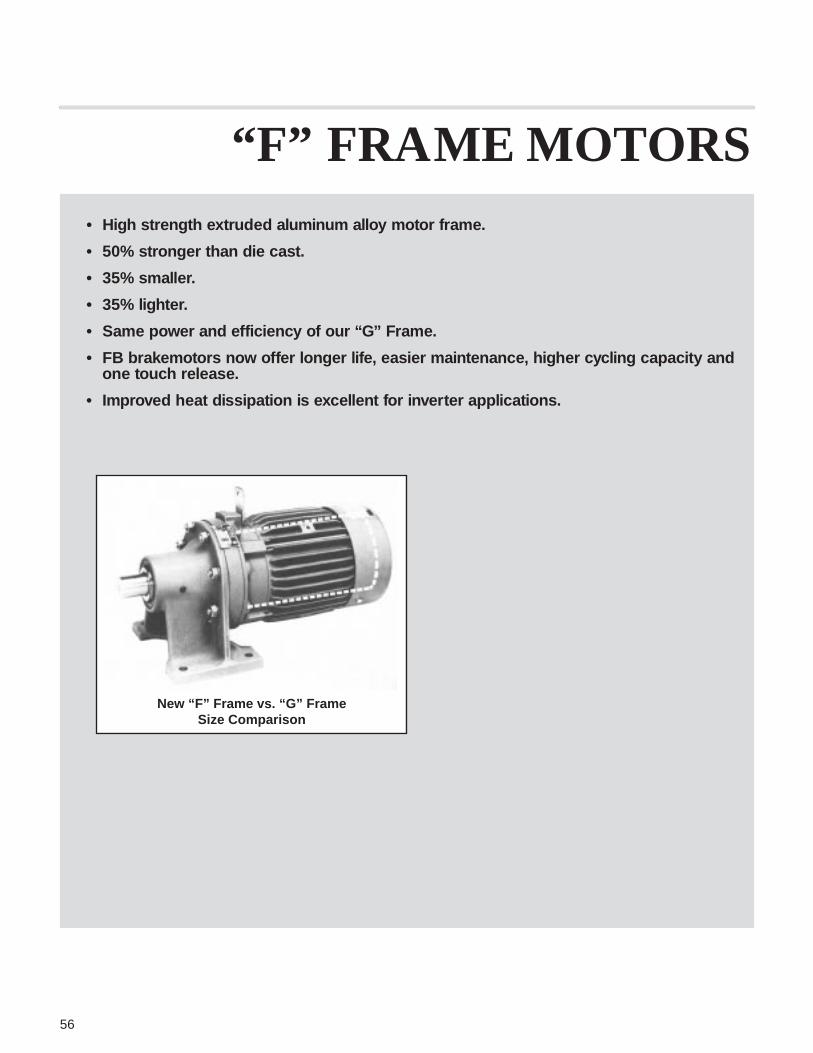
56
• High strength extruded aluminum alloy motor frame.
• 50% stronger than die cast.
• 35% smaller.
• 35% lighter.
• Same power and efficiency of our “G” Frame.
• FB brakemotors now offer longer life, easier maintenance, higher cycling capacity andone touch release.
• Improved heat dissipation is excellent for inverter applications.
“F” FRAME MOTORS
New “F” Frame vs. “G” FrameSize Comparison

57
ELECTRIC MOTORS & BRAKEMOTORS
Sumitomo Heavy Industries ElectricalDivision has been manufacturing varioustypes of motors since 1913. The motorused with the SM-CYCLO® gearmotor hasbeen manufactured since 1969 with wellover 3 million having been shippedthroughout the world.
Motor and Brake Motor Design Features
• Totally enclosed fan cooled• Squirrel cage rotor type• NEMA Design B or A• Designed for continuous duty• Ambient temperatures -15° through
40°C (5°-104°F)• Motor frames are made of Extruded
Aluminum.• Bearings are anti-friction type.• Insulation NEMA Class B
Special Motor Options• Brake Coil Voltage: 200 VDC from
rectifier. Standard Input Voltage is 208,230 and 460. Additional voltagesavailable. Please consult factory.
• Weatherproof: While our standardmotor is TEFC and may be usedoutdoors, when used in severeenvironments, weather protection maybe required.
Voltages
Standard motor and brake coil voltagesare 3 phase, 208/230/460V/575V 60 Hz.• See page 120 for single phase motor
characteristics.
Optional Voltages:• 190/380V at 50 Hz• For other available voltages please
consult factory.
• Insulation: NEMA Class FNEMA Class H
• Service Factor 1.15• Dust Proof• Chemical Duty• Low-Temperature Modification• Space Heater (115 or 230V)• High Slip Motors• Wash-Down• High Humidity
• Wound-Rotor Motor (crane usemotor)
• Star (Wye) — Delta Starting• Thermostat or Thermistor Protection• 6-Pole 1200 RPM Motor• Two-Speed Motor — Constant
Torque 1800/900 RPM• External Shoe Brakes for Large
Motors• Cast Iron Frames
HOW IT WORKSThe reducer portion has onlythree major moving parts1. The high speed input shaft with
integrally mounted eccentric camand roller assembly
2. The cycloid discs3. The slow speed shaft assemblyOperationAs the eccentric (high speed shaft)rotates, it rolls the cycloid discs aroundthe internal circumference of thestationary ring gear.
The movement of cycloid disc istransmitted to the slow speed shaft bythe projection of pins through the boresof the discs.A two disc system is used to increasetorque capacities and offer anexceptionally smooth vibrationless drive.There is one less tooth per cycloid discthan there are pins in the fixed ring gear,which results in reduction ratios beingequal to the number of teeth in each disc.
(NOTE: On some ratios, there are twoless teeth per cycloid disc than thereare pins in the fixed ring gear.)The movement of cycloid disc istransmitted to the slow speed shaft bythe projection of pins through the boresof the discs.

58
STANDARD MOTOR CHARACTERISTICS
Motor CharacteristicsThe SM-CYCLO® gearmotors full loadratings and amperage can be foundbelow in table M-1. These ratings arebased on the motors design values. Ifadditional information is requiredplease consult factory.
Effi- Power InertiaFrame Torque Break- ciency Factor Code WR2HP Size rpm in. lb. 230V 460V 208V 230V 460V Starting down % % Letter* lb. ft2
1/8** F-63S 1730 4.50 0.7 0.35 0.65 2.8 1.4 326 329 64.0 59.5 K 0.0077
1/4 F-63M 1730 9.06 1.1 0.60 1.1 5.2 2.6 300 293 69.8 65.2 K 0.0119
1/3 F-63M 1710 12.3 1.3 0.65 1.3 5.2 2.6 232 232 70.8 72.0 G 0.0119
1/2 F-71M 1740 18.3 2.1 1.1 2.0 9.8 4.9 295 280 71.9 65.1 J 0.0154
3/4 F-80S 1730 27.4 2.5 1.2 2.5 12.3 6.2 266 245 76.9 73.0 H 0.0227
1 F-80 1750 36.0 3.4 1.7 3.4 17.6 8.8 269 303 77.2 72.3 H 0.0285
1.5 F-90S 1730 54.7 4.7 2.4 4.7 28.6 14.3 273 281 80.3 74.1 J 0.0451
2 F-90L 1740 72.5 6.1 3.0 6.2 36.8 18.4 263 270 82.3 75.6 J 0.0504
3 F-100L 1730 109 8.5 4.3 8.7 54.8 27.4 277 266 84.4 77.2 J 0.0789
5 F-112M 1730 183 13.1 6.6 13.7 91.5 45.8 308 279 86.3 82.4 J 0.201
7.5 F-132S 1710 277 18.1 9.0 20.1 120 60 230 223 86.9 88.1 H 0.271
10 F-132M 1740 361 23.6 11.8 26.4 147 73.5 212 214 89.6 88.9 G 0.635
15 F-160M 1740 542 34.3 17.2 38.2 231 115 248 221 90.4 89.0 G 0.891
20 G-160L 1740 725 45.8 22.9 51 272 136 222 220 91.6 89.9 F 2.13
25 G-180M 1770 891 57 28.4 63 343 171 199 235 92.6 88.2 F 5.34
30 G-180M 1760 1075 68 34.2 77 388 194 192 226 91.5 88.1 F 5.34
40 F-180L 1750 1442 93 46.3 100 704 352 310 274 92.2 88.3 H 5.93
50 F-200L 1740 1812 114 57 124 904 452 340 286 92.1 88.5 J 7.30
60 F-200L 1740 2175 138 69 150 1078 539 340 279 92.5 88.4 J 8.13
75 F-225S 1750 2703 167 83 183 1257 629 277 282 92.2 89.8 H 16.0
Table M-1 — 230/460 Volt, Synchronous Speed 1800 rpm, 60 Hz, Continuous Duty, TEFC
Full Load Full Load CurrentAmperage
Starting CurrentAmperage
Torque% of F.L.
Effi- Power InertiaFrame Torque Break ciency Factor Code WR2HPSize rpm in. lb. 230V 460V 230V 460V Starting down % % Letter* lb. ft2
20 G-180M 1160 1087 52 25.9 327 163 263 254 91.3 79.5 H 7.53
25 F-180L 1160 1359 59 29.7 412 206 261 286 90.9 86.0 H 8.60
30 F-180L 1170 1617 71 35.6 506 253 273 297 92.4 83.8 H 8.60
40 F-200L 1180 2138 95 47.6 703 352 318 305 93.1 85.0 H 11.3
50 F-200L 1170 2695 117 59 923 462 348 327 92.9 85.1 J 14.2
60 F-225S 1170 3234 140 70 963 481 290 267 92.6 86.9 H 23.7
75 F-250S 1160 4078 170 85 1141 570 289 259 93.0 87.2 G 27.9
Table B Synchronous Speed 1200 rpm, 60 Hz, Continuous DutyFull Load Full Load
Current Amp.Starting
Current Amp.Torque
% of F.L.
*Code letter shown is for 230V or 460V operation. Consult factory for other voltages. **1⁄8 HP is TENV
*Code letter shown is for 230V or 460V operation. Consult factory for other voltages.

59
Effi- Power InertiaHP Frame Torque Break- ciency Factor Code WR2
Size rpm in. lb. 575V 575V Starting down % % Letter* lb. ft2
1/8 F-63S 1720 4.58 0.28 1.3 376 391 65.2 54.1 L 0.0077
1/4 F-63M 1720 9.17 0.48 2.2 316 340 69.4 60.3 K 0.0119
1/3 F-63M 1710 12.8 0.52 2.2 250 270 71.3 67.7 H 0.0119
1/2 F-71M 1700 18.6 0.79 3.7 309 300 75.8 67.4 H 0.0154
3/4 F-80S 1720 27.5 0.94 4.5 247 227 77.4 75.9 G 0.0227
1 F-80M 1680 37.5 1.3 6.6 252 256 78.1 74.9 H 0.0285
1.5 F-90S 1720 55.1 1.8 11.5 280 294 81.5 75.0 J 0.0451
2 F-90L 1720 73.3 2.3 14.3 264 268 82.5 77.8 H 0.0504
3 F-100L 1710 111 3.3 21.3 269 264 84.2 79.5 J 0.0789
5 F-112M 1730 182 5.2 39.5 268 271 86.6 82.7 J 0.201
7.5 F-132S 1720 278 7.7 62 298 263 87.1 82.6 K 0.271
10 F-132M 1740 362 9.7 74 275 266 89.9 86.4 J 0.635
15 F-160M 1750 540 14.1 113 305 275 90.4 86.6 J 0.889
20 G-160L 1770 713 18.7 147 310 304 92.6 86.9 J 2.13
25 G-180M 1780 886 23.7 190 281 332 93.2 84.2 J 5.34
30 G-180M 1780 1063 27.6 190 238 278 93.2 85.8 G 5.34
40 F-180L 1780 1417 37.1 282 311 275 92.1 88.2 H 5.93
50 F-200L 1780 1772 45.0 355 333 281 93.0 88.9 H 7.30
Table M-1 — 575 Volt, Synchronous Speed 1800 rpm, 60 Hz, Continuous Duty
Full Load Full LoadCurrent Amp.
StartingCurrent Amp.
Torque% of F.L.
*Code letter shown is for 230V or 460V operation. Consult factory for other voltages.
Standard Wiring Diagram — 208, 230/460
Illustrated below are the wiring diagrams for our standard motor, for additional information please refer to motor name plate. Due tochanges in design features, this diagram may not always agree with that on the motor. If different, the motor diagram found insidethe conduit box cover is correct.
Y-Connected (5 HP and smaller) Delta-Connected (7.5 HP and larger)
LINE 208/230V 60 Hz LINE 460V 60 Hz LINE 208/230V 60 Hz LINE 460V 60 Hz

60
ASSEMBLY OF STANDARD MOTORS
A cut-a-way drawing of the standard motor is shown in Fig. M-2.
Brakemotors are shown in Fig. M-3 on page 64.
Figure M-2 Standard Motor Part No. Description (M-2)
1 Bearing Cover
2 Bearing
3 Bolt
4 Fan*
5 Fan Cover
6 End Bracket
7 Bolt
8 Bolt
9 Internal Fan
10 Hub
11 Short Circuit Ring
12 Rotor Core
13 Stationary Core
14 Stator Frame
15 Stator Winding
16 Bolt
17 Eye Bolt
18 Cyclo Flange Bracket
19 Bearing
20 Slinger
21 Motor Shaft
22 Conduit Box
23 Bearing Cover
24 Oil Seal
25 Bearing Sleeve
*No Fan 1⁄8 HP, F-63S frame.
Frame Size F-63M thru F-160M
Frame Size G-160L and Larger

61
RECTIFIER DATA
RECTIFIER P.N.BRAKE MOTOR VOLTAGE SINGLE VOLTAGETYPE (HP X P) (V) (SEE NOTE BELOW)
180 ~ 250 05F-2FBFB-01A 1/8 x 4
*340 ~ 460 05F-4FB
1/4 x 4 180 ~ 250 05F-2FBFB-02A
1/3 x 4 *340 ~ 460 05F-45FB
180 ~ 250 05F-2FBFB-05A 1/2 x 4
*330 ~ 460 05F-4FB
3/4 x 4 180 ~ 250 05F-2FBFB-1A
1 x 4 *251 ~ 460 05F-4FB
1.5 x 4 180 ~ 250 10F-2FBFB-2A
2 x 4 *251 ~ 460 05F-4FB
180 ~ 250 10F-2FBFB-3A 3 x 4
*340 ~ 460 05F-4FB
180 ~ 240 10F-2FBFB-5A 5 x 4
*340 ~ 460 05F-45B
FB-8A 7.5 x 4 180 ~ 460 05F-4FB
FB-10A 10 x 4 190 ~ 460 15F-4FB
FB-15A 15 x 4 190 ~ 460 15F-4FB
CMB-20 20 x 4 180 ~ 460 SB25F-3HS
*OptionNOTE: Dual Voltage Rectifier P.N. 25FW-4FB is now standard for all FB brakes.
The voltage range is 190 ~ 460 V.Single Voltage Rectifiers must be used with proper voltage brake coil.

% Motor Torque TypicalCondition Rating Application Remarks
Rapid Brake Action 100% Machine ToolCutter andTable Transfer
Frequent Start/ 100% Conveyor Drive Fast Brake ActionStop May Be Required
Rapid Braking Over 150% Crane, Hoist Wiringand Fail Safe Winch, Gate, Connection for
Lifting Fast Brake ActionRequired
Rapid Deceleration Over 150% Centrifuge Driveof High Inertia Textile
62
BRAKEMOTOR CHARACTERISTICS
The brakemotor on SM-CYCLO®
gearmotors operates on a D.C. currentsupplied by a dual voltage rectifiermounted on the motor conduit box.The standard brake input voltage is208V OR 230V OR 460V at 60 Hz. (Forother available voltages see page 57.)Our standard brakemotor when usedfor outdoor installations must beprotected with some type of covering.Such coverings are available from thefactory, please inquire when ordering.Note: While the brake torque can befield adjusted within a limited range, ifyou require larger or smaller braketorque than those listed, please advisethe factory when ordering.
Table B-1 Required Brake Response Action
TYPE BRAKETorqueft. lb.
Brake Delay Time (sec) Coil CurrentAC AmerageInertia
WR2 Normal FastHP Motor Brake lb.ft 2 Braking Braking
Frame Model Std. Max. Action Action 230V 460V 208V
1/8 F-63S FB-01A 0.7 1.0 0.0083 0.15 ~ 0.2 0.015 ~ 0.02 0.06 0.04 0.06
1/4 F-63M FB-02A 1.4 2.9 0.0131 0.15 ~ 0.2 0.015 ~ 0.02 0.1 0.06 0.1
1/3 F-63M FB-02A 1.4 2.9 0.0131 0.15 ~ 0.2 0.015 ~ 0.02 0.1 0.06 0.1
1/2 F-71M FB-05A 2.9 2.9 0.016 0.1 ~ 0.15 0.01 ~ 0.015 0.1 0.06 0.1
3/4 F-80S FB-1A 5.8 7.7 0.0267 0.2 ~ 0.3 0.01 ~ 0.02 0.1 0.1 0.1
1 F-80M FB-1A 5.8 7.7 0.0308 0.2 ~ 0.3 0.01 ~ 0.02 0.1 0.1 0.1
1.5 F-90S FB-2A 11 14 0.0510 0.2 ~ 0.3 0.01 ~ 0.02 0.3 0.2 0.3
2 F-90L FB-2A 11 14 0.0564 0.2 ~ 0.3 0.01 ~ 0.02 0.3 0.2 0.3
3 F-100L FB-3A 16 21 0.0884 0.3 ~ 0.4 0.02 ~ 0.03 0.4 0.2 0.4
5 F-112M FB-5A 27 36 0.239 0.4 ~ 0.5 0.02 ~ 0.03 0.5 0.3 0.4
7.5 F-132S FB-8A 40 53 0.309 0.3 ~ 0.4 0.02 ~ 0.03 0.5 0.3 0.4
10 F-132M FB-10A 54 72 0.736 0.7 ~ 0.8 0.04 ~ 0.05 0.8 0.5 0.7
15 F-160M FB-15A 80 80 0.991 0.5 ~ 0.6 0.04 ~ 0.05 0.8 0.5 0.7
20 G-160L CMB-20 72 80 3.150 0.6 ~ 0.8 0.1 ~ 0.15 1.7 1.9 1.5

63
Typical Brakemotor WiringIllustrated below is a typical brakemotor wiring schematic. Note the rectifier shown is supplied in the motor conduit box. Due tochanges in design features, this diagram may not always agree with that on the motor. If different, the motor diagram found insidethe conduit box cover is correct.Y Connected - (11⁄2 HP and smaller) Delta Connected - (2 HP thru 15 HP)
• New dual voltage rectifier can be wired for 230V or 460V supply.• Solid lines show the wiring connections for standard brake action.• For fast brake action connect terminals as indicated by dotted lines. Add an additional contactor, and varistor VR from Table BV-1
below. Do not connect terminal N on brake coil to terminal 3 on rectifier for fast brake action. For 460V fast action braking do notconnect terminal N on brake coil to terminal 2 on rectifier.
Table BV-1: Varistors for Fast Braking Action
OPERATING VOLTAGE 208 V / 230 V 460 V 575
Varistor Rated Voltage AC260 ~ 300 V AC510 V AC604 V
Varistor Voltage 430 ~ 470 V 820 V .1000 V
FB-01A, 02A, 05A Over 0.2 W Over 0.4 W Over 0.4 W
FB-1A Over 0.4 W Over 0.6 W Over 0.6 W
FB-2A, 3A, 5A, 8A Over 0.6 W Over 1.5 W Over 1.5 W
FB-10A, 15A Over 1 W Over 1.5 W Over 1.5 W
VaristorRated
Wattage
* Option
• Please refer to page 61 for rectifier data.

64
ASSEMBLY OF BRAKEMOTORS
Figure M-3 Brakemotor Type FB-01, -02, -05Part No. Description1 Stationary Core2 Restraining Bolt3 Pressure Spring4 Auxiliary Spring5 Brake Lining
10 Brake Cover12 Pin14 Armature Plate15 Solenoid Coil16 Bearing17 Motor Shaft24 Bushing25 Retaining Ring26 Fan (CMB-T01 is w/o Fan)27 Plate28 Adjusting Nut
Type FB-1APart No. Description1 Stationary Core2 Brake Release Support3 Shifting Pin4 Spacer5 GAP Adjusting Sleeve6 Brake Release Lever7 Restraining Bolt8 Brake Lining9 Leaf Spring
10 Hub11 Retaining Ring12 Fan Cover13 Fan Set Screw14 Fan15 Fixed Plate16 Noise Shield17 Brake Shoe18 Armature Plate19 Pressure Spring20 Solenoid Coil21 Fan Side Motor Bearing22 Motor Shaft
Type FB-2A thru 15APart No. Description1 Stationary Core2 Brake Release Support3 Stud Bolt4 GAP Adjusting Sleeve5 Shifting Pin6 Brake Release Lever7 Spring Washer8 Nut9 Brake Lining
10 Hub11 Retaining Ring12 Fan Cover13 Fan Set Screw14 Fan15 Brake Shoe16 Armature Plate17 Pressure Spring18 Solenoid Coil19 Fan Side Motor Bearing20 Motor Shaft21 Bearing Cover
A
B
C

65
Part No. Description1 Stationary Core2 Restraining Bolt3 Pressure Spring4 Auxiliary Spring5 Brake Lining7 Restraining Nut8 Adjusting Bolt (Not Supplied)9 Motor
10 Brake Cover11 Bolt12 Pin13 Brake Wheel14 Armature Plate15 Solenoid Coil16 Bearing17 Motor Shaft18 Roller19 Plug20 Dust Proof Seal21 Shifting Plate22 Nut23 Conduit Box
Figure M-4 Type CMB-20. Table 6 Main Parts – C
NOTE: For single voltage brakemotor 208V, 230V, 460V, 575V, or other special voltages pleaserefer to the motor mounted connection diagram or refer to factory.
OLR: Overload Relay or Thermal RelayMC: Electromagnetic Contactor
R: Resistor (2 watt, 200~300Ω)
Wiring Diagram for CMB-20
NORMAL BRAKE ACTION(1) LOW VOLTAGE 200 ~ 230V
(2) HIGH VOLTAGE 400 ~ 460V (2) HIGH VOLTAGE 400 ~ 460V
FAST BRAKE ACTION(1) LOW VOLTAGE 200 ~ 230V
D

Y A
66
NOMENCLATURE
NOTE: See pages 6 through 8 for complete nomenclature information.
INPUT POWER – FOR INTEGRAL MOTOR UNITS ONLY
4 SYMBOL 01 02 03 05 08 1 1H 2 3 5 8 10 15 20 25 30 40 50POLE HP 1/8 1/4 1/3 1/2 3/4 1 1.5 2 3 5 7.5 10 15 20 25 30 40 50
Kilowatt 0.1 0.2 0.25 0.4 0.55 0.75 1.1 1.5 2.2 3.7 5.5 7.5 11 15 18.5 22 30 37
6 SYMBOL 206 256 306 406 506POLE HP 20 25 30 40 50
60 75 10060 75 100
45 55 75
606 756 100660 75 100
C N H M 05 4085 17
PRODUCT
C CYCLO
O/P DIRECTION
N UNIVERSAL
H HORIZONTAL
V VERTICAL DN
W VERTICAL UP
MOUNTING
H FOOT
F FLANGE
V FLANGE
INPUT CONNECTION
M INTEGRAL MOTOR
J C-FACE ADAPT.
FREE SHAFT
X QUILL AND ADAPT.
SEE TABLE 2, PG. 7
MODIFICATION
S SPECIAL
STD MODEL
FRAME SIZE
SEE LISTING
INSIDE BACK
COVER OR
PAGE 12
SHAFT SPEC
Y INCH STD.
G METRIC DIN
METRIC JIS
AGMA CLASS
A AGMA I
B AGMA II
C AGMA III
SPECIFICATION SUFFIX
TL TORQUE LIMITER
SB SHOVEL BASE
AV AF MOTOR
SG SINGLE PH. MOTOR
SEE TABLE 3, PG. 7
BRAKE
B W/BRAKE
NO BRAKE
RATIO

67
HOW TO SELECT FRAME SIZE & MODEL
Step 1Refer to Selection Procedure at thebottom of this page.
Step 2 Determine type of gearmotor requiredfor your particular application: withbrake or without brake horizontal orvertical. Mounting position must alsobe determined. Refer to page 60 forStandard Assemblies.
Step 3Determine the Load Classification forthe Application from AGMA LoadClassifications tables on pages 68 and69. If the application is not listed referto the Factory.
Step 4Select unit size for horsepower andoutput RPM. Refer to Rating tables onpages 70 through 107 and determineframe size.
Step 5Check overhung load when drive is notdirect (i.e., coupled to the drivenmachine). When a chain, gear or beltdriven machine is connected to agearmotor output shaft, calculate theoverhung load by using the AllowableOverhung Load tables, pages 124through 126.
Step 6Refer to pages 108 through 119 and122 through 123 for required outlinedimensions.The following is an example of propergearmotor selection
SELECT EXAMPLEConditions:1. Driven Machine — Belt Conveyor
Drive2. Duty Cycle — 24 hours a day with
uniform loading3. Input HP — 5 HP4. Motor Specs — 3 phase, 60 Hertz
230/460 volts, totally enclosed5. Output speed — 20 RPM6. Mounting Position — Horizontal
base-mounted reducer. 9˝ pitchdiameter sprocket mounted on theoutput shaft. Center line of the loadis 1.50˝ from the collar surface.
Selection:1. Load Classification is established as
Class II from AGMA LoadClassification Table on pages 64 and65.
2. Class II Selection Table is catalogedon page 89. In the 5 HP columnopposite 20 RPM output speed,Frame Size M4175-B is listed.
3. To check the overhung load capacity,refer to the rating table on pages 124and 125. For Frame Size 4175 at 20RPM output speed, the overhungload capacity is 5920 pounds.
Next, following the example on page 124use the formula to determine the actualoverhung load.Overhung = 126,000 x HP x Cf x Lf x Sf
Load D x N
126,000 x 5 x 1.0 x 0.96 x 1.3 = 4368 lbs.9.0 x 20Since the overhung load capacity of5920 pounds is greater than the actualoverhung load of 4368 pounds, thisapplication is satisfactory.
4. Correct nomenclature for this unitwould then be CHM5-4175YB @20 RPM output (refer to page 66).
Selection ProcedureThe following data are required to permitproper selection of the SM-CYCLO®
gearmotor. Selection procedure stepsare covered in detail above and on page12 together with selection examples:1. Application2. Determination of Load Classification3. Output RPM4. Required HP5. Mounting position and special
modifications, if any.
AGMA Load ClassificationsIn order to facilitate selection,SM-CYCLO® gearmotors are rated byAGMA load classifications. Values formost applications are listed on pages 68and 69. For unlisted applications or forload conditions heavier than classified(such as 24-hour heavy shock loads)refer to the Factory.
Service FactorsTime of operation and frequency andseverity of shock must be determined inorder to select the proper SM-CYCLO®
gearmotor for a specific application. Toassist in the selection process, AGMAhas defined three standard ServiceFactors. However, the Service Factorsto be used for the selection of theSM-CYCLO® gearmotors differ from thestandard Service Factors of AGMA asshown in the table at right.The SM-CYCLO® gearmotor ServiceFactors are smaller than those of theAGMA because AGMA Service Factors
are determined on the basis of thestrength of gears in the conventionalhelical or worm gear speed reducers.The reducer portion of the SM-CYCLO®
gearmotor has higher overload capacitythan conventional helical or worm gearspeed reducers as a result of the toothshape, the greater number of teeth incontact, and the high material quality ofthe components.
GEARMOTOR CLASSIFICATION TABLE
GEARMOTOR CLASS
UNIFORM MODERATE HEAVYDURATION OF SERVICE LOAD SHOCK LOAD SHOCK LOAD
Intermittent 3 Hr. per day Class I Class I Class II
Up to 10 Hr. per day Class I Class II Class III
24 Hr. per day Class II Class III —
Class I — SM-CYCLO® Drive S.F. 1.0 (AGMA Equiv. S.F. 1.0)
Class II — SM-CYCLO® Drive S.F. 1.3 (AGMA Equiv. S.F. 1.4)
Class III — SM-CYCLO® Drive S.F. 1.6 (AGMA Equiv. S.F. 2.0)

Class
Application
AgitatorsPure Liquids I IILiquids and Solids II IILiquids – Variable
Density II IISemi-liquids –
Variable Density II II
BlowersCentrifugal I IILobe II IIVane I II
Brewing and DistillingBottling Machinery I IIBrew Kettles –
Continuous Duty – IICookers – Continuous
Duty – II
68
AGMA LOAD CLASSIFICATIONS
Class I For steady loads not exceeding normal motor rating,8 to 10 hours a day. Moderate shock loads where service isintermittent (SM-CYCLO Service Factor: 1.0; AGMA equivalentService Factor: 1.0).Class II For steady loads not exceeding normal motor ratingand 24 hours a day service. Moderate shock loads for 8 hours
a day (SM-CYCLO Service Factor: 1.3; AGMA equivalentService Factor: 1.4).Class III For moderate shock loads for 24 hours a day. Heavyshock loads for 8 hours a day (SM-CYCLO Service Factor: 1.6;AGMA equivalent Service Factor: 2.0).
Class
Application
Brewing & DistillingBottling Machinery I IIBrew Kettles, Cont.
Duty – IICan Filling Machines I IICookers–Cont. Duty – IIMash Tubs–Cont. Duty – IIScale Hoppers–
Frequent Starts II II
Clay Working IndustryBrick Press III IIIBriquette Machines III IIIClay Working
Machinery II IIPug Mills II II
Distilling (See Brewing)
DredgesCable Reels II –Conveyors II IICutter Head Drives III IIIJig Drives III IIIManeuvering Winches II –Pumps II IIScreen Drives III IIIStackers II IIUtility Winches II –
Food IndustryBeet Slicers II IIBottlings, Can
Filling Mach. I IICereal Cookers I IIDough Mixers II IIMeat Grinders II II
Class
Application
Lumber IndustryBarkers–
Spindle Feed II IIIBarkers–
Main Drive III IIICarriage DriveConveyors
Burner II IIIMain or Heavy Duty II IIIMain Log III IIIRe-Saw
Merry-Go-Round II IIISlab III IIITransfer II III
Chains–Floor II IIIChains–Green II IIICut-Off Saws–Chain II IIICut-Off Saws–Drag II IIIDebarking Drums III IIIFeeds–Edger II IIIFeeds–Gang III IIIFeeds–Trimmer II IIILog Deck III IIILog Hauls–Incline,
Well Type III IIILog Turning Devices III IIIPlaner Feed II IIIPlaner Tilting Hoists II IIIRolls–Live–Off
Bearing–Roll Cases III IIISorting Table II IIITipple Hoist II IIITransfers–Chain II IIITransfers–Craneway II IIITray Drives II III
Oil IndustryChillers II II
Class
Application
Oil Well PumpingParaffin Filter Press II IIRotary Kilns II II
Paper MillsAgitators (Mixers) II IIBarker–Auxiliaries–
Hyd. – IIIBarker, Mechanical – IIIBarking Drum – IIIBeater & Pulper – IIBleacher – IICalenders – IICalenders–Super – IIConverting Mach.–
Except Cutters–Platers – II
Conveyors – IICouch – IICutters, Platers – IIICylinders _ IIDryers – IIFelt Stretchers – IIFelt Whippers – IIIJordans – IILog Haul – IIIPresses – IIPulp Machine Reels – IIStock Chests – IISuction Rolls – IIWashers & Thickeners – II
Winders – II
Rubber IndustryMixer III IIIRubber Calender II IIRubber Mill (2 or more) II II
Sheeter II II
Class
Application
Tire Building MachinesTire, Tube Press
OpenersTubers & Stainers II II
Sewage DisposalAeratorsBar Screens I IIChemical Feeders I IICollectors I IIDewatering Screens II IIGrit Collectors I IIScum Breakers II IISlow or Rapid Mixers II IISludge Collectors I IIThickeners II IIVacuum Filters II II
Textile IndustryBatchers II IICalenders II IICard Machines II IICloth Finishing Machines
Calenders, Dryers,Pads, Tenters, Washers) II II
Dry Cans II IIDyeing Machinery II IIKnitting MachineryLooms, Mangles,
Nappers II IIRange DrivesSoapers, Spinners II IITenter Frames II IIWinders II IIYarn Preparatory
Machinery (Cards, Spinners,Slashers) II II
Up to10 Hr.
perday
24Hr.perday
Up to10 Hr.
perday
24Hr.perday
Up to10 Hr.
perday
24Hr.perday
Up to10 Hr.
perday
24Hr.perday
Up to10 Hr.
perday
24Hr.perday
Class
Application
Mash Tubs –Continuous Duty – II
Scale HopperFrequent Starts II II
Can Filling Machines I II
Cane Knives II II
Car Dumpers III –
Car Pullers –Intermittent Duty I –
Clarifiers I II
Up to10 Hr.
perday
24Hr.perday
Class
Application
Classifiers II IIClay Working
MachineryBrick Press III IIIBriquette Machine III IIIClay Working
Machinery II IIPug Mill II II
CompressorsCentrifugal I IILobe II IIReciprocating
Multi-Cylinder II IISingle Cylinder III III
Conveyors – UniformlyLoaded or FedApron I II
Up to10 Hr.
perday
24Hr.perday
Class
Application
Assembly I IIBelt I IIBucket I IIChain I IIFlight I IIOven I IIScrew I II
Conveyors – Heavy DutyNot Uniformly Fed
Apron II IIAssembly II IIBelt II IIBucket II IIChain II IIFlight II IILive Roll (Package) I IIOven II IIReciprocating III III
Up to10 Hr.
perday
24Hr.perday
LOAD CLASSIFICATION LISTED BY APPLICATION
Refer to Factory
LOAD CLASSIFICATION LISTED BY INDUSTRY
Refer to Factory
Refer to Factory
Refer to Factory
Refer to Factory
Refer to Factory
Refer to Factory

Class
Application
Mills, Rotary TypeBall III IIICement KilnsDryers & Coolers II IIKilns II IIPebble III IIIRod III IIITumbling Barrels III III
MixersConcrete Mixers,
Continuous II IIConcrete Mixers,
Intermittent I –Constant Density I IIVariable Density II II
Oil IndustryChillers II IIOil Well PumpingParaffin Filter Press II IIRotary Kilns II II
Paper MillsAeratorsAgitators (Mixers) II IIBarker Auxiliaries,
Hydraulic – IIIBarker, Mechanical – IIIBarking Drum – IIIBeater & Pulper – IIBleacher – IICalenders – IICalenders – Super – IIConverting Machines,
except Cutters, Platers – II
Conveyors – IIConveyors, Log – IIICouch – IICutters, Platers – IIICylinders – IIDryers – IIFelt Stretcher – IIFelt Whipper – IIIJordans – IIPresses – IIPulp Machines, Reel – IIStock Chests – IISuction Roll – IIWashers and
Thickeners – IIWinders – II
Printing Presses I II
PullersBarge Haul III III
PumpsCentrifugal I IIProportioning II IIReciprocating
Single Acting3 or more Cylinders II II
Double Acting2 or more Cylinders II II
Single Acting1 or 2 Cylinders
Double ActingSingle Cylinder
24Hr.perday
Up to10 Hr.
perday
69
LOAD CLASSIFICATION LISTED BY APPLICATION
Class
Application
Screw II IIShaker III III
Cranes and HoistsMain Hoists III III
Heavy Duty III IIIMedium Duty II II
Reversing II IISkip Hoists II IITrolley Drive II IIBridge Drive II II
CrushersOre III IIIStone III III
DredgesCable Reels II –Conveyors II IICutter Head Drives III IIIJig Drives III IIIManeuvering Winches II –Pumps II IIScreen Drive III IIIStackers II IIUtility Winches II –
ElevatorsBucket – Uniform Load I IIBucket – Heavy Load II IIBucket – Continous I IICentrifugal Discharge I IIEscalators I IIFreight I IIGravity Discharge I IIMan LiftsPassenger
Service – Hand Lift III –
FansCentrifugal II IICooling Towers
Induced Draft II IIForced DraftInduced Draft II IILarge (Mine, etc.) II IILarge Industrial II IILight (Small Diameter) I II
FeedersApron II IIBelt II IIDisc I IIReciprocating III IIIScrew II II
Food IndustryBeet Slicer II IICereal Cooker I IIDough Mixer II IIMeat Grinders II II
Generators –(Not Welding) I II
Hammer Mills III III
Laundry WashersReversing II II
Laundry Tumblers II II
24Hr.perday
Class
Application
Line ShaftsHeavy Shock Load III IIIModerate
Shock Load II IIUniform Load I II
Lumber IndustryBarkers – Spindle FeedBarkers – Main DriveCarriage DriveConveyors – Burner II IIIConveyors – Main or
Heavy Duty II IIIConveyors – Main Log III IIIConveyors –
Merry-Go-Round II IIIConveyors – Slab III IIIConveyors – Transfer II IIIConveyors – Waste II IIChains – Floor II IIIChains – Green II IIICut-Off Saws – Chain II IIICut-Off Saws – Drag II IIIDebarking Drums III IIIFeeds – Edger II IIIFeeds – Gang III IIIFeeds – Trimmer II IIILog Deck III IIILog Hauls – Incline
Well Type III IIILog Turning Devices III IIIPlaner Feed II IIIPlaner Tilting Hoists II IIIRolls – Live – Off Brg.
– Roll Cases III IIISorting Table II IIITipple Hoist II IIITransfers – Chain II IIITransfers – Craneway II IIITray Drives II IIIVeneer Lathe Drives
Machine ToolsBending Roll II IINotching Press –
Belt DrivenPlate Planer III IIIPunch Press –
Gear Driven III IIITapping Machines III IIIOther Machine Tools
Main Drives II IIAuxiliary Drives I II
Metal MillsBridle Roll Drives III IIIDraw Bench – Carriage III IIIDraw Bench –
Main Drive III IIIForming Machines III IIIPinch Dryer & Scrubber
Rolls, ReversingSlitters II IITable Conveyors
Non-Reversing II IIIReversing – III
Winding Reels – Strip – IIIWire Drawing &
Flattening Machine II IIIWire Winding Machine II II
Up to10 Hr.
perday
24Hr.perday
Up to10 Hr.
perday
Class
Application
Rotary – Gear Type I II– Lobe, Vane I II
Rubber IndustryMixer III IIIRubber Calender II IIRubber Mill (2 or more) II IISheeter II IITire Building MachinesTire & Tube Press
OpenersTubers and Strainers II II
Sewage Disposal EquipmentAeratorsBar Screens I IIChemical Feeders I IICollectors, Circuline
or Straightline I IIDewatering Screens II IIGrit Collectors I IIScum Breakers II IISlow or Rapid Mixers II IISludge Collectors I IIThickeners II IIVacuum Filters II II
ScreensAir Washing I IIRotary – Stone
or Gravel II IITraveling Water
Intake I II
Slab Pushers II IISteering Gear II IIStokers I II
Textile IndustryBatchers II IICalenders II IICard Machines II IICloth Finishing Machines
(Washers, Pads,Tenters)(Dryers, Calenders, etc.) II II
Dry Cans II IIDryers II IIDyeing Machinery II IIKnitting Machines
(Looms, etc.)Looms II IIMangles II IINappers II IIPads II IIRange DrivesSlashers II IISoapers II IISpinners II IITeneter Frames II IIWashers II IIWinders (Other
than Batchers) II IIYarn Preparatory
Machines (Cards,Spinners, Slashers,etc.) II II
Windlass II II
Up to10 Hr.
perday
24Hr.perday
Refer to Factory
Refer to Factory
Refer to Factory
Refer to Factory
Refer to Factory
Refer to Factory
Refer to Factory
Refer to Factory
Refer to FactoryRefer to FactoryRefer to Factory
Refer to Factory
Refer to Factory
Refer to Factory
Refer to Factory
Refer to Factory
Refer to Factory

70
RATING TABLE
1/8 HORSEPOWER
CLASS I SM-CYCLO S.F. = 1.0AGMA S.F. = 1.0
OUTPUTRPM RATIO
OUTPUTTORQUE(IN. LB.)
OVERHUNGLOAD(LB)
MODEL
UNIT WEIGHTTYPE (LBS)
H V
DIMENSIONTYPE (PAGE)
H V
292.00 6 25 280 4085-YA17 21 108 112
219.00 8 33 311 4085-YA
159.00 11 46 207 4075-YA
135.00 13 54 207 4075-YA
117.00 15 62 211 4075-YA
103.00 17 71 211 4075-YA16 18 108 112
83.30 21 87 211 4075-YA
70.00 25 104 211 4075-YA
60.30 29 121 211 4075-YA
50.00 35 146 211 4075-YA
40.70 43 179 211 4075-YA
34.30 51 212 397 4085-YA17 21 108 112
29.70 59 246 397 4085-YA
24.60 71 296 750 4090-YA33 31 108 112
20.10 87 362 750 4090-YA
17.20 102 390 750 4097-DA-YA 40 38 110 114
14.50 119 463 750 4090-YA 33 31 108 112
10.60 165 631 750 4097-DA-YA
10.10 174 666 750 4097-DA-YA
9.36 187 716 750 4097-DA-YA
8.33 210 804 750 4097-DA-YA 40 38 110 114
7.58 231 884 750 4097-DA-YA
6.78 258 987 750 4097-DA-YA
6.06 289 1110 750 4097-DA-YA
5.49 319 1220 1210 4105-DA-YA
4.55 385 1470 1210 4105-DA-YA44 40 110 114
4.02 435 1660 1210 4105-DA-YA
3.55 493 1890 1210 4105-DA-YA
2.94 595 2280 1940 4115-DB-YA
2.39 731 2800 1940 4115-DB-YA 74 72 110 114
2.08 841 3220 1940 4115-DB-YA

71
1/8 HORSEPOWER
CLASS II SM-CYCLO S.F. = 1.3AGMA S.F. = 1.4
OVERHUNGLOAD(LB)
MODEL
UNIT WEIGHTTYPE (LBS)
H V
DIMENSIONTYPE (PAGE)
H V
CLASS III SM-CYCLO S.F. = 1.6AGMA S.F. = 2.0
OVERHUNGLOAD(LB)
MODEL
UNIT WEIGHTTYPE (LBS)
H V
DIMENSIONTYPE (PAGE)
H V
280 4085-YB17 21 108 112
280 4085-YC17 21 108 112
311 4085-YB 311 4085-YC
207 4075-YB 207 4075-YC
207 4075-YB 207 4075-YC
211 4075-YB 211 4075-YC
211 4075-YB16 18 108 112
211 4075-YC 16 18 108 112
211 4075-YB 211 4075-YC
211 4075-YB 211 4075-YC
211 4075-YB 211 4075-YC
211 4075-YB 397 4085-YC17 21 108 112
397 4085-YB 397 4085-YC
397 4085-YB 17 21 108 112 750 4090-YC
397 4085-YB 750 4090-YC33 31 108 112
750 4095-YB33 31 108 112
750 4095-YC
750 4095-YB 750 4095-YC
750 4097-DA-YB 40 38 110 114 750 4097-DA-YC 40 38 110 114
750 4097-YB 33 31 108 112 750 4097-YA 33 31 108 112
750 4097-DA-YB 750 4097-DA-YC40 38 110 114
750 4097-DA-YB40 38 110 114
750 4097-DA-YC
750 4097-DA-YB 1210 4105-DA-YC
750 4097-DA-YB 1210 4105-DA-YC
1210 4105-DA-YB 1210 4105-DA-YC44 40 110 114
1210 4105-DA-YB 1210 4105-DA-YC
1210 4105-DA-YB 44 40 110 114 1210 4105-DA-YC
1210 4105-DA-YB 1210 4105-DA-YC
1210 4105-DA-YB 1940 4115-DB-YC
1940 4115-DB-YB 1940 4115-DB-YC
1940 4115-DB-YB 1940 4115-DB-YC74 72 110 114
1940 4115-DB-YB 74 72 110 114 1940 4115-DB-YC
1940 4115-DB-YB 1940 4115-DB-YC
1940 4115-DB-YB 1940 4115-DB-YC

72
RATING TABLE
1/4 HORSEPOWER
CLASS I SM-CYCLO S.F. = 1.0AGMA S.F. = 1.0
OUTPUTRPM RATIO
OUTPUTTORQUE(IN. LB.)
OVERHUNGLOAD(LB)
MODEL
UNIT WEIGHTTYPE (LBS)
H V
DIMENSIONTYPE (PAGE)
H V
292.00 6 50 280 4085-YA20 25 108 112
219.00 8 67 311 4085-YA
159.00 11 92 207 4075-YA
135.00 13 108 207 4075-YA
117.00 15 125 211 4075-YA 19 21 108 112
103.00 17 142 211 4075-YA
83.30 21 175 211 4075-YA
70.00 25 208 397 4085-YA
60.30 29 242 397 4085-YA20 25 108 112
50.00 35 291 397 4085-YA
40.70 43 358 397 4085-YA
34.30 51 425 750 4090-YA
29.70 59 491 750 4090-YA36 33 108 112
24.60 71 591 750 4095-YA
20.10 87 725 750 4095-YA
17.20 102* 781 750 4097-DA-YA 42 40 110 114
14.50 119 926 1210 4100-YA 43 38 108 112
10.60 165 1260 1210 4105-DA-YA
10.10 174 1330 1210 4105-DA-YA
9.36 187 1430 1210 4105-DA-YA
8.33 210 1610 1210 4105-DA-YA 47 42 110 114
7.58 231 1770 1210 4105-DA-YA
6.78 258 1970 1210 4105-DA-YA
6.06 289 2210 1210 4105-DA-YA
5.49 319 2440 1940 4115-DB-YA
4.55 385 2950 1940 4115-DB-YA
4.02 435 3330 1940 4115-DB-YA 77 75 110 114
3.55 493 3770 1940 4115-DB-YA
2.94 595 4550 1940 4115-DB-YA
2.39 731 5590 3310 4135-DC-YA115 110 110 114
2.08 841 6440 3310 4135-DC-YA
*These units supplied with 121:1 actual ratio.

73
1/4 HORSEPOWER
CLASS II SM-CYCLO S.F. = 1.3AGMA S.F. = 1.4
OVERHUNGLOAD(LB)
MODEL
UNIT WEIGHTTYPE (LBS)
H V
DIMENSIONTYPE (PAGE)
H V
CLASS III SM-CYCLO S.F. = 1.6AGMA S.F. = 2.0
OVERHUNGLOAD(LB)
MODEL
UNIT WEIGHTTYPE (LBS)
H V
DIMENSIONTYPE (PAGE)
H V
280 4085-YB20 25 108 112
280 4085-YC
311 4085-YB 311 4085-YC
207 4075-YB 353 4085-YC
207 4075-YB19 21 108 112
341 4085-YC 20 25 108 112
211 4075-YB 375 4085-YC
211 4075-YB 397 4085-YC
397 4085-YB 397 4085-YC
397 4985-YB20 25 108 112
750 4090-YC
397 4085-YB 750 4090-YC
397 4085-YB 750 4090-YC
750 4090-YB 750 4095-YC36 33 108 112
750 4095-YB 750 4095-YC
750 4095-YB 36 33 108 112 750 4095-YC
750 4097-YB 750 4097-YC
750 4097-YB 750 4097-YC
750 4097-DA-YB 42 40 110 114 1210 4105-DA-YC
1210 4105-YB 42 38 108 112 1210 4105-DA-YC 47 42 110 1141210 4105-DA-YB 1210 4105-DA-YC
1210 4105-DA-YB47 42 110 114
1210 4105-DA-YC
1210 4105-DA-YB 1940 4115-DB-YC
1210 4105-DA-YB 1940 4115-DB-YC
1940 4115-DB-YB 1940 4115-DB-YC
1940 4115-DB-YB 1940 4115-DB-YC 77 75 110 114
1940 4115-DB-YB77 75 110 114
1940 4115-DB-YC
1940 4115-DB-YB 1940 4115-DB-YC
1940 4115-DB-YB 1940 4115-DB-YC
1940 4115-DB-YB 3310 4135-DC-YC
1940 4115-DB-YB 3310 4135-DC-YC 115 110 110 114
3310 4135-DC-YB115 110 110 114
3310 4135-DC-YC
3310 4135-DC-YB 3600 4145-DB-YC 110 108 110 114
3310 4145-DB-YB 110 108 110 114

74
RATING TABLE
1/3 HORSEPOWER
CLASS I SM-CYCLO S.F. = 1.0AGMA S.F. = 1.0
OUTPUTRPM RATIO
OUTPUTTORQUE(IN. LB.)
OVERHUNGLOAD(LB)
MODEL
UNIT WEIGHTTYPE (LBS)
H V
DIMENSIONTYPE (PAGE)
H V
292.00 6 67 280 4085-YA20 25 108 112
219.00 8 89 311 4085-YA
159.00 11 122 207 4075-YA
135.00 13 144 207 4075-YA19 21 108 112
117.00 15 167 211 4075-YA
103.00 17 189 211 4075-YA
83.30 21 233 397 4085-YA
70.00 25 278 397 4085-YA20 25 108 112
60.30 29 322 397 4085-YA
50.00 35 389 397 4085-YA
40.70 43 478 750 4090-YA
34.30 51 567 750 4095-YA
29.70 59 655 750 4095-YA 36 33 108 112
24.60 71 789 750 4097-YA
20.10 87 966 750 4097-YA
17.20 102* 1040 750 4097-DA-YA 42 40 110 114
14.50 119 1230 1210 4105-YA 42 38 108 112
10.60 165 1680 1210 4105-DA-YA
10.10 174 1780 1210 4105-DA-YA47 42 110 114
9.36 187 1910 1210 4105-DA-YA
8.33 210 2140 1210 4105-DA-YA
7.58 231 2360 1940 4115-DB-YA
6.78 258 2630 1940 4115-DB-YA
6.06 289 2950 1940 4115-DB-YA
5.49 319 3260 1940 4115-DB-YA 77 75 110 114
4.55 385 3930 1940 4115-DB-YA
4.02 435 4440 1940 4115-DB-YA
3.55 493 5030 1940 4115-DB-YA
2.94 595 6070 3310 4135-DC-YA115 110 110 114
2.39 731 7460 3310 4135-DC-YA
2.08 841 8580 3600 4145-DB-YA 110 108 110 114
*These units supplied with 121:1 actual ratio.
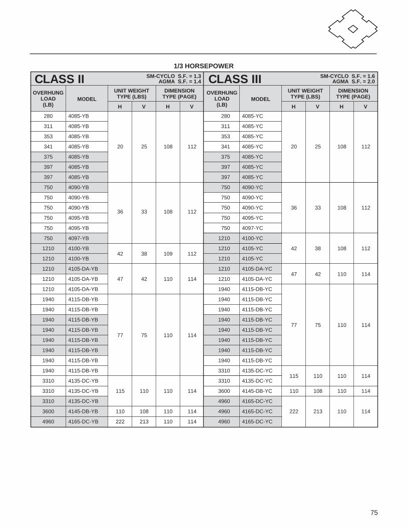
75
1/3 HORSEPOWER
CLASS II SM-CYCLO S.F. = 1.3AGMA S.F. = 1.4
OVERHUNGLOAD(LB)
MODEL
UNIT WEIGHTTYPE (LBS)
H V
DIMENSIONTYPE (PAGE)
H V
CLASS III SM-CYCLO S.F. = 1.6AGMA S.F. = 2.0
OVERHUNGLOAD(LB)
MODEL
UNIT WEIGHTTYPE (LBS)
H V
DIMENSIONTYPE (PAGE)
H V
280 4085-YB 280 4085-YC
311 4085-YB 311 4085-YC
353 4085-YB 353 4085-YC
341 4085-YB 20 25 108 112 341 4085-YC 20 25 108 112
375 4085-YB 375 4085-YC
397 4085-YB 397 4085-YC
397 4085-YB 397 4085-YC
750 4090-YB 750 4090-YC
750 4090-YB 750 4090-YC
750 4090-YB36 33 108 112
750 4090-YC 36 33 108 112
750 4095-YB 750 4095-YC
750 4095-YB 750 4097-YC
750 4097-YB 1210 4100-YC
1210 4100-YB42 38 109 112
1210 4105-YC 42 38 108 112
1210 4100-YB 1210 4105-YC
1210 4105-DA-YB 1210 4105-DA-YC47 42 110 114
1210 4105-DA-YB 47 42 110 114 1210 4105-DA-YC
1210 4105-DA-YB 1940 4115-DB-YC
1940 4115-DB-YB 1940 4115-DB-YC
1940 4115-DB-YB 1940 4115-DB-YC
1940 4115-DB-YB 1940 4115-DB-YC77 75 110 114
1940 4115-DB-YB77 75 110 114
1940 4115-DB-YC
1940 4115-DB-YB 1940 4115-DB-YC
1940 4115-DB-YB 1940 4115-DB-YC
1940 4115-DB-YB 1940 4115-DB-YC
1940 4115-DB-YB 3310 4135-DC-YC115 110 110 114
3310 4135-DC-YB 3310 4135-DC-YC
3310 4135-DC-YB 115 110 110 114 3600 4145-DB-YC 110 108 110 114
3310 4135-DC-YB 4960 4165-DC-YC
3600 4145-DB-YB 110 108 110 114 4960 4165-DC-YC 222 213 110 114
4960 4165-DC-YB 222 213 110 114 4960 4165-DC-YC

76
RATING TABLE
1/2 HORSEPOWER
CLASS I SM-CYCLO S.F. = 1.0AGMA S.F. = 1.0
OUTPUTRPM RATIO
OUTPUTTORQUE(IN. LB.)
OVERHUNGLOAD(LB)
MODEL
UNIT WEIGHTTYPE (LBS)
H V
DIMENSIONTYPE (PAGE)
H V
292.00 6 100 280 4085-YA
219.00 8 133 311 4085-YA
159.00 11 183 353 4085-YA
135.00 13 217 341 4085-YA 24 29 108 112
117.00 15 250 375 4085-YA
103.00 17 283 397 4085-YA
83.30 21 350 397 4085-YA
70.00 25 416 750 4090-YA
60.30 29 483 750 4090-YA
50.00 35 583 750 4090-YA39 36 108 112
40.70 43 716 750 4095-YA
34.30 51 849 750 4097-YA
29.70 59 983 750 4097-YA
24.60 71 1180 1210 4105-YA46 40 108 112
20.10 87 1450 1210 4105-YA
17.20 102 1560 1210 4105-DA-YA51 47 110 114
14.50 121 1850 1210 4105-DA-YA
10.60 165 2530 1940 4115-DB-YA
10.10 174 2660 1940 4115-DB-YA
9.36 187 2860 1940 4115-DB-YA
8.33 210 3210 1940 4115-DB-YA81 79 110 114
7.58 231 3540 1940 4115-DB-YA
6.78 258 3950 1940 4115-DB-YA
6.06 289 4420 1940 4115-DB-YA
5.49 319 4880 1940 4115-DB-YA
4.55 385 5890 3310 4135-DC-YA
4.02 435 6660 3310 4135-DC-YA 118 114 110 114
3.55 493 7550 3310 4135-DC-YA
2.94 595 9110 3600 4145-DB-YA 114 112 110 114
2.39 731 11200 4960 4165-DC-YA226 217 110 114
2.08 841 12900 4960 4165-DC-YA

77
1/2 HORSEPOWER
CLASS II SM-CYCLO S.F. = 1.3AGMA S.F. = 1.4
OVERHUNGLOAD(LB)
MODEL
UNIT WEIGHTTYPE (LBS)
H V
DIMENSIONTYPE (PAGE)
H V
CLASS III SM-CYCLO S.F. = 1.6AGMA S.F. = 2.0
OVERHUNGLOAD(LB)
MODEL
UNIT WEIGHTTYPE (LBS)
H V
DIMENSIONTYPE (PAGE)
H V
592 4090-YB 592 4090-YC
657 4090-YB 657 4090-YC
744 4090-YB 744 4090-YC
744 4090-YB 744 4090-YC
744 4090-YB 744 4090-YC
750 4090-YB 39 36 108 112 750 4090-YC 39 36 108 112
750 4090-YB 750 4095-YC
750 4095-YB 750 4095-YC
750 4095-YB 750 4095-YC
750 4095-YB 750 4097-YC
750 4097-YB 750 4097-YC
1210 4100-YB 1210 4105-YC46 40 108 112
1210 4105-YB46 40 108 112
1210 4105-YC
1210 4105-YB 1940 4110-YC69 66 108 112
1210 4105-YB 1940 4110-YC
1940 4115-DB-YB 1940 4115-DB-YC
1940 4115-DB-YB 1940 4115-DB-YC
1940 4115-DB-YB 1940 4115-DB-YC81 79 110 114
1940 4115-DB-YB81 79 110 114
1940 4115-DB-YC
1940 4115-DB-YB 1940 4115-DB-YC
1940 4115-DB-YB 1940 4115-DB-YC
1940 4115-DB-YB 3310 4135-DC-YC
1940 4115-DB-YB 3310 4135-DC-YC118 114 110 114
3310 4135-DC-YB 3310 4135-DC-YC
3310 4135-DC-YB 118 114 110 114 3310 4135-DC-YC
3310 4135-DC-YB 3600 4145-DB-YC 114 112 110 114
3600 4145-DB-YB 114 112 110 114 4960 4165-DC-YC
4960 4165-DC-YB 4960 4165-DC-YC 226 217 110 114
4960 4165-DC-YB 226 217 110 114 4960 4165-DC-YC
4960 4165-DC-YB 6630 4175-DC-YC300 294 110 114
6630 4175-DC-YB 300 294 110 114 6630 4175-DC-YC

78
RATING TABLE
3/4 HORSEPOWER
CLASS I SM-CYCLO S.F. = 1.0AGMA S.F. = 1.0
OUTPUTRPM RATIO
OUTPUTTORQUE(IN. LB.)
OVERHUNGLOAD(LB)
MODEL
UNIT WEIGHTTYPE (LBS)
H V
DIMENSIONTYPE (PAGE)
H V
292.00 6 150 592 4090-YA
219.00 8 200 657 4090-YA
159.00 11 275 744 4090-YA
135.00 13 325 744 4090-YA
117.00 15 375 744 4090-YA
103.00 17 425 750 4090-YA 42 40 108 112
83.30 21 525 750 4095-YA
70.00 25 625 750 4095-YA
60.30 29 725 750 4095-YA
50.00 35 875 750 4097-YA
40.70 43 1070 750 4097-YA
34.30 51 1270 1210 4105-YA49 44 108 112
29.70 59 1470 1210 4105-YA
24.60 71 1770 1210 410H-YA51 44 108 112
20.10 87 2170 1210 410H-YA
17.20 102 2340 1940 4115-DB-YA
14.50 121 2780 1940 4115-DB-YA
10.60 165 3790 1940 4115-DB-YA 84 81 110 114
10.10 174 3990 1940 4115-DB-YA
9.36 187 4290 1940 4115-DB-YA
8.33 210 4820 1940 4115-DB-YA
7.58 231 5300 3310 4135-DC-YA
6.78 258 5920 3310 4135-DC-YA121 117 110 114
6.06 289 6640 3310 4135-DC-YA
5.49 319 7320 3310 4135-DC-YA
4.55 385 8840 3600 4145-DB-YA 117 114 110 114
4.02 435 9990 4960 4165-DC-YA
3.55 493 11300 4960 4165-DC-YA 224 216 110 114
2.94 595 13700 4960 4165-DC-YA
2.39 731 16800 6630 4175-DC-YA299 293 110 114
2.08 841 19300 6630 4175-DC-YA

79
3/4 HORSEPOWER
CLASS II SM-CYCLO S.F. = 1.3AGMA S.F. = 1.4
OVERHUNGLOAD(LB)
MODEL
UNIT WEIGHTTYPE (LBS)
H V
DIMENSIONTYPE (PAGE)
H V
CLASS III SM-CYCLO S.F. = 1.6AGMA S.F. = 2.0
OVERHUNGLOAD(LB)
MODEL
UNIT WEIGHTTYPE (LBS)
H V
DIMENSIONTYPE (PAGE)
H V
592 4095-YB 592 4095-YC
657 4095-YB 657 4095-YC
744 4095-YB 744 4095-YC
744 4095-YB 744 4095-YC 42 40 108 112
744 4095-YB 42 40 108 112 744 4095-YC
750 4095-YB 750 4095-YC
750 4097-YB 750 4097-YC
750 4097-YB 1210 4100-YC
750 4097-YB 1210 4100-YC49 44 108 112
1210 4100-YB49 44 108 112
1210 4105-YC
1210 4105-YB 1210 4105-YC
1210 410H-YB 51 44 108 112 1940 4110-YC
1940 4100-YB 1940 4100-YC68 66 108 112
1940 4110-YB 68 66 108 112 1940 4115-YC
1940 4110-YB 1940 4115-YC
1940 4115-DB-YB 1940 4115-DB-YC84 81 110 114
1940 4115-DB-YB84 81 110 114
1940 4115-DB-YC
1940 4115-DB-YB 3310 4135-DC-YC
1940 4115-DB-YB 3310 4135-DC-YC121 117 110 114
3310 4135-DC-YB 3310 4135-DC-YC
3310 4135-DC-YB121 117 110 114
3310 4135-DC-YC
3310 4135-DC-YB 3600 4145-DB-YC117 114 110 114
3310 4135-DC-YB 3600 4145-DB-YC
3600 4145-DB-YB117 114 110 114
4960 4165-DC-YC
3600 4145-DB-YB 4960 4165-DC-YC 224 216 110 114
4960 4165-DC-YB 4960 4165-DC-YC
4960 4165-DC-YB 224 216 110 114 6630 4175-DC-YC
4960 4165-DC-YB 6630 4175-DC-YC 299 293 110 114
6630 4175-DC-YB299 293 110 114
6630 4175-DC-YC
6630 4175-DC-YB 9380 4185-DB-YC416 385 110 114
9380 4185-DB-YB 416 385 110 114 9380 4185-DB-YC

80
RATING TABLE
1 HORSEPOWER
CLASS I SM-CYCLO S.F. = 1.0AGMA S.F. = 1.0
OUTPUTRPM RATIO
OUTPUTTORQUE(IN. LB.)
OVERHUNGLOAD(LB)
MODEL
UNIT WEIGHTTYPE (LBS)
H V
DIMENSIONTYPE (PAGE)
H V
292.00 6 200 592 4095-YA
219.00 8 267 657 4095-YA
159.00 11 366 744 4095-YA
135.00 13 433 744 4095-YA
117.00 15 500 744 4095-YA 42 40 108 112
103.00 17 566 750 4095-YA
83.30 21 700 750 4097-YA
70.00 25 833 750 4097-YA
60.30 29 966 750 4097-YA
50.00 35 1170 1210 4105-YA49 44 108 112
40.70 43 1430 1210 4105-YA
34.30 51 1700 1210 410H-YA 51 44 108 112
29.70 59 1970 1940 4110-YA
24.60 71 2370 1940 4115-YA 68 66 108 112
20.10 87 2900 1940 4115-YA
17.20 102 3120 1940 4115-DB-YA
14.50 121 3700 1940 4115-DB-YA 84 81 110 114
10.60 165 5050 1940 4115-DB-YA
10.10 174 5330 3310 4135-DC-YA
9.36 187 5720 3310 4135-DC-YA121 117 110 114
8.33 210 6430 3310 4135-DC-YA
7.58 231 7070 3310 4135-DC-YA
6.78 258 7900 3600 4145-DB-YA117 114 110 114
6.06 289 8850 3600 4145-DB-YA
5.49 319 9770 4960 4165-DC-YA
4.55 385 11800 4960 4165-DC-YA224 216 110 114
4.02 435 13300 4960 4165-DC-YA
3.55 493 15100 4960 4165-DC-YA
2.94 595 18200 6630 4175-DC-YA299 293 110 114
2.39 731 22400 6630 4175-DC-YA
2.08 841 25700 9380 4185-DB-YA 416 385 110 114

81
1 HORSEPOWER
CLASS II SM-CYCLO S.F. = 1.3AGMA S.F. = 1.4
OVERHUNGLOAD(LB)
MODEL
UNIT WEIGHTTYPE (LBS)
H V
DIMENSIONTYPE (PAGE)
H V
CLASS III SM-CYCLO S.F. = 1.6AGMA S.F. = 2.0
OVERHUNGLOAD(LB)
MODEL
UNIT WEIGHTTYPE (LBS)
H V
DIMENSIONTYPE (PAGE)
H V
592 4095-YB 592 4097-YC
657 4095-YB 675 4097-YC
744 4095-YB 744 4097-YC 42 40 108 112
744 4095-YB 42 40 108 112 744 4097-YC
744 4095-YB 744 4097-YC
750 4095-YB 750 4097-YC
750 4097-YB 1210 4100-YC
1210 4100-YB 1210 4100-YC 49 44 108 112
1210 4100-YB 49 44 108 112 1210 4105-YC
1210 4105-YB 1940 4100-YC
1210 410H-YB 51 44 108 112 1940 4100-YC68 66 108 112
1940 4110-YB 1940 4155-YC
1940 4110-YB68 66 108 112
1940 4115-YC
1940 4115-YB 2870 4130-YC110 110 108 112
1940 4115-YB 3090 4135-YC
1940 4115-DB-YB84 81 110 114
1940 4115-DB-YC 84 81 110 114
1940 4115-DB-YB 3310 4135-DC-YC 121 117 110 114
3310 4135-DC-YB 3600 4145-DB-YC
3310 4135-DC-YB 121 117 110 114 3600 4145-DB-YC 117 114 110 114
3310 4135-DC-YB 3600 4145-DB-YC
3600 4145-DB-YB117 114 110 114
4960 4165-DC-YC
3600 4145-DB-YB 4960 4165-DC-YC
4960 4165-DC-YB 4960 4165-DC-YC 224 216 110 114
4960 4165-DC-YB224 216 110 114
4960 4165-DC-YC
4960 4165-DC-YB 4960 4165-DC-YC
4960 4165-DC-YB 6630 4175-DC-YC299 293 110 114
6630 4175-DC-YB299 293 110 114
6630 4175-DC-YC
6630 4175-DC-YB 9380 4185-DC-YC416 385 110 114
9380 4185-DB-YB 9380 4185-DB-YC
9380 4185-DB-YB 416 385 110 114 13250 4190-DA-YC548 521 110 114
9380 4185-DB-YB 13250 4190-DA-YC

82
RATING TABLE
1.5 HORSEPOWER
CLASS I SM-CYCLO S.F. = 1.0AGMA S.F. = 1.0
OUTPUTRPM RATIO
OUTPUTTORQUE(IN. LB.)
OVERHUNGLOAD(LB)
MODEL
UNIT WEIGHTTYPE (LBS)
H V
DIMENSIONTYPE (PAGE)
H V
292.00 6 300 592 4097-YA
219.00 8 400 657 4097-YA
159.00 11 550 744 4097-YA
135.00 13 650 744 4097-YA 56 48 108 112
117.00 15 750 744 4097-YA
103.00 17 850 750 4097-YA
83.30 21 1050 750 4097-YA
70.00 25 1250 1210 4100-YA57 53 108 112
60.30 29 1450 1210 4105-YA
50.00 35 1750 1210 410H-YA 59 53 108 112
40.70 43 2150 1940 4110-YA
34.30 51 2550 1940 4115-YA77 75 108 112
29.70 59 2950 1940 4115-YA
24.60 71 3550 1940 4115-YA
20.10 87 4350 3090 4130-YA 119 119 108 112
17.20 102 4680 1940 4115-DB-YA 92 90 110 114
14.50 121 5560 3310 4135-DC-YA130 125 110 114
10.60 165 7580 3310 4135-DC-YA
10.10 174 7990 3600 4145-DB-YA125 123 110 114
9.36 187 8590 3600 4145-DB-YA
8.33 210 9640 4960 4165-DC-YA
7.58 231 10600 4960 4165-DC-YA
6.78 258 11800 4960 4165-DC-YA 233 224 110 114
6.06 289 13300 4960 4165-DC-YA
5.49 319 14600 4960 4165-DC-YA
4.55 385 17700 6630 4175-DC-YA
4.02 435 20000 6630 4175-DC-YA 308 301 110 114
3.55 493 22600 6630 4175-DC-YA
2.94 595 27300 9380 4185-DB-YA425 394 110 114
2.39 731 33600 9380 4185-DB-YA
2.08 841 38600 13250 4190-DA-YA 557 530 110 114

83
1.5 HORSEPOWER
CLASS II SM-CYCLO S.F. = 1.3AGMA S.F. = 1.4
OVERHUNGLOAD(LB)
MODEL
UNIT WEIGHTTYPE (LBS)
H V
DIMENSIONTYPE (PAGE)
H V
CLASS III SM-CYCLO S.F. = 1.6AGMA S.F. = 2.0
OVERHUNGLOAD(LB)
MODEL
UNIT WEIGHTTYPE (LBS)
H V
DIMENSIONTYPE (PAGE)
H V
592 4097-YB57 48 108 112
858 4100-YC
657 4097-YB 954 4100-YC
1080 4100-YB 1080 4105-YC
1120 4100-YB 1120 4105-YC 57 53 108 112
1180 4100-YB57 53 108 112
1180 4105-YC
1210 4100-YB 1210 4105-YC
1210 4100-YB 1210 4105-YC
1210 4105-YB 1760 4110-YC
1210 410H-YB 59 53 108 112 1840 4110-YC
1940 4110-YB 1940 4110-YC 77 75 108 112
1940 4110-YB77 75 108 112
1940 4115-YC
1940 4115-YB 1940 4115-YC
1940 4115-YB 2700 4130-YC119 119 108 112
2870 4130-YB119 119 108 112
2870 4135-YC
3090 4135-YB 3310 4145-YC 121 121 108 112
3250 4135-DC-YB130 125 110 114
3250 4135-DC-YC 130 125 110 114
3310 4135-DC-YB 4830 4165-DC-YC
4960 4165-DC-YB 4960 4165-DC-YC
4960 4165-DC-YB 4960 4165-DC-YC 233 224 110 114
4960 4165-DC-YB233 224 110 114
4960 4165-DC-YC
4960 4165-DC-YB 4960 4165-DC-YC
4960 4165-DC-YB 6630 4175-DC-YC
4960 4165-DC-YB 6630 4175-DC-YC308 301 110 114
6630 4175-DC-YB 6630 4175-DC-YC
6630 4175-DC-YB 308 301 110 114 6630 4175-DC-YC
6630 4175-DC-YB 9380 4185-DB-YC425 394 110 114
9380 4185-DB-YB425 394 110 114
9380 4185-DB-YC
9380 4185-DB-YB 13250 4190-DA-YC
13250 4190-DA-YB 13250 4190-DA-YC557 530 110 114
13250 4190-DA-YB 557 530 110 114 13250 4195-DA-YC
13250 4195-DA-YB 13250 4195-DA-YC

84
RATING TABLE
2 HORSEPOWER
CLASS I SM-CYCLO S.F. = 1.0AGMA S.F. = 1.0
OUTPUTRPM RATIO
OUTPUTTORQUE(IN. LB.)
OVERHUNGLOAD(LB)
MODEL
UNIT WEIGHTTYPE (LBS)
H V
DIMENSIONTYPE (PAGE)
H V
292.00 6 400 592 4100-YA57 48 108 112
219.00 8 533 657 4100-YA
159.00 11 733 1080 4105-YA
135.00 13 866 1120 4105-YA
117.00 15 999 1180 4105-YA 57 53 108 112
103.00 17 1130 1210 4105-YA
83.30 21 1400 1210 4105-YA
70.00 25 1670 1210 4105-YA
60.30 29 1930 1210 410H-YA 59 53 108 112
50.00 35 2330 1940 4110-YA
40.70 43 2860 1940 4115-YA77 75 108 112
34.30 51 3400 1940 4115-YA
29.70 59 3930 1940 4115-YA
24.60 71 4730 2870 4135-YA119 119 108 112
20.10 87 5800 3090 4135-YA
17.20 102 6240 3250 4135-DC-YA130 125 110 114
14.50 121 7410 3310 4135-DC-YA
10.60 165 10100 4960 4165-DC-YA
10.10 174 10700 4960 4165-DC-YA
9.36 187 11400 4960 4165-DC-YA 233 224 110 114
8.33 210 12900 4960 4165-DC-YA
7.58 231 14100 4960 4165-DC-YA
6.78 258 15800 6630 4175-DC-YA
6.06 289 17700 6630 4175-DC-YA 308 301 110 114
5.49 319 19500 6630 4175-DC-YA
4.55 385 23600 9380 4185-DB-YA
4.02 435 26600 9380 4185-DB-YA 425 394 110 114
3.55 493 30200 9380 4185-DB-YA
2.94 595 36400 13250 4190-DA-YA
2.39 731 44800 13250 4190-DA-YA 557 530 110 114
2.08 841 51500 13250 4195-DA-YA

85
2 HORSEPOWER
CLASS II SM-CYCLO S.F. = 1.3AGMA S.F. = 1.4
OVERHUNGLOAD(LB)
MODEL
UNIT WEIGHTTYPE (LBS)
H V
DIMENSIONTYPE (PAGE)
H V
CLASS III SM-CYCLO S.F. = 1.6AGMA S.F. = 2.0
OVERHUNGLOAD(LB)
MODEL
UNIT WEIGHTTYPE (LBS)
H V
DIMENSIONTYPE (PAGE)
H V
858 4105-YB 858 410H-YC
954 4105-YB 954 410H-YC
1080 4105-YB 1080 410H-YC59 53 108 112
1120 4105-YB 57 53 108 112 1120 410H-YC
1180 4105-YB 1180 410H-YC
1210 4105-YB 1210 410H-YC
1210 4105-YB 1670 4110-YC
1760 4110-YB 1760 4115-YC77 75 108 112
1840 4110-YB 1840 4115-YC
1940 4115-YB 77 75 108 112 1940 4115-YC
1940 4115-YB 2450 4130-YC
1940 4115-YB 2560 4135-YC 119 119 108 112
2700 4130-YB119 119 108 112
2700 4135-YC
2870 4135-YB 3310 4145-YC 121 121 108 112
3310 4145-YB 121 121 108 112 3600 4155-YC 125 121 108 112
4610 4165-DC-YB 4610 4165-DC-YC233 224 110 114
4830 4165-DC-YB 4830 4165-DC-YC
4960 4165-DC-YB 233 224 110 114 6630 4175-DC-YC
4960 4165-DC-YB 6630 4175-DC-YC
4960 4165-DC-YB 6630 4175-DC-YC 308 301 110 114
6630 4175-DC-YB 6630 4175-DC-YC
6630 4175-DC-YB308 301 110 114
6630 4175-DC-YC
6630 4175-DC-YB 9380 4185-DC-YC
6630 4175-DC-YB 9380 4185-DB-YC 425 394 110 114
9380 4185-DB-YB 9380 4185-DB-YC
9380 4185-DB-YB 425 394 110 114 13250 4190-DA-YC
9380 4185-DB-YB 13250 4190-DA-YC 557 530 110 114
13250 4190-DA-YB 13250 4190-DA-YC
13250 4190-DA-YB 557 530 110 114 13250 4195-DB-YC 574 548 110 114
13250 4195-DA-YB 18900 4205-DB-YC 627 594 110 114
18900 4205-DB-YB 627 594 110 114 27300 4225-DA-YC 968 922 110 114

86
RATING TABLE
3 HORSEPOWER
CLASS I SM-CYCLO S.F. = 1.0AGMA S.F. = 1.0
OUTPUTRPM RATIO
OUTPUTTORQUE(IN. LB.)
OVERHUNGLOAD(LB)
MODEL
UNIT WEIGHTTYPE (LBS)
H V
DIMENSIONTYPE (PAGE)
H V
292.00 6 600 858 4105-YA
219.00 8 800 954 4105-YA
159.00 11 1100 1080 4105-YA 66 62 108 112
135.00 13 1300 1120 4105-YA
117.00 15 1500 1180 4105-YA
103.00 17 1700 1210 410H-YA68 62 108 112
83.30 21 2100 1210 410H-YA
70.00 25 2500 1760 4115-YA
60.30 29 2900 1840 4115-YA86 84 108 112
50.00 35 3500 1940 4115-YA
40.70 43 4300 1940 4115-YA
34.30 51 5100 2560 4135-YA125 125 108 112
29.70 59 5900 2700 4135-YA
24.60 71 7100 3310 4145-YA128 128 108 112
20.10 87 8700 3310 4145-YA
17.20 102 9370 4610 4165-DC-YA
14.50 121 11100 4830 4165-DC-YA 242 233 110 114
10.60 165 15200 4960 4165-DC-YA
10.10 174 16000 6630 4175-DC-YA
9.36 187 17200 6630 4175-DC-YA317 310 110 114
8.33 210 19300 6630 4175-DC-YA
7.58 231 21200 6630 4175-DC-YA
6.78 258 23700 9380 4185-DB-YA
6.06 289 26500 9380 4185-DB-YA 431 400 110 114
5.49 319 29300 9380 4185-DB-YA
4.55 385 35400 13250 4190-DA-YA
4.02 435 39900 13250 4190-DA-YA 565 539 110 114
3.55 493 45300 13250 4190-DA-YA
2.94 595 54600 13250 4195-DB-YA 581 554 110 114
2.39 731 67100 18900 4205-DB-YA 634 601 110 114
2.08 841 77200 23400 4215-DA-YA 812 733 110 114

87
3 HORSEPOWER
CLASS II SM-CYCLO S.F. = 1.3AGMA S.F. = 1.4
OVERHUNGLOAD(LB)
MODEL
UNIT WEIGHTTYPE (LBS)
H V
DIMENSIONTYPE (PAGE)
H V
CLASS III SM-CYCLO S.F. = 1.6AGMA S.F. = 2.0
OVERHUNGLOAD(LB)
MODEL
UNIT WEIGHTTYPE (LBS)
H V
DIMENSIONTYPE (PAGE)
H V
858 410H-YB 1080 4110-YC
954 410H-YB 1190 4110-YC
1080 410H-YB 68 62 108 112 1350 4110-YC
1120 410H-YB 1400 4110-YC86 84 108 112
1180 410H-YB 1500 4110-YC
1550 4110-YB 1550 4110-YC
1670 4110-YB 1670 4115-YC
1760 4115-YB 86 84 107 112 1760 4115-YC
1840 4115-YB 2140 4130-YC125 125 108 112
1940 4115-YB 2270 4135-YC
2450 4135-YB 125 125 108 112 3090 4145-YC 128 128 108 112
3220 4145-YB128 128 108 112
3600 4155-YC132 128 108 112
3310 4145-YB 3600 4155-YC
3600 4155-YB 132 128 108 112 4410 4165-YC 211 200 108 112
4410 4165-YB 211 200 108 112 4880 416H-YC 224 200 108 112
4610 4165-DC-YB242 233 110 114
4610 4165-DC-YC 242 233 110 114
4830 4165-DC-YB 6510 4175-DC-YC 317 310 110 114
6630 4175-DC-YB 9380 4185-DB-YC
6630 4175-DC-YB 317 310 110 114 9380 4185-DB-YC
6630 4175-DC-YB 9380 4185-DB-YC 431 400 110 114
9380 4185-DB-YB 9380 4185-DB-YC
9380 4185-DB-YB431 400 110 114
9380 4185-DB-YC
9380 4185-DB-YB 13250 4195-DB-YC581 554 110 114
9380 4185-DB-YB 13250 4195-DB-YC
13250 4190-DA-YB565 539 110 114
13250 4190-DA-YC 565 539 110 114
13250 4190-DA-YB 13250 4195-DB-YC 581 554 110 114
13250 4195-DB-YB581 554 110 114
18900 4205-DB-YC 634 601 110 14
13250 4195-DB-YB 23400 4215-DA-YC 812 733 110 114
23400 4215-DA-YB 812 733 110 114 27300 4225-DA-YC 975 928 110 114
27300 4225-DA-YB 975 928 110 114 34000 4235-DA-YC 1232 1148 110 114

88
RATING TABLE
5 HORSEPOWER
CLASS I SM-CYCLO S.F. = 1.0AGMA S.F. = 1.0
OUTPUTRPM RATIO
OUTPUTTORQUE(IN. LB.)
OVERHUNGLOAD(LB)
MODEL
UNIT WEIGHTTYPE (LBS)
H V
DIMENSIONTYPE (PAGE)
H V
292.00 6 1000 1080 4115-YA
219.00 8 1330 1190 4115-YA
159.00 11 1830 1350 4115-YA
135.00 13 2170 1400 4115-YA108 106 108 112
117.00 15 2500 1500 4115-YA
103.00 17 2830 1560 4115-YA
83.30 21 3500 1670 4115-YA
70.00 25 4160 1760 4115-YA
60.30 29 4830 2140 4135-YA147 147 108 112
50.00 35 5830 2270 4135-YA
40.70 43 7160 3530 4155-YA154 150 108 112
34.30 51 8490 3600 4155-YA
29.70 59 9830 4370 4160-YA231 220 108 112
24.60 71 11800 4410 4165-YA
20.10 87 14500 4880 416H-YA 245 220 108 112
17.20 102 15600 4610 4165-DC-YA 264 255 110 114
14.50 121 18500 6510 4175-DC-YA 339 332 110 114
10.60 165 25300 9380 4185-DB-YA
10.10 174 26600 9380 4185-DB-YA453 422 110 114
9.36 187 28600 9380 4185-DB-YA
8.33 210 32100 9380 4185-DB-YA
7.58 231 35400 13250 4195-DB-YA
6.78 258 39500 13250 4195-DB-YA
6.06 289 44200 13250 4195-DB-YA 603 576 110 114
5.49 319 48800 13250 4195-DB-YA
4.55 385 58900 13250 4195-DB-YA
4.02 435 66600 18900 4205-DB-YA 656 623 110 114
3.55 493 75500 23400 4215-DA-YA 834 755 110 114
2.39 731 112000 27300 4225-DA-YA 997 950 110 114
2.08 841 129000 34000 4235-DA-YA 1252 1168 110 114
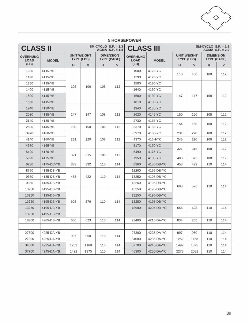
89
5 HORSEPOWER
CLASS II SM-CYCLO S.F. = 1.3AGMA S.F. = 1.4
OVERHUNGLOAD(LB)
MODEL
UNIT WEIGHTTYPE (LBS)
H V
DIMENSIONTYPE (PAGE)
H V
CLASS III SM-CYCLO S.F. = 1.6AGMA S.F. = 2.0
OVERHUNGLOAD(LB)
MODEL
UNIT WEIGHTTYPE (LBS)
H V
DIMENSIONTYPE (PAGE)
H V
1080 4115-YB 1080 4125-YC110 106 108 112
1190 4115-YB 1290 4125-YC
1350 4115-YB108 106 108 112
1580 4130-YC
1400 4115-YB 1640 4130-YC
1500 4115-YB 1680 4130-YC 147 147 108 112
1560 4115-YB 1810 4130-YC
1940 4130-YB 1940 4135-YC
2030 4135-YB 147 147 108 112 2620 4145-YC 150 150 108 112
2140 4135-YB 2730 4155-YC154 150 108 112
2890 4145-YB 150 150 108 112 3370 4155-YC
3970 4160-YB 3970 4160-YC 231 220 108 112
4140 4160-YB 231 220 108 112 4370 416H-YC 245 220 108 112
4370 4165-YB 5170 4170-YC321 315 108 112
5490 4170-YB321 315 108 112
5490 4175-YC
5920 4175-YB 7950 4180-YC 403 372 108 112
6230 4175-DC-YB 339 332 110 114 8360 4185-DB-YC 453 422 110 114
8750 4185-DB-YB 12200 4195-DB-YC
9380 4185-DB-YB 453 422 110 114 13250 4195-DB-YC
9380 4185-DB-YB 13260 4195-DB-YC603 576 110 114
13250 4195-DB-YB 13250 4195-DB-YC
13250 4195-DB-YB 13250 4195-DB-YC
13250 4195-DB-YB 603 576 110 114 13250 4195-DB-YC
13250 4195-DB-YB 18900 4205-DB-YC 656 623 110 114
13250 4195-DB-YB
18900 4205-DB-YB 656 623 110 114 23400 4215-DA-YC 834 755 110 114
27300 4225-DA-YB997 950 110 114
27300 4225-DA-YC 997 960 110 114
27300 4225-DA-YB 34000 4235-DA-YC 1252 1168 110 114
34000 4235-DA-YB 1252 1168 110 114 37700 4245-DA-YC 1492 1375 110 114
37700 4245-DA-YB 1492 1375 110 114 46300 4255-DA-YC 2273 2081 110 114

90
RATING TABLE
7.5 HORSEPOWER
CLASS I SM-CYCLO S.F. = 1.0AGMA S.F. = 1.0
OUTPUTRPM RATIO
OUTPUTTORQUE(IN. LB.)
OVERHUNGLOAD(LB)
MODEL
UNIT WEIGHTTYPE (LBS)
H V
DIMENSIONTYPE (PAGE)
H V
292.00 6 1500 1080 4125-YA
219.00 8 2000 1290 4125-YA
159.00 11 2750 1370 4125-YA125 121 108 112
135.00 13 3250 1410 4125-YA
117.00 15 3750 1510 4125-YA
103.00 17 4250 1550 4125-YA
83.30 21 5250 1940 4135-YA163 163 108 112
70.00 25 6250 2030 4135-YA
60.30 29 7250 2730 4145-YA 165 165 108 112
50.00 35 8740 3370 4155-YA 169 165 108 112
40.70 43 10700 3970 4160-YA246 235 108 112
34.30 51 12700 4140 4165-YA
29.70 59 14700 4880 416H-YA 260 235 108 112
24.60 71 17700 5490 4175-YA 337 330 108 112
20.10 87 21700 7950 4180-YA 420 389 108 112
17.20 102 23400 8360 4185-DB-YA469 438 110 114
14.50 121 27800 8750 4185-DB-YA
10.60 165 37900 13250 4195-DB-YA
10.10 174 39900 13250 4195-DB-YA
9.36 187 42900 13250 4195-DB-YA618 592 110 114
8.33 210 48200 13250 4195-DB-YA
7.58 231 53000 13250 4195-DB-YA
6.78 258 59200 13250 4195-DB-YA
5.49 319 73200 23400 4215-DA-YA 849 770 110 114
4.02 435 99900 27300 4225-DA-YA1012 996 110 114
3.55 493 113000 27300 4225-DA-YA
2.39 731 168000 37700 4245-DA-YA 1507 1390 110 114
2.08 841 193000 46300 4255-DA-YA 2288 2097 110 114

91
7.5 HORSEPOWER
CLASS II SM-CYCLO S.F. = 1.3AGMA S.F. = 1.4
OVERHUNGLOAD(LB)
MODEL
UNIT WEIGHTTYPE (LBS)
H V
DIMENSIONTYPE (PAGE)
H V
CLASS III SM-CYCLO S.F. = 1.6AGMA S.F. = 2.0
OVERHUNGLOAD(LB)
MODEL
UNIT WEIGHTTYPE (LBS)
H V
DIMENSIONTYPE (PAGE)
H V
1080 4125-YB125 121 108 112
1250 4130-YC
1290 4125-YB 1390 4130-YC163 163 108 112
1580 4130-YB 1580 4135-YC
1640 4130-YB163 163 108 112
1640 4135-YC
1680 4130-YB 2270 4145-YC165 165 108 112
1810 4130-YB 2340 4145-YC
2510 4145-YB 165 165 108 112 3150 4160-YC
3070 4155-YB 169 165 108 112 3320 4160-YC246 235 108 112
3480 4160-YB 3480 4165-YC
3700 4165-YB 246 235 108 112 3700 4165-YC
3970 4165-YB 4700 4170-YC337 330 108 112
4910 4170-YB337 330 108 112
4910 4175-YC
5170 4175-YB 6940 4180-YC420 389 108 112
7380 4180-YB420 389 108 112
7380 4185-YC
7950 4185-YB 11100 4190-YC 583 548 108 112
8360 4185-DB-YB 469 438 110 114 11700 4195-DB-YC618 592 110 114
12200 4195-DB-YB 12200 4195-DB-YC
13250 4195-DB-YB618 592 110 114
18900 4205-DB-YC671 638 110 114
13250 4195-DB-YB 18900 4205-DB-YC
13250 4195-DB-YB
23400 4215-DB-YB891 843 110 114
26600 4225-DB-YC 1111 1067 110 114
23400 4215-DB-YB 23400 4215-DB-YC 891 843 110 114
26600 4225-DB-YB 1111 1067 110 114 26600 4225-DB-YC 1111 1067 110 114
34000 4235-DA-YB1267 1184 110 114
37700 4245-DA-YC 1507 1390 110 114
34000 4235-DA-YB 46300 4255-DA-YC 2288 2097 110 114
46300 4255-DA-YB 2288 2097 110 114 56400 4265-DA-YC3005 2849 110 114
56400 4265-DA-YB 3005 2849 110 114 56400 4265-DA-YC

92
RATING TABLE
10 HORSEPOWER
CLASS I SM-CYCLO S.F. = 1.0AGMA S.F. = 1.0
OUTPUTRPM RATIO
OUTPUTTORQUE(IN. LB.)
OVERHUNGLOAD(LB)
MODEL
UNIT WEIGHTTYPE (LBS)
H V
DIMENSIONTYPE (PAGE)
H V
292.00 6 2000 1080 4130-YA
219.00 8 2670 1290 4130-YA
159.00 11 3660 1580 4135-YA 233 233 108 112
135.00 13 4330 1640 4135-YA
117.00 15 5000 1680 4135-YA
103.00 17 5660 1810 4135-YA
83.30 21 7000 2510 4145-YA 235 235 108 112
70.00 25 8330 3070 4155-YA 240 235 108 112
60.30 29 9660 3480 4165-YA
50.00 35 11700 3700 4165-YA 317 306 108 112
40.70 43 14300 3970 4165-YA
34.30 51 17000 4910 4175-YA409 403 108 112
29.70 59 19700 5170 4175-YA
24.60 71 23700 7380 4185-YA493 462 108 112
20.10 87 29000 7950 4185-YA
17.20 102 31200 8360 4185-DB-YA 539 508 110 114
14.50 121 37000 12200 4195-DB-YA
10.60 165 50500 13250 4195-DB-YA 689 662 110 114
10.10 174 53300 13250 4195-DB-YA
7.58 231 70700 23400 4215-DB-YA961 913 110 114
6.78 258 79000 23400 4215-DB-YA
5.49 319 97700 26600 4225-DB-YA 1184 1140 110 114
4.02 435 133000 34000 4235-DA-YA1338 1254 110 114
3.55 493 151000 34000 4235-DA-YA
2.39 731 224000 46300 4255-DA-YA 2354 2156 110 114
2.08 841 257000 56400 4265-DA-YA 3069 2915 110 114

93
10 HORSEPOWER
CLASS II SM-CYCLO S.F. = 1.3AGMA S.F. = 1.4
OVERHUNGLOAD(LB)
MODEL
UNIT WEIGHTTYPE (LBS)
H V
DIMENSIONTYPE (PAGE)
H V
CLASS III SM-CYCLO S.F. = 1.6AGMA S.F. = 2.0
OVERHUNGLOAD(LB)
MODEL
UNIT WEIGHTTYPE (LBS)
H V
DIMENSIONTYPE (PAGE)
H V
1250 4135-YB 1960 4155-YC
1390 4135-YB233 233 108 112
2170 4155-YC 240 235 108 112
1580 4135-YB 2430 4155-YC
1640 4135-YB 2640 4160-YC
2270 4145-YB235 235 108 112
2650 4160-YC
2340 4145-YB 2930 4160-YC 317 306 108 112
3150 4160-YB 3150 4165-YC
3320 4160-YB317 306 108 112
3320 4165-YC
3480 4165-YB 4100 4170-YC409 403 108 112
3700 4165-YB 4360 4175-YC
4700 4175-YB 409 403 108 112 6310 4180-YC493 462 108 112
6600 4180-YB 6600 4185-YC
6940 4185-YB 493 462 108 112 9710 4190-YC
7380 4185-YB 10300 4195-YC 649 614 108 112
11100 4190-YB 649 614 108 112 11100 4195-YC
11700 4195-DB-YB689 662 110 114
12200 4195-DB-YB 22200 4215-DB-YC 961 913 110 114
23400 4215-DB-YB 961 913 110 114 25900 4225-DB-YC
18900 4205-DB-YB 741 708 110 114 26400 4225-DB-YC 1184 1140 110 114
26600 4225-DB-YB1184 1140 110 114
26600 4225-DB-YC
26600 4225-DB-YB 33100 4235-DA-YC 1338 1254 110 114
33100 4235-DA-YB 1338 1254 110 114 35900 4245-DB-YC 1615 1525 110 114
37700 4245-DA-YB 1577 1461 110 114 46300 4255-DA-YC2354 2156 110 114
46300 4255-DA-YB 2354 2156 110 114 46300 4255-DA-YC
56400 4265-DA-YB3069 2915 110 114
56400 4265-DA-YC 3069 2915 110 114
56400 4265-DA-YB

94
RATING TABLE
15 HORSEPOWER
CLASS I SM-CYCLO S.F. = 1.0AGMA S.F. = 1.0
OUTPUTRPM RATIO
OUTPUTTORQUE(IN. LB.)
OVERHUNGLOAD(LB)
MODEL
UNIT WEIGHTTYPE (LBS)
H V
DIMENSIONTYPE (PAGE)
H V
292.00 6 3000 1960 4155-YA
219.00 8 4000 2170 4155-YA
159.00 11 5500 2430 4155-YA 306 301 108 112
135.00 13 6480 2500 4155-YA
117.00 15 7480 2610 4155-YA
103.00 17 8500 2930 4160-YA
83.30 21 10500 3150 4160-YA 387 376 108 112
70.00 25 12500 3320 4165-YA
60.30 29 14500 3650 416H-YA 400 376 108 112
50.00 35 17500 4360 4175-YA 477 471 108 112
40.70 43 21500 6310 4180-YA561 530 108 112
34.30 51 25500 6600 4185-YA
29.70 59 29400 9710 4190-YA
24.60 71 35500 10300 4190-YA 717 682 108 112
20.10 87 43500 11100 4195-YA
14.50 121 55400 22200 4215-DB-YA
10.60 165 75800 23400 4215-DB-YA 1032 983 110 114
10.10 174 79600 23400 4215-DB-YA
7.58 231 106000 26600 4225-DB-YA1252 1208 110 114
6.78 258 119000 26600 4225-DB-YA
5.49 319 146000 33100 4235-DA-YA 1408 1324 110 114
4.94 354 163000 34500 4245-DA-YA 1648 1531 110 114
4.02 435 200000 45000 4255-DA-YA
3.70 473 217000 45000 4255-DA-YA2431 2244 110 114
3.55 493 226000 45000 4255-DA-YA
3.35 522 240000 45000 4255-DA-YA
2.70 649 298000 54900 4265-DA-YA3146 2992 110 114
2.39 731 336000 54900 4265-DA-YA

95
15 HORSEPOWER
CLASS II SM-CYCLO S.F. = 1.3AGMA S.F. = 1.4
OVERHUNGLOAD(LB)
MODEL
UNIT WEIGHTTYPE (LBS)
H V
DIMENSIONTYPE (PAGE)
H V
CLASS III SM-CYCLO S.F. = 1.6AGMA S.F. = 2.0
OVERHUNGLOAD(LB)
MODEL
UNIT WEIGHTTYPE (LBS)
H V
DIMENSIONTYPE (PAGE)
H V
1960 4155-YB 2030 4165-YC
2170 4155-YB 306 301 108 112 2250 4165-YC
2430 4155-YB 2560 4165-YC 387 376 108 112
2640 4165-YB 2640 4165-YC
2650 4165-YB387 376 108 112
2650 4165-YC
2930 4165-YB 3460 4170-YC
3150 4165-YB 3730 4175-YC 477 471 108 112
3890 4170-YB477 471 108 112
3890 4175-YC
4100 4175-YB 5510 4185-YC561 530 108 112
5860 4180-YB561 530 108 112
5860 4185-YC
6310 4185-YB 8830 4190-YC717 682 108 112
9230 4190-YB 9230 4195-YC
9710 4195-YB 717 682 108 112 17800 4205-YC 766 733 108 112
10300 4195-YB
18900 4205-YB 766 733 108 112 18900 4215-YC 948 906 108 112
23330 4225-DB-YB 29100 4235-DB-YC1481 1397 110 114
25900 4225-DB-YB 1252 1208 110 114 32300 4235-DB-YC
26400 4225-DB-YB
33100 4235-DB-YB 1481 1397 110 114 34500 4245-DB-YC 1703 1593 110 114
33100 4235-DA-YB 1408 1324 110 114 34500 4245-DA-YC 1648 1531 110 114
45000 4255-DB-YB 2576 2396 110 114 45000 4255-DB-YC 2576 2396 110 114
45000 4255-DA-YB 2431 2244 110 114 46300 4255-DA-YC 2431 2244 110 114
54900 4265-DA-YB3146 2992 110 114
54900 4265-DA-YC3146 2992 110 114
54900 4265-DA-YB 54900 4265-DA-YC
54900 4265-DA-YB
55700 4275-DA-YB 5643 6039 110 114 55700 4275-DA-YC 5643 6039 110 114
55700 4275-DA-YB 5643 6039 110 114

96
RATING TABLE
20 HORSEPOWER
CLASS I SM-CYCLO S.F. = 1.0AGMA S.F. = 1.0
OUTPUTRPM RATIO
OUTPUTTORQUE(IN. LB.)
OVERHUNGLOAD(LB)
MODEL
UNIT WEIGHTTYPE (LBS)
H V
DIMENSIONTYPE (PAGE)
H V
292.00 6 4000 1960 4155-YA
219.00 8 5330 2170 4155-YA 348 343 108 112
159.00 11 7330 2430 4155-YA
135.00 13 8660 2640 4165-YA
117.00 15 9900 2650 4165-YA429 418 108 112
103.00 17 11300 2930 4165-YA
83.30 21 14000 3150 4165-YA
70.00 25 16700 3890 4175-YA519 513 108 112
60.30 29 19300 4100 4175-YA
50.00 35 23300 5860 4180-YA616 585 108 112
40.70 43 28600 6310 4185-YA
34.30 51 34000 9230 4195-YA
29.70 59 39300 9710 4195-YA 759 724 108 112
24.60 71 47300 10300 4195-YA
20.10 87 58000 18900 4205-YA 807 774 108 122
14.50 121 87100 24100 4225-YA(9) 1320 1294 108 112
10.60 165 101000 25900 4225-DB-YA1294 1250 110 114
10.10 174 107000 26400 4225-DB-YA
7.58 231 141000 34500 4245-DB-YA 1758 1648 110 114
6.78 258 158000 34500 4245-DA-YA 1690 1573 110 114
5.49 319 195000 45000 4255-DB-YA 2618 2442 110 114
4.94 354 217000 45000 4255-DA-YA 2464 2288 110 114
4.02 435 266000 54900 4265-DA-YA
3.70 473 290000 54900 4265-DA-YA 3179 3025 110 114
3.55 493 302000 54900 4265-DA-YA
2.70 649 397000 55700 4275-DA-YA5676 6072 110 114
2.39 731 448000 55700 4275-DA-YA
NOMINAL O.P. RPM EXACT RATIO
(1) 106.0 11(2) 77.6 15(3) 55.5 21(4) 40.2 29(5) 27.1 43(6) 22.8 51(7) 19.7 59(8) 16.4 71(9) 13.4 87
(10) 14.7 119
(1) THRU (9) THESE UNITS ARE SUPPLIED WITH A 6 POLENOMINAL 1165 RPM MOTOR.
OUTPUT SPEEDS WILL BE SHOWN IN FOOTNOTES.

97
20 HORSEPOWER
CLASS II SM-CYCLO S.F. = 1.3AGMA S.F. = 1.4
OVERHUNGLOAD(LB)
MODEL
UNIT WEIGHTTYPE (LBS)
H V
DIMENSIONTYPE (PAGE)
H V
CLASS III SM-CYCLO S.F. = 1.6AGMA S.F. = 2.0
OVERHUNGLOAD(LB)
MODEL
UNIT WEIGHTTYPE (LBS)
H V
DIMENSIONTYPE (PAGE)
H V
2030 4165-YB 2400 4170-YC 519 513 108 112
2250 4165-YB 429 418 108 112
2560 4165-YB 3020 4175-YC
2640 4165-YB 3130 4175-YC519 513 108 112
2970 416H-YB 442 418 108 112 3280 4175-YC
3460 4175-YB519 513 108 112
4650 4180-YC
3730 4175-YB 5010 4185-YC 616 585 108 112
5230 4180-YB 5230 4185-YC
5510 4185-YB 616 585 108 112 7710 4190-YC
5860 4185-YB 8190 4195-YC 759 724 108 112
8830 4195-YB759 724 108 112
8830 4195-YC
9230 4195-YB
17800 4205-YB 807 774 108 112 18000 4215-YC 990 948 108 112
20300 4215-YB 990 948 108 112 21400 4215-YC(7) 1133 1091 108 112
30100 4235-YB(9) 1496 1426 108 112 33500 4245-DB-YC1758 1648 110 114
32300 4235-DB-YB 1536 1452 110 114 34500 4245-DB-YC
32900 4235-DA-YB 1450 1366 110 114
45000 4255-DB-YB 2618 2442 110 114 45000 4255-DB-YC 2618 2442 110 114
45000 4255-DA-YB 2464 2288 110 114 45000 4255-DA-YC 2464 2288 110 114
54900 4265-DA-YB 3179 3025 110 114 54900 4265-DA-YC 3179 3025 110 114
54900 4265-DA-YB 3179 3025 110 114 55700 4275-DA-YC 5676 6072 110 114
55700 4275-DA-YB 5676 6072 110 114

98
RATING TABLE
25 HORSEPOWER
CLASS I SM-CYCLO S.F. = 1.0AGMA S.F. = 1.0
OUTPUTRPM RATIO
OUTPUTTORQUE(IN. LB.)
OVERHUNGLOAD(LB)
MODEL
UNIT WEIGHTTYPE (LBS)
H V
DIMENSIONTYPE (PAGE)
H V
292.00 6 5000 2030 416H-YA
219.00 8 6660 2250 416H-YA
159.00 11 9160 2560 416H-YA 579 568 108 112
135.00 13 10800 2640 416H-YA
117.00 15 12500 2650 416H-YA
103.00 17 14200 3460 4175-YA669 662 108 112
83.30 21 17500 3730 4175-YA
70.00 25 20800 5230 4180-YA
60.30 29 24200 5510 4185-YA 752 722 108 112
50.00 35 29100 5860 4185-YA
40.70 43 35800 8830 4190-YA917 882 108 112
34.30 51 42500 9230 4195-YA
29.70 59 49100 17800 4205-YA 964 931 108 112
20.10 87 72500 20300 4215-YA 1133 1091 108 112
14.50 121 92600 29100 4235-DB-YA1672 1588 110 114
10.60 165 126000 32300 4235-DB-YA
7.58 231 177000 45000 4255-DB-YA 2783 2596 110 114
6.78 258 197000 34500 4245-DA-YA 1839 1723 110 114
5.49 319 244000 45000 4255-DB-YA 2783 2596 110 114
4.02 435 333000 54900 4265-DA-YA 3344 3190 110 114
NOMINAL O.P. RPM EXACT RATIO
(1) 106.0 11(2) 77.6 15(3) 55.5 21(4) 40.2 29(5) 27.1 43(6) 22.8 51(7) 19.7 59(8) 16.4 71(9) 13.4 87
(10) 14.7 119
(1) THRU (9) THESE UNITS ARE SUPPLIED WITH A 6 POLENOMINAL 1165 RPM MOTOR.
OUTPUT SPEEDS WILL BE SHOWN IN FOOTNOTES.

99
25 HORSEPOWER
CLASS II SM-CYCLO S.F. = 1.3AGMA S.F. = 1.4
OVERHUNGLOAD(LB)
MODEL
UNIT WEIGHTTYPE (LBS)
H V
DIMENSIONTYPE (PAGE)
H V
CLASS III SM-CYCLO S.F. = 1.6AGMA S.F. = 2.0
OVERHUNGLOAD(LB)
MODEL
UNIT WEIGHTTYPE (LBS)
H V
DIMENSIONTYPE (PAGE)
H V
2400 4170-YB 669 662 108 112
3020 4175-YB 4060 4185-YC
3130 4175-YB 669 662 108 112 4210 4185-YC
3280 4175-YB 4420 4185-YC 752 722 108 112
4650 4180-YB 4650 4185-YC
5010 4185-YB 752 722 108 112 5010 4185-YC
5230 4185-YB 7320 4195-YC917 882 108 112
5510 4190-YB917 882 108 112
7710 4195-YC
8190 4195-YB
16300 4205-YB 964 931 108 112 16300 4205-YC 964 931 108 112
18000 4215-YB 1133 1091 108 112 18000 4215-YC 1133 1091 108 112
21400 4225-YB 1320 1294 108 112 26700 4235-YC(7) 1536 1465 108 112
32400 4245-DB-YB1894 1784 110 114
33500 4245-YC(9) 1802 1698 108 112
34500 4245-DB-YB 54600 4265-DA-YC3344 3190 110 114
45000 4255-DB-YB 2783 2596 110 114 54900 4265-DA-YC
45000 4255-DA-YB 2618 2431 110 114
54900 4265-DA-YB 3344 3190 110 114

100
RATING TABLE
30 HORSEPOWER
CLASS I SM-CYCLO S.F. = 1.0AGMA S.F. = 1.0
OUTPUTRPM RATIO
OUTPUTTORQUE(IN. LB.)
OVERHUNGLOAD(LB)
MODEL
UNIT WEIGHTTYPE (LBS)
H V
DIMENSIONTYPE (PAGE)
H V
292.00 6 6000 2130 416H-YA
219.00 8 8000 2370 416H-YA 592 568 108 112
159.00 11 11000 2670 416H-YA
135.00 13 13000 3130 4175-YA669 662 108 112
117.00 15 15000 3280 4175-YA
103.00 17 17000 4650 4180-YA
83.30 21 21000 5010 4180-YA 752 722 108 112
70.00 25 25000 5230 4185-YA
60.30 29 29000 7710 4190-YA
50.00 35 35000 8190 4195-YA 917 882 108 112
40.70 43 43000 8830 4195-YA
29.70 59 59000 18000 4215-YA 1133 1091 108 112
20.10 87 86900 20300 4215-YA(7) 1162 1120 108 112
14.50 121 121000 30100 4235-YA(9) 1536 1465 108 112
10.60 165 165000 34500 4245-DB-YA 1894 1784 110 114
7.58 231 231000 45000 4255-DB-YA 2783 2596 110 114
6.78 258 258000 45000 4255-DA-YA 2618 2431 110 114
5.49 319 319000 54900 4265-DA-YA 3344 3190 110 114
3.70 473 434000 55700 4275-DA-YA 5841 6237 110 114
NOMINAL O.P. RPM EXACT RATIO
(1) 106.0 11(2) 77.6 15(3) 55.5 21(4) 40.2 29(5) 27.1 43(6) 22.8 51(7) 19.7 59(8) 16.4 71(9) 13.4 87
(10) 14.7 119
(1) THRU (9) THESE UNITS ARE SUPPLIED WITH A 6 POLENOMINAL 1165 RPM MOTOR.
OUTPUT SPEEDS WILL BE SHOWN IN FOOTNOTES.

101
30 HORSEPOWER
CLASS II SM-CYCLO S.F. = 1.3AGMA S.F. = 1.4
OVERHUNGLOAD(LB)
MODEL
UNIT WEIGHTTYPE (LBS)
H V
DIMENSIONTYPE (PAGE)
H V
CLASS III SM-CYCLO S.F. = 1.6AGMA S.F. = 2.0
OVERHUNGLOAD(LB)
MODEL
UNIT WEIGHTTYPE (LBS)
H V
DIMENSIONTYPE (PAGE)
H V
4060 4180-YB 5680 4190-YC
4210 4180-YB 5890 4190-YC
4420 4180-YB 752 722 108 112 6170 4190-YC917 882 108 112
4650 4185-YB 6500 4190-YC
5010 4185-YB 7000 4195-YC
7320 4195-YB917 882 108 112
7320 4195-YC
7710 4195-YB 14400 4205-YC 964 931 108 112
16300 4205-7B 964 931 108 112 16500 4215-YC 1133 1091 108 112
18000 4215-YB 1133 1091 108 112 19000 4225-YC 1320 1294 108 112
26700 4235-YB(7) 1536 1465 108 112 29700 4245-YC(7) 1802 1698 108 112
33500 4245-YB(9) 1802 1698 108 112 41000 4255-YC(9) 2530 2332 108 112
44700 4255-DB-YB 2783 2596 110 114 54600 4265-DA-YC 3344 3190 110 114
54900 4264-DA-YB 3344 3190 110 114

102
RATING TABLE
40 HORSEPOWER
CLASS I SM-CYCLO S.F. = 1.0AGMA S.F. = 1.0
OUTPUTRPM RATIO
OUTPUTTORQUE(IN. LB.)
OVERHUNGLOAD(LB)
MODEL
UNIT WEIGHTTYPE (LBS)
H V
DIMENSIONTYPE (PAGE)
H V
159.00 11 14700 4060 4185-YA
135.00 13 17300 4210 4185-YA
117.00 15 20000 4420 4185-YA 790 760 108 112
103.00 17 22700 4650 4185-YA
83.30 21 28000 5010 4185-YA
70.00 25 33300 7320 4195-YA 950 915 108 11260.30 29 38600 7710 4195-YA
40.70 43 57300 16300 4205-YA 992 959 108 112
29.70 59 78600 18000 4215-YA 1162 1120 108 112
20.10 87 116000 26700 4235-YA(7) 1701 1630 108 112
14.50 121 161000 33500 4245-YA(9) 1967 1863 108 112
10.60 165 220000 54600 4265-DA-YA3377 3223 110 112
7.58 231 308000 54900 4265-DA-YA
NOMINAL O.P. RPM EXACT RATIO
(1) 106.0 11(2) 77.6 15(3) 55.5 21(4) 40.2 29(5) 27.1 43(6) 22.8 51(7) 19.7 59(8) 16.4 71(9) 13.4 87
(10) 14.7 119
(1) THRU (9) THESE UNITS ARE SUPPLIED WITH A 6 POLENOMINAL 1165 RPM MOTOR.
OUTPUT SPEEDS WILL BE SHOWN IN FOOTNOTES.

103
40 HORSEPOWER
CLASS II SM-CYCLO S.F. = 1.3AGMA S.F. = 1.4
OVERHUNGLOAD(LB)
MODEL
UNIT WEIGHTTYPE (LBS)
H V
DIMENSIONTYPE (PAGE)
H V
CLASS III SM-CYCLO S.F. = 1.6AGMA S.F. = 2.0
OVERHUNGLOAD(LB)
MODEL
UNIT WEIGHTTYPE (LBS)
H V
DIMENSIONTYPE (PAGE)
H V
5680 4195-YB 11000 4205-YC 992 959 108 112
5890 4195-YB
6170 4195-YB950 915 108 112
11800 4205-YC 992 959 108 112
6500 4195-YB 12400 4205-YC(1) 1111 1078 108 112
7000 4195-YB 13200 4205-YC 992 959 108 112
7320 4195-YB
14400 4205-YB 992 959 108 112 14600 4215-YC 1162 1120 108 112
16500 4215-YB 1162 1120 108 112 17400 4225-YC 1349 1322 108 112
19600 4225-YB(5) 1467 1441 108 112 24300 4235-YC(5) 1701 1630 108 112
29700 4245-YB(7) 1967 1863 108 112 36300 4255-YC(7) 2695 2508 108 112
41000 4255-YB(9) 2695 2508 108 112 50000 4265-YC(9) 3212 3058 108 112

104
RATING TABLE
50 HORSEPOWER
CLASS I SM-CYCLO S.F. = 1.0AGMA S.F. = 1.0
OUTPUTRPM RATIO
OUTPUTTORQUE(IN. LB.)
OVERHUNGLOAD(LB)
MODEL
UNIT WEIGHTTYPE (LBS)
H V
DIMENSIONTYPE (PAGE)
H V
159.00 11 18300 5680 4195-YA
135.00 13 21700 5890 4195-YA
117.00 15 25000 6170 4195-YA 1034 999 108 112103.00 17 28300 6500 4195-YA
83.30 21 35000 7000 4195-YA
70.00 25 41600 7320 4195-YA
60.30 29 48300 14400 4205-YA 1111 1078 108 112
40.70 43 71600 16500 4215-YA 1283 1241 108 112
29.70 59 98300 19000 4225-YA 1467 1441 108 112
20.10 87 145000 29700 4245-YA(7) 1967 1863 108 112
14.50 121 202000 41000 4255-YA(9) 2695 2508 108 112
10.60 165 275000 54600 4265-DA-YA 3454 3300 110 114
60 HORSEPOWER
CLASS I SM-CYCLO S.F. = 1.0AGMA S.F. = 1.0
OUTPUTRPM RATIO
OUTPUTTORQUE(IN. LB.)
OVERHUNGLOAD(LB)
MODEL
UNIT WEIGHTTYPE (LBS)
H V
DIMENSIONTYPE (PAGE)
H V
159.00 11 22000 11000 4205-YA
117.00 15 30000 11800 4205-YA1111 1078 108 112
83.30 21 42000 13200 4205-YA
60.30 29 48000 14400 4205-YA
40.70 43 86000 17400 4225-YA 1467 1441 108 112
29.70 59 118000 24300 4235-YA(5) 1833 1762 108 112
20.10 87 174000 29700 4245-YA(7) 2103 2000 108 112
14.50 121 242000 50000 4265-YA(9) 3377 3223 108 112
NOMINAL O.P. RPM EXACT RATIO
(1) 106.0 11(2) 77.6 15(3) 55.5 21(4) 40.2 29(5) 27.1 43(6) 22.8 51(7) 19.7 59(8) 16.4 71(9) 13.4 87
(10) 14.7 119
(1) THRU (9) THESE UNITS ARE SUPPLIED WITH A 6 POLENOMINAL 1165 RPM MOTOR.
OUTPUT SPEEDS WILL BE SHOWN IN FOOTNOTES.

105
50 HORSEPOWER
CLASS II SM-CYCLO S.F. = 1.3AGMA S.F. = 1.4
OVERHUNGLOAD(LB)
MODEL
UNIT WEIGHTTYPE (LBS)
H V
DIMENSIONTYPE (PAGE)
H V
CLASS III SM-CYCLO S.F. = 1.6AGMA S.F. = 2.0
OVERHUNGLOAD(LB)
MODEL
UNIT WEIGHTTYPE (LBS)
H V
DIMENSIONTYPE (PAGE)
H V
11000 4205-YB 1111 1078 108 112 11100 4215-YC 1283 1241 108 112
11800 4205-YB 1111 1078 108 112 11900 4215-YC 1283 1241 108 112
12400 4205-YB(1) 1111 1078 108 112 12600 4215-YC(1) 1283 1241 108 112
13200 4205-YB 1111 1078 108 112 13400 4215-YC 1283 1241 108 112
14600 4215-YB 1283 1241 108 112 15400 4225-YC 1467 1441 108 112
17400 4225-YB 1467 1441 108 112 21700 4235-YC(4) 1701 1630 108 112
24300 4235-YB(5) 1701 1630 108 112 27100 4245-YC(5) 1967 1863 108 112
36300 4255-YB(7) 2695 2508 108 112 36300 4255-YC(7) 2695 2508 108 112
50000 4265-YB(9) 3212 3058 108 112
60 HORSEPOWER
CLASS II SM-CYCLO S.F. = 1.3AGMA S.F. = 1.4
OVERHUNGLOAD(LB)
MODEL
UNIT WEIGHTTYPE (LBS)
H V
DIMENSIONTYPE (PAGE)
H V
CLASS III SM-CYCLO S.F. = 1.6AGMA S.F. = 2.0
OVERHUNGLOAD(LB)
MODEL
UNIT WEIGHTTYPE (LBS)
H V
DIMENSIONTYPE (PAGE)
H V
11000 4205-YB1111 1078 108 112
11100 4215-YC1283 1241 108 112
11800 4205-YB 11900 4215-YC
13400 4215-YB 1283 1241 108 112 14100 4225-YC 1467 1441 108 112
15400 4225-YB 1467 1441 108 112 15800 4225-YC(3) 1650 1624 108 112
21700 4235-YB(4) 1833 1762 108 112 24100 4245-YC(4) 2103 2000 108 112
27100 4245-YB(5) 2103 2000 108 112 33200 4255-YC(5) 2805 2618 108 112
36300 4255-YB(7) 2803 2618 108 112 44300 4265-YC(7) 3377 3223 108 112

106
RATING TABLE
75 HORSEPOWER
CLASS I SM-CYCLO S.F. = 1.0AGMA S.F. = 1.0
OUTPUTRPM RATIO
OUTPUTTORQUE(IN. LB.)
OVERHUNGLOAD(LB)
MODEL
UNIT WEIGHTTYPE (LBS)
H V
DIMENSIONTYPE (PAGE)
H V
159.00 11 27500 11000 4205-BP-YA108 112
117.00 15 37500 11800 4205-BP-YA
83.30 21 52500 13400 4215-YA 1487 1445 108 112
60.30 29 72500 15400 4225-YA 1650 1624 108 112
40.70 43 107000 21700 4235-YA(4) 1951 1881 108 112
29.70 59 147000 27100 4245-YA(5) 2211 2105 108 112
20.10 87 217000 36300 4255-YA(7) 2926 2728 108 112
NOMINAL O.P. RPM EXACT RATIO
(1) 106.0 11(2) 77.6 15(3) 55.5 21(4) 40.2 29(5) 27.1 43(6) 22.8 51(7) 19.7 59(8) 16.4 71(9) 13.4 87
(10) 14.7 119
(1) THRU (9) THESE UNITS ARE SUPPLIED WITH A 6 POLENOMINAL 1165 RPM MOTOR.
OUTPUT SPEEDS WILL BE SHOWN IN FOOTNOTES.
100 HORSEPOWER
CLASS I SM-CYCLO S.F. = 1.0AGMA S.F. = 1.0
OUTPUTRPM RATIO
OUTPUTTORQUE(IN. LB.)
OVERHUNGLOAD(LB)
MODEL
UNIT WEIGHTTYPE (LBS)
H V
DIMENSIONTYPE (PAGE)
H V
159.00 11 36600 11700 4225-BP-YA
117.00 15 50000 12600 4225-BP-YA
83.30 21 70000 14100 4225-BP-YA
60.30 29 96600 19800 4235-BP-YA(3) CF CF 108 112
40.70 43 143000 24100 4245-BP-YA(4)
29.70 59 197000 33200 4255-BP-YA(5)
20.10 87 290000 44300 4265-BP-YA(7)

107
75 HORSEPOWER
CLASS II SM-CYCLO S.F. = 1.3AGMA S.F. = 1.4
OVERHUNGLOAD(LB)
MODEL
UNIT WEIGHTTYPE (LBS)
H V
DIMENSIONTYPE (PAGE)
H V
CLASS III SM-CYCLO S.F. = 1.6AGMA S.F. = 2.0
OVERHUNGLOAD(LB)
MODEL
UNIT WEIGHTTYPE (LBS)
H V
DIMENSIONTYPE (PAGE)
H V
11700 4225-YB 11700 4225-YC1650 1624 108 112
12600 4225-YB 1650 1624 108 112 12600 4225-YC
14100 4225-YB 17600 4235-YC(2)1951 1881 108 112
19800 4235-YB(3) 1951 1881 108 112 19800 4235-YC(3)
24100 4245-YB(4) 2211 2105 108 112 29500 4255-YC(4) 2926 2728 108 112
33200 4255-YB(5) 2926 2728 108 112 40500 4265-BP-YC(5)CF CF 108 112
44300 4265-BP-YB(7) CF CF 108 112 55700 4275-BP-YC(7)
100 HORSEPOWER
CLASS II SM-CYCLO S.F. = 1.3AGMA S.F. = 1.4
OVERHUNGLOAD(LB)
MODEL
UNIT WEIGHTTYPE (LBS)
H V
DIMENSIONTYPE (PAGE)
H V
CLASS III SM-CYCLO S.F. = 1.6AGMA S.F. = 2.0
OVERHUNGLOAD(LB)
MODEL
UNIT WEIGHTTYPE (LBS)
H V
DIMENSIONTYPE (PAGE)
H V
11700 4225-BP-YB
12600 4225-BP-YB 18300 4245-BP-YC(1)
17600 4235-BP-YB(2) 19600 4245-BP-YC(2)
21900 4245-BP-YB(3) CF CF 108 112 26700 4255-BP-YC(3) CF CF 108 112
29500 4255-BP-YB(4) 36000 4265-BP-YC(4)
40500 4265-BP-YB(5) 57400 4275-BP-YC(5)
55700 4275-BP-YB(7)

108
MODEL A B C C2 D E F G H J P O BW MP AB L L2 MS
4075 1/8 5.67 3.31 10.43 11.77 3.149 2.36 2.36 0.39 0.35 1.38 4.33 7.36 1.61 4.88 4.72 3.07 4.41 1.541/4 11.34 12.32 7.36 5.20 4.72 3.98 4.96 1.54
4085 1/8 5.67 3.31 10.67 12.01 3.149 2.36 2.36 0.39 0.35 1.38 4.33 7.36 1.85 4.88 4.72 3.07 4.41 1.541/4, 1/3 11.58 12.56 7.36 5.20 4.72 3.98 4.96 1.541/2 12.36 13.35 7.36 5.20 4.72 4.37 5.35 1.54
4090 1/8 7.09 5.12 12.40 13.34 3.937 2.95 3.54 0.47 0.43 1.57 5.91 8.15 2.36 4.88 4.72 3.07 4.41 1.544095 1/4, 1/3 13.31 14.29 8.15 5.20 4.72 3.98 4.96 1.544097 1/2 14.10 15.08 8.15 5.20 4.72 4.37 5.36 1.54
3/4,1 14.92 16.61 8.39 5.83 4.49 3.82 5.51 3.671.5, 2 16.22 18.66 8.66 6.30 4.69 3.94 6.38 4.53
4100 1/4, 1/3 7.09 5.31 13.86 14.84 3.937 2.95 3.54 0.47 0.43 1.57 5.91 8.15 2.36 5.20 4.72 3.98 4.96 1.544105 1/2 14.65 15.63 8.15 5.20 4.72 4.37 5.36 1.54
3/4, 1 15.47 17.17 8.39 5.83 4.49 3.82 5.51 3.671.5, 2 16.77 19.21 8.66 6.30 4.69 3.94 6.38 4.533 17.56 20.04 8.90 6.81 4.96 4.13 6.61 4.77
410H 3/4, 1 7.09 5.31 15.47 17.17 4.724 2.95 3.54 0.47 0.43 1.77 6.30 8.39 2.36 5.83 4.49 3.82 5.51 3.671.5, 2 16.77 19.21 8.66 6.30 4.69 3.94 6.38 4.533 17.56 20.04 8.90 6.81 4.96 4.13 6.61 4.77
4110 1/2 9.06 6.10 15.94 16.93 4.724 3.74 4.53 0.59 0.55 2.17 8.03 8.94 3.23 5.20 4.72 4.37 5.35 1.544115 3/4, 1 16.65 18.35 9.17 5.83 4.49 3.82 5.51 3.67
1.5, 2 17.95 20.39 9.45 6.30 4.69 3.94 6.38 4.533 18.74 21.22 9.69 6.81 4.96 4.13 6.61 4.775 19.65 22.48 9.80 8.35 5.79 5.00 7.83 5.20
4125 5 9.06 6.10 19.65 22.48 5.512 3.74 4.53 0.59 0.55 2.36 8.03 10.67 3.23 8.35 5.79 5.00 7.83 5.207.5 21.38 24.21 10.67 8.35 5.79 5.00 7.83 5.20
4130 1 13.00 7.68 18.78 20.47 5.905 5.71 5.71 0.87 0.71 2.56 9.06 10.35 3.94 5.83 4.49 3.82 5.51 3.674135 1.5, 2 20.08 22.52 10.63 6.30 4.69 3.94 6.38 4.53
3 20.87 23.35 10.87 6.81 4.96 4.13 6.61 4.775 21.77 24.61 10.98 8.35 5.79 5.00 7.83 5.207.5 23.50 26.34 10.98 8.35 5.79 5.00 7.83 5.2010 25.98 30.12 12.01 10.16 7.76 8.96 13.09 8.86
4145 1.5, 2 13.00 7.68 20.87 23.31 5.905 5.71 5.71 0.87 0.71 2.56 9.06 10.47 4.72 6.30 4.69 3.94 6.38 4.533 21.65 24.13 10.71 6.81 4.96 4.13 6.61 4.775 22.56 25.39 10.98 8.35 5.79 5.00 7.83 5.207.5 24.29 27.13 10.98 8.35 5.79 5.00 7.83 5.2010 26.77 30.91 12.01 10.16 7.76 8.96 13.09 8.86
4155 2 13.00 7.68 20.87 23.31 6.299 5.71 5.71 0.87 0.71 2.76 10.47 10.87 4.72 6.30 4.69 3.94 6.38 4.533 21.65 24.13 11.10 6.81 4.96 4.13 6.61 4.775 22.56 25.39 11.38 8.35 5.79 5.00 7.83 5.207.5 24.29 27.13 11.38 8.35 5.79 5.00 7.83 5.2010 26.77 30.91 12.40 10.16 7.76 8.96 13.09 8.8615 29.37 32.91 13.03 12.76 9.13 10.75 14.29 9.7220 31.10 34.65 14.49 12.76 9.13 11.61 15.16 9.72
4160 3 16.14 9.37 23.54 26.02 6.299 7.28 5.91 0.98 0.71 2.95 12.52 12.20 5.47 6.81 4.96 4.13 6.61 4.774165 5 24.45 27.28 12.20 8.35 5.79 5.00 7.83 5.20
7.5 26.18 29.02 12.20 8.35 5.79 5.00 7.83 5.2010 28.66 32.80 12.60 10.16 7.76 8.96 13.09 8.8615 31.26 34.80 14.49 12.76 9.13 10.75 14.29 9.7220 32.99 36.54 14.49 12.76 9.13 11.61 15.16 9.72
416H 3 16.14 9.37 23.54 26.02 7.874 7.28 5.91 0.98 0.71 3.15 13.39 13.78 5.47 6.81 4.96 4.13 6.61 4.775 24.45 27.28 13.78 8.35 5.79 5.00 7.83 5.207.5 26.18 29.02 13.78 8.35 5.79 5.00 7.83 5.2015 31.26 34.80 16.06 12.76 9.13 10.75 14.29 9.7220 32.99 36.54 16.06 12.76 9.13 11.61 15.16 9.7225, 30 36.73 — 16.85 15.51 11.69 13.39 — —
MT WT WT2 U V KEY
— 16 19 0.500 0.98 1⁄8 x 1⁄8 x 0.79— 19 22— 17 20 0.750 1.18 3⁄16 x 3⁄16 x 1.06— 20 22— 24 26— 33 35 1.125 1.38 1⁄4 x 1⁄4 x 1.18— 36 37— 39 41
4.86 42 485.12 57 68— 42 44 1.125 1.38 1⁄4 x 1⁄4 x 1.18— 46 48
4.88 49 555.12 57 685.37 66 794.88 51 57 1.125 1.38 1⁄4 x 1⁄4 x 1.185.12 59 705.37 68 81— 69 71 1.500 2.17 3⁄8 x 3⁄8 x 1.77
4.88 68 755.12 77 885.37 86 99— 108 130— 110 132 1.500 2.17 3⁄8 x 3⁄8 x 1.77— 125 147
4.88 110 117 1.875 2.76 1⁄2 x 1⁄2 x 2.175.12 119 1305.37 125 141— 147 169— 163 185— 233 288
5.12 121 132 1.875 3.54 1⁄2 x 1⁄2 x 2.955.37 128 143— 150 172— 165 187— 235 290
5.12 125 136 1.875 3.54 1⁄2 x 1⁄2 x 2.955.37 132 147— 154 176— 169 191— 240 295— 306 378— 348 420
5.37 211 224 2.250 3.54 1⁄2 x 1⁄2 x 2.95— 231 253— 246 268— 317 372— 387 460— 429 502
5.37 224 238 2.250 3.54 1⁄2 x 1⁄2 x 2.95— 245 267— 260 282— 400 475— 442 515— 592 —
INTEGRAL FOOT MOUNT TYPE HM DIMENSIONS
OUTPUT SHAFT
SINGLEREDUCTION
MOTORHP
WEIGHT(LB)

109
MODEL A B C C2 D E F G H J P O BW MP AB L L2 MS
4170 5 16.93 13.19 26.77 29.61 7.874 7.48 10.83 1.18 0.87 3.15 14.25 14.57 4.92 8.35 5.79 5.00 7.83 5.204175 7.5 28.50 31.34 14.57 8.35 5.79 5.00 7.83 5.20
10 30.39 34.53 14.76 10.16 7.76 8.96 13.09 8.8615 32.99 36.54 16.42 12.76 9.13 10.75 14.29 9.7220 34.72 38.27 16.42 12.76 9.13 11.61 15.16 9.7225, 30 38.46 — 16.85 15.51 11.69 13.39 — —
4180 5 18.50 14.95 28.23 31.06 8.661 8.27 12.60 1.18 0.87 3.35 15.35 15.94 5.71 8.35 5.79 5.00 7.83 5.204185 7.5 29.96 32.80 15.94 8.35 5.79 5.00 7.83 5.20
10 31.85 35.98 15.94 10.16 7.76 8.96 13.09 8.8615 34.45 37.99 17.20 12.76 9.13 10.75 14.29 9.7220 36.18 39.72 17.20 12.76 9.13 11.61 15.16 9.7225, 30 39.92 — 17.64 15.51 11.69 13.39 — —
4190 7.5 20.87 17.32 33.74 36.57 9.842 9.45 14.96 1.38 1.02 3.54 17.76 18.31 6.69 8.35 5.79 5.00 7.83 5.204195 10 34.84 38.98 18.31 10.16 7.76 8.96 13.09 8.86
15 37.44 40.98 18.39 12.76 9.13 10.75 14.29 9.7220 39.17 42.72 18.39 12.76 9.13 11.61 15.16 9.7225, 30 42.91 — 20.12 15.51 11.69 13.39 — —40 42.91 — 20.12 15.51 11.69 13.39 — —50 47.44 — 20.12 15.51 11.69 16.93 — —
4205 15 20.87 17.32 39.29 42.83 9.843 8.66 14.17 1.38 1.02 3.94 18.54 20.87 8.46 12.76 9.13 10.75 14.29 9.7220 41.02 44.57 20.87 12.76 9.13 11.61 15.16 9.7225, 30 44.37 — 20.87 15.51 11.69 13.39 — —40 44.37 — 20.87 15.51 11.69 13.39 — —406, 506 49.90 — 20.87 15.51 11.69 16.93 — —50, 60 48.90 — 20.87 15.51 11.69 16.93 — —
4215 15 22.83 18.70 40.24 43.78 10.433 9.45 15.55 1.57 1.02 4.33 19.96 22.64 8.27 12.76 9.13 10.75 14.29 9.7220 41.97 45.51 22.64 12.76 9.13 11.61 15.16 9.72206, 25, 30 45.31 — 22.64 15.51 11.69 13.39 — —306, 40 45.31 — 22.64 15.51 11.69 13.39 — —506, 50, 60 49.84 — 22.64 15.51 11.69 16.93 — —75 52.01 — 22.64 19.06 16.22 18.31 — —
4225 206, 25, 30 24.41 24.07 46.89 — 11.024 10.63 16.54 1.57 1.30 4.53 21.61 24.02 9.06 15.51 11.69 13.39 —256, 40 46.89 — 24.02 15.51 11.69 13.39 —406, 50, 60 51.42 — 24.02 15.11 11.69 16.93 —606, 75 53.58 — 24.02 19.06 16.22 18.31 —
4235 206 26.38 22.05 49.33 — 11.811 11.42 18.11 1.77 1.30 4.72 23.27 26.26 10.24 15.51 11.69 13.39 —256, 306 49.33 — 26.26 15.51 11.69 13.39 —406, 506 53.86 — 26.26 15.51 11.69 16.93 —606 56.02 — 26.26 19.06 16.22 18.31 —756 59.17 — 26.26 19.09 16.22 19.88 —
4245 256, 306 28.35 22.83 50.47 — 13.189 12.40 18.90 1.77 1.54 5.04 25.08 28.70 10.35 15.51 11.69 13.39 — —406, 506 55.00 — 28.70 15.51 11.69 16.93 — —606 57.17 — 28.70 19.06 16.22 18.31 — —756 60.31 — 28.70 19.06 16.22 19.88 — —
4255 306 30.71 24.80 55.12 — 14.764 13.19 20.47 1.97 1.54 5.51 27.68 32.09 12.60 15.51 11.69 13.39 —406, 506 59.65 — 32.09 15.51 11.69 16.93 —606 61.81 — 32.09 19.06 16.22 18.31 —756 64.96 — 32.09 19.09 16.22 19.88 —
4265 406, 506 34.65 27.56 64.25 — 15.748 15.16 23.23 2.17 1.77 6.30 30.39 34.41 15.35 15.51 11.69 16.93 —606 64.42 — 19.06 16.22 18.31 —
MTWT WT2 U V KEY
— 321 343 2.750 3.54 5⁄8 x 5⁄8 x 3.15— 337 359— 409 462— 477 552— 519 592— 669 —— 403 425 3.125 4.33 3⁄4 x 3⁄4 x 3.74— 420 442— 493 546— 561 636— 616 678— 752 —— 583 605 3.625 5.31 7⁄8 x 7⁄8 x4.92— 649 704— 717 792
759 834— 917 —— 950 —— 1034 —— 766 843 3.875 6.50 1.0 x 1.0 x 6.50— 807 884— 964 —— 992 —— 1111 —— 1111 —— 948 1025 4.250 6.50 1.0 x 1.0 x 6.50— 990 1065— 1133 —— 1162 —— 1283 —— 1487 —
1320 — 4.625 6.50 1.25 x 7⁄8 x 6.501349 —1467 —1650 —1496 — 5.000 7.87 1.25 x 7⁄8 x 7.871536 —1701 —1833 —1951 —
— 1802 — 5.500 7.87 1.25 x 7⁄8 x 7.87— 1967 —— 2103 —— 2211 —
2530 — 6.250 9.45 1.50 x 1.0 x 9.452695 —2805 —2926 —3312 — 6.625 11.81 1.75 x 1.25 x 11.803377
OUTPUT SHAFTMOTORHP
WEIGHT(LB)
MOTORMODEL HP X P A B C D E F G H J O P BW MP AB L TU1 V
4205 15 x 6P 20.87 17.32 41.1 9.842 8.66 14.17 1.38 1.02 3.94 20.87 18.54 8.46 12.64 9.14 11.70 8.55 3.875 6.50
4215 15 x 6P 22.83 18.70 42.0 10.433 9.45 15.55 1.57 1.02 4.33 22.64 19.96 8.27 12.64 9.14 11.70 8.55 4.625 6.50
4225 15 x 6P 24.41 20.47 4.36 11.024 10.63 16.54 1.57 1.30 4.53 24.02 21.61 9.06 12.64 9.14 11.70 8.55 4.625 6.50
OUTPUT SHAFT
SINGLE REDUCTION (6 Pole Motor without Brake)
NOTES: 1) 1 For tolerances refer to page 127.2) 2 Dimensions “C2, L2, WT2” are for BRAKEMOTORS.3) MS dimension is clearance required for brake adjustment.4) MT dimension is brake release lever.5) If a 3-digit number is shown for horsepower, the last digit indicates the number of poles.
KEY
1 x 1 x 6.50
1 x 1 x 6.50
11⁄4 x 7⁄8 x 6.50

110
MODEL A B C C2 D E F G H J P O BW MP AB L L2 MS
4097-DA 1/8 7.09 5.12 14.29 15.63 3.937 2.95 3.54 0.47 0.43 1.57 5.91 8.56 2.36 4.88 4.72 3.07 4.41 1.541/4, 1/3 15.20 16.18 8.15 5.20 4.72 3.98 4.96 1.54
4105-DA 1/8 7.09 5.31 14.84 16.18 3.937 2.95 3.54 0.47 0.43 1.57 5.91 8.15 2.36 4.88 4.72 3.07 4.41 1.541/4, 1/3 15.75 16.73 8.15 5.20 4.72 3.98 4.96 1.541/2 16.54 17.52 8.15 5.20 4.72 4.37 5.36 1.54
4115-DB 1/8 9.06 6.10 16.73 18.07 4.724 3.74 4.53 0.60 0.55 2.17 8.03 10.12 3.23 4.88 4.72 3.07 4.41 1.541/4, 1/3 17.64 18.62 10.12 5.20 4.72 3.98 4.96 1.541/2 18.43 19.41 10.12 5.20 4.72 4.37 5.36 1.543/4, 1 19.25 20.94 9.17 5.83 4.49 3.82 5.51 3.671.5 9.45 6.30 4.69 3.94 6.38 4.53
4135-DC 1/4, 1/3 13.00 7.68 20.20 21.18 5.905 5.71 5.71 0.87 0.71 2.56 9.06 10.43 3.94 5.20 4.72 3.98 4.96 1.541/2 20.98 21.97 10.43 5.20 4.72 4.37 5.36 1.543/4, 1 21.81 23.50 10.43 5.83 4.49 3.82 5.51 3.671.5, 2 23.11 25.55 10.63 6.30 4.69 3.94 6.38 4.53
4145-DB 1/4, 1/3 13.00 7.68 20.43 21.42 5.905 5.71 5.71 0.87 0.71 2.56 9.06 11.81 4.72 5.20 4.72 3.98 4.96 1.541/2 21.22 22.20 11.81 5.20 4.72 4.37 5.36 1.543/4, 1 22.05 23.74 10.43 5.83 4.49 3.82 5.51 3.671.5 23.35 25.79 10.63 6.30 4.69 3.94 6.38 4.53
4165-DC 1/3 16.14 9.37 23.15 24.13 6.299 7.28 5.91 0.98 0.71 2.95 11.81 13.74 5.47 5.20 4.72 3.98 4.96 1.541/2 23.94 24.92 13.74 5.20 4.72 4.37 5.36 1.543/4, 1 24.65 26.34 13.74 5.83 4.49 3.82 5.51 3.671.5, 2 25.94 28.39 13.74 6.30 4.69 3.94 6.38 4.533 26.73 29.21 13.74 6.81 4.96 4.13 6.61 4.775 27.64 30.47 13.74 8.35 5.79 5.00 7.83 5.20
4175-DC 1/2 16.93 13.19 25.79 26.77 7.874 7.48 10.83 1.18 0.87 3.15 13.39 16.38 4.92 5.20 4.72 4.37 5.36 1.543/4, 1 26.50 28.19 16.38 5.83 4.49 3.82 5.51 3.671.5, 2 27.80 30.24 16.38 6.30 4.69 3.94 6.38 4.533 28.58 31.06 16.38 6.81 4.96 4.13 6.61 4.775 29.49 32.32 16.38 8.35 5.79 5.00 7.83 5.20
4185-DB 3/4, 1 18.50 14.96 28.86 30.55 8.661 8.27 12.60 1.18 0.87 3.35 14.57 17.76 5.71 5.83 4.49 3.82 5.51 3.671.5, 2 30.16 32.60 17.76 6.30 4.69 3.94 6.38 4.533 30.94 33.43 17.76 6.81 4.96 4.13 6.61 4.775 31.85 34.69 17.76 8.35 5.79 5.00 7.83 5.207.5 33.58 36.42 17.76 8.35 5.79 5.00 7.83 5.2010 36.06 40.20 17.76 10.16 7.76 8.96 13.09 8.86
4190-DA 1 20.87 17.32 31.22 32.91 9.843 9.45 14.96 1.38 1.02 3.54 16.93 20.91 6.69 5.83 4.49 3.82 5.51 3.674195-DA 1.5, 2 32.52 34.96 20.91 6.30 4.69 3.94 6.38 4.53
3 33.31 35.79 20.91 6.81 4.96 4.13 6.61 4.774195-DB 2 20.87 17.32 33.15 35.59 9.843 9.45 14.96 1.38 1.02 3.54 16.93 20.91 6.69 6.30 4.69 3.94 6.38 4.53
3 33.94 36.42 20.91 6.81 4.96 4.13 6.61 4.775 34.84 37.68 20.91 8.35 5.79 5.00 7.83 5.207.5 36.57 39.41 20.91 8.35 5.79 5.00 7.83 5.2010 39.06 43.19 20.91 10.16 7.76 8.96 13.09 8.86
4205-DB 2 20.87 17.32 35.20 37.64 9.843 8.66 14.17 1.38 1.02 3.94 17.64 20.87 8.46 6.30 4.69 3.94 6.38 4.533 35.98 38.46 20.87 6.81 4.96 4.13 6.61 4.775 36.89 39.72 20.87 8.35 5.79 5.00 7.83 5.207.5 38.62 41.46 20.87 8.35 5.79 5.00 7.83 5.2010 41.10 45.24 20.87 10.16 7.76 8.96 13.09 8.86
4215-DA 3 22.83 18.70 37.01 39.49 10.433 9.45 15.55 1.57 1.02 4.33 19.09 22.64 8.27 6.81 4.96 4.13 6.61 4.775 37.91 40.75 22.64 8.35 5.79 5.00 7.83 5.207.5 39.65 42.48 22.64 8.35 5.79 5.00 7.83 5.20
INTEGRAL FOOT MOUNTTYPE HM DIMENSIONS
DOUBLE REDUCTION
MTWT WT2 U V KEY
— 40 41 1.125 1.38 1⁄4 x 1⁄4 x 1.18— 42 44— 44 46 1.125 1.38 1⁄4 x 1⁄4 x 1.18— 47 48— 51 53— 74 77 1.500 2.17 3⁄8 x 3⁄8 x 1.77— 77 79— 81 83
4.88 84 905.12 92 103— 115 117 1.875 3.54 1⁄2 x 1⁄2 x 2.17— 118 120
4.88 121 1305.12 130 141— 110 112 1.875 3.54 1⁄2 x 1⁄2 x 2.95— 114 116
4.88 117 1235.12 125 136— 222 223 2.250 3.54 1⁄2 x 1⁄2 x 2.95— 226 227
4.88 224 2315.12 233 2445.37 242 257— 264 286— 300 302 2.750 3.54 5⁄8 x 5⁄ 8 x 3.15
4.88 299 3065.12 308 3195.37 317 332— 339 361
4.88 416 422 3.125 4.33 3⁄4 x 3⁄4 x 3.745.12 425 4365.37 431 447— 453 475— 469 491— 539 594
4.88 548 554 3.625 5.31 7⁄8 x 7⁄8 x 4.925.12 557 5685.37 565 5815.12 574 585 3.625 5.31 7⁄8 x 7⁄8 x 4.925.37 581 596— 603 625— 618 640— 689 744
5.12 627 638 3.875 6.50 1.0 x 1.0 x 6.505.37 634 649— 656 678— 671 693— 741 796
5.37 812 827 4.250 6.50 1.0 x 1.0 x 6.50— 834 856— 849 871
WEIGHT(LB) OUTPUT SHAFTMOTOR
HP

111
MODEL A B C C2 D E F G H J P O BW MP AB L L2 MS
4215-DB 7.5 22.83 18.70 40.63 43.46 10.433 9.45 15.55 1.57 1.02 4.33 19.09 22.64 8.27 8.35 5.79 5.00 7.83 5.2010 43.11 47.24 22.64 10.16 7.76 8.96 13.09 8.8615 45.71 49.25 22.64 12.76 9.13 10.75 14.29 9.72
4226-DA 2 24.41 20.47 37.87 40.31 11.024 10.63 16.54 1.57 1.30 4.53 20.71 24.02 9.06 6.30 4.69 3.94 6.38 4.533 38.66 41.14 24.02 6.81 4.96 4.13 6.61 4.775 39.57 42.40 24.02 8.35 5.79 5.00 7.83 5.207.5 41.30 44.13 24.02 8.35 5.79 5.00 7.83 5.20
4225-DB 7.5 24.41 20.47 43.58 46.42 11.024 10.63 16.54 1.57 1.30 4.53 20.71 24.02 9.06 8.35 5.79 5.00 7.83 5.2010 45.47 49.61 24.02 10.16 7.76 8.96 13.09 8.8615 48.07 51.61 24.02 12.75 9.13 10.75 14.29 9.7220 49.80 53.35 24.02 12.76 9.13 11.61 15.16 9.72
4235-DA 3 26.38 22.05 42.05 44.53 11.811 11.42 18.11 1.77 1.30 4.72 22.13 26.26 10.24 6.81 4.96 4.13 6.61 4.775 42.95 45.79 26.26 8.35 5.79 5.00 7.83 5.207.5 44.69 47.52 26.26 8.35 5.79 5.00 7.83 5.2010 47.17 51.30 26.26 10.16 7.76 8.96 13.09 8.8615 49.76 53.31 26.26 12.76 11.61 10.75 14.29 9.7220 51.50 55.04 26.26 12.76 9.13 22.05 15.16 9.72
4235-DB 15 26.38 22.05 50.63 54.17 11.811 11.42 8.11 1.77 1.30 4.72 22.13 26.26 10.24 12.76 9.13 10.75 14.29 9.7220 52.36 55.91 26.26 12.76 9.13 11.61 15.16 9.7225 56.10 — 26.26 15.51 11.69 13.39 — —
4245-DA 5 28.35 22.83 44.45 47.28 13.189 12.40 18.90 1.77 1.54 5.04 24.17 28.70 10.35 8.35 5.79 5.00 7.83 5.207.5 46.18 49.02 28.70 8.35 5.79 5.00 7.83 5.2010 48.66 52.80 28.70 10.16 7.76 8.96 13.09 8.8615 51.26 54.80 28.79 12.76 9.13 10.75 14.29 9.7220 52.99 56.54 28.79 12.76 9.13 11.61 15.16 9.7225 56.73 — 28.70 15.51 11.69 13.99 — —
4245-DB 10 28.35 22.83 49.49 53.62 13.189 12.40 18.90 1.77 1.54 5.04 24.17 28.70 10.35 10.16 7.76 8.96 13.09 8.8615 52.09 55.63 28.70 12.76 9.13 10.75 14.29 9.7220 53.82 57.36 28.70 12.76 9.13 11.61 15.16 9.7225, 30 57.56 — 28.70 15.51 11.69 13.39 — —
4255-DA 5 30.71 24.80 50.55 53.39 14.764 13.19 20.47 1.97 1.54 5.51 26.38 32.09 12.60 8.35 5.79 5.00 7.83 5.207.5 52.28 55.12 32.09 8.35 5.79 5.00 7.83 5.2010 54.17 58.31 32.09 10.16 7.76 8.96 13.09 8.8615 56.77 60.31 32.09 12.76 9.13 10.75 14.29 9.7220 58.50 62.05 32.09 12.76 9.13 11.61 15.16 9.7225, 30 62.24 — 32.09 15.51 11.69 13.39 — —
4255-DB 15 30.71 24.80 57.64 61.18 14.764 13.19 20.47 1.97 1.54 5.51 26.38 32.09 12.60 12.76 9.13 10.75 14.29 9.7220 59.37 62.91 32.09 12.76 9.13 11.61 15.16 9.7225, 30 63.11 — 32.09 15.51 11.69 13.39 — —
4265-DA 7.5 34.65 27.56 58.27 61.10 15.748 15.16 23.23 2.17 1.77 6.30 28.98 34.41 15.35 8.35 5.79 5.00 7.83 5.2010 59.37 63.50 34.41 10.16 7.76 8.96 13.09 8.8615 61.97 65.51 34.41 12.76 9.13 10.75 14.29 9.7220 63.70 67.24 34.41 12.76 9.13 11.61 15.16 9.7225, 30 67.44 — 34.41 15.51 11.69 13.39 — —40 67.44 — 34.41 15.51 11.69 13.39 — —50 71.97 — 34.41 15.51 11.69 16.93 — —
4275-DA 15 45.67 40.94 72.24 75.79 21.260 20.67 16.54 2.36 1.77 7.87 37.40 45.71 19.09 12.76 9.13 10.75 14.29 9.7220 73.98 77.52 45.71 12.76 9.13 11.61 15.16 9.7225 77.72 — 45.71 15.51 11.69 13.39 — —
MTWT WT2 U V KEY
— 891 913 4.250 6.50 1.0 x 1.0 x 6.50— 961 1016— 1032 1104
5.12 968 979 4.625 6.50 1.25 x 7⁄8 x 6.505.37 975 990— 997 1019— 1012 1034— 1111 1133 4.625 6.50 1.25 x 7⁄8 x 6.50— 1184 1236— 1252 1324— 1294 1366
5.37 1232 1245 5.000 7.87 1.25 x 7⁄8 x 7.87— 1252 1274— 1267 1289— 1338 1393— 1408 1481— 1450 1522— 1481 1555 5.000 7.87 1.25 x 7⁄8 x 7.87— 1536 1597— 1672 —— 1492 1514 5.500 7.87 1.25 x 7⁄8 x 7.87— 1507 1529— 1577 1632— 1648 1720— 1690 1762— 1839 —
1615 1670 5.500 7.87 1.25 x 7⁄8 x 7.87— 1703 1778— 1758 1819— 1894 —— 2273 2295 6.250 9.45 1.50 x 1.0 x 9.45— 2288 2310— 2354 2407— 2431 2497— 2464 2541— 2618 —— 2576 2649 6.250 9.45 1.50 x 1.0 x 9.45— 2618 2695— 2783 —— 3005 3027 6.625 11.81 1.75 x 1.25 x 11.80— 3069 3124— 3146 3212— 3179 3256— 3344 —— 3377 —— 3454 —— 5643 5709 7.00 12.99 1.75 x 1.25 x 13.00— 5676 5753— 5841 —
WEIGHT(LB) OUTPUT SHAFTMOTOR
HP
NOTES: 1) 1 For tolerances refer to page 127.2) 2 Dimensions “C2, L2, WT2” are for BRAKEMOTORS.3) MS dimension is clearance required for brake adjustment.4) MT dimension is brake release lever.5) If a 3 digit number is shown for horsepower, the last digit indicates the number of poles.

112
INTEGRAL FLANGE MOUNT TYPE VM DIMENSIONS
SINGLE REDUCTION
MTWT WT2 U1 V KEY
— 18 20 0.500 0.98 1⁄8 x 1⁄8 x 0.79— 21 23— 21 24 0.750 1.18 3⁄16 x3⁄16 x1.06— 25 26— 29 31— 31 33 1.125 1.38 1⁄4 x 1⁄4 x 1.18— 33 35— 36 38— 40 46
5.12 48 59— 38 40 1.125 1.38 1⁄4 x 1⁄4 x 1.18— 40 42
4.88 44 515.12 53 645.37 62 77— 66 68 1.500 2.17 3⁄8 x 3⁄8 x 1.77
4.88 66 735.12 75 865.37 84 99— 106 128— 121 143
4.88 110 117 1.875 2.40 1⁄2 x 1⁄2 x 2.175.12 119 1305.37 125 141— 147 169— 163 185— 233 288
5.12 121 132 1.875 3.19 1⁄2 x 1⁄2 x 2.955.37 128 143— 150 172— 165 187— 235 290— 301 374— 343 416
5.37 200 213 2.250 3.15 1⁄2 x 1⁄2 x 2.95— 220 242— 235 257— 306 361— 376 449— 418 491— 568 —— 315 337 2.750 3.31 5⁄8 x 5⁄8 x 3.15— 330 352— 403 455— 471 543— 513 585— 662 —
WEIGHT (LB) OUTPUT SHAFTMOTORMODEL HP A Bmin Bmax C C2 G H NO. M P AH Tmax MP AB L L2 MS
4075 1/8 4.72 3.1466 3.1484 10.43 11.77 0.31 0.35 6 1.34 0.12 4.02 — 4.88 4.80 3.07 4.41 1.541/4, 1/3 11.34 12.32 5.20 4.80 3.98 4.96 1.54
4085 1/8 6.30 4.3272 4.3293 10.67 12.01 0.35 0.43 4 1.65 0.12 5.28 — 4.88 4.80 3.07 4.41 1.541/4, 1/3 11.57 12.56 5.20 4.80 3.98 4.96 1.541/2 12.36 13.35 5.20 4.80 4.37 5.36 1.54
4090 1/8 6.30 4.3272 4.3293 12.40 13.74 0.35 0.43 4 1.89 0.12 5.28 — 4.88 4.80 3.07 4.41 1.544095 1/4, 1/3 13.31 14.29 5.20 4.80 3.98 4.96 1.544097 1/2 14.09 15.08 5.20 4.80 4.37 5.36 1.54
3/4, 1 14.92 16.62 5.83 4.49 3.82 5.51 3.671.5, 2 16.22 18.66 6.30 4.69 3.94 6.38 4.53
4100 1/4, 1/3 6.30 4.3272 4.3293 13.86 14.84 0.35 0.43 4 1.89 0.12 5.28 — 5.20 4.80 3.98 4.96 1.544105 1/2 14.65 15.63 5.20 4.80 4.37 5.36 1.54410H 3/4, 1 15.47 17.17 5.83 4.49 3.82 5.51 3.67
1.5, 2 16.77 19.21 6.30 4.69 3.94 6.38 4.533 17.56 20.04 6.81 4.96 4.13 6.61 4.77
4110 1/2 8.27 5.5076 5.5101 15.94 16.93 0.51 0.43 6 2.72 0.16 7.09 — 5.20 4.80 4.37 5.36 1.544115 3/4, 1 16.65 18.35 5.83 4.49 3.82 5.51 3.674125 1.5, 2 17.95 20.39 6.30 4.69 3.94 6.38 4.53
3 18.74 21.22 6.81 4.96 4.13 6.61 4.775 19.65 22.48 8.35 5.79 5.00 7.83 5.207.5 21.38 24.21 8.35 5.79 5.00 7.83 5.20
4130 1 10.24 7.8692 7.8720 18.78 20.47 0.59 0.43 6 2.99 0.16 9.06 8.23 5.83 4.49 3.82 5.51 3.674135 1.5, 2 20.08 22.52 6.30 4.69 3.94 6.38 4.53
3 20.87 23.35 6.81 4.96 4.13 6.61 4.775 21.77 24.61 8.35 5.79 5.00 7.83 5.207.5 23.50 26.34 8.35 5.79 5.00 7.83 5.2010 25.98 30.12 10.16 7.76 8.96 13.09 8.86
4145 1.5, 2 10.24 7.8692 7.8720 20.87 23.31 0.59 0.43 6 3.78 0.16 9.06 8.23 6.30 4.69 3.94 6.38 4.534155 3 21.65 24.13 6.81 4.96 4.13 6.61 4.77
5 22.56 25.39 8.35 5.79 5.00 7.83 5.207.5 24.29 27.13 8.35 5.79 5.00 7.83 5.2010 26.77 30.91 10.16 7.76 8.96 13.09 8.8615 29.37 32.91 12.76 9.13 10.75 14.29 9.7220 31.10 34.65 12.76 9.13 11.61 15.16 9.72
4160 3 13.39 10.6245 10.6277 23.54 26.02 0.79 0.43 6 3.50 0.16 12.20 8.54 6.81 4.96 4.13 6.61 4.774165 5 24.45 27.28 8.35 5.79 5.00 7.83 5.20416H 7.5 26.18 29.02 8.35 5.79 5.00 7.83 5.20
10 28.66 32.80 10.16 7.76 8.96 13.09 8.8615 31.26 34.80 12.76 9.13 10.75 14.29 9.7220 32.99 36.54 12.76 9.13 11.61 15.16 9.7225, 30 36.73 — 15.51 11.69 13.39 — —
4170 5 15.75 12.4350 12.4385 26.77 29.61 0.87 0.55 8 3.70 0.20 14.17 8.86 8.35 5.79 5.00 7.83 5.204175 7.5 28.50 31.34 8.35 5.79 5.00 7.83 5.20
10 30.39 34.53 10.16 7.76 8.96 13.09 8.8615 32.99 36.54 12.76 9.13 10.75 14.29 9.7220 34.72 38.27 12.76 9.13 11.61 15.16 9.7225, 30 38.46 — 15.51 11.69 13.39 — —

113
MOTORMODEL HP X P A Bmin Bmax C G H NO. M P AH MP AB L TU1 V KEY
4205 15 x 6P 17.91 13.9704 13.9739 41.1 1.18 0.87 8 8.03 0.20 15.94 12.64 9.14 11.70 8.55 3.875 6.50 1 x 1 x 6.50
4215 15 x 6P 19.29 15.3484 15.3519 42.0 1.38 0.94 8 8.00 0.28 17.32 12.64 9.14 11.70 8.55 4.250 6.50 1 x 1 x 6.50
4225 15 x 6P 21.06 16.3321 16.3359 43.6 1.38 1.06 8 8.27 0.39 18.70 12.64 9.14 11.70 8.55 4.625 6.50 11⁄4 x 7⁄8 x 6.50
OUTPUT SHAFT
SINGLE REDUCTION (6 Pole Motor without Brake)
NOTES: 1) 1 For tolerances refer to page 127.2) 2 Dimensions “C2, L2, WT2” are for BRAKEMOTORS.3) MS dimension is clearance required for brake adjustment.4) MT dimension is brake release lever.5) If a 3-digit number is shown for horsepower, the last digit indicates the number of poles.
MOTORMODEL HP A Bmin Bmax C C2 G H NO. M P AH Tmax MP AB L L2 MS
4180 5 16.93 13.5768 13.5803 28.23 31.06 0.87 0.71 8 4.33 0.20 15.35 9.45 8.35 5.79 5.00 7.83 5.204185 7.5 29.96 32.80 8.35 5.79 5.00 7.83 5.20
10 31.85 35.98 10.16 7.76 8.96 13.09 8.8615 34.45 37.99 12.76 9.13 10.75 14.29 9.7220 36.18 39.72 12.76 9.13 11.61 15.16 9.7225, 30 39.92 — 15.51 11.69 13.39 — —
4190 7.5 19.29 15.7421 15.7456 33.74 36.57 1.18 0.71 12 5.71 0.24 17.72 10.63 8.35 5.79 5.00 7.83 5.204195 10 34.84 38.98 10.16 7.76 8.96 13.09 8.86
15 37.44 40.98 12.76 9.13 10.75 14.29 9.7220 39.17 42.72 12.76 9.13 11.61 15.16 9.7225, 30 42.91 — 15.51 11.69 13.39 — —40 42.91 — 15.51 11.69 13.39 — —50 47.44 — 15.51 11.69 16.93 — —
4205 15 17.91 13.9704 13.9739 39.29 42.83 1.18 0.87 8 8.03 0.20 15.94 13.43 12.76 9.13 10.75 14.29 9.7220 41.02 44.57 12.76 9.13 11.61 15.16 9.7225, 30 44.37 — 15.51 11.69 13.39 — —40 44.37 — 15.51 11.69 13.39 — —406, 506 48.90 — 15.51 11.69 16.93 — —50, 60 48.90 — 15.51 11.69 16.93 — —
4215 15 19.29 15.3484 15.3519 40.24 43.78 1.38 0.94 8 7.99 0.28 17.32 13.70 12.76 9.13 10.75 14.29 9.7220 41.97 45.51 12.76 9.13 11.61 15.16 9.72206, 25, 30 45.31 — 15.51 11.69 13.39 — —306, 40 45.31 — 15.51 11.69 13.99 — —506, 50, 60 49.84 — 15.51 11.69 16.93 — —75 52.01 — 19.06 16.22 18.31 — —
4225 206, 25, 30 21.06 16.3321 16.3359 46.89 — 1.38 1.06 8 8.27 0.39 18.70 13.86 15.51 11.69 13.39 —256, 40 46.89 — 15.51 11.69 13.39 —406, 50, 60 51.42 — 15.51 11.69 16.93 —606, 75 53.58 — 19.06 16.22 18.31 —
4235 206 24.44 17.7100 17.7139 49.33 — 1.57 1.06 8 9.84 0.39 20.08 14.13 15.51 11.69 13.39 —256, 306 49.33 — 15.51 11.69 13.39 —406, 506 53.86 — 15.51 11.69 16.93 —606 56.02 — 19.06 16.22 18.31 —756 59.17 — 19.09 16.22 19.88 —
4245 256, 306 25.00 19.0880 19.0918 50.47 — 1.57 1.30 8 9.84 0.39 22.05 14.61 15.51 11.69 13.39 —406, 506 55.00 — 15.51 11.69 16.93606 57.17 — 19.06 16.22 18.31 —756 60.31 — 19.09 16.22 19.88
4255 306 26.97 21.0557 21.0600 55.12 — 1.77 1.30 8 11.61 0.39 24.02 16.77 15.51 11.69 13.39 —406, 506 59.65 — 15.51 11.69 16.93 —606 61.81 — 19.06 16.22 18.31 —756 64.96 — 19.09 16.22 19.88 —
4265 406, 506 29.53 22.4337 22.4380 64.25 — 1.97 1.54 8 14.17 0.39 25.98 18.11 15.51 11.69 16.93 —606 66.42 — 19.06 16.22 18.31 —
MTWT WT2 U1 V KEY
— 372 394 3.125 3.94 3⁄4 x 3⁄4 x 3.74— 389 411— 462 515— 530 605— 585 647— 722 —— 458 570 3.625 4.92 7⁄8 x 7⁄8 x 4.92— 614 669— 682 755— 724 796— 882 —— 915 —— 999 —— 733 805 3.875 6.50 1.0 x 1.0 x 6.50— 774 847— 931 —— 959 —— 1078 —— 1078 —— 906 979 4.250 6.50 1.0 x 1.0 x 6.50— 948 1021— 1091 —— 1120 —— 1241 —— 1445 —
1294 — 4.625 6.50 1.25 x 7⁄8 x 6.501322 —1441 —1624 —1426 — 5.00 7.87 1.25 x 7⁄8 x 7.871465 —1630 —1762 —1881 —1698 — 5.500 7.87 1.25 x 7⁄8 x 7.871863 —2000 —2105 —2332 6.250 9.45 1.50 x 1.0 x 9.452508261827283058 6.625 11.81 1.75 x 1.25 x 11.803223
WEIGHT (LB) OUTPUT SHAFT

114
INTEGRAL FLANGE MOUNT TYPE VM DIMENSIONS
DOUBLEREDUCTION
MTWT WT2 U1 V KEY
— 38 40 1.125 1.38 1⁄4 x1⁄4 x 1.18— 40 42— 40 42 1.125 1.38 1⁄4 x1⁄4 x 1.18— 42 44— 47 49— 72 75 1.500 2.17 3⁄8 x3⁄8 x 1.77— 75 77— 79 81
4.88 81 885.12 90 101— 110 112 1.875 2.40 1⁄2 x1⁄2 x2.17— 114 116
4.88 117 1235.12 125 136— 108 110 1.875 3.19 1⁄2 x1⁄2 x2.95— 112 114
4.88 114 1215.12 123 134— 213 215 2.250 3.15 1⁄2 x1⁄2 x2.95— 217 219
4.88 216 2225.12 224 2355.37 233 249— 255 277— 294 296 2.750 3.31 5⁄8 x 5⁄8 x3.15
4.88 293 2995.12 301 3125.37 310 326— 332 354
4.88 385 392 3.125 3.94 3⁄4 x 3⁄4 x3.745.12 394 4055.37 400 416— 422 444— 438 460— 508 563
4.88 521 528 3.625 4.92 7⁄8 x 7⁄8 x4.925.12 530 5415.37 539 5545.12 548 559 3.625 4.92 7⁄8 x 7⁄8 x4.925.37 554 570— 576 598— 592 614— 662 717
5.12 594 605 3.875 6.50 1.0x1.0x6.505.37 601 616— 623 645— 638 660— 708 763
5.37 733 748 4.250 6.50 1.0x1.0x6.50— 755 777— 770 792
WEIGHT (LB) OUTPUT SHAFTMOTORMODEL HP A Bmin Bmax C C2 G H NO. M P AH Tmax MP AB L L2 MS
4097-DA 1/8 6.30 4.3272 4.3293 14.29 15.63 0.35 0.43 4 1.89 0.12 5.28 — 4.88 4.80 3.07 4.41 1.541/4, 1/3 15.20 16.18 5.20 4.80 3.98 4.96 1.54
4105-DA 1/8 6.30 4.3272 4.3293 14.84 16.18 0.35 0.43 4 1.89 0.12 5.28 — 4.88 4.80 3.07 4.41 1.541/4, 1/3 15.75 16.73 5.20 4.80 3.98 4.96 1.541/2 16.54 17.52 5.20 4.80 4.37 5.36 1.54
4115-DB 1/8 8.27 5.5076 5.5101 16.73 18.07 0.51 0.43 6 2.72 0.16 7.09 — 4.88 4.80 3.07 4.41 1.541/4, 1/3 17.64 18.62 5.20 4.80 3.98 4.96 1.541/2 18.43 19.41 5.20 4.80 4.37 5.36 1.543/4, 1 19.25 20.94 5.83 4.49 3.82 5.51 3.671.5 20.55 22.99 6.30 4.69 3.94 6.38 4.53
4135-DC 1/4, 1/3 10.24 7.8692 7.8720 20.20 21.18 0.59 0.43 6 2.99 0.16 9.06 — 5.20 4.80 3.98 4.96 1.541/2 20.98 21.97 5.20 4.80 4.37 5.36 1.543/4, 1 21.81 23.50 5.83 4.49 3.82 5.51 3.671.5, 2 23.11 25.55 6.30 4.69 3.94 6.38 4.53
4145-DB 1/4, 1/3 10.24 7.8692 7.8720 20.43 21.42 0.59 0.43 6 3.78 0.16 9.06 — 5.20 4.80 3.98 4.96 1.541/2 21.22 22.20 5.20 4.80 4.37 5.36 1.543/4, 1 22.05 23.74 5.83 4.49 3.82 5.51 3.671.5 23.35 25.79 6.30 4.69 3.94 6.38 4.53
4165-DC 1/3 13.39 10.6245 10.6277 23.15 24.13 0.79 0.43 6 3.50 0.16 12.20 7.87 5.20 4.80 3.98 4.96 1.541/2 23.94 24.92 5.20 4.80 4.37 5.36 1.543/4, 1 24.65 26.34 5.83 4.49 3.82 5.51 3.671.5, 2 25.94 28.39 6.30 4.69 3.94 6.38 4.533 26.73 29.21 6.81 4.96 4.13 6.61 4.775 27.64 30.47 8.35 5.79 5.00 7.83 5.20
4175-DC 1/2 15.75 12.4350 12.4385 25.79 26.77 0.87 0.55 8 3.70 0.20 14.17 8.86 5.20 4.80 4.37 5.36 1.543/4, 1 26.50 28.19 5.83 4.49 3.82 5.51 3.671.5, 2 27.80 30.24 6.30 4.69 3.94 6.38 4.533 28.58 31.06 6.81 4.96 4.13 6.61 4.775 29.49 32.32 8.35 5.79 5.00 7.83 5.20
4185-DB 3/4, 1 16.93 13.5768 13.5803 28.86 30.55 0.87 0.71 8 4.33 0.20 15.35 9.45 5.83 4.49 3.82 5.51 3.671.5, 2 30.16 32.60 6.30 4.69 3.94 6.38 4.533 30.94 33.43 6.81 4.96 4.13 6.61 4.775 31.85 34.69 8.35 5.79 5.00 7.83 5.207.5 33.58 36.42 8.35 5.79 5.00 7.83 5.2010 36.06 40.20 10.16 7.76 8.96 13.09 8.86
4190-DA 1 19.29 15.7421 15.7456 31.22 32.91 1.18 0.71 12 5.71 0.24 17.72 10.63 5.83 4.49 3.82 5.51 3.674195-DA 1.5, 2 32.52 34.96 6.30 4.69 3.94 6.38 4.53
3 33.31 35.79 6.81 4.96 4.13 6.61 4.774195-DB 2 19.29 15.7421 15.7456 33.15 35.59 1.18 0.71 12 5.71 0.24 17.72 10.63 6.30 4.69 3.94 6.38 4.53
3 33.94 36.42 6.81 4.96 4.13 6.61 4.775 34.84 37.68 8.35 5.79 5.00 7.83 5.207.5 36.57 39.41 8.35 5.79 5.00 7.83 5.2010 39.06 43.19 10.16 7.76 8.96 13.09 8.86
4205-DB 2 17.91 13.9704 13.9739 35.20 37.64 1.18 0.87 8 8.03 0.20 15.94 13.43 6.30 4.69 3.94 6.38 4.533 35.98 38.46 6.81 4.96 4.13 6.61 4.775 36.89 39.72 8.35 5.79 5.00 7.83 5.207.5 38.62 41.46 8.35 5.79 5.00 7.83 5.2010 41.10 45.24 10.16 7.76 8.96 13.09 8.86
4215-DA 3 19.29 15.3484 15.3519 37.01 39.49 1.38 0.94 8 7.99 0.28 17.32 13.70 6.81 4.96 4.13 6.61 4.775 37.91 40.75 8.35 5.79 5.00 7.83 5.207.5 39.65 42.48 8.35 5.79 5.00 7.83 5.20

115
MOTORMODEL HP A Bmin Bmax C C2 G H NO. M P AH Tmax MP AB L L2 MS
4215-DB 7.5 19.29 15.3484 15.3519 40.63 43.46 1.38 0.94 8 7.99 0.28 17.32 13.70 8.35 5.79 5.00 7.83 5.2010 43.11 47.24 10.16 7.76 8.96 13.09 8.8615 45.71 49.25 12.76 9.13 10.75 14.29 9.72
4225-DA 2 21.06 16.3321 16.3359 37.87 40.31 1.38 1.06 8 8.27 0.39 18.70 13.86 6.30 4.69 3.94 6.38 4.533 38.66 41.14 6.81 4.96 4.13 6.61 4.775 39.57 42.40 8.35 5.79 5.00 7.83 5.207.5 41.30 44.13 8.35 5.79 5.00 7.83 5.20
4225-DB 7.5 21.06 16.3321 16.3359 43.58 46.42 1.38 1.06 8 8.27 0.39 18.70 13.86 8.35 5.79 5.00 7.83 5.2010 45.47 49.61 10.16 7.76 8.96 13.09 8.8615 48.07 51.61 12.76 9.13 10.75 14.29 9.7220 49.80 53.35 12.76 9.13 11.61 15.16 9.72
4235-DA 3 22.44 17.7100 17.7139 42.09 44.57 1.57 1.06 8 9.84 0.39 20.08 14.13 6.81 4.96 4.13 6.61 4.775 42.99 45.83 8.35 5.79 5.00 7.83 5.207.5 44.72 47.56 8.35 5.79 5.00 7.83 5.2010 47.17 51.30 10.16 7.76 8.96 13.09 8.8615 49.76 53.30 12.76 9.13 10.75 14.29 9.7220 51.54 55.04 12.76 9.13 11.61 15.16 9.72
4235-DB 15 22.44 17.7100 17.7139 50.63 54.17 1.57 1.06 8 9.84 0.39 20.08 14.13 12.76 9.13 10.75 14.29 9.7220 52.36 55.91 12.76 9.13 11.61 15.16 9.7225 56.10 — 15.51 11.69 13.39 — —
4245-DA 5 25.00 19.0880 19.0918 44.45 47.28 1.57 1.30 8 9.84 0.39 22.05 14.61 8.35 5.79 5.00 7.83 5.207.5 46.18 49.02 8.35 5.79 5.00 7.83 5.2010 48.66 52.80 10.16 7.76 8.96 13.09 8.8115 51.26 54.80 12.76 9.13 10.75 14.29 9.7220 52.99 56.54 12.76 9.13 11.61 15.16 9.7225 56.73 — 15.51 11.69 13.39 — —
4245-DB 10 25.00 19.0880 19.0918 49.49 53.62 1.57 1.30 8 9.84 0.39 22.05 14.61 10.16 7.76 8.96 13.09 8.8615 52.09 55.63 12.76 9.13 10.75 14.29 9.7220 53.82 57.36 12.76 9.13 11.61 15.16 9.7225, 30 57.56 — 15.51 11.69 13.39 — —
4255-DA 5 26.97 21.0557 21.0600 50.55 53.39 1.77 1.30 8 11.61 0.39 24.02 15.71 8.35 5.79 5.00 7.83 5.207.5 52.28 55.12 8.35 5.79 5.00 7.83 5.2010 54.17 58.31 10.16 7.76 8.96 13.09 8.8615 56.77 60.31 12.76 9.13 10.75 14.29 9.7220 58.50 62.05 12.76 9.13 11.61 15.16 9.7225, 30 62.24 — 15.51 11.69 13.39 — —
4255-DB 15 26.97 21.0557 21.0600 57.64 61.18 1.77 1.30 8 11.61 0.39 24.02 15.71 12.76 9.13 10.75 14.29 9.7220 59.37 62.91 12.76 9.13 11.61 15.16 9.7225, 30 63.11 — 15.51 11.69 13.39 — —
4265-DA 7.5 29.53 22.4337 22.4380 58.27 61.10 1.97 1.54 8 14.17 0.39 25.98 16.97 8.35 5.79 5.00 7.83 5.2010 59.37 63.50 10.16 7.76 8.96 13.09 8.8615 61.97 65.51 12.76 9.13 10.75 14.29 9.7220 63.70 67.24 12.76 9.13 11.61 15.16 9.7225, 30 67.44 — 15.51 11.69 13.39 — —40 67.44 — 15.51 11.69 13.39 — —50 71.97 — 15.51 11.69 16.93 — —
4275-DA 15 45.67 35.4258 35.4301 72.24 75.79 2.36 1.54 8 13.98 0.39 40.16 24.13 12.76 9.13 10.75 14.29 9.7220 73.98 77.52 12.76 9.13 11.61 15.16 9.7225 77.72 — 15.51 11.69 13.39 — —
MTWT WT2 U1 V KEY
— 843 865 4.250 6.50 1.0 x 1.0 x 6.50— 913 968— 983 1056
5.12 922 933 4.625 6.50 1.25 x 7⁄8 x 6.505.37 928 944— 950 972— 966 988— 1067 1089 4.625 6.50 1.25 x 7⁄8 x 6.50— 1140 1192— 1208 1280— 1250 1322
5.37 1148 1162 5.000 7.87 1.25 x 7⁄8 x 7.87— 1168 1190— 1184 1206— 1254 1309— 1324 1397— 1366 1439— 1397 1472 5.000 7.87 1.25 x 7⁄8 x 7.87— 1452 1514— 1588 —— 1375 1397 5.500 7.87 1.25 x 7⁄8 x 7.87
1390 1412— 1461 1516— 1531 1604— 1573 1646— 1723 —— 1525 1577 5.500 7.87 1.25 x 7⁄8 x 7.87— 1593 1668— 1658 1709— 1784 —— 2081 2103 6.250 9.45 1.50 x 1.0 x 9.45— 2097 2119— 2156 2222— 2244 2310— 2288 2352— 2431 —— 2396 2468 6.250 9.45 1.50 x 1.0 x 9.45— 2442 2510— 2596 —— 2849 2871 6.625 11.81 1.75x1.25x11.80— 2915 2970— 2992 3056— 3025 3098— 3190 —— 3223 —— 3300 —— 6039 6103 7.000 12.60 1.75 x 1.25 x 12.60— 6072 6145— 6237 —
WEIGHT (LB) OUTPUT SHAFT
NOTES: 1) 1 For tolerances refer to page 127.2) 2 Dimensions “C2, L2, WT2,” are for BRAKEMOTORS.3) MS dimension is clearance required for brake adjustment.
4) MT dimension is brake release lever.5) If a 3-digit number is shown for horsepower, the last digit indicates
the number of poles.

116
INTEGRAL FLANGE TYPE HFM DIMENSIONS
SINGLE REDUCTION
MOTORMODELHP
Bmin Bmax C C2 P H NO. M S AH Tmax MP AB L L2 MS MT
4075 1/8 2.9516 2.9524 10.43 11.77 4.33 .26 6 2.72 1.06 3.86 — 4.88 4.80 3.07 4.41 1.54 —1/4 11.34 12.32 5.20 4.80 3.98 4.96 1.54 —
4085 1/8 3.1485 3.1492 10.67 12.01 4.33 .26 6 2.91 1.02 3.86 — 4.88 4.80 3.07 4.41 1.54 —1/4, 1/3 11.57 12.56 5.20 4.80 3.98 4.96 1.54 —1/2 12.36 13.35 5.20 4.80 4.37 5.36 1.54 —
4090 1/8 4.1325 4.1334 12.40 13.74 5.91 .35 8 4.49 1.02 5.28 — 4.88 4.80 3.07 4.41 1.54 —4095 1/4, 1/3 13.31 14.29 5.20 4.80 3.98 4.96 1.54 —4097 1/2 14.09 15.08 5.20 4.80 4.37 5.36 1.54 —
3/4, 1 14.92 16.61 5.83 4.49 3.82 5.51 3.67 4.881.5, 2 16.22 18.66 6.30 4.69 3.94 6.38 4.53 5.12
4100 1/4, 1/3 4.1325 4.1334 13.86 14.84 5.91 .35 8 4.49 1.06 5.28 — 5.20 4.80 3.98 4.96 1.54 —4105 1/2 14.65 15.63 5.20 4.80 4.37 5.36 1.54 —410H 3/4, 1 15.47 17.17 5.83 4.49 3.82 5.51 3.67 4.88
1.5, 2 16.77 19.21 6.30 4.69 3.94 6.38 4.53 5.123 17.56 20.04 6.81 4.96 4.13 6.61 4.77 5.37
4110 1/2 5.5103 5.5113 15.94 16.93 8.03 .43 6 5.47 1.10 7.09 — 5.20 4.80 4.37 5.36 1.54 —4115 3/4, 1 16.65 18.35 5.83 4.49 3.82 5.51 3.67 4.884125 1.5, 2 17.95 20.39 6.30 4.69 3.94 6.38 4.53 5.12
3 18.74 21.22 6.81 4.96 4.13 6.61 4.77 5.375 19.65 22.48 8.35 5.79 5.00 7.83 5.20 —7.5 21.38 24.21 8.35 5.79 5.00 7.83 5.20 —
4130 1 6.4946 6.4955 18.78 20.47 9.06 .43 6 6.97 1.16 8.07 8.23 5.83 4.49 3.82 5.51 3.67 4.884135 1.5, 2 20.08 22.52 6.30 4.69 3.94 6.38 4.53 5.12
3 20.87 23.35 6.81 4.96 4.13 6.61 4.77 5.375 21.77 24.61 8.35 5.79 5.00 7.83 5.20 —7.5 23.50 26.34 8.35 5.79 5.00 7.83 5.20 —10 25.98 30.12 10.16 7.76 8.96 13.09 8.86 —
4145 1.5, 2 6.4946 6.4955 20.87 23.31 9.06 .43 6 7.76 1.16 8.07 8.23 6.30 4.69 3.94 6.38 4.53 5.124155 3 21.65 24.13 6.81 4.96 4.13 6.61 4.77 5.37
5 22.56 25.39 8.35 5.79 5.00 7.83 5.20 —7.5 24.29 27.13 8.35 5.79 5.00 7.83 5.20 —10 26.77 30.91 10.16 7.76 8.96 13.09 8.86 —15 29.37 32.91 12.76 9.13 10.75 14.29 9.72 —20 31.10 34.65 12.76 9.13 11.61 15.16 9.72 —
4160 3 7.8723 7.8734 23.54 26.02 12.52 .55 6 8.74 1.56 10.63 8.54 6.81 4.96 4.13 6.61 4.77 5.374165 5 24.45 27.28 8.35 5.79 5.00 7.83 5.20 —416H 7.5 26.18 29.02 8.35 5.79 5.00 7.83 5.20 —
10 28.66 32.80 10.16 7.76 8.96 13.09 8.86 —15 31.26 34.80 12.76 9.13 10.75 14.29 9.72 —20 32.99 36.54 12.76 9.13 11.61 15.16 9.72 —25, 30 36.73 — 15.51 11.69 13.39 — — —
4170 5 9.8408 9.8419 26.77 29.61 14.29 .55 8 10.31 1.41 11.81 8.86 8.35 5.79 5.00 7.83 5.20 —4175 7.5 28.50 31.34 8.35 5.79 5.00 7.83 5.20 —
10 30.39 34.53 10.16 7.76 8.96 13.09 8.86 —15 32.99 36.54 12.76 9.13 10.75 14.29 9.72 —20 34.72 38.27 12.76 9.13 11.61 15.16 9.72 —25, 30 38.46 — 15.51 11.69 13.39 — — —
WT WT2 U1 V KEY
18 20 0.500 0.98 1⁄8 x 1⁄8 x 0.7921 2321 24 0.750 1.18 3⁄16 x 3⁄16 x 1.0625 2629 3131 33 1.125 1.38 1⁄4 x 1⁄4 x 1.1833 3536 3840 4648 5938 40 1.125 1.38 1⁄4 x 1⁄4 x 1.1840 4244 5153 6462 7766 68 1.500 2.17 3⁄8 x 3⁄8 x 1.7766 7375 8684 99106 128121 143110 117 1.875 2.76 1⁄2 x 1⁄2 x 2.17119 130125 141147 169163 185233 288121 132 1.875 3.54 1⁄2 x 1⁄2 x 2.95128 143150 172165 187235 290301 374343 416200 213 2.250 3.54 1⁄2 x 1⁄2 x 2.95220 242235 257306 361376 449418 491568 —315 337 2.750 3.54 5⁄8 x 5⁄8 x 3.15330 352403 455471 543513 585662 —
WEIGHT (LB) OUTPUT SHAFT

117
MOTORMODEL HP Bmin Bmax C C2 P H NO. M S AH Tmax MP AB L L2 MS MT
4180 5 11.0217 11.0230 28.23 31.06 14.57 .55 8 11.77 1.75 12.99 9.45 8.35 5.79 5.00 7.83 5.20 —4185 7.5 29.96 32.80 8.35 5.79 5.00 7.83 5.20 —
10 31.85 35.98 10.16 7.76 8.96 13.09 8.86 —15 34.45 37.99 12.76 9.13 10.75 14.29 9.72 —20 36.18 39.72 12.76 9.13 11.61 15.16 9.72 —25, 30 39.92 — 15.51 11.69 13.39 — — —
4190 7.5 12.5963 12.5977 33.74 36.57 17.91 .55 12 14.37 1.84 14.96 10.63 8.35 5.79 5.00 7.83 5.20 —4195 10 34.84 38.98 10.16 7.76 8.96 13.09 8.86 —
15 37.44 40.98 12.76 9.13 10.75 14.29 9.72 —20 39.17 42.72 12.76 9.13 11.61 15.16 9.72 —25, 30 42.91 — 15.51 11.69 13.39 — — —40 42.91 — 15.51 11.69 13.39 — — —50 47.44 — 15.51 11.69 16.93 — — —
WT WT2 U1 V KEY
372 394 3.125 4.33 3⁄4 x 3⁄4 x 3.74389 411462 515530 605585 647722 —548 570 3.625 5.31 7⁄8 x 7⁄8 x 4.92614 669682 755724 796882 —915 —999 —
WEIGHT (LB) OUTPUT SHAFT
NOTES: 1) 1 For tolerances refer to page 127.2) 2 Dimensions “C2, L2, WT2” are for BRAKEMOTORS.3) MS dimension is clearance required for brake adjustment.4) MT dimension is brake release lever.5) If a 3-digit number is shown for horsepower, the last digit indicates the number of poles.

118
INTEGRAL FLANGE TYPE VFM DIMENSIONS
SINGLE REDUCTION
MOTORMODELHP
Bmin Bmax C C2 P H NO. M S AH Tmax MP AB L L2 MS MT
4075 1/8 2.9516 2.9524 10.43 11.77 4.33 .26 6 2.72 1.06 3.86 — 4.88 4.80 3.07 4.41 1.54 —1/4 11.34 12.32 5.20 4.80 3.98 4.96 1.54 —
4085 1/8 3.1485 3.1492 10.67 12.01 4.33 .26 6 2.91 1.02 3.86 — 4.88 4.80 3.07 4.41 1.54 —1/4, 1/3 11.57 12.56 5.20 4.80 3.98 4.96 1.54 —1/2 12.36 13.35 5.20 4.80 4.37 5.36 1.54 —
4090 1/8 4.1325 4.1334 12.40 13.74 5.91 .35 8 4.49 1.02 5.28 — 4.88 4.80 3.07 4.41 1.54 —4095 1/4, 1/3 13.31 14.29 5.20 4.80 3.98 4.96 1.54 —4097 1/2 14.09 15.08 5.20 4.80 4.37 5.36 1.54 —
3/4, 1 14.92 16.61 5.83 4.49 3.82 5.51 3.67 4.881.5, 2 16.22 18.66 6.30 4.69 3.94 6.38 4.53 5.12
4100 1/4, 1/3 4.1325 4.1334 13.86 14.84 5.91 .35 8 4.49 1.06 5.28 — 5.20 4.80 3.98 4.96 1.54 —4105 1/2 14.65 15.63 5.20 4.80 4.37 5.36 1.54 —410H 3/4, 1 15.47 17.17 5.83 4.49 3.82 5.51 3.67 4.88
1.5, 2 16.77 19.21 6.30 4.69 3.94 6.38 4.53 5.123 17.56 20.04 6.81 4.96 4.13 6.61 4.77 5.37
4110 1/2 5.5103 5.5113 15.94 16.93 8.03 .43 6 5.47 1.10 7.09 — 5.20 4.80 4.37 5.36 1.54 —4115 3/4, 1 16.65 18.35 5.83 4.49 3.82 5.51 3.67 4.884125 1.5, 2 17.95 20.39 6.30 4.69 3.94 6.38 4.53 5.12
3 18.74 21.22 6.81 4.96 4.13 6.61 4.77 5.375 19.65 22.48 8.35 5.79 5.00 7.83 5.20 —7.5 21.38 24.21 8.35 5.79 5.00 7.83 5.20 —
4130 1 6.4946 6.4955 18.78 20.47 9.06 .43 6 6.97 1.16 8.07 8.23 5.83 4.49 3.82 5.51 3.67 4.884135 1.5, 2 20.08 22.52 6.30 4.69 3.94 6.38 4.53 5.12
3 20.87 23.35 6.81 4.96 4.13 6.61 4.77 5.375 21.77 24.61 8.35 5.79 5.00 7.83 5.20 —7.5 23.50 26.34 8.35 5.79 5.00 7.83 5.20 —10 25.98 30.12 10.16 7.76 8.96 13.09 8.86 —
4145 1.5, 2 6.4946 6.4955 20.87 23.31 9.06 .43 6 7.76 1.16 8.07 8.23 6.30 4.69 3.94 6.38 4.53 5.124155 3 21.65 24.13 6.81 4.96 4.13 6.61 4.77 5.37
5 22.56 25.39 8.35 5.79 5.00 7.83 5.20 —7.5 24.29 27.13 8.35 5.79 5.00 7.83 5.20 —10 26.77 30.91 10.16 7.76 8.96 13.09 8.86 —15 29.37 32.91 12.76 9.13 10.75 14.29 9.72 —20 31.10 34.65 12.76 9.13 11.61 15.16 9.72 —
4160 3 7.8723 7.8734 23.54 26.02 12.52 .55 6 8.74 1.56 10.63 8.54 6.81 4.96 4.13 6.61 4.77 5.374165 5 24.45 27.28 8.35 5.79 5.00 7.83 5.20 —416H 7.5 26.18 29.02 8.35 5.79 5.00 7.83 5.20 —
10 28.66 32.80 10.16 7.76 8.96 13.09 8.86 —15 31.26 34.80 12.76 9.13 10.75 14.29 9.72 —20 32.99 36.54 12.76 9.13 11.61 15.16 9.72 —25, 30 36.73 — 15.51 11.69 13.39 — — —
4170 5 9.8408 9.8419 26.77 29.61 14.29 .55 8 10.31 1.41 11.81 8.86 8.35 5.79 5.00 7.83 5.20 —4175 7.5 28.50 31.34 8.35 5.79 5.00 7.83 5.20 —
10 30.39 34.53 10.16 7.76 8.96 13.09 8.86 —15 32.99 36.54 12.76 9.13 10.75 14.29 9.72 —20 34.72 38.27 12.76 9.13 11.61 15.16 9.72 —25, 30 38.46 — 15.51 11.69 13.39 — — —
WT WT2 U1 V KEY
18 20 0.500 0.98 1⁄8 x 1⁄8 x 0.7921 2321 24 0.750 1.18 3⁄16 x 3⁄16 x 1.0625 2629 3131 33 1.125 1.38 1⁄4 x 1⁄4 x 1.1833 3536 3840 4648 5938 40 1.125 1.38 1⁄4 x 1⁄4 x 1.1840 4244 5153 6462 7766 68 1.500 2.17 3⁄8 x 3⁄8 x 1.7766 7375 8684 99106 128121 143110 117 1.875 2.76 1⁄2 x 1⁄2 x 2.17119 130125 141147 169163 185233 288121 132 1.875 3.54 1⁄2 x 1⁄2 x 2.95128 143150 172165 187235 290301 374343 416200 213 2.250 3.15 1⁄2 x 1⁄2 x 2.95220 242235 257306 361376 449418 491568 —315 337 2.750 3.31 5⁄8 x 5⁄8 x 3.15330 352403 455471 543513 585662 —
WEIGHT (LB) OUTPUT SHAFT

119
NOTES: 1) 1 For tolerances refer to page 127.2) 2 Dimensions “C2, L2, WT2” are for BRAKEMOTORS.3) MS dimension is clearance required for brake adjustment.4) MT dimension is brake release lever.5) If a 3-digit number is shown for horsepower, the last digit indicates the number of poles.
MOTORMODEL HP Bmin Bmax C C2 P H NO. M S AH Tmax MP AB L L2 MS MT
4180 5 11.0217 11.0230 28.23 31.06 15.47 .55 8 11.77 1.75 12.99 9.45 8.35 5.79 5.00 7.83 5.20 —4185 7.5 29.96 32.80 8.35 5.79 5.00 7.83 5.20 —
10 31.85 35.98 10.16 7.76 8.96 13.09 8.86 —15 34.45 37.99 12.76 9.13 10.75 14.29 9.72 —20 36.18 39.72 12.76 9.13 11.61 15.16 9.72 —25, 30 39.92 — 15.51 11.69 13.39 — — —
4190 7.5 12.5963 12.5977 33.74 36.57 17.91 .55 12 14.37 1.84 14.96 10.63 8.35 5.79 5.00 7.83 5.20 —4195 10 34.84 38.98 10.16 7.76 8.96 13.09 8.86 —
15 37.44 40.98 12.76 9.13 10.75 14.29 9.72 —20 39.17 42.72 12.76 9.13 11.61 15.16 9.72 —25, 30 42.91 — 15.51 11.69 13.39 — — —40 42.91 — 15.51 11.69 13.39 — — —50 47.44 — 15.51 11.69 16.93 — — —
WT WT2 U1 V KEY
372 394 3.125 3.94 3⁄4 x 3⁄4 x 3.74389 411462 515530 605585 647722 —548 570 3.625 4.92 7⁄8 x 7⁄8 x 4.92614 669682 755724 796882 —915 —999 —
WEIGHT (LB) OUTPUT SHAFT

120
SINGLE PHASEELECTRIC MOTOR CHARACTERISTICS
Specifications: Motor Characteristics
• Capacitor start
• Totally enclosed, fan cooled
• 4 pole, 60 cycle, 115/230 volts
• U.L. listed
The SM-CYCLO gearmotor’s full load ratings andamperage can be found below. These ratings arebased on the motor’s design value. If additionalinformation is required please consult factory.
Illustrated below are the wiring diagrams for our standard singlephase motor. For additional information please refer to motornameplate.
Option:• Brakemotor
• C.S.A. certified
• 6 pole motor
If these motors are required, please consult factory.
Part No. Description
2 Bearing
4 Fan
5 Fan Cover
6 End Bracket
7 Bolt
8 Screw
9 Internal Fan
10 Balance Weight Boss
11 Short Circuit Ring
12 Rotor Core
13 Stationary Core
14 Stator Frame
15 Stator Winding
18 Cyclo Flange Bracket
19 Bearing
21 Shaft
22 Conduit Box
24 Oil Seal
25 Centrifugal Switch
STANDARD WIRING DIAGRAM
MOTOR CONSTRUCTION
HP RPMFrame
115 V 230 V lb-ft2
1⁄8 S-71S 3.4 1.7 0.03561⁄4 S-71S 4.2 2.1 0.03561⁄3 1750 S-71 6.5 3.2 0.05341⁄2 S-71 7.1 3.5 0.05343⁄4 S-90 10.8 5.4 0.1424
1 S-90 12.8 6.4 0.1424
Motor Full Load Amp. Motor WR2
Line 115V Line 230V or 208V

121
292 6 4085 YA 4085 YA 4085 YA 4085 YA 4090 YA 4095 YA
219 8 4085 YA 4085 YA 4085 YA 4085 YA 4090 YA 4095 YA
159 11 4075 YA 4075 YA 4085 YA 4085 YA 4090 YA 4095 YA
135 13 4075 YA 4075 YA 4085 YA 4085 YA 4090 YA 4095 YA
117 15 4075 YA 4075 YA 4085 YA 4085 YA 4090 YA 4095 YA
103 17 4075 YA 4075 YA 4085 YA 4085 YA 4090 YA 4095 YA
83.3 21 4075 YA 4075 YA 4085 YA 4085 YA 4095 YA 4097 YA
70.0 25 4075 YA 4085 YA 4085 YA 4090 YA 4095 YA 4097 YA
60.3 29 4075 YA 4085 YA 4085 YA 4090 YA 4095 YA 4097 YA
50.0 35 4075 YA 4085 YA 4085 YA 4090 YA 4097 YA 4105 YA
40.7 43 4075 YA 4085 YA 4090 YA 4095 YA 4097 YA 4105 YA
34.3 51 4085 YA 4090 YA 4095 YA 4097 YA 4105 YA 4110 YA
29.7 59 4085 YA 4090 YA 4095 YA 4097 YA 4105 YA 4110 YA
24.6 71 4090 YA 4095 YA 4097 YA 4105 YA 4110 YA 4115 YA
20.1 87 4090 YA 4095 YA 4097 YA 4105 YA 4110 YA 4115 YA
NOMENCLATURE
The model number of the SM-CYCLO® Gearmotor is acombination of letters and numbers as shown below:
C N H M 05 4095 Y A SG 29
CycloUniversal Mount
Horizontal (V: Vertical)Integral Gearmotor
HP RatingFrame Size
Inch (Shaft)Service Class
Single PhaseRatio
CLASS I SELECTION TABLENominal HORSEPOWEROutputRPM Ratio 1⁄8 1⁄4 1⁄3 1⁄2 3⁄4 1
*For output speed below 20.1 RPM, refer to selection table for three phase motor. Note maximum first stage cyclo size is 4115.**For Class II & III Selection Tables, refer to those of three phase motor. Note maximum first stage cyclo size is 4115.

122
SINGLE REDUCTION
SINGLE PHASEINTEGRAL HORIZONTAL TYPE HM DIMENSIONS
MODEL A B D E F G H J P BW U* V KEY
4075 5.67 3.31 3.15 2.36 2.36 0.39 0.35 1.38 4.33 1.61 0.500 0.98 1⁄8 x 1⁄8
4085 5.67 3.31 3.15 2.36 2.36 0.39 0.35 1.38 4.33 1.85 0.750 1.18 3⁄16 x 3⁄16
4090/4095/4097 7.09 5.12 3.94 2.95 3.54 0.47 0.43 1.57 5.91 2.36 1.125 1.38 1⁄4 x 1⁄4
4100/4105 7.09 5.31 3.94 2.95 3.54 0.47 0.43 1.57 5.91 2.36 1.125 1.38 1⁄4 x 1⁄4
4110/4115 9.06 6.10 4.72 3.74 4.53 0.59 0.55 2.17 8.03 3.23 1.500 2.17 3⁄8 x 3⁄8
* Shaft Tolerance= .000– .001
Single Reduction/Horizontal
MOTOR SINGLE-PHASE MOTORMODEL HP C MP AB WT
LBS.
4075YA-SG1⁄8 13.50 5.79 5.79 301⁄4 13.50 5.79 5.79 301⁄8 13.74 5.79 5.79 32
4085YA-SG1⁄4 13.74 5.79 5.79 321⁄3 15.08 5.79 5.79 361⁄2 15.08 5.79 5.79 361⁄8 15.87 5.79 5.79 461⁄4 15.87 5.79 5.79 464090YA-SG 1⁄3 17.20 5.79 5.79 524095YA-SG 1⁄2 17.20 5.79 5.79 524097YA-SG 3⁄4 17.60 7.20 6.50 661 17.60 7.20 6.50 661⁄3 17.76 5.79 5.79 52
4100YA-SG 1⁄2 17.76 5.79 5.79 524105YA-SG 3⁄4 18.15 7.20 6.50 66
1 18.15 7.20 6.50 66
4110YA-SG 3⁄4 18.98 7.20 6.50 944115YA-SG 1 18.98 7.20 6.50 94
NOTES:*For tolerances refer to page 127.For Dimensions of standard motors refer to “C, MP, AB, L, and T”, on pages 108 and 109, for brakemotors, “C2, MP2, AB2, L2, and T2.”

123
SINGLE PHASEINTEGRAL FLANGE TYPE VM DIMENSIONS
SINGLE REDUCTION
MODEL A B G H J M P AH U* V KEY
4075 4.72 3.150 0.31 0.35 6 1.34 0.12 4.02 0.500 0.98 1⁄8 x 1⁄8
4085 6.30 4.331 0.35 0.43 4 1.65 0.12 5.28 0.750 1.18 3⁄16 x 3⁄16
4090/4095/4097 6.30 4.331 0.35 0.43 4 1.89 0.12 5.28 1.125 1.38 1⁄4 x 1⁄4
4100/4105 6.30 4.331 0.35 0.43 4 1.89 0.12 5.28 1.125 1.38 1⁄4 x 1⁄4
4110/4115 8.27 5.512 0.51 0.43 6 2.72 0.16 7.09 1.500 2.17 3⁄8 x 3⁄8
* Shaft Tolerance= .000– .001
Single Reduction/Vertical
MOTOR SINGLE-PHASE MOTORMODEL HP C MP AB WT
LBS.
4075YA-SG1⁄8 13.50 5.79 5.79 271⁄4 13.50 5.79 5.79 271⁄8 13.74 5.79 5.79 30
4085YA-SG1⁄4 13.74 5.79 5.79 311⁄3 15.08 5.79 5.79 361⁄2 15.08 5.79 5.79 361⁄8 15.87 5.79 5.79 411⁄4 15.87 5.79 5.79 41
4090YA-SG 1⁄3 17.20 5.79 5.79 484095YA-SG 1⁄2 17.20 5.79 5.79 484097YA-SG 3⁄4 17.60 7.20 6.50 67
1 17.60 7.20 6.50 671⁄3 17.76 5.79 5.79 55
4100YA-SG 1⁄2 17.76 5.79 5.79 554105YA-SG 3⁄4 18.15 7.20 6.50 74
1 18.15 7.20 6.50 74
4110YA-SG 3⁄4 18.98 7.20 6.50 944115YA-SG 1 18.98 7.20 6.50 94
NOTES:*For tolerances refer to page 127.For Dimensions of standard motors refer to “C, MP, AB, L, and T”, on pages 108 and 109, for brakemotors, “C2, MP2, AB2, L2, and T2.”

124
SM-CYCLO REDUCER/GEARMOTORSCOMMON DIMENSIONS AND SPECIFICATIONS
When a sprocket, sheave, or gear ismounted on the slow speed shaft, oron the high speed shaft of a reducer,an overhung load is applied on theshaft. It is necessary to check whetherthe shafts of SM-CYCLO® speedreducers allow the overhung load.
ALLOWABLE OVERHUNG LOAD
OVERHUNG LOAD CALCULATION
Calculate the overhung load with theformula below:
Overhung Load =126,000 x HP x Cf x Lf x Sf
D x N
HP: Horsepower transmitted byshaft
Cf: Load connection factor (SelectCf from Table 1)
Lf: Load location factor (Selectfrom Table 2)
Sf: Service factor (Determine fromService Factor Table on page 4)
D: Pitch dia of sprocket, etc.N: Shaft speed (rpm)
Table 1 — Load ConnectionFactor — Cf
Type of Connection Factor
General Purpose Chain 1.0
Machined Gear, Pinionor Synchronous Belts 1.25
V-Belt 1.5
Flat Belt 2.5
Table 2 — Slow Seed Shaft — Load Location Factors Lf
FRAME 4075 4085 4090 4100 4110 4130 4145 4160 4170 4180 4190 4205 4215 4225 4235 4245 4255 4265 4275SIZE 4075 DA 4085 DA 4095 4105 4115 4135 4145 DB 4165 4175 4185 4195 4205 DA 4215 DA 4225 DA 4235 DA 4245 DA 4255 DA 4265 DA 4275 DA
4097 4105 DA 4115 DB 4135 DC 4155 4165 DC 4175 DC 4185 DB 4190 DA 4205 DB 4215 DB 4225 DB 4235 DB 4245 DB 4255 DBx 4097 DA 410H 4125 416H 4195 DA(IN.) 4195 DB
1/4 0.83 0.82 0.86 0.86 — — — — — — — — — — — — — — —
1/2 1.07 0.96 0.95 0.95 0.85 — — — — — — — — — — — — — —
3/4 1.56 1.29 1.13 1.13 0.92 0.87 0.66 0.83 0.86 — — — — — — — — — —
1 — 1.59 1.38 1.38 0.97 0.92 0.73 0.87 0.89 0.85 — — — — — — — — —
1 1/4 — 1.88 1.64 1.64 1.08 0.96 0.80 0.90 0.92 0.87 0.85 — — — — — — — —
1 1/2 — — — — 1.34 1.07 0.90 0.95 0.96 0.92 0.88 — — — — — — — —
1 3/4 — — — — 1.59 1.25 1.00 1.00 1.00 0.95 0.91 0.74 0.73 0.88 0.84 0.84 — — —
2 — — — — 1.76 1.38 1.10 1.11 1.11 0.98 0.93 0.77 0.77 0.90 0.85 0.86 0.83 — —
2 1/2 — — — — — 1.75 1.40 1.42 1.42 1.17 1.00 0.87 0.87 0.94 0.89 0.90 0.86 — —
3 — — — — — — 1.60 1.64 1.64 1.35 1.11 0.95 0.95 0.98 0.93 0.93 0.89 0.84 —
3 1/2 — — — — — — 1.90 1.96 1.96 1.60 1.32 1.05 1.05 1.02 0.97 0.97 0.93 0.88 0.71
4 — — — — — — — — — 1.78 1.46 1.12 1.13 1.06 1.00 1.00 0.95 0.90 0.75
4 1/2 — — — — — — — — — — 1.70 1.23 1.24 1.11 1.05 1.05 0.99 0.93 0.80
5 — — — — — — — — — — — 1.32 1.33 1.17 1.11 1.11 1.04 0.97 0.88
6 — — — — — — — — — — — 1.47 1.49 1.18 1.15 1.14 1.08 1.01 0.94
7 — — — — — — — — — — — — — — 1.24 1.23 1.22 1.17 1.09
8 — — — — — — — — — — — — — — 1.30 1.29 1.36 1.29 1.21
9 — — — — — — — — — — — — — — — — 1.52 1.45 1.35
10 — — — — — — — — — — — — — — — — 1.69 1.61 1.50
11 — — — — — — — — — — — — — — — — — 1.77 1.65
12 — — — — — — — — — — — — — — — — — 1.93 1.79

125
Table 3 — Slow Speed Shaft Overhung Load Capacity For Standard Units — Pounds
FRAME 4075 4085 4090 4100 410H 4110 4125 4130 4145 4155 4160 416H 4170 4180 4190 4205 4215 4225 4235SIZE 4075 DA 4085 DA 4095 4105 4115 4135 4145 DB 4165 4175 4185 4195 4205 DA 4215 DA 4225 DA 4235 DA
4097 4105 DA 4115 DB 4135 DC 4165 DC 4175 DC 4185 DB 4190 DA 4205 DB 4215 DB 4225 DB 4235 DBSHAFT 4097 DA 4195 DASPEED 4195 DB(RPM)
5 & below 211 397 750 1210 1210 1940 2200 3310 3600 3600 4960 4960 6630 9380 13250 18900 23400 27300 34000
10 211 397 750 1210 1210 1940 2200 3310 3600 3600 4960 4960 6630 9380 13250 18900 23400 26400 32900
15 211 397 750 1210 1210 1940 2200 3310 3500 3600 4830 4960 6510 8750 12200 18900 22200 23300 29100
20 211 397 750 1210 1210 1940 2200 3090 3310 3600 4410 4960 5920 7950 11100 18900 20300 21400 26700
25 211 397 750 1210 1210 1940 2200 2870 3310 3600 4410 4880 5490 7380 10300 18800 19000 20000 24900
30 211 397 750 1210 1210 1940 2200 2700 3310 3600 4370 4600 5170 6940 9710 17800 18000 19000 23600
35 211 397 750 1210 1210 1940 2200 2560 3220 3600 4140 4370 4910 6600 9230 17000 17200 18100 22500
40 211 397 750 1210 1210 1940 2100 2450 3090 3530 3970 4180 4700 6310 8830 16300 16500 17400 21700
50 211 397 750 1210 1210 1940 1950 2270 2890 3370 3700 3880 4360 5860 8190 15200 15500 16300 20300
60 211 397 750 1210 1210 1840 1850 2140 2730 3200 3480 3650 4100 5510 7710 14400 14600 15400 19200
80 211 397 750 1210 1210 1670 1680 1940 2510 2930 3150 3310 3730 5010 7000 13200 13400 14100 17600
100 211 397 750 1210 1210 1550 1560 1810 2340 2730 2930 3080 3460 4650 6500 12400 12600 13200 16500
125 211 388 744 1150 1150 1440 1450 1680 2190 2560 2710 2860 3210 4320 6040 11600 11700 12400 15400
150 207 366 744 1080 1080 1350 1370 1580 2070 2430 2560 2670 3020 4060 5680 11000 11100 11700 —
200 188 333 677 981 981 1230 1240 1430 — 2230 2310 2440 2750 3690 5160 10100 10200 10700 —
250 — 309 629 913 913 1140 1150 1330 — 2070 2150 2270 2550 — — — — — —
300 — 289 592 858 858 1080 1080 1250 — 1960 2030 2130 2400 — — — — — —
FRAME 4130 4160 4170 4180 4190SIZE 4135 4165 4175 4185 4195
4135 DC 4165 DC 4175 DC 4185 DB 4190 DA4195 DA4195 DB
10 & below 3310 4960 6630 9380 13250
15 3310 4960 6630 9380 1325020 3310 4960 6630 9380 1325025 3310 4960 6630 9380 1325030 3310 4960 6630 9380 13250
35 3310 4960 6630 9380 1325040 3310 4960 6630 9380 1325050 3310 4960 6630 9380 1240060 3310 4960 6630 9380 11700
80 3170 4960 6630 9290 10600100 2980 4850 6590 8680 9840125 2780 4520 6150 8130 9150150 2620 4270 5810 7690 8600
200 2410 3940 5350 7050 7800250 2250 3670 4990 — —300 2130 3470 4740 — —
SLOW SPEED SHAFT OVERHUNG LOAD CAPACITY FOR MODIFIED UNITS— POUNDS
Table 4 — Type “R1” unit with Cast Iron Housing and Spherical Roller Bearings
SHAFTSPEED(RPM)
FRAME 4130 4160 4170 4180 4190SIZE 4135 4165 4175 4185 4195
4135 DC 4165 DC 4175 DC 4185 DB 4190 DA4195 DA4195 DB
10 & below 4420 6620 9660 12300 13250
15 4420 6620 9660 12300 1325020 4420 6620 9660 12300 1325025 4420 6620 9660 12300 1325030 4240 6620 9450 12300 13250
35 4050 6620 9010 11900 1325040 3910 6370 8650 11400 1325050 3640 5950 8100 10700 1310060 3440 5650 7660 10100 12400
80 3170 5180 7030 9290 11400100 2980 4850 6590 8680 10600125 2780 4520 6150 8130 9950150 2620 4270 5810 7690 8420
200 2410 3940 5350 7050 8650250 2250 3670 4990 — —300 2130 3470 4740 — —
Table 5 — Type “R2” unit with Ductile Iron Housing and Spherical Roller Bearings
SHAFTSPEED(RPM)
4245 4255 4265 42754245 DA 4255 DA 4265 DA 4275 DA4245 DB 4255 DB
37700 46300 54600 55700
34500 44700 54600 55700
32400 39600 48300 55700
29700 36300 44300 55700
27800 34000 41500 55700
26300 32200 39300 55700
25100 30700 37500 —
24100 29500 36000 —
22600 27600 33700 —
21400 26100 31900 —
19600 24000 29300 —
18300 22400 27400 —
17100 21000 25600 —
— — — —
— — — —
— — — —
— — — —
EXAMPLE
A uniformly loaded belt conveyorrequiring 5 HP is to be driven 8hrs/day by an SM-CYCLO® speedreducer, size 4135 ratio 29:1, 60rpm output, using a 9.84˝ pitchdia, sprocket on the slow speedshaft. Center line of the load is1.50˝ from the collar surface.
PROCEDURE
1) Calculate the overhung loadWith Cf = 1.0 from Table #1With Lf = 1.07 from Table #2With Sf = 1.07 from page 6
OVERHUNG LOAD126,000 x 5 x 1.0 x 1.07 x 1.0
= 1142 lbs.9.84 x 60
2) Check the overhung loadcapacity of SM-CYCLO® speedreducer size 4135. AllowOverhung Load = 2140 lbs.
Since the allowable overhung loadof the 4135 is larger than thecalculated overhung load of 1142lbs., the application is satisfactory.

126
HIGH SPEED SHAFTALLOWABLE OVERHUNG LOAD (REDUCER ONLY)Table 6 — High Speed Shaft — Load Location Factors – Lf
FRAME 4075 4085 4090 4100 4110 4130 4155 4160 4170 4180 4190 4205 4215 4225 4235 4245 4255 4265 4275SIZE 4075 DA 4105 DA 4095 4105 4115 4135 4165 4175 4185 4195
4085 DA 4097 DA 4097 410H 4125 4185 DB 416H 4225 DB 4235 DB 4255 DB4115 DB 4165 DC 4195 DB 4215 DB 4255 DA 4245 DB 4265 DA4145 DB 4175 DC 4205 DA 4235 DA 4275 DA
X 4190 DA 4215 DA 4245 DA(IN.) 4195 DA 4225 DA
4205 DA1/4 0.73 0.73 0.88 0.911/2 1.06 1.06 1.08 1.09 0.87 0.84 0.84 0.943/4 1.60 1.60 1.59 1.59 1.14 1.00 1.00 0.98 0.96 0.93 0.931 2.00 2.00 2.00 2.00 1.41 1.23 1.23 1.05 0.99 0.96 0.95 0.93 0.93 0.94 0.84 0.91
1 1/4 2.38 2.38 1.67 1.45 1.45 1.18 1.05 0.99 0.98 0.95 0.95 0.96 0.86 0.921 1/2 2.09 1.81 1.81 1.35 1.22 1.10 1.05 0.99 0.99 0.99 0.88 0.95 0.93 0.931 3/4 2.13 2.13 1.52 1.39 1.25 1.16 1.04 1.03 1.02 0.93 0.98 0.94 0.94 0.93
2 1.64 1.49 1.35 1.25 1.10 1.08 1.04 0.98 0.99 0.96 0.96 0.942 1/2 1.77 1.61 1.46 1.25 1.22 1.10 1.09 1.09 1.00 1.00 0.98
3 2.05 1.86 1.67 1.39 1.35 1.19 1.21 1.20 1.06 1.06 1.223 1/2 2.17 1.92 1.56 1.51 1.33 1.34 1.33 1.16 1.16 1.14
4 2.08 1.68 1.61 1.42 1.44 1.42 1.22 1.22 1.224 1/2 1.85 1.77 1.56 1.58 1.55 1.31 1.31 1.35
5 1.40 1.40 1.486 1.54 1.54 1.647 1.72 1.72 1.928 2.08
Table 7 — High Speed Shaft — Allowable Overhung Load Capacity-Pounds4090 41104095 4100 4115 4130
FRAME 4075 4085 4097 4105 4125 4190 DA 4135 4205 DBSIZE 4075 DA 4105 DA 4115 DB 410H 4165 DC 4195 DA 4185 DB 4215 DA 4145
4085 DA 4097 DA 4145 DB 4135 DC 4175 DC 4205 DA 4195 DB 4225 DA 4155RATIO 11 21 6 21 6 8 21 6 11 6 35 21 6 11 29 6 25 43
* thru 43 thru 43 thru thru 8 thru thru 51 thru 8 25 thru thru 29 thru17 17 17 119 25 21 17 thru 29 13 87 21 35 8725 25 thru 87 43 thru
thru thru 119 2135 35
5159
600 22 11 44 44 66 55 66 132 132 198 154 154 419 353 397 331 220 243750 22 11 33 33 66 44 55 132 121 187 110 132 386 309 331 309 154 154900 22 11 33 11 66 44 44 132 110 176 88 110 364 287 265 298 154 110
1000 22 11 44 11 66 44 33 121 110 176 88 110 342 287 231 287 154 991200 22 11 44 11 66 44 22 110 99 165 77 110 309 265 265 265 132 881500 22 7 44 11 55 44 22 99 77 154 77 99 287 254 132 254 132 771800 22 18 44 11 66 33 22 99 88 132 88 121 309 276 165 243 110 121
Table 7 (cont.)41604165 4190
FRAME 416H 4170 4180 4195SIZE 4215 DB 4175 4185 4255 DB
4235 DA 4225 DB 4235 DB 4265 DA4245 DA 4255 DA 4245 DB 4275 DA 4205 4215 4225 4235 4245 4255 4265 4275
RATIO 6 17 29 6 11 21 11 11 29 11 11 11 11 11 11 11 43* thru 25 59 thru thru thru thru thru 15 15 15 15 15 15 15 59
15 35 thru 47 87 87 25 87 21 21 21 21 21 21 2121 thru 87 29 29 29 29 29 29 29
51 43 43 43 43 43 43 4359 59 59 59 59 59 5987 87 87 87 87 87 87
600 485 397 375 661 595 485 772 882 816 1390 1630 1690 1960 2510 2950 2950 3310750 463 353 309 661 551 397 750 882 750 1400 1530 1570 2020 2380 2760 2760 3310900 419 309 265 661 529 353 683 816 705 1370 1420 1490 2060 2270 2540 2540 3310
1000 419 309 243 639 507 331 661 794 661 1320 1380 1440 2140 2270 2430 2430 33101200 397 287 198 595 441 309 617 728 639 1210 1220 1340 2250 2490 2650 2650 33101500 375 265 187 551 419 287 573 683 573 1100 1150 13001800 353 243 198 529 419 309 617 683 595 1210 1290 1490
SHAFTSPEED(RPM)
SHAFTSPEED(RPM)
NOTE*: For checking overhung load capacity of the high speed shaft of multiple reduction units, use the ratio of the first stage. See pages 20 thru 27 for input side ratio on these units.

127
SHAFT TOLERANCES
BY SHAFT SIZE:Shaft Nominal Diameter (inches) Tolerance (inches)
0.500 (1⁄2) through 0.625 (5⁄8) +0.0000/-0.0004
0.75 (3⁄4) through 1.125 (11⁄8) +0.0000/-0.0005
1.25 (11⁄4) through 1.875 (17⁄8) +0.0000/-0.0006
2.000 (2) through 3.125 (31⁄8) +0.0000/-0.0007
3.250 (31⁄4) through 4.625 (45⁄8) +0.0000/-0.0009
4.75 (43⁄4) through 7.000 (7) +0.000/-0.0010
BY FRAME SIZE:SINGLE REDUCTION
Frames Input Output
4075 +0.0000/-0.0004 +0.0000/-0.0004
4085 to 410H +0.0000/-0.0004 +0.0000/-0.0005
4110 or 4125 +0.0000/-0.0005 +0.0000/-0.0006
4130 to 4155 +0.0000/-0.0005 +0.0000/-0.0006
4160 or 416H +0.0000/-0.0005 +0.0000/-0.0007
4170 to 4185 +0.0000/-0.0006 +0.0000/-0.0007
4190 to 4215 +0.0000/-0.0006 +0.0000/-0.0009
4225 +0.0000/-0.0007 +0.0000/-0.0009
4235 to 4265 +0.0000/-0.0007 +0.0000/-0.0010
4275 +0.0000/-0.0009 +0.0000/-0.0010
SLOW SPEED SHAFTTAPPED HOLE DIMENSIONS
Frame Size S
4075 N.A. N.A.thru 4125
4130413541454155 3/8-16UNC 0.7141604165416H
417041754180 1/2-13UNC 0.94
4185
419041954205 3/4-10UNC 1.3442154225
4235 1-8UNC 1.614245
4255 11⁄4-7UNC 1.934265
4275 11⁄4-7UNC 2.05
DOUBLE REDUCTION
Frames Input Output
4075 DA +0.0000/-0.0004 +0.0000/0.0004
4085 DA, 4097 DA, 4105 DA, 4115 DB +0.0000/-0.0004 +0.0000/-0.0005
4135 DC, 4145 DB +0.0000/-0.0004 +0.0000/-0.0006
4165 DC, 4175 DC +0.0000/-0.0005 +0.0000/-0.0007
4185 DB +0.0000/-0.0005 +0.0000/-0.0007
4190 DA, 4195 DA, 4205 DA +0.0000/-0.0005 +0.0000/-0.0009
4195 DB, 4205 DB, 4215 DA4215 DB, 4225 DA +0.0000/-0.0005 +0.0000/-0.0009
4225 DB +0.0000/-0.0006 +0.0000/-0.0009
4235 DA, 4245 DA +0.0000/-0.0005 +0.0000/-0.0010
4235 DB, 4245 DB, 4255 DA4255 DB, 4265 DA, 4275 DA
+0.0000/-0.0006 +0.0000/-0.0010
l
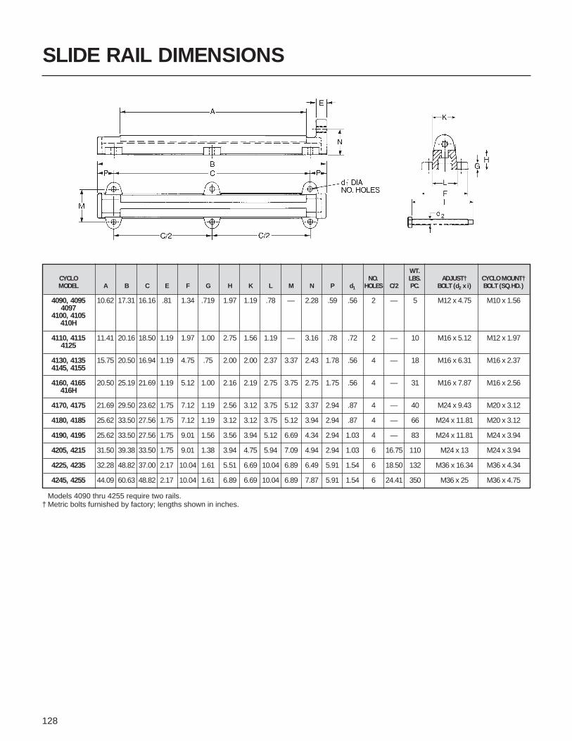
128
SLIDE RAIL DIMENSIONS
WT.CYCLO NO. LBS. ADJUST† CYCLO MOUNT†MODEL A B C E F G H K L M N P d1 HOLES C/2 PC. BOLT (d2 x i) BOLT (SQ.HD.)
4090, 4095 10.62 17.31 16.16 .81 1.34 .719 1.97 1.19 .78 — 2.28 .59 .56 2 — 5 M12 x 4.75 M10 x 1.564097
4100, 4105410H
4110, 4115 11.41 20.16 18.50 1.19 1.97 1.00 2.75 1.56 1.19 — 3.16 .78 .72 2 — 10 M16 x 5.12 M12 x 1.974125
4130, 4135 15.75 20.50 16.94 1.19 4.75 .75 2.00 2.00 2.37 3.37 2.43 1.78 .56 4 — 18 M16 x 6.31 M16 x 2.374145, 4155
4160, 4165 20.50 25.19 21.69 1.19 5.12 1.00 2.16 2.19 2.75 3.75 2.75 1.75 .56 4 — 31 M16 x 7.87 M16 x 2.56416H
4170, 4175 21.69 29.50 23.62 1.75 7.12 1.19 2.56 3.12 3.75 5.12 3.37 2.94 .87 4 — 40 M24 x 9.43 M20 x 3.12
4180, 4185 25.62 33.50 27.56 1.75 7.12 1.19 3.12 3.12 3.75 5.12 3.94 2.94 .87 4 — 66 M24 x 11.81 M20 x 3.12
4190, 4195 25.62 33.50 27.56 1.75 9.01 1.56 3.56 3.94 5.12 6.69 4.34 2.94 1.03 4 — 83 M24 x 11.81 M24 x 3.94
4205, 4215 31.50 39.38 33.50 1.75 9.01 1.38 3.94 4.75 5.94 7.09 4.94 2.94 1.03 6 16.75 110 M24 x 13 M24 x 3.94
4225, 4235 32.28 48.82 37.00 2.17 10.04 1.61 5.51 6.69 10.04 6.89 6.49 5.91 1.54 6 18.50 132 M36 x 16.34 M36 x 4.34
4245, 4255 44.09 60.63 48.82 2.17 10.04 1.61 6.89 6.69 10.04 6.89 7.87 5.91 1.54 6 24.41 350 M36 x 25 M36 x 4.75
Models 4090 thru 4255 require two rails.† Metric bolts furnished by factory; lengths shown in inches.

129
WATER TREATMENTMIXER OPTIONS

ProvenPerformers
Request free catalog & selection guide.SM-CYCLO® Mixer Drives, Agitator Drives andClarifier Drives are designed to endure the tests oftime, hostile environments and shock overloads(500%). Rugged construction, smooth, rolling action of cycloiddiscs and over 5,000,000 installations worldwide have gainedSumitomo SM-CYCLO® speed reducers and gearmotors anunmatched reputation for proven performance and reliability.
We offer a 24-month warranty, very competitive pricing and anational sales, engineering and service organization whichprovides comprehensive, fast and efficient service.

131
TORQUE LIMITER EQUIPPED SM-CYCLO®
Torque Limiter Equipped SM-CYCLO DRIVES areoffered as optional equipment for specific modelsof SM-CYCLO speed reducers and gearmotors.They are torque limiting devices which preventdamage to machinery from overloads and jams,thereby reducing costly downtime.
With torque limiter equipped SM-CYCLO speedreducers, when the reducer or gearmotor outputtorque exceeds a predetermined limit, a microswitch instantly breaks the motor circuit, protectingprocess equipment. These controls can be suppliedfor either one or two directions of rotation.
FEATURESSAFE UNATTENDED OPERATIONReliable Torque Limiter response to overload cuts motorpower automatically, stopping the machine. Thiseliminates costly inspection and repair.
COST AFFECTIVE MACHINE DESIGNThe torque setting on SM-CYCLO equipped with TorqueLimiter is more accurate and reliable when comparedwith conventional Torque Limiters. Consequently, theuse of a lower safety factor on auxiliary equipment maybe considered, which will decrease the cost of the entiresystem.
BI-DIRECTIONAL TORQUE SETTINGNormally, the Torque Limiter is set to limit torquerelative to one direction of slow speed shaft rotation.However, the torque limiter can be set in both directionsupon request.
EASY SET POINT ADJUSTMENTAll calibration levels are factory set. No furtheradjustments are required. If recalibration is desired,simply rotate the adjusting bolt which changes restraintspring load and set point. Adjustment that can be madeis within ±25% of set torque.
ENCLOSED STRUCTUREStructure of the Torque Limiter is enclosed to prevententrance of gas, dust and other environmentalcontaminants.
COMBINATION WITH OTHER PROTECTIVEDEVICESThe Torque Limiter may be connected to another alarmsystem (i.e., buzzer and/or lamp) as an option to warnabout power failure (see example wiring diagram).
HIGH PRECISIONBasic component of the Torque Limiter is a highprecision coil spring. Under load, the spring deflects inproportion to torque. Repeatability of the torque setpoint is ±5% to ±10%.
POSITIVE MECHANICAL OPERATIONReliable safety device at overload.
INSTANTANEOUS RESPONSE TO OVERLOADLess time delay compared with electrical systems.Reaction to corresponding overload is much faster.
SELECTED STARTING TORQUETorque set point can optionally be selected to withstandstart-up torque by by-passing limit switch current.
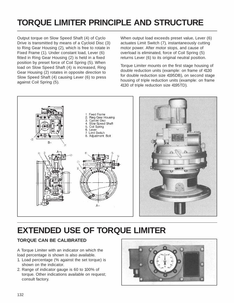
132
TORQUE LIMITER PRINCIPLE AND STRUCTURE
Output torque on Slow Speed Shaft (4) of CycloDrive is transmitted by means of a Cycloid Disc (3)to Ring Gear Housing (2), which is free to rotate inFixed Frame (1). Under constant load, Lever (6)fitted in Ring Gear Housing (2) is held in a fixedposition by preset force of Coil Spring (5). Whenload on Slow Speed Shaft (4) is increased, RingGear Housing (2) rotates in opposite direction toSlow Speed Shaft (4) causing Lever (6) to pressagainst Coil Spring (5).
When output load exceeds preset value, Lever (6)actuates Limit Switch (7), instantaneously cuttingmotor power. After motor stops, and cause ofoverload is eliminated, force of Coil Spring (5)returns Lever (6) to its original neutral position.
Torque Limiter mounts on the first stage housing ofdouble reduction units (example: on frame of 4130for double reduction size 4195DB), on second stagehousing of triple reduction units (example: on frame4130 of triple reduction size 4195TD).
EXTENDED USE OF TORQUE LIMITERTORQUE CAN BE CALIBRATED
A Torque Limiter with an indicator on which theload percentage is shown is also available.1. Load percentage (% against the set torque) is
shown on the indicator.2. Range of indicator gauge is 60 to 100% of
torque. Other indications available on request;consult factory.

133
EXTENDED USE OF TORQUE LIMITER CONT.
TORQUE CAN BE READ ATLOCATIONS AWAY FROM THE REDUCERLoad cell type Torque Limiters contain a transducer asan overload protection device. The transducer servicesreactive load at the SM-CYCLO ring gear housing.Reactive load is converted into an electrical signal (i.e., 4 – 20 ma d.c.) for feedback, control and torqueindication.
EXAMPLE OF WIRING CONNECTION(Consult factory for specific connections.)
INCREASED NUMBER OF CONTACTSDual safety devices using two limit switches areavailable. One limit switch can be set to alarm at atorque less than set torque. The second switch can beset to cut the motor power source at set torque.
AVAILABLE MODELSExplosion proof and underwater models available onrequest. Consult factory.
Note: Limit switches shown by dotted line in the Fig. below are standard in Torque Limiter equipped SM-CYCLO. The parts except for LS to be supplied by customer.
M Motor for SM-CYCLOMC Magnetic motor switch#MC MC coilMCa1 MC auxiliary contact (a contact)MCa2 MC auxiliary contact (b contact)B.L. AlarmF FuseBon Push button operating switchBoff Push button power cut-off switchTR Motor time delay (in case of high
starting torque or large shock)Th Thermal relayLs Limit switchKs Knife switch
Energize motor M by pressing the OPERATION pushbutton (Bon). MCa2 for alarm is in open position at thistime. When torque is excessively increased, limit switchLs activates, MCa1 opens to de-energize the motor and
alarm B.L. enunciates. Anticipated starting time may beextended if starting torque is higher than set torque byinstalling time delay TR.
APPLICATIONSMixer, Stoker, Conveyor, Roll and various other machines.
FOR INQUIRIES NOTE THE FOLLOWING:1. Slow speed shaft normal torque2. Slow speed shaft pre-set torque3. Direction of the slow speed shaft rotation viewed from the shaft side4. Motor input speed and power5. Driven machine6. Load conditions…degree of shock and operating cycles7. SM-CYCLO model and frame size, reduction ratio8. Whether or not dual-direction type is required9. Place of installation: indoor or outdoor
10. Ambient condition: dust, corrosion, explosion

134
HOW TO READJUST PRESET TORQUE
1. All calibration levels are factory set. No furtheradjustments are required.
2. If recalibration is desired, simply rotate the adjustingbolt per the scale .Preset torque is shown on top portion of the scale .T1 and T2 show the torque when the adjusting boltis rotated 150 degrees to C.W. or C.C.W.
3. Adjustment that can be made is within ±25% of currentpreset torque.The adjusting bolt can be rotated more than ±150degrees over the scale (T1 and T2) as long as thetorque is within ±25% of current preset torque.However the readjusted torque should be less thanthe rated output torque or Maximum preset torque inthe selection table.
55
2
2
2

135
TORQUE LIMITER SELECTION
1. SM-CYCLO TORQUE LIMITER is designed for 24-hour daily service underuniform or low fluctuating loads. For selection refer to the Tables 1 to 3(Reduction Ratio 6 through 109,091:1). When the application involvesfrequent start-stop, heavy shock load, consult the factory.
2. “The preset torque” must be less than the rated output torque. However,the preset torque must be less than the number in bracket for the framesize with the bracket in Tables 1 to 3.
3. The selection table is based on 1750 rpm input. Consult the factory wheninput speed is not 1750 rpm.
RATED Reduction6 11 17 29 35 43 59 87
Output RatioTorque Output Speed 292 159 103 60.3 50.0 40.7 29.7 20.1(In-Lbs) (rpm)
Frame Size 4105 4105 4105 4105 4105 4105 4105 4100
1130 Motor HP 2 2 2 1 1 1 1/2 1/4Maximum
Preset Torque378 693 1070 914 1100 [955] [521]
Frame Size 4115 4110 4110 4110 4115 4115 4115 4110
1480 Motor HP 3, 5 3 2 2 2 2 1 1/2Maximum 567, 945 1040 1070 [1300]
Preset TorqueFrame Size 4135 4135 4130 4130 4135 4135 4135 4130
3730Motor HP 71⁄2, 10 5, 71⁄2, 10 3, 5 2, 3 3 3 2 1Maximum 1420, 1890 1730, 2600, 3470 1610, 2680 1830, 2740 3310 [2740]
Preset TorqueFrame Size 4165 4165 4160 4160 4160 4165 4160 4165
7640Motor HP 15, 20 10, 15 71⁄2, 10 5, 71⁄2 5 5 3 3Maximum 2840, 3780 3470, 5200 4020, 5360 4570, 6850 5510 6770 5580
Preset TorqueFrame Size 4175 4170 4175 4170 4170 4170 4170
11700Motor HP 30 20 15, 20 10 71⁄2, 10 71⁄2 5 —Maximum 5670 6930 8030, 10700 9140 8270, 11000 10200 9290
Preset TorqueFrame Size 4180 4180 4180 4180 4180 4180 4185
14800Motor HP — 30 20 15 10 10 71⁄2 71⁄2Maximum 10400 10700 13700 11000 13500 13900
Preset TorqueFrame Size 4195 4195 4195 4190 4195 4195 4195
39100Motor HP — 40 30, 40 20, 30 15, 20 15, 20 10, 15 10Maximum 13900 16100, 21400 18300, 27400 16500, 22100 20300, 27100 18600, 27900 [27500]
Preset Torque
Table 1 (Single Reduction Reducers) Reduction Ratio 6:1 to 87:1 Input Speed 1750 rpm.
NOTE:1. Designation of figures indicated in each frame.
Example
41355, 71⁄2, 10
1730, 2600, 3470
Frame size of SM-CYCLOStandard input HP (input speed 1750 rpm)Each value shows the maximum output torquewhen the above motor is fully loaded.When there is no number, the preset torque isallowed up to the rated output torque shown inthe left frame.The value in the bracket is the torque allowableon the output shaft especially for the reductionratio and the frame size.
2. Selection ExampleGiven Ratio 59:1, Input Speed 1750 rpm, Preset Torque5200 IN. LBS.
Procedure1) Locate the model which satisfies the preset torque 5200
IN. LBS and the ratios 59:1 in the Table. At the cross ofratio 59:1 and Rated Output Torque 7640 IN. LBS,following data is found.
Frame Size 4160Motor HP 3Maximum Preset Torque 5580 IN. LBS
2) 5200 IN. LBS is less than the Maximum Preset Torque,therefore 3 HP is enough for required torque.

136
TORQUE LIMITER SELECTION TABLE
Table 2 (Double Reduction Reducers) Reduction Ratio 66:1 to 7569:1 Input Speed 1750 rpm
RatedReduction 66 90 102 121 165 187 231 289 319 385 473 493 595 649 731
OutputRatio [11x6] [15x6] [17x6] [11x11] [15x11] [17x11] [21x11] [17x17] [29x11] [35x11] [43x11] [29x17] [35x17] [59x11] [43x17]
Torque(in-lbs)
Output Speed26.5 19.4 17.2 14.5 10.6 9.36 7.58 6.06 5.49 4.55 3.70 3.55 2.94 2.70 2.39(rpm)
Frame Size 4135DC 4135DC 4135DC 4135DC 4135DC 4135DC 4135DC 4135DC 4135DC 4135DC 4135DC
6,250 Motor HP 2 1, 2 1, 2 1 1 1 1 1 1/2 1/2 1/2Maximum 5710 3390, 5240,
Preset Torque 6250 6250Frame Size 4160DB 4145DC 4145DC 4145DC 4145DC 4145DC 4145DC 4145DC
7,810 Motor HP 2 1 1 1 1 1 1 1/2Maximum 5710
Preset TorqueFrame Size 4165DC 4165DC 4165DC 4165DB 4165DB 4165DB 4165DB 4165DB 4165DB 4165DB 4165DB
12,500 Motor HP 3, 5 3, 5 3 2 2 1 1 1 1 1 1Maximum 8570, 10200, 10780
Preset Torque 12500 12500Frame Size 4175DC 4175DC 4175DC 4175DB 4175DB 4175DB 4175DB 4175DB 4175DB
21,700 Motor HP 3, 5 3 2, 3 2 2 2 2 2 1Maximum 15700, 17900, 20500
Preset Torque [19100] [2000] 21700Frame Size 4185DB 4185DB 4185DB 4185DB 4185DB 4185DB 4185DB 4185DB 4185DB 4185DA 4185DA 4185DA
31,200 Motor HP 7.5, 10 7.5, 10 7.5 5, 7.5 3, 5 3, 5 3 2, 3 2, 3 2 2 2Maximum 13900, 21400, 25400 26200, 24300, 26800, 26500, 27600,
Preset Torque 18500 26000 31200 31200 31200 31200 31200Frame Size 4205DB 4190DB 4190DB 4190DB 4190DB 4190DB 4190DB 4190DB 4190DB 4190DB 4190DA 4190DA
48,600 Motor HP 10 10 7.5, 10 7.5, 10 5, 7.5 5, 7.5 3, 5 3, 5 3, 5 3, 5 2, 3 2, 3Maximum 25400, 39300, 40500, 44700, 32300, 39700, 41400, 33300, 36300, 40900,
Preset Torque [42500] [46000] [32100] 48600 48600 48600 48600 48600 48600 48600 48600 48600Frame Size 4215DB 4205DB
55,600 Motor HP 15, 20 10Maximum 27700,
Preset Torque 37000 [45600]Frame Size 4215DB 4215DB 4205DB 4195DB 4195DB 4195DB 4195DB 4195DB 4195DA 4195DB
62,500 Motor HP 15, 20 15 7.5, 10 7.5 5, 7.5 5 5 3, 5 3, 5 3Maximum 37800, 50800 48500, 53900, 50,000, 54500, 61400
Preset Torque 50400 62500 62500 62500 62500Frame Size 4225DB 4215DB 4205DB 4205DB 4205DB
72,900 Motor HP 30 15 7.5 5 5Maximum 55400 69300
Preset TorqueFrame Size 4225DB 4225DB 4215DB 4215DA 4215DA
82,500 Motor HP 30 20 10, 15 7.5, 10 5, 7.5Maximum 75600 67900 64700, 67000, 69000,
Preset Torque 82500 82500 82500Frame Size 4235DB 4225DB 4215DA 4215DA 4215DA
95,500 Motor HP 30 15, 20 7.5 5 5Maximum 69300, 90900
Preset Torque 92400Frame Size 4225DB 4225DB 4225DB
108,000 Motor HP 15, 20 10, 15 7.5Maximum 97000, 89300, 104000
Preset Torque 108000 108000Frame Size 4245DB 4235DB 4225DA 4225DA 4225DA
121,000 Motor HP 30 20, 30 7.5, 10 5, 7.5 5, 7.5Maximum 102000 92400, 99300, 90900, 102000,
Preset Torque 121000 121000 121000 121000Frame Size 4235DB 4235DA 4235DA
139,000 Motor HP 20 15 7.5, 10Maximum 129000 134000 104000,
Preset Torque 138000Frame Size 4255DB 4245DB 4235DA 4235DA 4235DA
156,000 Motor HP 40 30 10, 15 7.5, 10 7.5Maximum 136000 139000 132000, 136000, 154000
Preset Torque 156000 156000Frame Size 4245DB 4245DB 4245DA
174,000 Motor HP 20, 30 15, 20 10, 15Maximum 129000, 134000, 138000,
Preset Torque 194000 179000 174000Frame Size 4265DB 4255DB 4245DA 4245DA 4245DA
200,000 Motor HP 40 40 15 10, 15 7.5, 10Maximum 136000 185000 199000 182000, 154000,
Preset Torque 200000 200000Frame Size 4255DB 4255DB 4255DA
226,000 Motor HP 30, 40 20, 30 15Maximum 194000, 179000, 207000
Preset Torque 226000 226000Frame Size 4265DA 4255DA 4255DA 4255DA
260,000 Motor HP 40 15, 20 15 10, 15Maximum 185000 199000, 205000,
Preset Torque 260000 260000Frame Size 4265DA 4265DA 4265DA
304,000 Motor HP 40 30 15, 20Maximum 259000 268000 207000,
Preset Torque 276000Frame Size 4265DA 4265DA 4265DA
347,0000 Motor HP 20, 30 15 15, 20Maximum 260000, 273000 307000,
Preset Torque 347000 347000Frame Size 4275DA 4275DA 4275DA 4275DA 4275DA
521,000 Motor HP 40 30, 40 30, 40 30 20, 30Maximum 357000 397000, 414000, 409000,
Preset Torque 521000 521000 521000
NOTE: 1. DESIGNATION OF FIGURES INDICATED IN EACH FRAME.EXAMPLE 4190DB
7.5, 1025,400,[32,100]
Frame size of SM-CYCLOStandard input HP (input speed 1750 rpm)Each value shows the maximum output torque when the above motor is used.[Above side value for the right side motor HP, lower side value for the left side motor HP]The value in the bracket is the torque allowable on the output shaft especially for the reductionratio and the frame size. When there is no number, the preset torque is allowed up to the ratedoutput torque shown in the left and right frame.

137
841 957 1003 1015 1225 1247 1479 1505 1711 1849 2065 2523 2537 3045 3481 3741 5133 7569 Rated[29x29] [87x11] [59x17] [35x29] [35x35] [43x29] [87x17] [43x35] [59x29] [43x43] [59x35] [87x29] [59x43] [87x35] [59x59] [87x43] [87x59] [87x87] Output
*[43x87] *[59x87] Torque
2.08 1.83 1.74 1.72 1.43 1.40 1.18 1.16 1.02 0.95 0.85 0.69 0.69 0.57 0.50 0.47 0.34 0.23
4135DC 4135DC 4135DC 4135DC 4135DC 4135DC 4135DC 4135DC 4135DC 4135DC 4135DC 4135DC 4135DC 4135DC 4135DC 4135DC 4135DC 4135DC1/2 1/2 1/2 1/2 1/2 1/2 1/2 1/2 1/2 1/2 1/2 1/2 1/2 1/2 1/2 1/2 1/2 1/2 6,250
4145DC 4145DC 4145DC 4145DC 4145DC 4145DC 4145DC 4145DC 4145DC 4145DC 4145DC 4145DC 4145DC 4145DC 4145DC 4145DC 4145DC 4145DC1/2 1/2 1/2 1/2 1/2 1/2 1/2 1/2 1/2 1/2 1/2 1/2 1/2 1/2 1/2 1/2 1/2 1/2
7,810
4165DB 4165DB 4165DB 4165DB 4165DB 4165DB 4165DB 4165DB 4165DB 4165DB 4165DB 4165DB 4165DB 4165DB 4165DB 4165DB 4165DB 4165DB1 1 1/2 1/2 1/2 1/2 1/2 1/2 1/2 1/2 1/2 1/2 1/2 1/2 1/2 1/2 1/2 1/2
12,500
4175DB 4175DB 4175DB 4175DB 4175DB 4175DB 4175DB 4175DB 4175DB 4175DB 4175DB 4175DB 4175DB 4175DB 4175DB 4175DB 4175DB 4175DB1 1 1 1 1 1 1 1 1/2 1/2 1/2 1/2 1/2 1/2 1/2 1/2 1/2 1/2
21,700
4185DB 4185DA 4185DA 4185DA 4185DA 4185DA 4185DA 4185DA 4185DA 4185DA 4185DA 4185DA 4185DA 4185DA 4185DA 4185DA 4185DA 4185DA2 2 1, 2 1, 2 1 1 1 1 1 1 1 1 1 1/2 1/2 1/2 1/2 1/2
26800, 28400, 31,20031200 31200
4190DB 4190DA 4190DA 4190DB 4190DB 4190DA 4190DA 4190DA 4190DA 4190DA 4190DA 4190DA 4190DA 4190DA 4190DA 4190DA 4190DA 4190DA2, 3 2 2 2 2 2 2 2 2 1 1 1 1 1 1 1 1 1
47100, 48,60048600
55,600
4195DB 4195DA 4195DA 4195DB 4195DB 4195DB 4195DA 4195DB 4195DA 4195DB 4195DA 4195DA 4195DA 4195DA 4195DA 4195DA 4195DA 4195DA3 2, 3 2, 3 2, 3 2 2 2 2 2 1 1 1 1 1 1 1 1 1
53600, 56200, 56800, 51800 57800 62,50062500 62500 62500
4205DB 4205DB 4205DB 4205DB 4205DB 4205DB 4205DB 4205DB *4205DB *4205DB3 2 2 2 2 2 2 2 2 2
69800 72,900
4215DA 4215DA 4215DA 4215DA 4215DA 4215DA3, 5 3 2 2 2 2
70600, 80400 82,50082500
4215DA 4215DA 4215DA 4215DA 4215DA 4215DA 4215DA 4215DA *4215DA *4215DA3, 5 2, 3 2, 3 2 2 2 2 2 2 2
84300, 69800, 84300, 95,50095500 95500 95500
4225DB 4225DA 4225DA 4225DA 4225DA 4225DA5 3, 5 2, 3 2 2 2
80400, 82800, 108,000108000 108000
4225DA 4225DA 4225DA 4225DA 4225DA 4225DA 4225DA 4225DA *4225DA *4225DA5 3, 5 3 2, 3 2, 3 2, 3 2 2 2 2
121000 105000, 95800, 104000, 116000, 121,000121000 121000 121000 121000
4235DA 4235DA 4235DA 4235DA 4235DA 4235DA5, 7.5 5, 7.5 3, 5 3 3 3
118000, 134000, 124000, 139,000139000 139000 139000
4235DA 4235DA 4235DA 4235DA 4235DA 4235DA 4235DA 4235DA *4235DA *4235DA5, 7.5 5 3, 5 3, 5 3 3 3 3 3 3
140000, 126000, 144000, 155000 156,000156000 156000 156000
4245DA 4245DA 4245DA 4245DA 4245DA 4245DA7.5 7.5 5 3 3 3
174,000
4245DA 4245DA 4245DA 4245DA 4245DA 4245DA 4245DA 4245DA *4245DA *4245DA7.5 5, 7.5 5 5 3, 5 3, 5 3 3 3 3
175000, 155000, 173000, 200,000200000 200000 200000
4255DA 4255DA 4255DA 4255DA 4255DA 4255DB7.5, 10 7.5, 10 5, 7.5 5 5 7.5
177000, 201000, 207000, 226,000226000 226000 226000
4255DA 4255DA 4255DA 4255DA 4255DA 4255DA 4255DA 4255DA *4255DB *4255DB7.5, 10 7.5 5, 7.5 5, 7.5 5 5 5 5 7.5 7.5211000, 211000, 240000, 259000 260,000260000 260000 260000
4265DA 4265DA 4265DA 4265DA 4265DA 4265DA10, 15 10, 15 7.5 7.5 7.5 7.5
235000, 268000, 304,000304000 304000
4265DA 4265DA 4265DA 4265DA 4265DA 4265DA 4265DA 4265DA *4265DA *4265DA10, 15 7.5, 10 7.5, 10 7.5 7.5 7.5 7.5 7.5 7.5 7.5
281000, 262000, 316000, 347,000347000 347000 347000
4275DA 4275DA 4275DA 4275DA 4275DA 4275DA 4275DA 4275DA 4275DA 4275DA 4275DA 4275DA 4275DA *4275DA *4275DA20, 30 20 20 15 15 10, 15 10, 15 10 10 10 10 10 10 10 10
471000, 421000, 479000, 521,000521000 521000 521000
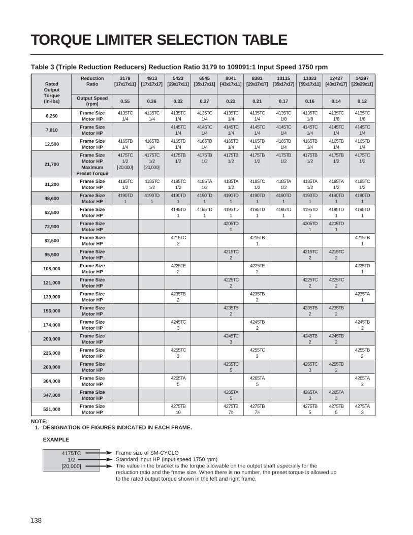
138
TORQUE LIMITER SELECTION TABLE
Table 3 (Triple Reduction Reducers) Reduction Ratio 3179 to 109091:1 Input Speed 1750 rpm
RatedReduction 3179 4913 5423 6545 8041 8381 10115 11033 12427 14297
OutputRatio [17x17x11] [17x17x17] [29x17x11] [35x17x11] [43x17x11] [29x17x17] [35x17x17] [59x17x11] [43x17x17] [29x29x11]
Torque(in-lbs)
Output Speed0.55 0.36 0.32 0.27 0.22 0.21 0.17 0.16 0.14 0.12(rpm)
6,250Frame Size 4135TC 4135TC 4135TC 4135TC 4135TC 4135TC 4135TC 4135TC 4135TC 4135TCMotor HP 1/4 1/4 1/4 1/4 1/4 1/4 1/8 1/8 1/8 1/8
7,810Frame Size 4145TC 4145TC 4145TC 4145TC 4145TC 4145TC 4145TC 4145TCMotor HP 1/4 1/4 1/4 1/4 1/4 1/4 1/4 1/4
12,500Frame Size 4165TB 4165TB 4165TB 4165TB 4165TB 4165TB 4165TB 4165TB 4165TB 4165TBMotor HP 1/4 1/4 1/4 1/4 1/4 1/4 1/4 1/4 1/4 1/4
Frame Size 4175TC 4175TC 4175TB 4175TB 4175TB 4175TB 4175TB 4175TB 4175TB 4175TC
21,700Motor HP 1/2 1/2 1/2 1/2 1/2 1/2 1/2 1/2 1/2 1/2Maximum [20,000] [20,000]
Preset Torque
31,200Frame Size 4185TC 4185TC 4185TC 4185TA 4185TA 4185TC 4185TA 4185TA 4185TA 4185TCMotor HP 1/2 1/2 1/2 1/2 1/2 1/2 1/2 1/2 1/2 1/2
48,600Frame Size 4190TD 4190TD 4190TD 4190TD 4190TD 4190TD 4190TD 4190TD 4190TD 4190TDMotor HP 1 1 1 1 1 1 1 1 1 1
62,500Frame Size 4195TD 4195TD 4195TD 4195TD 4195TD 4195TD 4195TD 4195TDMotor HP 1 1 1 1 1 1 1 1
72,900Frame Size 4205TD 4205TD 4205TDMotor HP 1 1 1
82,500Frame Size 4215TC 4215TB 4215TBMotor HP 2 1 1
95,500Frame Size 4215TC 4215TC 4215TCMotor HP 2 2 2
108,000Frame Size 4225TE 4225TE 4225TDMotor HP 2 2 1
121,000Frame Size 4225TC 4225TC 4225TCMotor HP 2 2 2
139,000Frame Size 4235TB 4235TB 4235TAMotor HP 2 2 1
156,000Frame Size 4235TB 4235TB 4235TBMotor HP 2 2 2
174,000Frame Size 4245TC 4245TB 4245TBMotor HP 3 2 2
200,000Frame Size 4245TC 4245TB 4245TBMotor HP 3 2 2
226,000Frame Size 4255TC 4255TC 4255TBMotor HP 3 3 2
260,000Frame Size 4255TC 4255TC 4255TBMotor HP 5 3 2
304,000Frame Size 4265TA 4265TA 4265TAMotor HP 5 5 2
347,000Frame Size 4265TA 4265TA 4265TAMotor HP 5 3 3
521,000Frame Size 4275TB 4275TB 4275TB 4275TB 4275TB 4275TAMotor HP 10 71⁄2 71⁄2 5 5 3
NOTE:1. DESIGNATION OF FIGURES INDICATED IN EACH FRAME.
EXAMPLE
4175TC1/2
[20,000]
Frame size of SM-CYCLOStandard input HP (input speed 1750 rpm)The value in the bracket is the torque allowable on the output shaft especially for thereduction ratio and the frame size. When there is no number, the preset torque is allowed upto the rated output torque shown in the left and right frame.

139
16269 17051 21199 25143 27907 31433 38291 43129 51765 63597 79507 87261 109091[87x17x11] [59x17x17] [43x29x17] [87x17x17] [59x43x11] [43x43x17] [59x59x11] [59x43x17] [87x35x17] [87x43x17] [43x43x43] [87x59x17] [59x43x43]
*[43x87x17] [59x87x17]
0.11 0.10 0.083 0.070 0.063 0.056 0.046 0.041 0.034 0.028 0.022 0.020 0.016
4135TC 4135TC 4135TC 4135TC 4135TC 4135TC 4135TC 4135TC 4135TC 4135TC 4135TC 4135TC 4135TC1/8 1/8 1/8 1/8 1/8 1/8 1/8 1/8 1/8 1/8 1/8 1/8 1/8
4145TC 4145TC 4145TC 4145TC 4145TC 4145TC 4145TC 4145TC 4145TC 4145TC 4145TC 4145TC 4145TC1/4 1/8 1/8 1/8 1/8 1/8 1/8 1/8 1/8 1/8 1/8 1/8 1/8
4165TB 4165TB 4165TB 4165TB 4165TB 4165TB 4165TB 4165TB 4165TB 4165TB 4165TB 4165TB 4165TB1/4 1/4 1/4 1/4 1/4 1/4 1/8 1/8 1/8 1/8 1/8 1/8 1/8
4175TB 4175TB 4175TB 4175TB 4175TB 4175TB 4175TB 4175TB 4175TB 4175TB 4175TB 4175TB 4175TB
1/2 1/4 1/4 1/4 1/4 1/4 1/4 1/4 1/4 1/4 1/4 1/4 1/4
4185TA 4185TA 4185TA 4185TA 4185TA 4185TA 4185TA 4185TA 4185TA 4185TA 4185TA 4185TA 4185TA1/2 1/2 1/2 1/4 1/4 1/4 1/4 1/4 1/4 1/4 1/4 1/4 1/4
4190TD 4190TA 4190TA 4190TA 4190TA 4190TA 4190TA 4190TA 4190TA 4190TA 4190TA 4190TA 4190TA1 1/2 1/2 1/2 1/2 1/2 1/2 1/2 1/2 1/2 1/4 1/4 1/4
4195TD 4195TA 4195TC 4195TA 4195TA 4195TD 4195TA 4195TA 4195TA 4195TA 4195TD 4195TA 4195TA1 1/2 1/2 1/2 1/2 1/2 1/2 1/2 1/2 1/2 1/4 1/4 1/4
4205TD 4205TD 4205TD 4205TD 4205TD 4205TD *4205TD 4205TD *4205TD 4205TD1 1/2 1/2 1/2 1/2 1/2 1/2 1/2 1/2 1/2
4215TB 4215TB 4215TB1 1/2 1/2
4215TB 4215TB 4215TB 4215TB 4215TB 4215TB *4215TB 4215TB *4215TB 4215TB1 1 1/2 1/2 1/2 1/2 1/2 1/2 1/2 1/2
4225TB 4225TB 4225TB1 1 1/2
4225TB 4225TB 4225TB 4225TB 4225TB 4225TB *4225TB 4225TB *4225TB 4225TB1 1 1 1 1/2 1/2 1/2 1/2 1/2 1/2
4235TA 4235TA 4235TA1 1 1/2
4235TA 4235TA 4235TA 4235TA 4235TA 4235TA *4235TA 4235TA *4235TA 4235TA1 1 1 1 1 1/2 1/2 1/2 1/2 1/2
4245TB 4245TA 4245TA2 1 1/2
4245TB 4245TB 4245TB 4245TA 4245TA 4245TA *4245TA 4245TA *4245TA 4245TA2 2 2 1 1 1 1/2 1/2 1/2 1/2
4255TB 4255TB 4255TA2 2 1
4255TB 4255TB 4255TB 4255TA 4255TA 4255TA *4255TD 4255TA *4255TD 4255TA2 2 2 2 1 1 1 1/2 1 1/2
4265TA 4265TA 4265TA2 2 1
4265TA 4265TA 4265TA 4265TA 4265TA 4265TA *4265TA 4265TA *4265TA 4265TA2 2 2 2 2 2 1 1 1 1
4275TA 4275TA 4275TA 4275TA 4275TA 4275TA 4275TA 4275TA 4275TA 4275TA 4275TA 4275TA3 3 3 3 2 2 2 2 2 1 1 1
2. SELECTION EXAMPLEGiven Ratio 12427:1, Input Speed 1750 rpm, Preset Torque 28,600 IN-LBS.
Procedure*Locate the model which satisfies the preset torque 28,600 IN-LBS and the ratio 12427:1 in the table.At the cross of ratio 12427:1 and Rated Output Torque 31200 IN-LBS, following data is found.Frame Size 4185TAMotor HP 1/2 HP

140
TORQUE LIMITER DIMENSIONS
HORIZONTAL SPEED REDUCERS / TYPE H, SINGLE REDUCTION
LOW SPEED SHAFT HIGH SPEED SHAFTMODEL A B C D E F G H J O P S Y BW
U V KEY XU XV
H4100-TL7.87 5.31 8.19 4.409 3.35 3.54 0.47 0.43 1.77 12.28 7.17 -2.09 11.73 2.36 1.125 1.38 1⁄4 x 1⁄4 x 1.18 0.625 0.98H4105-TL
H4110-TL11.0 7.09 10.2 5.512 4.72 5.51 0.59 0.55 2.17 14.21 9.45 -1.18 11.73 3.23 1.500 2.17 3⁄8 x 3⁄8 x 1.77 0.750 1.38H4115-TL
H4130-TL14.2 8.66 12.6 6.299 6.30 6.69 0.87 0.71 2.56 16.18 10.43 -0.51 13.07 3.94 1.875 2.76 1⁄2 x 1⁄2 x 2.17 0.875 1.57H4135-TL
H4160-TL17.3 11.4 16.3 7.874 7.87 8.27 0.98 0.71 2.95 19.45 14.57 0.71 15.43 5.47 2.250 3.54 1⁄2 x 1⁄2 x 2.95 1.125 1.77H4165-TL
H4170-TL19.3 13.2 18.8 9.843 8.66 10.83 1.18 0.87 2.52 23.54 16.30 1.77 18.35 4.92 2.750 3.54 5⁄8 x 5⁄8 x 3.15 1.375 2.17H4175-TL
H4180-TL20.9 15.0 20.7 10.433 9.45 12.60 1.18 0.87 3.54 24.92 18.74 2.01 18.35 5.71 3.125 4.33 3⁄4 x 3⁄4 x 3.74 1.500 2.56H4185-TL
H4190-TL26.8 17.3 24.4 13.189 12.20 14.96 1.38 1.02 4.33 31.69 22.52 3.07 24.65 6.69 3.625 5.31 7⁄8 x 7⁄8 x 4.92 1.750 2.76H4195-TL
KEY
3⁄16 x 3⁄16 x 0.75 55
3⁄16 x 3⁄16 x 1.02 88
3⁄16 x 3⁄16 x 1.38 152
1⁄4 x 1⁄4 x 1.77 260
5⁄16 x 5⁄16 x 2.17 409
3⁄8 x 3⁄8 x 2.56 499
3⁄8 x 3⁄8 x 2.76 957
APPROX.WT.LBS.
NOTES: 1. NEMA C Face Adaptor available2. Gear Motor Type available3. Vertical Type available4. All dimensions in inches5. Shaft Tolerance +.000
-.0016. Mounting dimensions are different
from the ones of Standard Cyclo.

141
HORIZONTAL SPEED REDUCERS / TYPE H, DOUBLE REDUCTION
LOW SPEED SHAFT HIGH SPEED SHAFTMODEL A B C D E F G H J O P S Y BW
U V KEY XU XV
H4135DC-TL 12.99 7.68 14.53 5.906 5.71 5.71 0.87 0.71 2.56 13.78 9.06 2.09 11.73 3.94 1.875 2.76 1⁄2 x 1⁄2 x 2.17 0.625 0.98
H4145DC-TL 12.99 7.68 15.31 5.906 5.71 5.71 0.87 0.71 2.56 13.78 9.06 2.09 11.73 4.72 1.875 3.54 1⁄2 x 1⁄2 x 2.95 0.625 0.98
H4160DB-TL16.14 9.37 17.28 6.299 7.28 5.91 0.98 0.71 2.95 14.17 11.81 2.09 11.73 5.47 2.250 3.54 1⁄2 x 1⁄2 x 2.95 0.625 0.98H4165DB-TL
H4165DC-TL 16.14 9.37 18.19 6.299 7.28 5.91 0.98 0.71 2.95 15.00 11.81 1.18 11.73 5.47 2.250 3.54 1⁄2 x 1⁄2 x 2.95 0.750 1.38
H4175DB-TL 16.93 13.19 19.06 7.874 7.48 10.83 1.18 0.87 2.52 15.75 13.39 2.09 11.73 4.92 2.750 3.54 5⁄8 x 5⁄8 x 3.15 0.750 0.98
H4175DC-TL 16.93 13.19 20.04 7.874 7.48 10.83 1.18 0.87 2.52 16.57 13.39 1.18 11.73 4.92 2.750 3.54 5⁄8 x 5⁄8 x 3.15 0.625 1.38
H4185DA-TL 18.50 14.96 20.71 8.661 8.27 12.60 1.18 0.87 2.87 16.53 14.57 2.09 11.73 5.71 3.125 4.33 3⁄4 x 3⁄4 x 3.74 0.625 0.98
H4185DB-TL 18.50 14.96 22.72 8.661 8.27 12.60 1.18 0.87 2.87 18.54 14.57 0.51 12.68 5.71 3.125 4.33 3⁄4 x 3⁄4 x 3.74 0.875 1.57
H4190DA-TL20.87 17.32 24.76 9.843 9.45 14.96 1.38 1.02 3.54 18.54 16.93 1.18 13.07 6.69 3.625 5.31 7⁄8 x 7⁄8 x 4.92 0.750 1.38H4195DA-TL
H4190DB-TL20.87 17.32 25.71 9.843 9.45 14.96 1.38 1.02 3.54 19.72 16.93 0.51 13.07 6.69 3.625 5.31 7⁄8 x 7⁄8 x 4.92 0.875 1.57H4195DB-TL
H4205DB-TL 20.87 17.32 27.76 9.843 8.66 14.17 1.38 1.02 3.94 19.72 17.64 0.51 13.07 8.46 3.875 6.50 1 x 1 x 6.50 0.875 1.57
H4215DA-TL 22.83 18.70 28.78 10.433 9.45 15.55 1.57 1.02 4.33 20.31 19.06 0.51 13.07 8.27 4.250 6.50 1 x 1 x 6.50 0.875 1.57
H4215DB-TL 22.83 18.70 30.71 10.433 9.45 15.55 1.57 1.02 4.33 22.00 19.06 -0.71 15.43 8.27 4.250 6.50 1 x 1 x 6.50 1.125 1.77
H4225DA-TL 24.41 20.47 30.43 11.024 10.63 16.54 1.57 1.30 4.53 20.91 20.71 0.51 13.07 9.06 4.625 6.50 11⁄4 x 7⁄8 x 6.50 0.875 1.57
H4225DB-TL 24.41 20.47 33.86 11.024 10.63 16.54 1.57 1.30 4.53 24.72 20.71 -1.77 18.35 9.06 4.625 6.50 11⁄4 x 7⁄8 x 6.50 1.375 2.17
H4235DA-TL 26.38 22.05 34.76 11.811 11.42 18.11 1.77 1.30 4.72 23.39 22.13 -0.71 15.43 10.24 5.000 7.87 11⁄4 x 7⁄8 x 7.87 1.125 1.77
H4235DB-TL 26.38 22.05 36.93 11.811 11.42 18.11 1.77 1.30 4.72 26.30 22.13 -2.28 18.35 10.24 5.000 7.87 11⁄4 x 7⁄8 x 7.87 1.500 2.56
H4245DA-TL 28.35 22.83 36.26 13.189 12.40 18.90 1.77 1.54 5.04 24.76 24.17 -0.71 15.43 10.35 5.500 7.87 11⁄4 x 7⁄8 x 7.87 1.125 1.77
H4245DB-TL 28.35 22.83 38.39 13.189 12.40 18.90 1.77 1.54 5.04 27.68 24.17 -2.28 18.35 10.35 5.500 7.87 11⁄4 x 7⁄8 x 7.87 1.500 2.56
H4255DA-TL 30.71 24.80 42.56 14.764 13.19 20.47 1.97 1.54 5.51 28.46 26.38 -1.77 18.35 12.60 6.250 9.45 11⁄2 x 1 x 9.45 1.375 2.17
H4255DB-TL 30.71 24.80 44.61 14.764 13.19 20.47 1.97 1.54 5.51 33.27 26.38 -3.07 24.65 12.60 6.250 9.45 11⁄2 x 1 x 9.45 1.750 2.76
H4265DA-TL 34.65 27.56 48.94 15.748 15.16 23.23 2.17 1.77 6.30 34.25 28.98 -3.07 24.65 15.35 6.625 11.81 13⁄4 x 11⁄4 x 11.8 1.750 2.76
H4275DA-TL 45.67 40.94 59.21 21.260 20.67 *16.54 2.36 1.77 7.87 39.76 37.40 -3.07 24.65 19.09 7.000 13.00 13⁄4 x 11⁄4 x 13 1.750 2.76
KEY
3⁄16 x 3⁄16 x 0.75 130
3⁄16 x 3⁄16 x 0.75 130
3⁄16 x 3⁄16 x 0.75 220
3⁄16 x 3⁄16 x 1.02 242
3⁄16 x 3⁄16 x 0.75 288
3⁄16 x 3⁄16 x 1.02 306
3⁄16 x 3⁄16 x 0.75 374
3⁄16 x 3⁄16 x 1.38 438
3⁄16 x 3⁄16 x 1.02 603
3⁄16 x 3⁄16 x 1.38 653
3⁄16 x 3⁄16 x 1.38 832
1⁄4 x 1⁄4 x 1.77 906
3⁄16 x 3⁄16 x 1.38 997
5⁄16 x 5⁄16 x 2.17 1190
1⁄4 x 1⁄4 x 1.77 1285
3⁄8 x 3⁄8 x 2.56 1434
1⁄4 x 1⁄4 x 1.77 1522
3⁄8 x 3⁄8 x 2.56 1663
5⁄16 x 5⁄16 x 2.17 2365
3⁄8 x 3⁄8 x 2.76 2794
3⁄8 x 3⁄8 x 2.76 3355
3⁄8 x 3⁄8 x 2.76 5863
APPROX.WT.LBS.
NOTES: 1. NEMA C Face Adaptor available2. Gear Motor Type available3. Vertical Type available4. All dimensions in inches5. Shaft Tolerance +.000
-.001
3⁄16 x 3⁄16 x 1.02 565

142
CLARIFIER DRIVE SELECTION TABLE
Triple Reduction Ratio 3179 to 109091:1 Input Speed 1750 rpm
NOTE:1. DESIGNATION OF FIGURES INDICATED IN EACH FRAME.
EXAMPLE
4175TC1/2
[20,000]
Frame size of SM-CYCLOStandard input HP (input speed 1750 rpm)The value in the bracket is the torque allowable on the output shaft especially for thereduction ratio and the frame size. When there is no number, the preset torque is allowed upto the rated output torque shown in the left and right frame.
RatedReduction 3179 4913 5423 6545 8041 8381 10115 11033 12427 14297
OutputRatio [17x17x11] [17x17x17] [29x17x11] [35x17x11] [43x17x11] [29x17x17] [35x17x17] [59x17x11] [43x17x17] [29x29x11]
Torque(in-lbs)
Output Speed0.55 0.36 0.32 0.27 0.22 0.21 0.17 0.16 0.14 0.12(rpm)
6,250Frame Size 4135TC 4135TC 4135TC 4135TC 4135TC 4135TC 4135TC 4135TC 4135TC 4135TCMotor HP 1/4 1/4 1/4 1/4 1/4 1/4 1/8 1/8 1/8 1/8
7,810Frame Size 4145TC 4145TC 4145TC 4145TC 4145TC 4145TC 4145TC 4145TCMotor HP 1/4 1/4 1/4 1/4 1/4 1/4 1/4 1/4
12,500Frame Size 4165TB 4165TB 4165TB 4165TB 4165TB 4165TB 4165TB 4165TB 4165TB 4165TBMotor HP 1/4 1/4 1/4 1/4 1/4 1/4 1/4 1/4 1/4 1/4
Frame Size 4175TC 4175TC 4175TB 4175TB 4175TB 4175TB 4175TB 4175TB 4175TB 4175TC
21,700Motor HP 1/2 1/2 1/2 1/2 1/2 1/2 1/2 1/2 1/2 1/2Maximum [20,000] [20,000]
Preset Torque
31,200Frame Size 4185TC 4185TC 4185TC 4185TA 4185TA 4185TC 4185TA 4185TA 4185TA 4185TCMotor HP 1/2 1/2 1/2 1/2 1/2 1/2 1/2 1/2 1/2 1/2
48,600Frame Size 4190TD 4190TD 4190TD 4190TD 4190TD 4190TD 4190TD 4190TD 4190TD 4190TDMotor HP 1 1 1 1 1 1 1 1 1 1
62,500Frame Size 4195TD 4195TD 4195TD 4195TD 4195TD 4195TD 4195TD 4195TDMotor HP 1 1 1 1 1 1 1 1
72,900Frame Size 4205TD 4205TD 4205TDMotor HP 1 1 1
82,500Frame Size 4215TC 4215TB 4215TBMotor HP 2 1 1
95,500Frame Size 4215TC 4215TC 4215TCMotor HP 2 2 2
108,000Frame Size 4225TE 4225TE 4225TDMotor HP 2 2 1
121,000Frame Size 4225TC 4225TC 4225TCMotor HP 2 2 2
139,000Frame Size 4235TB 4235TB 4235TAMotor HP 2 2 1
156,000Frame Size 4235TB 4235TB 4235TBMotor HP 2 2 2
174,000Frame Size 4245TC 4245TB 4245TBMotor HP 3 2 2
200,000Frame Size 4245TC 4245TB 4245TBMotor HP 3 2 2
226,000Frame Size 4255TC 4255TC 4255TBMotor HP 3 3 2
260,000Frame Size 4255TC 4255TC 4255TBMotor HP 5 3 2
304,000Frame Size 4265TA 4265TA 4265TAMotor HP 5 5 2
347,000Frame Size 4265TA 4265TA 4265TAMotor HP 5 3 3
521,000Frame Size 4275TB 4275TB 4275TB 4275TB 4275TB 4275TAMotor HP 10 71⁄2 71⁄2 5 5 3

143
16269 17051 21199 25143 27907 31433 38291 43129 51765 63597 79507 87261 109091[87x17x11] [59x17x17] [43x29x17] [87x17x17] [59x43x11] [43x43x17] [59x59x11] [59x43x17] [87x35x17] [87x43x17] [43x43x43] [87x59x17] [59x43x43]
*[43x87x17] [59x87x17]
0.11 0.10 0.083 0.070 0.063 0.056 0.046 0.041 0.034 0.028 0.022 0.020 0.016
4135TC 4135TC 4135TC 4135TC 4135TC 4135TC 4135TC 4135TC 4135TC 4135TC 4135TC 4135TC 4135TC1/8 1/8 1/8 1/8 1/8 1/8 1/8 1/8 1/8 1/8 1/8 1/8 1/8
4145TC 4145TC 4145TC 4145TC 4145TC 4145TC 4145TC 4145TC 4145TC 4145TC 4145TC 4145TC 4145TC1/4 1/8 1/8 1/8 1/8 1/8 1/8 1/8 1/8 1/8 1/8 1/8 1/8
4165TB 4165TB 4165TB 4165TB 4165TB 4165TB 4165TB 4165TB 4165TB 4165TB 4165TB 4165TB 4165TB1/4 1/4 1/4 1/4 1/4 1/4 1/8 1/8 1/8 1/8 1/8 1/8 1/8
4175TB 4175TB 4175TB 4175TB 4175TB 4175TB 4175TB 4175TB 4175TB 4175TB 4175TB 4175TB 4175TB1/2 1/4 1/4 1/4 1/4 1/4 1/4 1/4 1/4 1/4 1/4 1/4 1/4
4185TA 4185TA 4185TA 4185TA 4185TA 4185TA 4185TA 4185TA 4185TA 4185TA 4185TA 4185TA 4185TA1/2 1/2 1/2 1/4 1/4 1/4 1/4 1/4 1/4 1/4 1/4 1/4 1/4
4190TD 4190TA 4190TA 4190TA 4190TA 4190TA 4190TA 4190TA 4190TA 4190TA 4190TA 4190TA 4190TA1 1/2 1/2 1/2 1/2 1/2 1/2 1/2 1/2 1/2 1/4 1/4 1/4
4195TD 4195TA 4195TC 4195TA 4195TA 4195TD 4195TA 4195TA 4195TA 4195TA 4195TD 4195TA 4195TA1 1/2 1/2 1/2 1/2 1/2 1/2 1/2 1/2 1/2 1/4 1/4 1/4
4205TD 4205TD 4205TD 4205TD 4205TD 4205TD *4205TD 4205TD *4205TD 4205TD1 1/2 1/2 1/2 1/2 1/2 1/2 1/2 1/2 1/2
4215TB 4215TB 4215TB1 1/2 1/2
4215TB 4215TB 4215TB 4215TB 4215TB 4215TB *4215TB 4215TB *4215TB 4215TB1 1 1/2 1/2 1/2 1/2 1/2 1/2 1/2 1/2
4225TB 4225TB 4225TB1 1 1/2
4225TB 4225TB 4225TB 4225TB 4225TB 4225TB *4225TB 4225TB *4225TB 4225TB1 1 1 1 1/2 1/2 1/2 1/2 1/2 1/2
4235TA 4235TA 4235TA1 1 1/2
4235TA 4235TA 4235TA 4235TA 4235TA 4235TA *4235TA 4235TA *4235TA *4235TA1 1 1 1 1 1/2 1/2 1/2 1/2 1/2
4245TB 4245TA 4245TA2 1 1/2
4245TB 4245TB 4245TB 4245TA 4245TA 4245TA *4245TA 4245TA *4245TA 4245TA2 2 2 1 1 1 1/2 1/2 1/2 1/2
4255TB 4255TB 4255TA2 2 1
4255TB 4255TB 4255TB 4255TA 4255TA 4255TA *4255TD 4255TA *4255TD 4255TA2 2 2 2 1 1 1 1/2 1 1/2
4265TA 4265TA 4265TA2 2 1
4265TA 4265TA 4265TA 4265TA 4265TA 4265TA *4265TA 4265TA *4265TA 4265TA2 2 2 2 2 2 1 1 1 1
4275TA 4275TA 4275TA 4275TA 4275TA 4275TA 4275TA 4275TA 4275TA 4275TA 4275TA 4275TA3 3 3 3 2 2 2 2 2 1 1 1
2. SELECTION EXAMPLEGiven Ratio 12427:1, Input Speed 1750 rpm, Preset Torque 28,600 IN-LBS.
Procedure*Locate the model which satisfies the preset torque 28,600 IN-LBS and the ratio 12427:1 in the table.At the cross of ratio 12427:1 and Rated Output Torque 31200 IN-LBS, following data is found.Frame Size 4185TAMotor HP 1/2 HP

144
NO.MODEL A B G H OF M P X AH Y
HOLES U V KEY
VM4135TC-TL 3.00 2.401⁄2 x 1⁄2
7.8692x 2.17
10.24 7.8720 0.59 0.43 6 0.16 7.87 9.06 11.73 1.875VM4145TC-TL 3.78 3.19
1⁄2 x 1⁄2x 2.95
10.6245 1⁄2 x 1⁄2VM4165TB-TL 13.39
10.62770.79 0.43 6 3.50 0.16 7.87 12.20 11.73 2.250 3.15
x 2.95
7.87 11.73VM4175TB-TL 12.4350 5⁄8 x 5⁄8
15.75 12.4385 0.87 0.55 8 3.70 0.20 14.17 2.750 3.31 x 3.15VM4175TC-TL 8.70 11.73
VM4185TA-TL 13.5768 7.87 11.73 3⁄4 x 3⁄416.93 13.5803 0.87 0.71 8 4.33 0.20 15.35 3.125 3.94 x 3.74
VM4185TC-TL 9.88 13.07
VM4190TA-TL 8.70 11.73
VM4190TD-TL 9.88 13.07
VM4195TA-TL 19.29 15.7421 1.18 0.71 12 5.71 0.24 8.70 17.72 11.73 3.625 4.92 7⁄8 x 7⁄815.7456 x 4.92
VM4195TD-TL 9.88 13.07
VM4205TD-TL 17.91 13.9704 1.18 0.87 8 8.03 0.20 9.88 15.94 13.07 3.875 6.50 1 x 113.9739 x 6.50
VM4215TB-TL 19.29 15.3884 1.38 0.94 8 8.00 0.28 9.88 17.32 13.07 4.250 6.50 1 x 115.3519 x 6.50
VM4225TB-TL
VM4225TC-TL 21.06 16.3321 1.38 1.06 8 8.27 0.39 9.88 18.70 13.07 4.625 6.50 11⁄4 x 7⁄816.3359 x 6.50VM4225TD-TL 13.66 18.35VM4225TD-TL
VM4235TA-TL 22.44 17.7100 1.57 1.06 8 9.84 0.39 11.57 20.08 15.43 5.000 7.87 11⁄4 x 7⁄817.7139 x 6.50VM4235TB-TL
VM4245TA-TL 25.00 19.0880 1.57 1.30 8 9.84 0.39 11.57 22.05 15.43 5.500 7.87 11⁄4 x 7⁄819.0918 x 7.87VM4245TB-TL
VM4245TC-TL
VM4255TA-TL
VM4255TB-TL 26.97 21.0557 1.77 1.30 8 11.61 0.39 13.66 24.02 18.35 6.250 9.45 11⁄2 x 121.0600 x 9.45
VM4255TC-TL
VM4255TD-TL 18.50 24.65
VM4265TA-TL 29.43 22.4337 1.97 1.54 8 14.17 0.39 18.50 25.98 24.65 6.625 11.81 13⁄4 x 11⁄422.4380 x 11.80
CLARIFIER DRIVE DIMENSIONS
Vertical Gearmotor/Type VM, Triple Reduction
APPROX.HORSE C MP AB L α WT.POWER (LBS.)
1⁄8 21.06 4.69 6.46 3.07 1451⁄4 22.13 5.20 6.46 3.98 1471⁄8 21.85 4.69 6.46 3.07
45°145
1⁄4 22.91 5.20 6.46 3.98 1471⁄8 23.82 4.69 6.46 3.07 2271⁄4 24.88 5.20 6.46 3.98
45°229
1⁄4 26.65 5.20 6.46 3.98 3081⁄2 27.44 5.20 6.46 4.37 45° 3101⁄4 27.80 5.20 6.46 3.98 3341⁄4 28.31 5.20 6.46 3.98 3761⁄2 29.09 5.20 6.46 4.37 45° 3781⁄2 30.55 5.20 6.46 4.37 4491⁄4 31.73 5.20 6.46 3.98 5611⁄2 32.52 5.20 6.46 4.37
45°563
1 34.76 5.94 6.57 5.36 0° 6141⁄4 31.73 5.20 6.46 3.98 5611⁄2 32.52 5.20 6.46 4.37 5631⁄4 32.76 5.20 6.46 3.98
45°598
1⁄2 33.54 5.20 6.46 4.37 6031 34.76 5.94 6.57 5.36 0° 6141⁄2 35.55 5.20 6.46 4.37 45° 6491 36.77 5.94 6.57 5.36 0° 6601⁄2 36.61 5.20 6.46 4.37 45° 7811 37.83 5.94 6.57 5.36 7922 39.09 6.85 7.05 5.71
0°807
1⁄2 38.27 5.20 6.46 4.37 45° 9771 39.49 5.94 6.57 5.36 9882 40.75 6.85 7.05 5.71 10031 41.26 5.94 6.57 5.36
0°1177
2 42.52 6.85 7.05 5.71 11921⁄2 41.73 5.20 6.46 4.37 45° 12231 42.95 5.94 6.57 5.36 12342 44.21 6.85 7.05 5.71
0°1250
1⁄2 43.19 5.20 6.46 4.37 45° 14301 44.41 5.94 6.57 5.36 14412 45.71 6.85 7.05 5.71 0° 14563 47.44 6.85 7.05 6.50 14851⁄2 48.70 5.20 6.46 4.37 45° 21961 49.92 5.94 6.57 5.36 22112 51.22 6.85 7.05 5.71 22223 53.07 6.85 7.05 6.50 22555 53.86 8.39 7.76 6.99 22771 51.93 5.94 6.57 5.36 0° 26401 56.26 5.94 6.57 5.36 32342 57.01 6.85 7.05 5.71 32453 58.58 6.85 7.05 6.50 32565 59.33 8.39 7.76 6.99 3278
MOTOR (1750 RPM)
NOTES:1. Conduit box dimension (AB) is for weatherproof motors.
Conduit box dimension (AB) of the standard motor is slightly less.2. NEMA C Face Adaptor available3. Horizontal Type available
4. All dimensions in inches+ 0.000
5. Shaft tolerance - 0.001
LOW SPEED SHAFT

145
VERTICAL GEAR MOTOR/TYPE VM, TRIPLE REDUCTION
SPECIFICATION1. MOTOR - Totally enclosed fan
cooled, 3 phase induction motor,NEMA CLASS B design.AVAILABLE VOLTAGEStandard voltage 230/460V, 60 HzOptional voltage 575V, 60 Hz
220/380V, 50 Hz2. Lubrication: Grease

146
CLARIFIER DRIVE LUBRICATION
For Triple Reduction Cyclo Reducer (Grease Lubricated Unit)
Lubrication for triple reduction Cyclo Reducer:1. Lubrication method..................................grease lubricated2. Standard grease......................................Shell Alvania #2
(-5°F - 122°F)
Maintenance1. Grease replenishment and change interval
Less than 10 hrs. per day Every 3 - 6 monthsReplenishment
10 - 24 hrs. per day Every 500 - 1000 hours
Speed reduction mechanism Every 2 - 3 yearsChange
Slow speed shaft bearings Every 3 - 5 years
2. Grease replenishment and change procedurea. Replenishment
• Remove the grease purge at the vertical case, and then replenish the greasethrough the grease fitting at the high speed end shield or flange of motor byusing the grease gun.
• Replenish the grease while running in order for grease to be distributed well.
• Replenish grease to the reduction mechanism 1/3 to 1/2 of quantities for the firstreduction stage (see Table 1).
b. Change
• When the unit is disassembled for overhauling, refill grease in quantitiesindicated in Table 1 or, alternatively, 80% of the space around reductionmechanism and slow speed shaft bearings of single reduction units and 50%around reduction mechanism of first, second and third stage of triple reductionunits.Apply grease liberally to the central part (i.e., around the eccentric bearings) ofthe mechanism. Apply grease to both the slow speed and high speed shaftbearings as you would do to ordinary bearings at time of re-assembly.
NOTE:If excessive grease is added, agitation heating of the grease will raise the operating temperature ofthe unit. Avoid excessive greasing; however, as the reverse case, when the grease is insufficient itwill raise the operating temperature due to the breakdown of the lubrication films on the eccentricbearing.

147
Table 1 - Quantities of Grease (Ounces)
FRAMESPEED REDUCTION SPEED REDUCTION SPEED REDUCTION SLOW SPEED SHAFT
SIZEMECHANISM MECHANISM MECHANISM BEARING
(FIRST STAGE) (SECOND STAGE) (THIRD STAGE) (THIRD STAGE)
4135TC15.9
4145TC3.5
10.6
4165TB0.7
26.5
4175TB35.3 17.6
4175TC 8.5
4185TA 3.5
4185TC 1.4 15.938.8 21.2
4190TA 0.7 8.5
4190TD 1.4 15.9
4195TA 0.7 8.5 52.9 24.7
4195TD
4205TD 1.4
4215TB15.9 70.5 28.2
4215TC 2.3
4225TB 1.4
4225TC 2.388.2 31.7
4225TD 1.435.3
4225TE 2.3
4235TA 1.4141.0 35.3
4235TB 2.3
4245TA 1.4 26.5
4245TB 2.3 158.7 38.8
4245TC 5.3
4255TA 1.4
4255TB 2.3 35.3211.6 42.3
4255TC
4255TD 5.35.29
4265TA 282.2 45.9

148
SPECIAL BASE MOUNT SM-CYCLO DRIVE®
The 14V and 17V Series SM-CYCLO DRIVES aredesigned especially for applications such as agitator,mixer and reaction vessel drives in water treatment,chemical, pharmaceutical and food industries. The 17VSeries is particularly suited for the drives of aerators.This series has a design that can be readily installed ontanks and/or vessels prepared by the users.
FEATURES: BENEFITS1. EASY INSTALLATIONIn the basic design of this series the SM-CYCLODRIVE slow speed side is directly connected with thespecial lantern (vertical base) for the mixer shaft.
All the SM-CYCLO DRIVE advantages of highefficiency, compact size, robust and long life, and lownoise level are included in this series.
2. SIMPLE DESIGNThe electric motor, SM-CYCLO DRIVE, and the verticalbase are coaxially arranged, making a total configura-tion that is simple and easily accessible.
3. SIMPLE SHAFT CONNECTIONThe mixing operation can be started by simplyconnecting to the mixer shaft.
4. LOW MAINTENANCERadial and thrust bearings are grease lubricated forease of maintenance.
STANDARD SERIESSM-CYCLO DRIVES with special base mount designedfor mixer/agitator work are available in the two standardseries as illustrated below:
14VThis series has a shortervertical base than the 17Vmaking it more suitablefor applications wherethe distance to the mixerblade is relatively short orfor thinner liquid mixing.
17VThe extension shaft andSM-CYCLO DRIVE slowspeed shaft are rigidlyconnected. Theextension shaft issupported by twobearings at the verticalbase (lantern).

149
CYCLO DRIVE® BENDING MOMENTSAND THRUST CAPACITIES
14V Specifications
THRUSTBENDING LOAD
MODEL MOMENT CAPACITY(LB. FT.)1 (LBS.)2 X Y
4090/5/74100/5/H 255 220 7.48 .85
4110/54125 470 375 9.45 .89
4130/54145 800 600 11.81 1.064155
4160/5 1160 840 13.78 1.18
4170/5 1670 1100 15.75 1.14
4180/5 2170 1400 17.72 1.28
4190/5 2820 1720 19.69 1.36
BEARING SPAN(IN INCHES)
NOTE:1. Bending Moment is at the mounting surface.
2. Both upward or downward thrust loads can be supported.
Consult factory for greater thrust capacities.
In double reduction models these loads are applicable only to theoutput portion of the speed reducer.
17V Specifications
THRUSTBENDING LOAD
MODEL MOMENT CAPACITY(LB. FT.)1 (LBS.)2 X Y
4090/5/74100/5/H 506 220 10.63 .89
4110/54125 904 374 13.78 1.04
4130/54145 1590 594 17.32 1.164155
4160/5 2314 836 19.68 1.36
4170/5 3254 1100 22.83 1.50
4180/5 4338 1386 25.59 1.61
4190/5 5567 1716 27.95 1.73
4205 7953 2200 31.50 1.97
4215 10,122 2640 35.43 2.17
4225 11,568 3080 37.40 2.17
4235 13,737 3520 39.37 2.32
4245 18,075 4620 45.28 2.76
4255 23,136 5500 49.21 2.91
4265 27,474 6600 53.15 3.54
BEARING SPAN(IN INCHES)

150
CYCLO DRIVE®
TYPICAL ARRANGEMENTS AND ASSEMBLY
EXTENDED BASEASSEMBLY
BEARINGARRANGEMENT
TYPICALASSEMBLYWITH MIXERSHAFT/BLADE
SHAFTARRANGEMENT

151
BASE DIMENSIONS
14V Base Dimensions
MODEL A B G H L M P AB AH CM U V T AT TD KEY
4090/5/7 9.06 1.260 0.43 6 2.60 0.197 4.13 7.874 9.25 1.250 2.17 12-28 UNF 0.630 0.630 1⁄4 x 1⁄4 x 1.77
4100/5/H 9.06 1.260 0.43 6 2.60 0.197 4.13 7.874 9.25 1.250 2.17 12-28 UNF 0.630 0.630 1⁄4 x 1⁄4 x 1.77
4110/5/H 10.24 1.378 0.55 6 3.07 0.197 4.33 9.055 11.38 1.625 2.56 12-28 UNF 0.984 0.630 3⁄8 x 3⁄8 x 1.77
4130/5 12.60 1.457 0.71 6 3.82 0.197 5.51 11.024 14.09 2.000 3.23 5/16-18 UNC 1.240 0.787 1⁄2 x 1⁄2 x 2.17
4145/H 12.60 1.457 0.71 6 3.82 0.197 5.51 11.024 14.09 2.000 3.23 5/16-18 UNC 1.240 0.787 1⁄2 x 1⁄2 x 2.17
4160/5/H 14.57 1.575 0.71 6 4.45 0.236 6.30 12.992 16.18 2.375 3.74 3/8-16 UNC 1.575 0.984 5⁄8 x 5⁄8 x 3.15
4170/5 17.32 1.693 0.71 8 4.84 0.236 8.27 15.748 18.15 2.750 4.13 3/8-16 UNC 1.575 0.984 5⁄8 x 5⁄8 x 3.15
4180/5 19.69 1.850 0.87 6 5.51 0.236 9.06 17.717 18.90 3.125 4.72 1/2-13 UNC 1.969 1.181 3⁄4 x 3⁄4 x 3.74
4190/5 22.84 1.969 0.87 8 5.91 0.236 10.24 20.472 22.76 3.625 5.12 1/2-13 UNC 1.969 1.181 7⁄8 x 7⁄8 x 4.92
17V Base Dimensions
MODEL A B G H L M P AB AH CM U V T AT TD KEY
4090/5/7 10.24 1.378 0.55 8 3.07 0.197 4.33 9.055 12.44 1.625 2.56 12-28 UNF 0.984 0.630 3⁄8 x 3⁄8 x 1.77
4100/5/H 10.24 1.378 0.55 8 3.07 0.197 4.33 9.055 12.44 1.625 2.56 12-28 UNF 0.984 0.630 3⁄8 x 3⁄8 x 1.77
4110/5/H 13.39 1.457 0.55 8 3.82 0.197 5.51 11.811 15.87 2.000 3.23 5/16-18 UNC 1.240 0.787 1⁄2 x 1⁄2 x 2.17
4130/5 16.14 1.575 0.71 8 4.45 0.236 7.09 14.567 19.69 2.375 3.74 3/8-16 UNC 1.575 0.984 5⁄8 x 5⁄8 x 3.15
4145/H 16.14 1.575 0.71 8 4.45 0.236 7.09 14.567 19.69 2.375 3.74 3/8-16 UNC 1.575 0.984 5⁄8 x 5⁄8 x 3.15
4160/5/H 19.69 1.693 0.87 8 4.84 0.236 8.27 17.323 22.24 2.750 413 3/8-16 UNC 1.575 0.984 5⁄8 x 5⁄8 x 3.15
4170/5 19.69 1.850 0.87 8 5.51 0.236 8.66 17.323 25.59 3.125 4.72 1/2-13 UNC 1.969 1.181 3⁄4 x 3⁄4 x 3.74
4180/5 23.62 1.969 1.02 8 5.91 0.236 9.84 20.472 28.50 3.625 5.12 1/2-13 UNC 1.969 1.181 7⁄8 x 7⁄8 x 4.92
4190/5 23.62 2.047 1.02 8 6.69 0.236 11.02 20.472 31.42 4.000 5.91 5/8-11 UNC 2.480 1.575 1 x 1 x 5.12
4205 25.59 2.283 1.02 12 6.73 0.236 12.60 22.835 35.83 4.375 5.91 5/8-11 UNC 2.480 1.575 1 x 1 x 5.12
4215 27.56 2.362 1.02 12 7.68 0.276 13.78 24.803 40.04 4.875 6.69 3/4-10 UNC 3.150 1.969 11⁄4 x 7⁄8 x 5.91
4225 28.74 2.480 1.30 12 8.47 0.276 14.57 25.984 42.32 5.000 7.48 3/4-10 UNC 3.150 1.969 11⁄4 x 7⁄8 x 6.50
4235 31.50 2.598 1.30 12 9.25 0.276 15.35 28.346 44.69 5.500 8.27 3/4-10 UNC 3.150 1.969 11⁄4 x 7⁄8 x 6.50
4245 33.47 2.480 1.54 12 9.65 0.276 15.75 29.921 51.38 6.250 9.06 1-8 UNC 3.937 2.559 11⁄2 x 1 x 7.87
4255 35.43 2.638 1.54 12 10.43 0.276 17.72 31.890 55.71 6.625 9.84 1-8 UNC 3.937 2.559 13⁄4 x 11⁄4 x 9.06
4265 38.58 2.835 1.77 12 11.22 0.276 18.11 34.646 60.63 7.375 10.63 11⁄4-7 UNC 4.921 3.150 13⁄4 x 11⁄4 x 9.06
6.3026.2996.3026.2997.0897.0878.2718.2688.2718.268
10.63010.6312.79912.79514.37414.37017.326417.323
7.0897.0877.0897.0879.4529.44911.81411.81111.81411.81114.17714.17314.96414.96117.32717.32317.32717.32317.72017.71720.47720.47222.83922.83524.80724.80325.98925.98427.95827.95329.92629.921

152
OPERATING PRINCIPLES
The SM-CYCLO® speed reducer isfundamentally different in principle andmechanism from the conventionalhelical or worm gear speed reducers.
This unique speed reducer is aningenious combination of the followingtwo mechanisms:(1) A combination of a planet gear and
a fixed internal sun gear. In theSM-CYCLO® speed reducer, theplanet gear has cycloidal-shapedteeth and the sun gear has circularpin teeth. The number of teeth inthe planet gear is one or two lessthan that of the sun gear.
(2) A constant speed internal gearingmechanism.
See Figure 1.
In equation 1, below, P identifies thenumber of the planet gear teeth, S thatof the sun gear, ω1 the angular velocityof the crankshaft around the axis of thesun gear, and ω2 the angular velocity ofthe planet gear around its own axis.The velocity ratio of ω2 to ω1 is thenshown as follows: ω2 = 1 - S = - S-P ............... Equation 1ω1 P P
With S greater by one or two than Pin this equation, the highest velocityratio is obtainable.
That is, if S-P=1 is applied toEquation 1, the velocity ratio may becalculated from the following equation:ω2 = -1 ................................Equation 2ω1 Por if S-P=2 is applied to Equation 1, thevelocity ratio may be calculated fromthe following equation:ω2 = - 2 ................................Equation 3ω1 P
As the crank shaft rotates at theangular velocity ω1 around theaxis of the sun gear, the planet gearrotates atthe angular velocity — 1ω1 or - 2ω1
P P
where P indicates the number of theteeth of the planet gear and the symbol'––' indicates that the rotation of theplanet gear is in a reverse direction tothat of the crank shaft.
In the SM-CYCLO® speed reducer,illustrated in Figure 2, circular teeth(pins) are adapted for the sun gear andepitrochoid curve teeth for the plantgear, thereby avoiding the tooth topinterference.
The rotation of the planet geararound its own axis is taken outthrough a constant speed internal
gearing mechanism as shown inFigure 3.
In this mechanism shown in Figure4, the pins of the slow speed shaft areevenly spaced on a circle which isconcentric to the axis of the sun gear.The pins transmit the rotation of theplanet gear by rolling internally on thecircumference of the bores of each
planet gear or cycloid disc. Thediameter of the bores minus thediameter of the slow speed shaft pins isequal to twice the eccentricity value ofthe crank shaft (eccentric). Thismechanism smoothly transmits onlythe rotation of the planet gear aroundits own axis to the slow speed shaft.
Figure 1. Principle of InternalPlanetary Gearing
Figure 2. Epitrochoid Planet Gear –Circular (PIN) ToothSun Gear Combination
Figure 3. Constant Speed InternalGearing
Figure 4. Combination ofPlant – Sun Gearsand Constant SpeedInternal Gear

Central & South America Sales,Engineering, Stocking & AssemblyBrazilSM-CYCLO REDUTORES DO BRASIL LTDA.Av. Dr. Ulysses Guimarães, 353309990-080 Diadema São Paulo, BrazilTel.: 011-55-11-445-4388 • FAX: 011-55-11-456-2922ChileSM-CYCLO DE CHILE LTDA.Napoleon 3565, Of. 510Las Condes - Santiago, ChileTel.: 011-56-2-203-7300 • FAX: 011-56-2-203-7195
AustraliaSM-CYCLO OF AUSTRALIA PTY LTD.13 Centre PlaceWetherill Park, NSW 2164, AustraliaTel.: 011-61-2-9756-2455 • FAX: 011-61-2-9756-2002
AfricaSouth AfricaSM-CYCLO SOUTH AFRICAP.O. Box 2808Edenvale 1610Gauteng, South Africa Tel.: 011-27-11-974-3145 • FAX: 011-27-11-974-2530
IndiaSM-CYCLO OF INDIA PRIVATE LTD.Khanapur Road Belgaum590006, IndiaTel.: 011-91-831-420261 • FAX: 011-91-831-421140
Headquarters and ManufacturingSumitomo Machinery Corporation of America
4200 Holland Boulevard, Chesapeake, VA 23323(757) 485-3355 • FAX: (757) 485-3075
Toll Free: 1-800-SM-CYCLO (762-9256)www.smcyclo.com • e-mail: [email protected]
Mid-West175 West Lake Drive Glendale Heights, IL 60139(630) 752-0200 • FAX: (630) 752-0208
West2375 Railroad Street Corona, CA 91720(909) 340-4100 • FAX: (909) 340-4108
Southwest1420 Halsey Way #130Carrollton, TX 75007(972) 323-9600 • FAX: (972) 323-9308
Northeast501 Office Center Dr., Suite 260Ft. Washington, PA 19034(215) 653-0560 • FAX: (215) 653-0181
Teterboro7 Malcolm AvenueTeterboro, NJ 07608(201) 288-3366 • FAX (201) 288-8843
Southeast4200 Holland BoulevardChesapeake, VA 23323(757) 485-3355 • FAX (757) 487-3193
Canadian Stocking& Assembly FacilitiesToronto (East)SM-CYCLO OF CANADA, LTD.870 A Equestrian CourtOakville, Ontario, Canada L6L 6L7(905) 469-1050 • FAX: (905) 469-1055
British Columbia (West)SM-CYCLO OF CANADA, LTD.740 Chester Road, Annacis Island, DeltaB.C., Canada V3M 6J1(604) 525-5403 • FAX: (604) 525-0879
MontrealSM-CYCLO OF CANADA, LTD.226 Migneron StreetSt. Laurent, Quebec, Canada H4T 1Y7(514) 340-1300 • FAX: (514) 340-1343
MexicoMonterreySM-CYCLO DE MEXICO, S.A. DE C.V.Calle “C” No. 506AParque Industrial AlmacentroApodaca, N.L., Mexico 66600011-52-8-369-3697/8 • FAX: 011-52-8-369-3699
North American Regional OfficesStocking & Assembly Facilities
IS
O 9001
CE
R T IF IED

SUMITOMO“QuaDelta” PROGRAM
Providing
THE AVAILABLE SOLUTION, WORLDWIDE
GEAR BOXES
MOTORS
CONTROLLERS
CONCENTRIC
PARALLEL OFFSET
RIGHT ANGLE
CONSTANT SPEED
MECHANICAL VS
ELECTRICAL VS
THE AMERICAS
ASIA
EUROPE
SPEED REDUCER
SM-CYCLOConcentric
GEARMOTOR
SM-CYCLOConcentric
WORM GEARMOTOR
SM-WORM BUDDYBOXRight Angle
LOW RATIO PLANETARY
SM-CYCLOConcentric
SERVO GEARMOTOR
SM-CYCLOConcentric
ZERO BACKLASH CYCLO
SM-SERVO-MATCHConcentric
MECHANICALVARIABLE SPEED
SM-BEIERSM-BEISTER
ELECTRICALVARIABLE SPEED
NTAC-2000 AF-3000AC Drive Inverter
HELICALGEAR REDUCER
PARAMAXParallel Offset &Right Angle
PLANETARYGEAR REDUCER
SM-COMPOWERConcentric
SHAFT MOUNTEDGEARMOTOR
SM-BUDDYBOXParallel Offset
BEVEL GEARMOTOR
SM-BEVEL BUDDYBOXRight Angle
HYPOID GEARMOTOR
SM-HYPONICRight Angle
DOUBLE ENVELOPINGWORM GEAR
SM-HEDCONRight Angle
ALLDRIVES
ALLTYPES
ALLSPEEDS
WORLD-WIDE
Power Transmission Products4200 Holland Blvd., Chesapeake, VA 23323(757) 485-3355 • FAX: (757) 485-3075
Toll Free: 1-800-SM-CYCLOWeb: http://www.smcyclo.com • E-mail: [email protected]
IS
O 9001
CE
R T IF IED
DISTRIBUTED BY: