small cell network densification using a new space-time
TRANSCRIPT

PORT-SAID ENGINEERING RESEARCH JOURNAL
Faculty of Engineering - Port Said University
Volume 24 No. 1 March 0202 pp: 102:107
(Electrical Engineering)
102
DOI: 10.21608/pserj.2019.17639.1009
Small Cell Network Densification using a New Space-Time Block Code (STBC)
Adel Khaled1, Saly Hassaneen
2,, Salah Elagooz
3, , Heba Soliman
4
Abstract.
With the exponential increase in cellphone internet traffic consumed by new generations of wireless
devices, cellular networks face a critical challenge to meet this vast demand of network capacity. As well,
the demand for higher data rates and the ever-increasing number of wireless devices led to rapid increase
in power consumption and cost of operation of cellular networks. One potential solution to address these
issues is to overlay small cell access points with macro cell base stations (BS) as a mean to provide
higher network capacity and better network coverage. The major problem, which met the small cells
densification, is the strong interference power from the adjacent macro cells. Hence, this paper proposes a
new space-time block code, which can be used by outdoor small cell BSs. The small cells are equipped
with two antennas and transmit three symbols via three time slots. The new code can cancel the overall
interference that affects the small cell data transmission. The proposed code will increase the data rate of
the overall network without sharing overhead data between the macro cells and the small cells, permitting
the network backhaul to be free for data transmission only.
1. INTRODUCTION
Wireless communications are one of the most widely
deployed technologies. New phone applications that
essentially use the internet, where personal uses or even
military and commercial uses, appear daily and increase the
demand for higher data rates. Also, highly efficient quality
of service (QoS) must also be considered [1].
The network throughput (bits/sec) should be extended by
1000 fold over 10-15 years to meet this demand. In
contrast, the transmission power should be decreased to
satisfy the requirements of the green networks, where the
energy-related pollution is becoming major societal and
economic concerns [2]. Subsequently, wireless networks
with high data rates, taking into consideration the emitted
power of the wireless devices leads us to search for new
technologies to meet these aspirations.
There is a considerable agreement that these
requirements will be met only by network densification.
One of the network densification technologies is the
massive MIMO (Multiple-Input Multiple-output) Antennas
technique. Hundreds of antennas are equipped to the macro
base station, based on precoding techniques; the desired
signal will reach the user’s space point in a constructive
manner. All users can be served at the same time/frequency
resources [3]. The massive MIMO base station can serve
tens of users at the same time, taking into account that the
number of antennas should be greater than the users by 10
folds [4,5].
1.Electrical Engineering Department, Faculty of Engineering. Suez
University, Suez,Egypt,E-mail: [email protected] 2,4.Electrical Engineering Department, Faculty of Engineering.
Portsaid University, Portsaid, Egypt. 3.Electronics and Comm. Department, Faculty of Engineering, El-
Shorouk University, El-Shorouk, Egypt, [email protected]
The ordinary noise and the intra-cell interference would
be disappeared completely when a huge number of
antennas are equipped with the base station, also the small-
scale fading can be averaged using simple matched filters
[4]. The emitted power from the base station and the user
equipment will be inversely proportional with the number
of BS equipped antennas which saves the user’s battery,
this is also an important advantage of massive MIMO
networks [6,7].
Time-division duplex (TDD) mode is considered as the
heart of the Massive MIMO systems, where the data
transmission through the uplink and downlink takes place
with the same channel statistics, same frequency resource
but separated in time [8].
The second technology is to use the small cells
densification technique, where a dense number of low-cost,
low- power base stations spread over the network in an
irregular manner. Bringing the user as close as possible to
the base station will increase the networks area throughput
(bits/s/Km2) and decrease the transmitted power [2].
The small cells will operate side by side with the macro
base stations at the same operation bands and time to
exploit all the network resources. Low mobility users can
be served by the small cells, leaving the macro cells to
serve high mobility users [9,10]. The two technologies can
work together using two manners. Working separately,
each base station from the small cells or the macro BSs
serve its user without any listening to the other type. The
second one is the cooperation manner, where, the channel’s
statistics and any information about the users can be shared
using the backhaul connections [11,12].
Therefore, we can list the important features of the small
cells densification technique as follows:
Higher area network throughput: a large number
of users can be served by the small cells at a
given macro BS coverage area using the same

103
radio resources, allowing for a greater area
spectral efficiency (i.e., total number of active
users per Hz per unit area).
Low power consumption: the small distance
between the user equipment and the small cell
will decrease the emitted power from the user’s
device and the cell.
Macro Base station offload: occasionally, some
places turn into crowded areas, therefore, we
can use services of the small cells to offload the
Macro BS.
Cost enhancement: cell-site planning engineers
usually perform an extensive site survey and
network planning process to deploy a new
expensive macro cell BSs. On the other hand,
small cells can be easily inserted and work
easily with an existing network allowing a cost-
effective and scalable network evolution [13].
The most common type of small cells is the femtocells. It
introduces additional layer to the heterogeneous networks
working with the macro cells, with high QoS, small and
focused area. Femtocells can be deployed in various
environments, such as residential, public or enterprise.
Originally, it is directed to home users and small office
users to cover one user or a group of users via the backhaul
connectivity, typically across the Asymmetric Digital
Subscriber Line ADSL of the user itself or the fiber
connection [14].
The current generations of the femtocells (small cells)
equipped with single antenna as the IP access E16, E24 and
E32 nano3G or multiple antennas as IP access s61
nanoLTE [15]. Using multiple antennas help to overcome
the interference with the surrounding transceivers whether
they are small cells or macro cells. MIMO spatial
multiplexing and beamforming became dependable
techniques in the wireless standards such as IEEE 802.11n
WiFi,IEEE 802.16 WiMAX, 3GPP HSPA and LTE/LTE
A.
The cross-interference between the small cells and the
macro cells is the main problem facing the network's
engineers. The small cells could not be sited outdoors next
to the macro cell. It should be sited far away from the
macro cell or be hidden at buildings to guarantee very low
interference from the macro cells. What if we plan to site
the small cells at the streets, malls and outdoor places?
The proposed transmission scheme deals with the
outdoor small cells. It proposes a novel code, which
cancels the overall interference facing the small cell's users.
The rest of this paper is organized as follows. Section II
presents the space diversity and discusses the conventional
Alamouti code in the presence of interference. The system
model and the new space-time block scheme to minimize
the aggregate interference experienced by SCs are
presented in section III. Finally, Section IV presents our
Calcualtion results and Section V concludes the paper.
2. SPACE DIVERSITY
Alamouti proposed a Space-Time Block Code (STBC)
matrix used to generate a diversity of order two using two
antennas at the transmitter and one antenna at the receiver
[16]. No bandwidth expansion is expected since the
redundancy is applied in space across multiple antennas.
Two symbols are transmitted via two transmission time
slots using two antennas in a systematic manner to achieve
a rate equal to one since the rate is equal to the number of
antennas divided by the number of time slots. At the first
time slot, the first and second antennas send and
symbols respectively to the receiver’s antenna. At the
second time slot, the first antenna sends and the
second antenna sends to the receiver’s antenna as
illustrated in table 1.
Tab. 1. Conventional Alamouti code [16].
Antenna 1 Antenna 2
Slot time t1
Slot time t2
First, we need to check the performance of the Alamouti
code in the presence of surroundings’ interference. Suppose
a massive macro BS with M antennas interferes with a
small cell with two antennas that uses the conventional
Alamouti code. The channel between the small cell’s
transmitter and the small cell’s receiver is assumed to be
time invariant during the transmission process. So,
( ) ( ) (1)
( ) ( ) (2)
,where and are the cannels between the small cell
antennas and the small cell user (SCU). The received signal
at the SCU with one antenna will be as follow
( ) (3)
( )
(4)
,where is the channel vector between the
massive macrocell antennas and the SCU, is the
transmitted symbols from the massive macrocell with
*| | + , and are the additive white Gaussian
noise at the SCU antennas.
The estimated symbols at the receiver combiner (SCU)
antenna will be decoded as [13]
(5)
(6)
Then,
((‖ ‖ ‖ ‖
)
(7)

104
(‖ ‖ ‖ ‖
)
(8)
The signal to interference and noise ratio of Alamouti code
will be [9], [2]
‖ ‖
‖ ‖
| |
|
| ( ) (9)
with the noise variance of var(n).
The interference power from the massive macro cell
controls the amount of SINR at the SCU. This interference
is expected to destroy the connection between the small
cell and its SCU. Increasing the emitted power from the
small cell will interfere destructively with the downlink
connection between the massive macro cell and its users
also.
3. SYSTEM MODEL AND PROPOSED TRANSMISSION SCHEME
3.1 System Model
Suppose one small cell BS equipped with two
transmit/receive antennas. The small cell user is equipped
with one antenna. The small cell works without any
cooperation with one massive macro cell BS with M
antennas serving K macro cell users (MCU), as shown in
figure 1.
The channel between the small cell (SC) and the small
cell user (SCU) is h. The channel is assumed to be
independent and identically distributed (i.i.d.), zero-mean,
circularly-symmetric complex Gaussian Rayleigh fading
channel. The downlink transmission from the small cell BS
to its SCU may interfere with the downlink signal from the
macro cell BS or from the neighboring MCU’s uplink or
from both..
Fig. 1.One small cell with two antennas serves one small
cell user with one antenna overlaid with the one massive
macro cell equipped with M antennas
Hence, the aggregate interference from the macro cell
BS and its users at the SCU’s antennas can be expressed as
follows [9]
∑ ∑ √ ∑ √
(10)
,where and are the downlink power from the macro
BS and the uplink power from MCUs respectively, is
the channel between the th antenna of the macro BS and
our SCU antenna, is the channel between the kth MCU
and the small cell antenna, and are the transmitted
symbols from the macro BS and the MCU respectively.
3.2 Proposed Transmission Scheme
To mitigate the cross-interference from the macro BS to
the SCU, we propose a new STBC matrix , which is used at the SC BSs, shown in figure 2. It is
organized as follows
(11)
Fig. 2.The new transmission scheme for a SC BS equipped
with two transmit antennas and a SCU equipped with one
antenna.
At time slot t1, the first and second antennas will
transmit and symbols respectively as shown in figure
2. Then, the received signal at the SCU antenna will be
∑ (12)
,where are the channels between the SC
antennas 1 and 2 respectively and the SCU antenna, ∑ is
the interference from the macro BS and its users which is
assumed to be the same during time slots t1, t2 and t3 and
is the complex noise during time slot t1.
At time slot t2, the symbols and will be
transmitted from SC antennas 1 and 2 respectively.
∑ (13)
105
Where is the complex noise during time slot t2. By
adding equations (12) and (13)
∑ (14)
Dividing by 2
∑
(15)
At time slot t3, the received signal y3 will be
∑ (16)
, then by subtracting (15) from (12) and (16)
(17)
(18)
Using Alamouti detection rules, the estimated received
symbols will be:
(19)
(20)
The resulting estimated symbols will be
(‖ ‖ ‖ ‖
)
( )
( )
(21)
(‖ ‖ ‖ ‖
)
( )
( )
(22)
The proposed model assumes that the channel between
the small cell and the SCU remains constant during the
transmission process, this assumption is also valid with the
cross-interference between the tiers. As mentioned in [2]
and [17], the channel between the macro BS and the MCUs
is assumed to remain constant during the whole frame time,
about 200-400 symbols time. The proposed model assumes
orthogonal frequency-division multiplexing (OFDM)
operation, where the frequency-selective fading channel is
divided into flat-fading sub-bands. The coherence time for
the OFDM sub-band is . The frame time S is equal to
coherence time of the sub-band multiplied by the
channel’s coherence bandwidth [2].
(23)
Also, a power control policy is assumed where the power
of the signal and are assumed to be unity, *| | + *| | + . The downlink power and the uplink power
of the macro BSs and its users are defined based on the
channel statistics. Hence, the transmission power of the
massive MIMO networks remains constant from 200 to 400
time slots. So, the cross- interference between the tiers
could be assumed constant during the transmission process.
As a result, the transmission process at the small cell uses
the same interference statistics about 200 to 400 time slots,
which ensures easy implementation of the new STB Code
[2],[4].
4. CALCULATION RESULTS
Consider a massive MIMO macrocell with radius R=100
~ 1000 meter, and equipped with 50 antennas serves 10
MCUs. The choose of 1000 m and 100 m as a case study
follow the small cell forum case study[18]. The small cell
serves one user per a time and share the same available
bandwidth with the macrocell. We consider three different
network setups: outdoor SC with 100-meter distance from
the massive macrocell, the second and the third setups are
indoor SC with 100 and 1000-meter distance from the
macrocell respectively. The link budget for the macrocell is
defined using the ITU P.1411 model [19]. We use the
indoor propagation model ITU‐R P.1238 [20], assuming a
residential building and same floor operation. The used
network parameters are listed in table 2.
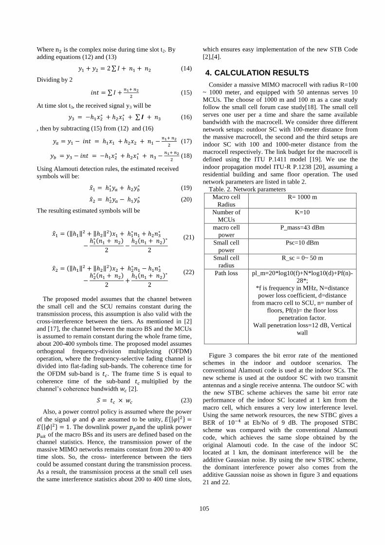
Table. 2. Network parameters
Macro cell
Radius
R= 1000 m
Number of
MCUs
K=10
macro cell
power
P_mass=43 dBm
Small cell
power
Psc=10 dBm
Small cell
radius
R_sc = 0~ 50 m
Path loss pl_m=20*log10(f)+N*log10(d)+Pf(n)-
28*;
*f is frequency in MHz, N=distance
power loss coefficient, d=distance
from macro cell to SCU, n= number of
floors, Pf(n)= the floor loss
penetration factor.
Wall penetration loss=12 dB, Vertical
wall
Figure 3 compares the bit error rate of the mentioned
schemes in the indoor and outdoor scenarios. The
conventional Alamouti code is used at the indoor SCs. The
new scheme is used at the outdoor SC with two transmit
antennas and a single receive antenna. The outdoor SC with
the new STBC scheme achieves the same bit error rate
performance of the indoor SC located at 1 km from the
macro cell, which ensures a very low interference level.
Using the same network resources, the new STBC gives a
BER of at Eb/No of 9 dB. The proposed STBC
scheme was compared with the conventional Alamouti
code, which achieves the same slope obtained by the
original Alamouti code. In the case of the indoor SC
located at 1 km, the dominant interference will be the
additive Gaussian noise. By using the new STBC scheme,
the dominant interference power also comes from the
additive Gaussian noise as shown in figure 3 and equations
21 and 22.

106
Figure 3: Small cell user bit error rate for the new
scheme
Figure 4 compares the throughput of the outdoor SC
using the new STBC and the indoor SCs using
conventional Alamouti code. The slope of throughput of
our outdoor new STBC small cell with 100-meter from the
macro cell equal to the slope of throughput of the indoor
SC with 1000-meter from macro cell. When the SCU is 5
meters away from the SCs, both the proposed outdoor
STBC and the indoor 1 Km SC achieve about 50 Mbps. In
the same conditions, the 100 m SC can only achieve 0.0002
Mbps.
If the macro cells do not use any precoding techniques,
increasing the number of the massive macro cell antennas
increases the number of interference links, which
consequently decreases the throughput of the indoor 100 m
SC, as shown in figure 5. Using the new STBC scheme
with the outdoor SC, the throughput remains constant even
if the number of the macro cell service antennas increases,
and the macro cell does not use any precoding techniques.
Figure 4: Throughput of a small cell user
However the data rate of the small cells will be
decreased by 1/3 of its original value, where the data is sent
using three-time slots via two antennas. So, the data rate
R=2/3, but the aggregate throughput of the small cell will
be significantly enhanced as shown in the calculation
results. The proposed scheme will decrease the
computational complexity of the hardware, making
fabrication of small cells easier. The power consumed by
the small cells and its users will decrease also when using
the new matrix code.
Figure 5: The spectral efficiency of the small cell BS
overlaid with one massive MIMO antennas serves 10 users
5. CONCUSION
We have considered a new space-time block code based
two-tier network architecture which incorporates the
advantageous features of a massive MIMO macro BS
overlaid with small cells. This new scheme used to reduce
the interference to the SC-tier. Our calculation results
indicate that the proposed scheme can significantly
minimize the aggregate cross-tier interference experienced
by SCs without any macro performance loss.
Consequently, we can increase the number of the small
cells BS to offload the macro BS and to increase the
number of users. The calculation results shows great
enhancement in the small cell data rate by decreasing the
cross-interference interference experienced by SCs. Most
importantly, our scheme could be combined with power
control or other interference reduction techniques.
6. REFERENCES
[1].Jeffrey G. Andrews, Stefano Buzzi, Wan Choi, et al.
"What will 5G be". IEEE Journal on selected areas in
communications, vol. 32, no. 6, p. 1065, 2014.
[2]. Emil Bjornson, Luca Sanguinetti, Marios Kountouris.
"Deploying dense networks for maximal energy efficiency:
Small cells meet massive MIMO". IEEE Journal on
Selected Areas in Communications, vol. 34, no. 4, p.
832−847, 2016.
[3].Thomas L. Marzetta. "Massive MIMO: an
introduction". Bell Labs Technical Journal, vol. 20, p.
11−22, 2015.
[4]. Emil Bjornson, Erik G. Larsson, Thomas L. Marzetta.
Massive MIMO: "Ten myths and one critical question".
IEEE Communications Magazine, vol. 54, no. 2, p.
114−123, 2016.

107
[5].E. Björnson, L. Sanguinetti, H. Wymeersch, J. Hoydis,
and T. L. Marzetta, "Massive MIMO is a Reality-What is
Next? Five Promising Research Directions for Antenna
Arrays," arXiv preprint arXiv:1902.07678, 2019
[6].Hien Quoc Ngo, Erik G. Larsson, Thomas L. Marzetta.
"Energy and spectral efficiency of very large multiuser
MIMO systems". IEEE Transactions on Communications,
vol. 61, no. 4, p. 1436−1449, 2013.
[7].M. Z. Aslam, Y. Corre, E. Björnson, and E. G. Larsson,
"Performance of a dense urban massive MIMO network
from a simulated ray-based channel," EURASIP Journal on
Wireless Communications and Networking, vol. 2019, no.
1, p. 106, 2019
[8]. Jubin Jose,Alexei Ashikhmin, Thomas L. Marzetta,
Sriram Vishwanath. "Pilot contamination and precoding in
multi-cell TDD systems". IEEE Transactions on Wireless
Communications, vol. 10, no. 8, p. 2640−2651, 2011.
[9].Kianoush Hosseini, Jakob Hoydis, Stephan ten Brink,
and Merouane Debbah. "Massive MIMO and small cells:
How to densify heterogeneous networks". In
Communications (ICC), IEEE International Conference, p.
5442−5447, 2013.
[10]. Rajoria, Shweta, Aditya Trivedi, and W. Wilfred
Godfrey. "A comprehensive survey: Small cell meets
massive MIMO." Physical communication vol.26, p.40-49,
2018.
[11].Hieu Duy Nguyen, Sumei Sun. " Massive MIMO
versus small-cell systems: Spectral and energy efficiency
comparison". In Communications (ICC), IEEE
International Conference on, p. 1−6, 2016.
[12]. S. Andreev, V. Petrov, M. Dohler, and H.
Yanikomeroglu, "Future of ultra-dense networks beyond
5G: harnessing heterogeneous moving cells," IEEE
Communications Magazine, 2019
[13].Duy Trong Ngo, Tho Le-Ngoc. "Architectures of
small-cell networks and interference management".
Springer, 2014.
[14]. David Muirhead, Muhammad A. Imran, Kamran
Arshad. " A Survey of the Challenges, Opportunities and
Use of Multiple Antennas in Current and Future 5G Small
Cell Base Stations". IEEE Access, vol. 4, p. 2952−2964,
2016.
[15].https://www.ipaccess.com/en/viper/enterprise-small-
cells.
[16].Siavash M. Alamouti. "A simple transmit diversity
technique for wireless communications". IEEE Journal on
selected areas in communications, vol. 16 no. 8, p.
1451−1458, 1998.
[17].Thomas L. Marzetta. "Noncooperative cellular
wireless with unlimited numbers of base station antennas".
IEEE Transactions on Wireless Communications, vol. 9,
no. 11, p. 3590−3600, 2010.
[18].Small cell forum, Interference management in UTMS
UMTS femtocells,
http://scf.io/en/documents/003_Interference_management_i
n_UMTS_femtocells_high-band.php
[19].https://www.itu.int/rec/R-REC-P.1411-9-201706-I/en.
[20].https://www.itu.int/rec/R-REC-P.1238-9-201706-I/en.