small combustion installations -...
TRANSCRIPT

EUR 23214 EN - 2007
Small combustion installations: Techniques, emissions
and measures for emission reduction
Krystyna Kubica, Bostjan Paradiz, Panagiota Dilara

The mission of the Institute for Environment and Sustainability is to provide scientific-technical support to the European Union’s Policies for the protection and sustainable development of the European and global environment. European Commission Joint Research Centre Institute for Environment and Sustainability Contact information Address: Via E. Fermi 2749 - 21027 Ispra (VA) - Italy E-mail: [email protected] Tel.: +39 0332 789207 Fax: +39 0332 785869 http://ies.jrc.ec.europa.eu/ http://www.jrc.ec.europa.eu/ Legal Notice Neither the European Commission nor any person acting on behalf of the Commission is responsible for the use which might be made of this publication.
Europe Direct is a service to help you find answers to your questions about the European Union
Freephone number (*):
00 800 6 7 8 9 10 11
(*) Certain mobile telephone operators do not allow access to 00 800 numbers or these calls may be billed.
A great deal of additional information on the European Union is available on the Internet. It can be accessed through the Europa server http://europa.eu/ JRC 42208 EUR 23214 EN ISBN 978-92-79-08203-0 ISSN 1018-5593 DOI 10.2788/63329 Luxembourg: Office for Official Publications of the European Communities © European Communities, 2007 Reproduction is authorised provided the source is acknowledged Printed in Italy

Content:
1. Introduction .......................................................................................................... 4 2. Emissions.............................................................................................................. 6
2.1 Emission Inventories from Small Combustion Installations ....................... 6 2.2 Profiles of toxic emissions........................................................................... 8 2.3 Combustion technology, type of fuel and emissions................................. 19
3. Fuels and their characteristic .............................................................................. 25 4. Combustion techniques....................................................................................... 28
4.1 Fireplaces................................................................................................... 30 4.1.1 Solid fuel fireplaces ....................................................................... 31 4.1.2 Gas fuels fireplaces........................................................................ 32
4.2 Stoves......................................................................................................... 32 4.2.1 Solid fuel stoves ............................................................................ 32 4.2.2 Liquid/gas stoves ........................................................................... 36
4.3 Small boilers (single household/domestic heating) capacity ≤ 50 kWth.... 36 4.3.1 Solid fuels small boilers ................................................................ 36 4.3.2 Liquid/gas small boilers................................................................. 39
4.4 Boilers with indicative capacity between 50 kWth and 50 MWth .............. 40 4.4.1 Solid fuels boilers .......................................................................... 40 4.4.2 Liquid/gas fuels ............................................................................. 45
4.5 Combined Heat and Power (CHP)............................................................. 47 5. Measures for reduction emissions ...................................................................... 47 6. References .......................................................................................................... 52 7. Biblography ........................................................................................................ 59

1. Introduction Sustainable energy development in the world, EU-25 and each country by itself is determined by the continued availability of energy in sufficient quality and quantity, the growing accessibility of energy and its compatibility with public concerns, be they developmental, environmental or social (Energy; www.worldenergy.org). The global, regional and local trend of energy sources demand has been one of increase over many of the past years. According to their specific properties, the various energy sources have different focuses of application. Natural gas is mainly used for heating purposes. In the traffic sector, it is mineral – oil products that dominate. Nuclear energy and coal are used exclusively or predominately in power plants. Hard coal is used for two main purposes – electricity generation (steam coal) and coke production. Coal provides over 23% of global primary energy needs, and generates about 38% of the world’s electricity (www.worldenergy.org). Renewable energy sources (solid biofuels, solar energy, wind energy, water power, geothermal energy etc.) are applied in both the heating market and power generation. In EU-25 half of electricity is produced from fossil fuels, 32% of total power is generated from coal (i.e. hard coal and lignite) although in some countries, such as Poland, this contribution is much higher, (in Poland above 80%).
Many countries, in particular those which the economies in transition (Central and Eastern European Countries – CEEC) use coal as a main fuel for domestic and commercial heating. Currently it is observed that the use of biomass for production of heat and energy in small combustion installations up to 50MWt has been growing. Use of renewable energy (RE) has also been growing to reach 12% RE in 2010 as proposed by the EU White Paper, or 25% RE in 2020 as proposed by a number of NGOs. Global energy scenarios to 2050 and beyond (www.worldenergy.org ) that were elaborated by the World Energy Council include six variants of energy scenarios. Scenario A3 is one of them that can achieve atmospheric concentrations of carbon dioxide less than double of the pre-industrial levels by the year 2100. In this scenario emphasis is being placed on the fast growth of renewable energy sources. So in the future, emissions from SCIs should decrease due to the renewable energy sources being implemented first and foremost in those sectors.
Figure 1.1. Global energy scenarios A3 (EDC; www.worldenergy.org)
Application of fossil fuel for production of energy has direct influence to environmental quality. Its use in energy production is a major source of NOx, SO2, CO2, TSP, PM10, PM2.5, HM emissions. The link between air pollution and human health has been established for over a

century. This has led to major changes in the way fossil fuels are used particularly over the past fifty years in both stationary and mobile sources. Pollution legislation such as emission standards is the only way of ensuring that air pollution is brought under control and that the detrimental effects on human health are minimized. Environmental quality was the original driver for environmental legislation. Deterioration of air quality prompted authorities to find a way to reduce ambient concentrations of pollutants, mainly by controlling large emission sources and mostly ignoring small combustion sources.
Currently the main types of emission legislation seen throughout the world are: emissions limits – usually linked to penalties for non-compliance, emission trading using the “cap and trade” approach, Best Available Technology - BAT in Europe (Maximum Achievable Control Technology - MACT in USA) and Integrated Pollution Prevention and Control. The United Nations has several protocols and programmes that cover emissions from energy production sources. The main are: the United Nations Economic Commisions For Europe (UNECE) Convention on Long-Range Transboundary Air Pollution (LRTAP) which was signed in 1979 by 33 countries, including the USA and Canada and most EU countries, and the Kyoto Protocol (concerned mostly with greenhouse gases, both direct as well as indirect).
Most EU legislation is given in the form of directives as this allows the Member states more flexibility in achieving environmental objectives. The main directives connected with energy generations that are: the Integrated Pollution Prevention and Control (IPPC) Directive of 1996 (96/61/EC), National Emissions Ceilings Directive (NECD)(2001/81/EC) for acidifying and ozone-forming air pollutants (SO2, NOx, VOC’s and ammonia) and the Large Combustion Plant Directive (LCPD)(2001/80/EC), which originally established emission standards for new plants larger than 50 MWth, irrespective of the fuel used. The Renewable Energy Directive 2001/77/EC is likely to promote the use of renewable energy for electricity production. All these environmental legislation contributed to decreasing air pollution coming from large combustion sources, but the air quality has still not achieved good quality.
The inventory emission data, which are drawn from various sources, including submissions to UNFCCC (United Nations Framework Convention on Climate Change), UNECE/CLRTAP (TFEIP-Task Force on Emission Inventories and Projections; UNECE-United Nations Economic Commission for Europe) and data from the RAINS model (Regional Air Pollution Information and Simulation Model) for use in the CAFE programme and national inventories have been showing that air pollution deriving from non-industrial energy production still has a great contribution in total national emission of pollutants. Contributions of small combustion installations emission to total emission vary and depend on pollutants type and given country. Non-industrial energy production is applied in small-scale combustion installations (SCIs) with a thermal capacity ≤ 50 MWth, also known as small combustion plants (SCPs). Small combustion plants are used in the following activity sources:
• District heating • Commercial and institutional • Residential • Agriculture / Forestry / Fishing, and • Other (including military).
Combustion of solid fuels is a source of pollutant emission to the atmosphere. Low combustion efficiency (usually not exceeding 50% average per year, in particular for installation capacity below 1MWth), poor fuel quality and no or little cleaning of exhaust gasses result in higher emissions. Especially the combustion of coal either in residential heating appliances (i.e. stoves, furnaces) or boilers of low power is widely considered to be of the most pollutant emitting sources.

Research carried out in the past few years proves that besides significant emission of CO, SO2, NOx and particles, these sources are also responsible for significant amount of organic pollutants (TOC), including polycyclic aromatic hydrocarbons (PAH), dioxins and furans – PCDD/F, and VOC such as aliphatic hydrocarbons, benzene and its derivatives (BTX), aldehydes and ketones, but also phenol and its alkyl derivatives, heterocompounds of nitrogen and sulphur etc., and heavy metals (Kubica, 1997/1; Kubica, 2003/1 and Williams, et al., 2001). The negative impact from the use of low efficiency heating devices is multiplied by the combustion of fuels of poor quality with significant sulphur and ash contents, low calorific value and coal sludge. This is especially true for the Central and Eastern European Countries (CEEC) where the cold climate, ease of access to coal and poor economic conditions make the heating of residences by coal an attractive option. At the same time biomass becomes a more and more popular fuel used in residential sector, due to the strategy to achieve reduction of CO2 in same countries. But also installations burning biomass are often characterized by higher emissions of particulates and related pollutants.
2. Emissions
2.1 Emission Inventories from Small Combustion Installations
The contribution of emissions from small combustion installations to the total emissions varies and depends on pollutants type and given country. A very important role is played by the emissions from small residential installations which are typically responsible for more than a third of the total particulate matter emissions of stationary combustion (UBA, 1998a; APEG, 1999; Olendrzynski, 2002; )) but in some countries this sector may even dominate. For example in Austria in 1995 more than 70% of PM emissions from stationary combustion are thought to have originated from this source (Winiwarter et al., 2001).
The contribution of fuel combustion in commercial, residential and other small capacity installations to the total heavy metals emission in Europe in 1990 was for As 12.4%, for Cd 15.9% and for Hg 27.8% (Berdowski, 1997).
Also emissions of PAH and PCDD/F from those activities are significant. For instance, residential use of solid fuels and biomass accounts for about half of the emissions of polycyclic aromatic hydrocarbons (COM(2003)) and one third of dioxin emissions in the EU (Quass, 2000). Those are characterized by seasonal variations, as it was reported that emission of B[a]P in winter is 10% higher than in summer (Baart, 1995).
Many countries using coal (but also biomass) as a major part of domestic and commercial heating requirements have serious air pollution problems, such as example Austria and Poland. In Austria, the residential combustion is already the most significant source of dioxins (Quass, 2000). In Poland the TSP emissions from small combustion sources is 35% of the national total emissions, and up to 90% of the total TSP emissions from combustion activities (Olendrzynski, 2002). It was further reported that in Poland the main source of PCDD/F (47% of national total) and PAH emission (87% of national total) are non-industrial combustion plants (residential, district heating, agriculture, forestry). The share of heavy metals emissions such as Cd, As, Cr, Cu, Ni, Zn due to high emissions of TSP is also higher (respectively: 55%, 36%, 27%, 25%, 50%, 30%). In general those sources have a more important contribution to the above-mentioned pollutants where a higher share of solid fuels exists in the fuel mix of the residential sector.
Furthermore, due to the particularly low height of the stacks used in such installations (usually not exceeding 10 m), the emissions from such residential heating appliances, especially in highly urbanised areas, result in high concentration of pollutants at ground level and thus more

dangerous for the human health, both by direct inhalation, as well as by ingestion with contaminated food. This particularity makes this sector responsible for the “low-height emissions” in urban centres where such appliances are used. The effect of environment pollution caused by coal combustion for residential heating is particularly obvious in large urban centres where about 60% of annual pollutants emission derives from municipal sources, while it can reach 90% during the winter time. This relates especially to such harmful pollutants as CO, particulate matter (TSP, PM) as well as the above-mentioned organic pollutants, including PCDD/F and PAH. In Belarus small combustion sources provide abut 40% of total PCDD/F emissions, and about 80% of indicator PAH emission (Kakareka et al., 2003). In general those sources have a more important contribution to the above-mentioned pollutants where a higher share of solid fuels exists in the fuel mix of the residential sector.
The estimated contribution of emissions released from small combustion installations to the total European emissions is presented in Table 2.1. These sources represent one of the strongest sources of particulate matter and even in the future they might remain an important contributor and their share might even increase for some pollutants and for some scenarios. It is also worthwhile to note that there are significant regional differences, e.g., in the EU-15, the share of this sector in particulate emissions has been typically below 20 % and is expected to decline further to about 12 and 17 % for PM10 and PM2.5, respectively; in the EU-New Members this share was in the 90’s above 30 % and is expected to decline to about 22 and 28 % for PM10 and PM2.5, respectively. Projections presented for 2010 are for illustrative purpose only and refer to the European energy scenarios developed by the PRIMES model (CEC, 2003 and CEPMEIP, 2002) and implemented in the RAINS model recently.
The emission contribution of residential sources in the future will depend strongly from the assumptions about fuel switching (coal to gas) that has been happening in the last decade, a trend that is expected to continue and eventually lead to lower emissions of particulate matter but possibly at a cost of increased emissions of other pollutants as for example NOx. At the same time biomass becomes a more and more popular fuel used in the residential sector; its use is strongly encouraged in some countries and is seen as a part of the strategy to achieve reductions of CO2, however installations burning biomass are often characterized by higher emissions of particulates (Williams et al., 2001; Kubica et al., 1997/2 and 2001/1; Houck et al., 1998/1). All this indicates that air emissions from this source will remain an important part of total emissions and more attention should be focused on them.
Tab.2.1. Contribution to total emissions (RAINS model results) Year Pollutant
1990 1995 2010
Oxides of nitrogen 4.5% 5% 7%
Sulphur dioxide 11% 8% 7%
Ammonia About 0.5% - 1%
NMVOC(1) 7% 7% 7%
PM2.5(2) 25% 25% 19%
PM10(2) 22% 20% 15%
(Source: IIASA, 2004) (1) Contributions vary widely from country to country, e.g. 1% - 3% in the Netherlands or Italy, 10%-15% in
Austria and 25%-30% in Sweden, (2) Contributions vary widely from country to country, e.g. 2%-4% in the Netherlands and 40%-50% in Austria and
Sweden,).

Furthermore the influence of those sources on the local air quality could be significant due to the low height of the flue gas releases, even where their share in total emissions is not dominant. This is particularly the case in the regions where solid fuels are predominately used in the residential sector. For instance, the occasional exceeding of the SO2 ambient air target value could still be expected in the UK in some areas after the year 2000 (The Air Quality Strategy for UK; 2000) because of this reason.
2.2 Profiles of toxic emissions
In general, the nature of the pollutants formed during all kinds of combustion processes is the same, although the contents of each of them may differ depending on the type of fuel, the combustion temperature, the combustor conditions, and the time-history profiles of the reactants and products. For both, gaseous and liquid fuels, the emissions of pollutants are not significantly higher in comparison to industrial scale boilers due to the quality of fuels and design of burners and boilers, except for gaseous and liquid fuelled fireplaces and stoves because of their simple organization of combustion process. For the above-mentioned installations the same pollutants are generated as for solid fuels but their quantities are in general significantly lower.
The technologies of solid fuels (raw coals, solid coal derived fuels, solid biofuels, refused derived fuels, and so on) combustion by means of fixed bed are carried on under conditions far from optimum (by means of stoves, furnaces and old design boilers) which results in incomplete combustion and in consequence they are the source of not only classic gaseous combustion pollutants (NOx, SO2, CO, CO2, TSP, PM10, PM2.5, HM) but also of the most hazardous pollutants – organic compounds such as the persistent organic pollutants (POP – PCDD/F and PAH) and other toxic atmospheric organic pollutants (TOAC as sum of VOC, SVOC; POP); volatile organic compounds – VOC, and semi-volatile organic compounds SVOC and non volatile organic compounds (NVOC – are comprised of more than 4-rings PAH). The VOC responsible for generation of troposphere ozone (POCP), are aliphatic hydrocarbons C1-C10, BTX, other aliphatic derivatives of benzene and ox-compounds (Kubica, 1997/1 and 2003/1; Williams et al., 2001). Emission of ammonia (NH3) is not very relevant for the combustion of fuels in medium size boilers but it is observed among the products of incomplete combustion process, which is carried on in fireplaces, stoves and old chamber boilers (Bartle, at al., 1996). Volatile organic compounds (VOC) that are any organic compound except methane having at 293.15 K a vapor pressure of 0.01 kP or more, or having a corresponding volatility under the particular conditions of use. Table 2.2. is presenting the list of 56 main VOC compounds that are numbered among to ozone precursors in accordance with the US EPA (Jaecker- Voirol J, 2000).
Table 2.2. Main compounds of VOCs group to be amounted to ozone precursors in accordance with the US EPA (Jaecker- Voirol J, 2000)
Ethane 2-Methylopentane Ethylbenzene Ethylene 3-Methylopentane m- and p- Ksylene Propane Izoprene Styrene Propylene 2-Methyl-1-pentene o-Xylene Izobutane Hexane n-Nonane n-Butane Methylcyklopentane Isopropyl benzene Acethylene 2,4-Dimethylpentane n-Propyl benzene trans-2-Butene Benzene m-Ethyl toluene

1-Butene Cykloheksane p-Ethyl toluene Cis-2-Butene 2-Methylheksane 1,3,5-Trimethylobenzene Cyklopentane 2,3-Dimethylpentane o-Ethyltoluene Izopentane 3-Methylheksane 1,2,4-Trimethylbenzene n-Pentane 2,2,4-Trimethylpentane n-Decane
trans-2-Pentene n-Heptane, Methyl cyklohexane, 2,3,4 – Trimethylpentane 1,2,3-Trimethylbenzene
1-Pentene Toluene m-Diethylbenzene Cis-2-Pentene 2-Methylheptane p-Diethylbenzene 2,2-Dimethylbutane 3-Methylheptane n-Undecane 2,3-Dimethylbutane n-Octane n-Dodecane
The group of SVOC includes aromatic hydrocarbons, together with 16 PAH by EPA, among which are listed benzo(a)pyrene and hydrocarbons of 3-, 4-, 5- rings with carcinogenic and mutagenic properties, Table 2.3. There are important benzene derivatives of anthracene, for instance dibenzo(a,h)anthracene, which toxicity factor is higher than for benzo(a)pyrene.
Tablica 2.3. Carcinogenic factors of 16 PAHs according to EPA list related to benzo(a)pyrene
Carcinogenic factors according to List Name Structural
formula Molecular formula (Nisbet,
1992) (Clement, 1998)
(US EPA, 1993)
1 Naphthalene C10H8 0,001 n.d n.d
2 Acenaphthylene C10H6(CH2)2 0,001 n.d n.d
3 Acenaphthene C10H6(CH2)2 0,001 n.d n.d
4 Fluorene C13H10 0,001 n.d n.d
5 Anthracene C14H10 0,01 0,32 n.d
6 Phenanthrene C14H10 0,001 n.d n.d
7 Fluoranthene C16H10 0,001 n.d n.d
8 Pyrene C16H10 0,001 0,08 n.d
9 Benzo(a)anthracene C18H12 0,1 0,15 0,1
10 Chrysene C18H12 0,01 0 0
11 Benzo(b)fluoranthene C20H12
0,1 0,14 0,1
12 Benzo(k)fluoranthene C20H12 0,1 0,07 0,01
13 Benzo(a)pirene C20H12 1 1 1
14 Dibenzo(a,h)anthracene C22H14
5 1,1 1

15 Benzo(g,h,i)perylene C22H14
0,01 0,02 n.d
16 Indeno(1,2,3-c,d)pirene C22H12 0,1 0,23 0,1
* n.d – non determined
Such compounds are present in the combustion gases both in the gaseous phase, as well as on particles. Compounds from VOC, SVOC and HVOC groups are present in combustion gases in the form of aerosols, especially in the gaseous phase, absorbent and phase associated with dust particles (PM2,5 and PM10 ). The share of PM10 in total TSP from combustion of coal in the stoves was determined to be about 70% (Kubica, 2003; Hlawiczka et al., 2003). They are especially dangerous in this last form because inhaled particles can cause big effects to the human health. These emissions from SCIs are more dangerous due to the PMs contain also a lot of heavy metals - Cd, Tl, Hg, Sb, As, Pb, Cr, Co, Cu, Mn, Ni, V. Furthermore being emitted through low high chimneys they can directly reach the receptor and thus influence human health. Most dangerous to human are those heavy metals that are emitted not only as included in TSP but in vapor phase also. For instance, mercury is of the most health risk due to it being emitted to the atmosphere in a significant part as a gaseous form. Mercury emissions from stove and similar combustion appliances are on average about 50% in vapour phase, while the remaining part is present in the particulate matter trapped in the chimney duct and/or emitted to the air (Hlawiczka et al, 2003).
In general, the nature of the pollutants formed during all kinds of combustion processes is the same, although the contents of each of them may differ depending on the type of fuel, the combustion temperature, the combustor conditions, and the time-history profiles of the reactants and products. It’s necessary to notice that that relation is treating in particular solid fuel burned in SCIs as well as these pollutants, which are products of incomplete combustion process of fuels. From the speciation of selected NMVOCs for both coal and solid biofuels (wood pellets) combusted in conventional stoves it is clear that each fuel has a characteristic fingerprint (see Figures 2.1 above and 2.2 below) (Kubica K., (2003/5). Wood biofuels for instance, emit higher levels of benzene, toluene and xylene (BTX) to the atmosphere when compared to coal combustion. The difference is also evident on the amount and profiles of PAHs emitted by those fuels as seen in the Figure 2.4 below.

Fig.2.1 Profiles of selected NMVOCs from combustion of coal and wood pellet in conventional stove (Kubica, 2003/6)
0
5
10
15
20
25
30
35
40
45
50
n-Pen
tane/10
Dimeth
ylpen
tane/1
0
Methyle
thylke
tone
X-cyclo
heks
ane
Heptan
e
Tetram
ethylh
eptan
e
n-Octa
ne
n-Non
ane
Propylb
enze
ne
n-Dec
ane
[mg/
m3]
Coal
Wood Pellets

0
2000
4000
6000
8000
10000
12000
Naphta
lene
Acena
phthy
lene
Acena
phthe
ne
Fluoren
e
Fenan
trene
Anthrac
ene
Fluoran
tene
Pyrene
Benzo
(a)an
thrac
ene
Chryse
ne
Benzo
(b+k)f
luoran
thene
Benzo
(a)py
rene
Db(a,h)
anthr
.+Ind
(1,2,3
)pyr
Benzo
(g,h,i
)peryl
ene
[ug/
MJ]
Coal [μg /MJ]
Wood Pellet [μg /MJ]
Fig. 2.2 Profiles of 16 PAHs from combustion of coal and wood pellet in conventional stove (Kubica, 2003/5)
The profiles of VOCs and PAHs depend on the kind of combustion techniques used (Figure 2.3, 2.4 and 2.5). Implementing clean solid fuel combustion reduces the emission and fuel consumption, but still the emitted quantities are depending strongly on the kind of fuel (Kubica, 2003/1).
0
200
400
600
800
1000
1200
1400
Pent
an
Ace
ton
2-m
etylop
enta
n
Hek
san
Met
yloe
tyloke
ton
Ben
zen
Hep
tan
Toluen
Oktan
m- +
p-k
sylen
Non
an
o-ks
ylen
Pro
pylobe
nzen
1,3,
5-
trim
etyo
benz
en
Dek
an
1,2,
4-
trim
etylob
enze
n
VOCs
[mg/
m3 ]
[A] [B]
Figure 2.3 Profile of [mg/m3] from coal combustion in fixed bed: stove – A; retort hearth boiler – B (value multiplied *100) (Kubica, 2000 and 2003/1)

Figure 2.4 Profile of [mg/m3] from coal combustion in fixed bed: stove – A; retort hearth boiler – B (value multiplied *100) (Kubica, 2000 and 2003/1)
Fig. 2.5 PAH’s profile: [A] – dichlormethylene extract from coal; [B] – benzene extract from coal; [C] – liquid products of coal pyrolysis in 520oC; [D] – liquid products of coal pyrolysis in 850oC; [E] – flue gases from coal combustion in fixed bed - stove; [F] – flue gases from coal combustion in retort hearth boiler (Kubica, 2000) Emitted organic pollutants from combustion in SCIs also contain dioxins and furans (Moche, 1998; Williams et al. 2001). It was found that a significantly influence on the quantities of dioxins and furans emitted play the combustion process organization, chemical composition of fuel and homogenisation of fuel properties and finally its chlorine contents. Little research has been devoted up to now on the measurement or estimation of dioxin emissions from solid fuel combustion in small residential heating. However, there are strong indications that there is a
0
0,5
1
1,5
2
2,5
3
3,5
CH4 C2H2 C2H4 C2H6 C3H6 C3H8 C4H10 H2
[mg/
m3 ]
[A] [B]

high potentiality for production of dioxins under certain circumstances. Table 2.3 is contained the weighting factors used to calculate I – TEF (I-TEQ).
Table 2.3. Weighting factors to calculate I – TEF (I-TEQ)
Dioxins I – TEF (I-TEQ) 2,3,7,8 – tetrachloro dibenzodioxin (2378TCDD) 1 1,2,3,7,8 – pentachloro dibenzodioxin (12378PeCDD) 0,5 1,2,3,4,7,8 – hexachloro dibenzodioxin (123478HxCDD) 0,1 1,2,3,6,7,8 – hexachloro dibenzodioxin (123678HxCDD) 0,1 1,2,3,7,8,9 – hexachloro dibenzodioxin (123789HxCDD) 0,1 1,2,3,4,6,7,8 – heptachloro dibenzodioxin (1234678HpCDD) 0,01 Octachloro dibenzodioxin (OCDD) 0,001 Frans 2,3,7,8 – tetrachloro dibenzofuran (2378TCDF) 0,1 1,2,3,7,8 – pentachloro dibenzofuran (12378PeCDF) 0,05 2,3,4,7,8 – pentachloro dibenzofuran (23478PeCDF) 0,5 1,2,3,4,7,8 – hexachloro dibenzofuran (123478HxCDF) 0,1 1,2,3,6,7,8 – hexachloro dibenzofuran (123678HxCDF) 0,1 2,3,4,6,7,8 – hexachloro dibenzofuran (234678HxCDF) 0,1 1,2,3,7,8,9 – hexachloro dibenzofuran (123789HxCDF) 0,1 1,2,3,4,6,7,8 – heptachloro dibenzofuran (1234678HpCDF) 0,01 1,2,3,4,7,8,9 – heptachloro dibenzofuran (1234789HpCDF) 0,01 Octachloro dibenzofuran (OCDF) 0,001
The high emission of PCDDs/Fs from coal combustion, especially polish coal, is discussed in both Austrian and German studies (Quass, 2000; Moche, 1998). The research reveals also much higher dioxins emission from combustion of coal imported from Poland, which ranges from 108,5 up to 663,9 µg I-TEQ/tone of combusted fuel (Moche, 1998). These amounts are comparable to emissions observed during the tests carried out in Krakow, including co-combustion of coal and wastes (Grochowalski, 2002).
Relatively high dioxins emission from the samples of Polish coal as seen in the Austrian and German works can be derived from relatively high chlorine contents in Polish coals, that usually ranges from trace quantities up to 0,4%, or even up to 1,5% (Kubica 2003/1).
Between 1999 and 2002, within the scope of research projects budgets funded by EC (INCO-COPERNICUS programme) combustion tests were performed using several types of solid fuels: two coals with different chlorine contents, different types of wooden biomass and mixtures of coal and biomass, either in briquette form and a two-component mixture were carried out (Williams at al.,2001, Danihelka et al., 2001). These fuels were combusted by means of a chamber water-boiler of 30kW capacity, with combustion at the bottom part of the bed (co-current combustion with distribution of air supplied for the process).
For the comparison purposes emissions were also measured from the combustion of the same type of coals in a retort boiler (Kubica, 2003/5). Retort boiler of stoker type with continuous, automatic fuel supply and controlled amount of air supplied to combustion chamber, with applied technique of combustion in the upper part of the bed, co-current combustion, can be listed among the most modern and the most effective low capacity boilers designs, enabling “clean combustion of coal”.
The test results are presented on Figure 5. As can be seen from the figure, the PCDD/Fs emission factors, expressed as ng I-TEQ/m3, are in every case (except of retort boiler)

significantly higher than allowable value specified by the 2000/76/EC Directive for waste incineration plants (Directive, 2000) 2000/76/EC of the European Parliament and of the Council of 4 December 2000 on the incineration of the waste), which is equal to 0,1 ng I-TEQ/m3.
Fig. 5: PCDD/Fs Toxic Equivalent values for different types of fuel – technique combinations. R means Retort Heart Boiler, B - coal of bean size, N – coal of nut size. The red line indicates the limit for waste incineration (Kubica, 2003/6)
The amount of PCDDs/Fs emitted from chamber boilers irregardless of the combusted fuel type was generally at the same level of decimal units of µg I-TEQ/tone. Combusted biomass, either wood or agricultural, emits significant quantities of dioxins (from 2 up to 33 µg I-TEQ/tone for wood biomass, from 12 up to 13 µg I-TEQ/tone of straw). However, it should be noted that the used boiler was not adopted for biomass combustion (Williams, 2000). In the case of hard coal, a fuel of lower (2,5 times) chlorine contents (Julian coal) emitted more than 3-times less PCDDs/Fs.
A decrease of grain size also lowered dioxins emission to about 30% (Danihelka, 2001). In the case of briquetted fuels dioxins emission has been generally lower as it was also observed by German studies (Moche, 1998). While the above-mentioned effect has not been observed for the mixtures of coal and straw; in this case an addition of approximately 10% (m/m) of straw or sawdust did not cause significant differences by dioxins emission. The current research indicates that the influence of chlorine contents is observed on individual fuel groups but a significantly higher impact have combustion process organization, chemical composition of fuel and homogenisation of fuel properties and finally chlorine contents.
Total I-TEQ PCDD/F
0.0
0.5
1.0
1.5
2.0
2.5
3.0
3.5
4.0
CoaI "J
ulian
"BR
CoaI "J
ulian
"N
Coal "W
ujek"N
Coal "W
UJEK"B
Rape S
traw
Whe
at Stra
w
Lump P
ine W
ood
Brique
ttes o
f Pine
Woo
d Saw
dust
Brique
ttes o
f Slud
ge an
d Coa
l "Juli
an"
Brique
ttes o
f Saw
dust
and C
oal "W
ujek"
Mixture
of S
awdu
st an
d Coa
l "WUJE
K"
Mixture
of R
ape S
traw an
d Coa
l "WUJE
K"
Various Types of Solid Fuels
ng I-
TEQ
/Nm
3 (r
ecal
cula
ted
to 1
0% O
2)

Because emission inventory according to UNEECE EMEP inventory guidelines concern selected pollutants from combustion processes in SCIs, they are further discussed in more detail. Relevant pollutants are sulphur dioxide (SO2), nitrogen oxides (NOx), total suspended particulate matter (TSP), suspended particulate matter <10 µm (PM10), suspended particulate matter <2.5 µm (PM2.5), heavy metals: arsenic (As), cadmium (Cd), chromium (Cr), copper (Cu), mercury (Hg), nickel (Ni), lead (Pb), selenium (Se), zinc (Zn), polycyclic aromatic hydrocarbons (PAH) which are: benzo(a)pyrene (BaP), benzo(b)fluorantene (BbF), benzo(k)fluoranthene (BkF), indeno(1,2,3-cd)pyrene (I_P), and their sum as total 1-4 as well as dioxins and furans (PCDD/F), carbon monoxide (CO), non-methane organic volatile compounds (NMVOC). Emission of ammonia (NH3) is of less importance.
The emissions are released through the stack and trough the “chimney” as it is commonly named in residential sector. Fugitive emissions (from seals etc.) can be neglected for small combustion installations.
NH3 – Small amounts of ammonia may be emitted as a result of incomplete combustion process of all solid fuels containing nitrogen, via its incomplete conversion, and formation during the pyrolysis step of the combustion process. This occurs in cases in which the combustion temperatures are very low (fireplaces, stoves, old design boilers). NH3 emissions generally can be reduced by primary measures aiming to reduce products of incomplete combustion and increase energy efficiency.
SO2 – The emission of sulphur dioxide are related to the sulphur content in the fuel) , which for the coal normally varies between 0,1 and 1,5% (dmf) (up to an extreme value of 10%) and for oil fuel (including heavy oil fuels) from 0,3% up to 3,0 % ( As far as S limit in Slovenia for light fuel oils is 0.2% for a quite of some time, and in Austria it is even lower. DIN 51603,1992; Williams et al. 2000; Kubica 2003). The sulphur content in gas is usually negligible. Sulphur appears in coal in three forms: inorganic – mainly pyritic sulphur (FeS2), and sulphur salts; organic – as sulphides, disulfides; and cyclic compounds mainly tiofene compounds; elemental sulphur. However in biomass sulphur appears mainly as organic and salts sulphur. Pyritic and organic sulphur is a major part of the sulphur in coal; both types are responsible for SOx formation (SO2-usual >95%, and SO3 - <5% is formed at lower temperatures). The emission of SO2 directly depends on sulphur contents in fuels (particular organics and pyritic forms in coal fuel). About 70% of sulphur from raw solid fuels is released as SO2 with typical concentrations in the stack gases 200-2000 ppm (Williams et al. 2000). It should be mentioned that the emission of SO2 is directly dependent on sulphur content of fuel, but for coals also the content of the calcium carbonate is relevant due to its chemisorbtion of generated SO2.
NOx - Nitric oxides as the sum of NO (>90% of N-fuels converted), NO2 (<10% of N-fuels converted), are recalculated to NO2 - they have to be for the purpose of the convention-. Nitrogen emissions are the result of partial oxidation of fuel nitrogen (“fuel NO”). The main amount of nitric oxides is emitted as NO. The emissions of NOx increase with increasing nitrogen contents in the fuel, excess air ratio, and higher combustion temperature. Nitrogen contents in the fuels varies: coals contain nitrogen mainly as N-organic from 0,5% to 2,9% (daf), (average about 1,4%), biomass contains N as N-organic forms from 0,05% to 0,8% (daf); for coke the N-contents is between 0,6 to 1,55% (daf), for peat between 0,7 and 4,4 % (daf). The content of nitrogen (mainly organic N) in liquid fuels varies for heavy oils between 0,1 and 0,8%, and for fuel oils between 0,005 and 0,07% (Kolar J. 1990). Natural gas contains no organically bounded nitrogen. Additional NOx may be formed from nitrogen in the air under certain conditions, as “thermal NO” (“NOthermal), and as “prompt-NO” is generated by the flames surrounding individual particles, through free radicals reactions. Due to non-relevant

content of nitrogen in natural gas thermal-NO is generated during its combustion only. Nitrogen in the air starts to react with O-radicals and forms NO at temperatures above approximately 1300oC, its amount depending on O2 concentration and residence time. Because of the fact that temperatures of combustion in small combustion installations are, in general, lower then 1300oC the thermal NOx formation is not important, but there is a post-flame NOx – problem. The major formation of thermal NOx occurs in the post-flame gases (after the main combustion process). Due to the developing of small boilers design, the share of those may be increasing. NOx emissions may be reduced by both primary and secondary measures aiming at emission reduction, but secondary measures are not still applied in small installations due to economic reasons.
TSP, PM10, PM2.5 – Particles, Particulate Matter in flue gases from combustion of fuels (in particular of solid fuels and biomass) might be defined as carbon, smoke, soot, stack solid or fly ash. Particulate matter occur at three groups in fuel combustion products. The first group may contain smoke that is formed via gaseous phase combustion or pyrolysis process as a result of incomplete combustion of fuels: soot as product of aliphatic, aromatic radical’s reactions in the flame reaction zone in the presence of hydrogen and oxygenated species: as CO and some mineral compounds as catalytic species, and VOC, tar/heavy aromatic compounds species as results of incomplete combustion of coal/biomass devolatilization/pyrolysis products (from first combustion step process), and secondary sulphuric and nitric compounds. Condensed heavy hydrocarbons (tar substances) are an important, and in some cases, the main contributor to the total particle emission level in small-scale solid fuels combustion applications such as fireplaces, stoves and old design boilers.
Next groups (second and third) may contain ash particles or cenospheres that are largely produced from fuels mineral matter, containing oxides and salts (S, Cl) of Ca, Mg, Si, Fe, K, Na, P, and heavy metals, and unburned carbon; this is called carbon-in-ash (or loss on ignition). Particulate emissions in small combustion installations may be reduced in two ways: first of all, by the optimal design of combustion chamber (such as decrease of incomplete combustion process of fuels by improvement of technological conditions, control of distribution air/fuel ratio, increase of fuel and air mixing degree, and their mixing turbulence - intensity), and secondly by increased fuels quality. The last method is applied first and foremost for small combustion installations that use fixed bed combustion technologies - stoves, fireplaces, boilers, especially of capacity <1MWt. Due to technical and economical issues secondary reduction measures are not applied for these activities. Secondary measures of particle emissions reduction are utilized to reduce the particle emissions in small combustion installations of capacity above 1MWt. TSP from combustion of solid fuels in particular in SCIs contain all above-mentioned particulate matter (Berdowski 1997/2, Kubica, 1997/1 and 2003/1, McElroy; 1982; Tullin, 2000).
Heavy metals (HM) – Most of heavy metals considered (As, Cd, Cr, Cu, Hg, Ni, Pb, Se, and Zn) are usually released as compounds associated with and/or adsorbed on particles (e.g. sulfides, chlorides or organic compounds). Hg and Se are at least partly present only in the vapor phase (Hlawiczka et al, 2003). Less volatile elements tend to condensate onto the surface of smaller particles in the exhaust gases. Therefore the emission of heavy metals strongly depends on their contents in fuels. Coal and its derivatives normally contain a several orders of magnitude higher than in oil (exceptionally for Ni and V in heavy oils) and in natural gas (about 2-5 μg/m3; van der Most, P.F.J. et al. 1992). All virgin biomass also contains heavy metals. Their content depends on the type of biomass. Higher emission of Cd, and Zn were observed in comparison to those from coal (Williams et al, 2001). During the combustion of coal and biomass, particles undergo complex changes, which lead to the vaporization of volatile elements. The rate of volatilization of heavy metal compounds depends on technology characteristics (type of boilers; combustion temperature) and on fuel characteristics (their contents of metals, fraction of

inorganic species, such as calcium). Contamination of biomass fuels, such as impregnated or painted wood may cause significantly higher amounts of heavy metals emitted (e.g. Cr, As). Heavy metals emissions can be reduced by secondary emission reduction measures.
PCDD/F – The emissions of dioxins and furans are highly dependent on the conditions under which combustion and exhaust gases cooling is carried on. Carbon, chlorine, catalyst (mineral matter of fuel) and oxygen excess are necessary for the formation of PCDD/F. They are found to be consequence of the novo synthesis in the temperature interval between 180oC and 500oC (Karasek et al., 1987). It was reported that combustion of coal and biomass in small boilers, and stoves that employ incomplete combustion techniques, results in emission of significant amounts of PCDD/F (about 0,3-0,823 µg/GJ, and 0,1-1,6 µg/GJ respectively). Co-combustion of coal and wastes is usually practiced in residential stoves and gives several times higher emission factors (average between 5 and 10), (Grochowalski A., 2002). Introduction of advanced combustion techniques such as upper-fire in stoker boilers results in the significant reduction of emission of PCDD/Fs, (Kubica, 2003/2).
PAH – Policyclic aromatic hydrocarbons it is family of thousand compounds. EPA proposed the list of 16 PAHs but EMEP inventory include a sum of BaP, BbF, BkF, and I_P. Whereas in ambient atmosphere at least 8 PAHs (benzo(a)pyrene, benzo(a)anthracene, benzo(b)fluoranthene, benzo(j)fluoranthene, benzo(k)fluoranthene, indeno(1,2,3-cd)pyrene, dibenz(a,h)anthracene and fluoranthene) are proposed to be determine according to the Directive (COM(2003). Benzo(a)pyrene is regularly used as a marker for the carcinogenic risk of polycyclic aromatic hydrocarbons in ambient air. Emissions of all polycyclic aromatic hydrocarbons results from incomplete (intermediate) conversion of fuel carbon to CO2 and fuel hydrogen to H2O, (Kubica, 1997/1; and 2003/1). PAHs are usually distinguished separately from other hydrocarbons due to their carcinogenic impact. As is the case also for CO, and NMVOC, emissions of PAH are depended on combustion temperatures (too low temperatures is increasing their production), the residence time and availability of oxygen as well as the homogenization of fuel and air in reaction zone. It was reported that coal stoves and old type boilers (hand fuelled) emit several times higher amounts of PAH in comparison to new design boilers (capacity below 50kW) like boilers of semi-automatic feeding (Kubica K., 1997/1, 2002, 2003).
CO – Carbon monoxide is found in combustion of all carbonaceous fuels, as an intermediate product of the combustion process and in particular under understoichiometric conditions. CO is the most important intermediate product of fuel conversion to CO2; it is oxidized to CO2 under appropriate temperature and oxygen availability. Thus CO can be considered as a good indicator of the combustion quality. The mechanisms of CO formation, thermal-NO, NMVOC PAH, and PCDD/F are in general similarly impacted by combustion conditions. The emission level is also a function of excess air ratio as well as of combustion temperature and times of combustion products residence in reaction zone. Hence, small combustion installations of capacity above 1MWt, mainly with automatic feeding, have better conditions to achieve lower factors of CO emission. Thus the emissions of CO from small units are several thousand ppm in comparison to 50-100 ppm for industrial combustion chambers in power plants.
NMVOC – They are all intermediates in the thermal conversion of fuel to CO2 and H2O. Non-Methane Volatile Organic Compouds, a group of pollutants including all low volatile compounds (of the vapor resilience ≤ 0,013 kPa in 20oC, according to Directive UE 1999/13/EC), that is aliphatic hydrocarbons except of CH4, olefins, aromatic hydrocarbons, ketones, aldehydes, and so on, resulting from incomplete combustion. They have the characteristic to adsorb, condense, and form particulate emission. Similarly as for CO, emission of NMVOC is a result of too low temperature, too short residence time in oxidation zone, and/or insufficient oxygen availability. The NMVOC/CH4 emissions from combustion processes are often reported together as VOC, for small combustion installations manually fed, of capacity below 1MWt (in particular ≤50kW, as stoves, boilers). Emission of VOC has tendency to

decrease as the capacity of the combustion installation increases, due to application of advanced techniques.
2.3 Combustion technology, type of fuel and emissions
Production of energy in SCI depend on combustion process organization, fuel quality as well as on construction of the chimney in particular for SCIs that are operating under forced chimney draft, Figure 2.6, (Kubica, 2003/1).
Figure 2.6. Relationship diagram of the factors that are influence on energy and ecology efficiency of energy production SCIs in residential and communal sectors (Kubica, 2003/1)
The mentioned parameters depend basically on the combustion process organization and the state of advancement of control system, especially the ratio between fuel and combustion air (air/fuel ratio) and its distribution, as well as the turbulence - intensity of fuel and air mixing (for liquid and gas fuels) or the intensity of mixing of air with products of coal/biomass devolatilization. The influence of temperature in oxidizing zones is also observed. Because fixed bed technologies are mainly used in small combustion installations (in particular for residential heating) under very poor conditions and far from optimum combustion process, the pollutants emissions are higher in comparison to the advanced combustion technologies applied in large industrial scale. Small combustion installations – fireplaces, stoves, old design chamber boiler (capacity below 50 kW) operate in residential heating, without regulation and control of fuel supplied to the combustion chamber and without regulation and control of the air introduced to the combustion process, with annual average efficiency that amounts to ca. 50%. Also in the case of local boiler houses equipped with old-generation manually fed boilers (with power up to

1MWt) in public buildings, in craft shops and in other entities, the power efficiency is low and about 65%. Their fuel consumption per utilitarian heat unit are about 20% bigger in comparison to the modern ones (Kubica, 2003). Furthermore, small combustion installations, which often operate under reduced loading conditions, are highly emission relevant. This operation manner occurs frequently in the case of over dimensioned combustion units. Low quality coal not-sized and also various types of waste material and municipal waste are burnt in old inefficient heating equipment. Control of heating equipment fuelled with biomass and coal (capacity below 1MWt) and its commerce are very simple without any obligatory ecological certification.
The emissions released from the small combustion installations are caused by both, un-controlled, incomplete combustion of fuels mainly carried on by means of fireplaces, stoves, small household boilers, and by controlled combustion of solid, liquid and gaseous fuels (boiler emissions,). They depend on properties of all fuels but chiefly on quality of solid fuels such as coal (brown, hard), peat, solid biomass fuels that is wood, agricultural wastes. Emissions of both type of pollutants (PAHs and VOCs) depend on volatile matter of fuels that are combusted in the same devices (stove, boilers, etc.) in particular hand fuelled. For instance the coal by coke or smokeless solid fuels exchange to cause a decrease of PAH’s emission by about 99% (Kubica, 1994; Karcz, 1996; Kubica, 1997/1). Emissions caused by incomplete combustion are mainly a result of insufficient mixing of combustion air and fuel in the combustion chamber (local fuel-rich combustion zone), an overall lack of available oxygen, too low temperature, short residence times and too low radical concentrations (in special cases, for instance combustion of coke and the final stage of solid fuel combustion in fixed bed techniques), (Kubica, 1997/1 and 2003/1).
Solid biofuels (biomass) consist of the same elements but its volatile matter content is about two times higher in comparison to coal and its combustion process with optimum energetic and ecological efficiency requires special conditions of low-intensity combustion. In the case where optimum conditions of biomass combustion process are achieved the decrease of pollutants emission is observed. But for poor quality combustion process carried on by means of small appliances (fireplaces, stoves, old design small boilers) the emission factors of pollutants from both type of solid fuels: biomass and coal (as well as peat, solid alternative fuels and refused derived fuels) are many times higher then the factors for the same pollutants observed in the case of combustion plants. As an example, it was already presented that wood pieces burned in stove produces significantly high amounts of pollutants - products of incomplete fuel combustion, Table 2.4, (Kubica, 2003/ 2).

Table 2.4. Results of coal and wood pieces in stove (type CELUS); *) concentration converted on 10 % O2 in flue gases (Kubica, 2003/2)
For both, gaseous and liquid fuels, the emission of pollutants is not significantly higher in comparison to industrial scale boilers due to quality of fuels and design of burners and boilers, except for fireplaces and stoves because of their simple organization of combustion process. For the mentioned installations the same pollutants are generated as for solid fuels but their quantities are in general significantly lower.
Properties Symbol Unit Coal Wood
Heat power output Qb kW 4,1 16,0 Fuel rate B kg /h 11,0 5,5
Flue gas loss Sg % 39,0 28,9
Loss due to unburned combustibles in slag and flue dust Ss % 4,0 0,4
Loss due to CO SCO % 2,2 6,3
Stove efficiency ηb % 54,7 64,4 Ther
mal
qua
ntiti
es
Temperature of combustion gases tg oC 277 408
CO* CCO mg/m3n 4790 13100
SO2* CSO2 mg/m3
n 53 20
NO2*
CNO2 mg/m3n 170 140
VOCs (converted on C3)* CVOCs ppm 370 2100
Dust* CDust mg/m3n 1100 3340
TOCs* CTOCs mg/m3n 1320 2360
16 PAHs* C16 PAHs μg/m3n 41090 73990
B(a)P* CB(a)P μg/m3n 600 830
CO ECO g/GJ 2270 6290 SO2 ESO2 g/GJ 250 100
NO2 ENO2 g/GJ 80 90
VOCs (converted on C3) EVOCs g/GJ 290 1660
Dust EDust g/GJ 520 1610 TOCs ETOCs g/GJ 620 1130
16 PAHs E16 PAHs mg/GJ 19500 35500
Emis
sion
fact
ors
B(a)P EB(a)P mg/GJ 290 400

Taking the above described combustion parameters it is clear that the kind of techniques employed in SCI sectors significantly influences the resulting emissions. This can be easily seen in the Figures 2.7 and 2.8 where the emission factors from stoves, boilers manually fed and boilers, which are mechanically fed, are compared for both coal and wood combustion (Kubica et al., 2004/1). Stoves, which have the lowest efficiency and poorly organised combustion technology, have the higher emission factors, not only for CO, but also for VOCs, PM, PAHs and PCDD/Fs, followed by manually fed boilers. In fact, the kind of uncontrolled process, represented by those devices, is the most polluting. In comparison, mechanically fed boilers have relatively low emission factors.
COVOC
PM (TSP)PAHs
PCDD/F
Boilers (mechanic fuelled)
Boilers (manual fuelled)
Stove0
1000
2000
3000
4000
5000
6000
CO
, VO
C, P
M [g
/GJ]
, PAH
s [m
g/G
J], P
CD
D/F
[ng/
GJ
Figure 2.7: Emission factor of pollutants for coal fulled residental heating appliances

For both, gas and oil combustion, the emission of pollutants is not significantly high in comparison to industrial scale boilers due to quality of fuels and design of burners and boilers, except for fireplaces and stoves because of their simple organization of combustion process. For these devices the same pollutants are generated as for solid fuels but their quantities are different.
In principle the CO, TSP, PM and VOC, NMVOC, PAH and PCDD/F emissions depend on combustion technologies applied, and in consequence on the design of stoves and boilers. Emission these pollutants as well as heavy metals can be reduced by the use of the advanced small capacity appliances for combustion of raw coal and solid biofuels. As an example, it was already presented that the retort hearth boiler produces significantly lower amounts of PCDD/Fs than other more classical types of boilers. But this is also true for other pollutants. The reduction of more classical pollutants by the replacement of old stoves, by more advanced technology, was estimated to be close to 99%, as can be seen in the Figure 2.10 below.
The chimney as third, very important, element of small combustion installations also influences the emission of pollutants. Fireplaces, stoves, and old type boilers usually operate under natural draft. The advanced heating equipment due to development of combustion process organization operates under forced chimney draft.
COVOC
PM (TSP)PAHs
PCDD/F
Boilers (mechanic fuelled)
Boilers (manual fuelled)
Stove0
1000
2000
3000
4000
5000
6000
7000
CO
, VO
C, P
M [g
/GJ]
, PAH
s [m
g/G
J], P
CD
D/F
[ng
Figure 2.9 Emission factor of pollutants for wood fuelled residental heating appliances

92
93
94
95
96
97
98
99
100
CO VOCs PM TOC PAH B(a)P
Red
uctio
n de
gree
[%]
Fig. 2.10 Reduction of pollutants emission due to replacement of old stove by the advanced technology (retort hearth boiler), (Kubica, 2003/1)
Figure 2.11. Emissions from fixed bed coal boiler capacity of 30 kWth; under natural draft - and under forced draft (Kubica, 2003/1)
Currently the use of biomass as fuel for production of heat and energy in small combustion installations up to 50MWt in European countries as well as on the world is increasing. Partial or total replacement of coal by a biomass leads to the reduction of CO, NMVO, PAH, and other organic matter, as well as TSP, PM, and heavy metals. It is reported that during co-combustion the emission factors are lower than those calculated additively indicating a synergistic activity (Kubica et al, 1997/2002 and Williams, et al., 2001). Advanced techniques that are used in SCIs is the simultaneous generation of electricity and the recovery of heat (CHP - heat and power outputs). Those installations achieve overall efficiencies of 70-90% and above. Unlike conventional methods of electricity generation, in order to achieve such high overall efficiencies, some of the heat cogenerated in an CHP scheme is usefully employed in industrial processes or for heating and hot water in buildings. The heat used in this way displaces heat that would otherwise have to be supplied by burning additional fuel in boilers or other direct-fired equipment and so also leads directly to a reduction in CO2-emissions. The development of CHP plays a crucial role in the European energy policy for reducing CO2-emissions. Emissions from CHP are many times lower in comparison with the same capacity traditional combustion installations (Nielsen et al., 2003).
0 50
100 150 200 250 300 350 400 450 500
CO*10 SO2 NO2 TSP TOC
[g/G
J]

Figure 2.12. Emission factors of pollutants from fixed bed coal boiler capacity of 30 kWth, that has been coal fuelled – CW-II and coal/biomass mixture (share of biomass- 12% m/m)
Emissions of CO, NMVOC, PAH and particle matters can be reduced by the introduction of advanced combustion technologies and techniques for small combustion installations in particular <50kWth (fireplaces, stoves, small households boilers) as well as by upgraded solid fuels. Those can utilize the upper-fire fixed bed combustion, catalytic combustion, staged air combustion and better insulation of the combustion chamber as well as of the combustion air preheating, (Saanum at al, 1995 and Kubica, 2003/1,2).
3. Fuels and their characteristic Energy sources are used in different economy sectors that are power production, heat production and transport. The world’s production of energy make use of different energy reserves such as coal, oil, gas, uranium, and many of the renewable energy (solar energy, wind energy, water power, geothermal energy and biomass, etc.). According to their specific properties, the various energy sources have different focus of application. In small combustion installations used in different sectors (residential, commercial and institutional, agricultural, etc.) a wide variety of fossil fuels (hard and lignite coals, peat, mineral-oil products, natural gas) as well as renewable sources are used. In general in small combustion installations, it is gas and oil that dominate. But in many countries, in particular those which the economies in transition (CEEC), coal is used as a main fuel for domestic and commercial heating while in other countries such as Scandinavian countries biomass fuel dominate. Currently it is observed that the use of biomass for production of heat and energy in small combustion installations up to 50MWt has been growing across Europe due to a strategy to achieve reductions of CO2.
Gas fuels used in small combustion installations include gasses distributed to municipalities by communal gas piping, such as natural gas with gross calorific value (GHV) between 16-31 MJ/m3, mixture of propane and butane with air, having gross calorific value about 22 MJ/m3, artificial gases and its mixture with propane and butane, with calorific value between 15-17,5 MJ/m3, biogas with Hu 34,7MJ/kg, and liquid petroleum gas - LPG. With reference to SNAP Code (EMEP; 2002) liquid fuels that: natural gas - NAPFUE 301, natural gas liquids - NAPFUE 302 and liquefied petroleum gases - LPG; NAPFUE 303 and biogas - NAPFUE 309.
Liquid fuels such as kerosene, gas oil (gas/diesel oil), residual oil, residual fuel oil (a gross calorific value between 35 MJ/kg and 42 MJ/kg) are used in SCIs. With reference to SNAP
050
100150200250300350400450500
CO/10 SO2 NO2 C3 Dust Organicmatter
PAHs*10
g/G
J
CW-II MSCW-II

Code liquid fuels that are: kerosene - NAPFUE 206, gas oil (gas/diesel oil) - NAPFUE 204, residual oil, residual fuel oil - NAPFUE 203 and other liquid fuels - NAPFUE 225.
Solid fuels refer to solid fossil fuels, upgraded solid derived fuel, briquettes, patent fuels, charcoal, solid biofuels and any solid combustible organic material containing mainly carbon, hydrogen and oxygen and minor proportions of nitrogen, sulphur, chlorine and mineral matter (Hobson, 2003; Karcz,1996; Kubica, 1994). Solid fossil fuels sub-group includes hard coal, lignite coal, brown coal, peat. Small combustion installations use mainly hard coal, lignite coal, peat, upgraded solid derived fuel and solid biofuels. Coal fuels are applied in different grain size depend on combustion techniques. Fix bed combustion technology are usual used grain size of 5 – 80 mm, and moving (chain) – grate stokers 0,56 – 10 mm. Different type of hard coal of a gross caloric value greater than 17435 kJ/kg on ash-free but moisture basis is used in SCIs that are: steam coal - NAPFUE 102 (GHV>23865 kJ/kg), sub-bituminous coal - NAPFUE 103 (17435 kJ/kg<GHV<23865 kJ/kg) and anthracite. Peat, which is applied in SCIs is referred to combustible organic material as lignite materials of low coalification degree (peatlike material) with moisture contents (air-dried material 20-25%), of lower heating values (Hu) 9,5 MJ/kg - NAPFUE 113 SNAP Code.
The residential sector has still been using solid upgraded-coal fuels from hard/sub-bituminous coal and anthracite, such as smokeless fuels, and briquettes with or without binder, with calorific value (GHW) usually below 27 MJ/kg. These types of fuels are characterized by SNAP Code as patent fuels, which are referred to manufactured smokeless fuels from hard/sub-bituminous coal - NAPPFUE 104, and briquettes that are referred to patent fuels from hard/sub-bituminous coal - NAPFUE 104 and brown coal briquettes - NAPFUE 106. Specific thermal upgraded coal fuel is the coke which is the solid residue obtained from hard coal (NAPFUE 107) or from brown coal (NAPFUE 108) by processing at high temperature in the absence of air. Coke, briquettes and other upgrading coal fuels usual are used in grain size between 20 – 80mm.
Solid biomass fuels are called solid biofuels (Solid biofuels; (2003)) and are produced from different sources. In accordance with the description of that European Standards its covers the following biomass materials:
• products from agriculture and forestry (e.g. short rotation willow coppice, miscanthus, switchgrass, etc.) ,
• vegetable waste from agriculture and forestry (e.g. lump firewood, forestry: pine spruce, beech, poplar and willow, bark and sawdust, cereals straw from agriculture, etc.),
• vegetable waste from food processing industry, • wood waste, with the exception of wood waste which may contain halogenated organic
compounds or heavy metals as a result of treatment with wood preservatives or coating, and which includes in particular such wood waste originated from construction and demolition waste (e.g. demolition wood, fibreboard residues, railway sleepers, etc.),
• fibrous vegetable waste from virgin pulp production and from production of paper from pulp, if it is co-incinerated at the place of production and heat generated is recovered,
• cork waste.
Wood biofuels can be used in different form such as logs, pieces, chips, briquettes, pellets, sawdust, etc. Straw biofuels can be applied as a chaff, bales, pellets, etc. Densified biofuels made from pulverized biomass with or without pressing aids usually in a cylindrical form and random length typically of 5 to 30 mm. Biomass briquettes, pellets are formed by press or pellet process, with or without binder, containing at least 90% of fine biomass material, with nitrogen, sulphur, chlorine and mineral matter contents usually less than in best quality of biomass, with calorific value between 16 MJ/kg and 20 MJ/kg (daf). According to SNAP Code (EMEP; 2002) solid biomass fuels are referred as wood fuels which are wood and similar wood wastes (NAPFUE 111) and wood wastes (NAPFUE 116) and agricultural wastes used as fuels (straw,

corncobs, etc; NAPFUE 117). SCIs may also use temperature treated wood also in the form of charcoal - NAPFUE 112. Other fuels, which can be used in SCIs are refused derived fuels (RDF). RDFs can be described as fuel containing processed municipal wastes; solid material produced from municipal wastes by means of multistage mechanical processing, enabling improvement of their physical, mechanical and combustion properties (occasionally used name: d-RDF – densified RDF) (RDF, (2003).
Emission of pollutants strongly depends on the fuel, combustion technologies as well as on operational practices and maintenance. In particular it refers to these pollutants that are products of incomplete combustion of fuel, for instance CO, TSP, PM2.5, PM10, VOCs and POP as mentioned in the chapter before. In general, combustion of liquid and gaseous fuels are done under similar conditions in SCIs and in industrial combustion activities, so the emissions in SCIs and in industrial combustion are more similar, than when speaking about solid fuels. On the contrary the combustion technologies for solid coal fuels (in particular raw coal) and biomass utilization vary widely due to different fuel properties and technical possibilities.
Solid biofuels (biomass) roughly consist of the same elements as coal, but their content is different, Table 2.
Tab. 2. Physical and chemical properties of coal and biomass (Kubica, 2003/4)
Properties Symbol Unit Biomass Coal
Carbon Cdaf % 44–51 75–85
Hydrogen Hdaf % 5,5–7 4,8–5,5 Oxygen Od
daf % 41–50 8,8–10 Nitrogen Nd
daf % 0,1–0,8 1,4–2,3 Sulphur St
d % 0,01–0,9 0,3–1,5 Chlorine Clt
d % 0,01–0,7 0,04–0,4 Volatile matter Vdaf % 65–80 35–42 Ash content Ad % 1,5–8 5–10 Calorific value Qs
a MJ/kg 16–20 21–32 Main component of ash SiO2 - % 26,0 – 54,0 18,0 - 52,3 Al2O3 - % 1,8 – 9,5 10,7 – 33,5 CaO - % 6,8 – 41,7 2,9 – 25,0 Na2O - % 0,4 – 0,7 0,7 – 3,8 K2O - % 6,4 – 14,3 0,8 - 2,9 P2O5 - % 0,9 – 9,6 0,4 – 4,1
For instance the average C, H and O contents are: 45% and 80%, 6% and 5%, 45% and 10% respectively in biomass and coal. For this reason the volatile matter contents in biomass fuels is about two times higher in comparison to coal and its combustion process with optimum energetic and ecological efficiency requires special conditions of low-intensity combustion. However the contents of elements such as sulphur, nitrogen, chlorine, and mineral matter (containing heavy metals) in biomass is lower in comparison to coal, respectively 0,01-0,9% and

0,3-3,0%, 0,011-0,04 (but also 0,7%) and 0,04-0,4%, 1-8% and 3-10% and 1-8%. In the case where optimum conditions of biomass combustion process are achieved a decrease of pollutants emission is observed. But for poor quality combustion process carried particularly in small appliances (fireplaces, stoves, old design small boilers) the emission factors of pollutants from both type of solid fuels: biomass and coal (as well as peat, solid alternative fuels and refused derived fuels) are many times higher then the factors for the same pollutants in the case of power plants.
The chemical composition of liquid fuels is far more stable. Average carbon content ranges between 84-87%, hydrogen amounts to about 13%, but content of sulphur ranges between 0,2 – 3% and depends on its content in petroleum. Good quality of light oil contains of sulphur below 0,3%, but sometimes residue oil contains about 3% of sulphur.
For reasons of carbon balance, and therefore less global warming, co-firing of biomass with coal is considered as interesting not only in large power plant but also in SCIs (Hein, 1998; Hein, 1998; Kubica, 1997/2; Kubica, 2003/2). The co-firing of solid biofuels (mainly wood biomass) in coal-fired SCIs and power stations is likely to increase in the following years as it can account towards renewable obligations. The results from coal and biomass co-firing experiments lead to the following conclusions (Kubica, 2003/2):
• co-firing of coal with biomass (willow wood, forestry wood) leads to a significant environmental improvement – the reduction of gaseous pollutants emission, especially SO2, NOx, and organic pollutants TOC, including VOCs and SVOCs as benzo(a)pirene and others PAHs from the group of 16 PAH acc. to EPA. The reduction of particulate matter and CO was observed too. The degree of CO2 reduction, occurring with the partial change from the coal into biomass depends on the biomass share in the fuel mixture, which is obvious.
• the optimum of share (% m/m) of biomass in the fuel mixtures depends on the technology of combustion; in the case of fixed bed it should not exceed 10%, in dust boilers below 5%, and in the case fluidized boilers up to 30%. When implementing the technologies of biomass combustion and co-firing their technological limitations should be recognised. This enables selection of optimum design under given conditions and final development of unnecessary elements of logistic-technology system.
• the possibility of combustion and co-firing of biomass is determined by the preparation of energetic plant, and includes the modification of dosing system and the elaboration of a method for preparing biomass of stable quality, including physical properties (moisture contents, granulation), and chemical properties (volatile matter, calorific value). The way of preparation of a coal and biomass fuel mixture of stable quality, to be used in coal boilers and technical adaptation of existing technological systems is an integral and very important aspect of co-firing processes development.
4. Combustion techniques In small combustion installations wide variety of fuels are used and several combustion technologies are applied. Especially older single-household installations are of very simple design, while some modern installations are significantly improved. Emissions strongly depend on the fuel used; combustion technologies applied as well as on operational practices and maintenance.
As mentioned before, for the combustion of liquid and gaseous fuels, the applied technologies are similar to those used for production of thermal energy in industrial combustion activities,

with the exception of simple design of smaller appliances. On the contrary the technologies for solid fuels and biomass utilization vary widely due to different fuel properties and technical possibilities.
Combustion process of all solid fuels includes the same stages: drying, devolatilization, pyrolysis and gasification, combustion of gaseous products, combustion of char. All this stages are simultaneously running during the combustion of solid fuels. Drying and devolatilization/pyrolysis/gasification will always be the first steps in all solid fuels combustion process. They play the main role concerning the generation of pollutants produced through incomplete combustion processes. The incomplete combustion is chiefly caused by a combination of the poor mixing of fuel and their devolatilization products with combustion air, low combustion temperature and short residence time of those in oxidised zone as well as local oxygen shortage. Considering the high contents of volatile matter in biomass and their derivatives, (twice bigger in comparison to coal), and high reactivity of chars, the velocity of biomass combustion is higher than for hard and lignite coals. That is why the advanced technologies of biomass combustion use a separation of the combustion stages (two chambers combustion appliances) which are the gas and the char combustion. The quality and characteristics of biomass used as a fuel vary widely (in particular moisture content up to 65%). These biomass properties, in particular physical characteristics and chemical composition have considerable influence on the whole process of biomass utilization (combustion technology, fuel supply and emission of pollutants). The techniques of solid fuels combustion are the same in case when a single fuel and mixtures of them is combusted.
In principle, considering fuel grain size, density of solid phase in reaction zone, the technologies of solid fuels (coal and biomass in particular) combustion and co-combustion can be distinguished into:
• Fixed bed combustion (layer combustion), • Fluidized bed combustion, • Dust combustion - which is not applied in small sources and will be not further described
in this report
The basic principles of these three combustion technologies are illustrated in Figure 4.1. Small combustion installations mainly employ fixed bed combustion - grate-firing combustion (GF). Primary air passes through a layer of fuel, in which drying, devolatilisation (pyrolysis and gasification), and char combustion take place. The devolatilisation gases are burned in the upper or lower section of the fixed bed (layer combustion).

Figure 4.1. The principles of coal and biomass combustion technologies (Smoot L.D., 1993, and Marutzky R., et al., 1999)
They can utilize all solid fuels, i.e. coals, coke, patent fuels, briquettes, solid biomass fuels, peat as well as the mixture of coal and biomass solid fuels, with grain size from a few mm to 80 mm. Emissions depend on the level of optimisation of the combustion processes. Particularly in installations with very low installed capacity it is technically difficult to achieve high level of optimisation of combustion processes and additionally economic aspects further prevent the use of more advanced designs. Those are fireplaces, stoves and hand-fuelled boiler. Due to poor mixing of fuel with oxidizing agent, low combustion temperature, short residence time and local lack of oxygen incomplete combustion always take place in this type of installations.
The fluidised bed combustion is an advanced combustion technology that can be applied in small combustion installations. Inside a fluidised bed boiler, solid fuel of grain size between 0.1mm and 40mm is burned in a self-mixing suspension of gas and solid-bed inert material, where combustion air is supplied from below. Due to the better organization of the combustion process the emission of pollutants deriving from incomplete fuel combustion are low. Fluidised bed combustion is sporadically used within small combustion activities especially in district heating utilizing solid biomass
4.1 Fireplaces
Fireplaces were the first simple combustion devices, which were used by human beings. Also since thousands of years wood has been used as fuel. During that time, the methods for combustion of wood made a progress from a completely open hearth to a semi-open hearth called fireplace and to further developed techniques of heat production. Besides wood also coal (usual bituminous coal) or upgraded coal fuels (e.g. charcoal or coal briquettes) were introduced. Regarding combustion techniques the solid fuel fireplaces can be listed among fixed bed combustion appliances. The user intermittently adds solid fuels to the fire by hand. Some of fireplaces are equipped with back water jacket or air heating system. Nowadays also gaseous fuels are used in fireplaces. Fireplaces are used as supplemental heating appliances primarily for aesthetic reasons in residential dwellings.
Regarding the combustion conditions the fireplaces can be divided into open fireplaces partly closed and closed fireplaces. Due to the type of construction materials used, they can be divided into cut stone and/or brick (masonry fireplaces) and cast iron or steel. Masonry fireplaces are usually built on site integrated into the building structure, while iron or steel is prefabricated (Figure 4.2).

a) b) c)
Figure 4.2. Various types of fireplaces: a) closed iron; b) open masonry; c) partly closed masonry
4.1.1 Solid fuel fireplaces
Open fireplaces: this type of fireplaces is very simple designed - basic combustion chamber, which is directly connected with chimney. They have large openings to the fire bed. Some of them have dampers above the combustion area to limit the room air intake and resulting heat looses when fireplace is not being used. The heat energy is transferred to dwelling mainly by radiation. Open fires are usually of masonry type, but not only.
Open fireplaces are characterized by high, non- adjustable excess of the combustion air, what influences their efficiency and emissions. In open masonry fireplaces 80-90% heat released during combustion is lost through the chimney (Artjushenko, 1985). In cases where combustion is poor, where the outside air is cold, or where the fire is allowed to smoulder (thus drawing outside air into a residence without producing appreciable radiant heat energy), a net heat loss may occur in a residence using a fireplace. Some of them are equipped with back water jacket, (Crowther, 1997). These can give thermal outputs of up to 12 kWth and can thus provide central heating from low cost living-room appliance. Due to poor organization of combustion process the emissions resulting from incomplete combustion (CO, NMVOC, PM and PAH) are considerable, especially if related to useful heating energy.
Partly closed fireplaces are usual equipped with louvers and glass doors to reduce the intake of combustion air. Distribution of the combustion air is not specially arranged or regulated and for that reason combustion conditions are not improved significantly compared with open fireplaces. Some masonry fireplaces are designed or retrofitted in that way in order to improve their overall efficiency.
Closed fireplaces are equipped with front close-fitting doors and could have distribution of combustion air to primary and secondary, as well as discharge of exhaust gases system. In closed fireplaces combustion temperature increases up to 400oC or more, and the retention time of the gases in combustion zone is longer compared with open fireplaces. Their efficiency usually exceeds 50% and can rise up to 80% and the heat is transferred also by convection. They are prefabricated and installed as stand-alone units or as a fireplace inserts installed in existing masonry fireplaces (Figure 4.3). Because of the design and the combustion principle closed fireplaces resemble stoves and have similar emissions like stoves. i.e. lower than in open fireplaces.

Figure 4.3. Example of fireplace insert
Fuels used in solid fuel fireplaces are mainly: log, lump wood, biomass briquettes, and charcoal, coal and coal briquettes
Traditional solid fuels fireplaces have high emissions, as well as low efficiency and for that reason upgrade to a closed fireplaces by installing inserts or their conversion to gas could reduce its emissions.
4.1.2 Gas fuels fireplaces
The gas fireplaces are also of simple design; materials and equipment are alike for solid fuels fireplace, yet equipped with gas burner. Because of the simple valves employed for adjustment of fuel/air ratio and non-premixing burners NOx emissions are lower in comparison to boilers using the same fuel.
4.2 Stoves
The stoves are simple appliances in which hand supplied fuels are combusted, releasing useful heat, which is transmitted to the surroundings by radiation and convection. Depending on the main mode of heat transfer they are generally classified as radiating stoves or convection stoves (circulating, heat storing – heat accumulating). They are very widely diversified due to fuels type, application, design and construction materials, and also combustion process organisation. Due to the fuel properties they can be divided onto to following subgroups:
• solid fuels • liquid fuels • gas fuels
The stoves utilizing solid fuels are usually used for heating of the rooms, but also for cooking, and hot sanitary water preparation (bath stove/furnace), while liquid and gas stoves are used for heating only.
4.2.1 Solid fuel stoves
Solid fuel stoves are classified on the basis of combustion principle, which primarily depends on the airflow path through the charge of fuel in a combustion chamber. Two main types exist (Figure 4.):

• up-draught (downburning combustion, under fire, overfeed combustion)
• down draught (upburning combustion)
with two main modifications:
• cross-draught,
• “S”-draught stove.
Generally majority of older stoves are of up-draught type, which is of simpler design, but has higher emissions.
PA - primary air supply, SA - secondary air supply, CWG - combustion waste gas, PC - primary combustion, SC - secondary combustion.
SA
CWG
CWG
Downburning or up-draught
PA
Wood
Side cross draught
PC PC
CoalBriquettes
SC
SA
PA
PA
Wood
PC PC
Briquettes
PC
Coal
SC
Upburning or down-draught
PA
S-flow draught
PC PC
Wood
SA
Briquettes
SC
PC
CWG
Coal
Coal
PA
Wood
PC PC
Briquettes
CWG
SA
SC
Figure 4.4. Classification of stoves depending of an airflow path through the fuel.
Downburning stoves are higher emissive appliances in comparison to upburning ones because devolatilisation products of fuels are less completely combusted in low temperatures present in the reaction zone (between 400oC to 600oC). On the contrary, in upburning techniques of solid fuels combustion the combustible gases are going through burning fuel bed (with temperature above 600oC) thus they are more completely oxidized. Side-cross draught and S-flow draught decrease pollutant emissions because of longer residence time in the reaction zone.
The stoves can be made as prefabricated iron or steel appliances or masonry stoves, which are usually assembled on site with bricks, stone or ceramic materials. The firebox hearth and firebox walls are typically lined with chamotte or other types of fireproof materials and it is usually equipped with a removable grate. Simple stoves do not have a grate and ash box. Modified designs of stoves consist of a system of primary and secondary air distribution, controlled by simple manual valves or bi-metal, and ash box placed under grate. Regarding the main mode of heat transfer, solid fuel stoves can be divided into two main subgroups which are: radiating stoves, and heat storing - heat accumulating stoves.
Radiating stove; usually prefabricated iron or steel appliances; some of them are applied as cooking stoves, Figure 4.5 a. Radiating stoves can be divided into coal and wood stoves. Due to that, for combustion of coal the technique of downburning combustion is usually used, where

combustion of wood is carried on by means of all possible techniques. Considering the combustion process organization designs can be differentiated as follows:
a) b) c)
Figure 4.5. The selected different types of stove: a) radiating stove (www.fireplaceseast.com); the accumulating stoves: b) Finnish stove using up-draught combustion; c) stove using
downdraught combustion (van Loo S., 2002)
conventional stoves with poorly organised combustion process resulting in their lower efficiency from 40% to 50% and significant emission of pollutants mainly originating from incomplete combustion of fuels. Their autonomy is low, lasting from 3 to 8 hours. Those, which are equipped with hot plate zones, are used also as cooking stoves. Some of them could be used also for hot sanitary water preparation.
classic energy efficient stoves; due to the utilization of secondary air in the combustion chamber their efficiency is between 55% to 75% and emission of pollutants are lower, their autonomy ranges from 6 to 12 hours.
Radiating ordinary stoves are characterised by high emissions. Development of their design resulted in new constructions such as pellet stoves and stoves with advanced combustion process organization having higher efficiency and lower emissions.
Advanced combustion stoves: These stoves are characterized by multiple air inlets and pre-heating of secondary combustion air by heat exchange with hot flue gases. This design results in increased efficiency (near 70% at full charge) and the reduced CO, TSP, NMVOC and TSP emission, in comparison to conventional stoves.
Pellet stoves: These stoves are completely different from classical stoves due to the type of fuel used and their design. They exemplify development of combustion technique in non-industrial activities. They can be fed only with pelletized fuels such as wood pellet, which are distributed to the combustion chamber by fuel feeder from small fuel storage (Figure 4.6.). Pellets stoves are equipped with a fan and electronic control system for supply of the combustion air. For this reason they are characterized by high efficiency (above 80% up to 90%) and low emissions of TSP, CO, NMVOC and PAH.

Figure 4.6. Pellet stove operation principle (van Loo S., 2002)
Heat storing, heat accumulating stoves; depending on a country and regional tradition, masonry stoves are made of bricks, stones or combinations of both together with fireproof materials, such as ceramic (chamotte, faience). Sometimes they are made as prefabricated devices. Because of large thermal capacity of masonry materials they keep a room warm for many hours (8-12) or days (about 1-2) after the fire burnt out, that’s why they are called heat accumulating or heat-storing stoves. Their combustion chamber can be equipped with a horizontal stripes or inclined, perpendicular baffles made of steel or fireproof material, which improve combustion quality and efficiency. Because of combustion chamber design the residence time in the combustion zone is longer which leads to decrease of pollutants emission. Heat accumulating stoves are characterized with relatively low emissions of pollutants compared with the classical radiating stoves. Efficiency of masonry heating stoves ranges between 60% and 80%. Due to its function they can be diversified into:
room heating stoves; some more advanced of them employ counter flow system for heat transfer (“tiled stove” with ”Finish heat storing stove” as an example) and/or downdraught combustion principle, (Figure 4.5a, and b).
heat accumulating cooking stoves can be divided into two categories: simple residential cooking and boiler cooking stoves. First ones are equipped with a combustion chamber with hot plate zones for food preparation and room heating; second ones are simultaneously used as kitchen stove, room heating and sanitary hot water preparation (e.g. “Russian stoves”).
Catalytic combustor stove; Stoves, in particular for wood combustion, can be equipped with a catalytic converter in order to reduce emissions caused by incomplete combustion. The catalytic converter (a cellular or honeycomb, ceramic substrate monolith covered with a very thin layer of platinum, rhodium, or combination of these) is usually placed inside the flue gas channel beyond the main combustion chamber. When the flue gas passes through catalytic converter, some pollutants are oxidized. The catalyst efficiency of emission reduction depends on catalyst material, its construction – active surface area, the conditions of flue gases flow inside converter (temperature, flow pattern, residence time, homogeneity, type of pollutants). For the wood stoves with forced draught, equipped with catalytic converter (Hustad, et al., 1995) the efficiency of emission reduction: 70-93%, for CO, 29-77%, for CH4, more than 80 % for other aliphatic hydrocarbons, 43-80% for PAH. Reduction of CO emission from stoves equipped with catalytic converter is significant in comparison to an advanced downdraught staged-air wood stove under similar operating conditions, (Skreiberg, 1994). Due to more complete oxidation of the fuels also energy efficiency increases. However, the catalyst needs frequent cleaning. Lifetime of catalyst in properly maintenances wood stove is usually about 10,000 hours.

Catalytic combustors are not common for coal stoves. Figure 4.7. gives an example of a catalytic stove design.
Figure 4.7. The catalytic stove design (van Loo S., 2002)
Different kinds of solid fuels are used, such as coal and its products (usual anthracite, hard coal, brown coal, patent fuels, and brown coal briquettes) and biomass - lump wood and biomass pellets and briquettes. Coals of different grain sizes are used; usually 20-40mm, and above 40mm, or mixtures of both sizes. Because of specific national circumstances peat or brown coal are also somewhere used. The emission of pollutants strongly depends on grain size distribution of fuels and the methods of their upgrading. Thus if the patent fuels and the coal or biomass briquettes/pellets are used the emission of pollutants (in particular CO, TSP and VOC, PAH) decreases, (Kubica et al. 2001, and 2003).
4.2.2 Liquid/gas stoves
The liquid/gas stoves have simple design with materials alike those used for solid fuels stoves. Gas stoves are equipped with simple valves for fuel/air ratio adjustment and non-pre-mixing burners. For that reason emissions NOx from these are lower in comparison to boiler. Simple liquid fuel stoves use evaporation system for preparation of fuel/air mixture.
Regarding construction material and design the liquid and gas stoves are generally closed and less diversified than for solid fuels. They are made of steel and prefabricated.
4.3 Small boilers (single household/domestic heating) capacity ≤ 50 kWth Small boilers of this capacity are used in flats in single houses. All types of the fuels are used. They are mainly intended for generation of the heat for the central heating system and sanitary hot water supply.
4.3.1 Solid fuels small boilers
Small boilers for central heating for individual households are more widespread in temperate regions and usually have a nominal capacity between 12kW to 50kW. They use different types of solid fossil fuels and biomass usually depending on their regional availability. They could be divided into two broad categories regarding the organisation of combustion process (Figure 4.8):

• overfed boiler overfeed burning, over-fire under-fire, down-burning
• underfed boiler, underfed burning, upper-fire, upper-burning
4.3.1.1 Conventional, coal/biomass boilers
Overfed boiler, over-fire burning: Over-fire boilers (Figure 4.8 a) are commonly used in residential heating due to their simple operation and low investment cost. An incomplete combustion process takes place due to the non-optimal combustion air supply, which is usually generated by natural draught. The fuel is fed onto the top of the burning fuel bed. The hot combustion gases heat the new fuel charge, which rapidly devolatize. In over-fire boilers, fuel combustion takes place in the whole fuel batch at the same time. Overfeed burning in fixed bed is characterized by the relative low temperature (between 400oC to 800oC) of the volatile matter in the oxidizing zone, by a local lack of oxygen as a result of poor mixing (Kubica, 2003). These conditions cause incomplete combustion of fuels thereby creating high levels of pollutants such as TSP, CO, NMVOC and PAH. In some countries where poor quality of raw coal is widely used, the emissions are for that reason even higher. The efficiency of the over-fire boiler is similar to the efficiency of conventional stoves, and is usually between 50% and 65%, depending on construction design and the capacity load. However the pollutants emission could be higher due to “cold wall effect”. The emission of pollutants, as a result of incomplete combustion of fuel, may be very high if the over fire boilers are operated at low load. This is often at the end or at the beginning the heating seasons such as spring or autumn.
a) c) b)
Figure 4.8. Classification of boilers depending on primary airflow path (Kubica, 2003/1)
Overfed boilers, under-fire boilers coal/biomass: Under-fire boilers (Figure 4.8 b) have manual fuel feeding systems, and stationary or sloping grates. They have a two-part combustion chamber. The first part is used for storage of fuel and for partial devolatilization and combustion of the fuel layer. In the second part of the combustion chamber combustible gases are oxidized. In under-fire boilers, devolatilization/gasification and partial combustion process take place only

at the bottom of the fuel storage chamber; final combustion is takes place in the second part of chamber. In old design boiler natural draught is used. Combustion in under-fire boilers is more stable than in over-fire boilers, due to gravity feeding of fuel into the fire bed. This results in higher energy efficiency (60-70%) and lower emissions in comparison to overfeed combustion.
Overfed boilers and underfed boilers use all types of solid fuels except pellets, wood chips and fine grains coal. For both techniques, if an upgraded coal fuel such as briquettes replaces raw coal the emission in particular of the products of incomplete combustion are reduced by about 30% and even by 90% (except of CO) for smokeless fuel and coke (Karcz et al., 1996; Kubica et al., 1994; Kubica, 1997/3).
4.3.1.2 Advanced combustion boilers
Advanced overfed boilers, under-fire coal boilers: In general the design and the combustion technique, which is used, are similar to the conventional underfeed boiler. The main difference is that a flue gases flow is controlled by a by a fan. Distribution and control system for the primary and secondary air increase of the efficiency up to above 80% (usual between 70% and 80%), Figure 4.8b, and 4.9a. Some of these type boilers are using pre-heated combustion air, which is usually cool out door air. The emissions of pollutants due to incomplete combustion processes are decreased in comparison with conventional boilers.
a) b)
Figure 4.9. Diagram of a) a overfeed, under-fire boiler (partly controlled combustion process) (www.hef.com.pl); b) a combustion retort of underfeed, upper-fire boiler (Kubica,
2/2003)
Downdraught wood boilers: This type of boiler is state of the art in the lump wood combustion. They have two chambers, first where fuel is fed for partial devolatilization and combustion of the fuel layer, and secondary chamber, burning where release of combustible gases occurs. Downdraught wood boilers use a combustion air fan or flue gas fan. The secondary combustion air is partly introduced in the grate and partly in the secondary chamber. Advantages of this boiler are that the flue gases are forced to flow down through holes in a ceramic grate and thus these are burned at high temperature within the secondary combustion chamber and ceramic tunnel. Some of these type boilers are employed with the lambda control probes to measure flue gas oxygen concentration and precise combustion air control as well as staged-air combustion. Because of the optimised combustion, emissions due to incomplete combustion are low.
Underfed boilers; upper-fire burning; stoker coal burners: For coal and wood, techniques referred sometimes as clean coal/biomass combustion are used, i.e. stoker boilers (Figure 4.8 c). The underfeed stoker denotes that raw fuel is fed from below the plane of fuel ignition. Before the fuel reaches the plane of ignition the moisture is evaporated and of some volatile matter is

evolved. These gases then pass through the burning fuel bed where the temperature is about 1100oC. The organic matter formed within devolatilization process is almost completely combusted. The fuel with low ash contents and the grain size of between 4 mm up to 25 mm is fed into to a retort by a screw conveyor (Figure 4.9 b). Primary air is supplied through the retort grate. Stoker boiler is characterized by higher efficiency, usually above 80% (some of them have had more than 85%). The advantage of stoker boiler is that it could operate with high efficiency within load ranges from 30% to nominal capacity. This technology of combustion results in decrease of emissions due to incomplete combustion, however NOx increases due to the combustion temperature increase.
Wood pellet boiler: They have fully automatic system for feeding of fuels and for supply of combustion air, which is distributed into primary and secondary. The boilers are equipped with a smaller pellet storage, which is fuelled manually or by an automatic system from larger chamber storage. The basic principle of the boiler operation is similar as in the pellet stove, (see Figure 4.6). The pellets are introduced by screw into the burner. The burners can have different design such as underfeed burners, horizontally fed burners and overfed burners. They are characterised by a high efficiency (usual above 80%) and their emissions are comparable to those of liquid fuel boilers.
4.3.2 Liquid/gas small boilers
The gas/liquid boilers of capacity below 50 kWth are usual employed in residential areas. They usually are two-function appliances that are suitable for heating of water and for production of thermal energy, which is directly transferred to the heating systems of dwellings or houses. Water-tube low temperature boilers (temperature of water below 100oC) (see 3.3.5.2) with open combustion chamber are usual applied in small combustion installations, which operate in residential sector. These devices can be made of cast iron or steel. With the respect to emission, a principal distinction can be made between burners with and without a pre-mixing of fuel and combustion air: pre-mixing burners are characterized by homogenous short flames and a high conversion rate of fuel bounded nitrogen; non-pre-mixing burners are characterized by inhomogeneous flames with under-stoichiometric reaction zones and a lower conversion rate of fuel bounded nitrogen. This last type is characteristic for old small combustion installations - below 50kWt. For this reason emissions NOx from these are lower in comparison to new designs using burners with air pre-mixing system thus increasing NOx emission. The boilers of capacity below 50 kWth, can be divided into two main groups, i.e. standard boilers and condensation boilers.
Standard boilers; with open combustion chamber, having a maximum energy efficiency above 90%, because of the fact that flue gases are discharged at temperatures above 200oC and the inlet/return water temperature is usual above 60oC. Due to very simple design of combustion process automation system they are characterized by higher emissions of CO and VOC in comparison to medium size boilers and industrial installations.
Condensation boilers; with closed combustion chamber; can operate with efficiency of close to 100%. Recovery part of the latent heat from flue gases contributes to increased energy efficiency. It is achieved by condensation of the water vapour from of flue gases, which have the temperature of below 60oC at the chimney inlet in the optimal operation. The inlet or return water temperature is to be below 50oC for obtaining high efficiency. In this case a two-functional option of boiler operation (combination of water heating and surroundings heating) is preferred. Condensation requires use of the corrosion proof stainless steel heat exchanger). The condensate, which contains sulphuric and nitric acids, can be piped of to sewage (ph about 3,5-4,5). Low emissions of NOx below 10g/GJ and CO below 5g/GJ (www.mikrofill.com) are the

advantages of condensation boilers. The efficiency can be furthermore increased due to modification of design enabling preheating of combustion air with flue gases. Condensation boilers are mainly used gaseous fuels.
4.4 Boilers with indicative capacity between 50 kWth and 50 MWth
Boilers of such a capacity are used in multiresidential houses, block of flats and are the most common small sources to be found in commercial and institutional sector as well as in agriculture.
4.4.1 Solid fuels boilers
Fixed bed combustion technology is mainly used for combustion of solid fuels in small combustion installations. This is a well-established technology, and a great variety of fixed bed layer and moving layer boilers (travelling grate combustion, stokers) are currently in use. Installations are differentiated into two main subgroups:
• manually fuelled • automatically fuelled
In addition to fixed bed combustion also fluidised bed combustion is starting to be used in this capacity range, mostly for biomass combustion.
4.4.1.1 Manual fed boilers
Due to economical and technical reasons manual feeding boilers usually have the nominal capacity up to 1MWth. Due to the significantly different properties of the various fuels they could be divided into coal/wood boilers and biomass/straw boilers.
Coal/wood boilers
Various designs of manually fed boilers in this capacity range, apply two combustion techniques under fire and upper fire, similar as in the boilers of lower capacity range (see 4.3.1).
Overfeed boilers, under-fire boilers: They use coal fuels of different grain size (usually between 5mm and 40 mm) or lump wood. Their thermal efficiency ranges from 60% to 80%, and depends on air distribution into primary/secondary system and secondary sub-chamber design. Usually wood boilers have a bigger secondary chamber, but sometimes the same boiler is used for coal and wood, or mixture of both. The emissions of pollutants i.e. CO, TSP, NMVOC and PAH resulting from incomplete combustion are generally high.
Overfeed boilers, upper-fire boilers: They use fine coal, or mixture of fine coal with biomass chips, which are periodically moved into combustion chamber. The ignition of fuel charge is started from the top of its. Their efficiency ranges from 75% to 80%. The emissions of pollutants of TSP, CO, NMVOC, PAH are lower in comparison to overfeed boiler due to different combustion process organization, which is similar to stoker combustion in principle.
Both the under-fire and upper-fire boilers in this capacity range have better organisation of the combustion air compared with single households ones.
Generally boilers with manual feed are less and less used also because their operation requires permanent presence of operator to feed the fuel.

Biomass/straw boilers
Overfeed boilers, biomass/straw fixed grate boilers: These are developed and applied for straw and cereal bale combustion (see Figure 4.10.). The straw bales are fed to the combustion chamber by hand. Because of very fast combustion of this kind biomass those installation contain a hot water accumulation system. For this reason they are used only in small-scale applications up to a nominal boiler capacity of 1,5 MWth. They are very popular in the agricultural regions due to relative inexpensiveness and simple maintenance. As the air and fuel distribution during combustion cannot be controlled very well, the emissions of pollutants released during incomplete combustion of organic matter are high.
Figure 4.10. Fixed grate boiler for combustion of cereal straw (www.metalerg.pl)
4.4.1.2 Automatic feed boilers
The automatic feed boilers usually have capacity above 1MWth, but nowadays also lower capacity boilers are equipped with automatic feeding. In addition those installations have in general a better control of the combustion process compared with manually feed ones. They usually require fuels of standardized and stable quality. These installations could have also dedusting equipment.
4.4.1.3 Moving bed combustion
They are commonly classified according to the way in which fuel is fed to the grate, as spreader stokers, overfeed stokers, and underfeed stokers, (Smoot L.D., 1993). These categories represent in general, combustion techniques corresponding to:
• Co-current flow (the flame is guided in the same direction as the fuel), • Crosscurrent flow (the flame and the flue gas removal is in the middle of the furnace
chamber), • Counter current flow (the flame is guided in the opposite direction to the fuel stream).

Figure 4.11. Classification of grate combustion technologies: co-current, crosscurrent and counter-current (Nussbaumer, T. et al., 1995)
The coal of smaller granulation or fine wood (e.g. chips or sawdust) is charged on a mechanical moving grate. The combustion temperatures are mainly between 1000°C and 1300°C. The grate-fired installations are used also for co-combustion of coal with biomass. General applications are aimed at production of heat and/or hot water, and/or low-pressure steam for commercial and institutional users, in particular for district heating.
For both coal and wood, there are different kinds of grate technologies available: coking stokers, moving grates, chain and travelling grate stokers, rotating grates, and vibrating grates (Figure 4.12.). Present combustion techniques are appropriate for biomass fuels with varying particle sizes, high ash and moisture content. These technologies are useful for mixtures of wood, but are not appropriate for co-combustion of wood and straw, due to their different properties, low ash melting point and low moisture content. Due to a high volatile matter contents in biomass the grate boilers usually have separate combustion chambers, primary and secondary, to separate zones of pyrolysis (gasification) and oxidation (combustion). The supply of secondary air must be appropriate to guarantee optimum mixture of air with flue gasses enabling to achieve higher combustion efficiency and low emission of pollutants, Figure 13.
Figure 4.12. Moving bed combustion techniques; a) travelling grate spreader stoker (Steam: 1972); b) travelling grate overfeed stoker); c) multiple retort underfeed stoker (Wills R.A., et al. 1989)

The emission of pollutants from moving bed boilers depends on fuel quality, stability of their properties and design of combustion air distribution system. Due to highly controlled combustion process of solid fuels in moving bed techniques and usually fully automatic process control systems the emissions of pollutants, resulting from incomplete combustion, is significantly lower in comparison to manual feed boilers.
4.4.1.4 Advanced techniques:
Underfeed coal/wood boilers; upper-fire burning, stoker boilers, underfeed rotating grate; for both solid fuels, coal and wood, similar techniques are developed referred as clean coal/biomass combustion technologies. The process principle is the combustion in underfeeding stoker (Figure 4.9 b). The fuel with low ash contents (wood chips, sawdust, pellets; particle sizes up to 50 mm, or coal up to 30 mm) is fed into the combustion chamber with use of a screw conveyor and is transported to a retort. Primary air is supplied through the retort grate. For combustion of biomass only new Finish technology can be applied i.e. underfeed rotating grate, which is an underfeed stoker similar the coal, but boilers with two combustion chambers are used (Figure 4.13). Underfeed stokers represent an inexpensive and operationally reliable technology for small- and medium-scale installations up to nominal boiler capacity of 6 MWth (van Loo, 2002, and Kubica, 2003)
Figure 4.13. Underfeed rotating grate (van Loo S., 2002)
Figure 4.14. Diagram of a cigar burner (van Loo S., 2002)
Cigar straw boiler is developed and applied for combustion of straw and cereal bales (see Figure 4.14). The fuel bales are transported to the combustion chamber by a hydraulic piston

through an inlet tunnel. Water-cooled moving grate is placed inside the burner chamber. A bale of fuel begins to undergo pyrolysis/gasification at the chamber entrance; the unburned solid particles and charcoal are burned down on the moving grate. The emissions of CO and VOC and TSP as well as PAHs are lower in comparison to fixed bed straw boiler
In-direct combustor, gasifier of wood biomass; employs a separate gasification system for the chipped wood fuels, and a successive combustion of the product fuel gases in a gas boiler, (see Figure 4.15). An advantage of this technology is the possibility to use wet wood fuels with non-stable quality. This technique has low level of pollutant emissions, which result from incomplete combustion of fuels.
Figure 4.15. Diagram of an in-direct combustor of wood, a wood gasifier, (www.zamer.pl)
In-direct combustor, gasifier of wood biomass; uses the gasification of the chipped wood fuels, and the successive combustion of the product fuel gases in the gas boiler, (Figure 4.16). Different solution is the co-firing of these low-caloric values gas products in coal-fired boiler furnace. In the case of medium-size capacity installations the fix bed gasification reactors are employed, which can be used of the co-current or counter-current gasification techniques. An advantage of this technology is possibility to use of the wet wood fuels with non-stable quality. This technique has low level of pollutants emission, which result from incomplete combustion of fuels.
Pre-ovens combustion system: The wood chip combustion installations are used in some countries, especially in the countryside, heating larger houses and farms. This system contains automatic chips fuel feeding by a screw and pre-ovens (well-insulated chamber) and could be connected to an existing boiler. Pre-ovens system applies full automatic combustion process. Wood chips are fed into the pre-oven/chamber, where only a small amount of fuel is gasified and burned at a time; final combustion of combustible gases is realized in the gas type boiler. These systems are useful for combustion of quite moist wood chips. Because of the full automatic combustion process the emission are low.

Figure 4.16. Diagram of wood chip pre-oven principle (van Loo, 2002)
4.4.1.5 Fluidised bed combustion
The fluidised bed combustion (FBC) can be divided into bubbling fluidised bed (BFB) and circulating fluidised bed combustion (CFB), depending on the fluidisation velocity. The solid fuels are injected with combustion air through the bottom of the boiler into a turbulent bed. Low combustion temperatures of about 750 – 950oC, air staging, and limestone addition, achieve the typical relatively low emissions of combustion process. FBC is in particular adapted to poor quality of coal, rich in ash. The FBC is most appropriate installation for co-combustion of coal with biomass and/or with waste fuels, or combustion of biomass. Only few medium size installations are equipped with FBC technique.
4.4.2 Liquid/gas fuels
For both, gas and oil boilers the fuel and air are introduced as a mixture in the combustion chamber. The main distinction between gas/oil and coal pulverized combustion is the design of the individual burners of the boiler. With the respect to emissions, a principal distinction can be made between burners with and without pre-mixing of fuel and combustion air: pre-mixing burners are characterized by a homogenous short flames and a high conversion rate of fuel bounded nitrogen; non-pre-mixing burners are characterized by inhomogeneous flames with under-stoichiometric reaction zones and a lower conversion rate of fuel bounded nitrogen.
Boilers fired with gaseous and liquid fuels are produced in wide range of different designs and are classified according especially considering:
• burner configuration, • material they are made of, • the type of medium transferring heat (hot water, steam) and their power, • the water temperature in water boiler that is: low temperature ≤ 100oC; medium-
temperature >100oC to ≤ 115oC; high-temperature > 115oC), • the heat transfer method (watertube, firetube), • the arrangement of the heat transfers surfaces (horizontal or vertical, straight or bent over
tube).
The burner is the most important part of the boiler. Boilers fed with gas are, in principle, equipped with two types of burners: injection burner (atmospheric) or purge burners (fan type). Boilers using liquid fuels are only equipped with fan burners.

Boilers with injection burners are suitable for combustion of low pressure gas (up to 4,9 kPa), they characterize themselves with simplicity of design and are produced as series of low and medium power types up to a nominal boiler capacity of 2 MWth.
In the purge boilers, both the fuel and the air are supplied into combustion chamber under pressure. The pressure of air is generated by means of built-in fan mounted inside the burner. Purge burner boilers are designed as single fuel systems (only for gas or light oil) and as double fuel systems i.e. for gas and light oil, so called universal burners. Because of the type of power control the burners can be assembled as one-stage (without possibility of control; on/off operation), two-stage (control within the range of partial loading) and modulated (continuous power modulation).
Cast iron boilers are manufactured as the module design made of grey cast corrosion-proof iron and are mainly of water-tube design. Low power boilers are usually assembled in the place of production and distributed as the final product. Cast iron boilers produce low-pressure steam or hot water. They are mainly used in residential and commercial/institutional sectors up to a nominal boiler capacity of 1,5 MWth.
Steel boilers are manufactured, up to a nominal capacity of 50 MWth, from steel plates and pipes by means of welding technique. Their characteristic feature is multiplicity of design considering orientation of heat transfer surface. The most common are:
• water-tube boilers, • fire-tube boilers, • flame-fire-tube boilers, • recuperative, condensation boilers.
Water-tube boilers; these devices are equipped with external, cubicoidal, steel water jacket. Water-tubes (water flows inside, exhaust gasses outside) are welded in the opposite walls of cubicoid. Water tubes can be arranged in different manner; as two opposite rows with offset (cross arrangement). In most cases these are boilers with injection burners. Burner is placed in the bottom part of boiler and the exhaust gasses flow vertically.
Fire-tube boilers; in these boilers combustion gasses flow inside fire tubes which are surrounded by the water. They are designed as cylinder or cubicoids. Vertical arrangement of fire-tubes is usually observed in the boilers with injection burners, where horizontal is used in the boilers with fan burners. Key advantage of these boilers is an easy access to heated surfaces from exhaust gases side (during maintenance operations) and servicing facility under repairs, for this reason they are commonly used in heating activities.
Flame-fire-tube boilers made of steel; these devices are produced as horizontal cylinders. The cylinder made of rolled steel plate ends at both sides with bottoms. The front bottom in its lower part (under the cylinder axis) is equipped with flame-tube, which plays the role of combustion chamber. Fan burner is installed in the front part of the flame-tube.
Condensation boilers partly utilize the latent heat of the water vapour in the flue gases due to its condensation in the heat exchanger. For that reason their efficiency is higher than for other boiler systems. Their efficiency is above 100 related to the lower calorific value of fuel. They could efficiently operate at lower inlet water temperatures. Besides high efficiency their advantage is also lower NOx emissions.

4.5 Combined Heat and Power (CHP) There are four principal types of CHP installations: steam turbine (ST), gas turbine (GT), combined cycle (CC) and reciprocating engines (RE). They can use different kind of fuel such as natural gas, fuel oil, coal, refinery gases, renewable energy sources and other fuels (coke oven gas and gas oil, etc). Requirements to increase the efficiency of the energy transformation und use of renewable energy sources have lead to the development of the smaller CHP units using in particular biomass and other by-products as fuels. They use backpressure steam turbine (ST) with subsequent heat utilization. Electricity generation efficiency is slightly reduced, however the overall efficiency is improved compared with separate generation of power and heat. Small-scale CHP (<1MWe) already plays a significant role in such economy and communal sectors as tourism (hotels, leisure centres), school and universities buildings and hospitals. The development of small-scale CHP will take place with new low-emission micro-turbines, fuel cell technology and the Stirling engines.
5. Measures for reduction emissions Reduction of pollutants emissions with exhaust gases can be obtained by either avoiding formation of such substances (primary measures within technology activities) or by removal of pollutants from exhaust gases (secondary measures – abatement techniques). Because of specific characteristics of small combustion installations - small and medium capacity of activities, within the communal sector two general methods can be used:
Primary measures: In relation to small combustion installations, primary measures of emission reduction include technological activities for reducing original emissions from incomplete combustion, such as TSP, PM, CO, NMVOC, PAH, PCDD/F as well as heavy metals and SO2, and NOx. These actions, preventing or reducing emissions comprise of several possibilities (Kubica, 2002/3 and Kubica 2004/1):
• pre-cleaning, pre-treatment of raw coals and improvement of their quality to reduce the fine sub-fraction (by sifting and washing) that achieves the reduction of ash content and sulphur content as well as chlorine and mercury; preparation and qualification of solid fuels, in particular of coal (reference to S, Cl, ash contents, and fine sub-fraction contents);
• modification of the fuels granulation by means of compactification processes - briquetting, pelletizing, selection of grain size in relation to heating appliances requirements (stove, boilers) and supervision of its distribution. Briquettes or pellets in particular from biomass usual contain less ash and moisture (mainly about 10%). Briquettes can be made from fine coal, fine coke and binder or pine wood. Pellets can be made from sawdust, waste wood, , recycled pallets or specially grown crops like willow coppice or straw as well as with mixture of coal and biomass;
• replacing of coal by upgraded solid derived fuel, biomass, oil, gas. For example, thermal upgrading of raw coal by using carbonization process will reduce the fuel’s volatile content (typically from around 35% to around 9%) to produce “smokeless” fuels as briquettes or as coke (the volatile contents is ranged about 2%). Replacing of raw coal by upgrade solid fuels ((coke, briquettes) lead to decreasing of pollutants emissions, in particular ICPs (VOCs, CO, POPs, TSP), about of 90%, (Kubica, 1994; Karcz, 1996);
• replacing of high sulphur content oil by high quality of liquid fuels, • partial replacement of coal with biomass (implementation of co-combustion
technologies) enabling reduction of SO2, and NOx as well as CO, TSP, VOCs, PAHs due to synergism effect observed (Kubica K., 1997),
• application of combustion modifier; catalytic and S-sorbent additives (limestone, dolomite; Kubica K., 2001/1), and DESONOX–p® catalyst causes reduction of NOx and

SO2 and organic pollutants – VOCs, PAHs, especially the most toxic 4-6–rings PAHs in it b(a)p (Kubica, 2003/4)
• homogenization and stabilization of the moisture contents in the fuel, especially in the case of solid biofuels
• selection of the combustion appliances type: replacement of low effective heating appliances with newly designed appliances, and supervision of their distribution by obligatory certification system (Kubica, 2003/1)
• improved construction of the combustion appliances; implementation of advanced technologies in fire places, stoves and boilers construction (implementation of BAT for combustion techniques and good combustion practice),
• applications of catalytic converters, in particular for biomass combustion appliances, • combustion process control optimization, mainly in small combustion installations
capacity above 1MWt. Increasing of appliances efficiency (for all fuels) leads to decreasing emissions of CO2 due to improved energy efficiency and thus reduction of fuel demand.
Secondary emission reduction measures: For small combustion installations secondary measures can be applied to remove emissions, in particular PM. In this way emissions of pollutants linked with the PM, such as heavy metals, PAHs and PCDD/F can also be significantly reduced due to their removal together with particulate matter. These measures/controls are characterized by various dedusting efficiencies, Fig.17, (Perry at al., 1997 and Bryczkowski at al., 2002/1 and 2002/2) and may be used mainly in medium size sources in small combustion installations (capacity at least 1 MWth), due to technical reasons. For particulate matter the following options can be considered:
• settling chambers; gravity separation where the low collection efficiency (about 35% of fine dust, which contains 90% PM below 75 µm) is the main disadvantage,
• cyclone separators; disadvantage - low collection efficiency - their efficiency for fine particles is 78-85% - when compared to other filtration options, such as electrostatic precipitators or fabric filters, also tar substances may condense inside the apparatus,
• for higher effectiveness (94-99%) units with multiple cyclones (cyclone batteries) are applied, and multi-cyclones for increased gas flow rates,
• electrostatic precipitators (their efficiency is between 99,5% to 99,9%) or fabric filters (with efficiency about 99,9%) are typically not used in medium combustion plants due to their high costs. Fabric filters, which are relatively cheaper, also have the added constraint of operating temperatures below 200ºC and high-pressure drop.
PCDD/F emissions levels can be reduced by an efficient particle separation at temperatures well below the temperature range of de novo synthesis. Secondary measures with reference to PCDD/F, NOx and SO2 cannot be applied for small combustion installations from the technical and economical point of view. Because of significant share of TSP, PM and the substances bounded with it, technical methods for their reduction are currently under intense development especially for small sources of capacity below 1MWt.
Wood combustion appliances, stoves in particular, can be equipped with a catalytic converter in order to reduce emissions caused by incomplete combustion. The catalytic converter (a cellular or honeycomb, heat ceramic monolith covered with a very small amount of platinum, rhodium, or combination of these) is usually placed inside the flue gas channel beyond the main combustion chamber. When the flue gas passes through catalytic combustor, some pollutants are oxidized. The catalyst efficiency of emission reduction depends on the catalyst material, its construction – active surface, the conditions of flue gases flow inside converter (temperature, flow pattern, residence time, homogeneity, type of pollutants). For wood stoves with forced
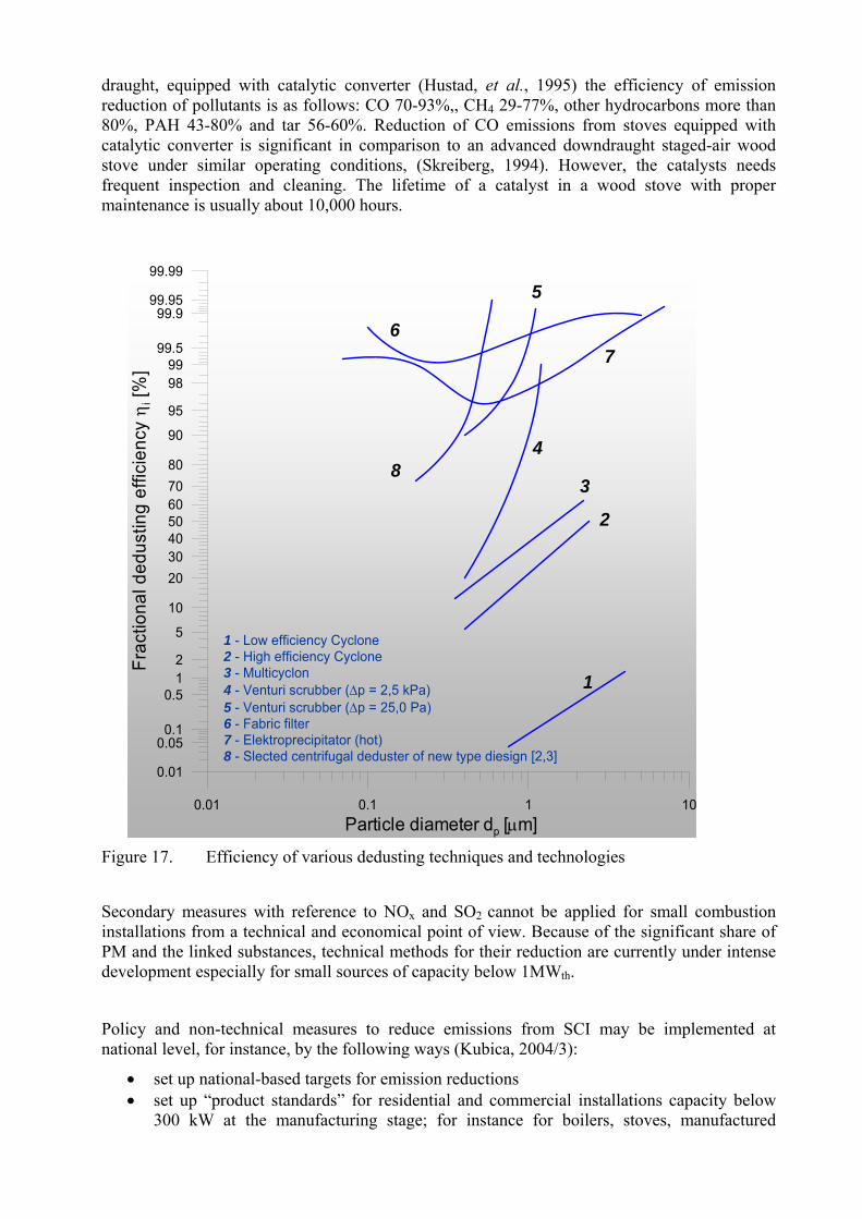
draught, equipped with catalytic converter (Hustad, et al., 1995) the efficiency of emission reduction of pollutants is as follows: CO 70-93%,, CH4 29-77%, other hydrocarbons more than 80%, PAH 43-80% and tar 56-60%. Reduction of CO emissions from stoves equipped with catalytic converter is significant in comparison to an advanced downdraught staged-air wood stove under similar operating conditions, (Skreiberg, 1994). However, the catalysts needs frequent inspection and cleaning. The lifetime of a catalyst in a wood stove with proper maintenance is usually about 10,000 hours.
0.01 0.1 1 10Particle diameter dp [μm]
0.01
0.050.1
0.512
5
10
20304050607080
90
95
9899
99.5
99.999.95
99.99
Frac
tiona
l ded
ustin
g ef
ficie
ncy η i
[%]
1
2
3
4
5
67
8
1 - Low efficiency Cyclone2 - High efficiency Cyclone3 - Multicyclon4 - Venturi scrubber (Δp = 2,5 kPa)5 - Venturi scrubber (Δp = 25,0 Pa)6 - Fabric filter7 - Elektroprecipitator (hot)8 - Slected centrifugal deduster of new type diesign [2,3]
Figure 17. Efficiency of various dedusting techniques and technologies
Secondary measures with reference to NOx and SO2 cannot be applied for small combustion installations from a technical and economical point of view. Because of the significant share of PM and the linked substances, technical methods for their reduction are currently under intense development especially for small sources of capacity below 1MWth.
Policy and non-technical measures to reduce emissions from SCI may be implemented at national level, for instance, by the following ways (Kubica, 2004/3):
• set up national-based targets for emission reductions • set up “product standards” for residential and commercial installations capacity below
300 kW at the manufacturing stage; for instance for boilers, stoves, manufactured
fireplaces. These standards should reach a high energy and “ecological” efficiency level. Establishing an obligatory certification system will be necessary.
• set up “product standards” for fuels that are used in residential and commercial sector at the manufacturing and/or market stage (voluntary agreements)
• set up a requirement for supervision (regular inspection) of boiler capacity above 15 kW (solid and liquid fuels)
• set up a requirement for chimney installations control due to heat energy production appliance and chimney co-operation with reference to the emission of at least standard gaseous emission (CO, NOx, dust and VOC); chimney sweeper supervision over residential and communal system heating
• set up “LEVs” for the installations capacity above 2 MWth or 5 MWth • introduction economic instruments to reduce emissions; for instance a fuel taxes,
subsidies, emission trading – for medium size installations, promotion-subsidies for SMI – solid and biomass fuels and combustion appliances for residential heating
• attitude behavioural change; for instance trough information campaign, education programs on each level of population, eco-labels, leaflets etc.
However, it should be noted that the new Directive 2005/32/EC on the eco-design of Energy-using Products (EuP), is a good step forward. The Directive does not introduce directly binding requirements for specific products, but does define conditions and criteria for setting, through subsequent implementing measures, requirements regarding environmentally relevant product characteristics and allows them to be improved quickly and efficiently. CONCLUSIONS Small combustion installations are not small emitters which is why is necessary to establish new policy, new control and monitoring systems on regional, national and European levels. But it is necessary to introduce economy systems for applying primary and secondary measures to reduce emissions from these sources.
The emission inventories from small combustion installation are still evaluated with large uncertainty. These uncertainties of emission data result from the uncertainties related to both the emission factors and the statistical information on the activities covered by small combustion installations. Activity data for fuels, mainly for coal fuels and biomass, for the sources covered here typically have higher uncertainties than those for other stationary combustion sources. The current international (and possibly a number of national) statistics do not represent this sector well but an improving collection and reporting data in this sector should be considered on national level. The uncertainty of emission factors from small combustion installation sources is a function of the combustion technique, calibration and sampling frequency of direct measurements, and how representative the tested installation is for the whole population of sources (often referred as a typical source). The uncertainty of emission factors from small combustion installation sources is a function of the combustion technique, calibration and sampling frequency of direct measurements, and how representative the tested installation is for the whole population of sources (often referred as a typical source). In addition some measurement standards and sampling systems used for small combustion installations were developed for large-scale installations. For that reason the typical range of the uncertainty of individual measurement for small combustion installations is greater than in larger installations. Emissions caused by combustion of solid fuels in particular, depend

on the combustion technique used, the type of installation and its maintenance, capacity and age. In addition also operation conditions such as load, the period of combustion cycle - start-up, steady state and shut down conditions, as well as quality of fuels and the stability of its properties play an important role
For this reason it is necessary to establish research programs that will be providing the data available to improve emission factors as well as to develop measurement methodology (mainly PM, PAH, PCDD/F and VOC, and heavy metals) and to develop knowledge about toxic emission from SCIs.

6. References APEG (The Airborne Particle Expert Group) (1999); “Source apportionment of airborne
particulate matter in the United Kingdom”; Prepared on behalf of the Department of the Environment, Transport and the Regions, the Welsh Office, the Scottish Office and the Department of the Environment (Northern Ireland)
Artjushenko N.M., “Heating of Private Houses” (1985); Kiev, 178 p. 1985 (in Rusia)
Baumbach G., Zuberbühler U., Struschka M., Straub D., Hein K.R.G. (1999); „Feinstaubuntersuchungen an Holzfeuerunge“; Teil 1: Bereich Hausbrand und Kleingewerbe. Institut für Verfahrenstechnik und Dampfkesselwesen, Report No. – 44-1999, Universtät Stuttgart. Juli 1999
Baart A., Berdowski J., van Jaarsveld J. and Wulffraat K., (1995); “Calculation of atmospheric deposition of contaminants on the North Sea”, TNO-MEP-R 95/138, Delft, The Netherlands
Berdowski J.J.M., Bass J., Bloos J.P.J., Visschedijk A.J.H., Zandveld P.Y.J., (1997/1); “The European Atmospheric Emission Inventory for Heavy Metals and Persistent Organic Pollutants”; Umweltforschungsplan des Bundesministers fur Umwelt, Naturchutz und Raktorsicherheit. Luftreinhaltung. Forschunbericht 104 02 672/03. TNO, Apeldorn, The Netherlands, 1997
Berdowski, J.J.M., Mulder, W., Veldt, C., Visschedijk, A.J.H., and Zandveld, P.Y.J. (1997/2): “Particulate matter emissions (PM10 - PM2.5 - PM0.1) in Europe in 1990 and 1993”; TNO-report, TNO_MEP - R 96/472
Bostrom Curt-Ake, (2002); “Emission Factors for Small Scale Combustors (Bio-Fuels). IVL, Sweden”; UN-ECE TFEIP Combustion and Industry Expert Panel Workshop on: ”Emissions from Small and Medium Combustion Plants”, Ispra, April 2002, Procc. No.I.02.87
Bryczkowski A., Kubica R. (2002); Inżynieria i Aparatura Chemiczna, 41, nr 3, 13, 2002
Bryczkowski A., Kubica R. (2002): Inżynieria i Aparatura Chemiczna; 41, nr 4, 14, 2002 (polish)
BUWAL (Bundesamt für Umwelt, Wald und Landschaft) (1995); „Emissionsfaktoren für Stationäre Quellen“; BUWAL, Bern
BUWAL (Bundesamt für Umwelt, Wald und Landschaft) (2001); „Massnahmen zur Reduktion von PM10-Emissionnen“; Schlussbericht, BUWAL Abteilung Luftreinhaltung und NIS, January, 2001
Caserini Stefano, (2004); Private Communication; Technical University Milano
Caserini S., Monguzzi A.M., Fracaroli A., Moretti M., Giudici A. (2003), Distribuzione delle emissioni di diossine in atmosfera in Lombardia: scenario attuale e trend per le principali sorgenti; 1 Convegno: Ingegneria e Chimica per l'Ambiente "POP: diffusione nell'ambiente, loro controllo e tecnologie di abbattimento" Milano, 26-27 Novembre, 2003; http://www.aidic.it/POP/convegno%20novembre%202003.htm
CEC (2003): “European energy and transport. Trends to 2030”; KO-AC-02-001-EN-C, European Commission, Directorate General for Energy and Transport, Luxembourg
CEPMEIP (2002): “Co-ordinated European Programme on Particulate Matter Emission Inventories, Projections and Guidance”; 2002,: http://www.air.sk/tno/cepmeip/
Chapter Combustion Plants as Point Sources -B111, EMEP/CORINAIR Atmospheric Emission Inventory Guidebook
CITEPA, (2003), “Wood Combustion in Domestic Appliances”; Final Background Document on the sector; 30.06.2003

Clement Associates Inc. (1998): Comparative potency approach for estimating the risk associated with exposure to mixtures of PAHs. US EPA Contract No. 68-02-4403. Farfax, VA: ICF-Clement Associates, 1998;
COM(2003) 423 final; “Proposal for a Directive of the European Parliament and of the Council relating to arsenic, cadmium, mercury, nickel and polycyclic aromatic hydrocarbons in ambient air”; Brussels, 16.07.2003
Compilation of Air Pollutant Emission Factors (AP-42) (1996), Volume 1: “Stationery Point and Planning and Standards”; Research triangle Park. North Carolina, 1996
Crowther M., (1997) CRE Group LTD., “Scoping study for the transfer of clean coal technology in the domestic and small industrial markets”; ETSU for DTI, Crown Copyright 1997
Czekalski B., Drodz W.; (2003); “Emission from oil and gas boilers – the results of investigation in Poland. Personal communicate”; EN-POL, Katowice, Poland, October 2003
Danihelka P., Kubica K., Volna Z., Dej M., Ocelka T., Grabiec R., (2001); „Emission of PCDD/F from small burning facilities”; Procc. of Conf. ”Dioxins in Industry and Environment”; Poland, Krakow, June 2001,46-54
Davies M., Rantall, T.D., Stokes B.J., Williamson F., (1992); “Characterisation of Trace Hydrocarbon Emissions from Coal Fired Appliances”; Final Report on Ecsc. Project No 7220-ED821, Report No. ENV/27
Determination of Mean Emission Factors as Representative Figures for Emission of Stuttgart – IVD (1996; Final Report to P&D. Project 29546364/ Emission Factors; 1996
Directive (2000); Directive 2000/76/EC, of the European Parliament and of the Council of 4 December 2000 on the incineration of the waste
Dreiseidler, A., Baumbach, G., Pregger, T., and Obermeier, A. (1999): „Studie zur Korngröβenverteilung (< PM10 und PM2.5) von Staubemissionen“; Forschungsbericht 297 44 853, i. A. Des Umweltbundesamtes Berlin, Germany (different UBA sources, partly personal communication, cited in this study)
EDC; Energy Data Centre; www.worldenergy.org
Emission Factors Manual PARCOPM-ATMOS (1993); “Emission Factors for Air Pollutants”; Final version – TNO Report 92-233/112322-24285, 1992, 1993
EMEP (2002); EMEP/CORINAIR Emission Inventory Guidebook – 3rd edition October, 2002; www.tfeip-secretariat.org
Energy for Tomorrow’s World- Acting Now!; www.worldenergy.org
EPA (Environmental Protection Agency) (1998a); Compilation of Air Pollutant Emission Factors, 5-th ed: EPA AP-42; United States Environmental Protection Agency. Research Triangle Park, North Carolina
EPA (Environmental Protection Agency) (1996); “Report on Revisions to 5th Edition AP-42 Section 1.10 Residential Wood Stoves”, pp.10/92, United States Environmental Protection Agency. Research Triangle Park, North Carolina, U.S.
EPA (Environmental Protection Agency) (1998b); “Compilation of Air Pollutant Emission Factors, Section 7.1, Residential Wood Combustion”, 5-th ed.: EPA AP-42. United States Environmental Protection Agency. Research Triangle Park, North Carolina, U.S.
Geueke K.J., Gessner A., Hiester E., Quaß U., Bröker G., (2000); “Elevated Emissions of Dioxine and Furanes from Domestic Single Stove Coal Combustion”; Organohalogen Compounds; vol. 46, pp 272 – 275, 2000
Grochowalski A; (2002), „Ambient air concentration and emission of dioxins in Poland”; and Grochwalski A., „Results of dioxins emission measurements from thermal processes in Poland

1996-2002”; Proc., of JRC Workshop on the Determination of Dioxins in Industrial Emissions; Brno, Czech Republic, 16-19 April, 2002, pp. 87
Hein K.R.G., Bemtgen J.M., EU (1998); “Clean technology – co-combustion of coal and biomass”; Fuel Processing Technology; 54, 1998, pp. 159-169
Hesling D., (2002); “Emission from stationary combustion sources smaller that 20kW in the Netherlands: methodology and emission factors”; UN-ECE TFEIP Combustion and Industry Expert Panel Workshop on: ”Emissions from Small and Medium Combustion Plants”, Ispra, April 2002, Procc. No.I.02.87
Hobson M., Thistlethwaite G., (2003); “Emission factors programme Task 7 – Review of Residential & Small-Scale Commercial Combustion Sources”; AEAT/ENV/R/1407, Issue 1
Houck J.E., Tiegs P., E., (1998); “Residential Wood Combustion – PM2.5 Emissions”; WESTAR PM2.5 Emission Inventory Workshop; Reno, Nevada, July 22-23, 1998
Houck J.E., Tiegs P., E., (1998/1); “Residential Wood Combustion Technology Review”. Volume 1.Technical Report; EPA-600/R-98-174a, December 1998
Houck, J.E., Goulet, J.M., Chow, J.C., Watson, J.G., and Pritchett, L.C. (1989) “Chemical characterization of emission sources contributing to light extinction”; In: Mathai, C.V. (ed.) Transaction, visibility and fine particles. Air & Waste Management Association, Pittsburgh, PA, pp. 145-158
Houck, J.E., Crouch, J., Huntley, R.H. (2001); “Review of Wood Heater and Fireplace Emission Factors”; Paper presented at the 10th Annual Emission Inventory Meeting, 30th April – 3rd May, 2001, Denver, CO
Hlawiczka S., Kubica K., Zielonka U., (2003); “Partitioning factor of mercury during coal combustion in low capacity domestic heating appliances”; The Science of the Total Environment; Elsevier; 312, 2003, 261-265
Houck, J. and Tiegs, P.E. (1998); “Residential Wood Combustion Technology Review” EPA-600/R-98-174 (Volume 1 and 2)
Hustad J. E., Skreiberg Ø., and Sønju O. K., (1995);“Biomass Combustion Research and Utilisation in IEA Countries, Biomass and Bioenergy”, vol. 9, Nos 1-5, 1995
Hughes E.E., and Tillman D.A., (1998); Biomass cofiring: status and prospects 1996; Fuel Proc. Techn. Vol. 54, pp. 127-142, 1998.
IPCC Special Report, Emission Scenarios, 2000
IIASA (International Institute for Applied Systems Analysis), 2004; “Results of the RAINS model developed at IIASA”; Laxenburg, Austria (www.iiasa.ac.at/rains)
Jaecker-Voirol J. (2000): VOC: volatile organic compounds – Formation and Emission, in Pollutants from Combustion, Ed. Ch. Vovelle, NATO Science Series, Vol. 547, Kulwer Academic Publishers, s. 241, 2000
Kakareka S., Kukharchyk T., Khomisch V., (2003); “Belarusian Contribution to EMEP”; Annual report 2002, Minsk-Moscow, January 2003”
Karasek F., Dickson L., (1987); Science, 237, 1987
Karcz A., Kubica K., Ściążko M.; “Fuel coke — an environment friendly alternative to coal. II CUSTNET Conference on Coal Research a Development through Collaboration in Europe”; Ostrawa, Republika Czeska, 2–4.09.1996
Karvosenoja, N. (2000; “Results of investigation in Finland. Personal communication”
Klimont Z., Cofala J., Bertok I., Amann M., Heyes Ch., and Gyarfas F. (2002; “Modelling Particulate Emissions in Europe; A Framework to Estimate Reduction Potential and Control Costs”; Interim Report IR-02-076, International Institute for Applied Systems Analysis (IIASA), Laxenburg, Austria (can be found on the Internet at: http://www.iiasa.ac.at/rains/reports/ir-02-076.pdf)

Kolar J., „Stickstoffoxide und Luftreinhaltung“; Springer Verlag Berlin, Heilderberg, New York, 1990
K.Kubica, M.Ściążko, et al., (1995);“Proposal of certification system of fuels for communal economy”; No 981/94/W-50/OA-PO-Ex/D Founded by Ministry of Environment; Report IChPW 2440/95 (Polish)
Kubica K., (1997/1): “Distribution of PAH generated in domestic fuels boilers”; Proc. of 9th International Conference on Coal Science; Essen, Niemcy, 7–12.09.1997
Kubica, K., Raińczak, J., Rzepa, S., Ściążko, M., (1997/2); „Influence of „biofuel” addition on emission of pollutants from fine coal combustion”, Proc. 4th Polish-Danish Workshop on Biofuels, Starbieniewo, 12-14 czerwca 1997/2
Kubica K., (1998); “The effect of coal combustion process in stable bed conditions on generation and distribution of PAHs”; Proc. of the II International Scientific Conference “Air Protection in theory & Application, 2-4 June, Szczyrk, 1998, s 339
Kubica K., Misztal M., (1997/3), “Promotion of Low Emission Coal Fired Boilers”; Report THERMIE B Action DIS-0715-95-UK, IChPW, Zabrze, March, 1997
Kubica K., Sciążko M. (1994); ”Correlation of coal properties to char, briquette, and utilization characteristics”; Int. Conf. “Production and Utilization of Ecological Fuels from East Central European Coals”, Praga, Republika Czeska, 31.10-1.11.1994
Kubica K., Ranczak J., Wilkosz K. (1999); Report ICHPW 2696/99 “Determination of non-metanic organic compounds emission factors for solid fuels (coal coke), gas and oil fire appliances”, Zabrze, 31.05.99 (Polish)
Kubica K., (2000), “Termochemical conversion of coal organic matter during its combustion in fixed bed”; Karbo, R.45, 9, s. 292, 2000 (Polish)
Kubica K. (2001/1): „Combustion of biomass in small capacity appliances – emission of pollutants”; Międzynarodowa Konferencja nt. „Odnawialne źródła energii u progu XXI wieku”; s. 419, Warszawa 2001, (Polish, abstract in English)
Kubica K. (2001/2): “Predicting coal quality influence on generation and emission of TOC, VOCs and PAHs during their combustion fixed bed furnaces”; Proc. of 17th International Symposium on Combustion Processes, s. 122, Poznań 24–27.09.2001
Kubica K., (2002/1); “Emission of Pollutants during Combustion of Solid Fuels and Biomass in Small Appliances”; UN-ECE TFEIP Combustion and Industry Expert Panel Workshop on: ”Emissions from Small and Medium Combustion Plants”, Ispra, April 2002, Procc. No.I.02.87
Kubica K., J. Rańczak J. (2003/3); “Co-firing of coal and biomass in mechanical great boilers”; Procc., of Int., Conf., Combustion of alternative fuels in power and cement industry, 20-21 February, 2003, Opole, Poland, pp. 81-97
Kubica K., et al. (2002/2); “Development of technologies for biomass utilization”, Report IChPW 1.03/2002 (Polish)
Kubica K. (2002/3): “Low emission coal boilers as alternative for oil and gas boilers for residential and communal sectors; Coal hasn’t to contaminate” Katalog ochrony środowiska – Ekoprofit nr 1 (61)/2002, Katowice, 2002 (Polish)
Kubica K., (2003/1); “Environment Pollutants from Thermal Processing of Fuels and Biomass”, and “Thermochemical Transformation of Coal and Biomass” in Termochemical Processing of Coal and Biomass; pp 145-232, ISBN 83-913434-1-3, Publication, Copyright by IChPW and IGSMiE PAN; Zabrze-Kraków; 2003, (Polish)
Kubica K., Ranczak J, Matuszek K., Hrycko P., Mosakowski S., Kordas T., “Emission of Pollutants from Combustion of Coal and Biomass and Its Co-firing in Small and Medium Size Combustion Installation “ (2003/2); 4th JOINT UNECE Task Force & EIONET Workshop on Emission Inventories and Projections in Warsaw, Poland, 22-24 September, 2003

Kubica K., Ściążko M., Raińczak J., (2003/3); “Co-firing biomass and coal”; XVII Conference Procc., of Conf., “Energy and energy resources in national economy” Zakopane, 5-8 October 2003, 297-307, (Polish)
Kubica K., Nowakowski D. and Nazimek D., (2003/4); “Influence of DESONOX-p catalyst on the emission of pollutants from combustion process of coal in fixed bed combustion appliances”; Procc. of Conference „Jumelage”, Zakopane, 25-30 IX 2003
Kubica K., (2003/5); Polish CSR, No 7 T09C 070 20 „Influence of DESONOX catalytic on solid fuels organic matter conversion during their combustion in fixed bed” (in Polish)
Kubica, (2003/6); Kubica K., “Persistent Organic Compounds, in particular dioxins and furans, from residential combustion to be a threat environment”, June 2003 IOS Warsaw, http://ks.ios.edu.pl/gef/doc/gf-pol-nip-r1.pdf ; in the project GEF/POL/01/004 on subject "Enabling activities to facilitate early action on the implementation of the Stockholm convention on persistent organic pollutants (POPs)";(Polish)
Kubica K., Paradiz B., Dilara P., Klimont Z., Kakareka S., Dębski B., (2004/1); “Small Combustion Installations”; Draft of Chapter for “Emission Inventory Guidebook” , 2004; www.tfeip-secretariat.org/unece.htm
Kubica K., Dilara P., Paradiž B. (2004/2); “Toxic Emissions from Solid Fuel Combustion in Small Residential Appliances”; Procc. 6th International Conference on Emission Monitoring CEM-2004, June 9-11, 2004; Milano, Italy; www.cem2004.it
Kubica K., (2004/3); “Study of policies and methods in order to limit emissions from domestic combustion of coal in the CC. Supervision of the start-up of the JRC facility for the determination of emissions from small sources”; Final Report Contract No 20850, 30.06.2004; JRC IES H04, Ispra Italy
Lammi K., Lehtonen E. and Timonen T. (1993); “Energiantuotannon hiukkaspäästöjen teknis-taloudelliset vähentämismahdollisuudet (Technical and economical alternatives to reduce particulate emissions from energy production)”; Helsinki, Finland, Ministry of the Environment, Report 120. 64 pp. (In Finnish with English summary)
Loibel W., Orthofer O., Winiwarter W. (1993); “Spatially disaggregated emission inventory for antrophogenic NMVOC emissions in Austria”; Atmospheric Environment, 27A, 16, pp. 2575-2590, 1993
Marutzky, R. and Seeger, K., (1999): „Energie aus Holz und anderer Biomasse“; ISBN 3-87181-347-8, DRW-Verlag Weinbrenner (ed.), Leinfelden-Echtlingen, Germany
Meier, E. and Bischoff, U. (1996); „Alkalische Emisisonsfaktoren beim Einsatz ballastreicher Braunkohlen in Vebrennunganlagen“; IfE Leipzig i.A des BMBF, Beitrag C2.2 des Verbundvorhabens SANA, in: Wissenschaftliches Begleitprogramm zur Sanierung der Atmmosphäre über den neuen Bundesländern, Abschlussbericht Band II
McElroy, M.W., Carr, R.C., Ensor, D.S., Markowski, G.R. (1982); “Size Distribution of Fine Particles from Coal Combustion”; Science, Vol. 215, No. 4528, 1 January 1982, pp. 13-19
Moche W., Thanner G. (1998); PCDD/F Emissions from Coal Combustion in Small Residential Plants; Organohalogen Compounds; Vol.37, 329-332, 1998
Nielsen M., Illerup J.B., Kristensen P.G., Jensen J., Jacobsen H.H., Johansen L., P., (2003); “Emission factors for CHP plants < 25MWe”; (2003); 4th JOINT UNECE Task Force & EIONET Workshop on Emission Inventories and Projections in Warsaw, Poland, 22-24 September, 2003
Nisbet I.C.T., LaGoy P.K. (1992): Toxic Equivalency Factor (TEFs) for PAHs. Regul. Toxicol. Pharmacol., R,16, s. 290, 1992;
NUTEK (1997); “Environmentally - Adapted Local Energy Systems”; Report 4733, Swedish Environmental Agency, Stockholm

Ohlström, M. (1998); “Energiantuotannon pienhiukkaspäästöt Suomessa (The fine particle emissions of energy production in Finland)”; Espoo, Finland, Technical Research Center of Finland, VTT Research Notes 1934. 114 pp. (In Finnish with English summary)
Olendrzynski K., Fudala J., Hlawiczka S., Cenowski S., Kachniarz M., Kargulewicz I., Debski B. Skoskiewicz J.(2002); “Emission Inventory of SO2, NO2, NH3, CO, PM, HMs, NMVOCs and POPs in Poland 2000”; UN-ECE – EMEP/Poland – Report/2002; IOS, Warszawa
Pacyna J.M., Pacyna E.G., (2001); “An assessment of global and regional emissions of trace metals to the atmosphere from anthropogenic sources worldwide”; Environ.Rev.2001, No 9 pp 269 - 298
Perry R.H., Green D.W., (1997); Chemical Engineers Handbook, Ed.7, Mc Grow-Hill, London, 1997
Pfeiffer F., Struschka, M., Baumbach, G. (2000); „Ermittlung der mittleren Emissionsfaktoren zur Darstellung der Emissiionsentwicklung aus Feuerungsanlagen im Bereich der Haushalte und Kleinverbraucher“; UBA-FB 295 46 36414/00, Umwelbundesamt, Berlin Mai 2000 (Germany, English abstract)
Struschka, M., Zuberbühler U., Dreiseidler A., Dreizler D., Baumbach, G. (2003); „Ermittlung und Evaluierung der Feinstaubemissionen aus Kleinfeurungsanlagen im Bereich der Haushalte und Kleinverbraucher sovie Ableitung von geeingenten Maßnahmen zur Emissionminderung“; UBA-FB 299 44 140, Umwelbundesamt, Berlin Juli 2003 (Germany, English abstract)
Pulles T., van Aardenne J., Tooly L., Rypdal K., (2001); “Good Practice Guidance for CLRTAP Emission Inventories”; European Topic Centre on Air and Climate Change (ETC/ACC), 7 November, 2001, www.emep.int or on the Internet site of the European Environment Agency http://reports.eea.eu.int/EMEPCORINAR/en
Quass U., Fermann M., Bröker G.; (2000);“The European Dioxin Emission Inventory - Stage II” Desktop studies and case studies”; Final Report 31.21. 2000; Volume 2, pp. 115-120, North Rhine Westphalia State Environment Agency
RDF, (2003); Refuse Derived Fuel, Current Practice And Perspectives (B43040/2000/306517/Mar/E3) Final Report Wrc., Ref: Co5087-4, July 2003
Ross A.B., Jones J.M., Chaiklangmuang S., Pourkahanian M., Williams A., Kubica K., Andersson J.T., Kerst M., Danihelka P. i Bartle K.D. (2002); “Measurement and prdiction of the emission of pollutants from the combustion of coal and biomass in a fixed bed furnace”; Fuel, 81, 5, pp 571, 2002
Skreiberg, Ø., 1994; “Advanced techniques for Wood Log Combustion”; Procc. From COMETT Expert Workshop on Biomass Combustion May 1994
Saanum et al, (1995); “Emissions from Biomass Combustion”, Norway Institute of Technology, 1995
Smith, K.R. (1987); “Biofuels, Air Pollution, and Health, A Global Review”; Plenum Press, New York, p. 452
Solid biofuels – Terminology, definitions and descriptions; (2003); CEN/TS 14588:2003
Spitzer, J., Enzinger, P., Fankhauser, G., Fritz, W., Golja, F., Stiglbrunner, R. (1998; „Emissionsfaktoren für Feste Brennstoffe“; Endbericht Nr.: IEF-B-07/98, Joanneum Research, Graz, December 1998, p. 50
Thanner G., Moche W., (2002); „Emission von Dioxine, PCBs und PAHs aus Kleinfeuerungen“; Umweltbundesamt, Federal Environment Agency – Austria, Monographien Band 153, Wien, 2002
The Air Quality Strategy for UK; 2000; “The Air Quality Strategy for England, Scotland, Wales and Northern Ireland”, Working Together for Clean Air, Cm 4548 January, 2000

Tullin C. and Johansson L. (2000). Particulate emissions from small-scale biomass combustion. Background paper for Nordic Seminar on Small Scale Wood Combustion, 17-18.2.2000, Naantali, Finland
UBA (Umweltbundesamt) (1989); „Luftreinhaltung’88, Tendenzzen – Probleme – Lösungen“, Federal Environmental Agency (Umweltbundesamt), Berlin, in Dreiseidler et al. 1999
UBA (Umweltbundesamt) (1998); „Schriftliche Mitteilung von Hr. Nöcker vom 01.09.1998, UBA II 4.6“; Federal Environmental Agency (Umweltbundesamt), Berlin, in Dreiseidler et al. 1999
UBA (Umweltbundesamt) (1998a); „Schatzung der Staubemissionen in Deutschland (Industrieprozesse, Kraftwerke und Fernheizwerke, industriefeuereungen)“; Schriftliche Mitteilung von Hr.Remus vom 09.2000. Federal Environmental Agency (Umweltbundesamt), Berlin
UBA (Umweltbundesamt) (1999a), “Various estimates of particulate emission factors and particle size distributions” by Federal Environmental Agency (Umweltbundesamt), Berlin, in Dreiseidler et al., 1999
UMEG (Gesellschaft für Umweltmessungen und Umwelterhebungen mbH) (1999); „Feinstaubuntersuchungen an Holzfeuerungen, Teil 2: Bereich Industriefeuerungen > 1 MW“, Institut für Verfahrenstechnik und Dampfkesselwesen, Report No – 44-1999, Universtät Stuttgart, July, 1999
UNEP Chemicals (2003); “Standardized Toolkit for Identification and Quantification of Dioxin and Furan Releases”; Geneva, Switzerland, 1st Edition May 2003
US EPA (1993); Provisional guidance for quantitative risk assessment of PAHs. US EPA/600/R-93/089;
Van Loo S., and Koppejan J. (2002); Handbook of Biomass Combustion and Co-firing., Twente University Press, Enschede, 2002
Van der Most, P.F.J., Veldt, C. (1992); “Emission Factors Manual PARCOM-ATMOS, Emission factors for air pollutants 1992, Final version”; TNO and Ministry of Housing, Physical Planning and the Environment, Air and Energy Directorate Ministry of Transport and Water Management: The Netherlands; Reference number 92-235; 1992
Williams A., Pourkashanian M., Jones J.M., Skorupska N., (2000); “Combustion and Gasification of Coal”, Taylor and Francis, New York, 2000
Williams A., Kubica K., Anderson J., Bartle K.D., Danihelka P., (2001), INCO-Copernicus Contr. No. ERB IC15-CT98-053: „Influence of co-combustion of coal and biomass on the emission of pollutants in domestic appliances”; Final Report 1999-2001
Winiwarter, W., Trenker, Ch., Höflinger, W. (2001); „Österreichische Emissionsinventur für Stau“; A study for Austrian Environmental Agency (Umwelbundesamt), Final Report, ARC Seibersdorf Research Report, ARC—S-0151, 121 p., September 2001
www.worldenergy.org
www.fireplaceast.com; Fireplaces East; Russo Products. Inc.
www.hef.com.pl
www.mikrofill.com; Mikrofill Systems Limited
www.metalerg.pl; METALERG s.c.
www.romotop.cz
www.zamer.com.pl
Zhang J., Smith K., Ma Y., Ye S., Jiang S., Qi W., Liu P., Khalil M., Rasmussen R., Thorneloe S., (2000); Greenhouse gases and other airborne pollutants from household stoves in China: a database for emission factors. Atmospheric Environment 34 (2000) 4537-4549

7. Biblography
Additional literature, which is related to combustion and emissions:
Ahuja, M.S., Paskind, J.J., Houck, J.E., and Chow, J.C. (1989); “Design of a study for the chemical and size characterization of particulate matter emissions from selected sources in California”, In: Watson, J.G. (ed.) Transaction, and receptor models in air resources management. Air & Waste Management Association, Pittsburgh, PA, pp. 145-158
Amann M, Bertok I, Cofala J, Gyarfas F, Heyes Ch, Klimont Z, Makowski M, Schöpp W, Shibayev S (1998); “Cost-effective control of acidification and ground-level ozone”; Brussels: European Communities, 131 p, ISBN 92-828-4346-7
Capros, et al., (1999); “European Energy and CO2 emission Trends to 2020”; PRIMES model v.2. Bulletin of Science, Technology and Society 19(6): 474-492
DIN 51603 (1992): „Flüssige Brennstofe“; Teil 1: Heizöl EL, Mindestanforderungen (1995); Teil: Heizöl L, T und M, Anforderungen an die Prüng (1992)
Draft Guidlines for Estimating and Reporting Emissions Data; GE02-31778; EB.AIR/GE.1/2002/7; www.emep.int or on the Internet site of the European Environment Agency http://reports.eea.eu.int/EMEPCORINAR/en
EA-4/02, (1999); Expression of the Uncertainty of Measurement in Calibration, EA-4/02, European co-operation for Accreditation, December 1999, www.european-accreditation.or
Flagan, R.C. and Seinfeld, J.H. (1988); “Fundamentals of air pollution engineering”; New Jersey, USA, Prentice-Hall Inc., pp. 542
Good Practice Guidance and Uncertainty Management in National Greenhouse Gas Inventories; UNFCCC for the Intergovernmental Panel on Climate Change (IPCC); 2000; http://www.ipcc-nggip.iges.or.jp
VDI (1982) Richtlinie 2297:Emissionsminderung; Ölbefeurte Dampf- und Heisßwassererzeurger; 1982

European Commission EUR 23214 EN – Joint Research Centre – Institute for Environment and Sustainability Title: Small combustion installations:Techniques, emissions and measures for its reduction Author(s): Krystyna Kubica, Bostjan Paradiz, Panagiota Dilara Luxembourg: Office for Official Publications of the European Communities 2007 – 59 pp. – 21 x 29.7 cm EUR – Scientific and Technical Research series – ISSN 1018-5593 ISBN 978-92-79-08203-0 DOI 10.2788/63329 Abstract This report gives an overview of the small combustion installations, i.e. fireplaces, stoves, boilers and combined head and power generators (CHP) which can be used at household or up to district level in order to generate heat, hot water, cooking, etc. Special emphasis is given to the emissions and emission reduction methods for such sources, which are only small in power, but have a high pollution potential. A detailed analysis of the combustion techniques for each source is also included, with link to the relevant emissions.

How to obtain EU publications Our priced publications are available from EU Bookshop (http://bookshop.europa.eu), where you can place an order with the sales agent of your choice. The Publications Office has a worldwide network of sales agents. You can obtain their contact details by sending a fax to (352) 29 29-42758.

The mission of the JRC is to provide customer-driven scientific and technical support for the conception, development, implementation and monitoring of EU policies. As a service of the European Commission, the JRC functions as a reference centre of science and technology for the Union. Close to the policy-making process, it serves the common interest of the Member States, while being independent of special interests, whether private or national.
LB
- NA
- 23214- EN- C