small hvac field and survey information
TRANSCRIPT
CALIFORNIA ENERGY
COMMISSION
Small HVAC Field and Survey Information
Summary of Background Research Results (product 4.3.1) Description of the Field Methods (product 4.4.1) Survey Method and Questionnaires: Small HVAC Onsite Survey Form (product 4.4.2) Functional Performance Test (product 4.4.2) Economizer Survey (product 4.4.2) Spot Power Measurement (product 4.4.2) KW Survey (product 4.4.2) (This item is located in the Additional Documents file)
TE
CH
NIC
AL
REP
OR
T
October 2003 500-03-082-A-23
Gray Davis, Governor

CALIFORNIA
ENERGY
COMMISSION
Prepared By: Architectural Energy Corporation Pete Jacobs, Lead Author Boulder, Colorado Managed By: New Buildings Institute Cathy Higgins, Program Director White Salmon, Washington CEC Contract No. 400-99-013 Prepared For: Donald Aumann, Contract Manager Nancy Jenkins, PIER Buildings Program Manager Terry Surles, PIER Program Director Robert L. Therkelsen Executive Director DISCLAIMER This report was prepared as the result of work sponsored by the
California Energy Commission. It does not necessarily represent the views of the Energy Commission, its employees or the State of California. The Energy Commission, the State of California, its employees, contractors and subcontractors make no warrant, express or implied, and assume no legal liability for the information in this report; nor does any party represent that the uses of this information will not infringe upon privately owned rights. This report has not been approved or disapproved by the California Energy Commission nor has the California Energy Commission passed upon the accuracy or adequacy of the information in this report.

ACKNOWLEDGEMENTS The products and outcomes presented in this report are part of the Integrated Design of Small Commercial HVAC Systems research project. The reports are a result of funding provided by the California Energy Commission’s Public Interest Energy Research (PIER) program on behalf of the citizens of California. Architectural Energy Corporation would like to acknowledge the support and contributions of the individuals below:
Program and Contract Management: Cathy Higgins, New Buildings Institute; Don Aumann, California Energy Commission.
Technical Advisory Group (TAG): Tudi Hassl of Portland Energy Conservation, Inc. (PECI), Jan Johnson of Southern California Edison, John Proctor of Proctor Engineering Group, Richard Lord of Carrier Corporation, Dr. Mark Modera of Carrier Aeroseal.
Architectural Energy Corporation Project Team: Pete Jacobs led the project, with AEC staff support from Dave Roberts, Tracy Phillips, Erik Jeanette, John Wood, Matthew Potts, Kosol Kiatreungwattana, Pablo Calderon-Rodriguez and Judie Porter. RLW Analytics as a subcontractor provided field testing and engineering support and statistical analysis, including contributions from Roger Wright, Matt Brost, Jeff Staller, Eric Swan, Amber Watkins and Stacia Okura. Eskinder Berhanu, Principal of Eskinder Berhanu Associates also provided field testing and engineering support.
Additional Support: Alan Cowan and Jeff Johnson of New Buildings Institute, project technical review and Design Guide review; Darren Goody of PECI, Design Guide Review.
PREFACE The Public Interest Energy Research (PIER) Program supports public interest energy research and development that will help improve the quality of life in California by bringing environmentally safe, affordable, and reliable energy services and products to the marketplace.
This document is one of 33 technical attachments to the final report of a larger research effort called Integrated Energy Systems: Productivity and Building Science Program (Program) as part of the PIER Program funded by the California Energy Commission (Commission) and managed by the New Buildings Institute.
As the name suggests, it is not individual building components, equipment, or materials that optimize energy efficiency. Instead, energy efficiency is improved through the integrated design, construction, and operation of building systems. The Integrated Energy Systems: Productivity and Building Science Program research addressed six areas:
Productivity and Interior Environments
Integrated Design of Large Commercial HVAC Systems
Integrated Design of Small Commercial HVAC Systems
Integrated Design of Commercial Building Ceiling Systems
Integrated Design of Residential Ducting & Air Flow Systems
Outdoor Lighting Baseline Assessment The Program’s final report (Commission publication #P500-03-082) and its attachments are intended to provide a complete record of the objectives, methods, findings and accomplishments of the Integrated Energy Systems: Productivity and Building Science Program. The final report and attachments are highly applicable to architects, designers, contractors, building owners and operators, manufacturers, researchers, and the energy efficiency community.
This attachment, “Small HVAC Field and Survey Information” (Attachment A-23), provides supplemental information to the program’s final report within the Integrated Design of Small Commercial HVAC Systems research area and includes the following reports:
1. Summary of Background Research Results. An overview of background research conducted in areas relevant to improving the installed efficiency of small HVAC systems through improved systems integration.
2. Description of the Field Methods. A PowerPoint document used to train the people who would be conducting field surveys of small package HVAC units in California commercial buildings.
3. Survey Method and Questionnaires. A series of forms and test protocols used by the project’s field staff when conducting site surveys of buildings with small package HVAC units. Includes an onsite survey form used when interviewing the building representative about occupancy history, schedule and other unobservable information; functional performance test protocol and procedures; economizer survey form used to record data about the site’s HVAC units; spot power measurement procedure; and kW survey form used to record the units’ kW measurements.

The Buildings Program Area within the Public Interest Energy Research (PIER) Program produced these documents as part of a multi-project programmatic contract (#400-99-413). The Buildings Program includes new and existing buildings in both the residential and the non-residential sectors. The program seeks to decrease building energy use through research that will develop or improve energy efficient technologies, strategies, tools, and building performance evaluation methods.
For other reports produced within this contract or to obtain more information on the PIER Program, please visit www.energy.ca.gov/pier/buildings or contact the Commission’s Publications Unit at 916-654-5200. All reports, guidelines and attachments are also publicly available at www.newbuildings.org/pier.

ABSTRACT The “Small HVAC Field and Survey Information” consists of three reports produced as a part of the Integrated Design of Small Commercial HVAC Systems project, one of six research elements in the Integrated Energy Systems: Productivity and Building Science Program. This program was funded by the California Energy Commission’s Public Interest Energy Research (PIER) Program.
This project conducted field surveys and short-term monitoring of packaged HVAC systems up to 10 tons per unit and identified problems that lead to poor system performance. This attachment consists of documents developed as part of the project’s early research tasks.
1. Summary of Background Research Results. An overview of background research conducted in areas relevant to improving the installed efficiency of small HVAC systems through improved systems integration.
2. Description of the Field Methods. A PowerPoint document used to train the people who conducted the field surveys of small package HVAC units in California commercial buildings.
3. Survey Method and Questionnaires. A series of forms and test protocols used by the project’s field staff when conducting site.
Small HVAC Onsite Survey Form. Interview questions used to identify occupancy history, schedules and other unobservable aspects of the buildings.
Functional Performance Test. An outline of procedures used for testing the units’ performance.
Economizer Survey. A form for recording data about the HVAC units and economizers.
Spot Power Measurement. An outline of the spot measurement procedure utilizing two techniques: phase-to-neutral and phase-to-phase.
KW Survey. A form for recording the units’ kW measurements.
Author: Pete Jacobs, Architectural Energy Corp.
Keywords: packaged HVAC system, economizer, spot power measurement, RTU, thermostat, damper, DX air conditioner, refrigerant charge
Integrated Energy Systems
Productivity & Building Science Program
A project of the State of California PIER Program
Element Four – Integrated Design of Small Commercial HVAC Systems
Background Research Summary Final August 15, 2002
Deliverable Number 4D4.3.1

NBI PIER Element Four Background Research Summary
Architectural Energy Corporation 1
INTRODUCTION The purpose of the background research task is to develop research questions pertaining to small commercial HVAC systems. Background research was conducted in areas relevant to improving the installed efficiency of small HVAC systems through improved systems integration. The background research activities fall into two general categories: 1. Market characterization, which is intended to gather information to better understand the
demographics of the buildings with small HVAC systems, and understand the market penetration of various types of small HVAC systems
2. Systems integration, which is intended to identify prior and future studies relating to systems integration issues in small HVAC systems.
MARKET CHARACTERIZATION The focus of Element 4 is small HVAC systems in new non-residential buildings in the State of California. The primary data resource for the market characterization study is the California Statewide Non-Residential New Construction (NRNC) database. This database was used to develop market characterization data relevant to this project.
NRNC Database The California NRNC database is a collection of 990 buildings statistically selected to represent the majority of statewide NRNC activity. The majority of the data come from about 880 on-site surveys conducted during impact evaluation studies of the SCE and PG&E 1994 and 1996 NRNC energy efficiency programs. These data were supplemented with thirty audits from the impact evaluation of the 1995 SDG&E NRNC program and additional on-site surveys designed to supplement the existing data. Participants in utility energy-efficiency programs are included, but are weighted according to their general representation in the population. The population was defined using a listing of new construction projects obtained from F. W. Dodge. The Dodge database seeks to list all new construction projects that are valued over $200,000 and are expected to start within 60 days. The data include renovations and expansions as well as entirely new buildings.1 These data were filtered to exclude projects not covered under Title 24. The population-weighted square footage distribution of audited sites in the NRNC database is shown by building type in Figure 1. These data are compared to estimates of new construction activity in 2001 supplied by the CEC.
1 The data is thought to cover over 95% of all projects that are competitively bid.

NBI PIER Element Four Background Research Summary
Architectural Energy Corporation 2
S h a re o f T o ta l N R N C M a rk e t
0
0 .0 5
0 .1
0 .1 5
0 .2
0 .2 5
0 .3
Office
Restau
rants
Retail
Food S
tores
Non-R
efrg W
hses
Refrg W
hse
Elem/S
cndry
Sch
ools
Colleg
es, U
nivers
ities
Hospit
als
Hotel/M
otel
Misc.
B u ild in g T y p e
Mar
ket S
hare
(% o
f tot
al S
F)
C E C P ro je c tio n sN R N C D a ta b a s e
Figure 1 – Estimates of NRNC Construction Activity by Building Type
Note, the market share distribution in the NRNC database and the CEC projections are fairly close in most important market categories. Notable exceptions are the Restaurant and Hotel/Motel sectors, which generally do not comprise a large fraction of the total NRNC activity.
During the audits, information on building physical characteristics such as types of lighting and plug load inventories, types and efficiency of HVAC equipment, insulation levels, and glazing properties were collected. Building occupants were interviewed to determine behavior characteristics such as occupancy schedules and equipment operation. The on-site data were used to develop DOE-2 building energy simulation models through an automated modeling process. Most building simulation models were calibrated to monthly billing data when the data were available.
The NRNC data represent the broad range of construction practices, climate zones and occupant behavior expected in a building population as diverse as the NRNC market. For example, the office segment contains a wide variety of buildings ranging from glass and steel skyscrapers to one-story wood frame buildings. Each site in the sample has a statistically derived sample weight and precision, expressing the relative representation of each building in the NRNC population, thus allowing the results obtained from simulations of each individual building to be projected to the population with a quantifiable level of precision.
NBI PIER Element Four Background Research Summary
Architectural Energy Corporation 3
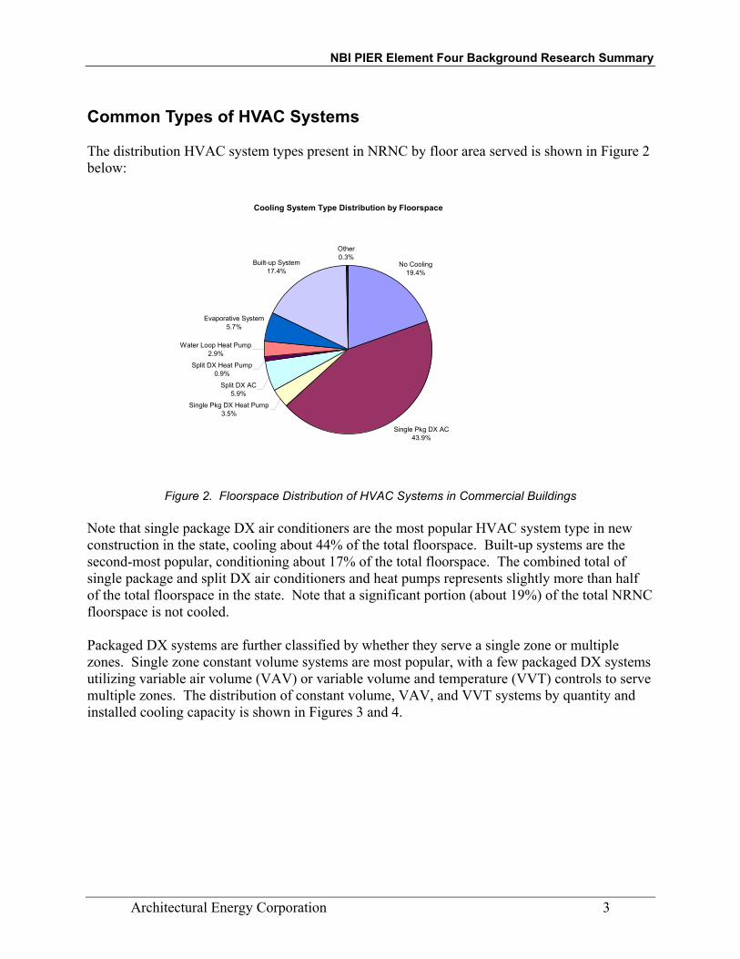
Common Types of HVAC Systems The distribution HVAC system types present in NRNC by floor area served is shown in Figure 2 below:
Cooling System Type Distribution by Floorspace
No Cooling19.4%
Single Pkg DX AC43.9%
Single Pkg DX Heat Pump3.5%
Split DX AC5.9%
Split DX Heat Pump0.9%
Water Loop Heat Pump2.9%
Evaporative System5.7%
Built-up System17.4%
Other0.3%
Figure 2. Floorspace Distribution of HVAC Systems in Commercial Buildings
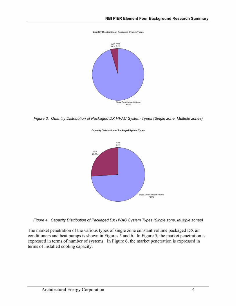
Note that single package DX air conditioners are the most popular HVAC system type in new construction in the state, cooling about 44% of the total floorspace. Built-up systems are the second-most popular, conditioning about 17% of the total floorspace. The combined total of single package and split DX air conditioners and heat pumps represents slightly more than half of the total floorspace in the state. Note that a significant portion (about 19%) of the total NRNC floorspace is not cooled. Packaged DX systems are further classified by whether they serve a single zone or multiple zones. Single zone constant volume systems are most popular, with a few packaged DX systems utilizing variable air volume (VAV) or variable volume and temperature (VVT) controls to serve multiple zones. The distribution of constant volume, VAV, and VVT systems by quantity and installed cooling capacity is shown in Figures 3 and 4.
NBI PIER Element Four Background Research Summary
Architectural Energy Corporation 4
Quantity Distribution of Packaged System Types
Single Zone Constant Volume95.3%
VAV4.6%
VVT0.1%
Figure 3. Quantity Distribution of Packaged DX HVAC System Types (Single zone, Multiple zones)
Capacity Distribution of Packaged System Types
Single Zone Constant Volume73.9%
VAV26.1%
VVT0.1%
Figure 4. Capacity Distribution of Packaged DX HVAC System Types (Single zone, Multiple zones)
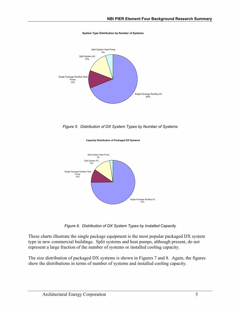
The market penetration of the various types of single zone constant volume packaged DX air conditioners and heat pumps is shown in Figures 5 and 6. In Figure 5, the market penetration is expressed in terms of number of systems. In Figure 6, the market penetration is expressed in terms of installed cooling capacity.
NBI PIER Element Four Background Research Summary
Architectural Energy Corporation 5
System Type Distribution by Number of Systems
Single Package Rooftop AC69%
Single Package Rooftop Heat Pump12%
Split System AC14%
Split System Heat Pump5%
Figure 5. Distribution of DX System Types by Number of Systems
Capacity Distribution of Packaged DX Systems
Single Package Rooftop AC74%
Single Package Rooftop Heat Pump10%
Split System AC13%
Split System Heat Pump3%
Figure 6. Distribution of DX System Types by Installed Capacity
These charts illustrate the single package equipment is the most popular packaged DX system type in new commercial buildings. Split systems and heat pumps, although present, do not represent a large fraction of the number of systems or installed cooling capacity. The size distribution of packaged DX systems is shown in Figures 7 and 8. Again, the figures show the distributions in terms of number of systems and installed cooling capacity.

NBI PIER Element Four Background Research Summary
Architectural Energy Corporation 6
HVAC Unit Size Distribution by Quantity
0%
5%
10%
15%
20%
25%
30%
1 2 3 4 5 6 7 10 12 15 20 25 30 40 50 75 100
Unit size (ton)
Estim
ated
NR
NC
Uni
tary
Sys
tem
Mar
ket S
hare
Figure 7. Distribution of Packaged DX System Size by Number of Systems
In terms of number of systems installed, the most popular packaged DX system size is 5 tons. Units between 1 and 10 tons represent close to 90% of the total unit sales in new buildings in California.
HVAC Unit Size Distribution by Capacity
0.00%
2.00%
4.00%
6.00%
8.00%
10.00%
12.00%
14.00%
16.00%
18.00%
20.00%
1 2 3 4 5 6 7 10 12 15 20 25 30 40 50 75 100
Unit size (ton)
Estim
ated
NR
NC
Uni
tary
Sys
tem
Mar
ket S
hare
Figure 8. Distribution of Packaged DX System Size by Installed Capacity
Figure 8 tells a slighting different story. The 10 ton unit is the most popular, in terms of installed cooling capacity, followed by the 5 ton unit. The cumulative distribution of packaged DX system capacity by size is shown in Figure 9.

NBI PIER Element Four Background Research Summary
Architectural Energy Corporation 7
Cumulative Capacity by Unit Size
0%
10%
20%
30%
40%
50%
60%
70%
80%
90%
100%
1 2 3 4 5 6 7 10 12 15 20 25 30 40 50 75 100
Unit Size
Perc
ent T
otal
Cap
acity
Figure 9. Cumulative Distribution of Packaged DX System Size by Installed Capacity
Note that units 10 tons and smaller represent about 58% of the total packaged DX cooling capacity in the state.
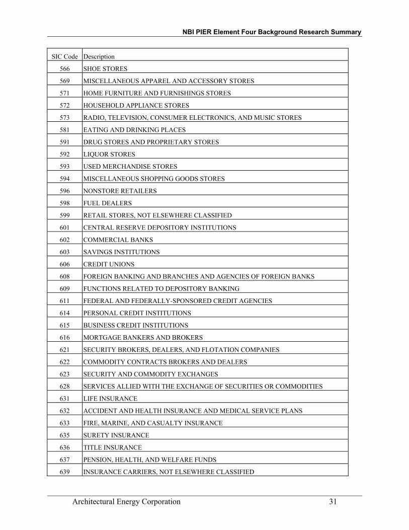
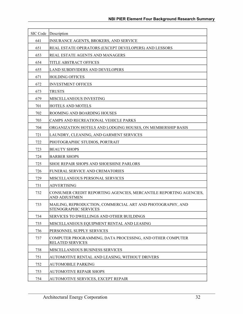
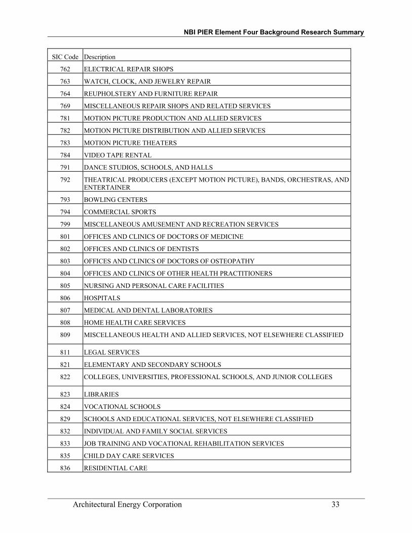
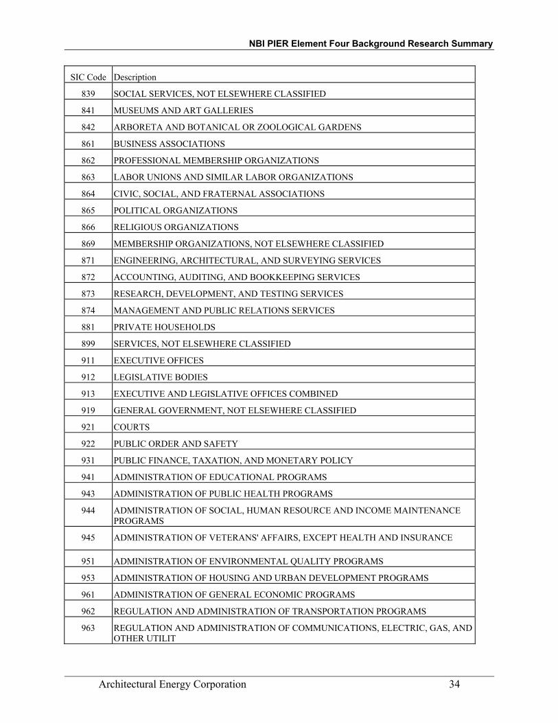
Buildings with Small HVAC Systems The NRNC database was queried to develop an understanding of the types and sizes of buildings using small HVAC systems, defined here as units 10 tons and smaller, and the number of units installed per building. Table 1 describes the penetration of small systems by building type, and the average number of systems per building on buildings that have small systems. The business types occupying these buildings (based on the three digit Standard Industrial Classification (SIC) code) is also shown. See Appendix B for a description of the business types represented by the three digit SIC code.

NBI PIER Element Four Background Research Summary
Architectural Energy Corporation 8
Table 1. Buildings with Small HVAC Systems
CEC Building Type SIC codes represented Have at least one small unit
Average Units/building (buildings with
at least one small system)
Colleges, Universities 822 34.0% 1.6
Elem/Scndry Schools 821, 824 72.7% 11.9
Food Stores 514 74.0% 2.6
Hospitals 806 51.9% 2.4
Hotel/Motel 701 56.2% 2.3
Large Office 162, 274, 291, 357, 367, 421, 431, 481, 481, 489, 511, 516, 602, 606, 614, 621, 632, 633, 637, 639, 641, 653, 672, 737, 737, 781, 806, 872, 873, 874, 919, 921, 922, 941, 971
53.9% 2.5
Large Retail 513, 521, 531, 566, 571, 573, 599 92.5% 7.0
Medical Clinic 801, 802 49.6% 2.0
Misc. 131, 201, 202, 203, 205, 208, 225, 242, 244, 251, 274, 283, 323, 335, 341, 344, 349, 354, 355, 356, 357, 362, 364, 365, 367, 369, 371, 384, 393, 399, 401, 431, 489, 495, 526, 721, 726, 731, 733, 737, 751, 753, 754, 781, 783, 792, 794, 799, 807, 821, 823, 832, 833, 835, 836, 841, 864, 866, 873, 919, 922, 953, 962, 964, 971
74.0% 4.0
Non-Refrg Whses 201, 203, 205, 208, 209, 227, 238, 242, 243, 265, 274, 308, 331, 353, 357, 359, 382, 421, 422, 504, 511, 581, 599, 861, 871, 919
71.4% 2.8
Restaurant 581 83.8% 3.2
Small Office 176, 203, 208, 209, 242, 267, 272, 273, 283, 289, 339, 349, 355, 357, 364, 366, 367, 371, 376, 384, 421, 431, 449, 458, 481, 484, 489, 494, 495, 513, 516, 527, 602, 603, 606, 614, 621, 639, 641, 653, 673, 733, 737, 781,832, 839, 861, 863, 866, 869, 871, 873, 899, 919, 921, 922, 941, 944, 962, 964
78.4% 6.2
Small Retail 501, 502, 504, 512, 513, 521, 525, 526, 565, 531, 533, 539, 554, 551, 564, 565, 566, 571, 573, 581, 592, 599, 784
91.8% 5.3
Note that the prevalence of small HVAC systems is fairly high in most building types, reflecting their high overall market penetration. Notable exceptions are colleges and universities, health care, and large offices. Hotels and motels often have small through the wall or packaged terminal air conditioners (PTAC) serving guest rooms, which were excluded from this study due to their low overall market penetration.
NBI PIER Element Four Background Research Summary
Architectural Energy Corporation 9
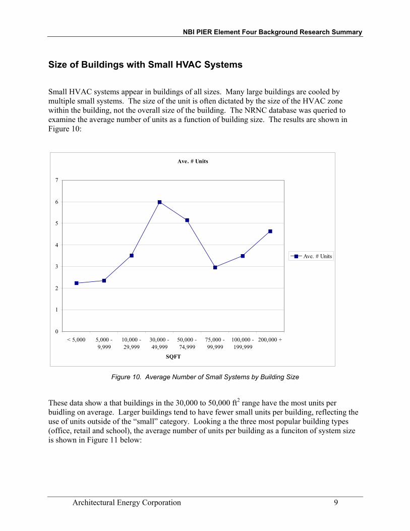
Size of Buildings with Small HVAC Systems
Small HVAC systems appear in buildings of all sizes. Many large buildings are cooled by multiple small systems. The size of the unit is often dictated by the size of the HVAC zone within the building, not the overall size of the building. The NRNC database was queried to examine the average number of units as a function of building size. The results are shown in Figure 10:
Ave. # Units
0
1
2
3
4
5
6
7
< 5,000 5,000 -9,999
10,000 -29,999
30,000 -49,999
50,000 -74,999
75,000 -99,999
100,000 -199,999
200,000 +
SQFT
Ave. # Units
Figure 10. Average Number of Small Systems by Building Size
These data show a that buildings in the 30,000 to 50,000 ft2 range have the most units per buidling on average. Larger buildings tend to have fewer small units per building, reflecting the use of units outside of the “small” category. Looking a the three most popular building types (office, retail and school), the average number of units per building as a funciton of system size is shown in Figure 11 below:

NBI PIER Element Four Background Research Summary
Architectural Energy Corporation 10
0
2
4
6
8
10
12
< 5,000 5,000 -9,999
10,000 -29,999
30,000 -49,999
50,000 -74,999
75,000 -99,999
100,000 -199,999
200,000 +
SQFT
Ave
# U
nits
OfficeRetail & WholesaleSchool
Figure 11. Average Number of Small Systems by Building Size in Offices, Retail, and Schools
Retail and wholesale stores up to 75,000 ft2 tend to have two units per building on average, reflecting the relatively simple zoning strategies typical of these building types. Offices and schools show increasing number of units up to the 50,000 to 75,000 ft2 size category, showing the use of multiple units to provide greater zoning capability in these buildings. The average number of units drop off above this size range, reflecting the use of fewer, larger units; some of which are outside the “small” size range.
Design Practices
Buildings are delivered to the owners using a variety of contracting mechanisms, including traditional Design-Bid-Build, Design/Build, Fast-track, and Negotiated Bid. A survey of architects was conducted by the California Board of Architectural Examiners (CBAE, 1999) to understand current and emerging trends in building delivery practices.
Table 2 below shows the response of architects to a survey questions regarding project delivery methods. The percentage of total revenue from architectural services categories are shown across the top, with the percentage of survey participants that selected each category are shown in each cell:

NBI PIER Element Four Background Research Summary
Architectural Energy Corporation 11
Table 2. Building Delivery Methods
Percent total revenue from architectural services
Delivery Process 0 – 25% 26 – 50% 51%+
Design-Bid-Build 39.9% 15.5% 44.6%
Design/Build 72.2% 13.4% 14.4%
Fast-track 82.0% 10.5% 7.3%
Negotiated Bid 56.3% 22.0% 21.7%
Project and Construction Management
67.2% 13.4% 19.4%
The survey concluded that while Design-Bid-Build is the most common builidng delivery processes, Design/Build will become more popular in the future.
A Nationwide survey of architects, engineers, and contractors was conducted by Air Conditioning and Refrigeration Technology Institute (ARTI) to get an understanding of the design practices used in the design of small (< 20,000 SF) buildings (Jacobs and Henderson, 2002). The survey concluded that manual methods (rules of thumb, simple nomographs, printed literature and forms) are the most popular design methods for all design decisions exept HVAC equipment sizing.
Table 3. Small Building Design Practices Design Decision Most Frequent Tool Used % of
Respondents Building Form, Siting, and Orientation
Previous experience, rule of thumb 33
Lighting and Daylighting Previous experience, rule of thumb 50 Envelope and Glazing Previous experience, rule of thumb 38 HVAC Equipment Sizing Manufacturers’ sizing software 51 HVAC Equipment Selection Manufacturers’ literature 47 Refrigeration System Design Manufacturers’ literature 49 Green Design and Materials Previous experience, rule of thumb 31 Energy Analysis and Code Compliance
Paper-based code compliance worksheets 27
Indoor Air Quality and Ventilation
ASHRAE Standard 62 37
Duct and pipe sizing Nomograph tools (such as the “Ductilator”) 57
The distribution of design methods for sizing HVAC systems is shown in Figure 12.

NBI PIER Element Four Background Research Summary
Architectural Energy Corporation 12
Manufacturers' sizingsoftware
51%
Building energysimulation software
7%
Manual J worksheet4%
Previous experience,rule of thumb
17%
Third party sizingsoftware
9%
Other12%
Figure 12. HVAC Sizing Design Methods
Note that HVAC equipment manufacturer-supplied software is the most commonly used tool for HVAC equipment sizing. Approximately two-thirds of the designers use some form of computerized sizing methods in the design of small commerical buildings. The study concluded that while most design decisions are made using simple design methods, the wide use of computerized design tools for HVAC system sizing opens the possibility for improved building systems integration using computerized sizing tools as the platform.
Energy Consumption
Simulation models were created for each building in the NRNC database using automated modeling software tied to the building characteristics data. The modeling software created a DOE-2.1E simulation model of each building, and the end-use energy consumption of each building was simulated. The energy consumption predicted for the population of buildings in the database was adjusted to reflect the CEC estimate of NRNC activity for the year 2001. The results are summarized in Table 4 as follows:
Table 4. Summary of NRNC floorspace and CEC New Construction Projections
Parameter Value Comments
Total floor space in NRNC database
233.2 million ft2 Sum of weighted floor area in database
Estimated 2001 new construction activity
155.1 million ft2 Excludes refrigerated warehouses
Adjustment factor 0.665
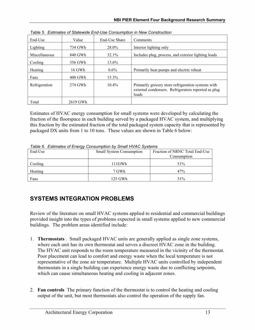
The estimated end-use energy consumption for the statewide NRNC population, based on 2001 construction activity is shown in Table 5 below:
NBI PIER Element Four Background Research Summary
Architectural Energy Corporation 13
Table 5. Estimates of Statewide End-Use Consumption in New Construction
End-Use Value End-Use Share Comments
Lighting 734 GWh 28.0% Interior lighting only
Miscellaneous 840 GWh 32.1% Includes plug, process, and exterior lighting loads
Cooling 356 GWh 13.6%
Heating 16 GWh 0.6% Primarily heat pumps and electric reheat
Fans 400 GWh 15.3%
Refrigeration 274 GWh 10.4% Primarily grocery store refrigeration systems with external condensers. Refrigerators reported as plug loads
Total 2619 GWh Estimates of HVAC energy consumption for small systems were developed by calculating the fraction of the floorspace in each building served by a packaged HVAC system, and multiplying this fraction by the estimated fraction of the total packaged system capacity that is represented by packaged DX units from 1 to 10 tons. These values are shown in Table 6 below:
Table 6. Estimates of Energy Consumption by Small HVAC Systems End-Use Small System Consumption Fraction of NRNC Total End-Use
Consumption
Cooling 111GWh 31%
Heating 7 GWh 47%
Fans 125 GWh 31%
SYSTEMS INTEGRATION PROBLEMS Review of the literature on small HVAC systems applied to residential and commercial buildings provided insight into the types of problems expected in small systems applied to new commercial buildings. The problem areas identified include:
1. Thermostats . Small packaged HVAC units are generally applied as single zone systems, where each unit has its own thermostat and serves a discreet HVAC zone in the building. The HVAC unit responds to the room temperature measured in the vicinity of the thermostat. Poor placement can lead to comfort and energy waste when the local temperature is not representative of the zone air temperature. Multiple HVAC units controlled by independent thermostats in a single building can experience energy waste due to conflicting setpoints, which can cause simultaneous heating and cooling in adjacent zones.
2. Fan controls The primary function of the thermostat is to control the heating and cooling output of the unit, but most thermostats also control the operation of the supply fan.

NBI PIER Element Four Background Research Summary
Architectural Energy Corporation 14
Thermostats used in small HVAC systems may not have the capability or may not be programmed to implement the fan control provisions of Title 24. Many of these thermostats are low-cost “residential” style units that provide manual control of the fan operation. If the fan controls are set to “auto,” the fans cycle with a call for heating or cooling, and fresh air is not continuously supplied to the zone. If the fan control is set to “on,” the fans may run continuously day and night, wasting fan energy during the unoccupied hours. The energy impact of fan control strategies also has significant interactions with the distribution system efficiency, since leaky and poorly insulated ductwork in unconditioned spaces can introduce significant unwanted heat gain to the zone during fan operation.
3. Economizers. Economizers in small systems can save significant energy, yet are notoriously unreliable. Economizer failures generally do not result in comfort problems, and therefore may go undetected by the occupants. Problems with economizers include incorrect installation of system components, incorrect placement of sensors, and poor quality components (dampers, linkages, etc.), and failed components. Economizer control settings for single point temperature or enthalpy economizers vary by climate zone due to variations in local humidity levels, and may not be set properly by the installer. Since many small systems (especially those under 5 tons) use single stage compressors with no capacity control, simultaneous operation of the economizer and the compressor (integrated economizer) may not be possible. Systems integration issues with economizers include HVAC unit sizing and part-load control, and indoor air quality.
4. System Sizing. Field research into HVAC system operation has indicated that many HVAC systems are significantly oversized, resulting in inefficient operation, reduced reliability due to frequent cycling of compressors, and poor humidity control. Oversized systems also result in wasted capital investment in both the HVAC unit and distribution system. System oversizing also affects the ability of the system to provide simultaneous economizer and compressor operation, and exacerbates problems with distribution system fan power, since larger units are supplied with larger fans. Oversizing can increase the impacts of poor distribution system design, since larger duct systems present more surface area for heat transfer and greater air leakage potential.
5. Distribution Systems. The efficiency of the HVAC system is a function of both the unit efficiency and distribution system efficiency. Field research into distribution system efficiency in small commercial systems has shown that the impacts of duct leakage and poor duct insulation can be significant. The distribution system efficiency is a function of duct design and installation practices, as well as architectural design decisions affecting environmental conditions imposed the duct system. Architectural design issues affecting distribution system efficiency include insulation placement (roof or ceiling), roof surface and color selection, and location of attic vents.
6. Condenser and Outdoor Air Entering Conditions. The ambient temperature conditions encountered at the condenser coil inlet and the outdoor air intake can be much different than
NBI PIER Element Four Background Research Summary
Architectural Energy Corporation 15
the ambient air temperature. Local air heating can be caused by solar energy absorbed by the roof surface and heat rejection from adjacent HVAC units. Air flow restrictions around the units may inhibit the dissipation of these heat sources into the surrounding air, thereby raising the air temperature around the units. Impacts of elevated air temperatures include reduced HVAC unit efficiency and increased outdoor air cooling loads. Roof top air temperatures are affected by architectural and mechanical design decisions such as roofing material selection, parapet and unit screen design, and HVAC unit placement.
7. Supply Fan Power. HVAC unit efficiency is calculated from ARI standard test and rating procedures, which use a standard assumption for supply fan power to determine overall unit efficiency. The actual fan power may be greater than the standard assumption, reducing the installed efficiency of the unit. Fan power in small HVAC systems is not regulated by Title 24, and can be a significant energy cost, especially in systems utilizing continuous ventilation through the HVAC system. The specific fan power of the units as installed will be measured and compared to the ARI standard values. The supply fan power issue is related to fan controls and system sizing.
8. Unit Air Flow. Field tests of air flow in small HVAC systems in residences have shown that the units are operating outside the manufacturers’ air flow rate recommendations. Additional studies on small commercial buildings have shown better compliance with manufacturers’ guidelines, but more research is needed to fully understand the nature of the problem in commercial buildings. Low air flow can result in reduced system efficiency and coil icing. High air flow can also result in excessive fan energy and insufficient moisture removal.
9. Refrigerant Charge. Field tests of residential split systems have indicated widespread problems with refrigerant charge. Most units are installed with improper charge, reducing efficiency and capacity of the HVAC units. There is growing evidence that similar problems exist with single package systems installed in commercial buildings. The impact of improper charge is exacerbated by system oversizing, improper air flow, and the use of fixed-orifice or capillary tube expansion devices instead of thermostatic expansion valves.
10. Maintenance Access. Small HVAC systems are generally mounted on the roof of commercial buildings, and are “out of sight and out of mind.” Maintenance access to these units can be limited, depending on unit layout, access to the roof by service personnel, architectural features and interior design. Efficient operation of small HVAC systems depends on regular maintenance, which can be difficult if access to the roof or unit service panels is blocked.
NBI PIER Element Four Background Research Summary
Architectural Energy Corporation 16
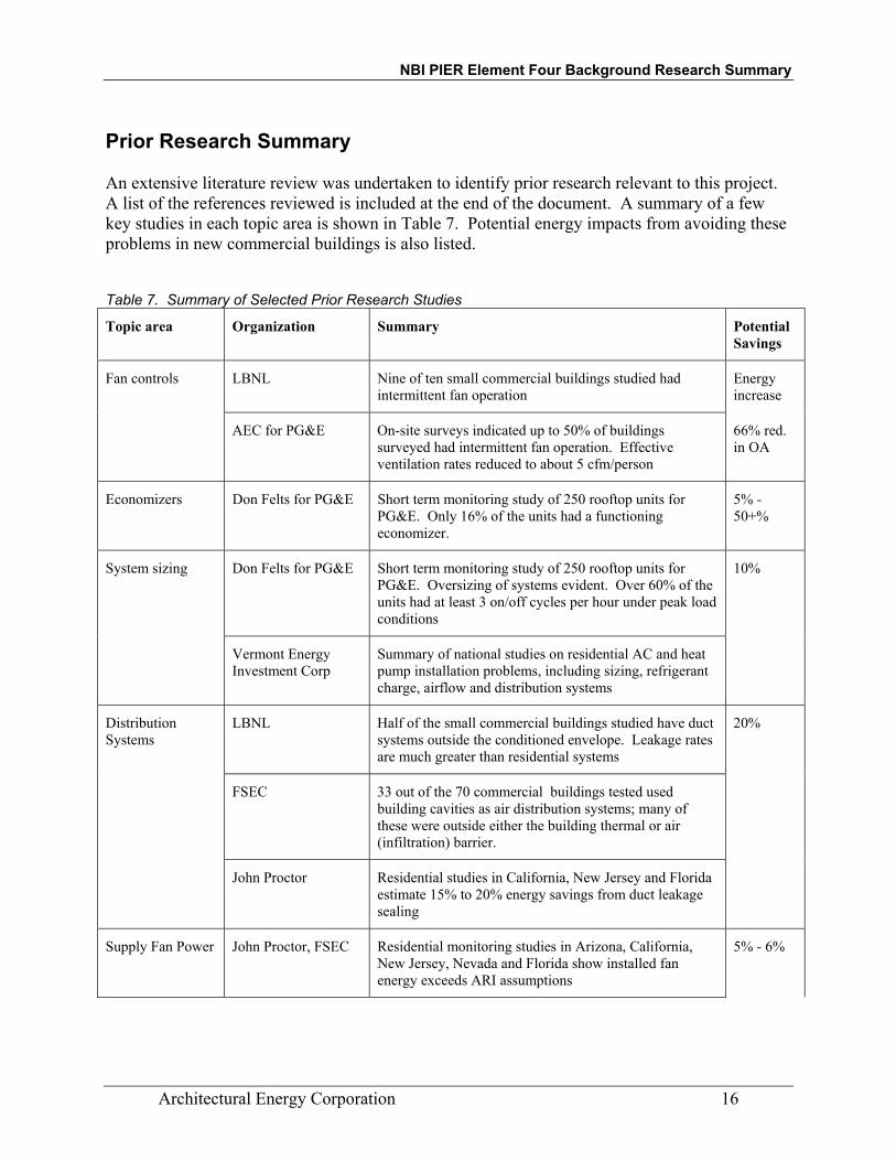
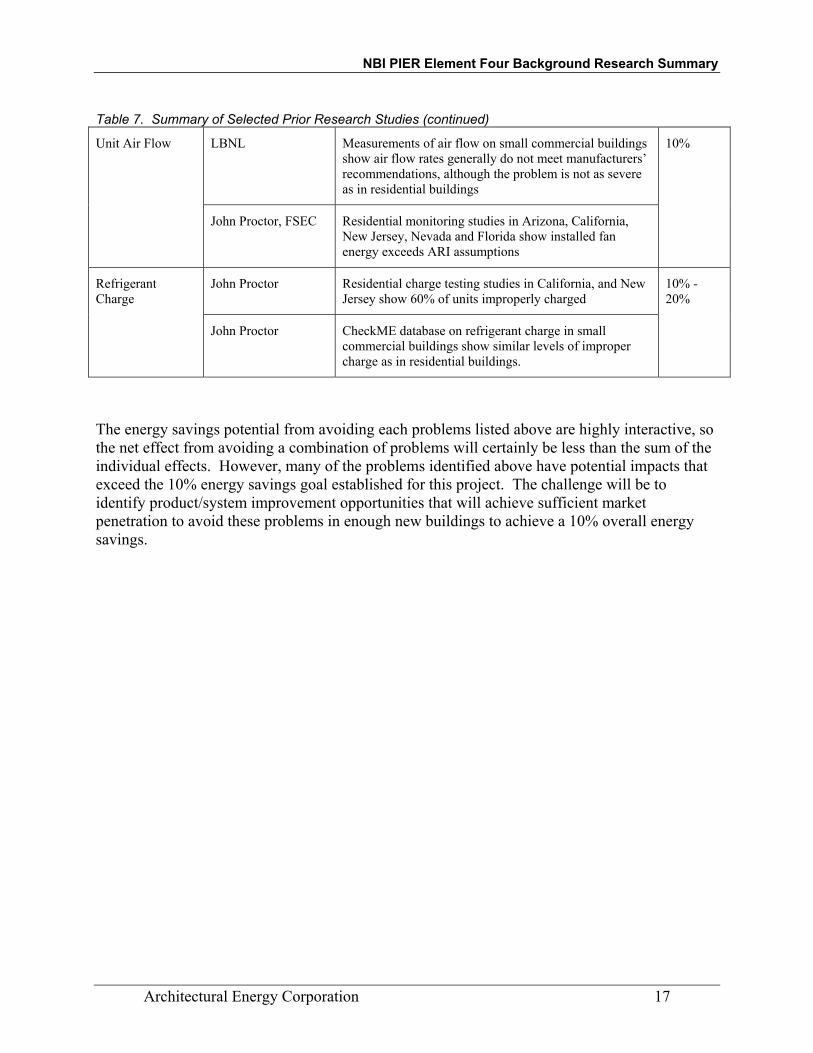
Prior Research Summary An extensive literature review was undertaken to identify prior research relevant to this project. A list of the references reviewed is included at the end of the document. A summary of a few key studies in each topic area is shown in Table 7. Potential energy impacts from avoiding these problems in new commercial buildings is also listed.
Table 7. Summary of Selected Prior Research Studies
Topic area Organization Summary Potential Savings
Fan controls LBNL Nine of ten small commercial buildings studied had intermittent fan operation
Energy increase
AEC for PG&E On-site surveys indicated up to 50% of buildings surveyed had intermittent fan operation. Effective ventilation rates reduced to about 5 cfm/person
66% red. in OA
Economizers Don Felts for PG&E Short term monitoring study of 250 rooftop units for PG&E. Only 16% of the units had a functioning economizer.
5% - 50+%
System sizing Don Felts for PG&E Short term monitoring study of 250 rooftop units for PG&E. Oversizing of systems evident. Over 60% of the units had at least 3 on/off cycles per hour under peak load conditions
10%
Vermont Energy Investment Corp
Summary of national studies on residential AC and heat pump installation problems, including sizing, refrigerant charge, airflow and distribution systems
Distribution Systems
LBNL Half of the small commercial buildings studied have duct systems outside the conditioned envelope. Leakage rates are much greater than residential systems
20%
FSEC 33 out of the 70 commercial buildings tested used building cavities as air distribution systems; many of these were outside either the building thermal or air (infiltration) barrier.
John Proctor Residential studies in California, New Jersey and Florida estimate 15% to 20% energy savings from duct leakage sealing
Supply Fan Power John Proctor, FSEC Residential monitoring studies in Arizona, California, New Jersey, Nevada and Florida show installed fan energy exceeds ARI assumptions
5% - 6%
NBI PIER Element Four Background Research Summary
Architectural Energy Corporation 17
Table 7. Summary of Selected Prior Research Studies (continued)
Unit Air Flow LBNL Measurements of air flow on small commercial buildings show air flow rates generally do not meet manufacturers’ recommendations, although the problem is not as severe as in residential buildings
10%
John Proctor, FSEC Residential monitoring studies in Arizona, California, New Jersey, Nevada and Florida show installed fan energy exceeds ARI assumptions
Refrigerant Charge
John Proctor Residential charge testing studies in California, and New Jersey show 60% of units improperly charged
10% - 20%
John Proctor CheckME database on refrigerant charge in small commercial buildings show similar levels of improper charge as in residential buildings.
The energy savings potential from avoiding each problems listed above are highly interactive, so the net effect from avoiding a combination of problems will certainly be less than the sum of the individual effects. However, many of the problems identified above have potential impacts that exceed the 10% energy savings goal established for this project. The challenge will be to identify product/system improvement opportunities that will achieve sufficient market penetration to avoid these problems in enough new buildings to achieve a 10% overall energy savings.

NBI PIER Element Four Background Research Summary
Architectural Energy Corporation 18
Current and Planned ActivitiesResearch, Market Transformation, and Resource Acquisition Several current and planned research projects that are related to this project have been identified. The project team will attempt to coordinate with these efforts to avoid duplication and leverage the research results. The key current and future projects are listed in Table 8 below:
Table 8. Summary of Related Current and Planned Research
Project / Researcher Sponsor Description
Duct sealing and refrigerant charge testing in small commercial buildings in Southern California. / John Proctor and Mark Modera
SCE Resource acquisition project will correct charge and seal ductwork in about 250 buildings this summer. No monitoring planned but pre/post charge and duct leakage data available.
LBNL Pier Project Element 4 - Low Energy Cooling. / Mark Modera
CEC Development of analytical procedures to model the impacts of distribution efficiency improvements. May involve adjustments to overall system efficiency and/or enhancements to EnergyPlus
2005 Update to Title 24 / Charles Eley et al.
CEC Updates to 2005 Title 24 non-residential standards will be studied. Topics include sizing, fan energy, refrigerant charge, T-bar ceilings and computer modeling
Codes and Standards Enhancement Initiative / Heshong – Mahone Group et al.
PG&E Updates to 2005 Title 24 non-residential standards will be studied. Topics include field verification procedures for tight ducts and economizers
NBI PIER Element Four Background Research Summary
Architectural Energy Corporation 19
APPENDIX A: BIBLIOGRAPHY
Brambley M., Pratt R., Chassin D., Katipamula S., and Hatley D. “Diagnostics for
Outdoor Air Ventilation and Economizers.” ASHRAE Journal. October 1998 Braun, James and Breuker, Mark. “Common Faults and Their Impacts for Rooftop Air
Conditioners.” HVAC&R Research. Vol. 4. No. 3. July 1998
Braun, James and Breuker, Mark. “Evaluating the Performance of a Fault Detection and Diagnostic System for Vapor Compression Equipment.” HVAC&R Research. Vol. 4. No. 4. October 1998
Breuker M., Rossi T., and Braun J. “Smart Maintenance for Rooftop Units.” ASHRAE
Journal. November 2000. Building and Appliance Efficiency Office of the Energy Efficiency and Local Assistance
Division of the California Energy Commission. “Package Rooftop Economizer Study.” Building Energy Efficiency Standards.
California Board of Architectural Examiners. “Trends in Practice Report,” CBAE, Sacramento, CA 1999. Consortium for Energy Efficiency. “Specification of Energy-Efficient Installation and
Maintenance Practices for Residential HVAC Systems.” Consortium for Energy Efficiency. “Guidelines for Energy Efficient Commercial Unitary
HVAC Systems,” Consortium for Energy Efficiency, Boston MA 2001 Consortium for Energy Efficiency. “White Paper for the Guidelines for Energy Efficient
Commercial Unitary HVAC Systems,” Consortium for Energy Efficiency, Boston MA 2001
Delp W., Matson N., Tschudy E., Modera M., and Diamond R. “Field Investigation of
Duct System Performance in California Light Commercial Buildings.” Lawrence Berkeley National Laboratory report No. 40102.
Don Felts Energy Consultant. “Roof Top Unit Economizer Feasibility Study.” Prepared
for Pacific Gas and Electric Company. August 25, 2000. Eley Associates. “Assembly Bill 970 Building Energy Efficiency Standards: Split
Systems Space Cooling Refrigerant Charge and Airflow Measurement.” Prepared for the California Energy Commission. March 20, 2001.

NBI PIER Element Four Background Research Summary
Architectural Energy Corporation 20
Felts, Don. “Roof Top Unit Technical Potential Assessment.” Pacific Gas and Electric Company. 2001
Felts, Don and Bailey, Patrick. “The State of Affairs – packaged Cooling Equipment in
California.” ACEEE 2000. Gartland L., Konopaski S., and Akbari H. “Modeling the Effects of Reflective Roofing.”
Ernest Orlando Lawrence Berkeley National Laboratory. August 1996. Haves P., Salsbury T., and Wright J., “Condition Monitoring in HVAC
Subsystems Using First Principles Models.” ASHRAE Transactions: Symposia. 1996.
Henderson, H.I. “Simulating Combines Thermostat, Air conditioner, and Building
Performance in a House.” ASHRAE Transactions. Vol 98. Part 1 1992 Herzog, Peter and LaVine, Lance. “Identification and Quantification of the Impact of
Improper Operation of Midsize Minnesota Office Buildings on Energy Use: A Seven Building Case Study.” ACEEE 1992
Hewett M., Bohac D., Landry R., Dunsworth T., Englander S., and Peterson G.
“Measured Energy and Demand Impacts of Efficiency Tune-ups for Small Commercial Cooling Systems.” ACEEE 1992.
Houghton, David. “Operating and Maintaining Rooftop Air-Conditioning Units.”
E source. January 1997. James, P., Cummings, J.E., Sonne, J., Vieira, R., and Klongerbo, J. “The Effect of
Residential Equipment Capacity on Energy Use, Demand, and Run-Time.” 2001 http://www.fsec.ucf.edu/~bdac/pubs/PF328/capacity.htm
Jacobs, P. and Henderson, H. “State-of-the-Art Review: Whole Building, Building Envelope, and HVAC Component and System Simulation and Design Tools,” ARTI-21CR-605-30010-30020-01. Air Conditioning and Refrigeration Technology Institute, Arlington, VA. 2002.
Jerkins, Virginia. “Heat Pump Study: Tricks of the Trade That Can Pump Up Efficiency.”
Home Energy. March/April 1996. Jump, D., Walker, I., and Modera, M. “Field Measurements of Efficiency and Duct
Retrofit Effectiveness in Residential Forced air Distribution Systems.” ACEEE Summer Study. August 1996

NBI PIER Element Four Background Research Summary
Architectural Energy Corporation 21
Katipamula S., Pratt R., Chassin D., Taylor T., Gowri K., and Brambley M. “Automated Fault Detection and Diagnostics for Outdoor-Air Ventilation Systems and Economizers: Methodology and Results from Field Testing.” ASHREA Transactions 1999, Vol. 105, Pt. 1
Kopko, William and Hibberd, Douglas. “Design of a High-Efficiency Rooftop Air
Conditioner.” ACEEE 1994 Krakow K., Zhao F., and Muhsin A. “Economizer Control.” ASHRAE Transactions 2000.
Vol. 106, Pt 2. Lunneberg, Tom. “When Good Economizers Go Bad: Keeping This Air-Side Energy
Saver on the Upside.” E source. ER-99-14. September 1999. Modera, Mark. “Two Favorite Test Methods, By the Book.” Home Energy Online.
September/October 1993. Modera, M., Dickerhoff, D., Nilssen, O., Duquette, H., and Geyselaers, J. “Residential
Field Testing of an Aerosol-Based Technology for Sealing Ductwork.” ACEEE. 1996
Moujaes, Samir and Brickman, Richard. “Effect of a Radiant Barrier on the Cooling Load of a
Residential Application in a Hot and Arid Region: Attic Duct Effect.” HVAC&R Research. Vol. 4. No. 3. July 1998.
Neal, Leon. “Air Conditioner Efficiency in the Real World.” Home Energy. May/June
1992 Peterson, George and Proctor, John. “Effects of Occupant Control, System Parameters,
and Program Measures on Residential Air Conditioner Peak Loads.” ACEEE. 1998.
Proctor Engineering group, LTD. “Support Documentation for John Proctor’s Comments
on the Central AC and heat Pump NOPR.” December, 2000. Proctor, John. “An Ounce of Prevention: Residential Cooling Repairs.” Home Energy.
May/June 1991. http://hem.dis.anl.gov/eehem/93/930912.htm Proctor, John and Parker, Danny. “Hidden Power Drains: Trends in Residential Heating
and Cooling Fan Watt Power Demand.” 2001. http://www.fsec.ufc.edu/%7Edbac/pubs/pf361/pf361/html
Rossi, Todd and Braun, James. “A Statistical, Rule-Based Fault Detection and
Diagnostic Method for Vapor Compression Air Conditioners.” HVAC&R Research. Vol. 3. No. 1. January 1997
NBI PIER Element Four Background Research Summary
Architectural Energy Corporation 22
Sherman, M.H. and Wilson, D.J. “Relating Actual and Effective Ventilation in Determining Indoor Air Quality” Building and Environment, Vol. 21. No. ¾. pp. 135-144. 1986.
Shugars J., Coleman P., Payne C., and McGrory L. “Bridging the Efficiency Gap:
Commercial Packaged Rooftop Air Conditioners.” ACEEE 2000. Silver, S., Fine, P., and Rose, F. “Performance Monitoring of DX Rooftop cooling
Equipment.” Energy Engineering. Vol. 87, No. 5. 1990 Texas Utilities. “Measurements and Verification Guidelines for Duct Sealing Measures.”
TXU Measurement and Verification Guidelines. Wilcox, Bruce and Hunt, Marshall. “Comparison of CHEERS Energy Use Predictions
with Actual Utility Bills." ACEEE 1998 Summer Study. June 29, 1998. Wray C., Matson N., and Sherman M. “Whole-House Ventilation Strategies to Meet
Proposed Standard 62.2: Energy Cost Considerations.” ASHRAE Transactions 2000. Vol. 106. Pt. 2.
Xu, T., Modera, M., and Carrie, R. “Performance Diagnostics of Thermal distribution
Systems in Light Commercial Buildings.” ACEEE. 2000.

NBI PIER Element Four Background Research Summary
Architectural Energy Corporation 23
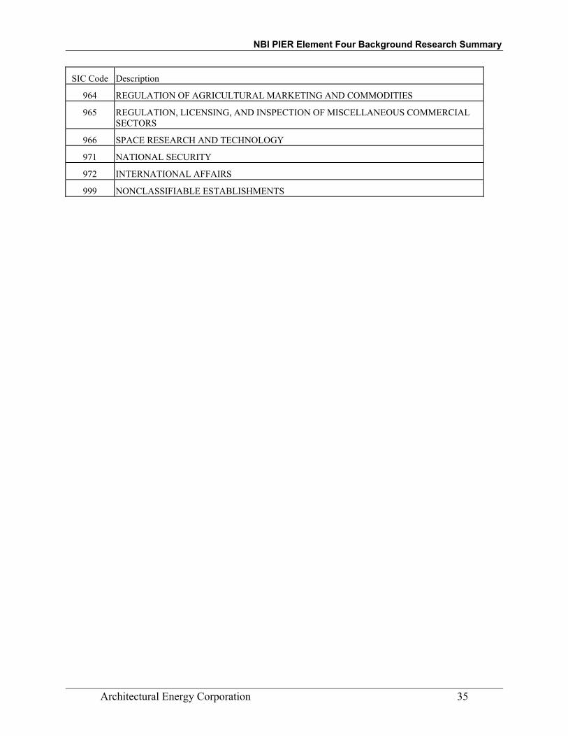
APPENDIX B: STANDARD INDUSTRIAL CLASSIFICATION
SIC Code Description
101 IRON ORES
102 COPPER ORES
103 LEAD AND ZINC ORES
104 GOLD AND SILVER ORES
106 FERROALLOY ORES, EXCEPT VANADIUM
108 METAL MINING SERVICES
109 MISCELLANEOUS METAL ORES
122 BITUMINOUS COAL AND LIGNITE MINING
123 ANTHRACITE MINING
124 COAL MINING SERVICES
131 CRUDE PETROLEUM AND NATURAL GAS
132 NATURAL GAS LIQUIDS
138 OIL AND GAS FIELD SERVICES
141 DIMENSION STONE
142 CRUSHED AND BROKEN STONE, INCLUDING RIPRAP
144 SAND AND GRAVEL
145 CLAY, CERAMIC, AND REFRACTORY MINERALS
147 CHEMICAL AND FERTILIZER MINERAL MINING
148 NONMETALLIC MINERALS SERVICES, EXCEPT FUELS
149 MISCELLANEOUS NONMETALLIC MINERALS, EXCEPT FUELS
152 GENERAL BUILDING CONTRACTORS-RESIDENTIAL BUILDINGS
153 OPERATIVE BUILDERS
154 GENERAL BUILDING CONTRACTORS-NONRESIDENTIAL BUILDINGS
161 HIGHWAY AND STREET CONSTRUCTION, EXCEPT ELEVATED HIGHWAYS
162 HEAVY CONSTRUCTION, EXCEPT HIGHWAY AND STREET CONSTRUCTION
171 PLUMBING, HEATING AND AIR-CONDITIONING
172 PAINTING AND PAPER HANGING
173 ELECTRICAL WORK
174 MASONRY, STONEWORK, TILE SETTING, AND PLASTERING
175 CARPENTRY AND FLOOR WORK
176 ROOFING, SIDING, AND SHEET METAL WORK
NBI PIER Element Four Background Research Summary
Architectural Energy Corporation 24
SIC Code Description
177 CONCRETE WORK
178 WATER WELL DRILLING
179 MISCELLANEOUS SPECIAL TRADE CONTRACTORS
201 MEAT PRODUCTS
202 DAIRY PRODUCTS
203 CANNED, FROZEN, AND PRESERVED FRUITS, VEGETABLES, AND FOOD SPECIALTIES
204 GRAIN MILL PRODUCTS
205 BAKERY PRODUCTS
206 SUGAR AND CONFECTIONERY PRODUCTS
207 FATS AND OILS
208 BEVERAGES
209 MISCELLANEOUS FOOD PREPARATIONS AND KINDRED PRODUCTS
211 CIGARETTES
212 CIGARS
213 CHEWING AND SMOKING TOBACCO AND SNUFF
214 TOBACCO STEMMING AND REDRYING
221 BROADWOVEN FABRIC MILLS, COTTON
222 BROADWOVEN FABRIC MILLS, MANMADE FIBER AND SILK
223 BROADWOVEN FABRIC MILLS, WOOL (INCLUDING DYEING AND FINISHING)
224 NARROW FABRIC AND OTHER SMALLWARES MILLS: COTTON, WOOL, SILK, AND MANMADE FIBER
225 KNITTING MILLS
226 DYEING AND FINISHING TEXTILES, EXCEPT WOOL FABRICS AND KNIT GOODS
227 CARPETS AND RUGS
228 YARN AND THREAD MILLS
229 MISCELLANEOUS TEXTILE GOODS
231 MEN'S AND BOYS' SUITS, COATS, AND OVERCOATS
232 MEN'S AND BOYS' FURNISHINGS, WORK CLOTHING, AND ALLIED GARMENTS
233 WOMEN'S, MISSES', AND JUNIORS' OUTERWEAR
234 WOMEN'S, MISSES', CHILDREN'S, AND INFANTS' UNDERGARMENTS
235 HATS, CAPS, AND MILLINERY
236 GIRLS', CHILDREN'S, AND INFANTS' OUTERWEAR

NBI PIER Element Four Background Research Summary
Architectural Energy Corporation 25
SIC Code Description
237 FUR GOODS
238 MISCELLANEOUS APPAREL AND ACCESSORIES
239 MISCELLANEOUS FABRICATED TEXTILE PRODUCTS
241 LOGGING
242 SAWMILLS AND PLANING MILLS
243 MILLWORK, VENEER, PLYWOOD, AND STRUCTURAL WOOD MEMBERS
244 WOOD CONTAINERS
245 WOOD BUILDINGS AND MOBILE HOMES
249 MISCELLANEOUS WOOD PRODUCTS
251 HOUSEHOLD FURNITURE
252 OFFICE FURNITURE
253 PUBLIC BUILDING AND RELATED FURNITURE
254 PARTITIONS, SHELVING, LOCKERS, AND OFFICE AND STORE FIXTURES
259 MISCELLANEOUS FURNITURE AND FIXTURES
261 PULP MILLS
262 PAPER MILLS
263 PAPERBOARD MILLS
265 PAPERBOARD CONTAINERS AND BOXES
267 CONVERTED PAPER AND PAPERBOARD PRODUCTS, EXCEPT CONTAINERS AND BOXES
271 NEWSPAPERS: PUBLISHING, OR PUBLISHING AND PRINTING
272 PERIODICALS: PUBLISHING, OR PUBLISHING AND PRINTING
273 BOOKS
274 MISCELLANEOUS PUBLISHING
275 COMMERCIAL PRINTING
276 MANIFOLD BUSINESS FORMS
277 GREETING CARDS
278 BLANKBOOKS, LOOSELEAF BINDERS, AND BOOKBINDING AND RELATED WORK
279 SERVICE INDUSTRIES FOR THE PRINTING TRADE
281 INDUSTRIAL INORGANIC CHEMICALS
282 PLASTICS MATERIALS AND SYNTHETIC RESINS, SYNTHETIC RUBBER, CELLULOSIC AND OTHER
283 DRUGS
284 SOAP, DETERGENTS, AND CLEANING PREPARATIONS; PERFUMES, COSMETICS, AND OTHER TOIL

NBI PIER Element Four Background Research Summary
Architectural Energy Corporation 26
SIC Code Description
285 PAINTS, VARNISHES, LACQUERS, ENAMELS, AND ALLIED PRODUCTS
286 INDUSTRIAL ORGANIC CHEMICALS
287 AGRICULTURAL CHEMICALS
289 MISCELLANEOUS CHEMICAL PRODUCTS
291 PETROLEUM REFINING
295 ASPHALT PAVING AND ROOFING MATERIALS
299 MISCELLANEOUS PRODUCTS OF PETROLEUM AND COAL
301 TIRES AND INNER TUBES
302 RUBBER AND PLASTICS FOOTWEAR
305 GASKETS, PACKING, AND SEALING DEVICES AND RUBBER AND PLASTICS HOSE AND BELTING
306 FABRICATED RUBBER PRODUCTS, NOT ELSEWHERE CLASSIFIED
308 MISCELLANEOUS PLASTICS PRODUCTS
311 LEATHER TANNING AND FINISHING
313 BOOT AND SHOE CUT STOCK AND FINDINGS
314 FOOTWEAR, EXCEPT RUBBER
315 LEATHER GLOVES AND MITTENS
316 LUGGAGE
317 HANDBAGS AND OTHER PERSONAL LEATHER GOODS
319 LEATHER GOODS, NOT ELSEWHERE CLASSIFIED
321 FLAT GLASS
322 GLASS AND GLASSWARE, PRESSED OR BLOWN
323 GLASS PRODUCTS, MADE OF PURCHASED GLASS
324 CEMENT, HYDRAULIC
325 STRUCTURAL CLAY PRODUCTS
326 POTTERY AND RELATED PRODUCTS
327 CONCRETE, GYPSUM, AND PLASTER PRODUCTS
328 CUT STONE AND STONE PRODUCTS
329 ABRASIVE, ASBESTOS, AND MISCELLANEOUS NONMETALLIC MINERAL PRODUCTS
331 STEEL WORKS, BLAST FURNACES, AND ROLLING AND FINISHING MILLS
332 IRON AND STEEL FOUNDRIES
333 PRIMARY SMELTING AND REFINING OF NONFERROUS METALS
334 SECONDARY SMELTING AND REFINING OF NONFERROUS METALS
335 ROLLING, DRAWING, AND EXTRUDING OF NONFERROUS METALS

NBI PIER Element Four Background Research Summary
Architectural Energy Corporation 27
SIC Code Description
336 NONFERROUS FOUNDRIES (CASTINGS)
339 MISCELLANEOUS PRIMARY METAL PRODUCTS
341 METAL CANS AND SHIPPING CONTAINERS
342 CUTLERY, HANDTOOLS, AND GENERAL HARDWARE
343 HEATING EQUIPMENT, EXCEPT ELECTRIC AND WARM AIR; AND PLUMBING FIXTURES
344 FABRICATED STRUCTURAL METAL PRODUCTS
345 SCREW MACHINE PRODUCTS, AND BOLTS, NUTS, SCREWS, RIVETS, AND WASHERS
346 METAL FORGINGS AND STAMPINGS
347 COATING, ENGRAVING, AND ALLIED SERVICES
348 ORDNANCE AND ACCESSORIES, EXCEPT VEHICLES AND GUIDED MISSILES
349 MISCELLANEOUS FABRICATED METAL PRODUCTS
351 ENGINES AND TURBINES
352 FARM AND GARDEN MACHINERY AND EQUIPMENT
353 CONSTRUCTION, MINING, AND MATERIALS HANDLING MACHINERY AND EQUIPMENT
354 METALWORKING MACHINERY AND EQUIPMENT
355 SPECIAL INDUSTRY MACHINERY, EXCEPT METALWORKING MACHINERY
356 GENERAL INDUSTRIAL MACHINERY AND EQUIPMENT
357 COMPUTER AND OFFICE EQUIPMENT
358 REFRIGERATION AND SERVICE INDUSTRY MACHINERY
359 MISCELLANEOUS INDUSTRIAL AND COMMERCIAL MACHINERY AND EQUIPMENT
361 ELECTRIC TRANSMISSION AND DISTRIBUTION EQUIPMENT
362 ELECTRICAL INDUSTRIAL APPARATUS
363 HOUSEHOLD APPLIANCES
364 ELECTRIC LIGHTING AND WIRING EQUIPMENT
365 HOUSEHOLD AUDIO AND VIDEO EQUIPMENT, AND AUDIO RECORDINGS
366 COMMUNICATIONS EQUIPMENT
367 ELECTRONIC COMPONENTS AND ACCESSORIES
369 MISCELLANEOUS ELECTRICAL MACHINERY, EQUIPMENT, AND SUPPLIES
371 MOTOR VEHICLES AND MOTOR VEHICLE EQUIPMENT
372 AIRCRAFT AND PARTS
373 SHIP AND BOAT BUILDING AND REPAIRING
374 RAILROAD EQUIPMENT

NBI PIER Element Four Background Research Summary
Architectural Energy Corporation 28
SIC Code Description
375 MOTORCYCLES, BICYCLES, AND PARTS
376 GUIDED MISSILES AND SPACE VEHICLES AND PARTS
379 MISCELLANEOUS TRANSPORTATION EQUIPMENT
381 SEARCH, DETECTION, NAVIGATION, GUIDANCE, AERONAUTICAL, AND NAUTICAL SYSTEMS, INS
382 LABORATORY APPARATUS AND ANALYTICAL, OPTICAL, MEASURING, AND CONTROLLING INSTRUM
384 SURGICAL, MEDICAL, AND DENTAL INSTRUMENTS AND SUPPLIES
385 OPHTHALMIC GOODS
386 PHOTOGRAPHIC EQUIPMENT AND SUPPLIES
387 WATCHES, CLOCKS, CLOCKWORK OPERATED DEVICES, AND PARTS
391 JEWELRY, SILVERWARE, AND PLATED WARE
393 MUSICAL INSTRUMENTS
394 DOLLS, TOYS, GAMES AND SPORTING AND ATHLETIC GOODS
395 PENS, PENCILS, AND OTHER ARTISTS' MATERIALS
396 COSTUME JEWELRY, COSTUME NOVELTIES, BUTTONS, AND MISCELLANEOUS NOTIONS, EXCEPT P
399 MISCELLANEOUS MANUFACTURING INDUSTRIES
401 RAILROADS
411 LOCAL AND SUBURBAN PASSENGER TRANSPORTATION
412 TAXICABS
413 INTERCITY AND RURAL BUS TRANSPORTATION
414 BUS CHARTER SERVICE
415 SCHOOL BUSES
417 TERMINAL AND SERVICE FACILITIES FOR MOTOR VEHICLE PASSENGER TRANSPORTATION
421 TRUCKING AND COURIER SERVICES, EXCEPT AIR
422 PUBLIC WAREHOUSING AND STORAGE
423 TERMINAL AND JOINT TERMINAL MAINTENANCE FACILITIES FOR MOTOR FREIGHT TRANSPORTAT
431 UNITED STATES POSTAL SERVICE
441 DEEP SEA FOREIGN TRANSPORTATION OF FREIGHT
442 DEEP SEA DOMESTIC TRANSPORTATION OF FREIGHT
443 FREIGHT TRANSPORTATION ON THE GREAT LAKES ST. LAWRENCE SEAWAY
444 WATER TRANSPORTATION OF FREIGHT, NOT ELSEWHERE CLASSIFIED

NBI PIER Element Four Background Research Summary
Architectural Energy Corporation 29
SIC Code Description
448 WATER TRANSPORTATION OF PASSENGERS
449 SERVICES INCIDENTAL TO WATER TRANSPORTATION
451 AIR TRANSPORTATION, SCHEDULED, AND AIR COURIER SERVICES
452 AIR TRANSPORTATION, NONSCHEDULED
458 AIRPORTS, FLYING FIELDS, AND AIRPORT TERMINAL SERVICES
461 PIPELINES, EXCEPT NATURAL GAS
472 ARRANGEMENT OF PASSENGER TRANSPORTATION
473 ARRANGEMENT OF TRANSPORTATION OF FREIGHT AND CARGO
474 RENTAL OF RAILROAD CARS
478 MISCELLANEOUS SERVICES INCIDENTAL TO TRANSPORTATION
481 TELEPHONE COMMUNICATIONS
482 TELEGRAPH AND OTHER MESSAGE COMMUNICATIONS
483 RADIO AND TELEVISION BROADCASTING STATIONS
484 CABLE AND OTHER PAY TELEVISION SERVICES
489 COMMUNICATIONS SERVICES, NOT ELSEWHERE CLASSIFIED
491 ELECTRIC SERVICES
492 GAS PRODUCTION AND DISTRIBUTION
493 COMBINATION ELECTRIC AND GAS, AND OTHER UTILITY SERVICES
494 WATER SUPPLY
495 SANITARY SERVICES
496 STEAM AND AIR-CONDITIONING SUPPLY
497 IRRIGATION SYSTEMS
501 MOTOR VEHICLES AND MOTOR VEHICLE PARTS AND SUPPLIES
502 FURNITURE AND HOMEFURNISHINGS
503 LUMBER AND OTHER CONSTRUCTION MATERIALS
504 PROFESSIONAL AND COMMERCIAL EQUIPMENT AND SUPPLIES
505 METALS AND MINERALS, EXCEPT PETROLEUM
506 ELECTRICAL GOODS
507 HARDWARE, AND PLUMBING AND HEATING EQUIPMENT AND SUPPLIES
508 MACHINERY, EQUIPMENT, AND SUPPLIES
509 MISCELLANEOUS DURABLE GOODS
511 PAPER AND PAPER PRODUCTS
512 DRUGS, DRUG PROPRIETARIES, AND DRUGGISTS' SUNDRIES
513 APPAREL, PIECE GOODS, AND NOTIONS

NBI PIER Element Four Background Research Summary
Architectural Energy Corporation 30
SIC Code Description
514 GROCERIES AND RELATED PRODUCTS
515 FARM-PRODUCT RAW MATERIALS
516 CHEMICALS AND ALLIED PRODUCTS
517 PETROLEUM AND PETROLEUM PRODUCTS
518 BEER, WINE, AND DISTILLED ALCOHOLIC BEVERAGES
519 MISCELLANEOUS NONDURABLE GOODS
521 LUMBER AND OTHER BUILDING MATERIALS DEALERS
523 PAINT, GLASS, AND WALLPAPER STORES
525 HARDWARE STORES
526 RETAIL NURSERIES, LAWN AND GARDEN SUPPLY STORES
527 MOBILE HOME DEALERS
531 DEPARTMENT STORES
533 VARIETY STORES
539 MISCELLANEOUS GENERAL MERCHANDISE STORES
541 GROCERY STORES
542 MEAT AND FISH (SEAFOOD) MARKETS, INCLUDING FREEZER PROVISIONERS
543 FRUIT AND VEGETABLE MARKETS
544 CANDY, NUT, AND CONFECTIONERY STORES
545 DAIRY PRODUCTS STORES
546 RETAIL BAKERIES
549 MISCELLANEOUS FOOD STORES
551 MOTOR VEHICLE DEALERS (NEW AND USED)
552 MOTOR VEHICLE DEALERS (USED ONLY)
553 AUTO AND HOME SUPPLY STORES
554 GASOLINE SERVICE STATIONS
555 BOAT DEALERS
556 RECREATIONAL VEHICLE DEALERS
557 MOTORCYCLE DEALERS
559 AUTOMOTIVE DEALERS, NOT ELSEWHERE CLASSIFIED
561 MEN'S AND BOYS' CLOTHING AND ACCESSORY STORES
562 WOMEN'S CLOTHING STORES
563 WOMEN'S ACCESSORY AND SPECIALTY STORES
564 CHILDREN'S AND INFANTS' WEAR STORES
565 FAMILY CLOTHING STORES
NBI PIER Element Four Background Research Summary
Architectural Energy Corporation 31
SIC Code Description
566 SHOE STORES
569 MISCELLANEOUS APPAREL AND ACCESSORY STORES
571 HOME FURNITURE AND FURNISHINGS STORES
572 HOUSEHOLD APPLIANCE STORES
573 RADIO, TELEVISION, CONSUMER ELECTRONICS, AND MUSIC STORES
581 EATING AND DRINKING PLACES
591 DRUG STORES AND PROPRIETARY STORES
592 LIQUOR STORES
593 USED MERCHANDISE STORES
594 MISCELLANEOUS SHOPPING GOODS STORES
596 NONSTORE RETAILERS
598 FUEL DEALERS
599 RETAIL STORES, NOT ELSEWHERE CLASSIFIED
601 CENTRAL RESERVE DEPOSITORY INSTITUTIONS
602 COMMERCIAL BANKS
603 SAVINGS INSTITUTIONS
606 CREDIT UNIONS
608 FOREIGN BANKING AND BRANCHES AND AGENCIES OF FOREIGN BANKS
609 FUNCTIONS RELATED TO DEPOSITORY BANKING
611 FEDERAL AND FEDERALLY-SPONSORED CREDIT AGENCIES
614 PERSONAL CREDIT INSTITUTIONS
615 BUSINESS CREDIT INSTITUTIONS
616 MORTGAGE BANKERS AND BROKERS
621 SECURITY BROKERS, DEALERS, AND FLOTATION COMPANIES
622 COMMODITY CONTRACTS BROKERS AND DEALERS
623 SECURITY AND COMMODITY EXCHANGES
628 SERVICES ALLIED WITH THE EXCHANGE OF SECURITIES OR COMMODITIES
631 LIFE INSURANCE
632 ACCIDENT AND HEALTH INSURANCE AND MEDICAL SERVICE PLANS
633 FIRE, MARINE, AND CASUALTY INSURANCE
635 SURETY INSURANCE
636 TITLE INSURANCE
637 PENSION, HEALTH, AND WELFARE FUNDS
639 INSURANCE CARRIERS, NOT ELSEWHERE CLASSIFIED
NBI PIER Element Four Background Research Summary
Architectural Energy Corporation 32
SIC Code Description
641 INSURANCE AGENTS, BROKERS, AND SERVICE
651 REAL ESTATE OPERATORS (EXCEPT DEVELOPERS) AND LESSORS
653 REAL ESTATE AGENTS AND MANAGERS
654 TITLE ABSTRACT OFFICES
655 LAND SUBDIVIDERS AND DEVELOPERS
671 HOLDING OFFICES
672 INVESTMENT OFFICES
673 TRUSTS
679 MISCELLANEOUS INVESTING
701 HOTELS AND MOTELS
702 ROOMING AND BOARDING HOUSES
703 CAMPS AND RECREATIONAL VEHICLE PARKS
704 ORGANIZATION HOTELS AND LODGING HOUSES, ON MEMBERSHIP BASIS
721 LAUNDRY, CLEANING, AND GARMENT SERVICES
722 PHOTOGRAPHIC STUDIOS, PORTRAIT
723 BEAUTY SHOPS
724 BARBER SHOPS
725 SHOE REPAIR SHOPS AND SHOESHINE PARLORS
726 FUNERAL SERVICE AND CREMATORIES
729 MISCELLANEOUS PERSONAL SERVICES
731 ADVERTISING
732 CONSUMER CREDIT REPORTING AGENCIES, MERCANTILE REPORTING AGENCIES, AND ADJUSTMEN
733 MAILING, REPRODUCTION, COMMERCIAL ART AND PHOTOGRAPHY, AND STENOGRAPHIC SERVICES
734 SERVICES TO DWELLINGS AND OTHER BUILDINGS
735 MISCELLANEOUS EQUIPMENT RENTAL AND LEASING
736 PERSONNEL SUPPLY SERVICES
737 COMPUTER PROGRAMMING, DATA PROCESSING, AND OTHER COMPUTER RELATED SERVICES
738 MISCELLANEOUS BUSINESS SERVICES
751 AUTOMOTIVE RENTAL AND LEASING, WITHOUT DRIVERS
752 AUTOMOBILE PARKING
753 AUTOMOTIVE REPAIR SHOPS
754 AUTOMOTIVE SERVICES, EXCEPT REPAIR
NBI PIER Element Four Background Research Summary
Architectural Energy Corporation 33
SIC Code Description
762 ELECTRICAL REPAIR SHOPS
763 WATCH, CLOCK, AND JEWELRY REPAIR
764 REUPHOLSTERY AND FURNITURE REPAIR
769 MISCELLANEOUS REPAIR SHOPS AND RELATED SERVICES
781 MOTION PICTURE PRODUCTION AND ALLIED SERVICES
782 MOTION PICTURE DISTRIBUTION AND ALLIED SERVICES
783 MOTION PICTURE THEATERS
784 VIDEO TAPE RENTAL
791 DANCE STUDIOS, SCHOOLS, AND HALLS
792 THEATRICAL PRODUCERS (EXCEPT MOTION PICTURE), BANDS, ORCHESTRAS, AND ENTERTAINER
793 BOWLING CENTERS
794 COMMERCIAL SPORTS
799 MISCELLANEOUS AMUSEMENT AND RECREATION SERVICES
801 OFFICES AND CLINICS OF DOCTORS OF MEDICINE
802 OFFICES AND CLINICS OF DENTISTS
803 OFFICES AND CLINICS OF DOCTORS OF OSTEOPATHY
804 OFFICES AND CLINICS OF OTHER HEALTH PRACTITIONERS
805 NURSING AND PERSONAL CARE FACILITIES
806 HOSPITALS
807 MEDICAL AND DENTAL LABORATORIES
808 HOME HEALTH CARE SERVICES
809 MISCELLANEOUS HEALTH AND ALLIED SERVICES, NOT ELSEWHERE CLASSIFIED
811 LEGAL SERVICES
821 ELEMENTARY AND SECONDARY SCHOOLS
822 COLLEGES, UNIVERSITIES, PROFESSIONAL SCHOOLS, AND JUNIOR COLLEGES
823 LIBRARIES
824 VOCATIONAL SCHOOLS
829 SCHOOLS AND EDUCATIONAL SERVICES, NOT ELSEWHERE CLASSIFIED
832 INDIVIDUAL AND FAMILY SOCIAL SERVICES
833 JOB TRAINING AND VOCATIONAL REHABILITATION SERVICES
835 CHILD DAY CARE SERVICES
836 RESIDENTIAL CARE
NBI PIER Element Four Background Research Summary
Architectural Energy Corporation 34
SIC Code Description
839 SOCIAL SERVICES, NOT ELSEWHERE CLASSIFIED
841 MUSEUMS AND ART GALLERIES
842 ARBORETA AND BOTANICAL OR ZOOLOGICAL GARDENS
861 BUSINESS ASSOCIATIONS
862 PROFESSIONAL MEMBERSHIP ORGANIZATIONS
863 LABOR UNIONS AND SIMILAR LABOR ORGANIZATIONS
864 CIVIC, SOCIAL, AND FRATERNAL ASSOCIATIONS
865 POLITICAL ORGANIZATIONS
866 RELIGIOUS ORGANIZATIONS
869 MEMBERSHIP ORGANIZATIONS, NOT ELSEWHERE CLASSIFIED
871 ENGINEERING, ARCHITECTURAL, AND SURVEYING SERVICES
872 ACCOUNTING, AUDITING, AND BOOKKEEPING SERVICES
873 RESEARCH, DEVELOPMENT, AND TESTING SERVICES
874 MANAGEMENT AND PUBLIC RELATIONS SERVICES
881 PRIVATE HOUSEHOLDS
899 SERVICES, NOT ELSEWHERE CLASSIFIED
911 EXECUTIVE OFFICES
912 LEGISLATIVE BODIES
913 EXECUTIVE AND LEGISLATIVE OFFICES COMBINED
919 GENERAL GOVERNMENT, NOT ELSEWHERE CLASSIFIED
921 COURTS
922 PUBLIC ORDER AND SAFETY
931 PUBLIC FINANCE, TAXATION, AND MONETARY POLICY
941 ADMINISTRATION OF EDUCATIONAL PROGRAMS
943 ADMINISTRATION OF PUBLIC HEALTH PROGRAMS
944 ADMINISTRATION OF SOCIAL, HUMAN RESOURCE AND INCOME MAINTENANCE PROGRAMS
945 ADMINISTRATION OF VETERANS' AFFAIRS, EXCEPT HEALTH AND INSURANCE
951 ADMINISTRATION OF ENVIRONMENTAL QUALITY PROGRAMS
953 ADMINISTRATION OF HOUSING AND URBAN DEVELOPMENT PROGRAMS
961 ADMINISTRATION OF GENERAL ECONOMIC PROGRAMS
962 REGULATION AND ADMINISTRATION OF TRANSPORTATION PROGRAMS
963 REGULATION AND ADMINISTRATION OF COMMUNICATIONS, ELECTRIC, GAS, AND OTHER UTILIT
NBI PIER Element Four Background Research Summary
Architectural Energy Corporation 35
SIC Code Description
964 REGULATION OF AGRICULTURAL MARKETING AND COMMODITIES
965 REGULATION, LICENSING, AND INSPECTION OF MISCELLANEOUS COMMERCIAL SECTORS
966 SPACE RESEARCH AND TECHNOLOGY
971 NATIONAL SECURITY
972 INTERNATIONAL AFFAIRS
999 NONCLASSIFIABLE ESTABLISHMENTS

Architectural Energy Corporation / RLW Analytics
NBI PIER Project Element 4 NBI PIER Project Element 4 Integrated Energy Systems, Integrated Energy Systems, Productivity, and Building Productivity, and Building
Science for Small Commercial Science for Small Commercial HVAC SystemsHVAC Systems
Onsite Surveyor TrainingBoulder ColoradoSeptember 5, 2001
Architectural Energy Corporation / RLW Analytics
OutlineOutline
Project OverviewOn-site SurveyOne-time MeasurementsShort-term MonitoringModel Calibration
Architectural Energy Corporation / RLW Analytics
Project OverviewProject Overview

Architectural Energy Corporation / RLW Analytics
Premise:Premise:
Opportunity exists to improve the as-installed efficiency of small packaged systemsImprovements will allow systems to perform to full potential

Architectural Energy Corporation / RLW Analytics
Program ObjectivesProgram Objectives
Increase energy efficiency of small systems by 10%Small systems defined as packaged rooftop units <= 10 tonIdentify strategies to solve inefficiency problems
System/building DesignProduct DesignInstallationO&MCodes
Architectural Energy Corporation / RLW Analytics
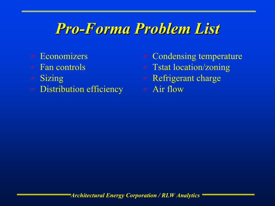
ProPro--Forma Problem ListForma Problem ListEconomizersFan controlsSizingDistribution efficiency
Condensing temperatureTstat location/zoningRefrigerant chargeAir flow
Architectural Energy Corporation / RLW Analytics
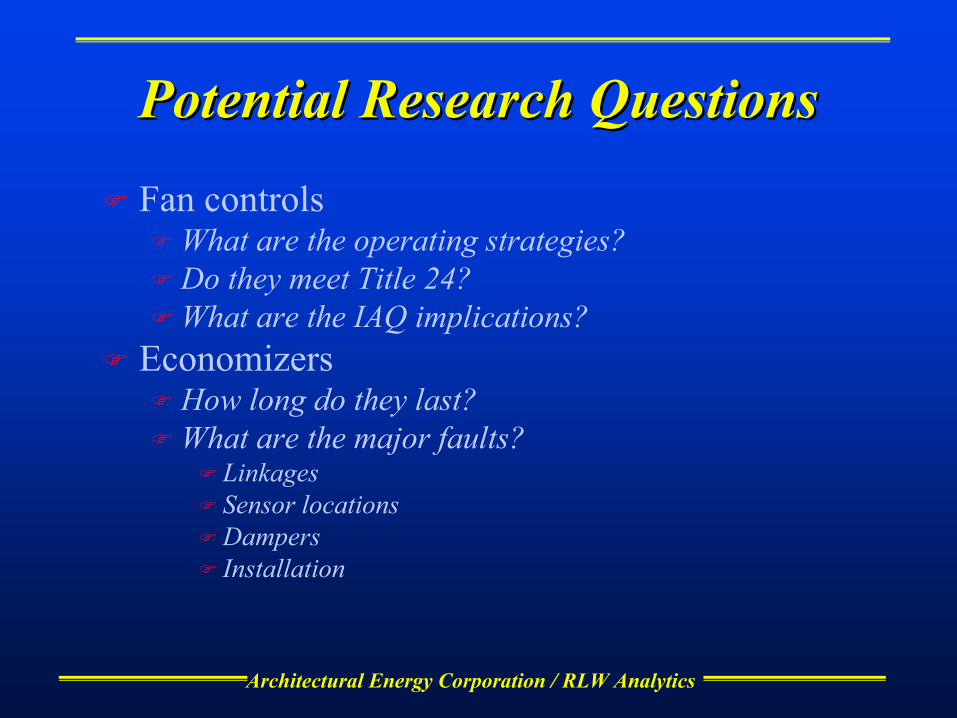
Potential Research QuestionsPotential Research Questions
Fan controlsWhat are the operating strategies?Do they meet Title 24?What are the IAQ implications?
EconomizersHow long do they last?What are the major faults?
LinkagesSensor locationsDampersInstallation
Architectural Energy Corporation / RLW Analytics
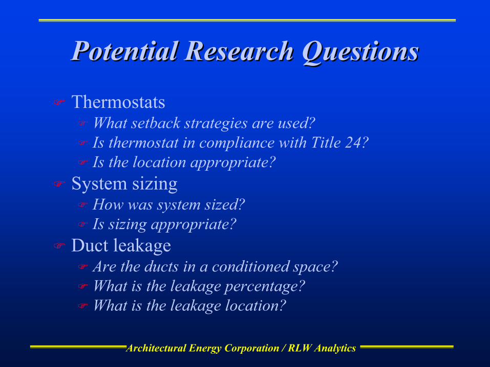
Potential Research QuestionsPotential Research Questions
ThermostatsWhat setback strategies are used?Is thermostat in compliance with Title 24?Is the location appropriate?
System sizingHow was system sized?Is sizing appropriate?
Duct leakageAre the ducts in a conditioned space?What is the leakage percentage?What is the leakage location?
Architectural Energy Corporation / RLW Analytics
Potential Research QuestionsPotential Research Questions
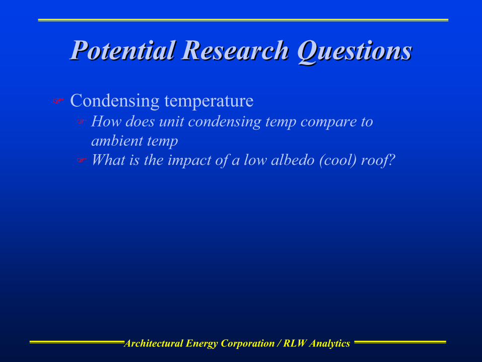
Condensing temperatureHow does unit condensing temp compare to ambient tempWhat is the impact of a low albedo (cool) roof?

Architectural Energy Corporation / RLW Analytics
Program tasksProgram tasks
Project Planning and ManagementMarket AdvisorsBackground ResearchField SurveysAnalysisBuilding Science SolutionsDesign GuidelinesFinal Report

Architectural Energy Corporation / RLW Analytics
Market AdvisorsMarket Advisors
Form technical advisors group (TAG)Assist research planningReview results during implementation phaseHelp define research products
Evaluate market responseinterviewsfocus groups case studiesdemonstrations
Identify remaining non-technical market barriers
Architectural Energy Corporation / RLW Analytics
Background ResearchBackground Research
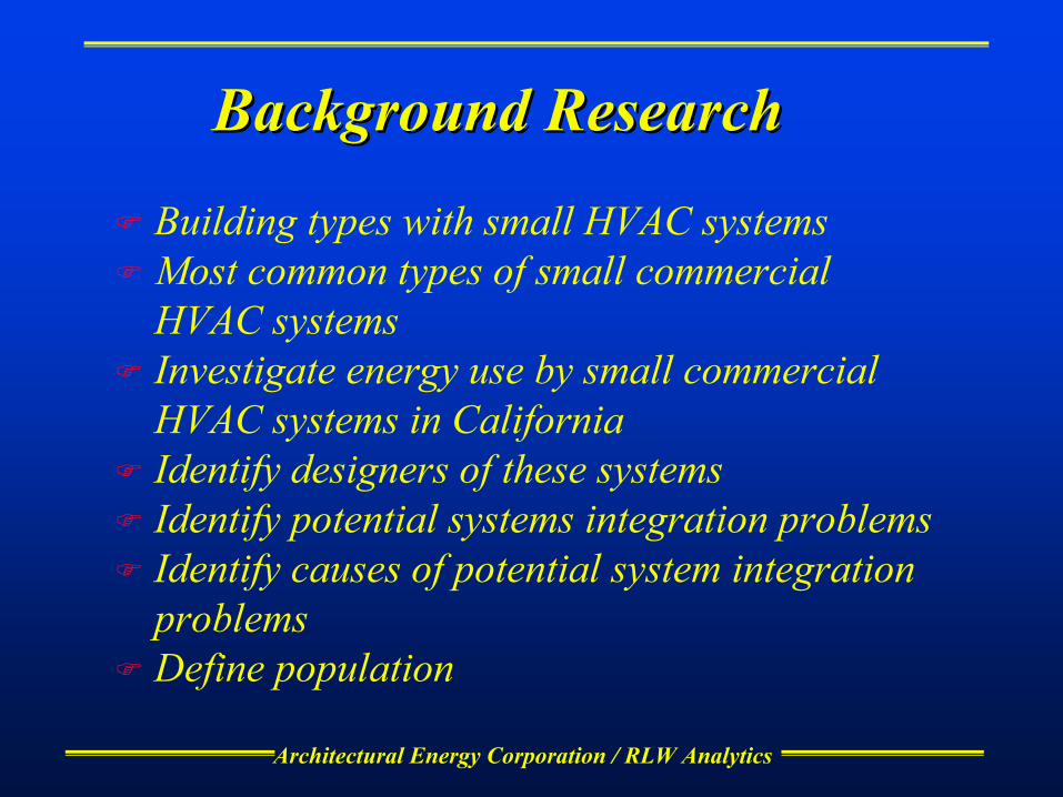
Building types with small HVAC systemsMost common types of small commercial HVAC systemsInvestigate energy use by small commercial HVAC systems in CaliforniaIdentify designers of these systemsIdentify potential systems integration problemsIdentify causes of potential system integration problemsDefine population
Architectural Energy Corporation / RLW Analytics
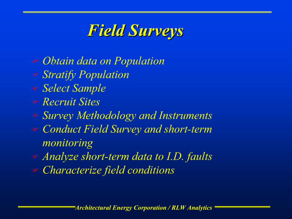
Field SurveysField Surveys
Obtain data on PopulationStratify PopulationSelect SampleRecruit SitesSurvey Methodology and InstrumentsConduct Field Survey and short-term monitoringAnalyze short-term data to I.D. faultsCharacterize field conditions

Architectural Energy Corporation / RLW Analytics
AnalysisAnalysis
Investigate the factors contributing to failure or sub-optimum performanceDevelop computer models for each surveyed buildingCalibrate the models with utility and/or short-term measured dataUse the model to analyze faults and determine lost savings Expand Data to Population
Architectural Energy Corporation / RLW Analytics
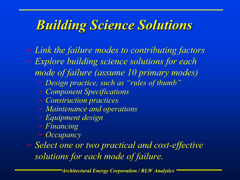
Building Science SolutionsBuilding Science Solutions
Link the failure modes to contributing factors Explore building science solutions for each mode of failure (assume 10 primary modes)
Design practice, such as “rules of thumb”Component SpecificationsConstruction practicesMaintenance and operationsEquipment designFinancingOccupancy
Select one or two practical and cost-effective solutions for each mode of failure.

Architectural Energy Corporation / RLW Analytics
Design GuidelinesDesign Guidelines
Specify target audiences for market transformation activities Develop design guidelines to address each failure mode Propose design guidelines for system design, construction, integration, commissioning, maintenance and operationsPropose improvements to codes and standards

Architectural Energy Corporation / RLW Analytics
ScheduleScheduleProject/
Task Number Task Name D
eliv
erab
le
Num
ber
Deliverable(s)Accel.*
Start Date
Accel.* Completion
Date
4.1Project Planning and Management
4.1.1 Program Kickoff Meeting 4.1.1 • Meeting notes and summary TBA 19-Jul-004.1.2 Project Review Meetings with CEC 4.1.2 • Meeting notes and summary Periodic
4.2.1 • Suggested list of TAG members in year 1 2-Apr-01 15-May-014.2.2 • Form TAG in year 2 (accelerate to year 1) 2-Apr-01 1-Jun-014.2.3 • Report on initial meeting· 1-Jul-01 1-Aug-014.2.4 • Meetings minutes and summary 1-Aug-01 1-Aug-03
4.3.1 • Summary of background research results 1-Apr-01 1-Aug-014.3.2 • List of system integration research issues to be addressed 1-May-01 1-Aug-01
4.4.1 • Description of the field methods. 1-May-01 1-Aug-014.4.2 • Survey method and questionnaires 1-Jun-01 1-Aug-014.4.3 • Database of compiled information from the field surveys. 1-Jul-01 1-Feb-02
4.5.1• Report on underlying causes of faults or sub-optimum performance in each building. 1-Nov-01 1-Jun-02
4.5.2 • Results from computer models for each building. 1-Nov-01 1-Jun-024.5.3 • Results from expanding the faults to the statewide population of buildings. 1-Jun-02 1-Sep-02
4.6.1 • Report describing the problems and their building science solutions 1-Mar-02 1-Dec-02
4.7.1 • Draft Design Guidelines for approval. 1-Jun-02 1-Sep-024.7.2 • Proposed Design guidelines for specific organizations 1-Jun-02 1-Dec-024.7.3 • Draft proposed improvements to codes and standards for approval 1-Jun-02 1-Dec-024.7.4 • Draft Final Design Guidelines for approval 1-Sep-02 1-Dec-024.7.5 • Final Design Guidelines 1-Dec-02 1-Feb-034.7.6 • Final Proposed improvements to codes and standards for approval 1-Dec-02 1-Feb-034.7.7 • Final Proposed improvements to codes and standards 1-Dec-02 1-Feb-03
4.6 Building Science Solutions
4.7
Design and Integration Solutions
4.4
Field Surveys
4.5
Analysis and Statewide Estimates
4.2
Technical and Market Advisors
4.3Background Research

Architectural Energy Corporation / RLW Analytics
Background ResearchBackground Research
Architectural Energy Corporation / RLW Analytics
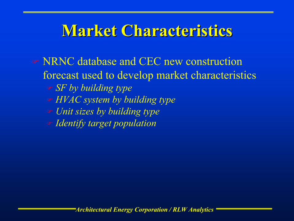
Market CharacteristicsMarket Characteristics
NRNC database and CEC new construction forecast used to develop market characteristics
SF by building typeHVAC system by building typeUnit sizes by building typeIdentify target population
Architectural Energy Corporation / RLW Analytics
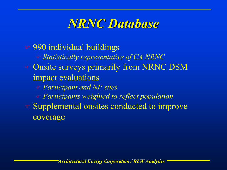
NRNC DatabaseNRNC Database
990 individual buildingsStatistically representative of CA NRNC
Onsite surveys primarily from NRNC DSM impact evaluations
Participant and NP sitesParticipants weighted to reflect population
Supplemental onsites conducted to improve coverage

Architectural Energy Corporation / RLW Analytics
Linkage to DOELinkage to DOE--22
Automated modeling software linked to databaseCreates DOE-2 models from building characteristicsAutomated parametric analysisSet up for batch processing

Architectural Energy Corporation / RLW Analytics
NRNC Database and CEC NRNC Database and CEC ProjectionsProjections
Share of Total NRNC Market
0
0.05
0.1
0.15
0.2
0.25
0.3
Office
Restaurants
Retail
Food Stores
Non-Refrg Whses
Refrg Whse
Elem/Scndry SchoolsColleges, UniversitiesHospitals
Hotel/Motel
Misc.
Building Type
Mar
ket S
hare
(% o
f tot
al S
F)
CEC ProjectionsNRNC Database
Architectural Energy Corporation / RLW Analytics
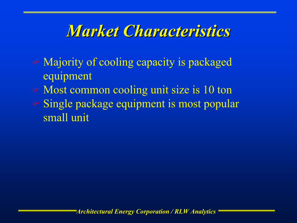
Market CharacteristicsMarket Characteristics
Majority of cooling capacity is packaged equipmentMost common cooling unit size is 10 tonSingle package equipment is most popular small unit

Architectural Energy Corporation / RLW Analytics
Unit Type DistributionUnit Type Distribution
Installed Capacity Distribution of Packaged Equipment
Single Package Rooftop AC78%
Single Package Rooftop Heat Pump
10%
Split System AC10%
Split System Heat Pump2%

Architectural Energy Corporation / RLW Analytics
Market CharacteristicsMarket Characteristics
Cooling System Type Distribution by Floorspace
No Cooling19.4%
Single Pkg DX AC43.9%
Single Pkg DX Heat Pump3.5%
Split DX AC5.9%
Split DX Heat Pump0.9%
Water Loop Heat Pump2.9%
Evaporative System5.7%
Built-up System17.4%
Other0.3%

Architectural Energy Corporation / RLW Analytics
Market CharacteristicsMarket Characteristics
System Type Distribution by Number of Systems
Single Package Rooftop AC69%
Single Package Rooftop Heat Pump12%
Split System AC14%
Split System Heat Pump5%
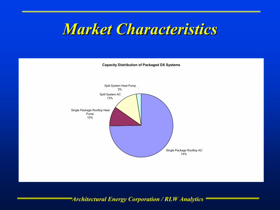
Architectural Energy Corporation / RLW Analytics
Market CharacteristicsMarket Characteristics
Capacity Distribution of Packaged DX Systems
Single Package Rooftop AC74%
Single Package Rooftop Heat Pump10%
Split System AC13%
Split System Heat Pump3%

Architectural Energy Corporation / RLW Analytics
Market CharacteristicsMarket CharacteristicsHVAC Unit Size Distribution by Quantity
0%
5%
10%
15%
20%
25%
30%
1 2 3 4 5 6 7 10 12 15 20 25 30 40 50 75 100
Unit size (ton)
Estim
ated
NR
NC
Uni
tary
Sys
tem
Mar
ket S
hare
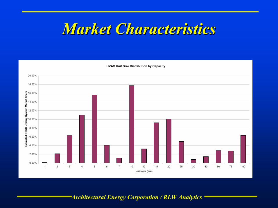
Architectural Energy Corporation / RLW Analytics
Market CharacteristicsMarket Characteristics
HVAC Unit Size Distribution by Capacity
0.00%
2.00%
4.00%
6.00%
8.00%
10.00%
12.00%
14.00%
16.00%
18.00%
20.00%
1 2 3 4 5 6 7 10 12 15 20 25 30 40 50 75 100
Unit size (ton)
Estim
ated
NR
NC
Uni
tary
Sys
tem
Mar
ket S
hare

Architectural Energy Corporation / RLW Analytics
Market Characteristics Market Characteristics Cumulative Capacity by Unit Size
0%
10%
20%
30%
40%
50%
60%
70%
80%
90%
100%
1 2 3 4 5 6 7 10 12 15 20 25 30 40 50 75 100
Unit Size
Perc
ent T
otal
Cap
acity

Architectural Energy Corporation / RLW Analytics
Relevant ResearchRelevant Research
CommercialLBNL Duct leakage in small commercial buildings (Delp, et al.)PG&E Economizer study (Feltz)AEC in-house building diagnostics projectsNEES Commercial RTU Tune-upCurrent Modera study for SCECEE Commercial Guidelines
ResidentialDuct leakage (Modera, Proctor)Refrigerant charge (Proctor, Neal)Air flow(Proctor, Neal, FSEC)
Architectural Energy Corporation / RLW Analytics
Field ActivitiesField Activities
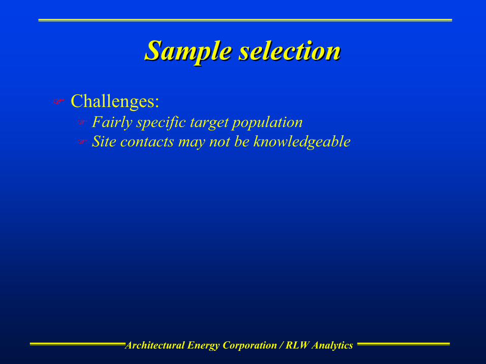
Architectural Energy Corporation / RLW Analytics
Sample selectionSample selection
Challenges:Fairly specific target populationSite contacts may not be knowledgeable
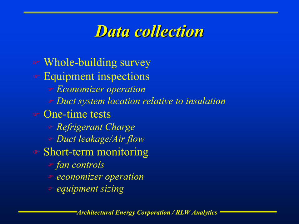
Architectural Energy Corporation / RLW Analytics
Data collectionData collection
Whole-building surveyEquipment inspections
Economizer operationDuct system location relative to insulation
One-time testsRefrigerant ChargeDuct leakage/Air flow
Short-term monitoringfan controlseconomizer operationequipment sizing

Architectural Energy Corporation / RLW Analytics
Sample DesignSample Design
82 total sitesAll sites:
On-site surveyEquipment inspectionsShort term monitoring
SubsampleRefrigerant chargeAir flow and duct leakage
Make best use of resources for surveys, testing and modeling to answer questions
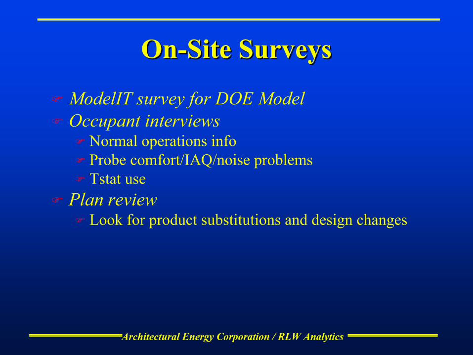
Architectural Energy Corporation / RLW Analytics
OnOn--Site SurveysSite Surveys
ModelIT survey for DOE ModelOccupant interviews
Normal operations infoProbe comfort/IAQ/noise problemsTstat use
Plan reviewLook for product substitutions and design changes
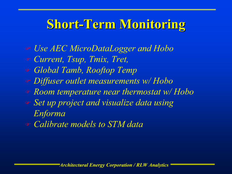
Architectural Energy Corporation / RLW Analytics
ShortShort--Term MonitoringTerm Monitoring
Use AEC MicroDataLogger and HoboCurrent, Tsup, Tmix, Tret, Global Tamb, Rooftop TempDiffuser outlet measurements w/ HoboRoom temperature near thermostat w/ HoboSet up project and visualize data using EnformaCalibrate models to STM data

Architectural Energy Corporation / RLW Analytics
Economizer TestingEconomizer Testing
Observations:Minimum OA setpointController setpointPhysical condition
Functional Testoverride controller to observe open/close cyclesimulate cool conditions; observe response
Plot STM dataTmix, Tamb, Tret

Architectural Energy Corporation / RLW Analytics
Refrigerant Charge TestingRefrigerant Charge Testing
Will sub out to CheckMe contractorsUses pressure and temperature measurementsCan flag for high/low airflowTest a sub-sample of units
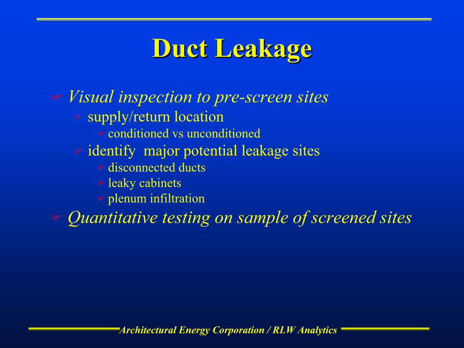
Architectural Energy Corporation / RLW Analytics
Duct LeakageDuct Leakage
Visual inspection to pre-screen sitessupply/return location
conditioned vs unconditioned identify major potential leakage sites
disconnected ductsleaky cabinetsplenum infiltration
Quantitative testing on sample of screened sites

Architectural Energy Corporation / RLW Analytics
Analysis and Impact EstimatesAnalysis and Impact Estimates
Impacts will be modeled and projected to population using NRNC database
DOE-2 modeling software programmed to simulate impact of faults
DOE-2 models of all sites in NRNC database to project impacts to all buildings
Field data used to estimate fraction of sites with problems
Calculate energy consumption, demand, cost, and ventilation impacts
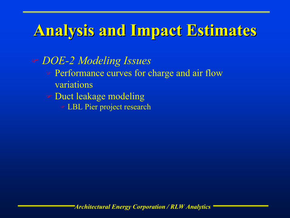
Architectural Energy Corporation / RLW Analytics
Analysis and Impact EstimatesAnalysis and Impact Estimates
DOE-2 Modeling IssuesPerformance curves for charge and air flow variationsDuct leakage modeling
LBL Pier project research
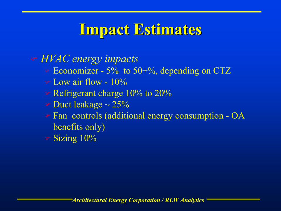
Architectural Energy Corporation / RLW Analytics
Impact EstimatesImpact Estimates
HVAC energy impactsEconomizer - 5% to 50+%, depending on CTZLow air flow - 10%Refrigerant charge 10% to 20%Duct leakage ~ 25%Fan controls (additional energy consumption - OA benefits only)Sizing 10%
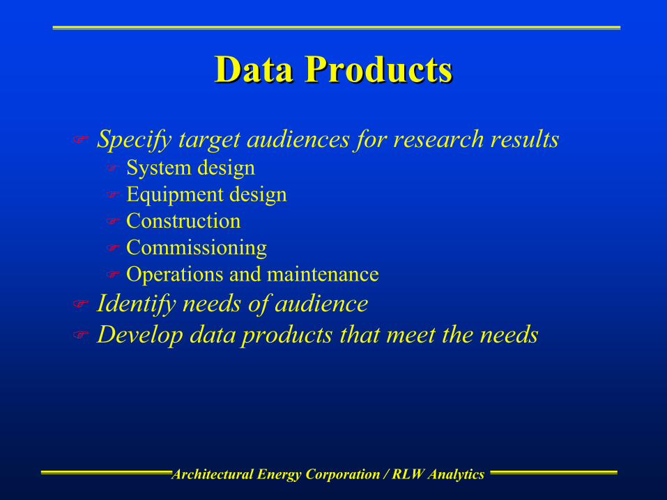
Architectural Energy Corporation / RLW Analytics
Data ProductsData Products
Specify target audiences for research resultsSystem designEquipment designConstructionCommissioningOperations and maintenance
Identify needs of audienceDevelop data products that meet the needs
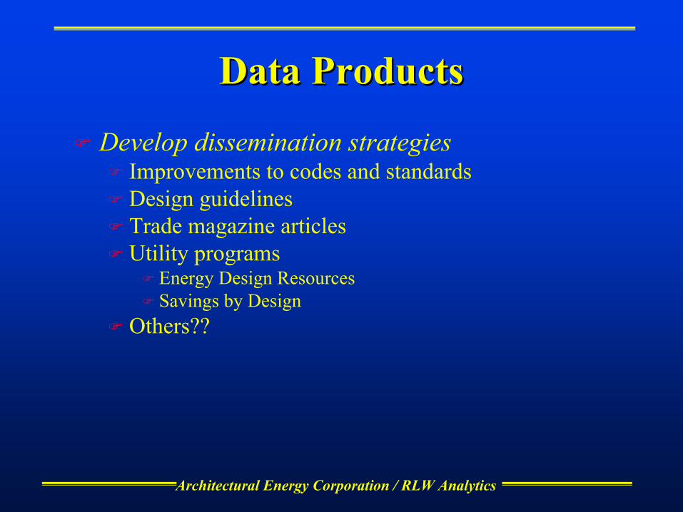
Architectural Energy Corporation / RLW Analytics
Data ProductsData Products
Develop dissemination strategiesImprovements to codes and standardsDesign guidelinesTrade magazine articlesUtility programs
Energy Design ResourcesSavings by Design
Others??
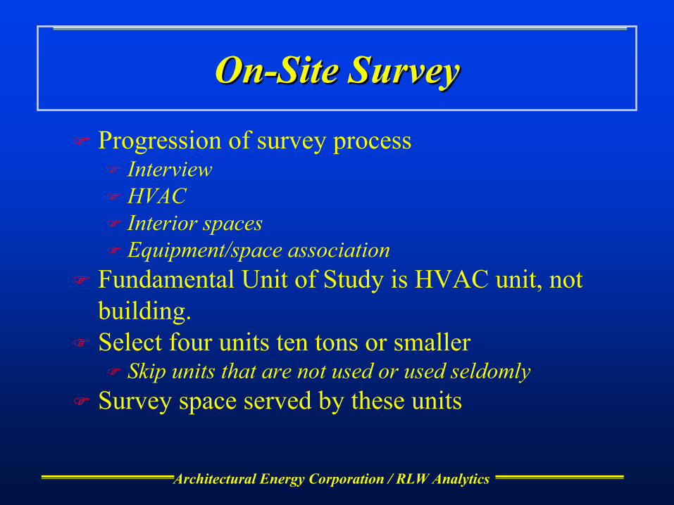
Architectural Energy Corporation / RLW Analytics
OnOn--Site SurveySite Survey
Progression of survey processInterviewHVACInterior spacesEquipment/space association
Fundamental Unit of Study is HVAC unit, not building.Select four units ten tons or smaller
Skip units that are not used or used seldomlySurvey space served by these units

Architectural Energy Corporation / RLW Analytics
OnOn--Site SurveySite Survey
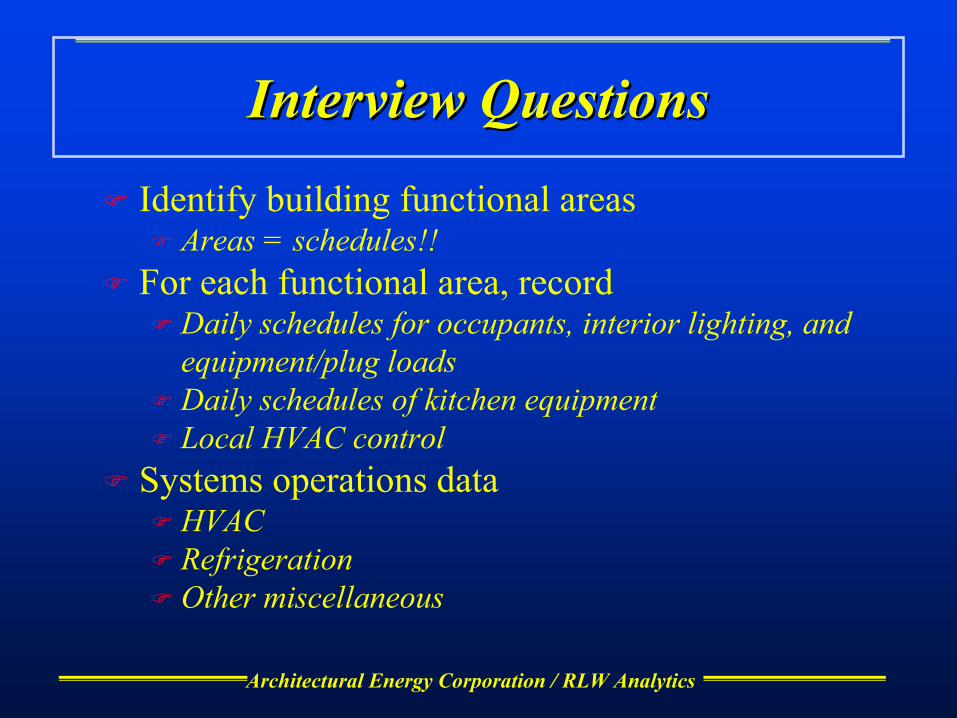
Architectural Energy Corporation / RLW Analytics
Interview QuestionsInterview Questions
Identify building functional areasAreas = schedules!!
For each functional area, recordDaily schedules for occupants, interior lighting, and equipment/plug loadsDaily schedules of kitchen equipmentLocal HVAC control
Systems operations dataHVACRefrigerationOther miscellaneous
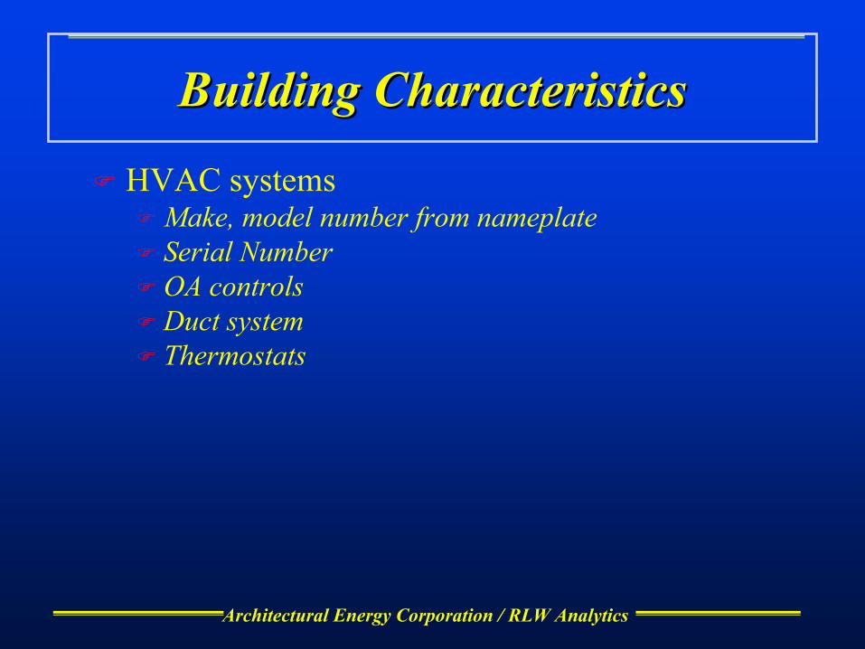
Architectural Energy Corporation / RLW Analytics
Building CharacteristicsBuilding Characteristics
HVAC systemsMake, model number from nameplateSerial NumberOA controlsDuct systemThermostats
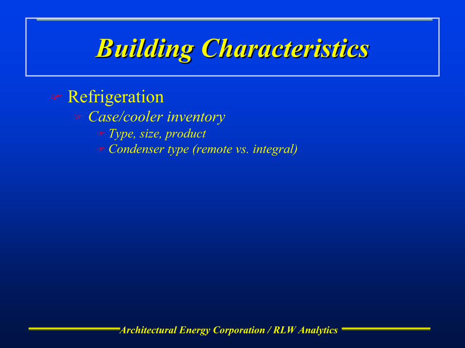
Architectural Energy Corporation / RLW Analytics
Building CharacteristicsBuilding Characteristics
RefrigerationCase/cooler inventory
Type, size, product Condenser type (remote vs. integral)

Architectural Energy Corporation / RLW Analytics
Building CharacteristicsBuilding Characteristics
Cooking equipmentCookline inventory
Type, size, fuel typeHood inventory
Type, size, appliances served, fan power
Architectural Energy Corporation / RLW Analytics
Building CharacteristicsBuilding Characteristics
Interior spacesOccupancyLightingPlug and process loads
ShellWall type, R-value, orientationWindow type, shading, orientation
Architectural Energy Corporation / RLW Analytics
Component RelationshipsComponent Relationships
Associate areas and spacesAssociate HVAC equipment and spacesEstablish zoningFour zones, Four systems, One Unit/system
Architectural Energy Corporation / RLW Analytics
Areas, Spaces, Zones and SystemsAreas, Spaces, Zones and Systems
Area refers to schedulesSpace refers to interior floor space or rooms
Defined by occupancyZone is a collection of spaces served by a system
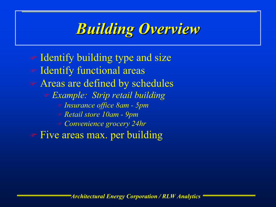
Architectural Energy Corporation / RLW Analytics
Building OverviewBuilding Overview
Identify building type and sizeIdentify functional areasAreas are defined by schedules
Example: Strip retail buildingInsurance office 8am - 5pmRetail store 10am - 9pmConvenience grocery 24hr
Five areas max. per building

Architectural Energy Corporation / RLW Analytics
SchedulesSchedules
A separate set of schedules is defined for each functional areaMake duplicate pages - fill-out one set for each areaDaytypes
Full operation (normal workday)Light operation (partial workday)ClosedAssign to days of week
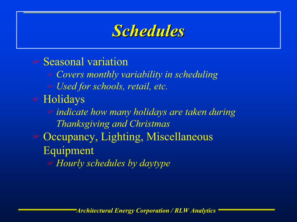
Architectural Energy Corporation / RLW Analytics
SchedulesSchedules
Seasonal variationCovers monthly variability in schedulingUsed for schools, retail, etc.
Holidaysindicate how many holidays are taken during Thanksgiving and Christmas
Occupancy, Lighting, Miscellaneous Equipment
Hourly schedules by daytype

Architectural Energy Corporation / RLW Analytics
SchedulesSchedules
Graphical input - interpret to nearest 10 percent
0
20
40
60
80
10
1 2 3 4 5 6 7 8 9 10 11 12 13 14 15 16 17 18 19 20 21 22 23 24
Hour

Architectural Energy Corporation / RLW Analytics
SchedulesSchedules
Kitchen - discrete operating levels

Architectural Energy Corporation / RLW Analytics
SchedulesSchedules
Fan system
on
off
1 2 3 4 5 6 7 8 9 10 11 12 13 14 15 16 17 18 19 20 21 22 23 24

Architectural Energy Corporation / RLW Analytics
SchedulesSchedules
Thermostat
Unocc CSP
Occ CSP
Occ HSP
Unocc HSP
1 2 3 4 5 6 7 8 9 10 11 12 13 14 15 16 17 18 19 20 21 22 23 24

Architectural Energy Corporation / RLW Analytics
Packaged HVACPackaged HVAC
System typesSingle package AC and heat pumpSplit system AC and heat pump
Not in scope:PTAC/PTHPWindow/wall unitsWater loop heat pumpsEvaporative systems
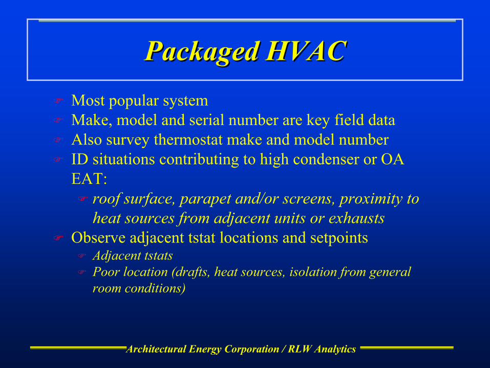
Architectural Energy Corporation / RLW Analytics
Packaged HVACPackaged HVACMost popular systemMake, model and serial number are key field dataAlso survey thermostat make and model numberID situations contributing to high condenser or OA EAT:
roof surface, parapet and/or screens, proximity to heat sources from adjacent units or exhausts
Observe adjacent tstat locations and setpointsAdjacent tstatsPoor location (drafts, heat sources, isolation from general room conditions)
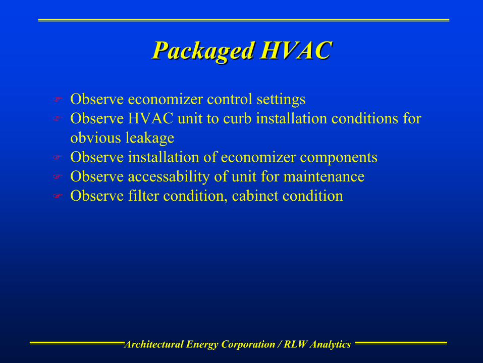
Architectural Energy Corporation / RLW Analytics
Packaged HVACPackaged HVAC
Observe economizer control settingsObserve HVAC unit to curb installation conditions for obvious leakageObserve installation of economizer componentsObserve accessability of unit for maintenanceObserve filter condition, cabinet condition
Architectural Energy Corporation / RLW Analytics
Duct LossesDuct Losses
LocationPlenumConditionedOutsideOther (notes)

Architectural Energy Corporation / RLW Analytics
Duct LossesDuct Losses
ConstructionSheet metalFlexFiberglassDuctboardOther
R-valuearea

Architectural Energy Corporation / RLW Analytics
Plenum Plenum
Under “Roof” TabRoof U- or R-valueCeiling R-valuePlenum wall R-valuePlenum height
Use average height for plenum wall lossesIndicate if return plenum
Architectural Energy Corporation / RLW Analytics
Exterior SurfacesExterior Surfaces
Need U-value and HC for each opaque surface enclosing the zone
Observe from plans or Title 24 ENV formCalculated from wall type and R-value
Try to look at plans - tough to observe insulation R-values in the fieldEstimate gross height and width, and orientation of each surface enclosing the zone
Check floor plans and elevations, bring an architects scaleUse a tape measure if necessaryHeight and width are gross, including windows

Architectural Energy Corporation / RLW Analytics
WindowsWindows
Need U-value and shading coefficient (SC)Observe from Title 24 ENV form or plansMeasure glazing transmission
Estimate height and width and orientation of each window enclosing the zone
Check floor plans and elevations, bring an architects scaleUse a tape measure if necessary
Observe interior and exterior shadingOverhangs
Offset is distance from top of window to bottom of overhangProjection is distance from wall to edge of overhang

Architectural Energy Corporation / RLW Analytics
Cool RoofsCool Roofs
Roof color for cooling savingsRoof “aged” reflectance (Cool Roof Rating Council)Roof color (reflectance defaulted)
Survey material type and color
Architectural Energy Corporation / RLW Analytics
SpaceSpaceSpace is the smallest unit of floor area surveyedSometimes zones are too big to be surveyed efficientlyObserve occupancy correctly - very important!!Estimate floor area, % corridor, restroom or support areaIdentify and count lighting fixtures and controlsSurvey plug loadsSpace multiplier can save time
Architectural Energy Corporation / RLW Analytics
LightingLighting
Observe fixture type(s), enter a fixture code for each type observed in the spaceCount the fixtures - very important to get an accurate count!Identify lighting controls, and % of fixtures controlled

Architectural Energy Corporation / RLW Analytics
Miscellaneous Equipment and Plug Miscellaneous Equipment and Plug LoadsLoads
Try to get a good count, since surveyed area is smallHVAC sizing is a key issue
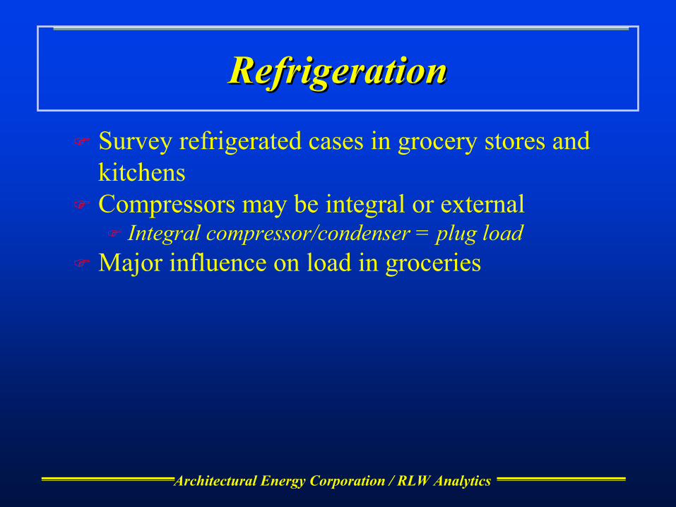
Architectural Energy Corporation / RLW Analytics
RefrigerationRefrigeration
Survey refrigerated cases in grocery stores and kitchensCompressors may be integral or external
Integral compressor/condenser = plug loadMajor influence on load in groceries

Architectural Energy Corporation / RLW Analytics
Refrigerated CasesRefrigerated Cases
Survey by case type and product displayedProduct code determines temperature
Units of measure vary by case typeWalk-in/reach-in -survey floor area and number of doorsWalk-in - survey floor areaClosed cases - look a number of glazing panes
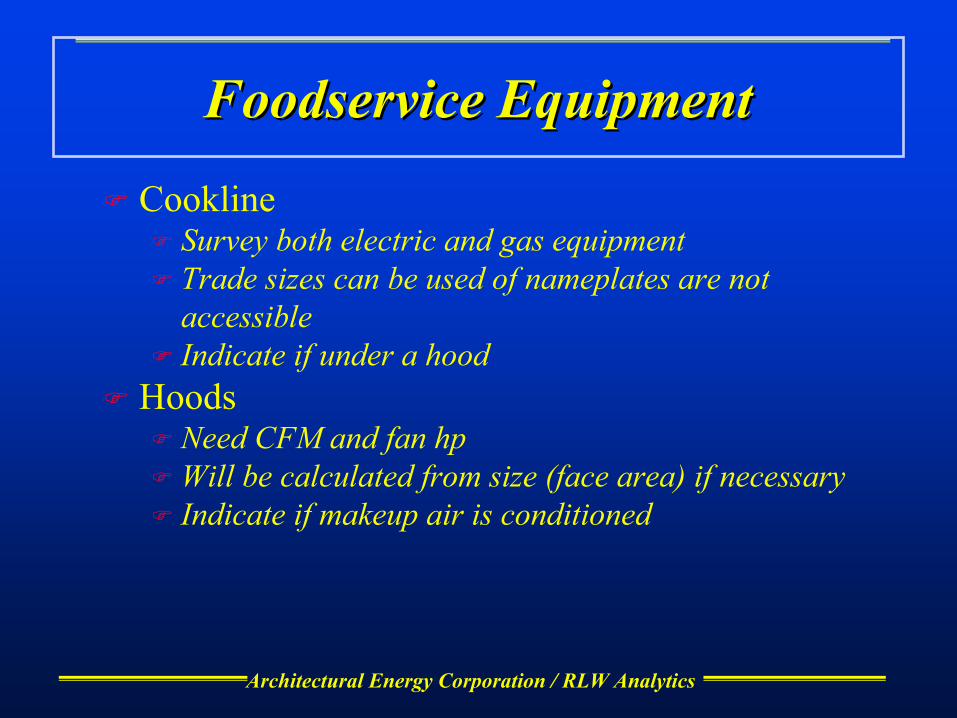
Architectural Energy Corporation / RLW Analytics
Foodservice EquipmentFoodservice Equipment
CooklineSurvey both electric and gas equipmentTrade sizes can be used of nameplates are not accessibleIndicate if under a hood
HoodsNeed CFM and fan hpWill be calculated from size (face area) if necessaryIndicate if makeup air is conditioned

Architectural Energy Corporation / RLW Analytics
Component RelationshipsComponent Relationships
ZoningUnusual internal gainsOperating schedulesFollow HVAC zoning
HVAC system/zone association checklistAssemble inventoried HVAC components into a systemAssign systems to zones served
Functional area/zone association checklistSpace/zone association checklist

Architectural Energy Corporation / RLW Analytics
System/Zone Association ChecklistSystem/Zone Association ChecklistVery important - builds the model from the various “pieces” surveyedSystems are DOE-2 “virtual” system; should be one unit/systemAll equipment and zones surveyed must be accounted forZone can’t be served by more than one system

Architectural Energy Corporation / RLW Analytics
Area/Zone and Space Association Area/Zone and Space Association ChecklistsChecklists
Area/Zone Association Attaches schedules (areas) to zonesOnly one area/zoneAll defined areas must be associated to a zone, and vice versa
Space/Zone AssociationAggregates spaces into zonesOnly one zone per spaceAll spaces and zones must be accounted for
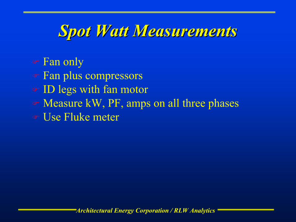
Architectural Energy Corporation / RLW Analytics
Spot Watt MeasurementsSpot Watt Measurements
Fan onlyFan plus compressorsID legs with fan motorMeasure kW, PF, amps on all three phasesUse Fluke meter

Architectural Energy Corporation / RLW Analytics
STM
Compare ambient temp, condenser or OA EAT to design tempID fan operating schedule, compare with building scheduleMeasure condenser or OA EAT. Set up ambient station to measure ambient temp and RHObserve economizer operation, look for faults

Architectural Energy Corporation / RLW Analytics
STMSTM
Observe HVAC system operation for evidence of oversizingReview time series plots of heating and cooling on adjacent units

Architectural Energy Corporation / RLW Analytics
Mfg Lit review
Check cooling capacityCheck economizer installation instructions for major componentsCompare factory recommendations to Title 24 requirementsGet manufacturer recommendations on installation proceduresIdentify unit mounting and curb sealing requirements

Architectural Energy Corporation / RLW Analytics
Mfg Lit review
Review installation instructionsReview thermostat fan control capabilities
See if economizer is available as a factory option
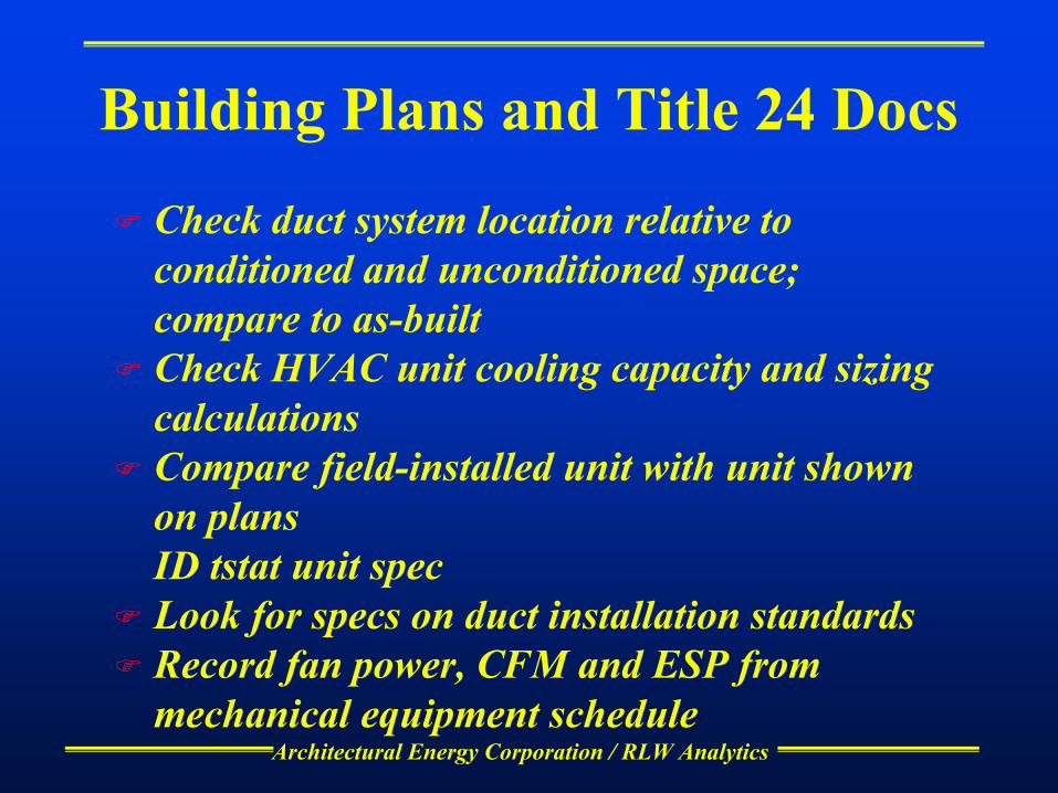
Architectural Energy Corporation / RLW Analytics
Building Plans and Title 24 Docs
Check duct system location relative to conditioned and unconditioned space; compare to as-builtCheck HVAC unit cooling capacity and sizing calculationsCompare field-installed unit with unit shown on plansID tstat unit specLook for specs on duct installation standardsRecord fan power, CFM and ESP from mechanical equipment schedule

NBI / AEC PIER Element 4 Small HVAC Onsite Survey Form (Ver. 6) ID:
Page 1
General Information
Site ID #
Surveyor Name: Building Name:
Date: Primary Contact: Phone:
Building Address:
City Zip
Start Time: Finish Time:
Interview Questions The following interview questions will be used to help us identify unobservable aspects of your building. These aspects include occupancy history, schedules, and heating and cooling controls. Answers to these questions will be coupled with data collected from our walk-through audit to produce a computer model which simulates the annual energy use of the building. Building Overview Q1. What is the overall floor area affected by the new construction/remodeling/renovation at the site? ___________________________. Compare this value to the square footage value located on the “On-Site Form”. Please comment on any discrepancies below. _______________________________________________________________________________________________________________________________________________________________________________________________________________________________________________________________________________________________________________________________________________ Q2. What is the floor area served by small HVAC units?
❏ same as overall building floor area ❏ ____________SF
Q3. How many floors? ___________ Q4. Characterize the site by circling the appropriate description: 1. New building (“green field”) 2. Alteration of existing building 3. Addition to existing building 4. Alteration of existing building and addition to existing building

NBI / AEC PIER Element 4 Small HVAC Onsite Survey Form (Ver. 6) ID:
Page 2
Q5. Circle the appropriate building type description:
1 Large office 11 Hospital 2 Small office 12 Medical Clinic 3 Restaurants 13 Hotel/Motel 4 Large retail 14 Miscellaneous 5 Small Retail 6 Food Stores 7 Refrigerated Warehouse 8 Non-Refrigerated Warehouse 9 Elementry / Secondary School 10 College / University

NBI / AEC PIER Element 4 Small HVAC Onsite Survey Form (Ver. 6) ID:
Page 3
Building Areas Q6. Which statement best describes the operation of the building? ( ) The entire building operates on basically the same schedule
( ) There are areas of the building (departments, tenants, etc.) that have substantially different operating schedules
Q7. If different areas of the building (departments, tenants, etc.) have substantially different operational schedules, divide the building into up to five areas with differing schedules, and provide a name for each area:
1. ______________________
2. ______________________
3. ______________________
4. ______________________
5. ______________________
Notes:
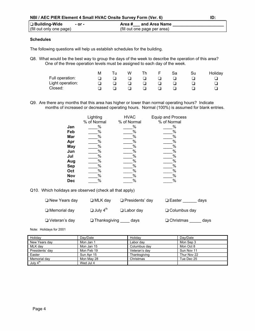
NBI / AEC PIER Element 4 Small HVAC Onsite Survey Form (Ver. 6) ID:
Page 4
❏ Building-Wide - or - Area #___ and Area Name ______________________ (fill out only one page) (fill out one page per area) Schedules The following questions will help us establish schedules for the building. Q8. What would be the best way to group the days of the week to describe the operation of this area?
One of the three operation levels must be assigned to each day of the week.
M Tu W Th F Sa Su Holiday Full operation: ❏ ❏ ❏ ❏ ❏ ❏ ❏ ❏ Light operation: ❏ ❏ ❏ ❏ ❏ ❏ ❏ ❏ Closed: ❏ ❏ ❏ ❏ ❏ ❏ ❏ ❏
Q9. Are there any months that this area has higher or lower than normal operating hours? Indicate
months of increased or decreased operating hours. Normal (100%) is assumed for blank entries.
Lighting HVAC Equip and Process % of Normal % of Normal % of Normal Jan ____% ____% ____% Feb ____% ____% ____% Mar ____% ____% ____% Apr ____% ____% ____% May ____% ____% ____% Jun ____% ____% ____% Jul ____% ____% ____% Aug ____% ____% ____% Sep ____% ____% ____% Oct ____% ____% ____% Nov ____% ____% ____% Dec ____% ____% ____%
Q10. Which holidays are observed (check all that apply) ❏ New Years day ❏ MLK day ❏ Presidents’ day ❏ Easter ______ days ❏ Memorial day ❏ July 4th ❏ Labor day ❏ Columbus day
❏ Veteran’s day ❏ Thanksgiving ____ days ❏ Christmas _____ days
Note: Holidays for 2001 Holiday Day/Date Holiday Day/Date New Years day Mon Jan 1 Labor day Mon Sep 3 MLK day Mon Jan 15 Columbus day Mon Oct 8 Presidents’ day Mon Feb 19 Veteran’s day Sun Nov 11 Easter Sun Apr 15 Thanksgiving Thur Nov 22 Memorial day Mon May 28 Christmas Tue Dec 25 July 4th Wed Jul 4
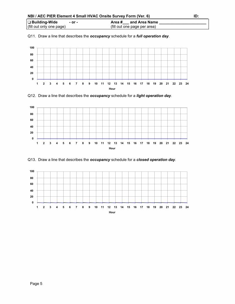
NBI / AEC PIER Element 4 Small HVAC Onsite Survey Form (Ver. 6) ID:
Page 5
❏ Building-Wide - or - Area #___ and Area Name ______________________ (fill out only one page) (fill out one page per area) Q11. Draw a line that describes the occupancy schedule for a full operation day.
0
20
40
60
80
100
1 2 3 4 5 6 7 8 9 10 11 12 13 14 15 16 17 18 19 20 21 22 23 24
Hour
Q12. Draw a line that describes the occupancy schedule for a light operation day.
0
20
40
60
80
100
1 2 3 4 5 6 7 8 9 10 11 12 13 14 15 16 17 18 19 20 21 22 23 24
Hour
Q13. Draw a line that describes the occupancy schedule for a closed operation day.
0
20
40
60
80
100
1 2 3 4 5 6 7 8 9 10 11 12 13 14 15 16 17 18 19 20 21 22 23 24
Hour

NBI / AEC PIER Element 4 Small HVAC Onsite Survey Form (Ver. 6) ID:
Page 6
❏ Building-Wide - or - Area #___ and Area Name ______________________ (fill out only one page) (fill out one page per area) Q14. Draw a line that describes the schedule of use for interior lighting for a full operation day.
0
20
40
60
80
100
1 2 3 4 5 6 7 8 9 10 11 12 13 14 15 16 17 18 19 20 21 22 23 24
Hour
Q15. Draw a line that describes the schedule of use for interior lighting for a light operation day.
0
20
40
60
80
100
1 2 3 4 5 6 7 8 9 10 11 12 13 14 15 16 17 18 19 20 21 22 23 24
Hour
Q16. Draw a line that describes the schedule of use for interior lighting for a closed operation day.
0
20
40
60
80
100
1 2 3 4 5 6 7 8 9 10 11 12 13 14 15 16 17 18 19 20 21 22 23 24
Hour
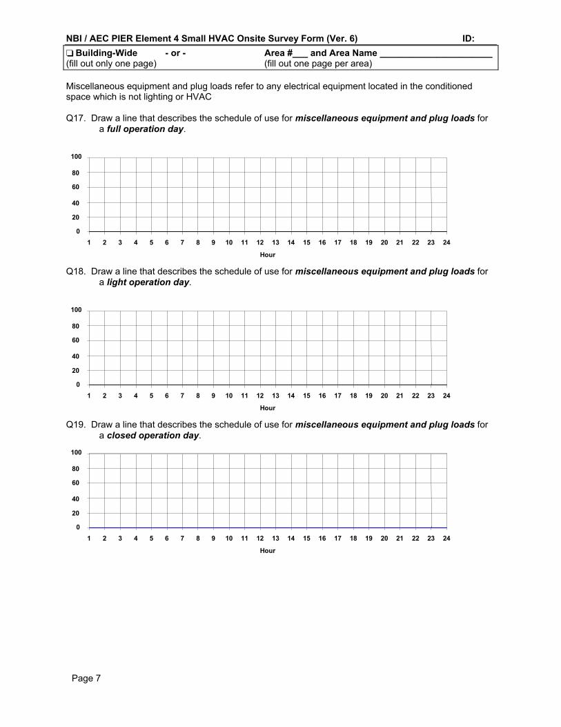
NBI / AEC PIER Element 4 Small HVAC Onsite Survey Form (Ver. 6) ID:
Page 7
❏ Building-Wide - or - Area #___ and Area Name ______________________ (fill out only one page) (fill out one page per area) Miscellaneous equipment and plug loads refer to any electrical equipment located in the conditioned space which is not lighting or HVAC Q17. Draw a line that describes the schedule of use for miscellaneous equipment and plug loads for
a full operation day.
0
20
40
60
80
100
1 2 3 4 5 6 7 8 9 10 11 12 13 14 15 16 17 18 19 20 21 22 23 24
Hour
Q18. Draw a line that describes the schedule of use for miscellaneous equipment and plug loads for a light operation day.
0
20
40
60
80
100
1 2 3 4 5 6 7 8 9 10 11 12 13 14 15 16 17 18 19 20 21 22 23 24
Hour
Q19. Draw a line that describes the schedule of use for miscellaneous equipment and plug loads for a closed operation day.
0
20
40
60
80
100
1 2 3 4 5 6 7 8 9 10 11 12 13 14 15 16 17 18 19 20 21 22 23 24
Hour
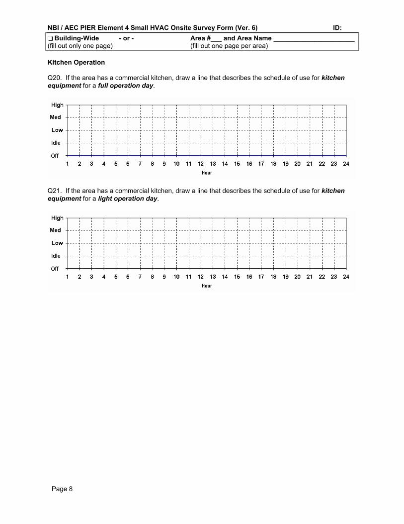
NBI / AEC PIER Element 4 Small HVAC Onsite Survey Form (Ver. 6) ID:
Page 8
❏ Building-Wide - or - Area #___ and Area Name ______________________ (fill out only one page) (fill out one page per area) Kitchen Operation Q20. If the area has a commercial kitchen, draw a line that describes the schedule of use for kitchen equipment for a full operation day.
Q21. If the area has a commercial kitchen, draw a line that describes the schedule of use for kitchen equipment for a light operation day.

NBI / AEC PIER Element 4 Small HVAC Onsite Survey Form (Ver. 6) ID:
Page 9
❏ Building-Wide - or - Area #___ and Area Name ______________________ (fill out only one page) (fill out one page per area) Room Thermostat Setpoints Q22. Enter the values for heating and cooling thermostat setpoints during normal (occupied) and setback
(unoccupied) periods
Period Heating Setpoint Cooling Setpoint
Occupied
Unoccupied
Set CSP to 99 for “off,” set the HSP to 45 for “off” Q23. Who is responsible for thermostat setpoint maintenance?
❏ Occupants ❏ Management ❏ HVAC service company
❏ Other (list) ______________
Q24. Are room temperatures in this area controlled by the building EMS? Y N DK
Q25. Does the setback schedule in this area follow the fan on/off schedule? Y N DK If the answer is N or DK, define the setback schedule below: Q26. Draw a line that defines the occupied and unoccupied mode for a full operation day. DK Occupied
Unoccupied
1 2 3 4 5 6 7 8 9 10 11 12 13 14 15 16 17 18 19 20 21 22 23 24
Q27. Draw a line that defines the occupied and unoccupied mode for a light operation day. DK Occupied
Unoccupied
1 2 3 4 5 6 7 8 9 10 11 12 13 14 15 16 17 18 19 20 21 22 23 24
Q28. Draw a line that defines the occupied and unoccupied mode for a closed operation day. DK Occupied
Unoccupied
1 2 3 4 5 6 7 8 9 10 11 12 13 14 15 16 17 18 19 20 21 22 23 24

NBI / AEC PIER Element 4 Small HVAC Onsite Survey Form (Ver. 6) ID:
Page 10
HVAC Fan System Operation This section is used to establish the fan system schedule. List the hours that the fans are “on” or “off.” “On” indicates occupied mode, where the fans run continuously. “Off” indicates unoccupied mode, where the fans cycle on only if needed to satisfy space temperature needs, or are shut off regardless of space temperature.. Q29. Draw a line that describes the fan system operation for a full operation day: DK
on
off
1 2 3 4 5 6 7 8 9 10 11 12 13 14 15 16 17 18 19 20 21 22 23 24
Q30. Draw a line that describes the fan system operation for a light operation day. DK
on
off
1 2 3 4 5 6 7 8 9 10 11 12 13 14 15 16 17 18 19 20 21 22 23 24
Q31. Draw a line that describes the fan system operation for a closed operation day. DK
on
off
1 2 3 4 5 6 7 8 9 10 11 12 13 14 15 16 17 18 19 20 21 22 23 24
Q32. Is the fan system described above controlled by the building EMS? Y N DK Q33. Is the fan system described above controlled using an optimum start algorithm? Y N DK Note: For fans with optimal start/stop, indicate the building occupancy schedule - e.g. the time when the
building needs to be at normal operating temperature. Q34. List the nighttime (off cycle) control strategy for the fan system described above:
❏ Stay off regardless of room temperature ❏ Cycle on if any room requires heating or cooling ❏ DK
List the selected packaged HVAC systems that run on this schedule below:
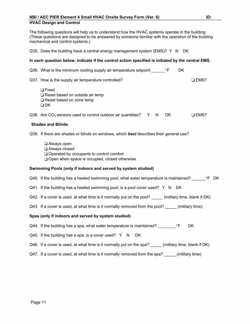
NBI / AEC PIER Element 4 Small HVAC Onsite Survey Form (Ver. 6) ID:
Page 11
HVAC Design and Control The following questions will help us to understand how the HVAC systems operate in the building. (These questions are designed to be answered by someone familiar with the operation of the building mechanical and control systems.) Q35. Does the building have a central energy management system (EMS)? Y N DK In each question below, indicate if the control action specified is initiated by the central EMS. Q36. What is the minimum cooling supply air temperature setpoint ______°F DK
Q37. How is the supply air temperature controlled? ❏ EMS?
❏ Fixed ❏ Reset based on outside air temp ❏ Reset based on zone temp ❏ DK
Q38. Are CO2 sensors used to control outdoor air quantities? Y N DK ❏ EMS? Shades and Blinds
Q39. If there are shades or blinds on windows, which best describes their general use? ❏ Always open ❏ Always closed ❏ Operated by occupants to control comfort ❏ Open when space is occupied, closed otherwise Swimming Pools (only if indoors and served by system studied) Q40. If the building has a heated swimming pool, what water temperature is maintained? ______°F DK Q41. If the building has a heated swimming pool, is a pool cover used? Y N DK Q42. If a cover is used, at what time is it normally put on the pool? _____ (military time, blank if DK) Q43. If a cover is used, at what time is it normally removed from the pool? _____ (military time) Spas (only if indoors and served by system studied) Q44. If the building has a spa, what water temperature is maintained? ________°F DK Q45. If the building has a spa, is a cover used? Y N DK Q46. If a cover is used, at what time is it normally put on the spa? _____ (military time, blank if DK) Q47. If a cover is used, at what time is it normally removed from the spa? _____ (military time)

NBI / AEC PIER Element 4 Small HVAC Onsite Survey Form (Ver. 6) ID:
Page 12 Attach additional pages as necessary Additional Page ❏ Page-b-c-d
Packaged HVAC Systems
AC- AC- AC- AC-
Equipment Name
Location
Manufacturer
Model No (outdoor)
Model No (indoor)
Serial Number
Cooling Cap (ton)
Cooling Efficiency EER
SEER EER
SEER EER
SEER EER
SEER
Heating Fuel Elec / Other Elec / Other Elec / Other Elec / Other
Heating Capacity (kBtuh))
Heating Efficiency) COP
HSPF AFUE
COP HSPF AFUE
COP HSPF AFUE
COP HSPF AFUE
Supply CFM
Supply fan hp
Sup fan mtr effic
Sup fan control Const / Cycles ❏ EMS Const / Cycles ❏ EMS Const / Cycles ❏ EMS Const / Cycles ❏ EMS
Ret/Rel fan hp
Rel fan mtr effic
OA Control Fix/Tmp/Enth ❏ EMS Fix/Tmp/Enth ❏ EMS Fix/Tmp/Enth ❏ EMS Fix/Tmp/Enth ❏ EMS
Min OA Fraction
Tstat Make/Mod
Tstat Location Note: heating capacity for heat pumps is for compressor only; circle COP or HSPF for heat pumps, AFUE for gas heat Note variance from plans and as-built; rooftop heat sources, curb leakage, accessibility, unusual tstat mounting or location.

NBI / AEC PIER Element 4 Small HVAC Onsite Survey Form (Ver. 6) ID:
Page 13 Attach additional pages as necessary Additional Page ❏ Page-b-c-d
Ducts Outside Conditioned Space System Type Location Dia or L x
W (in) Lineal Ft
Construction R-Value Notes
❏ Supply ❏ Return
❏ Plenum ❏ Outside ❏ Uncond.
❏ Sheet Metal ❏ Flex ❏ Fiberglass ❏ Duct Board
❏ Supply ❏ Return
❏ Plenum ❏ Outside ❏ Uncond.
❏ Sheet Metal ❏ Flex ❏ Fiberglass ❏ Duct Board
❏ Supply ❏ Return
❏ Plenum ❏ Outside ❏ Uncond.
❏ Sheet Metal ❏ Flex ❏ Fiberglass ❏ Duct Board
❏ Supply ❏ Return
❏ Plenum ❏ Outside ❏ Uncond.
❏ Sheet Metal ❏ Flex ❏ Fiberglass ❏ Duct Board
❏ Supply ❏ Return
❏ Plenum ❏ Outside ❏ Uncond.
❏ Sheet Metal ❏ Flex ❏ Fiberglass ❏ Duct Board
❏ Supply ❏ Return
❏ Plenum ❏ Outside ❏ Uncond.
❏ Sheet Metal ❏ Flex ❏ Fiberglass ❏ Duct Board
❏ Supply ❏ Return
❏ Plenum ❏ Outside ❏ Uncond.
❏ Sheet Metal ❏ Flex ❏ Fiberglass ❏ Duct Board
❏ Supply ❏ Return
❏ Plenum ❏ Outside ❏ Uncond.
❏ Sheet Metal ❏ Flex ❏ Fiberglass ❏ Duct Board
❏ Supply ❏ Return
❏ Plenum ❏ Outside ❏ Uncond.
❏ Sheet Metal ❏ Flex ❏ Fiberglass ❏ Duct Board
Note variance from plans and as-built
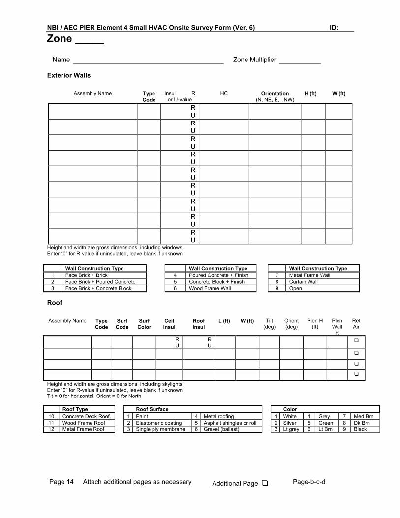
NBI / AEC PIER Element 4 Small HVAC Onsite Survey Form (Ver. 6) ID:
Page 14 Attach additional pages as necessary Additional Page ❏ Page-b-c-d
Zone _____
Name Zone Multiplier
Exterior Walls
Assembly Name Type Code
Insul R or U-value
HC Orientation (N, NE, E, ,NW)
H (ft) W (ft)
RU
RU
RU
RU
RU
RU
RU
RU
RU
Height and width are gross dimensions, including windows Enter “0” for R-value if uninsulated, leave blank if unknown
Wall Construction Type Wall Construction Type Wall Construction Type 1 Face Brick + Brick 4 Poured Concrete + Finish 7 Metal Frame Wall 2 Face Brick + Poured Concrete 5 Concrete Block + Finish 8 Curtain Wall 3 Face Brick + Concrete Block 6 Wood Frame Wall 9 Open
Roof Assembly Name Type
Code Surf Code
Surf Color
Ceil Insul
Roof Insul
L (ft) W (ft) Tilt (deg)
Orient (deg)
Plen H (ft)
Plen Wall
R
Ret Air
R U
R U
❏
❏
❏
❏
Height and width are gross dimensions, including skylights Enter “0” for R-value if uninsulated, leave blank if unknown Tit = 0 for horizontal, Orient = 0 for North
Roof Type Roof Surface Color 10 Concrete Deck Roof. 1 Paint 4 Metal roofing 1 White 4 Grey 7 Med Brn 11 Wood Frame Roof 2 Elastomeric coating 5 Asphalt shingles or roll 2 Silver 5 Green 8 Dk Brn 12 Metal Frame Roof 3 Single ply membrane 6 Gravel (ballast) 3 Lt grey 6 Lt Brn 9 Black

NBI / AEC PIER Element 4 Small HVAC Onsite Survey Form (Ver. 6) ID:
Page 15 Attach additional pages as necessary Additional Page ❏ Page-b-c-d
Zone _____ (contd) Window/Skylight Types
Ref. No. Assembly Name No. Panes
Glazing Type
Frame Type
Features (circle)
Meas.Trans. SHGC U- value
1 Low e / gas fill
2 Low e / gas fill
3 Low e / gas fill
4 Low e / gas fill
5 Low e / gas fill
6 Low e / gas fill
7 Low e / gas fill
8 Low e / gas fill
9 Low e / gas fill
10 Low e / gas fill
Glass Type Plastic Type Window Frame Type Skylight Frame Type
1 Clear 5 Clear Plastic 1 Standard Metal Frame 4 Standard Metal Frame w/ Curb 2 Tinted 6 Tinted Plastic 2 Thermally Broken Frame 5 Thermally Broken Frame w/ Curb 3 Reflective 7 White Plastic 3 Wood/Vinyl Frame 6 Standard Metal Frame w/o Curb 4 Fritted (diffusing) 8 Translucent 7 Thermally Broken Frame w/o Curb Window/Skylight Geometry Ref No.
Tilt Orient H (ft) W (ft) Qty Int. Shade Type
Otr Ex Shd%
OH Offset
OH Proj
Side Fin Ofst
Side Fin Proj
Skylite Shape
Oper?
Y/ N
Y/ N
Y/ N
Y/ N
Y/ N
Y/ N
Y/ N
Y/ N
Y/ N
Y/ N
Y/ N
Tit = 0 for horizontal, Orient = 0 for North. Tilt applies only to skylights. Side fins apply only to windows. Otr Ex Shd% refers to exterior shading from adjacent buildings, building self-shading, thick vegetation, hillsides etc. Interior Shade Type: 1 = Blinds; 2 = Light Shades or Drapes; 3 = Dark Shades or Drapes Skylight Shape: 1 = Domed; 2= Flat; 3= Pyramid; 4= Ridge; 5= Vault

NBI / AEC PIER Element 4 Small HVAC Onsite Survey Form (Ver. 6) ID:
Page 16 Attach additional pages as necessary Additional Page ❏ Page-b-c-d
Space _____ Name __________________ Floor Area_________SF
Corridor/Restroom/Support Area______% Space Multiplier______
Maximum Number of People___________
Circle appropriate occupancy code: 1 Auditorium 14 Office - Other 26 Hotel function 39 Gymnasium 2 Church /chapel 15 Computer center 27 Hotel guest room 40 Library 3 Convention, meeting 16 EEG/EKG/MRI/Radiation 28 Hotel lobby 41 Locker room 4 Courtroom 17 Hospital - Emergency 29 Barber, beauty shop 42 School shop 5 Exhibit 18 Hospital general area 30 Bowling alley 43 Swimming pool 6 Main entry lobby 19 Hospital laboratory 31 Coin op laundry 44 Aircraft hanger 7 Motion picture theater 20 Hosp.patient rm/ nursery 32 Comm’l dry cleaners 45 Auto repair workshop 8 Performance theater 21 Hosp. therapy (OT, PT) 33 Grocery 46 General C&I work, high bay 9 Bars, lounge, casino 22 Hospital Pharmacy 34 Mall, arcade, atrium 47 Precision C&I work 10 Dining 23 Hospital Radiology 35 Retail, whlse sales flr 48 Storage, warehouse 11 Kitchen 24 Hospital Recovery 36 Classroom 49 Other (Describe) 12 Bank/financial institution 25 Hosp. Surgical & OB suite 37 Day care 50 General C&I, low bay (<25 ft) 13 Medical / clinical office 38 Dormitory Note: Codes 16 – 25 are for hospitals only
Lighting
Name Fixture Code
Fixture Count Mount. Type
Track Length
Controls (circle all that apply)
% fix ctrl
% ctrl oper
1 / 2 / 3 / 4 ❏ EMS?
1 / 2 / 3 / 4 ❏ EMS?
1 / 2 / 3 / 4 ❏ EMS?
1 / 2 / 3 / 4 ❏ EMS?
1 / 2 / 3 / 4 ❏ EMS?
1 / 2 / 3 / 4 ❏ EMS?
1 / 2 / 3 / 4 ❏ EMS?
1 / 2 / 3 / 4 ❏ EMS?
1 / 2 / 3 / 4 ❏ EMS?
1 / 2 / 3 / 4 ❏ EMS?
1 / 2 / 3 / 4 ❏ EMS?
1 / 2 / 3 / 4 ❏ EMS?
Lighting Control Codes 1 = Occupancy sensor 2 = Daylight - contin. dimming 3 = Daylighting - stepped 4 = Lumen maintenance
Fixture Mounting Type Codes 1 = Rec 2 = Dir 3 = Ind 4 = Ind-Dir 5 = Plug-in Task 6 = Furn. Int. Task. 7 = Track 8 = Exempt

NBI / AEC PIER Element 4 Small HVAC Onsite Survey Form (Ver. 6) ID:
Page 17 Attach additional pages as necessary Additional Page ❏ Page-b-c-d
Space _____ contd Miscellaneous Equipment and Plug Loads
Name Equip. Code
Count Usage Factor
kW/ Unit or
Motor HP or
kBtuh Input
Under Hood?
Y / N
Y / N
Y / N
Y / N
Y / N
Y / N
Y / N
Y / N
Y / N
Y / N
Y / N Usage factor: Fraction of time equipment in use (0.0 – 1.0) to account for seldomly used equipment. Default is 1.0 Equipment - Record kW for equipment without default or if default is not appropriate
Equipment Description Equip Code
Default kW
Equipment Description Equip Code
Default kW
General Personal Computer w/ Monitor 1 0.5 Grocery Meat Grinder 21 7. Terminal 2 0.15 Meat Saw 22 2.5 Laser Printer 3 0.85 Meat Slicer 23 0.25 Small Copier 4 Wrapper 24 0.9 Medium Copier 5 Check stand 25 1.5 Large Copier 6 Hospital Laboratory Equipment 26 Fax Machine 7 0.1 Monitoring, Life Support 27 1.1 Mini-Computer + Periph 8 1.0 EEG 30 1.1 Main Frame Computer +
Periph 9 EKG 31 1.1
Microwave 10 1.7 MRI 32 26. Misc. Appliance 11 X-ray machine 33 5. Television 12 0.15 Radiation Therapy Machine 34 10. Washer 13 0.5 Indust Air Compressor 35 Dryer 14 4. Welder 36 Cash Register 15 0.15 Battery Charger 37 1.5 Box Crusher 16 10. Machine Tools 38 Gasoline pump 17 0.7 Motor 39 ATM 18 .5 Misc. Other 40 Video game 19 .5 Exercise equipment 20 .5
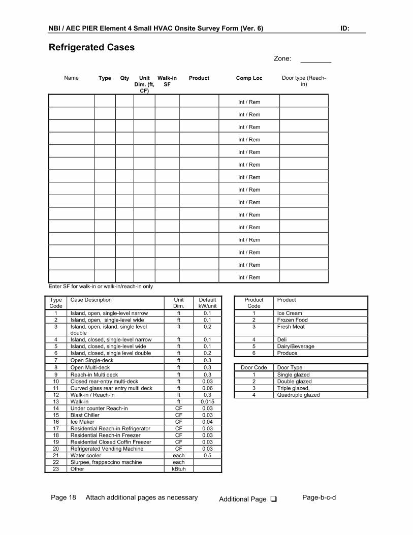
NBI / AEC PIER Element 4 Small HVAC Onsite Survey Form (Ver. 6) ID:
Page 18 Attach additional pages as necessary Additional Page ❏ Page-b-c-d
Refrigerated Cases Zone:
Name Type Qty Unit Dim. (ft,
CF)
Walk-in SF
Product Comp Loc Door type (Reach-in)
Int / Rem
Int / Rem
Int / Rem
Int / Rem
Int / Rem
Int / Rem
Int / Rem
Int / Rem
Int / Rem
Int / Rem
Int / Rem
Int / Rem
Int / Rem
Int / Rem
Int / Rem Enter SF for walk-in or walk-in/reach-in only Type Code
Case Description Unit Dim.
Default kW/unit
Product Code
Product
1 Island, open, single-level narrow ft 0.1 1 Ice Cream 2 Island, open, single-level wide ft 0.1 2 Frozen Food 3 Island, open, island, single level
double ft 0.2 3 Fresh Meat
4 Island, closed, single-level narrow ft 0.1 4 Deli 5 Island, closed, single-level wide ft 0.1 5 Dairy/Beverage 6 Island, closed, single level double ft 0.2 6 Produce 7 Open Single-deck ft 0.3 8 Open Multi-deck ft 0.3 Door Code Door Type 9 Reach-in Multi deck ft 0.3 1 Single glazed
10 Closed rear-entry multi-deck ft 0.03 2 Double glazed 11 Curved glass rear entry multi deck ft 0.06 3 Triple glazed, 12 Walk-in / Reach-in ft 0.3 4 Quadruple glazed 13 Walk-in ft 0.015 14 Under counter Reach-in CF 0.03 15 Blast Chiller CF 0.03 16 Ice Maker CF 0.04 17 Residential Reach-in Refrigerator CF 0.03 18 Residential Reach-in Freezer CF 0.03 19 Residential Closed Coffin Freezer CF 0.03 20 Refrigerated Vending Machine CF 0.03 21 Water cooler each 0.5 22 Slurpee, frappaccino machine each 23 Other kBtuh

NBI / AEC PIER Element 4 Small HVAC Onsite Survey Form (Ver. 6) ID:
Page 19 Attach additional pages as necessary Additional Page ❏ Page-b-c-d
Foodservice Zone: Kitchen Equipment
Appliance Name Qty Type Fuel KW or Volts / A
kBtuh I
Trade Size Hood
Elec. / Other / Y / N
Elec. / Other / Y / N
Elec. / Other / Y / N
Elec. / Other / Y / N
Elec. / Other / Y / N
Elec. / Other / Y / N
Elec. / Other / Y / N
Elec. / Other / Y / N
Elec. / Other / Y / N
Elec. / Other / Y / N
Elec. / Other / Y / N
Elec. / Other / Y / N
Hoods
Name Type Size (SF)
Flow (cfm)
Fan hp Makeup Air Source
Canopy / Island Canopy / Backshelf Cond / Uncond
Canopy / Island Canopy / Backshelf Cond / Uncond
Canopy / Island Canopy / Backshelf Cond / Uncond
Canopy / Island Canopy / Backshelf Cond / Uncond
Canopy / Island Canopy / Backshelf Cond / Uncond
Canopy / Island Canopy / Backshelf Cond / Uncond
Type Code
Description Trade size
Default kW/unit
Type Code
Description Trade size
Default kW/unit
1 Broiler (include cheesemelter)
ft 1.7 15 Oven, convection, combi, or retherm
doors 3.8
2 Char Broiler ft 3.7 16 Food warmer ft 0.6 3 Griddle, single sided ft 4.5 17 Heated display case ft 0.5 4 Griddle, clam shell ft 7.5 18 Microwave oven 1.7 5 Fryer, countertop lb 0.3 19 Toaster, pop-up 1.8 6 Fryer, free-standing lb 0.3 20 Toaster, conveyor 4.6 7 Fryer, pressure lb 0.3 21 Coffee pot burners 1. 8 Fryer, donut lb 0.3 22 Steam table ft 0.6 9 Kettle, Pasta cooker qt 0.25 23 Dishwasher, single tank racks/hr 0.3
10 Heat lamps lamps 0.5 24 Dishwasher, conveyor racks/hr 0.1 11 Range top ft 5. 25 Steam jacketed kettle qt 0.4 12 Oven, pizza or bake decks 7. 26 Braising pan/skillet qt 0.1 13 Oven, conveyor decks 13. 27 Other kW 14 Oven, range ft 2.

NBI / AEC PIER Element 4 Small HVAC Onsite Survey Form (Ver. 6) ID:
Page 20 Attach additional pages as necessary Additional Page ❏ Page-b-c-d
Pools/ Spas Name Location Surface
Area (SF)
Outside / Inside
Outside / Inside
Outside / Inside
Outside / Inside
Incidents Circle any incidents as applicable: 1 None to report 7 Contact person unavailable or unaware of survey appointment 2 Complaint about rates 8 Customer expressed dissatisfaction with survey (list reason(s)) 3 Complaint about energy costs or lack of savings 9 Property damage occurred during on-site survey 4 Complaint about outages or power quality 10 Personal injury occurred during on-site survey 5 Complaint about technology reliability 11 Other (list) 6 Complaint about utility customer service
Designers From the Mechanical plans, record the name, address and phone of the firm responsible for the mechanical design and Title 24 MECH compliance: Mechanical Designer:
Name: Address: Phone:
Title 24 MECH compliance:
Name: Address: Phone:
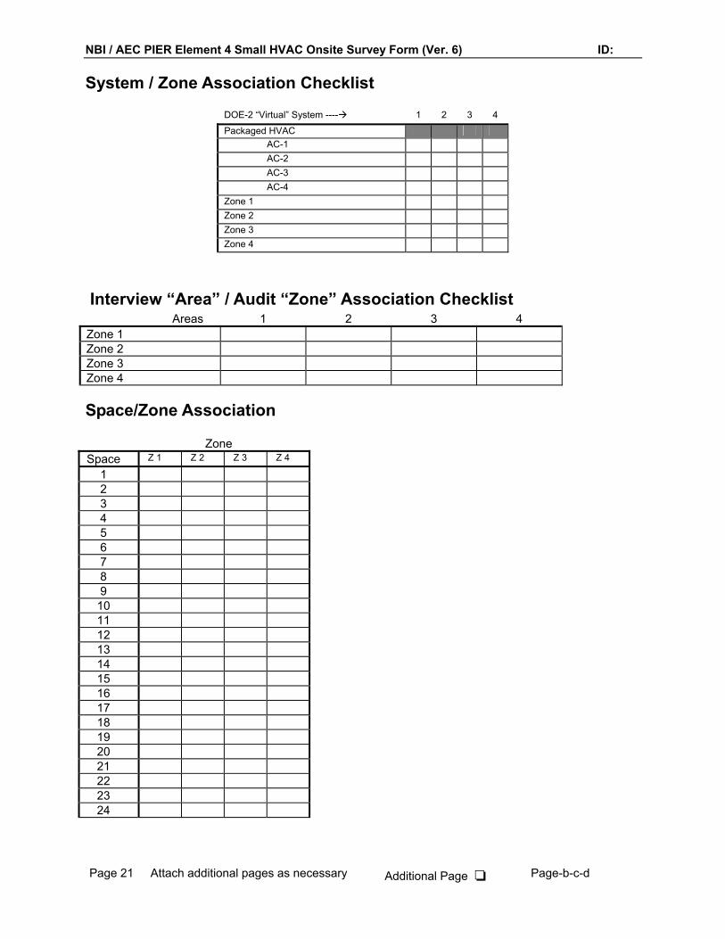
NBI / AEC PIER Element 4 Small HVAC Onsite Survey Form (Ver. 6) ID:
Page 21 Attach additional pages as necessary Additional Page ❏ Page-b-c-d
System / Zone Association Checklist
DOE-2 “Virtual” System ---- 1 2 3 4
Packaged HVAC AC-1 AC-2 AC-3 AC-4
Zone 1 Zone 2 Zone 3 Zone 4
Interview “Area” / Audit “Zone” Association Checklist Areas 1 2 3 4
Zone 1 Zone 2 Zone 3 Zone 4
Space/Zone Association
Zone Space Z 1 Z 2 Z 3 Z 4
1 2 3 4 5 6 7 8 9 10 11 12 13 14 15 16 17 18 19 20 21 22 23 24

California Energy Commission PIER Project Comfort Survey Ver. 1. Site ID_______Space #_____
Page 22 Attach additional pages as necessary Additional Page ❏ Page-b-c-d
Sketch of Building Floor Plan
Be sure to include dimensions, North arrow, and zone and HVAC equipment locations

California Energy Commission PIER Project Comfort Survey Ver. 1. Site ID_______Space #_____
Page 23 Attach additional pages as necessary Additional Page ❏ Page-b-c-d
Employee Survey of Thermal Comfort
This is a short survey of your personal comfort while at work. Think about your comfort throughout the year. Does it change seasonally? How do you feel about your comfort? It should take you just a minute or two to complete the survey.
1) While at work, are you comfortable (from a temperature standpoint)? None of the time Occasionally About half of the time
Most of the time All of the time
2) If you are uncomfortable, is it: (check any that may apply) Too Hot Too Cold
Too Drafty Air Quality is poor (odors, dust, etc.)
3) If you are uncomfortable, when does it occur? (check all that may apply) During the Winter During the Spring or
Fall During the Summer
Too Hot Too Hot Too Hot Too Cold
Too Cold Too Cold Drafty Drafty
Drafty
4) Does your work typically keep you at your desk/workstation: 20% of the time or less 20-40% of the time 40-60% of the time 60-80% of the time 80 % or more of the work day
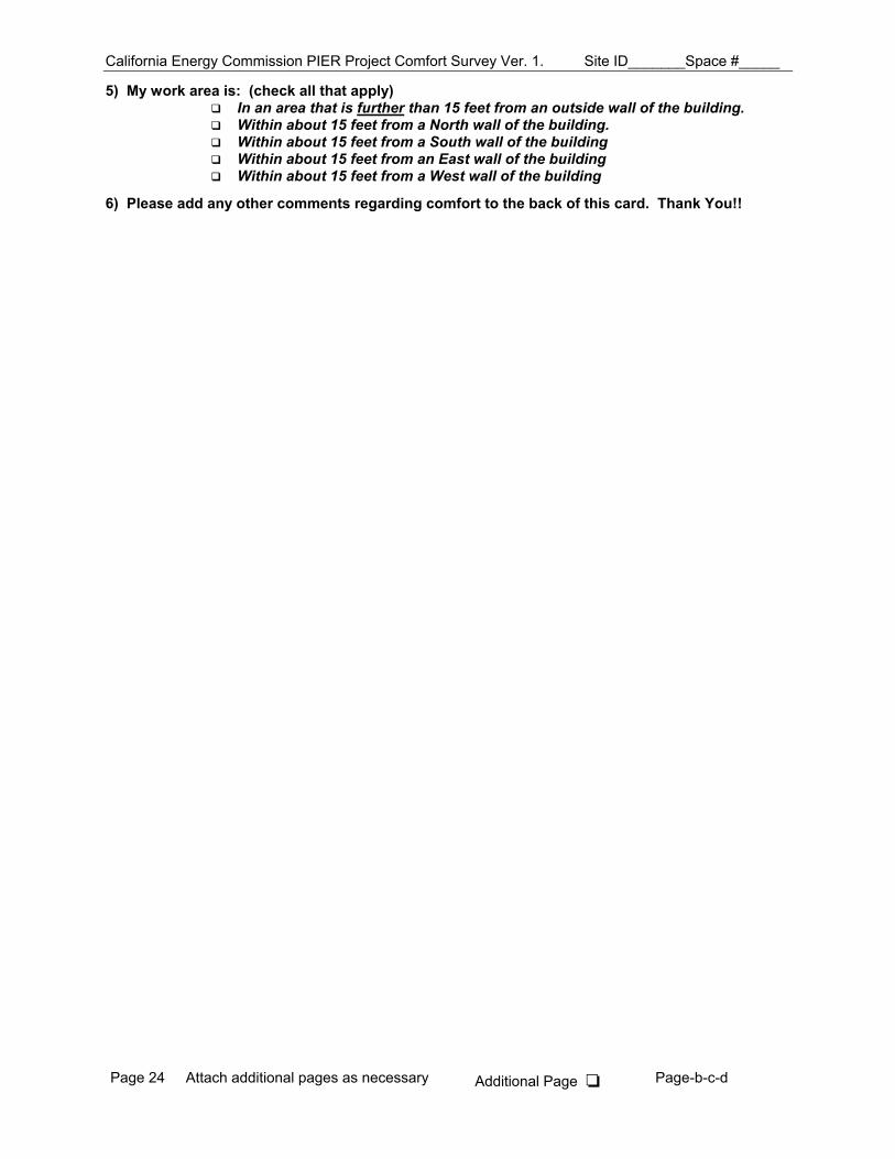
California Energy Commission PIER Project Comfort Survey Ver. 1. Site ID_______Space #_____
Page 24 Attach additional pages as necessary Additional Page ❏ Page-b-c-d
5) My work area is: (check all that apply) In an area that is further than 15 feet from an outside wall of the building. Within about 15 feet from a North wall of the building. Within about 15 feet from a South wall of the building Within about 15 feet from an East wall of the building Within about 15 feet from a West wall of the building
6) Please add any other comments regarding comfort to the back of this card. Thank You!!

PIER – Integrated Energy Systems: Productivity and Building Science
Functional Performance Test
CARRIER Single-Package RTU
High Efficiency Electric Cooling/ Gas Heating
with Durablade or Economizer Dry-bulb Economizer
Model# 48HJD/HJE/HJF
1. Prerequisite Checklist __ Onsite survey form complete __ Power is present at all involved equipment 2. Economizer Model Verification
Note the economizer make and model number.
3. Functional Performance Testing General Conditions of Test (date, time, ambient conditions, occupancy, etc.) 4. Preliminary Procedures First test that the economizer damper actuator is operational (this can only be performed on units with the Economi$er, not on Durablade units) Procedure: 1. Locate the economizer controller 2. Make a note as to the current location of the minimum damper position adjuster 3. Slowly move the adjuster CW and CCW and verify that the damper moves accordingly. If
the damper will not move, the unit fails the test and no further testing is necessary. If the damper moves with the adjuster, then proceed with the tests below. There may be a short delay before movement is witnessed.
4. Re-adjust the minimum damper position control to its original position. Ready the thermostat interface for jumper testing and install the MDL sensors Remove the wires from the connection board located in the RTU control panel that control the cooling and fan operation:
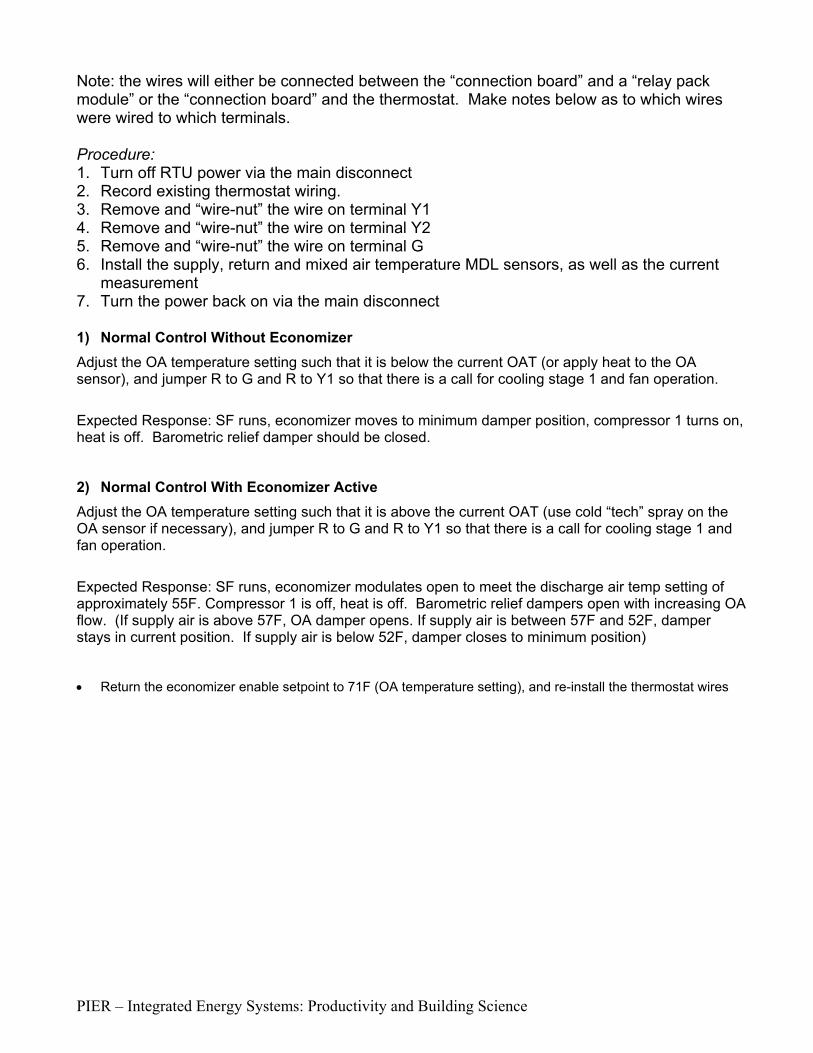
PIER – Integrated Energy Systems: Productivity and Building Science
Note: the wires will either be connected between the “connection board” and a “relay pack module” or the “connection board” and the thermostat. Make notes below as to which wires were wired to which terminals. Procedure: 1. Turn off RTU power via the main disconnect 2. Record existing thermostat wiring. 3. Remove and “wire-nut” the wire on terminal Y1 4. Remove and “wire-nut” the wire on terminal Y2 5. Remove and “wire-nut” the wire on terminal G 6. Install the supply, return and mixed air temperature MDL sensors, as well as the current
measurement 7. Turn the power back on via the main disconnect 1) Normal Control Without Economizer Adjust the OA temperature setting such that it is below the current OAT (or apply heat to the OA sensor), and jumper R to G and R to Y1 so that there is a call for cooling stage 1 and fan operation.
Expected Response: SF runs, economizer moves to minimum damper position, compressor 1 turns on, heat is off. Barometric relief damper should be closed.
2) Normal Control With Economizer Active
Adjust the OA temperature setting such that it is above the current OAT (use cold “tech” spray on the OA sensor if necessary), and jumper R to G and R to Y1 so that there is a call for cooling stage 1 and fan operation.
Expected Response: SF runs, economizer modulates open to meet the discharge air temp setting of approximately 55F. Compressor 1 is off, heat is off. Barometric relief dampers open with increasing OA flow. (If supply air is above 57F, OA damper opens. If supply air is between 57F and 52F, damper stays in current position. If supply air is below 52F, damper closes to minimum position)
• Return the economizer enable setpoint to 71F (OA temperature setting), and re-install the thermostat wires
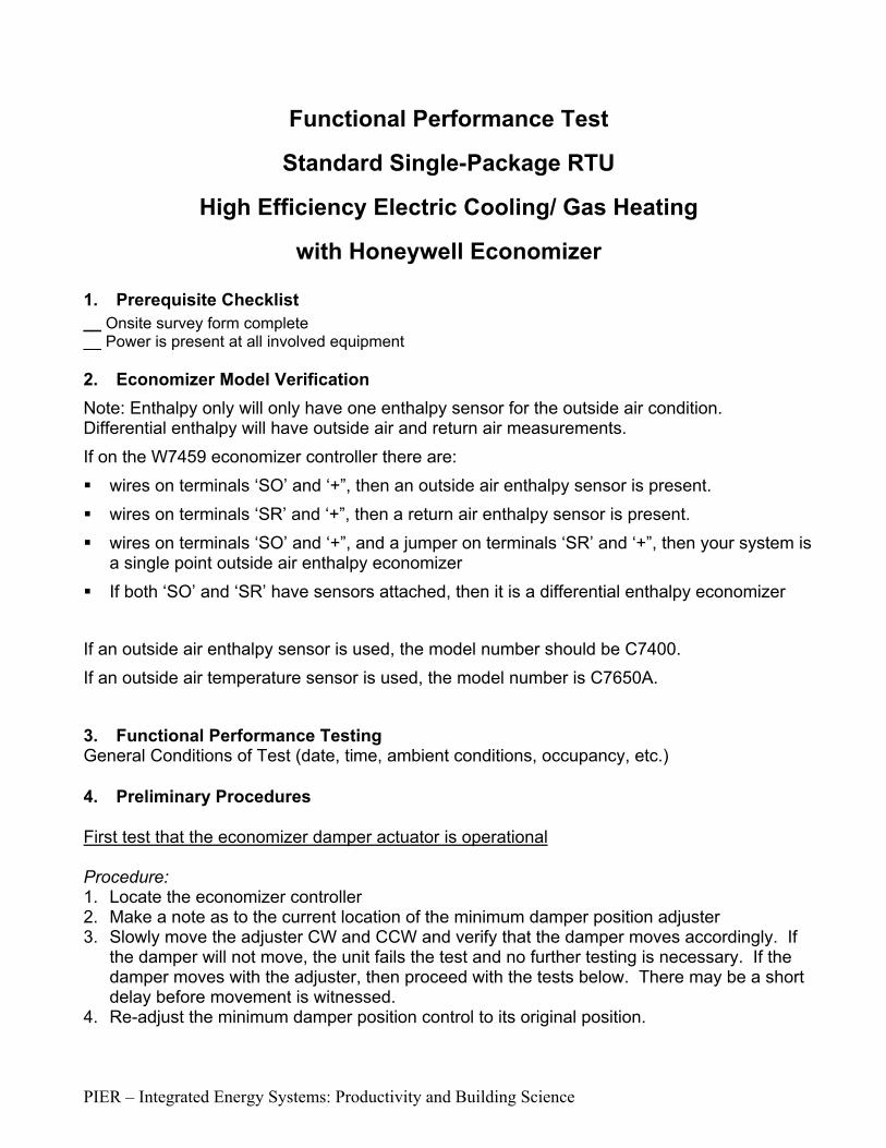
PIER – Integrated Energy Systems: Productivity and Building Science
Functional Performance Test
Standard Single-Package RTU
High Efficiency Electric Cooling/ Gas Heating
with Honeywell Economizer 1. Prerequisite Checklist __ Onsite survey form complete __ Power is present at all involved equipment 2. Economizer Model Verification Note: Enthalpy only will only have one enthalpy sensor for the outside air condition. Differential enthalpy will have outside air and return air measurements. If on the W7459 economizer controller there are: wires on terminals ‘SO’ and ‘+”, then an outside air enthalpy sensor is present. wires on terminals ‘SR’ and ‘+”, then a return air enthalpy sensor is present. wires on terminals ‘SO’ and ‘+”, and a jumper on terminals ‘SR’ and ‘+”, then your system is
a single point outside air enthalpy economizer If both ‘SO’ and ‘SR’ have sensors attached, then it is a differential enthalpy economizer
If an outside air enthalpy sensor is used, the model number should be C7400. If an outside air temperature sensor is used, the model number is C7650A.
3. Functional Performance Testing General Conditions of Test (date, time, ambient conditions, occupancy, etc.) 4. Preliminary Procedures First test that the economizer damper actuator is operational Procedure: 1. Locate the economizer controller 2. Make a note as to the current location of the minimum damper position adjuster 3. Slowly move the adjuster CW and CCW and verify that the damper moves accordingly. If
the damper will not move, the unit fails the test and no further testing is necessary. If the damper moves with the adjuster, then proceed with the tests below. There may be a short delay before movement is witnessed.
4. Re-adjust the minimum damper position control to its original position.

PIER – Integrated Energy Systems: Productivity and Building Science
Ready the thermostat interface for jumper testing and install the MDL sensors Remove the wires from the connection board located in the RTU control panel that control the cooling and fan operation: Note: the wires will likely be connected to the thermostat. Procedure: 1. Turn off RTU power via the main disconnect 2. Record existing thermostat wiring. 3. Remove and “wire-nut” the wire on terminal Y1 4. Remove and “wire-nut” the wire on terminal Y2 5. Remove and “wire-nut” the wire on terminal G 6. Install the supply, return and mixed air temperature MDL sensors, as well as the current
measurement 7. Turn the power back on via the main disconnect 1) Normal Control Without Economizer Change the enthalpy setting on the controller to ‘D’ for testing purposes.
Either warm-up or spray moisture near the OA enthalpy sensor (use a hot damp rag on the OA sensor if necessary) such that the enthalpy is above the lockout setpoint (or above the return air enthalpy sensor if present), and jumper R to G and R to Y1 so that there is a call for cooling stage 1 and fan operation.
Expected Response: SF runs, economizer moves to minimum damper position, compressor 1 turns on, heat is off. Barometric relief damper should be closed.
Note: The LED on the economizer controller lights when the OA is suitable for free cooling – during this test, the LED should be off.
2) Normal Control With Economizer Active
Change the enthalpy setting on the controller to ‘A’ for testing purposes. Be sure to return it to its original position when the tests are completed.
Cool down the OA enthalpy sensor (use cold “tech” spray near the OA sensor in the airstream if necessary) such that the enthalpy is below the lockout setpoint (or below the return air enthalpy sensor if present), and jumper R to G and R to Y1 so that there is a call for cooling stage 1 and fan operation.
Expected Response: SF runs, economizer modulates open to meet the discharge air temp setting of approximately 55F. Compressor 1 is off, heat is off. Barometric relief dampers open with increasing OA flow.
Note: The LED on the economizer controller lights when the OA is suitable for free cooling. If the LED does not illuminate properly, make note of this in your records.
• Return the economizer enable setpoint to its original setting, and re-install the thermostat wires

PIER – Integrated Energy Systems: Productivity and Building Science
Functional Performance Test
TRANE Single-Package RTU
High Efficiency Electric Cooling/ Gas Heating
with Economizer
Model# YCD/YCH
1. Prerequisite Checklist __ Onsite survey form complete __ Power is present at all involved equipment 2. Economizer Model Verification Locate the economizer controller “Unit Economizer Module” (UEM) – remove the fresh air adjustment panel located on the unit end panel to access the UEM. In the bottom left corner are terminals labeled J7,J8,J9,J10. If there are wires on any of these terminals then likely there is an enthalpy control instead of dry-bulb control present. Note the economizer make and model number. If on the UEM economizer controller there are: wires on terminals ‘J7’ and ‘J8’, then a return air enthalpy sensor is present. wires on terminals ‘J9’ and ‘J10’, then an outside air enthalpy sensor is present. If only outside air enthalpy sensor is present, then your system is a single point enthalpy
economizer If both air enthalpy sensors are present, then your system is a differential enthalpy
economizer If neither return or outside air enthalpy/humidity sensors are present, then it is a
temperature only economizer. The OA sensor is located near the condenser and is a small metal probe.
If an outside air enthalpy sensor is used, the model number should be C7600A. (it is actually a humidity sensor, because the TRANE unit measure outside air temperature from a different control module, located on the control board ‘UCP’, terminals J1-15 and J1-16)
3. Functional Performance Testing General Conditions of Test (date, time, ambient conditions, occupancy, etc.)
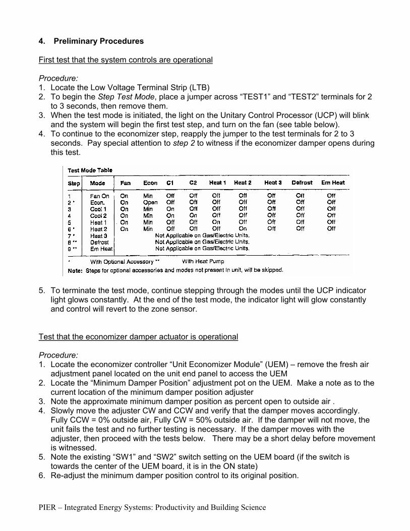
PIER – Integrated Energy Systems: Productivity and Building Science
4. Preliminary Procedures First test that the system controls are operational Procedure: 1. Locate the Low Voltage Terminal Strip (LTB) 2. To begin the Step Test Mode, place a jumper across “TEST1” and “TEST2” terminals for 2
to 3 seconds, then remove them. 3. When the test mode is initiated, the light on the Unitary Control Processor (UCP) will blink
and the system will begin the first test step, and turn on the fan (see table below). 4. To continue to the economizer step, reapply the jumper to the test terminals for 2 to 3
seconds. Pay special attention to step 2 to witness if the economizer damper opens during this test.
5. To terminate the test mode, continue stepping through the modes until the UCP indicator
light glows constantly. At the end of the test mode, the indicator light will glow constantly and control will revert to the zone sensor.
Test that the economizer damper actuator is operational Procedure: 1. Locate the economizer controller “Unit Economizer Module” (UEM) – remove the fresh air
adjustment panel located on the unit end panel to access the UEM 2. Locate the “Minimum Damper Position” adjustment pot on the UEM. Make a note as to the
current location of the minimum damper position adjuster 3. Note the approximate minimum damper position as percent open to outside air . 4. Slowly move the adjuster CW and CCW and verify that the damper moves accordingly.
Fully CCW = 0% outside air, Fully CW = 50% outside air. If the damper will not move, the unit fails the test and no further testing is necessary. If the damper moves with the adjuster, then proceed with the tests below. There may be a short delay before movement is witnessed.
5. Note the existing “SW1” and “SW2” switch setting on the UEM board (if the switch is towards the center of the UEM board, it is in the ON state)
6. Re-adjust the minimum damper position control to its original position.

PIER – Integrated Energy Systems: Productivity and Building Science
Install the MDL sensors Procedure: 1. Turn off RTU power via the main disconnect 2. Install the supply, return and mixed air temperature MDL sensors, as well as the current
measurement 3. Turn the power back on via the main disconnect The following tests require 2 people with communication radios to efficiently perform. If this is feasible, then continue with the tests. One person will need to be at the unit, and another at the thermostat.
1) Normal Control Without Economizer Adjust the OA economizer setting such that it is below the current OAT (moving SW1 to OFF, and SW2 to ON will result in a 55°F OA temperature setting), and adjust the thermostat down so there is a call for cooling stage 1 and fan operation
Expected Response: SF runs, economizer moves to minimum damper position, compressor 1 turns on, heat is off. Barometric relief damper should be closed.
2) Normal Control With Economizer Active
Adjust the OA temperature setting such that it is above the current OAT (use cold “tech” spray on the OA sensor if necessary), and adjust the thermostat down so there is a call for cooling stage 1 and fan operation (same as test#1 setting).
Note: Moving SW1 to ON, and SW2 to OFF will result in a 65°F OA temperature setting (and high enthalpy requirement), and/or use cold “tech” spray on the OA sensor if necessary.
Expected Response: SF runs, economizer modulates open to meet the discharge air temp setting of between 50F and 55F. Compressor 1 is off, heat is off. Barometric relief dampers open with increasing OA flow.
• Return the economizer enable switches (SW1 & SW2) to their original settings as noted on this page.
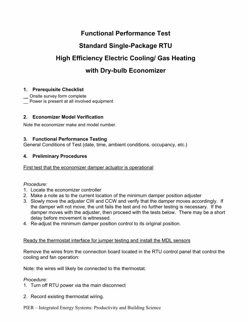
PIER – Integrated Energy Systems: Productivity and Building Science
Functional Performance Test
Standard Single-Package RTU
High Efficiency Electric Cooling/ Gas Heating
with Dry-bulb Economizer
1. Prerequisite Checklist __ Onsite survey form complete __ Power is present at all involved equipment 2. Economizer Model Verification
Note the economizer make and model number. 3. Functional Performance Testing General Conditions of Test (date, time, ambient conditions, occupancy, etc.) 4. Preliminary Procedures First test that the economizer damper actuator is operational Procedure: 1. Locate the economizer controller 2. Make a note as to the current location of the minimum damper position adjuster 3. Slowly move the adjuster CW and CCW and verify that the damper moves accordingly. If
the damper will not move, the unit fails the test and no further testing is necessary. If the damper moves with the adjuster, then proceed with the tests below. There may be a short delay before movement is witnessed.
4. Re-adjust the minimum damper position control to its original position. Ready the thermostat interface for jumper testing and install the MDL sensors Remove the wires from the connection board located in the RTU control panel that control the cooling and fan operation: Note: the wires will likely be connected to the thermostat. Procedure: 1. Turn off RTU power via the main disconnect 2. Record existing thermostat wiring.

PIER – Integrated Energy Systems: Productivity and Building Science
3. Remove and “wire-nut” the wire on terminal Y1 4. Remove and “wire-nut” the wire on terminal Y2 5. Remove and “wire-nut” the wire on terminal G 6. Install the supply, return and mixed air temperature MDL sensors, as well as the current
measurement 7. Turn the power back on via the main disconnect 1) Normal Control Without Economizer Adjust the OA temperature setting such that it is below the current OAT (or apply heat to the OA sensor), and jumper R to G and R to Y1 so that there is a call for cooling stage 1 and fan operation.
Expected Response: SF runs, economizer moves to minimum damper position, compressor 1 turns on, heat is off. Barometric relief damper should be closed.
2) Normal Control With Economizer Active
Adjust the OA temperature setting such that it is above the current OAT (use cold “tech” spray on the OA sensor if necessary), and jumper R to G and R to Y1 so that there is a call for cooling stage 1 and fan operation.
Expected Response: SF runs, economizer modulates open to meet the discharge air temp setting of approximately 55F. Compressor 1 is off, heat is off. Barometric relief dampers open with increasing OA flow.
Return the economizer enable setpoint to 71F (OA temperature setting), and re-install the thermostat wires
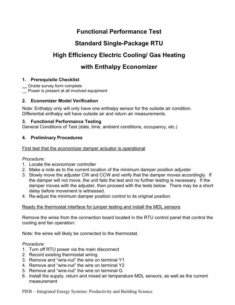
PIER – Integrated Energy Systems: Productivity and Building Science
Functional Performance Test
Standard Single-Package RTU
High Efficiency Electric Cooling/ Gas Heating
with Enthalpy Economizer 1. Prerequisite Checklist __ Onsite survey form complete __ Power is present at all involved equipment 2. Economizer Model Verification Note: Enthalpy only will only have one enthalpy sensor for the outside air condition. Differential enthalpy will have outside air and return air measurements.
3. Functional Performance Testing General Conditions of Test (date, time, ambient conditions, occupancy, etc.) 4. Preliminary Procedures First test that the economizer damper actuator is operational Procedure: 1. Locate the economizer controller 2. Make a note as to the current location of the minimum damper position adjuster 3. Slowly move the adjuster CW and CCW and verify that the damper moves accordingly. If
the damper will not move, the unit fails the test and no further testing is necessary. If the damper moves with the adjuster, then proceed with the tests below. There may be a short delay before movement is witnessed.
4. Re-adjust the minimum damper position control to its original position. Ready the thermostat interface for jumper testing and install the MDL sensors Remove the wires from the connection board located in the RTU control panel that control the cooling and fan operation: Note: the wires will likely be connected to the thermostat. Procedure: 1. Turn off RTU power via the main disconnect 2. Record existing thermostat wiring. 3. Remove and “wire-nut” the wire on terminal Y1 4. Remove and “wire-nut” the wire on terminal Y2 5. Remove and “wire-nut” the wire on terminal G 6. Install the supply, return and mixed air temperature MDL sensors, as well as the current
measurement

PIER – Integrated Energy Systems: Productivity and Building Science
7. Turn the power back on via the main disconnect 1) Normal Control Without Economizer Either warm-up or spray moisture near the OA enthalpy sensor (use a hot damp rag on the OA sensor if necessary) such that the enthalpy is above the lockout setpoint (or above the return air enthalpy sensor if present), and jumper R to G and R to Y1 so that there is a call for cooling stage 1 and fan operation.
Expected Response: SF runs, economizer moves to minimum damper position, compressor 1 turns on, heat is off. Barometric relief damper should be closed.
2) Normal Control With Economizer Active
Cool down the OA enthalpy sensor (use cold “tech” spray near the OA sensor if necessary) such that the enthalpy is below the lockout setpoint (or below the return air enthalpy sensor if present), and jumper R to G and R to Y1 so that there is a call for cooling stage 1 and fan operation.
Expected Response: SF runs, economizer modulates open to meet the discharge air temp setting of approximately 55F. Compressor 1 is off, heat is off. Barometric relief dampers open with increasing OA flow.
• Return the economizer enable setpoint to its original setting, and re-install the thermostat wires

Power Measurements October 11, 2001
PIER – Integrated Energy Systems: Productivity and Building Science
Spot power measurements for 3-phase delta connected loads (Nearly all 3-phase motors fit this category): There are two techniques described here. For consistency, use the phase to neutral method unless the ground is not reliable. Using the Phase-to-neutral method gives you a direct indication of power factor. Use the Phase-to-phase method only if a good neutral or ground connection cannot be established. Phase-to-neutral method: Technically, there isn’t a neutral available to perform this technique. However, the ground can often be substituted if there’s a good connection between ground and the neutral in the building. Three power measurements are required. Here’s the step-by-step procedure when using a single-phase power meter (All our fluke power meters are single-phase meters):
1. Connect the black voltage lead to Neutral (or ground)
2. Connect the red voltage lead to Phase A
3. Connect the current clamp to Phase A, being sure to verify that the clamp is facing the right direction. Click the phase check button on the fluke to verify proper connection.
4. Read and record the power voltage, current, and power factor measurement
5. Move the voltage lead and current clamp to Phase B and repeat step 4.
6. Move the voltage lead and current clamp to Phase C and repeat step 4.
7. Disconnect the voltage leads
Phase-to-phase method: Only two power measurements are required. Here’s the step-by-step procedure when using a single-phase power meter (All our fluke power meters are single-phase meters):
1. Connect the black voltage lead to Phase B
2. Connect the red voltage lead to Phase A
3. Connect the current clamp to Phase A, being sure to verify that the clamp is facing the right direction. Click the phase check button on the fluke to verify proper connection.
4. Read and record the power measurement
5. Read and record the current measurement for Phase A
6. Read and record the voltage measurement for Phase A-B

Power Measurements October 11, 2001
PIER – Integrated Energy Systems: Productivity and Building Science
7. Move the red voltage lead from Phase A to Phase C. Leave the black voltage lead on Phase B.
8. Move the current clamp to Phase C, being sure to verify that the clamp is facing the right direction. Click the phase check button on the fluke to verify proper connection.
9. Read and record the power measurement
10. Read and record the current measurement for Phase C
11. Read and record the voltage measurement for Phase C-B
12. Move the current clamp to Phase B
13. Read and record the current measurement for Phase B.
14. Disconnect the voltage leads
Methods for measuring power on single-phase loads connected phase-to-phase (many condenser and supply fans fall in this category): This can be accomplished in two ways. Either technique can be used. Regardless of the technique used, NOTE ON THE FORM that this is a single-phase load operating phase-to-phase. Use the phase-to-neutral method, described above. Since there are only two connections to the load, only two power measurements are required. Use the phase-to-phase method, described above, using the unused phase as the reference. It may or may not be Phase B. The following technique does not work, although intuitively it seems like it should work properly. Don’t use it: Take a single measurement of current, voltage, power factor, and power with the voltage leads connected to the phases serving the load. This method does not provide a good measurement of power factor.

NBI SMALL HVAC ECONOMIZER TEST DATASite ID# Date
Building Name General outside air conditions
Participants
RTU Name/ number
RTU Manufacturer
Economizer Present? (Y/N)
Economizer Make and Model#
Economizer setpoint setting (A,B,C,D or switches SW1, SW2)
Minimum OA damper position (%)
Record the minimim damper position adjuster setting
Does the actuator move, and the linkage operate? (Y/N)
Economizer type: (check one)single point temperaturedifferential temperature
single point enthalpydifferential enthalpy
Thermostat Wire Colors:R - power
G - Fan
Y1 - Cool stage 1
Y2 - Cool stage 2
Are there jumpers between the thermostat wire? Note which wires.
Does the economizer respond to cold air on the sensor? (Y/N)CEC/NBI PIER Project 12/2001