small magnetic loop antenna...
TRANSCRIPT

WA4MNT Small Transmitting Magnetic Loop Antenna Project
30m, 20m, 17m, 15m, 12m, 10m Bands
With the solar cycle improving, I wanted to build an efficient HF antenna for the upper bands that I could easily throw in the trunk of the car and operate quickly with a minimum of setup time. I decided on a small magnetic loop antenna after researching the subject on the web and reading the following statement from VK5KLT’s article on small magnetic loop antennas.
“A properly designed and constructed small loop of nominal 1m diameter will outperform any antenna type except a tri-band beam on the 10m/15m/20m bands, and will be within an S-unit (6db) or so of an optimised mono-band 3-element beam that’s mounted at an appropriate height above ground.”
There is a wealth of information on small magnetic loop antenna construction on the web. One of the best sources I found was by AA5TB, http://www.aa5tb.com/loop.html, and VK5KLT, http://www.brisdance.com/vk4amz/files/Download/UnderMagLoop.pdf . The antenna I built is a compilation of ideas I borrowed from many sources, gleaned from the work of others, and a little redesign.

This project resulted in a three foot diameter copper loop mounted on a small pedestal, with continuous coverage of 30m through 10m bands (10MHz-30MHz). I have been able to obtain an SWR of 1:1 - 1.2:1 over the entire range. Based on the advice of the most successful builders, I chose copper as the metal of choice and all joints are silver soldered to reduce the interconnection resistance. I chose to design my own trombone style capacitor (~10pF - ~110pF), and shielded Faraday Loop input. I used copper tubing, readily available low loss dielectric materials, PEX (cross linked polyethylene) tubing for the capacitor insulator, UHMW plastic (Polypropylene) for all other RF exposed parts, and non magnetic hardware for all mechanical fastening. My design was based on AA5TB’s on-line calculator, http://www.aa5tb.com/aa5tb_loop_v1.22a.xls, and my dielectric spacing exceeds a 2KW rating. I chose to mount my portable loop, a little less than one diameter, off the ground, from the bottom of the loop, with six radials, two loop diameters long, from the base. These antennas are high-Q resonant circuits. Many kilovolts can be present across the capacitor, and produce concentrated electro-magnetic radiation even at low power levels. For safety, maintain a minimum of 6 feet away from the antenna, while transmitting. I have access to milling and lathe equipment, so my exact approach may not be suitable for many amateurs; however many good designs are available using butterfly or vacuum capacitors and easier available tools. Even simpler monoband designs may be more appropriate. I incorporated a motor drive for remote tuning with a wired control cable. With the antenna bandwidth being so narrow, tuning for maximum receiver noise yields almost optimum SWR. I use no antenna tuner between the radio and antenna. I am not an antenna theoretician; my expertise is in mechanical design. I have attached all my detailed .pdf’s and defer to the complete VK5KLT “An Overview of the Underestimated Magnetic Loop HF Antenna” article at the end of this document for the theory of operation.
Results using my MFJ-259B antenna analyzer: 10m - 28.700 SWR 1.2 : 1 R=53, X=10 28.200 SWR 1.1 : 1 R=46, X=8 12m – 24.900 SWR 1.2 : 1 R=56, X=9 15m – 21.300 SWR 1 : 1 R=47, x=0
21.060 SWR 1 : 1 R=43, X=0 17m – 18.150 SWR 1.2 : 1 R=43, X=7 20m – 14.250 SWR 1.1 : 1 R=43, X=0 14.060 SWR 1.1 : 1 R=44, X=0 30m – 10.125 SWR 1.1 : 1 R=50, X=8 Small magnetic loops typically have 5 dBi gain when used with two loop diameter length radials. They exhibit a vertically polarized signal at the horizon and horizontally polarized signal overhead. Thank you to all the amateurs that have shared their wisdom and made the information public on the internet to make this project a success. You may consider joining the Yahoo groups, MagneticLoopAntenna or MagLoop Ken - WA4MNT www.qrpbuilder.com E-mail – [email protected]

Trombone style capacitor ~10pF – ~110pF
Shielded Faraday input loop
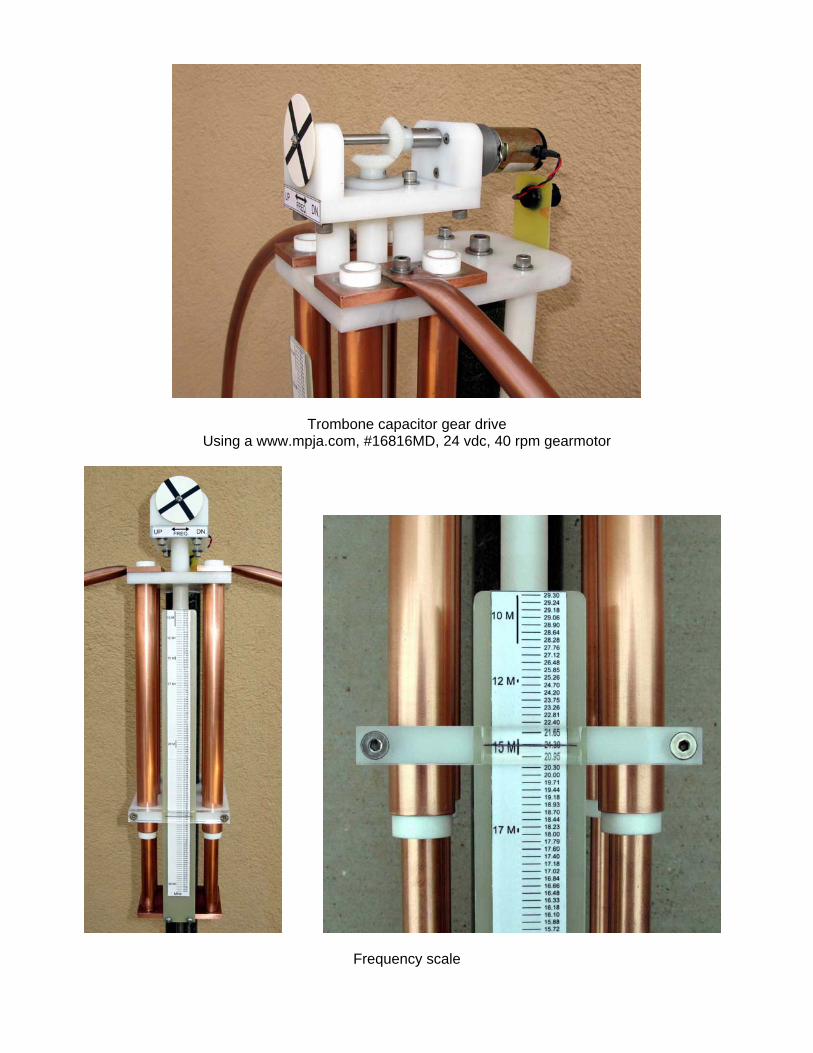
Trombone capacitor gear drive Using a www.mpja.com, #16816MD, 24 vdc, 40 rpm gearmotor
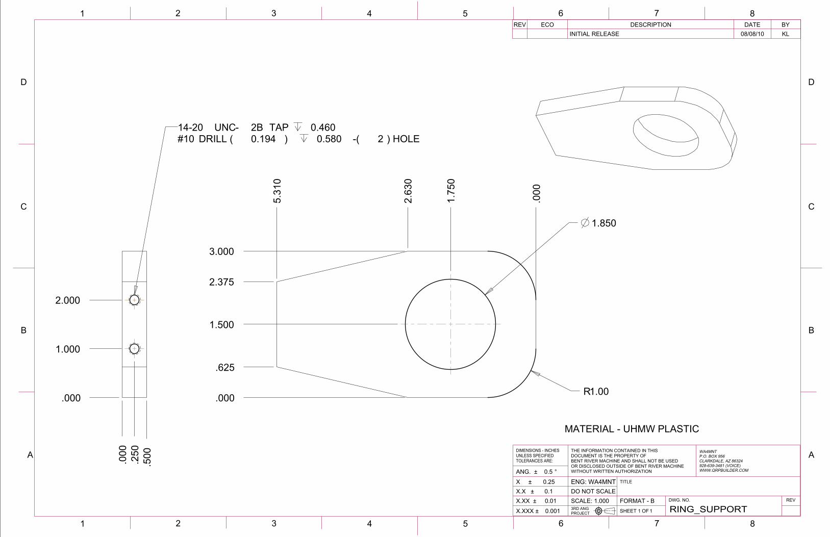
Frequency scale

Base with thumbscrews for 6’ radials, and surplus fiberglass mast section.
Motor controller and cables 12v gel cell transceiver supply, with 12v to 24v switching supply DC-DC module, www.lightobject.com for the gearmotor drive

Set up for operation
Small enough to fit in the trunk of my Toyota Corolla

12v -24v switcher for gearmotor
Motor controller, direction and speed
www.mpja.com, #16816MD, 24v, 40 rpm gearmotor

Common Plastics Dissipation Factor Chart
This will aid you in selecting suitable plastics for loop construction. Look for plastics with low dissipation factors. G10 /G11 glass epoxy board have a poor dissipation factor, 0.018, similar to PVC. UHMW (Polypropylene) is one tenth the cost of PTFE (Teflon).

2
B
1 3 4 7 865
21 3 4 7 865
A
C
D
B
A
C
D
LOOP_ASSYSHEET 1 OF 33RD ANGPROJECTX.XXX �# 0.001
REVDWG. NO.FORMAT - BSCALE: 0.048X.XX �# 0.01DO NOT SCALEX.X �# 0.1
WA4MNT 3' SMALL MAGNETICLOOP ANTENNA 30m-10m
TITLEENG: WA4MNTX �# 0.25
WA4MNTP.O. BOX 956CLARKDALE, AZ 86324928-639-3481 (VOICE)WWW.QRPBUILDER.COM
THE INFORMATION CONTAINED IN THISDOCUMENT IS THE PROPERTY OFBENT RIVER MACHINE AND SHALL NOT BE USEDOR DISCLOSED OUTSIDE OF BENT RIVER MACHINEWITHOUT WRITTEN AUTHORIZATIONANG. �# 0.5
DIMENSIONS - INCHESUNLESS SPECIFIEDTOLERANCES ARE:
BYDATEDESCRIPTIONECOREVKL08/08/10INITIAL RELEASE
NOTES:
ALL COPPER ANTENNA ELEMENTS JOINED BY SILVER SOLDERANY FASTENERS USED MUST BE 300 SERIES S.S.OPTIMUM HEIGHT IS TWO LOOP DIAMETERS ABOVE GROUNDOPTIMUM RADIALS ARE ~2 LOOP DIAMETERS LONG
THESE ANTENNAS ARE HIGH-Q RESONANT CIRCUITS.MANY KILOVOLTS CAN BE PRESENT ACROSS THE CAPACITOR,AND PRODUCE CONCENTRATED ELECTRO-MAGNETICRADAITION EVEN AT LOW POWER LEVELS. FOR SAFETY,MAINTAIN A MINIMUM OF 6' AWAY FROM THE ANTENNAWHILE TRANSMITTING.
CAUTION !!!
TROMBONE STYLECAPACITOR
`15pF - 80pF
SEE DETAIL A
SEE DETAIL B
SEE DETAIL C
SEE DETAIL D
1.825" O.D. FIBERGLASS MAST SECTION(MILITARY SURPLUS)
ALUMINUM BASE PLATE
SEE DETAIL A
SEE DETAIL B
SEE DETAIL C
SEE DETAIL D

2
B
1 3 4 7 865
21 3 4 7 865
A
C
D
B
A
C
D
LOOP_ASSYSHEET 2 OF 33RD ANGPROJECTX.XXX �# 0.001
REVDWG. NO.FORMAT - BSCALE: 0.048X.XX �# 0.01DO NOT SCALEX.X �# 0.1
WA4MNT 3' SMALL MAGNETICLOOP ANTENNA 30m-10m
TITLEENG: WA4MNTX �# 0.25
WA4MNTP.O. BOX 956CLARKDALE, AZ 86324928-639-3481 (VOICE)WWW.QRPBUILDER.COM
THE INFORMATION CONTAINED IN THISDOCUMENT IS THE PROPERTY OFBENT RIVER MACHINE AND SHALL NOT BE USEDOR DISCLOSED OUTSIDE OF BENT RIVER MACHINEWITHOUT WRITTEN AUTHORIZATIONANG. �# 0.5
DIMENSIONS - INCHESUNLESS SPECIFIEDTOLERANCES ARE:
BYDATEDESCRIPTIONECOREVKL08/08/10INITIAL RELEASE
0.750SCALE ADETAIL
WWW.MPJA.COMMOTOR #16816 MD12 VDC, 40 RPM
ROTATION INDICATOR
2 EA. MCM 7297K15 BEVEL GEARS & 2EA. .093 X .62 L. SS ROLL PINS
MOTOR MOUNT
CONNECTORBRACKET
ADJUSTMENT PLATE
SHAFTSUPPORT
GEARSHAFT
GEARSHAFTSPACER &
SHORTGEARSHAFT
2EA. ADJUSTMENTSPACER
UPPER STATORSUPPORT
2EA. STATORASSEMBLY
ANTENNA RING
2EA. STATORSPACER
0.750SCALE BDETAIL
4EA. STATORINSULATOR
LOWER STATORSUPPORT
2EA. STATOR SPACER
POINTER

2
B
1 3 4 7 865
21 3 4 7 865
A
C
D
B
A
C
D
LOOP_ASSYSHEET 3 OF 33RD ANGPROJECTX.XXX �# 0.001
REVDWG. NO.FORMAT - BSCALE: 0.048X.XX �# 0.01DO NOT SCALEX.X �# 0.1
WA4MNT 3' SMALL MAGNETICLOOP ANTENNA 30m-10m
TITLEENG: WA4MNTX �# 0.25
WA4MNTP.O. BOX 956CLARKDALE, AZ 86324928-639-3481 (VOICE)WWW.QRPBUILDER.COM
THE INFORMATION CONTAINED IN THISDOCUMENT IS THE PROPERTY OFBENT RIVER MACHINE AND SHALL NOT BE USEDOR DISCLOSED OUTSIDE OF BENT RIVER MACHINEWITHOUT WRITTEN AUTHORIZATIONANG. �# 0.5
DIMENSIONS - INCHESUNLESS SPECIFIEDTOLERANCES ARE:
BYDATEDESCRIPTIONECOREVKL08/08/10INITIAL RELEASE
0.750SCALE CDETAIL
SCALE
NUT
ROTOR ASSEMBLY
SCALESPACER
LEADSCREW
0.500SCALE DDETAIL
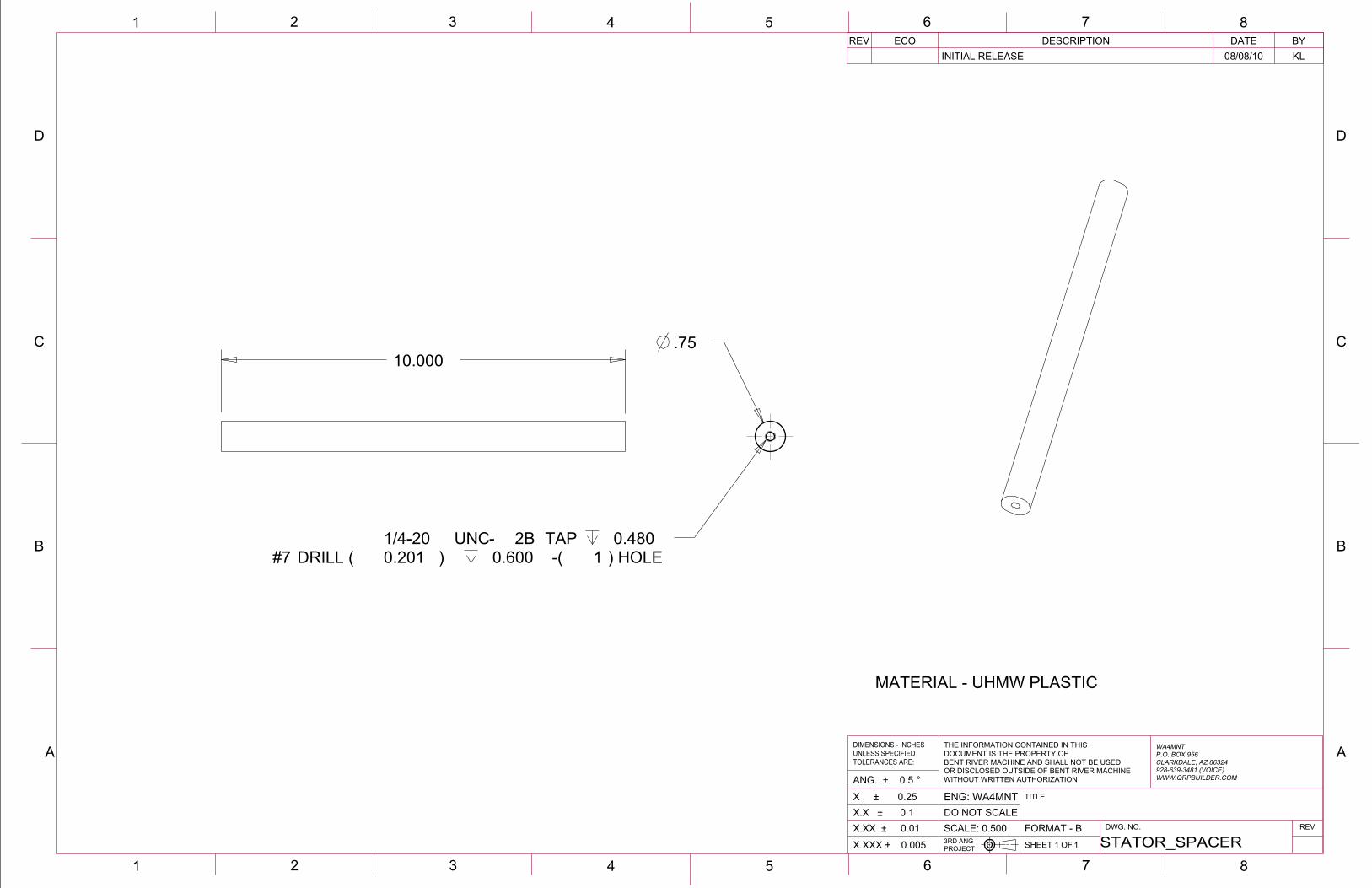
RING SUPPORT
INPUT FLANGE
SO-239
FARADAY LOOP ASSEMBLY
ANTENNA RING
SILVER SOLDER THE INPUT FLANGE TOTHE ANTENNA RING ON THE BACKSIDE

2
B
1 3 4 7 865
21 3 4 7 865
A
C
D
B
A
C
D
.72
.50 REF.
1.00 REF.
BYDATEDESCRIPTIONECOREVKL08/07/10INITIAL RELEASEBYDATEDESCRIPTIONECOREV
FARADAY_LOOPSHEET 1 OF 13RD ANGPROJECTX.XXX ± 0.001
REVDWG. NO.FORMAT - BSCALE: 0.500X.XX ± 0.01DO NOT SCALEX.X ± 0.1
TITLEENG: WA4MNTX ± 0.25
WA4MNTP.O. BOX 956CLARKDALE, AZ 86324928-639-3481 (VOICE)WWW.QRPBUILDER.COM
THE INFORMATION CONTAINED IN THISDOCUMENT IS THE PROPERTY OFBENT RIVER MACHINE AND SHALL NOT BE USEDOR DISCLOSED OUTSIDE OF BENT RIVER MACHINEWITHOUT WRITTEN AUTHORIZATIONANG. ± 0.5 °
DIMENSIONS - INCHESUNLESS SPECIFIEDTOLERANCES ARE:
BYDATEDESCRIPTIONECOREVKL08/08/10INITIAL RELEASE
1.000SCALE
INSIDE CONDUCTOR ANDINSULATOR OF RG-8 COAXSLIP FIT INTO SHELL
SILVER SOLDER AND DRILL PLUG TO ACCEPTRG-8 CENTER CONDUCTOR, SOLDER CENTER
CONDUCTOR TO PLUG
SILVER SOLDER BOTH PLATES TO SHELL
AT FINAL ASSEMBLY SOLDER RG-8 CENTER CONDUCTOR TO CENTER OF SO-239 CONNECTOR
FARADAY SHELL
FARADAY FLANGE

2
B
1 3 4 7 865
21 3 4 7 865
A
C
D
B
A
C
D
ROTOR_ASSEMBLYSHEET 1 OF 13RD ANGPROJECTX.XXX ± 0.001
REVDWG. NO.FORMAT - BSCALE: 0.250X.XX ± 0.01DO NOT SCALEX.X ± 0.1
TITLEENG: WA4MNTX ± 0.25
WA4MNTP.O. BOX 956CLARKDALE, AZ 86324928-639-3481 (VOICE)WWW.QRPBUILDER.COM
THE INFORMATION CONTAINED IN THISDOCUMENT IS THE PROPERTY OFBENT RIVER MACHINE AND SHALL NOT BE USEDOR DISCLOSED OUTSIDE OF BENT RIVER MACHINEWITHOUT WRITTEN AUTHORIZATIONANG. ± 0.5 °
DIMENSIONS - INCHESUNLESS SPECIFIEDTOLERANCES ARE:
BYDATEDESCRIPTIONECOREVKL08/08/10INITIAL RELEASE
SILVER SOLDER 4 PLACES
4EA. ROTOR - 1/2" RIGID COPPER TUBING
ROTOR UNION
SILVER SOLDER 4 PLACES
PRESS IN4EA. ROTOR PLUG
NUT W/4 EA. 6-32 FH SCREWS
LOWER LEADSCREW WASHER& 6-32 SCREW
UPPER LEADSCREW WASHER& .25 SNAP RING
LEADSCREW

2
B
1 3 4 7 865
21 3 4 7 865
A
C
D
B
A
C
D
12.50
STATOR_ASSEMBLYSHEET 1 OF 13RD ANGPROJECTX.XXX ± 0.001
REVDWG. NO.FORMAT - BSCALE: 0.333X.XX ± 0.01DO NOT SCALEX.X ± 0.1
TITLEENG: WA4MNTX ± 0.25
WA4MNTP.O. BOX 956CLARKDALE, AZ 86324928-639-3481 (VOICE)WWW.QRPBUILDER.COM
THE INFORMATION CONTAINED IN THISDOCUMENT IS THE PROPERTY OFBENT RIVER MACHINE AND SHALL NOT BE USEDOR DISCLOSED OUTSIDE OF BENT RIVER MACHINEWITHOUT WRITTEN AUTHORIZATIONANG. ± 0.5 °
DIMENSIONS - INCHESUNLESS SPECIFIEDTOLERANCES ARE:
BYDATEDESCRIPTIONECOREVKL08/08/10INITIAL RELEASE
2 PIECES REQUIRED
0.750SCALE
5/8" I.D. "PEX" TUBING (ACE HDWR)SLIP FIT IN STATOR TUBE
STATOR SILVER SOLDER 2 PLACES STATOR UNION

2
B
1 3 4 7 865
21 3 4 7 865
A
C
D
B
A
C
D.50
1.00 NOTE: THIS DIAMETER IS DETERMINED BY EXPERIMENTATIONAND IS APPROXIMATELY 1/5 LOOP DIAMETER
6.50
FARADAY_SHELLSHEET 1 OF 13RD ANGPROJECTX.XXX ± 0.001
REVDWG. NO.FORMAT - BSCALE: 0.500X.XX ± 0.01DO NOT SCALEX.X ± 0.1
TITLEENG: WA4MNTX ± 0.25
WA4MNTP.O. BOX 956CLARKDALE, AZ 86324928-639-3481 (VOICE)WWW.QRPBUILDER.COM
THE INFORMATION CONTAINED IN THISDOCUMENT IS THE PROPERTY OFBENT RIVER MACHINE AND SHALL NOT BE USEDOR DISCLOSED OUTSIDE OF BENT RIVER MACHINEWITHOUT WRITTEN AUTHORIZATIONANG. ± 0.5 °
DIMENSIONS - INCHESUNLESS SPECIFIEDTOLERANCES ARE:
BYDATEDESCRIPTIONECOREVKL08/08/10INITIAL RELEASE
MATERIAL - 3/8" O.D., 5/16" I.D. SOFT COPPER TUBING
1.000SCALE

2
B
1 3 4 7 865
21 3 4 7 865
A
C
D
B
A
C
D
.625
.625
.50
4X R.06
2X .125
.721.00
.50
.86
.14.03
FARADAY_FLANGESHEET 1 OF 13RD ANGPROJECTX.XXX ± 0.001
REVDWG. NO.FORMAT - BSCALE: 3.000X.XX ± 0.01DO NOT SCALEX.X ± 0.1
TITLEENG: WA4MNTX ± 0.25
WA4MNTP.O. BOX 956CLARKDALE, AZ 86324928-639-3481 (VOICE)WWW.QRPBUILDER.COM
THE INFORMATION CONTAINED IN THISDOCUMENT IS THE PROPERTY OFBENT RIVER MACHINE AND SHALL NOT BE USEDOR DISCLOSED OUTSIDE OF BENT RIVER MACHINEWITHOUT WRITTEN AUTHORIZATIONANG. ± 0.5 °
DIMENSIONS - INCHESUNLESS SPECIFIEDTOLERANCES ARE:
BYDATEDESCRIPTIONECOREVKL08/08/10INITIAL RELEASE
MATERIAL - COPPER2 REQUIRED

2
B
1 3 4 7 865
21 3 4 7 865
A
C
D
B
A
C
D
.76
6X .257
.250
.000
.750
1.75
0
2.75
0
3.75
04.
000
.500
.000
1.250
2.000
2.500
.50
ADJUSTMENT_PLATESHEET 1 OF 13RD ANGPROJECTX.XXX ± 0.001
REVDWG. NO.FORMAT - BSCALE: 1.000X.XX ± 0.01DO NOT SCALEX.X ± 0.1
TITLEENG: WA4MNTX ± 0.25
WA4MNTP.O. BOX 956CLARKDALE, AZ 86324928-639-3481 (VOICE)WWW.QRPBUILDER.COM
THE INFORMATION CONTAINED IN THISDOCUMENT IS THE PROPERTY OFBENT RIVER MACHINE AND SHALL NOT BE USEDOR DISCLOSED OUTSIDE OF BENT RIVER MACHINEWITHOUT WRITTEN AUTHORIZATIONANG. ± 0.5 °
DIMENSIONS - INCHESUNLESS SPECIFIEDTOLERANCES ARE:
BYDATEDESCRIPTIONECOREVKL08/08/10INITIAL RELEASE
MATERIAL - UHMW

2
B
1 3 4 7 865
21 3 4 7 865
A
C
D
B
A
C
D
1.500
.750 .281
ADJUSTMENT_SPACERSHEET 1 OF 13RD ANGPROJECTX.XXX ± 0.001
REVDWG. NO.FORMAT - BSCALE: 1.000X.XX ± 0.01DO NOT SCALEX.X ± 0.1
TITLEENG: WA4MNTX ± 0.25
WA4MNTP.O. BOX 956CLARKDALE, AZ 86324928-639-3481 (VOICE)WWW.QRPBUILDER.COM
THE INFORMATION CONTAINED IN THISDOCUMENT IS THE PROPERTY OFBENT RIVER MACHINE AND SHALL NOT BE USEDOR DISCLOSED OUTSIDE OF BENT RIVER MACHINEWITHOUT WRITTEN AUTHORIZATIONANG. ± 0.5 °
DIMENSIONS - INCHESUNLESS SPECIFIEDTOLERANCES ARE:
BYDATEDESCRIPTIONECOREVKL08/08/10INITIAL RELEASE
MATERIAL - UHMW PLASTIC

2
B
1 3 4 7 865
21 3 4 7 865
A
C
D
B
A
C
D
5.50
2X .281
.625
1.50
3.00
FLATTEN ~2.00BOTH SIDES
ANTENNA_RINGSHEET 1 OF 13RD ANGPROJECTX.XXX ± 0.001
REVDWG. NO.FORMAT - BSCALE: 0.059X.XX ± 0.01DO NOT SCALEX.X ± 0.1
TITLEENG: WA4MNTX ± 0.25
WA4MNTP.O. BOX 956CLARKDALE, AZ 86324928-639-3481 (VOICE)WWW.QRPBUILDER.COM
THE INFORMATION CONTAINED IN THISDOCUMENT IS THE PROPERTY OFBENT RIVER MACHINE AND SHALL NOT BE USEDOR DISCLOSED OUTSIDE OF BENT RIVER MACHINEWITHOUT WRITTEN AUTHORIZATIONANG. ± 0.5 °
DIMENSIONS - INCHESUNLESS SPECIFIEDTOLERANCES ARE:
BYDATEDESCRIPTIONECOREVKL08/08/10INITIAL RELEASE
MATERIAL - 5/8" O.D. FLEXIBLE COPPER TUBING (ACE HWD)
0.100SCALE
0.200SCALE
36" TO CENTERLINE OF TUBING

2
B
1 3 4 7 865
21 3 4 7 865
A
C
D
B
A
C
D
.061.50
2.50
2X .201
.251.00
1.88
.625.75
.25
CONNECTOR_BRACKETSHEET 1 OF 13RD ANGPROJECTX.XXX ± 0.001
REVDWG. NO.FORMAT - BSCALE: 1.000X.XX ± 0.01DO NOT SCALEX.X ± 0.1
TITLEENG: WA4MNTX ± 0.25
WA4MNTP.O. BOX 956CLARKDALE, AZ 86324928-639-3481 (VOICE)WWW.QRPBUILDER.COM
THE INFORMATION CONTAINED IN THISDOCUMENT IS THE PROPERTY OFBENT RIVER MACHINE AND SHALL NOT BE USEDOR DISCLOSED OUTSIDE OF BENT RIVER MACHINEWITHOUT WRITTEN AUTHORIZATIONANG. ± 0.5 °
DIMENSIONS - INCHESUNLESS SPECIFIEDTOLERANCES ARE:
BYDATEDESCRIPTIONECOREVKL08/08/10INITIAL RELEASE
MATERIAL - G10 GLASS EPOXY BOARD

2
B
1 3 4 7 865
21 3 4 7 865
A
C
D
B
A
C
D
.120
.310.093
BYDATEDESCRIPTIONECOREVKL08/08/10INITIAL RELEASE
FARADAY_PLUGSHEET 1 OF 13RD ANGPROJECTX.XXX ± 0.001
REVDWG. NO.FORMAT - BSCALE: 8.000X.XX ± 0.01DO NOT SCALEX.X ± 0.1
TITLEENG: WA4MNTX ± 0.25
WA4MNTP.O. BOX 956CLARKDALE, AZ 86324928-639-3481 (VOICE)WWW.QRPBUILDER.COM
THE INFORMATION CONTAINED IN THISDOCUMENT IS THE PROPERTY OFBENT RIVER MACHINE AND SHALL NOT BE USEDOR DISCLOSED OUTSIDE OF BENT RIVER MACHINEWITHOUT WRITTEN AUTHORIZATIONANG. ± 0.5 °
DIMENSIONS - INCHESUNLESS SPECIFIEDTOLERANCES ARE:
BYDATEDESCRIPTIONECOREVKL08/08/10INITIAL RELEASE
MATERIAL - BRASS OR COPPER

2
B
1 3 4 7 865
21 3 4 7 865
A
C
D
B
A
C
D
.1881.500 .250
GEAR_SPACERSHEET 1 OF 13RD ANGPROJECTX.XXX ± 0.001
REVDWG. NO.FORMAT - BSCALE: 1.000X.XX ± 0.01DO NOT SCALEX.X ± 0.1
TITLEENG: WA4MNTX ± 0.25
WA4MNTP.O. BOX 956CLARKDALE, AZ 86324928-639-3481 (VOICE)WWW.QRPBUILDER.COM
THE INFORMATION CONTAINED IN THISDOCUMENT IS THE PROPERTY OFBENT RIVER MACHINE AND SHALL NOT BE USEDOR DISCLOSED OUTSIDE OF BENT RIVER MACHINEWITHOUT WRITTEN AUTHORIZATIONANG. ± 0.5 °
DIMENSIONS - INCHESUNLESS SPECIFIEDTOLERANCES ARE:
BYDATEDESCRIPTIONECOREVKL08/08/10INITIAL RELEASE
MATERIAL - UHMW PLASTIC

2
B
1 3 4 7 865
21 3 4 7 865
A
C
D
B
A
C
D
.844
3.550
.197
.335
.093
.125
.250.500
GEARSHAFTSHEET 1 OF 13RD ANGPROJECTX.XXX ± 0.001
REVDWG. NO.FORMAT - BSCALE: 1.000X.XX ± 0.01DO NOT SCALEX.X ± 0.1
TITLEENG: WA4MNTX ± 0.25
WA4MNTP.O. BOX 956CLARKDALE, AZ 86324928-639-3481 (VOICE)WWW.QRPBUILDER.COM
THE INFORMATION CONTAINED IN THISDOCUMENT IS THE PROPERTY OFBENT RIVER MACHINE AND SHALL NOT BE USEDOR DISCLOSED OUTSIDE OF BENT RIVER MACHINEWITHOUT WRITTEN AUTHORIZATIONANG. ± 0.5 °
DIMENSIONS - INCHESUNLESS SPECIFIEDTOLERANCES ARE:
BYDATEDESCRIPTIONECOREVKL08/08/10INITIAL RELEASE
MATERIAL - 316 SS
6-32 UNC - 2B TAP 0.180#36 DRILL ( 0.107 ) 0.320 -( 1 ) HOLE
6-32 UNC - 2B TAP0.260 #36 DRILL ( 0.107 ) 0.320 -( 1 ) HOLE

2
B
1 3 4 7 865
21 3 4 7 865
A
C
D
B
A
C
D
1.375
.250
.094
.439
.02
.02
.200
.75
GEARSHAFT_SHORTSHEET 1 OF 13RD ANGPROJECTX.XXX ± 0.001
REVDWG. NO.FORMAT - BSCALE: 2.000X.XX ± 0.01DO NOT SCALEX.X ± 0.1
TITLEENG: WA4MNTX ± 0.25
WA4MNTP.O. BOX 956CLARKDALE, AZ 86324928-639-3481 (VOICE)WWW.QRPBUILDER.COM
THE INFORMATION CONTAINED IN THISDOCUMENT IS THE PROPERTY OFBENT RIVER MACHINE AND SHALL NOT BE USEDOR DISCLOSED OUTSIDE OF BENT RIVER MACHINEWITHOUT WRITTEN AUTHORIZATIONANG. ± 0.5 °
DIMENSIONS - INCHESUNLESS SPECIFIEDTOLERANCES ARE:
BYDATEDESCRIPTIONECOREVKL08/09/10INITIAL RELEASE
MATERIAL - 300 SERIES S.S.

2
B
1 3 4 7 865
21 3 4 7 865
A
C
D
B
A
C
D
1.750
2.375
.265
.50.25
.6251.875
.125
.359
.359
.718.718
1.00
.125
INPUT_FLANGESHEET 1 OF 13RD ANGPROJECTX.XXX ± 0.001
REVDWG. NO.FORMAT - BSCALE: 1.000X.XX ± 0.01DO NOT SCALEX.X ± 0.1
TITLEENG: WA4MNTX ± 0.25
WA4MNTP.O. BOX 956CLARKDALE, AZ 86324928-639-3481 (VOICE)WWW.QRPBUILDER.COM
THE INFORMATION CONTAINED IN THISDOCUMENT IS THE PROPERTY OFBENT RIVER MACHINE AND SHALL NOT BE USEDOR DISCLOSED OUTSIDE OF BENT RIVER MACHINEWITHOUT WRITTEN AUTHORIZATIONANG. ± 0.5 °
DIMENSIONS - INCHESUNLESS SPECIFIEDTOLERANCES ARE:
BYDATEDESCRIPTIONECOREVKL08/08/10INITIAL RELEASE
MATERIAL - COPPER

2
B
1 3 4 7 865
21 3 4 7 865
A
C
D
B
A
C
D
14.000
.640
1.685
.030
.210
.250
.76.192
BYDATEDESCRIPTIONECOREV BYDATEDESCRIPTIONECOREVKL03/10/10INITIAL RELEASE
LEADSCREWSHEET 1 OF 13RD ANGPROJECTX.XXX ± 0.001
REVDWG. NO.FORMAT - BSCALE: 0.666X.XX ± 0.01DO NOT SCALEX.X ± 0.1
TITLEENG: WA4MNTX ± 0.25
WA4MNTP.O. BOX 956CLARKDALE, AZ 86324928-639-3481 (VOICE)WWW.QRPBUILDER.COM
THE INFORMATION CONTAINED IN THISDOCUMENT IS THE PROPERTY OFBENT RIVER MACHINE AND SHALL NOT BE USEDOR DISCLOSED OUTSIDE OF BENT RIVER MACHINEWITHOUT WRITTEN AUTHORIZATIONANG. ± 0.5 °
DIMENSIONS - INCHESUNLESS SPECIFIEDTOLERANCES ARE:
BYDATEDESCRIPTIONECOREVKL08/08/10INITIAL RELEASE
MATERIAL - 3/8-16 S.S. THREADED ROD
8-32 UNC - 2B TAP 0.330#29 DRILL ( 0.136 ) 0.410 -( 1 ) HOLE

2
B
1 3 4 7 865
21 3 4 7 865
A
C
D
B
A
C
D
.750 .250
1.00
12.250
.375
LEADSCREW_COUPLERSHEET 1 OF 13RD ANGPROJECTX.XXX ± 0.001
REVDWG. NO.FORMAT - BSCALE: 0.333X.XX ± 0.01DO NOT SCALEX.X ± 0.1
TITLEENG: WA4MNTX ± 0.25
WA4MNTP.O. BOX 956CLARKDALE, AZ 86324928-639-3481 (VOICE)WWW.QRPBUILDER.COM
THE INFORMATION CONTAINED IN THISDOCUMENT IS THE PROPERTY OFBENT RIVER MACHINE AND SHALL NOT BE USEDOR DISCLOSED OUTSIDE OF BENT RIVER MACHINEWITHOUT WRITTEN AUTHORIZATIONANG. ± 0.5 °
DIMENSIONS - INCHESUNLESS SPECIFIEDTOLERANCES ARE:
BYDATEDESCRIPTIONECOREVKL08/08/10INITIAL RELEASE
MATERIAL - UHMW
BOTH ENDS
8-32 UNC - 2B TAP 0.330#29 DRILL ( 0.136 ) 0.410 -( 1 ) HOLE

2
B
1 3 4 7 865
21 3 4 7 865
A
C
D
B
A
C
D
.060.750 .136
LEADSCREW_LOWER_WASHERSHEET 1 OF 13RD ANGPROJECTX.XXX ± 0.005
REVDWG. NO.FORMAT - BSCALE: 3.000X.XX ± 0.01DO NOT SCALEX.X ± 0.1
TITLEENG: WA4MNTX ± 0.25
WA4MNTP.O. BOX 956CLARKDALE, AZ 86324928-639-3481 (VOICE)WWW.QRPBUILDER.COM
THE INFORMATION CONTAINED IN THISDOCUMENT IS THE PROPERTY OFBENT RIVER MACHINE AND SHALL NOT BE USEDOR DISCLOSED OUTSIDE OF BENT RIVER MACHINEWITHOUT WRITTEN AUTHORIZATIONANG. ± 0.5 °
DIMENSIONS - INCHESUNLESS SPECIFIEDTOLERANCES ARE:
BYDATEDESCRIPTIONECOREVKL08/09/10INITIAL RELEASE
MATERIAL - S.S.

2
B
1 3 4 7 865
21 3 4 7 865
A
C
D
B
A
C
D
.060
.75 .257
LEADSCREW_UPPER_WASHERSHEET 1 OF 13RD ANGPROJECTX.XXX ± 0.005
REVDWG. NO.FORMAT - BSCALE: 3.000X.XX ± 0.01DO NOT SCALEX.X ± 0.1
TITLEENG: WA4MNTX ± 0.25
WA4MNTP.O. BOX 956CLARKDALE, AZ 86324928-639-3481 (VOICE)WWW.QRPBUILDER.COM
THE INFORMATION CONTAINED IN THISDOCUMENT IS THE PROPERTY OFBENT RIVER MACHINE AND SHALL NOT BE USEDOR DISCLOSED OUTSIDE OF BENT RIVER MACHINEWITHOUT WRITTEN AUTHORIZATIONANG. ± 0.5 °
DIMENSIONS - INCHESUNLESS SPECIFIEDTOLERANCES ARE:
BYDATEDESCRIPTIONECOREVKL08/09/10INITIAL RELEASE
MATERIAL - S.S.

2
B
1 3 4 7 865
21 3 4 7 865
A
C
D
B
A
C
D
4X .975
1.850
.750
.000
2.250
3.750
4.500
.750
.000
1.75
0
2.75
0
5.00
0
6.75
0
.250
.000
4.250
.250
.000
.500
R1.00
3X .257
.500
4.000
LOWER_STATOR_SUPPORTSHEET 1 OF 13RD ANGPROJECTX.XXX ± 0.001
REVDWG. NO.FORMAT - BSCALE: 0.500X.XX ± 0.01DO NOT SCALEX.X ± 0.1
TITLEENG: WA4MNTX ± 0.25
WA4MNTP.O. BOX 956CLARKDALE, AZ 86324928-639-3481 (VOICE)WWW.QRPBUILDER.COM
THE INFORMATION CONTAINED IN THISDOCUMENT IS THE PROPERTY OFBENT RIVER MACHINE AND SHALL NOT BE USEDOR DISCLOSED OUTSIDE OF BENT RIVER MACHINEWITHOUT WRITTEN AUTHORIZATIONANG. ± 0.5 °
DIMENSIONS - INCHESUNLESS SPECIFIEDTOLERANCES ARE:
BYDATEDESCRIPTIONECOREVKL08/08/10INITIAL RELEASE
MATERIAL - UHMW PLASTIC
10-24 UNC - 2B TAP 0.360#25 DRILL ( 0.150 ) 0.450 -( 2 ) HOLE

2
B
1 3 4 7 865
21 3 4 7 865
A
C
D
B
A
C
D
.197
.279 X 82°.144
.100.472
.220
.000
1.093
1.500
.844
.000
1.25
0
1.65
6
2.50
0
1.500.500
R.50
.50
MOTOR_MOUNTSHEET 1 OF 13RD ANGPROJECTX.XXX ± 0.001
REVDWG. NO.FORMAT - BSCALE: 1.000X.XX ± 0.01DO NOT SCALEX.X ± 0.1
TITLEENG: WA4MNTX ± 0.25
WA4MNTP.O. BOX 956CLARKDALE, AZ 86324928-639-3481 (VOICE)WWW.QRPBUILDER.COM
THE INFORMATION CONTAINED IN THISDOCUMENT IS THE PROPERTY OFBENT RIVER MACHINE AND SHALL NOT BE USEDOR DISCLOSED OUTSIDE OF BENT RIVER MACHINEWITHOUT WRITTEN AUTHORIZATIONANG. ± 0.5 °
DIMENSIONS - INCHESUNLESS SPECIFIEDTOLERANCES ARE:
BYDATEDESCRIPTIONECOREVKL08/08/10INITIAL RELEASE
MATERIAL - UHMW PLASTIC
14-20 UNC - 2B TAP 0.460#10 DRILL ( 0.194 ) 0.580 -( 2 ) HOLE

2
B
1 3 4 7 865
21 3 4 7 865
A
C
D
B
A
C
D
1.440
.250 .750
.750
4X THRU, .279 X 82°.144.7401.500
ANUTSHEET 1 OF 13RD ANGPROJECTX.XXX ± 0.001
REVDWG. NO.FORMAT - BSCALE: 1.000X.XX ± 0.01
NUTDO NOT SCALEX.X ± 0.1
TITLEENG: WA4MNTX ± 0.25
WA4MNTP.O. BOX 956CLARKDALE, AZ 86324928-639-3481 (VOICE)WWW.QRPBUILDER.COM
THE INFORMATION CONTAINED IN THISDOCUMENT IS THE PROPERTY OFBENT RIVER MACHINE AND SHALL NOT BE USEDOR DISCLOSED OUTSIDE OF BENT RIVER MACHINEWITHOUT WRITTEN AUTHORIZATIONANG. ± 0.5 °
DIMENSIONS - INCHESUNLESS SPECIFIEDTOLERANCES ARE:
BYDATEDESCRIPTIONECOREVKL04/24/10INITIAL RELEASE-A
MATERIAL - UHMW PLASTIC
3/8-16 UNC - 2B TAP THRU5/16 DRILL ( 0.313 ) THRU -( 1 ) HOLE

2
B
1 3 4 7 865
21 3 4 7 865
A
C
D
B
A
C
D
1.49
5
.000
1.62
5
2.87
5
3.00
5
4.50
0
.250
.000
4.25
04.
500
.250
.000
.500
THRU, .385 X 82°.196
.070.000.128.375
POINTERSHEET 1 OF 13RD ANGPROJECTX.XXX ± 0.001
REVDWG. NO.FORMAT - BSCALE: 1.000X.XX ± 0.01DO NOT SCALEX.X ± 0.1
TITLEENG: WA4MNTX ± 0.25
WA4MNTP.O. BOX 956CLARKDALE, AZ 86324928-639-3481 (VOICE)WWW.QRPBUILDER.COM
THE INFORMATION CONTAINED IN THISDOCUMENT IS THE PROPERTY OFBENT RIVER MACHINE AND SHALL NOT BE USEDOR DISCLOSED OUTSIDE OF BENT RIVER MACHINEWITHOUT WRITTEN AUTHORIZATIONANG. ± 0.5 °
DIMENSIONS - INCHESUNLESS SPECIFIEDTOLERANCES ARE:
BYDATEDESCRIPTIONECOREV
MATERIAL - CLEAR ACRYLIC
2
B
1 3 4 7 865
21 3 4 7 865
A
C
D
B
A
C
D
1.75
0
.000
2.63
0
5.31
0
.625
.000
1.500
2.375
3.000
1.000
.000
2.000
.250
.000
1.850
R1.00
.500
RING_SUPPORTSHEET 1 OF 13RD ANGPROJECTX.XXX ± 0.001
REVDWG. NO.FORMAT - BSCALE: 1.000X.XX ± 0.01DO NOT SCALEX.X ± 0.1
TITLEENG: WA4MNTX ± 0.25
WA4MNTP.O. BOX 956CLARKDALE, AZ 86324928-639-3481 (VOICE)WWW.QRPBUILDER.COM
THE INFORMATION CONTAINED IN THISDOCUMENT IS THE PROPERTY OFBENT RIVER MACHINE AND SHALL NOT BE USEDOR DISCLOSED OUTSIDE OF BENT RIVER MACHINEWITHOUT WRITTEN AUTHORIZATIONANG. ± 0.5 °
DIMENSIONS - INCHESUNLESS SPECIFIEDTOLERANCES ARE:
BYDATEDESCRIPTIONECOREVKL08/08/10INITIAL RELEASE
MATERIAL - UHMW PLASTIC
14-20 UNC - 2B TAP 0.460#10 DRILL ( 0.194 ) 0.580 -( 2 ) HOLE

2
B
1 3 4 7 865
21 3 4 7 865
A
C
D
B
A
C
D
.06
2.0 .140
ROTATION_INDICATORSHEET 1 OF 13RD ANGPROJECTX.XXX ± 0.001
REVDWG. NO.FORMAT - BSCALE: 1.000X.XX ± 0.01DO NOT SCALEX.X ± 0.1
TITLEENG: WA4MNTX ± 0.25
WA4MNTP.O. BOX 956CLARKDALE, AZ 86324928-639-3481 (VOICE)WWW.QRPBUILDER.COM
THE INFORMATION CONTAINED IN THISDOCUMENT IS THE PROPERTY OFBENT RIVER MACHINE AND SHALL NOT BE USEDOR DISCLOSED OUTSIDE OF BENT RIVER MACHINEWITHOUT WRITTEN AUTHORIZATIONANG. ± 0.5 °
DIMENSIONS - INCHESUNLESS SPECIFIEDTOLERANCES ARE:
BYDATEDESCRIPTIONECOREVKL08/08/10INITIAL RELEASE
MATERIAL - G10 GLASS EPOXY BOARD
PAINT WHITE, W/ BLACK CROSS

2
B
1 3 4 7 865
21 3 4 7 865
A
C
D
B
A
C
D
12.50
O.D..625 I.D..565
ROTORSHEET 1 OF 13RD ANGPROJECTX.XXX ± 0.001
REVDWG. NO.FORMAT - BSCALE: 0.333X.XX ± 0.01DO NOT SCALEX.X ± 0.1
TITLEENG: WA4MNTX ± 0.25
WA4MNTP.O. BOX 956CLARKDALE, AZ 86324928-639-3481 (VOICE)WWW.QRPBUILDER.COM
THE INFORMATION CONTAINED IN THISDOCUMENT IS THE PROPERTY OFBENT RIVER MACHINE AND SHALL NOT BE USEDOR DISCLOSED OUTSIDE OF BENT RIVER MACHINEWITHOUT WRITTEN AUTHORIZATIONANG. ± 0.5 °
DIMENSIONS - INCHESUNLESS SPECIFIEDTOLERANCES ARE:
BYDATEDESCRIPTIONECOREVKL08/08/10INITIAL RELEASE
MATERIAL - 1/2" RIGID COPPER WATER PIPE4 REQUIRED
0.750SCALE

2
B
1 3 4 7 865
21 3 4 7 865
A
C
D
B
A
C
D
.750
.558.660
1.250
ROTOR_PLUGSHEET 1 OF 13RD ANGPROJECTX.XXX ± 0.001
REVDWG. NO.FORMAT - BSCALE: 2.000X.XX ± 0.01DO NOT SCALEX.X ± 0.1
TITLEENG: WA4MNTX ± 0.25
WA4MNTP.O. BOX 956CLARKDALE, AZ 86324928-639-3481 (VOICE)WWW.QRPBUILDER.COM
THE INFORMATION CONTAINED IN THISDOCUMENT IS THE PROPERTY OFBENT RIVER MACHINE AND SHALL NOT BE USEDOR DISCLOSED OUTSIDE OF BENT RIVER MACHINEWITHOUT WRITTEN AUTHORIZATIONANG. ± 0.5 °
DIMENSIONS - INCHESUNLESS SPECIFIEDTOLERANCES ARE:
BYDATEDESCRIPTIONECOREVKL08/08/10INITIAL RELEASE
MATERIAL - UHMW

2
B
1 3 4 7 865
21 3 4 7 865
A
C
D
B
A
C
D
.500
.000
1.625
2.000
2.375
3.500
4.000
1.500
.000
2.500
.125
.000
.500
.000
1.12
5
1.50
0
1.87
5
2.50
0
3.00
0
.620
.750
.250
ROTOR_UNIONSHEET 1 OF 13RD ANGPROJECTX.XXX ± 0.001
REVDWG. NO.FORMAT - BSCALE: 1.000X.XX ± 0.01DO NOT SCALEX.X ± 0.1
TITLEENG: WA4MNTX ± 0.25
WA4MNTP.O. BOX 956CLARKDALE, AZ 86324928-639-3481 (VOICE)WWW.QRPBUILDER.COM
THE INFORMATION CONTAINED IN THISDOCUMENT IS THE PROPERTY OFBENT RIVER MACHINE AND SHALL NOT BE USEDOR DISCLOSED OUTSIDE OF BENT RIVER MACHINEWITHOUT WRITTEN AUTHORIZATIONANG. ± 0.5 °
DIMENSIONS - INCHESUNLESS SPECIFIEDTOLERANCES ARE:
BYDATEDESCRIPTIONECOREVKL08/08/10INITIAL RELEASE
MATERIAL - COPPER
6-32 UNC - 2B TAP 0.260#36 DRILL ( 0.107 ) THRU -( 4 ) HOLE
6-32 UNC - 2B TAP 0.260#36 DRILL ( 0.107 ) 0.320 -( 2 ) HOLE

2
B
1 3 4 7 865
21 3 4 7 865
A
C
D
B
A
C
D
.125
.000
14.250
.250
.000
1.25
01.
500
.144
.062
SCALESHEET 1 OF 13RD ANGPROJECTX.XXX ± 0.001
REVDWG. NO.FORMAT - BSCALE: 0.500X.XX ± 0.01DO NOT SCALEX.X ± 0.1
TITLEENG: WA4MNTX ± 0.25
WA4MNTP.O. BOX 956CLARKDALE, AZ 86324928-639-3481 (VOICE)WWW.QRPBUILDER.COM
THE INFORMATION CONTAINED IN THISDOCUMENT IS THE PROPERTY OFBENT RIVER MACHINE AND SHALL NOT BE USEDOR DISCLOSED OUTSIDE OF BENT RIVER MACHINEWITHOUT WRITTEN AUTHORIZATIONANG. ± 0.5 °
DIMENSIONS - INCHESUNLESS SPECIFIEDTOLERANCES ARE:
BYDATEDESCRIPTIONECOREVKL08/08/10INITIAL RELEASE
MATERIAL - G10

2
B
1 3 4 7 865
21 3 4 7 865
A
C
D
B
A
C
D
1.000
1.500
.250.250 SQ.
.125.144
SCALE_SPACERSHEET 1 OF 13RD ANGPROJECTX.XXX ± 0.001
REVDWG. NO.FORMAT - BSCALE: 2.000X.XX ± 0.01DO NOT SCALEX.X ± 0.1
TITLEENG: WA4MNTX ± 0.25
WA4MNTP.O. BOX 956CLARKDALE, AZ 86324928-639-3481 (VOICE)WWW.QRPBUILDER.COM
THE INFORMATION CONTAINED IN THISDOCUMENT IS THE PROPERTY OFBENT RIVER MACHINE AND SHALL NOT BE USEDOR DISCLOSED OUTSIDE OF BENT RIVER MACHINEWITHOUT WRITTEN AUTHORIZATIONANG. ± 0.5 °
DIMENSIONS - INCHESUNLESS SPECIFIEDTOLERANCES ARE:
BYDATEDESCRIPTIONECOREVKL08/08/10INITIAL RELEASE
MATERIAL - ALUMINUM

2
B
1 3 4 7 865
21 3 4 7 865
A
C
D
B
A
C
D
1.375
.250
.094
.439
.02
.02
.200
.75
GEARSHAFT_SHORTSHEET 1 OF 13RD ANGPROJECTX.XXX ± 0.001
REVDWG. NO.FORMAT - BSCALE: 2.000X.XX ± 0.01DO NOT SCALEX.X ± 0.1
TITLEENG: WA4MNTX ± 0.25
WA4MNTP.O. BOX 956CLARKDALE, AZ 86324928-639-3481 (VOICE)WWW.QRPBUILDER.COM
THE INFORMATION CONTAINED IN THISDOCUMENT IS THE PROPERTY OFBENT RIVER MACHINE AND SHALL NOT BE USEDOR DISCLOSED OUTSIDE OF BENT RIVER MACHINEWITHOUT WRITTEN AUTHORIZATIONANG. ± 0.5 °
DIMENSIONS - INCHESUNLESS SPECIFIEDTOLERANCES ARE:
BYDATEDESCRIPTIONECOREVKL08/09/10INITIAL RELEASE
MATERIAL - 300 SERIES S.S.

2
B
1 3 4 7 865
21 3 4 7 865
A
C
D
B
A
C
D
12.00
.962 .882
STATORSHEET 1 OF 13RD ANGPROJECTX.XXX ± 0.001
REVDWG. NO.FORMAT - BSCALE: 0.333X.XX ± 0.01DO NOT SCALEX.X ± 0.1
TITLEENG: WA4MNTX ± 0.25
WA4MNTP.O. BOX 956CLARKDALE, AZ 86324928-639-3481 (VOICE)WWW.QRPBUILDER.COM
THE INFORMATION CONTAINED IN THISDOCUMENT IS THE PROPERTY OFBENT RIVER MACHINE AND SHALL NOT BE USEDOR DISCLOSED OUTSIDE OF BENT RIVER MACHINEWITHOUT WRITTEN AUTHORIZATIONANG. ± 0.5 °
DIMENSIONS - INCHESUNLESS SPECIFIEDTOLERANCES ARE:
BYDATEDESCRIPTIONECOREVKL08/08/10INITIAL RELEASE
MATERIAL - 3/4" COPPER REPAIR TUBING4 REQUIRED
0.750SCALE
2
B
1 3 4 7 865
21 3 4 7 865
A
C
D
B
A
C
D
10.000.75
STATOR_SPACERSHEET 1 OF 13RD ANGPROJECTX.XXX ± 0.005
REVDWG. NO.FORMAT - BSCALE: 0.500X.XX ± 0.01DO NOT SCALEX.X ± 0.1
TITLEENG: WA4MNTX ± 0.25
WA4MNTP.O. BOX 956CLARKDALE, AZ 86324928-639-3481 (VOICE)WWW.QRPBUILDER.COM
THE INFORMATION CONTAINED IN THISDOCUMENT IS THE PROPERTY OFBENT RIVER MACHINE AND SHALL NOT BE USEDOR DISCLOSED OUTSIDE OF BENT RIVER MACHINEWITHOUT WRITTEN AUTHORIZATIONANG. ± 0.5 °
DIMENSIONS - INCHESUNLESS SPECIFIEDTOLERANCES ARE:
BYDATEDESCRIPTIONECOREVKL08/08/10INITIAL RELEASE
MATERIAL - UHMW PLASTIC
1/4-20 UNC - 2B TAP 0.480#7 DRILL ( 0.201 ) 0.600 -( 1 ) HOLE
2
B
1 3 4 7 865
21 3 4 7 865
A
C
D
B
A
C
D
3.500
1.500
.960
2.000
.257
.750
.750
.25
STATOR_UNIONSHEET 1 OF 13RD ANGPROJECTX.XXX ± 0.001
REVDWG. NO.FORMAT - BSCALE: 1.000X.XX ± 0.01DO NOT SCALEX.X ± 0.1
TITLEENG: WA4MNTX ± 0.25
WA4MNTP.O. BOX 956CLARKDALE, AZ 86324928-639-3481 (VOICE)WWW.QRPBUILDER.COM
THE INFORMATION CONTAINED IN THISDOCUMENT IS THE PROPERTY OFBENT RIVER MACHINE AND SHALL NOT BE USEDOR DISCLOSED OUTSIDE OF BENT RIVER MACHINEWITHOUT WRITTEN AUTHORIZATIONANG. ± 0.5 °
DIMENSIONS - INCHESUNLESS SPECIFIEDTOLERANCES ARE:
BYDATEDESCRIPTIONECOREVKL08/08/10INITIAL RELEASE
MATERIAL - COPPER

2
B
1 3 4 7 865
21 3 4 7 865
A
C
D
B
A
C
D
1.500
1.560
TUBE_PIVOTSHEET 1 OF 13RD ANGPROJECTX.XXX ± 0.001
REVDWG. NO.FORMAT - BSCALE: 1.000X.XX ± 0.01DO NOT SCALEX.X ± 0.1
TITLEENG: WA4MNTX ± 0.25
WA4MNTP.O. BOX 956CLARKDALE, AZ 86324928-639-3481 (VOICE)WWW.QRPBUILDER.COM
THE INFORMATION CONTAINED IN THISDOCUMENT IS THE PROPERTY OFBENT RIVER MACHINE AND SHALL NOT BE USEDOR DISCLOSED OUTSIDE OF BENT RIVER MACHINEWITHOUT WRITTEN AUTHORIZATIONANG. ± 0.5 °
DIMENSIONS - INCHESUNLESS SPECIFIEDTOLERANCES ARE:
BYDATEDESCRIPTIONECOREVKL08/08/10INITIAL RELEASE
MATERIAL - UHMW PLASTIC
3/8-16 UNC - 2B TAP 0.7505/16 DRILL ( 0.313 ) 0.940 -( 1 ) HOLE

2
B
1 3 4 7 865
21 3 4 7 865
A
C
D
B
A
C
D
.7604X .975
.375
.750
.000
1.75
0
2.75
0
5.00
0
6.75
0
.750
.000
2.250
3.750
4.500
.50
R1.00
2X .257
.500
4.000
1.000
1.750
.25
UPPER_STATOR_SUPPORTSHEET 1 OF 13RD ANGPROJECTX.XXX ± 0.001
REVDWG. NO.FORMAT - BSCALE: 0.500X.XX ± 0.01DO NOT SCALEX.X ± 0.1
TITLEENG: WA4MNTX ± 0.25
WA4MNTP.O. BOX 956CLARKDALE, AZ 86324928-639-3481 (VOICE)WWW.QRPBUILDER.COM
THE INFORMATION CONTAINED IN THISDOCUMENT IS THE PROPERTY OFBENT RIVER MACHINE AND SHALL NOT BE USEDOR DISCLOSED OUTSIDE OF BENT RIVER MACHINEWITHOUT WRITTEN AUTHORIZATIONANG. ± 0.5 °
DIMENSIONS - INCHESUNLESS SPECIFIEDTOLERANCES ARE:
BYDATEDESCRIPTIONECOREVKL08/08/10INITIAL RELEASE
MATERIAL - UHMW PLASTIC
1/4-20 UNC - 2B TAP 0.480#7 DRILL ( 0.201 ) THRU -( 2 ) HOLE
1/4-20 UNC - 2B TAP 0.480#7 DRILL ( 0.201 ) THRU -( 2 ) HOLE
10-24 UNC - 2B TAP 0.360#25 DRILL ( 0.150 ) 0.450 -( 2 ) HOLE
1
An Overview of the Underestimated Magnetic Loop HF Antenna
It seems one of the best kept secrets in the amateur radio community is how well a smalldiminutive magnetic loop antenna can really perform in practice compared with largetraditional HF antennas. The objective of this article is to disseminate some practicalinformation about successful homebrew loop construction and to enumerate the loop’s keydistinguishing characteristics and unique features. A magnetic loop antenna can veryconveniently be accommodated on a table top, hidden in an attic / roof loft, an outdoorporch, patio balcony of a high-rise apartment, rooftop, or any other space constrained site.
A small but efficacious HF antenna for restricted space sites is the highly sort after HolyGrail of many an amateur radio enthusiast. This quest and interest is particularly strongfrom amateurs having to face the prospect of giving up their much loved hobby as theymove from suburban residential lots into smaller restricted space retirement villages andother communities that have strict rules against erecting elevated antenna structures. Inspite of these imposed restrictions amateurs do have a practical and viable alternativemeans to actively continue the hobby using a covert in-door or portable outdoor andsympathetically placed small magnetic loop. This paper discusses how such diminutiveantennas can provide an entirely workable compromise that enable keen amateurs to keepoperating their HF station without any need for their previous tall towers and favouritebeam antennas or unwieldy G5RV or long wire. The practical difference in station signalstrength at worst will be only an S-point or two.
Anyone making a cursory investigation into the subject of magnetic loop antennas usingthe Google internet search engine will readily find an overwhelming and perplexingabundance of material. This article will assist readers in making sense of the wide diversityof often times conflicting information with a view to facilitate the assimilation of theimportant essence of practical knowledge required to make an electrically-small loop workto its full potential and yield very good on-air performance.
A few facts:
A properly designed and constructed small loop of nominal 1m diameter will outperformany antenna type except a tri-band beam on the 10m/15m/20m bands, and will be within anS-point (6dB) or so of an optimised mono-band 3-element beam that’s mounted at anappropriate height above ground.
Magnetic loops really come into their own on the higher HF bands from say 40m throughto 10m; oftentimes with absolutely stunning performance rivalling the best conventionalantennas. Easily field deployable and fixed site tuned loops have been the routine antennaof choice for many years in professional defence, military, diplomatic, and shipboard HFcommunication links where robust and reliable general coverage radio communication isdeemed mandatory. On 80m and 160m top-band the performance of a small loop antennagenerally exceeds that achievable from a horizontal dipole, particularly one deployed atsub-optimal height above ground. This is a common site limitation for any HF antenna.
So where’s the catch; if the small loop is such a good antenna why doesn’t everyone haveone and dispense with their tall towers? The laws of nature and electromagnetics cannot beviolated and the only unavoidable price one pays for operating with an electrically-smallantenna is narrow bandwidth. Narrow instantaneous bandwidth rather than poor efficiencyis the fundamental limiting factor trade-off with small loops.

2
Any small antenna will be narrow band and require tuning to the chosen operatingfrequency within a given band. Users of magnetic loops must be content with bandwidthsof say 10 or 20 kHz at 7 MHz or a little more than 0.2%. They are content as long as theantenna can be easily tuned to cover the frequencies that they wish to use. For a remotelysited or rooftop mounted antenna implementing this tuning requires just a modicum of thatingenuity and improvisation radio hams are renowned for.
A small transmitting loop (STL) antenna is defined as having a circumference of more thanone-eighth wavelength but somewhat less than one-third wavelength which results in anapproximately uniform current distribution throughout the loop and the structure behavesas a lumped inductance. The figure-8 doughnut shaped radiation pattern is in the plane ofthe loop with nulls at right angles to the plane of the loop. The loop self-inductance can beresonated with a capacitance to form a high-Q parallel tuned circuit. The attainment of ahigh-Q tells us that the loop antenna is not lossy and inefficient. When power is applied tothe loop at its resonant frequency all of that power will be radiated except that portionabsorbed in the lumped I2R conductor and capacitor losses manifesting as wasteful heat.With proper design these series equivalent circuit losses can be made negligible or at leastsufficiently small compared to the loop’s radiation resistance that resultantly high intrinsicradiation efficiency and good antenna performance can be achieved.
Current through the loop’s radiation resistance results in RF power being converted toelectromagnetic radiation. However, since the small loop’s radiation resistance is verysmall compared to that of a full sized resonant ½ λ dipole, getting this favourable ratio ofloss to radiation resistance is the only “tricky” and challenging part of practical loop designand homebrew construction. Through utilizing a split-stator or a butterfly style air variablecapacitor construction or preferably a vacuum variable capacitor, low loss can be achievedin the tuning capacitor. Conductor loss can then be controlled by optimal choice of thediameter of copper tubing used to form the loop element and paying very careful attentionto low ohmic interconnections to the capacitor such as welded or silver soldered joints, etc.With 100 Watts of Tx drive power there are many tens of Amperes of RF circulatingcurrent and Volt-Amps-Reactive (VAR) energy flowing in the loop conductor and tuningcapacitor.
In the case of an air variable, capacitor losses are further minimised by welding the rotorand stator plates to the stacked spacers to eliminate any residual cumulative contactresistance. When connected across the loop terminals the butterfly construction techniqueinherently eliminates any lossy rotating contacts in the RF current path. The configurationpermits one to use the rotor to perform the variable coupling between the two split statorsections and thus circumvent the need for any lossy wiper contacts to carry the substantialRF current. Since the fixed stator plate sections are effectively in series, one also doublesthe RF breakdown voltage rating of the composite capacitor. In view of the fact the loopantenna is a high-Q resonant circuit, many kilovolts of RF voltage can be present acrossthe tuning capacitor and appropriate safety precautions must be taken. Small transmittingloop antennas capable of handling a full 400 Watts PEP or greater are readily achievablewhen appropriate construction and tuning components are selected.
Feeding and matching:
Although loop antennas have deceptively simple appearance, they are complex structureswith radiation patterns and polarisation characteristics dependent on whether they’re fed ina balanced or unbalanced fashion. The method of feeding and matching the loop resonator,

3
ground plane configuration, as well as the geometric form factor and physical proportionsof the loop element itself are all fertile ground for experimentation. Various matchingmethods include series capacitor, transformer coupled subsidiary shielded-Faraday loop,and gamma-match, etc; each with their respective merits.
The choice really boils down to personal preference as both the gamma and Faraday feedtechniques work well. However, the Faraday shielded auxiliary loop located at the bottomcentral symmetry plane yields better loop electrical symmetry and balance that can in turnprovide sometimes beneficial deeper front-to-side ratio and pattern nulls. In addition toimparting slight pattern asymmetry the Gamma match method can also result in somedeleterious common-mode current flow on the outer braid of the feed coax that might needchoking-off and isolating with ferrite decoupling balun to prevent spurious feeder radiationand extraneous noise pick-up on Rx. Much also depends on the site installation set up inrespect of conductive objects in the loop’s near field that can disturb symmetry.
With the elegantly simple transformer-coupled Faraday loop feed method the 50Ω signalsource merely feeds the auxiliary loop; there’s no other coupling / matching componentsrequired as there are no reflected reactive components to deal with (the main loop appearspurely resistive at resonance with just the core Rrad and Rloss components in series).
The impedance seen looking into the auxiliary feed loop is determined solely by itsdiameter with respect to the primary tuned resonator loop. A loop diameter ratio of 5:1typically yields a perfect match over a 10:1 or greater frequency range of main loop tuning.Simple transformer action occurs between the primary loop and the feed loop coupledcircuit due to the highly reactive field near the resonant primary loop which serves togreatly concentrate magnetic flux lines which cut the small untuned feed loop. The degreeof magnetic flux concentration is a function of the Q of the tuned primary which varieswith frequency, i.e. the highest Q occurring at the lowest frequency of operation and thelowest Q exhibited at the highest frequency. This variation in Q results from the variationin the sum of the loss resistance and the complex mode radiation resistances of the primaryradiator loop as a function of frequency. The effective feed impedance of the secondaryloop is controlled by its diameter / ratio of area and by the number of flux lines cutting it;thus the impedance seen looking into the secondary loop will be essentially independent offrequency. One can intuitively see this because when the feed loop is extremely small inrelation to a wavelength at the lowest frequency of operation, the number of magnetic fluxlines cutting it is large because of the very high Q, whereas when the feed loop becomes alarger fraction of a wavelength as the frequency of resonance is increased, theconcentration of flux lines is reduced due to the lower Q.
If one seeks mode purity and figure-8 pattern symmetry with deep side nulls, the fullybalanced Faraday transformer coupled subsidiary broadband impedance matching loopwith its 5:1 diameter ratio would be the preferred choice of feed structure.
Loop balance is also important for rejecting local electric E-field conveyed noise; whereasthe small loop is predominantly H-field responsive, any electrical imbalance results incommon-mode currents on the feeder that will impart deleterious E-field sensitivity whichmay contribute to additional local noise pickup. That inherent loop imbalance andasymmetry is one of the slight trade-offs associated with a Gamma feed compared to anauxiliary Faraday loop transformer feed. This aberration is not an issue with Tx mode ofcourse.

4
Loop radiation characteristics:
Small loop antennas have at least two simultaneously excited radiation modes; a magneticand an electric folded dipole mode. When the ratio proportions of loop mode and dipolemode radiation are juggled to achieve equal strengths some radiation pattern asymmetryresults and a useful degree of uni-directionality can be achieved with a typical front to backratio of about 6dB or so.
The small loop with its doughnut shaped pattern exhibits a typical gain of 1.5 dBi overaverage ground and a gain of 5 dBi when deployed with either short radials (the length ofeach radial need only be twice the loop diameter) or mounted over a conductive groundplane surface. By comparison a large ½ λ horizontal dipole mounted ¼ λ above average ground has a gain of 5.12 dBi and a ¼ λ Vertical with 120 radials each ¼ λ long has a gain of 2 dBi over average ground. The front to side ratio of a well balanced loop is typically20 to 25 dB when care is taken to suppress spurious feeder radiation due to common-modecurrents flowing on the coax braid.
However the small loop has one very significant advantage over any other antenna due toits unique radiation pattern. If the vertically oriented loop’s figure-8 doughnut patternradiation lobe is visualised standing on the ground the maximum gain occurs at both lowand high angles, radiating equally well at all elevation angles in the plane of the loop, i.e.radiation occurs at all vertical angles from the horizon to the zenith. Because the loopradiates at both low and high angles, a single loop can replace both a horizontal dipole anda Vertical. This is particularly beneficial on 160, 80 and 40m where the loop will provideoutstanding local / regional coverage and easily match and often outperform a tall ¼ λ Vertical for long haul DX contacts, i.e. an exceptionally good general purpose antenna.
Energy radiated by the small loop is vertically polarised on the horizon and horizontallypolarised overhead at the zenith. It will be quickly realised that a loop has the distinctiveproperty of providing radiation for transmission and response for reception over both longdistances and over short to medium distances. This is achieved by virtue of low anglevertically polarised propagation in the former case and by means of horizontally polarisedoblique incidence propagation in the latter case. In contrast, a Vertical monopole is usefulonly for low angle vertically polarised propagation since it exhibits a null overhead andpoor response and radiation at angles in excess of about 45 degrees. Such antennas are ofcourse very useful for long distance communication by means of low angle sky wave skippropagation, or for short range communication via the ground wave propagation mode.
In further contrast, a horizontal ½ λ dipole (or beam arrays comprising dipole elements) ata height above ground of a just a fraction of a wavelength (as opposed to idealised freespace or mounted very high) exhibits maximum polar response directly overhead (good forNVIS) with almost zero radiation down near the horizon. Such popular “cloud warmer”antennas in residential situations as the surreptitiously hung ubiquitous G5RV, End-feds,dipoles, inverted-V, etc. are thus most useful for short to medium range communication inthat portion of the HF radio spectrum where oblique incidence propagation is possible.
Importantly it should be noted when comparing small loops with conventional antennasthat a 20m Yagi beam for example must ideally be deployed at a height above ground of atleast one wavelength (20m) in order to work well and achieve a low take-off angle tendingtowards the horizon for realising optimal no compromise long-haul DX operation.

5
Unfortunately such a tower height is impractical in most residential zoning rule situationsimposed by municipal councils and town planners. If the Yagi beam is deployed at a lower10m height then a diminutive loop will nearly always outperform the beam antenna. Thiswriter never fails to be amused by folks who acquire a potentially high performance YagiHF beam and sacrilegiously deploy it in suboptimal installations in respect of height aboveground or proximity to a metal roof. The problem worsens on the lower bands below 20mwhere the resultant high angle lobe pattern direction is not at all very conducive tofacilitating good DX communication.
In comparison to a vertically mounted / oriented loop, the bottom of the loop does not needto more than a loop diameter above ground making it very easy to site in a restricted spacelocation. There is no significant improvement in performance when a small loop is raisedto great heights; all that matters is the loop is substantially clear of objects in the immediatesurrounds and the desired direction of radiation! Mounting the loop on a short mast abovean elevated roof ground-plane yields excellent results.
A good HF antenna for long haul DX requires launching the majority of the Tx power at alow angle of radiation; things a good, efficient and properly installed vertical, a properlysited small magnetic loop, and a big multi-element beam atop a very tall tower do verywell.
Receiving properties:
In a typical high noise urban environment a loop will nearly always hear more than a bigbeam on the HF bands. The small magnetic loop antenna (a balanced one) respondspredominately to the magnetic component of the incident EM wave, while being nearlyinsensitive to the electric field component; which is the basic reason why loops are soimpressively quiet on receive; often times dramatically so. They will pull in the weaksignals out of the ambient noise and you will very likely receive stations that you’d neverhear when switching across to a vertical, dipole or beam antenna.
In a propagating radio wave the magnitude of the electric vector is 120π or 26 dB greaterthan the magnitude of the magnetic vector, the difference being due to the intrinsicimpedance of free space (377 Ohms). On the other hand the induction fields associatedwith man-made noise have electric E-field components many times greater than a normalradiation field (radio wave). While a dipole or vertical antenna is sensitive to both theelectric and magnetic components of a wave, the small loop is responsive only to themagnetic H-field component and it will be substantially “blind” and offer a high degree ofrejection to pickup of undesired man made noise and atmospheric disturbances.
Hence the widely used term “magnetic loop” antenna to signify this field discrimination tothe components of the incoming incident EM wave. Antenna theory treats the loop as theelectrical conjugate of the dipole, i.e. the loop is a “magnetic dipole” while an ordinarydipole is an “electric dipole”.
Significantly, a small loop antenna will typically produce a signal-to-noise ratio / SNR thatis some 10 to 20 dB greater than a horizontal dipole in a noisy urban environment and aneven greater improvement in SNR when compared to a vertical antenna as a result of theman-made noise comprising a strong electric field component and being largely verticallypolarised.

6
The most important criterion for reception is the signal to noise ratio and not antenna gainor efficiency. In the HF band, particularly at the low-mid frequency portion, external man-made and galactic / atmospheric noise is dominant.
The magnetic loop antenna has one other important practical advantage in receive mode.The aforementioned high-Q resonator imparts a very narrow band frequency selectivebandpass filter ahead of the Rx front-end stages. Such an incidental preselector comprisingthe antenna itself imparts greatly improved receiver performance on the congested lowerHF bands with high power broadcast stations and particularly when lightning strikes andatmospheric electrical discharges are present in the regional area. Unwanted overloadcausing and adjacent-channel QRM interference signals are rejected or heavily attenuated.
As well as eliminating strong-signal overload and intermodulation effects, the filteringdramatically reduces the amount of lightning induced broadband impulse energy fed to theRx front-end and weak signals can still be heard when reception under such adverseconditions was previously impossible.
It is these collective characteristics of small loop antennas that enable them to often verysignificantly outperform their large dipole, Yagi or Quad beam counterparts during directA/B comparative testing. Conversely in Tx mode the antenna’s inherent filter actionselectivity causes any transmitter harmonics to be greatly attenuated and not radiated. Thiscan help with eliminating some forms of TVI.
Effects of ground on loop antenna performance:
When a dipole antenna is placed horizontally above ground, its electrical “image” in theground is of the opposite phase. As a consequence, if the height above ground of ahorizontal dipole is reduced to less than ¼ wavelength, fairly high system losses developdue to a rapid decrease in radiation resistance concurrent with a rapid rise in loss resistanceresulting from dissipation of power within a less than perfect ground. This represents aclassic double-whammy scenario and deleterious performance for dipoles deployed atinsufficient height above ground.
By way of contrast, the oscillatory RF currents associated with the image of a smallvertical oriented loop antenna above ground are “in-phase” with those of the loop.Therefore the effect of ground on the performance of a vertically oriented loop is relativelysmall. In fact, because the magnetic component of an electromagnetic wave is maximum atthe boundary between the ground and the space above, loop performance is usually bestwhen the loop is located near the ground at a distance outside of the loop’s close-ininduction field (just a loop diameter or two). However, if nearby conductive objects suchas power lines or buildings exist in the direction of transmission / reception; it is normallypreferable to choose a height above ground which will provide the loop with a clear andunobstructed view of the intended signal path.
In comparing the performance of a vertical whip and a small vertical loop located atop of abuilding, it may be said that the loop will generally be the clear winner with respect tovertical and horizontal radiation patterns. This is because the pattern of a whip antennadriven against the top of a building is usually not predictable with any accuracy at allbecause vertical currents will flow all the way up and down the several conductive pathsbetween the antenna and the earth; each path contributing to the total radiation pattern inthe form of multiple lobes and nulls.

7
A balanced loop antenna, however, is inherently immune to such problems because theground below the antennas does not form the missing half of the antenna circuit in respectof supporting ground-return currents as it does with a vertical whip / monopole antenna.Therefore the multiple current paths to ground (earth) are eliminated with the loop. Ofcourse both the loop and the whip are subject to the well-known wave interference effectsin elevation due to height above the ground (or water).
Reflective metal objects having a size greater than about 1/3 of a wavelength and at adistance of less than about 2 wavelengths from the loop antenna can produce standingwave “nulls” in a given direction at various frequencies. If the antenna is to be mountedatop a metal roof, diffraction interference from the edge of the building roof should beconsidered if undesirable nulls in certain directions at some frequencies are to be avoided.Usually the best location is near the edge of such a conductive roof, in the direction of thedesired signal or signals.
Loop Directivity:
It is commonly believed that a vertically oriented loop antenna exhibits a bi-directionalpattern with maximum reception occurring in the plane of the loop. Although this is truefor vertically polarised sky-wave signals arriving at very low elevation angles (less thanabout 10 degrees) and for ground-wave signals, it is certainly not true for reception of highangle sky-waves (greater than about 30 degrees) whose polarisation usually rotates fromvertical to horizontal at a fairly random rate due to “Faraday Rotation” of free-electronswithin the ionosphere. At angles exceeding 45 degrees, the loop response shifts to apreference for horizontal polarisation arriving at an azimuth angle of 90 degrees withrespect to the plane of the loop. Thus, for short-range communication links, i.e. less thanabout 500 km, best reception will usually occur with the loop rotated 90 degrees, that is,the plane of the loop perpendicular to the azimuthal arrival angle.
It is not easy to predict which azimuthal bearing will provide the best night-time receptionwith a loop over paths of less than about 500 km at frequencies of less than about 7 MHz.This is due to the prevalence of both sky-wave and ground-wave signals which randomlycombine to produce rather serious fading. Usually, trial and error is the best solution fordetermining which antenna orientation will produce the most favourable compromisebetween the highest average signal-strength and the least troublesome fading. Generally fordistances exceeding 500 to 1000 km, the best orientation is with the plane of the loop in thedirection of the arriving signal. Further, the side nulls exhibited by the loop at lowelevation angles may be used to “null-out” the ground-wave signal to reduce fading whensky-wave propagation exists simultaneously. In comparison a vertical whip has a nulloverhead and thus is ineffective for short and medium distances. A vertical loop antennalocated less than about 0.15 λ above ground exhibits excellent coverage from the zenith down to almost zero degrees in the elevation plane making the loop useful over almost anydistance range. At elevation angles higher than about 20 degrees, a loop is almostomnidirectional in azimuth when receiving sky-wave signals.
For a loop above average ground, as opposed to ground having perfect conductivity, theresponse at very low vertical angles e.g. less than about 5 degrees, is typically 10 dB ormore below the achievable response above perfect ground. It is perhaps worthy to note thatthe ground immediately below the loop principally affects the response at high verticalangles while the properties of the ground at a large radius distance from the antenna tendsto characterise the performance of the loop at low vertical angles in the plane of the loop.

8
Construction and siting issues:
Without a good quality low-loss split stator or butterfly or vacuum variable capacitor ofadequate RF voltage and current rating, it is quite futile building a magnetic loop antennaand expecting it to yield the impressive results it’s potentially capable of. The minimisationof all sources of loss is particularly important in Tx mode. By virtue of the shorter rotor,the butterfly style capacitor has slightly lower rotor loss than the split-stator constructionstyle. The tuning capacitor is undoubtedly the single most critical component in asuccessful homebrew loop project. Although more expensive and harder to find, vacuumvariable capacitors have a large capacitance range in respect of their min/max ratio andallow a loop to be tuned over a considerably wider frequency range than that achievablewith an air variable capacitor. Vacuum capacitors also have lower intrinsic losses thanmost air variables. Good quality Jennings vacuum variable capacitors and a multitude ofRussian made equivalents can be readily found on the surplus radio parts markets andeBay, as can their associated silver-plated mounting and clamp hardware to ensure a lowcontact resistance connection to the loop antenna conductor. A very low contact resistanceinterface is essential between the capacitor terminals and the copper loop conductor.
Other creative means can also be used to fashion a high VAR rated low-loss capacitor suchas trombone, piston, or interdigitated meshing plate configurations. Air is always thepreferred dielectric as most other materials have high loss tangents and dissipation factors.Whether a vacuum or air variable or homebrew capacitor is chosen, their mechanical shaftscan be readily interfaced to a reduction gearbox and motor drive to facilitate easy remotetuning of a roof top or covert loft mounted loop. The antenna tuning can be manual orautomatic based on VSWR sensing and a self-tuning servo system to control the drivemotor. Peaking the loop tuning capacitor for strongest band noise on Rx will get the loopantenna tuning in the right ballpark for Tx with a low VSWR.
Failure to pay very careful strict attention to construction details in relation to eliminatingall sources of stray losses and making bad siting choices such as close proximity to ferrousmaterials are the two main reasons why small magnetic loop antennas sometimes fail tolive up to their performance potential; instead behaving as a proverbial “wet noodle” withassociated poor signal reports. Conversely a well built / sited loop is an absolute delight.
Transmitting loop antennas intended for optimal coverage of the most popular portion ofthe HF spectrum from 3.5 MHz to 30 MHz are best segregated into at least 2 distinct loopsizes. A nominal 0.9m diameter loop for covering all the upper HF bands from 20mthrough to 10m (and perhaps also tunable down to 30m depending on capacitor min/maxratio), and a 2m diameter loop for covering the lower bands 80m through to 30m. For bestoperation down at 160m and improved 80m performance increased loop diameters of 3.4mto 4m should be considered.
An important thing to note about vacuum capacitors is they don’t have a uniform RFamperage current rating over their entire capacitance range, but it is less at small platemesh / low capacitance end. So one needs to factor this characteristic into designcalculations and make sure you operate the capacitor within its ratings over the desiredloop tuning range. Manufacturers like ITT Jennings provide Nomographs of this. This isanother good reason for restricting the loop tuning / operating range over a nominal 2 to3:1 range so the Vac cap always works in its optimal VAR / current “sweet-spot” region.The saving grace with the current ratings of vacuum capacitors is they are continuous RMSAmps, i.e. key-down CW operation; and can be considerably safely exceeded when

9
running relatively low duty cycle SSB voice modes / PEP transmissions. All is OK withvacuum capacitors as long as the rated glass/ metal seal temperature is not exceeded. Thisis unlikely to occur in practice as the silver plated copper mounting clamps efficientlyheatsink and remove any heat into the copper loop conductor.
Mono-band loop operation yields the best result as the optimum loop inductance tocapacitance ratio can be chosen and the majority of the tuning capacitance can be providedwith a fixed vacuum capacitor. A much smaller vacuum variable capacitor can then bedeployed in parallel to achieve fine vernier “bandspread” tuning across the whole band ofinterest, e.g. 40m or 80m, etc.
Top-band operation at 1.8 MHz is always the hardest challenge for any antenna type, smallloops (typical dimensions of 0.02λ) included; but their on-air performance can neverthelessbe authoritative with a commanding signal presence. There are no "free lunches" (and fewcheap ones) when shrinking the size of antennas as the free space wavelength has not yetbeen miniaturized by nature redefining the laws of physics! Consequently antennas ofsuch diminutive size must always be placed into proper perspective when compared withthe performance attainable from a full-sized λ/2 horizontal dipole for 160m. However,most amateurs haven’t got sufficient residential block size and/or mast height in a fractionof wavelength to accommodate a 160m dipole that works properly with a decent radiationefficiency and ability to put its radiated power in a useful direction. Similarly, reasonablyefficient and efficacious Verticals for 160m operation unfortunately exceed the allowedheight by a great margin that’s permitted by local council and residential building coderegulations. Then a huge amount of real estate is required to accommodate the extensiveradial system.
The practical on-air performance of a loop on the 160/80m bands will be highly dependenton what antenna you use as a reference comparison, e.g. a centre-loaded mobile whip orfull size resonant dipole/monopole, etc. and what path is used, NVIS, ground wave, skywave, etc. The loop conductor diameter is determined by the desired loss resistance due toskin-effect, and choices can range from modest 6mm copper tubing to large bore 100mmcopper or aluminium tube. Commonly used conductor diameters used to construct amagnetic loop are 20mm and 32mm soft copper tube. Heavy wall thickness tubing is notrequired as the RF current flow is confined to the conductor surface due to the skin-effect.
Note that the radiation efficiency is not related to the loop size. Loop antenna efficiency isdetermined by the conductor tube diameter and its conductivity. This conceptual notion iscounterintuitive for many folks. A small loop will also be efficient and radiate power veryeffectively on 80m and 160m but the resultant L–C ratio and stored energy will often besuch that the loop’s Q factor will be so high as to yield an impractically smallinstantaneous bandwidth that’s not useful for SSB communication purposes. Achievablebandwidth is roughly proportional to loop size / diameter and Q is inversely proportional tothe loop diameter. Depending on its construction a small loop of nominal 1m diameter canexhibit an intrinsic radiation efficiency of 90% over the 1.8 to 30 MHz frequency range.
Copper tubing is the preferred material to fabricate the loop as it has a higher conductivitythan aluminium.
Larger size semi-rigid Heliax coax such as LDF550 / LDF650 / LDF750 will convenientlymake excellent loop construction material for the smaller diameter 20m to 10m HF bandloops when run at the 100 to 400 Watt power level.

10
The larger bore 2-inch LDF750 can be used on the lower bands to beyond 1 kW. Inrelation to resistance and conductivity, small loop antennas inherently exhibit very lowradiation resistances, which compete with the ohmic resistances of the loop conductor andthe resistances from connections and welds, including the tuning capacitor connection.Magnetic loop antennas will typically have a radiation resistance in the order of 100 to 200milliohms. This means that every additional milliohm caused by a poor contact will costyou one percent efficiency. That is why professional magnetic loop antennas fortransmitting purposes will never have mechanical contacts and everything including thecapacitor plates should be welded or silver soldered. It is not uncommon to experience 60Amperes or more of RF circulating current in the loop and capacitor when fed with severalhundred Watts of power.
In the practical deployment and siting of a loop antenna there are extrinsic factors of both abeneficial and deleterious kind affecting the radiation and loss resistances when the loop isnot strictly deployed in a free space scenario. When the loop is mounted over a perfectlyconducting ground plane reflector or copper radial wire mat an electrical image is createdthat increases the effective loop area. This increase in turn beneficially increases the loop’sradiation resistance by a substantial factor. Such a favourable situation is easy to facilitate.
Conversely if the loop is placed over average ground (a reasonable reflector) the radiationresistance increases but a reflected loss resistance is also introduced due to transformereffect coupling near-field energy into the lossy ground. Similarly when ferrous / ironmaterial is too close, the magnetic near-field of the loop will induce by transformer actiona voltage across the RF resistance of the material causing a current flow and associated I2Rpower loss. This situation might for example arise when the loop is mounted on anapartment balcony with nearby iron railing or concrete rebar etc; the deleterious influencecan be minimised by simply orienting the loop to sit at right angles to the offending iron orsteel material. Another loss contributing component is due to current flowing in the soil viacapacitance between the loop and the soil surface. This capacitive coupling effect is againminimised by keeping the loop at least half a loop diameter or more above the ground.
The transformer analogy for the loop antenna is a good one. The HF communication linkmay be visualised as a reciprocal “space transformer” with the loop acting as a secondary“winding” loosely coupled to the distant transmitting antenna. The magnetic fieldcomponent of the incident electromagnetic wave induces a small RF current to flow in theloop conductor by means of induction that in turn gets magnified by the loop resonator’shigh Q that’s appropriately impedance matched to the coax transmission line.
A freestanding transmitting loop is best supported a metre or two in height on a short non-metallic mast section of 100mm diameter PVC drainpipe and pedestal foot fashioned fromplastic plumbing fittings. The loop can also be placed on a rotator drive plate and turnedfor best signal strength or it can be oriented in angle to null-out particularly bad QRM.
Care must be taken not to touch the loop when transmitting and to keep a safe distanceaway from the loop’s magnetic near-field to ensure conservative compliance withelectromagnetic radiation / EMR standards for human exposure to EM fields. A distanceequal to or greater than one or two loop diameters away is generally a safe field strengthregion. RF burns to the skin from touching the loop while transmitting are very unpleasantand take a long time to heal.

11
Concluding remarks:
The proof of the pudding is always in the eating so experimentally inclined amateurs areencouraged to gain some first hand experience by getting into the shack workshop andconstructing some homebrew loops. Such empirical validation of efficacy is always verygratifying, particularly when a VK station can have a solid 5 and 9+ QSO on 20m with aUSA or Canadian station from an elegant looking Lilliputian indoor loop sitting on a tablefed with a modest 50 Watts! What we ultimately seek from any antenna is reliable HFcommunication at all times when a band is open for DX and, simply put, that meansradiating most of the RF that’s applied to the antenna in a useable direction and take-offangle. The underestimated magnetic loop antenna satisfies that basic criteria very well.
A well designed and constructed small magnetic loop antenna is perhaps one of the rarefew instances were a proverbial gallon of performance can be extracted from a pint bottle!
© Leigh Turner VK5KLT
7 July 2009