smart and intelligent line follower robot with obstacle ... · factors line follower robot has more...
TRANSCRIPT
International Journal of Research and Scientific Innovation (IJRSI) | Volume V, Issue IV, April 2018 | ISSN 2321–2705
www.rsisinternational.org Page 1
Smart and Intelligent Line Follower Robot with
Obstacle Detection M. Sri Venkata Sai Surya
1, K. Bhogeshwar Reddy
2, K. Pavan Kalyan
3, S. Senthil Murugan
4
1, 2, 3, 4Department of Electrical and Electronics Engineering, SRM Institute of Science and Technology,
Kattankulathur. Chennai – 603203. India
Abstract: Line follower is a intelligent robot which detects a
visual line embedded on the floor and follows it. The path is
predefined and can be either visible like a black line on a white
surface with a high contrasted color or the path can be a complex
such as magnetic markers or laser guide markers. In order to
detect these lines various sensors can be employed. Generally,
infrared Sensors are used to detect the line which the robot has
to follow. The robot movement is automatic and can be used for
long distance application. Line follower can be modified by
giving obstacle detection capability to it. If any object is placed
on the path then a normal line follower will try to push the
obstacle and hence it gets damaged. By using ultrasonic sensor,
the line follower can detect an obstacle and can stop till the
obstacle is removed. This type of robots can perform lot of tasks
in industries, like material handling. These robots can be used as
automated equipment carriers in industries replacing traditional
conveyer belts. They also have domestic application and one of
the interesting application of this line follower robot is in health
care management. As this smart line follower robot has obstacle
detection capability it will not be damaged easily as it stops it
motion till the obstacle is removed or till the path is changed.
This ability of the robot increases it application especially in
industries because obstacles are common in any workplace and if
the robot is not able to detect the obstruction it will get damaged
so this gives an added advantage wherever this intelligent line
follower is used.
Keywords: Line follower, obstacle detection, autonomous
system, intelligent robot. Arduino.
I. INTRODUCTION
he main aim of any robot is to reduce human effort.
According to the purpose different types of robots are
designed for practical applications. In any work environment
proper monitoring is always needed for better results. This
smart and intelligent line follower robot can be used in
industries for carrying goods from one place to another. The
main reason why this robot can be employed for
transportation of goods is its fit and forget ability, [1] which
means that once the robot is placed on the desired path the
working of the robot is totally automatic, there is no need for
controlling the robot manually. This is what makes the line
follower robot more efficient and useful when compared to
other conventional robots. A traditional obstacle avoiding
robot cannot help in transportation of goods because there is
no particular path for the robot. It will move randomly by
avoiding the obstacles and will not reach the required
decision. The movement of obstacle avoiding robot cannot be
controlled. A WIFI controlled robot is also not helpful in real
time applications because it needs manual operation. It can go
in any particular direction and to any destination but the main
problem is it needs continuous manual commands, which limit
its applications in all the work places. Considering all these
factors line follower robot has more useful applications. This
conventional line follower robot can be made smart and
intelligent by giving it the ability to detect obstacles. This
improves the working of the line follower robot, because in
any work environment obstacles are common, so if the line
follower is not able to detect any obstacles on its path it will
collide with it and will be severely damaged. Adding the
features of obstacle avoiding robot to a traditional line
follower robot prevents any damage to the robot. This
intelligent robot can also be installed for health care
management in hospitals, which decreases the human effort in
monitoring patients and delivery things or medicines [2]. The
workers can be used for other tasks instead of transporting
goods from one place to other which can be carried out with
this smart and intelligent line follower robot.
II. HARDWARE DESCRIPTION
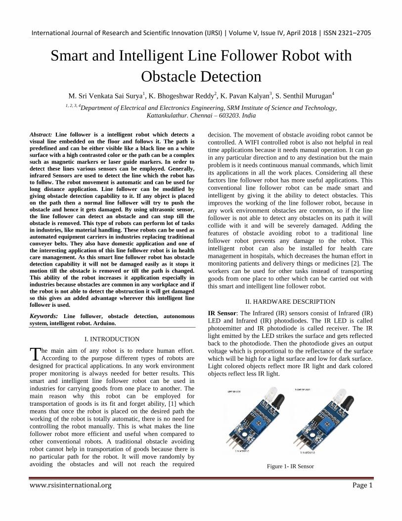
IR Sensor: The Infrared (IR) sensors consist of Infrared (IR)
LED and Infrared (IR) photodiodes. The IR LED is called
photoemitter and IR photodiode is called receiver. The IR
light emitted by the LED strikes the surface and gets reflected
back to the photodiode. Then the photodiode gives an output
voltage which is proportional to the reflectance of the surface
which will be high for a light surface and low for dark surface.
Light colored objects reflect more IR light and dark colored
objects reflect less IR light.
Figure 1- IR Sensor
T
International Journal of Research and Scientific Innovation (IJRSI) | Volume V, Issue IV, April 2018 | ISSN 2321–2705
www.rsisinternational.org Page 2
Ultrasonic Sensor: Ultrasonic sensor is a device which can
measure the distance to an object by using sound waves. It
will measure the distance by sending out a sound wave at a
particular frequency and listening that wave when it bounces
back. Ultrasonic sensor will not be able to detect some objects
because the reflected sound wave may deviate from its path
and will not be received by the ultrasonic sensor and so the
sensor cannot detect the obstacle. And also if the obstacle is
too small then the sound wave will not be able to bounce
back. Accuracy of the ultrasonic sensor also depends on the
temperature and humidity of the area where it is being used
but this factor can be neglected.[3]
Figure 2- Ultrasonic sensor
Arduino: To create devices which can interact with
environment using sensors and actuators the Arduino project
was started in 2003 aiming to provide a easy way for
professionals. Most of the Arduino boards consist of an Atmel
8-bit AVR microcontroller with varying amounts of flash
memory, pins and other features. Arduino boards are
programmed via Universal Serial Bus, implemented using
USB to Serial adapter chips such as FTDI FT232. A program
for Arduino can be written in any programming language with
compilers that produce binary machine code for the target
processor. The Arduino provides the integrated development
environment (IDE), which is a cross platform application
written in programming language JAVA. This IDE also
supports C and C++ using certain rules of code structuring.
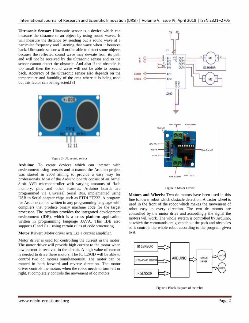
Motor Driver: Motor driver acts like a current amplifier.
Motor driver is used for controlling the current in the motor.
The motor driver will provide high current to the motor when
low current is received in the circuit. A high value of current
is needed to drive these motors. The IC L293D will be able to
control two dc motors simultaneously. The motor can be
rotated in both forward and reverse direction. The motor
driver controls the motors when the robot needs to turn left or
right. It completely controls the movement of dc motors.
Figure 3 Motor Driver
Motors and Wheels: Two dc motors have been used in this
line follower robot which obstacle detection. A castor wheel is
used in the front of the robot which makes the movement of
robot easy in every direction. The two dc motors are
controlled by the motor drive and accordingly the signal the
motors will work. The whole system is controlled by Arduino,
at which the commands are given about the path and obstacles
so it controls the whole robot according to the program given
to it.
Figure 4 Block diagram of the robot

International Journal of Research and Scientific Innovation (IJRSI) | Volume V, Issue IV, April 2018 | ISSN 2321–2705
www.rsisinternational.org Page 3
III. CODE
#include <NewPing.h> //Header Library for ultrasonic
sensor
int x,y,t1=0,t2=0; //Declaring variables
unsigned int D;
NewPing sonar(12,11,10); //Initializing ultrasonic sensor,
Syntax is NewPing sonar(TriggPin, EchoPin, Maxdistance);
void setup() {
pinMode(2,INPUT); //Initializing input pin of Infrared
sensor 1
pinMode(3,INPUT); //Initializing input pin of Infrared
sensor 2
pinMode(5,OUTPUT); //Initializing output pin 1 of motor
driver
pinMode(10,OUTPUT); //Initializing output pin 3 of motor
driver
pinMode(6,OUTPUT); //Initializing output pin 2 of motor
driver
pinMode(9,OUTPUT); } //Initializing output pin 4 of motor
driver
void loop() {
x=digitalRead(2); //Read value of Infrared sensor 1
y=digitalRead(3); //Read value of Infrared sensor 2
D=sonar.ping_cm(); //Check reading of ultrasonic sensor in
cm
if(D!=0) { //If ultrasonic sensor reads an obstruction in the
vicinity of max distance then stop robot
digitalWrite(5,LOW); //stop motors, stop moving
digitalWrite(10,LOW);
digitalWrite(6,LOW);
digitalWrite(9,LOW);
delay(1000);} //Delay of 1 second
else (D==0); {
if((x==1)&&(y==1)) { //If no IR sensor reads black line at
any side then move forward
digitalWrite(5,HIGH); //left motor clockwise
digitalWrite(10,HIGH); //right motor clockwise, moving
forward
digitalWrite(6,LOW);
digitalWrite(9,LOW);
t1=0;
t2=0; }
else if((x==1)&&(y==0)) { //If left IR sensor reads black
line then turn robot to right
if(t1>=20) {
digitalWrite(5,LOW); //If the robot is stuck while moving
right then move robot back for 0.5 seconds and move robot
right for 1 second
digitalWrite(10,LOW);
digitalWrite(6,HIGH); //left motor anticlockwise
digitalWrite(9,HIGH); //right motor anticlockwise, moving
backward when stuck
delay(500);
digitalWrite(5,HIGH); //left motor clockwise, turning right
digitalWrite(10,LOW);
digitalWrite(6,LOW);
digitalWrite(9,LOW);
delay(1000); }}
else {
digitalWrite(5,HIGH); //left motor clockwise, turning right
digitalWrite(10,LOW);
digitalWrite(6,LOW);
digitalWrite(9,LOW);
delay(500);
t1+=1; }
else if((x==0)&&(y==1)) { //If left IR sensor reads black
line then move the robot left
if(t2>=20) { //If the robot is stuck while moving left then
move robot back for 0.5 seconds and move robot left for 1
second.
digitalWrite(5,LOW);
digitalWrite(10,LOW);
digitalWrite(6,HIGH); //left motor anticlockwise
digitalWrite(9,HIGH); //right motor anticlockwise, moving
backward when stuck
delay(500);
digitalWrite(5,LOW);
digitalWrite(10,HIGH); //right motor clockwise, turning left
digitalWrite(6,LOW);
digitalWrite(9,LOW);
delay(1000); }}
else {
digitalWrite(5,LOW);
digitalWrite(10,HIGH); //right motor clockwise, turning left
digitalWrite(6,LOW);
digitalWrite(9,LOW);
delay(500);
t2+=1; } }
else if((x==0)&&(y==0)) { //If the two IR sensor reads
black line at both sides then the robot moves forward
digitalWrite(5,HIGH); //left motor clockwise
digitalWrite(10,HIGH); //right motor clockwise, moving
forward
digitalWrite(6,LOW);
digitalWrite(9,LOW);
t1=0;
t2=0; } }

International Journal of Research and Scientific Innovation (IJRSI) | Volume V, Issue IV, April 2018 | ISSN 2321–2705
www.rsisinternational.org Page 4
IV.WORKING PRINCIPLE
The ultrasonic sensor library has to be installed in Arduino
IDE. In the program the both the IR sensors have to
initialized. Four output pins of the motor have to be
initialized. Three variables have to be declared, two for both
the IR sensors and one for the ultrasonic sensor. [4] The two
variables which are declared for the IR sensor will read the
value of IR sensor1 and IR sensor2. The variable which is
declared for the ultrasonic sensor checks for any obstacle till a
mentioned distance. If the ultrasonic sensor detects any
obstacle in its path all the motors should stop, the four output
pins of the motor drive should be programmed as LOW,
which means they should stop working. So when an obstacle
is detected by the ultrasonic sensor then the motors will stop
and the robot will stop till the obstacle is removed from its
path. When no obstacle [5] and no black line is detected then
the robot should move forward.
Figure 5: Flow Chart of working of the robot
One pin on either side of the motor will be HIGH and the
other two pins will be LOW. This makes the left and right
motor to rotate in clockwise direction and hence the robot
moves forward. When only left IR sensor detects black line
then the robot has to turn left, for that only right motor has to
work. When the left motor stops and the right motor is
rotating in clockwise direction the robot will turn left. One pin
of the right motor should be HIGH and all the other pins
should be LOW. When only right IR sensor detects the black
line then the robot has to turn right, for that only left motor
has to work.
When the left motor stops and the right motor is rotating in
clockwise direction the robot will turn left. One pin of the left
motor should be HIGH and all the other pins should be LOW.
Figure 6: Forward movement
Figure 7: Stop the robot
When both the sensors are on white surface then the robot
moves forward and when both the sensors are on black
surface then the robot stops. In this case both the sensors will
detect the black line but the position where the sensors are
located decides whether the robot will stop or will move
forward.[6]
Figure 8: Turning left

International Journal of Research and Scientific Innovation (IJRSI) | Volume V, Issue IV, April 2018 | ISSN 2321–2705
www.rsisinternational.org Page 5
Figure 9: Turning right
When the left sensor detects the black line and right sensor is
not able to detect the black line then the robot has to turn left.
When the right sensor detects the black line and left sensor is
not able to detect the black line then the robot has to turn
right.
At any case if there is a black line then rotor has to stop.[7]
Figure 10: Complete block diagram of the designed robot
V FUTURE SCOPE
This smart and intelligent robot can be modified and
controlled using Bluetooth, WIFI module and other type of
sensors. The movement of the line follower can be controlled
either by using a Bluetooth or a WIFI module. By using any
of these modules, the line follower robot can be stopped, can
be turned right and can be turned left. This makes the line
follower robot more intelligent and useful. The line follower
cannot be stopped on its path if a Bluetooth or WIFI module is
not used. So to stop the robot without placing any other
obstacle this idea can be implemented to stop the robot or
even to change its path. One more idea which can be
implemented on the line follower is to make it a RGB color
following robot. The robot will be able to differentiate
between these three colors and according to the given
instruction it will follow the particular colored path. By using
this the path of the line follower can be modified in many
different ways making it easier to use it in different directions.
The robot will be able to detect three colors so the robot can
reach a particular position. This will not be possible by a
conventional line follower robot.
Figure 11: RGB with LDR
The RGB color detection sensor can be designed using a
Light Dependent Resistor(LDR) and three Light emitting
diodes namely red LED, green LED, and blue LED.[8] When
red light falls on a green and a red object, the red object will
reflect more light to the sensor than the green object to the
LDR sensor, so the color that will be detected by the LDR
sensor will be the red color.
VI HARDWARE RESULT
Left Motor Right Motor Robot Movement
Straight Straight Straight
Stop Straight Left
Straight Stop Right
Stop Stop Stop
Figure 12
Figure 13

International Journal of Research and Scientific Innovation (IJRSI) | Volume V, Issue IV, April 2018 | ISSN 2321–2705
www.rsisinternational.org Page 6
Figure 14: Smart and Intelligent Line Follower Robot
VII.CONCLUSION
The applications of the line follower are limited because it
cannot be controlled. The only way to control the line
follower is to change the path. Using WIFI module to control
the line follower robot will not be helpful because more power
will be consumed, so the battery will drain out quickly. Apart
from these limitations smart and intelligent line follower robot
can be used for long distance applications with a predefined
path.
This smart and intelligent robot has more benefits because it
doesn’t consume much power. This robotic system can
provide an alternative to the existing system by replacing
skilled labor, which in turn can perform better tasks with
accuracy and lower per capita cost.[9]
REFERENCES
[1]. Inteligent Line Follower Mini-Robot System Román Osorio C.,
José A. Romero, Mario Peña C., Ismael López-Juárez, International Journal of Computers, Communications & Control
Vol. I (2006), No. 2, pp. 73-83.
[2]. Development and Applications of Line Following Robot Based Health Care Management System by Deepak Punetha, Neeraj
Kumar, Vartika Mehta, International Journal of Advanced Research in Computer Engineering & Technology (IJARCET)
Volume 2, Issue 8, August 2013.
[3]. HCSR04 Ultrasonic Sensor Elijah J. Morgan Nov. 16 2014. [4]. SIMPLE DELIVERY ROBOT SYSTEM BASED ON LINE
MAPPING METHOD EndrowednesKuantama, Albert Brian
Lewis Lukas and Pono Budi Mardjoko Electrical Engineering, Universities PelitaHarapan, Jl. M.H. Thamrin Boulevard, Lippo
Karawaci, Tangerang Indonesia.
[5]. Obstacle Avoiding Robot By Faiza Tabassum, Susmita Lopa, Muhammad Masud Tarek & Dr. Bilkis Jamal Ferdosi, Global
Journal of Researches in Engineering.
[6]. Two Wheels Balancing Robot with Line Following Capability NorManiha Abdul Ghani, FaradilaNaim, Tan Piow Yon, World
Academy of Science, Engineering and Technology International
Journal of Mechanical and Mechatronics Engineering Vol:5, No:7, 2011.
[7]. OBSTACLE AVOIDING ROBOT – A PROMISING ONE
Rakesh Chandra Kumar1 , Md. Saddam Khan2 , Dinesh Kumar3 ,Rajesh Birua4 ,Sarmistha Mondal5 , ManasKr. Parai6
[8]. Design and implementation of RGB color line following robot
GADHVI SONAL PUNIT RANINGA HARDIK PATEL, Proceedings of the IEEE 2017 International Conference on
Computing Methodologies and Communication (ICCMC)
[9]. Colak, I., Yildirim, D.,"Evolving a Line Following Robot to use in shopping centers for entertainment”, Industrial Electronics, 2009.
IECON '09. 35th Annual Conference of IEEE,pp.3803 - 3807,3-5
Nov. 2009