smart energy innovator sumitomo electric
TRANSCRIPT
Redox Flow BatterySmart Energy InnovatorSumitomo Electric
01 02
Product Lineup
Container Type of Redox Flow Battery
Example of System Layout
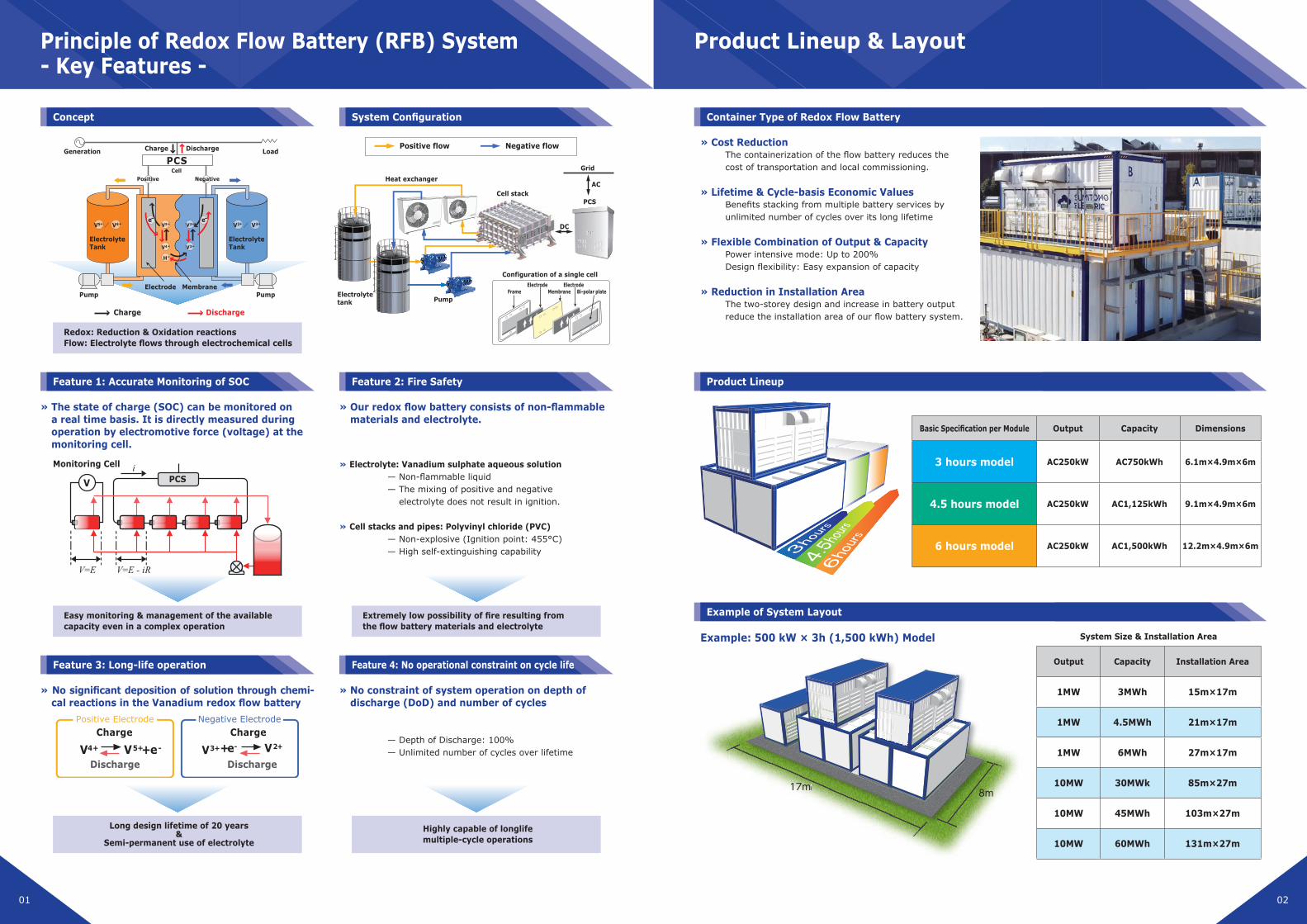
Concept
Feature 1: Accurate Monitoring of SOC
Feature 3: Long-life operation
System Configuration
Feature 2: Fire Safety
Feature 4: No operational constraint on cycle life
Principle of Redox Flow Battery (RFB) System- Key Features -
Product Lineup & Layout
» Cost Reduction The containerization of the flow battery reduces the cost of transportation and local commissioning.
» Lifetime & Cycle-basis Economic ValuesBenefits stacking from multiple battery services by unlimited number of cycles over its long lifetime
» Flexible Combination of Output & CapacityPower intensive mode: Up to 200% Design flexibility: Easy expansion of capacity
» Reduction in Installation AreaThe two-storey design and increase in battery output reduce the installation area of our flow battery system.
Example: 500 kW × 3h (1,500 kWh) Model
» The state of charge (SOC) can be monitored on a real time basis. It is directly measured during operation by electromotive force (voltage) at the monitoring cell.
» No significant deposition of solution through chemi-cal reactions in the Vanadium redox flow battery
» Our redox flow battery consists of non-flammable materials and electrolyte.
» No constraint of system operation on depth of discharge (DoD) and number of cycles
— Depth of Discharge: 100% — Unlimited number of cycles over lifetime
» Electrolyte: Vanadium sulphate aqueous solution — Non-flammable liquid — The mixing of positive and negative electrolyte does not result in ignition.
» Cell stacks and pipes: Polyvinyl chloride (PVC) — Non-explosive (Ignition point: 455°C) — High self-extinguishing capability
Easy monitoring & management of the available capacity even in a complex operation
Redox: Reduction & Oxidation reactionsFlow: Electrolyte flows through electrochemical cells
Long design lifetime of 20 years&
Semi-permanent use of electrolyte
Extremely low possibility of fire resulting from the flow battery materials and electrolyte
Highly capable of longlife multiple-cycle operations
Basic Specification per Module Output Capacity Dimensions
3 hours model AC250kW AC750kWh 6.1m×4.9m×6m
4.5 hours model AC250kW AC1,125kWh 9.1m×4.9m×6m
6 hours model AC250kW AC1,500kWh 12.2m×4.9m×6m
System Size & Installation Area
Output Capacity Installation Area
1MW 3MWh 15m×17m
1MW 4.5MWh 21m×17m
1MW 6MWh 27m×17m
10MW 30MWk 85m×27m
10MW 45MWh 103m×27m
10MW 60MWh 131m×27m
8m17m17m 8m
Positive flow Negative flow
Cell stackAC
DC
PCS
Heat exchangerGrid
Electrolytetank
Configuration of a single cell
PumpFrame
ElectrodeMembrane
ElectrodeBi-polar plate
ElectrolyteTank
Electrode Membrane
ElectrolyteTank
PCSCell
Charge Discharge
Charge Discharge
Positive Negative
LoadGeneration
V5+
H+
V4+
V2+
V3+
e- e-V5+ / V4+ V2+ / V3+
Pump Pump
V PCS
Monitoring Cell
Positive Electrode Negative Electrode
V4+ V +5 + e-
Charge
DischargeV3++ e- V2+
Charge
Discharge
03 04
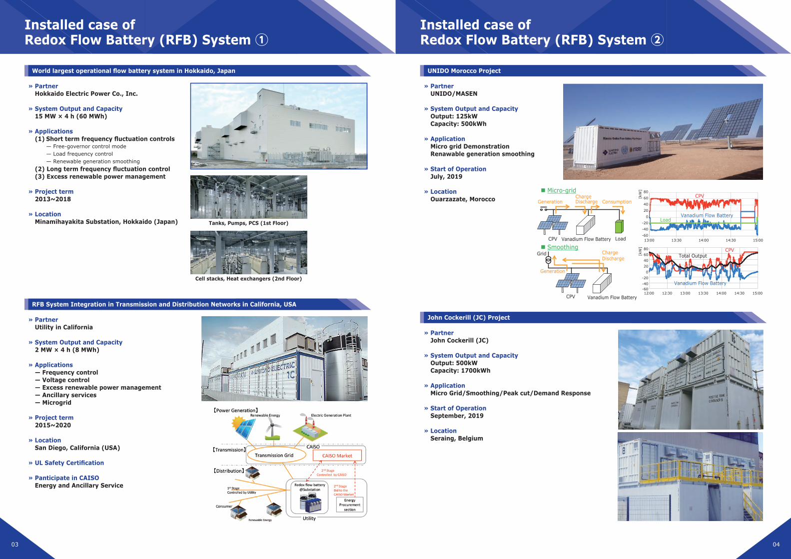
Vanadium Flow Battery
CPVTotal Output
Vanadium Flow Battery
CPV
Load
Micro-grid
CPV
Vanadium Flow Battery CPV Load
ConsumptionCharge Discharge Generation
Grid Smoothing
Generation
Charge Discharge
Vanadium Flow Battery
806040200
-20-40-60
15:0014:3014:0013:3013:0012:3012:00
13:00
80
60
40
20
-20
-40
-6013:30 14:00 14:30 15:00
0
[kW
][k
W]
UNIDO Morocco ProjectWorld largest operational flow battery system in Hokkaido, Japan
RFB System Integration in Transmission and Distribution Networks in California, USA
John Cockerill (JC) Project
Installed case of Redox Flow Battery (RFB) System ①
Installed case of Redox Flow Battery (RFB) System ②
» Partner Hokkaido Electric Power Co., Inc.
» System Output and Capacity 15 MW × 4 h (60 MWh)
» Applications (1) Short term frequency fluctuation controls
— Free-governor control mode — Load frequency control — Renewable generation smoothing
(2) Long term frequency fluctuation control (3) Excess renewable power management
» Project term 2013~2018
» Location Minamihayakita Substation, Hokkaido (Japan)
» Partner UNIDO/MASEN
» System Output and Capacity Output: 125kW Capacity: 500kWh
» Application Micro grid Demonstration Renawable generation smoothing
» Start of Operation July, 2019
» Location Ouarzazate, Morocco
» Partner John Cockerill (JC)
» System Output and Capacity Output: 500kW Capacity: 1700kWh
» Application Micro Grid/Smoothing/Peak cut/Demand Response
» Start of Operation September, 2019
» Location Seraing, Belgium
» Partner Utility in California
» System Output and Capacity 2 MW × 4 h (8 MWh)
» Applications — Frequency control — Voltage control — Excess renewable power management — Ancillary services — Microgrid
» Project term 2015~2020
» Location San Diego, California (USA)
» UL Safety Certification
» Panticipate in CAISO Energy and Ancillary Service
Cell stacks, Heat exchangers (2nd Floor)
Tanks, Pumps, PCS (1st Floor)
05 06
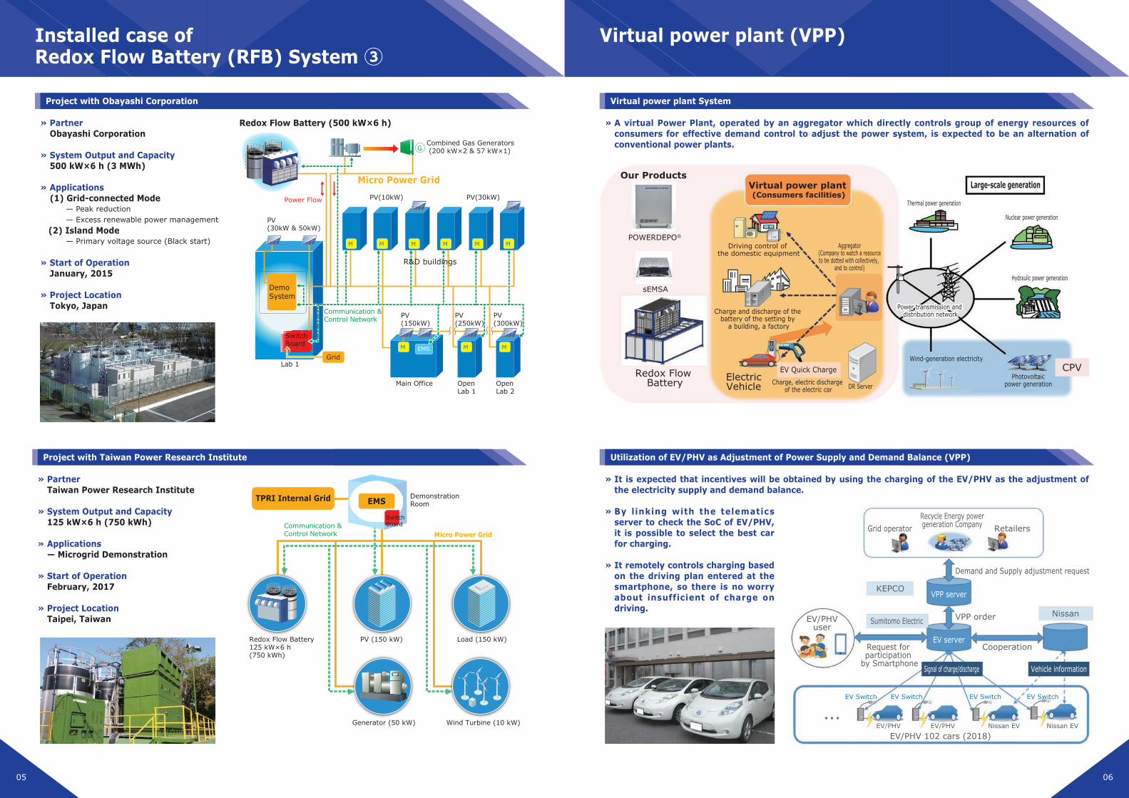
Virtual power plant System
Utilization of EV/PHV as Adjustment of Power Supply and Demand Balance (VPP)
Project with Obayashi Corporation
Project with Taiwan Power Research Institute
Installed case of Redox Flow Battery (RFB) System ③
Virtual power plant (VPP)
» Partner Obayashi Corporation
» System Output and Capacity 500 kW×6 h (3 MWh)
» Applications (1) Grid-connected Mode
— Peak reduction — Excess renewable power management
(2) Island Mode — Primary voltage source (Black start)
» Start of Operation January, 2015
» Project Location Tokyo, Japan
» A virtual Power Plant, operated by an aggregator which directly controls group of energy resources of consumers for effective demand control to adjust the power system, is expected to be an alternation of conventional power plants.
» It is expected that incentives will be obtained by using the charging of the EV/PHV as the adjustment of the electricity supply and demand balance.
» By linking with the telematics server to check the SoC of EV/PHV, it is possible to select the best car for charging.
» It remotely controls charging based on the driving plan entered at the smartphone, so there is no worry about insufficient of charge on driving.
» Partner Taiwan Power Research Institute
» System Output and Capacity 125 kW×6 h (750 kWh)
» Applications — Microgrid Demonstration
» Start of Operation February, 2017
» Project Location Taipei, Taiwan
Lab 1
Main Office Open Lab 1
Open Lab 2
Redox Flow Battery (500 kW×6 h)
Combined Gas Generators (200 kW×2 & 57 kW×1)
PV(30kW)
PV(300kW)
PV(250kW)
PV(150kW)
PV(30kW & 50kW)
PV(10kW)
Grid
Switch Board
R&D buildings
DemoSystem
Communication & Control Network
M EMS MM
MMMMMM
Power Flow
Micro Power Grid
G
EMSTPRI Internal Grid Demonstration Room
PV (150 kW) Load (150 kW)
Generator (50 kW)
Redox Flow Battery125 kW×6 h (750 kWh)
Wind Turbine (10 kW)
Switch Board
Micro Power GridCommunication & Control Network
POWERDEPO®
Driving control of the domestic equipment
Charge, electric discharge of the electric car
EV Quick Charge
Aggregator (Company to watch a resource to be dotted with collectively,
and to control)
Thermal power generation
Nuclear power generation
Hydraulic power generation
CPVElectricVehicle DR Server
Wind-generation electricity
Photovoltaicpower generation
Power transmission and distribution network
Power transmission and distribution networkCharge and discharge of the
battery of the setting by a building, a factory
sEMSA
Redox Flow Battery
Virtual power plant (Consumers facilities)
Large-scale generationOur Products
EV Switch EV Switch EV Switch EV Switch
EV/PHV EV/PHV
EV/PHV 102 cars (2018)
NissanSumitomo ElectricEV/PHV
user
Recycle Energy powergeneration Company
Request for participation
by Smartphone
Cooperation
VPP order
RetailersGrid operator
Demand and Supply adjustment request
KEPCO
Vehicle informationSignal of charge/discharge
EV server
VPP server
Nissan EV Nissan EV

Contact: Business Development Department, Energy System Division
Tel: +81 3 6406 2648 (Tokyo) +81 6 6466 5590 (Osaka)Address: 1-1-3, Shimaya, Konohana-ku, Osaka, JapanURL: https://global-sei.com/
Sumitomo Electric Industries, Ltd.
2020.02