smart pigs - university of houston–clear lake
TRANSCRIPT

www.tdwilliamson.com
® Registered trademarks of T.D. Williamson, Inc. in the United States and in other countries. © Copyright 2015
Smart Pigs
Adrian Belanger
March 7, 2017

2
Oil and Gas Pipeline Network

3
Pipeline Services

4
Why Pipeline Inspections?

5
Bellingham, WA - 1999

6
San Bruno, CA - 2010

7
What Are The Threats?

8
Threats - Overview
9
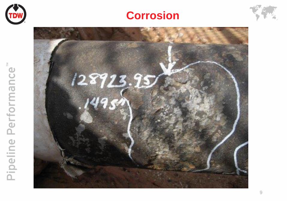
Corrosion

10
Selective Seam Corrosion

11
Cracking

12
Dent

13
Gouge
14
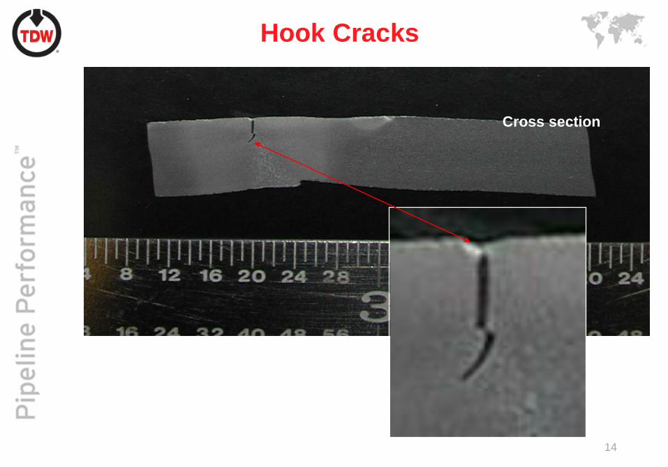
Hook Cracks
Cross section

15
Wrinkle Bend Failures

16
What Are The Solutions?

17
Magnetic Flux Leakage (MFL)
Changes in permeability cause magnetic lines of flux to “leak”
outside of the specimen, which can be measured by a sensor.

18
Low Field Magnetization

19
Permeability Tensor
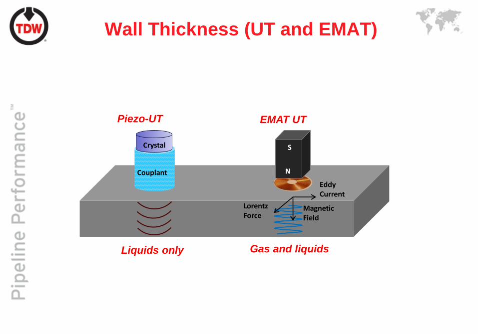
Liquids only Gas and liquids
Couplant
Crystal
N
S
LorentzForce
EddyCurrent
MagneticField
Piezo-UT EMAT UT
Wall Thickness (UT and EMAT)

• Applied magnetic field is parallel
to the current in the coil
• Alternating current generates a
magnetic field perpendicular to
the biasing field. This causes
magnetostriction
• The oscillating magnetostriction
generates a shear wave that
propagates in the direction of the
current
Magnetostrictive Lorentz
N
S
LorentzForce Magnetic
Field
SN
LorentzForce
MagneticField
EddyCurrent
Uses a magnetic biasing field and
pancake coil to create an acoustic
wave. When a pulsed high
frequency electric current is applied
to the transmitting coil, a time
varying magnetic field is induced
into the material. This field in turn
generates a pulse of elastic waves
into the pipe via the
magnetostrictive or Joule effect.
EddyCurrent
EMAT – Magnetostrictive vs. Lorentz

Guided Wave Modes
• Shear Horizontal
• Symmetric
• Anti-Symmetric

Pulse Echo Ultrasonic Inspection
• Transverse ultrasonic beams are oriented 90°to the surface of the
pipe.
• They detect the
reflection from the front
surface and the back
wall.
• This measurement is a
direct measurement of
wall thickness, though
in welds there is a lot of
scatter.
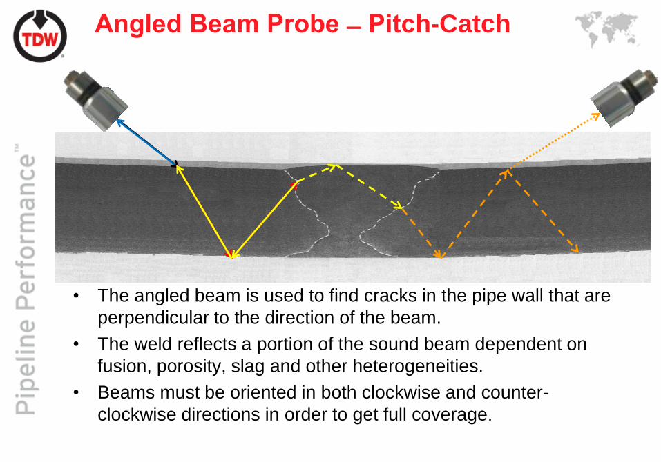
Angled Beam Probe ̶ Pitch-Catch
• The angled beam is used to find cracks in the pipe wall that are
perpendicular to the direction of the beam.
• The weld reflects a portion of the sound beam dependent on
fusion, porosity, slag and other heterogeneities.
• Beams must be oriented in both clockwise and counter-
clockwise directions in order to get full coverage.

Angled Beam Probe – Pulse Echo
• The maximum reflection is when a discontinuity is perpendicular
to the sound beam
• For a crack the maximum amount of signal is reflected by its
corner where it meets the surfaces
• Because the long seam can refract the UT signal, the sensor on
the crack side of the long seam has the best chance of detection

Eddy Current Testing

Impedance Plane

28
Inline Inspection Tools
(Smart Pigs)

MDS and EMAT
MDS
SMFL+MFL+LFM+DEF
EMAT
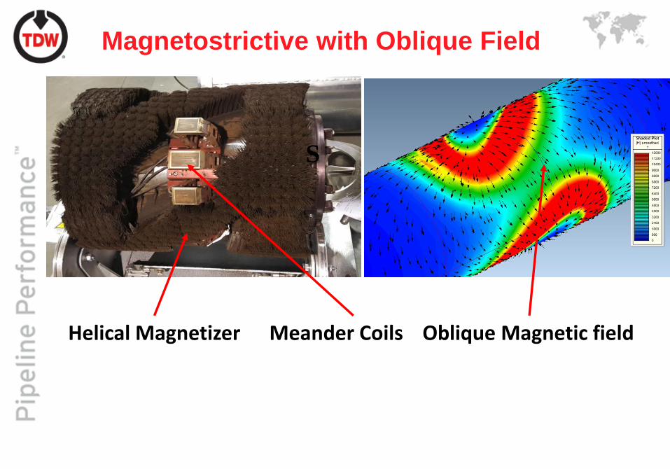
Meander Coils Oblique Magnetic fieldHelical Magnetizer
S
Magnetostrictive with Oblique Field

How Spiral Field Works
45° to 60° -
Magic
Angle
Range of optimum magnetization

EMAT Sensor Function
“Transmitting
pulse
Calibration receiver
(measures Direct
Transmission of signal
into pipe)
Normal attenuation
signal—no anomaly
Signal return due
to anomaly
Attenuation signal
minus return
Anomaly in pipe
Calibration receiver
(measures Direct
Transmission of signal
into pipe)

Propagation of Shear Horizontal Wave

34
Axial Magnetization
•The traditional method of magnetization is in the axial direction
as it is the easiest to design.
•North magnetic poles are placed at one end and South at the
other
Axial Direction
Solid Body – uses brushes to
introduce flux into the pipe wall.
Sled – Places magnetic bars
in close proximity to the pipe.

35
Spiral Magnetization
• Full circumferential
coverage with all sensors
in the sweet spot of the
magnetic field
• Magnetization at ~45
which can size axial
planar, circumferential
planar and pitting.
• Less dependent on tool
velocity.

36
MFL – Anomaly Orientation
Parallel
Parallel
Component
Radial
Component
Perpendicular
Component
Oblique
Parallel
Component
Radial
ComponentPerpendicular
Component
Perpendicular
Parallel Component
Radial Component Perpendicular
Component

37
Profilometry

38
MDS Data Results for HS - Overview

39
Hard Spot
Low FieldHigh Field Spiral Field

40
Sleeved Hard Spot with Crack
LFMMFL SMFL

41
Mechanical Damage

Future Work

Laser Profilometry Axial High Field
Aligning Data Sets
Axial Low Field Spiral Field

Strain
• Current standard sets a critical strain of 6%. This
standard is an empirical standard carried over from
ship manufacturing.
• Strain equations used by the industry use realistic
assumptions to make the calculations solvable and
repeatable.
• The greatest missing factor is the history of stress
application that caused the straining process.

Toughness
• Liquid lines are failing at pressures as low as 20%
specified minimum yield strength (SMYS)
• At present there are no inline solutions for measuring
toughness and the nondestructive evaluation (NDE)
techniques being used are still being validated.

Crack Propagation
• Crack Propagation depends strongly on material
properties like toughness that are hard to measure
nondestructively.
• Crack models make many assumptions and in light of
recent failures many of them are under review
• Data and algorithms for calculating failure are in most
part proprietary.
• A calculation that has a safety factor of 10 can
definitely use refinement.

Pipe Properties
• Because of all the mergers, acquisitions and lay-offs
over the last few decades, there are many lines with
missing or incomplete records.
• Operators have been operating under a grandfather
clause but new regulations from PHMSA are
requiring traceable, verifiable and complete
documentation for every joint of pipe.
• There are solutions being proposed for NDE and ILI.

NDE Techniques
Automatic Indenter Spectroscopy

Pipe Joint Classification
IDOD LFM
DEFMFL SMFL
Every data set
collected by the
multiple dataset
tool (MDS) can be
used to identify the
manufacture of that
joint

Conclusion
©2015-2017 KariaHerts56789
©2015-2017 KariaHearts56789