smart series ssm-15-11, ssm-15-12, ssm-30-12 ssa-15-11 ... · ee-000122-0003 rev: b d-m-e ssm/ssa...
TRANSCRIPT
EE-000122-0003 REV: B D-M-E SSM/SSA User’s Manual Page 1
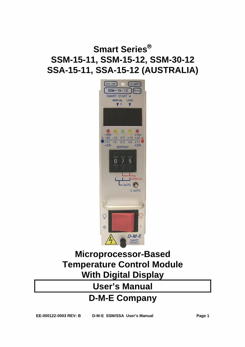
Smart Series SSM-15-11, SSM-15-12, SSM-30-12
SSA-15-11, SSA-15-12 (AUSTRALIA)
Microprocessor-Based Temperature Control Module
With Digital Display User’s Manual
D-M-E Company

EE-000122-0003 REV: B D-M-E SSM/SSA User’s Manual Page 2
Copyright D-M-E Company LLC 2010. All rights reserved. D-M-E Company products are covered by USA and foreign patents, trademarks and copyrights issued and pending. Information in this publication supersedes that in all previously published material. Specifications and any changes are reserved. Printed in the United States of America D-M-E Company LLC 29111 Stephenson Highway Madison Heights, MI 48071 USA D-M-E Company and D-M-E are registered trademarks of D-M-E Company LLC.
WARRANTY
D-M-E Company warrants that this product will be free from defects in materials and workmanship for a period of three (3) years from the date of shipment. If any such product proves defective during this warranty period, D-M-E Company, at its option, either will repair the defective product without charge for parts and labor, or will provide a replacement in exchange for the defective product. This warranty shall not apply to any defect, failure or damage caused by improper use or improper or inadequate maintenance and care. D-M-E Company shall not be obligated to furnish service under this warranty; a) to repair damage resulting from attempts by personnel other than D-M-E Company representatives to repair or service the product; b) to repair damage resulting from improper use or connection to incompatible equipment; or c) to service a product that has been modified or integrated with other products when the effect of such modification or integration increases the time or difficulty of servicing the product. This warranty excludes replacement of Fuses, Triac, Calibration, and damage to the product from the use of improper styles of fuses. ( Use only ABC type replacement F1 & F2 Load Fuses) The maximum allowable Load Fuse rating is 15 amps. Lower ratings may be used for improved protection.
SAFETY
D-M-E Company products have been designed to be safe and simple to operate. As with any electronic equipment, you must observe standard safety procedures to protect both yourself and the equipment. To Prevent Injuries: • To avoid electrical shock or fire hazard, do not apply voltage to a terminal that exceeds the
range specified for that terminal. • To avoid mechanical injury, electrical shock or fire hazard, do not operate this product with
covers or panels removed. All unused slots of a main frame must be covered with the appropriately sized blank panels.
• To avoid electrical shock or fire hazard, do not operate this product when wet. • To avoid injury or fire hazard, do not operate this product in an explosive atmosphere. To Prevent Product Damage: • Do not operate this product from a power source that applies more than the voltage specified.
EE-000122-0003 REV: B D-M-E SSM/SSA User’s Manual Page 3
GENERAL DESCRIPTION This Smart Series® module is a user-friendly temperature controller of world-class caliber. It is one of the most widely used controllers in the hot runner control industry. It has a large process temperature display, and it incorporates a 3-digit pushwheel for entering process temperature setpoints. The illuminated display shows process temperature in Auto, and Manual modes. Diagnostic fault codes for open (“OPE”), reversed (“bAC”), or shorted (“SHO”) thermocouples are displayed digitally. The module automatically inhibits output power to the heater load in Auto mode until such faults are corrected, unless the new “Automatic Bumpless Transfer” option is enabled. The modules LED display indicators (located at the top left of each digit) show the mode of operation. The power to heater “load” LED doubles as a Smart Start® indicator by blinking during Smart Start. Five separate color-coded LED's located under the display indicate temperature deviation and over/under temperature conditions at a glance.
OPERATION Auto Mode: The microprocessor maintains temperature using a proprietary closed loop control method. The microprocessor anticipates the heater load characteristics to make accurate adjustments and correct for errors. "Fuzzy logic" is used to minimize overshoot of setpoint on start-ups, and to prevent over and undershoots when changing setpoints. The SSM/SSA can also display the average percent output power when running in Auto mode. (“% Auto” setting) Smart Start ®: Smart Start® is automatic on start-up in Auto mode if the process temperature is below 212°F (100°C), and provides a linear power output ramp to ensure safe heater dry out. Smart Start® is completed after four minutes and thirty seconds has elapsed, or when process temperature exceeds the lesser of either the setpoint or 212°F (100°C) in Auto mode. Input Fault: Thermocouple break protection, and reversed thermocouple protection, override Smart Start® when in Auto mode. (Output power is inhibited) Shorted thermocouple protection, thermocouple break protection, and reversed thermocouple protection, inhibit output power in normal Auto mode operation. If a thermocouple fault occurs when the “Automatic Bumpless Transfer” feature is ON (after operating at setpoint temperature for >10 Minutes), the module will simulate manual mode using the average percent power learned during normal Auto operation.
Manual Mode: For no thermocouple, or a thermocouple failure, open loop percent output power is used. In Manual mode, the microprocessor maintains a power level using an open loop power control method. This enables the user to continue production, and override thermocouple faults until the problem has been resolved. Manual mode overrides thermocouple break protection, shorted thermocouple protection, reversed thermocouple protection, and any other normal automatic modes.
FEATURES ♦ Fully self-tuning, fuzzy logic, microprocessor-based
control. ♦ Selective Cycle and Smart Start® to prolong heater
life. ♦ New optional Smart Start heater-dry-out in Manual
mode. (Smart Start Override Disable) ♦ Zero crossing triac triggering for minimum Radio
Frequency Interference. (RFI) ♦ Process temperature display operational even in
Manual mode as long as the thermocouple (T/C) is intact.
♦ Automatic T/C fault protection and cold junction compensation.
♦ High impedance potentiometric input allows long distance T/C wiring.
♦ 100% solid-state circuitry, no mechanical relays. ♦ Completely self contained, no external output
devices or power supplies required. ♦ Fast acting heater load fuses are provided on both
sides of the AC line in 15 amp modules. (Except SSA) Circuit breakers are used in 30 amp modules.
♦ Electrically isolated, and grounded front panel for operator safety.
♦ Plug in design for module interchangeability. ♦ Alarm output capability and Standby Heat (Idle)
function with the DME TAS-05-02 module. ♦ Alarm output, Off, Standby Heat (Idle), and Boost
functions available with new TAS-05-12 module. ♦ New Auto Boost option for automatic temporary
raising of temperature at startup. (No additional module required)
♦ °F/°C configurable. ♦ J-type, or K-type thermocouple configurable. ♦ New Lights Out feature can be enabled to shut off
the digital LED display during stable Auto control. ♦ Adjustable response time to shorted thermocouple
faults. ♦ Compatible with all 10 and 15 amp G-Series®, and
Smart Series® Main Frames.
D-M-E Standard Smart Series Microprocessor-Based
Temperature Control Module With Digital Display SSM-15-11, SSM-15-12,
SSM-30-12, SSA-15-11, SSA-15-12 (AUSTRALIA)

EE-000122-0003 REV: B D-M-E SSM/SSA User’s Manual Page 4
PERFORMANCE SPECIFICATIONS Auto and Manual Control Modes: Selective Cycle: high speed time proportioning. Temperature Range: Ambient to 999°F (537°C) with J-type, and K-type thermocouples. Control Accuracy: +/-1°F (0.5°C), dependent on the total thermal system. Temperature Stability: +/-0.5% of full scale over the ambient range of 32 to 120°F. (0 to 50°C) Calibration Accuracy: Better than 0.2% of full scale. Power Response Time: Less than 0.13 seconds. Reset: Automatically corrects reset to no more than +/-1°F (1°C) at all settings. Manual Control: Adjustable from 0-99%. Maintains output power to within 1% of setting. Diagnostics Indicators: LED’s and 3-digit, 7-segment display. Smart Start ® (SS): Linear power output ramp from an initial temperature (< 212°F in Auto mode) to ensur e safe heater dry out. SS Duration: 4-1/2 minutes. SS Override Temperature: 212°F (100°C) Auto mode only. Operational Mode Priority: • Smart Start precedes Auto mode if process
temperature is < 212°F. • Thermocouple (T/C) break, or reversed T/C
overrides Auto mode Smart Start, and normal Auto mode.
• Shorted T/C overrides normal Auto mode. • Manual mode overrides T/C break, T/C open, and
reversed T/C. • The output is inhibited during all T/C fault conditions
in Auto mode unless Automatic Bumpless Transfer is enabled.
DIAGNOSTICS AND OTHER DISPLAY CODES (See figure 1) The SSM/SSA® diagnostics automatically alert the user to a fault condition. • Shorted thermocouple indicated by flashing SHO.
◊ Troubleshooting- Check for damage to the thermocouple lead wire. Also check for bare, twisted or pinched leads, open load fuse (F2, and/or F1), or excessive distance between the heater and thermocouple.
• Open thermocouple indicated by flashing OPE. ◊ Troubleshooting-
Check the thermocouple connections and wires for broken leads, check for damage to the sensor, or check for open fusible link resistor (R4, see figure 9)
• Reversed thermocouple indicated by flashing bAC. ◊ Troubleshooting-
Check thermocouple wiring for reversed leads. • Over/Under temperature. The red deviation LED on
the left, flashes when the process temperature is below setpoint by 40°F or more. The red deviation LED on the right flashes when the process is above setpoint by 40°F or more. ◊ Troubleshooting-
Under temperature; open heater, low line voltage, t/c problem, open load fuse (F2, and/or F1). Over temperature; output failure, shorted triac, interacting zones, heater shorted to ground.
• A remote signal ordering the module output off will cause a flashing OFF to be displayed.
• A remote signal ordering the module into standby heat (Idle) will cause a flashing SbH to be displayed.
• A remote signal ordering the module into boost heat will cause a flashing bSt to be displayed. Auto Boost will also display a flashing bSt.
• A flashing Loc is an indication that the Smart Start Override Disable option is ON, and that the module is in Smart Start. The Auto/Manual and Setpoint controls will be “locked out“ while this mode is active.
• A flashing Loc Err is an indication someone has changed the front panel settings prior to the completion of Smart Start when the Smart Start Override Disable option is ON. The Auto/Manual and Setpoint controls will be “locked out“ when the Loc Err diagnostic is active. ◊ Troubleshooting-
If the module is operating in Auto mode with a process temperature above 212°F (100°C), turn the module off, and change the settings back to their initial positions, then turn the module back on. The module will resume controlling to the entered setpoint. If the process temperature is below 212°F, (100°C) the module will restart the Smart Start process. If the module is operating in Manual mode, turn the module off, and change the settings back to their initial positions, then turn the module back
Figure 1 – Display
EE-000122-0003 REV: B D-M-E SSM/SSA User’s Manual Page 5
on. The module will restart the Smart Start process.
• A flashing bPL is an indication that the Automatic Bumpless Transfer option is ON, the thermocouple has failed, and the module has invoked an Automatic Bumpless Transfer. ◊ Troubleshooting-
Either shut down and repair the broken thermocouple, or: Press the AUTO% switch to display and record the average percent power value being output. Then place the module in Manual mode, and enter the percent power previously recorded.
INPUT SPECIFICATIONS Thermocouple (T/C) Sensor: Type "J" (default) or Type “K” (optional), grounded or ungrounded. External T/C Resistance: High impedance potentiometric input allows long distance T/C wiring. T/C Isolation: Isolated by control circuit power supply. Cold Junction Compensation: Automatic, better than 0.02°F/°F. (0.01°C/°C) Open T/C Protection: Automatically inhibits power to heater in Auto mode. (Unless Automatic Bumpless Transfer is enabled) Reversed T/C Protection: Automatically inhibits power to heater in Auto mode. (Unless Automatic Bumpless Transfer is enabled) Shorted T/C Protection: Automatically inhibits power to heater in Auto mode. (Unless Automatic Bumpless Transfer is enabled) Input Type: Potentiometric Input Impedance: 22 Meg ohms. Input Protection: Diode clamp, RC filter, and fusible link resistor R4. (See figure 9) Input Amplifier Stability: 0.02°F/°F (0.01°C/°C) Input Dynamic Range: 1000°F (537°C) with J-type, 1000°F (537°C) with K-type. Common Mode Rejection Ratio: Greater than 100 db. Power Supply Rejection Ratio: Greater than 90 db.
OUTPUT SPECIFICATIONS Voltage/Power Capability: 15 AMP: 120/240 VAC nominal, single-phase. SSM-15-11: 1800 watts @ 120 VAC SSM-15-12: 3600 watts @ 240 VAC SSA-15-11: 1800 watts @ 120 VAC SSA-15-12: 3600 watts @ 240 VAC 30 AMP: 240 VAC nominal, single-phase. SSM-30-12: 7200 watts @ 240 VAC Output Drive: Internal solid-state-triac, triggered by AC zero crossing pulses. Overload Protection: 15 AMP: Fuses are provided on both sides of AC line. (Except SSA) 30 AMP: Fast acting circuit breaker. Transient Protection: dv/dt and transient pulse suppression included. Power Line Isolation: Optically, and transformer isolated from AC lines. Isolation voltage is greater than 2500 volts.
ELECTRICAL POWER SPECIFICATIONS Supply Voltage: 120/240 VAC +10% -20% Frequency: 50/60 Hz DC Power Supplies: Internally generated, regulated and compensated. Module power usage: Less than 5 watts, excluding load. Dimensions: 15 AMP: 2"W x 7"H x 7 1/2"D (5.08 x 17.78 x 19.05cm) 30 AMP: 4"W x 7"H x 7 1/2"D (10.16 x 17.78 x 19.05cm) NOTE: Standard (240 VAC) modules are compatible with main frames wired for either 240 VAC three phase (standard) or 240 VAC single-phase. Use SSM/SSA-15-11 for 120VAC operation. Use SSM/SSA-15-12 for 240VAC operation. FUSE REQUIREMENTS: SSM-15: (2) ABC-15 cartridge fuses, F1 & F2 SSA-15: (1) ABC-15 cartridge fuse, F2 (Note: (2) spare ABC-15 fuses included with module) SSM/SSA: (1) 160 mA sub-miniature fuse, or 200 mA ceramic cartridge fuse, F3 (Check Module)
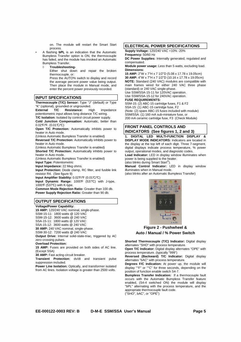
FRONT PANEL CONTROLS AND INDICATORS (See figures 1, 2 and 3) 1. DIGITAL LED MULTI-FUNCTION DISPLAY & DISPLAY MODE INDICATORS: Indicators are located in the display at the top left of each digit. Three 7-segment, digital displays indicate process temperature, % power output, operational modes, and diagnostic codes. Load Indicator: LED in display window illuminates when power is being supplied to the heater. (also blinks during Smart Start®). Manual Control Indicator: LED in display window illuminates when in Manual mode. (also blinks after an Automatic Bumpless Transfer)
Figure 2 - Pushwheel &
Auto / Manual / % Power Switch Shorted Thermocouple (T/C) Indicator: Digital display alternates "SHO" with process temperature. Open T/C Indicator: Digital display alternates "OPE" with process temperature. (typically "999") Reversed (Backward) T/C Indicator: Digital display alternates "bAC" with process temperature. Degrees F/C Indication: At power up, the module will display "°F" or "°C" for three seconds, depending on the position of function enable switch S4-7. Bumpless Transfer Indication: If a thermocouple fault occurs with the Automatic Bumpless Transfer feature enabled, (S4-4 switched ON) the module will display "bPL" alternating with the process temperature, and the appropriate thermocouple fault code. ("SHO", bAC", or "OPE")

EE-000122-0003 REV: B D-M-E SSM/SSA User’s Manual Page 6
Smart Start Override Disable: Digital display alternates "Loc" with process temperature during Smart Start if S4-2 is ON. The display will alternate “Loc” “Err” with process temperature after the completion of Smart Start, if the front panel settings were changed during Smart Start. Remote Off Signal: If switch S1-5 is ON and a remote power off signal is present, the module will display "OFF" alternating with process temperature. Remote Standby Heat Signal: If switch S4-1 is ON and a remote Standby Heat (Idle) signal is present, the module will display "SbH" alternating with process temperature. Remote Boost Signal or Autoboost: If the module is in a boost mode (S1-1,2,3,4), it will display "bSt" alternating with process temperature.
Figure 3 - SSM-15-12 Module
Note: The SSM-30-12 module is twice as wide as the SSM-15-12 and has a circuit breaker instead of item 5. 2. TEMPERATURE DEVIATION LIGHTS: Indicate amount of deviation from setpoint temperature. An outer Red light blinks when extreme over or under temperature condition greater than +/- 40°F (+/- 23°C) exists. Temperature Deviation Indicators: Five separate LED’s: > +/-20°F/11°C = (Red), > +/-10°F/5°C = (Yel low), 0°F/0°C = (Green) 3. SETPOINT / % POWER ADJUSTMENT: Three-digit pushwheel adjusts setpoint (Auto), or % power (Manual). Auto Setpoint Control Range: 0 to 999°F, 0 to 537°C. Resolution: 1°F (1°C) Manual (% Power) Control: Right two digits of three-digit pushwheel. Manual (% Power) Control Range: 0 to 99%. 4. AUTO / MANUAL / % AUTO SWITCH: Toggle switch, selects Auto, (setpoint temp.) or Manual (% power) control modes. Lower momentary position displays the percent power output in Auto mode, or percent power Automatic Bumpless Transfer value in the case of a thermocouple fault.
5. POWER ON / OFF SWITCH: Controls AC power to module. 16-amp rocker switch, UL, CSA, VDE approved. SSM-30-12 has a high-speed circuit breaker instead of the switch, UL, CSA, VDE approved.
FUNCTION ENABLE SWITCHES S1-1 Remote Boost Enable S1-2 Add 10% Boost S1-3 Add 20% Boost S1-4 Auto Boost Enable S1-5 Power Off Enable S1-6 Gain Cut (Normal/Fast Load) S4-1 Standby Heat Enable (Idle) S4-2 Smart Start (SS) Override Disable S4-3 Lights Out Enable S4-4 Auto Bumpless Enable S4-5 SHO Long S4-6 SHO Disable S4-7 Deg F/C
Figure 4 – Function Enable Switches
TEMPERATURE MODE °F / °C To operate the module in the °F (degrees Fahrenheit ) mode, place switch S4-7 in the OFF position. To operate the module in the °C (degrees Centigrade ) mode, place switch S4-7 in the ON position. (See figures 4 and 9) The mode of operation is displayed on startup as either "°F" or "°C".
AUTOMATIC BUMPLESS TRANSFER "Automatic Bumpless Transfer" is defined as a thermocouple failure causing the module to automatically switch into manual percent power mode, if the module has learned an average percent power. (The module requires approximately 10 minutes of stable temperature control to learn an average percent power) To enable Automatic Bumpless Transfer, place switch S4-4 in the ON position. To disable the Automatic Bumpless Transfer option, place switch S4-4 in the OFF position. If disabled, the power output will be inhibited after a thermocouple fault occurs. The user will then have to place the module in Manual mode to gain control of the output power. With an Automatic Bumpless Transfer active, the module will also enter an alarm state. The display will alternate between "bPL" ("bumpless"), the diagnostic code for the thermocouple fault, and the process temperature. If an alarm module is present, it will activate. To silence the alarm, push the AUTO% switch to view the average percent power being used, place the module in Manual mode and enter that percent power. With Automatic Bumpless disabled, the module will still learn the average percent power, but the user must press
1
3
5
2
4

EE-000122-0003 REV: B D-M-E SSM/SSA User’s Manual Page 7
the AUTO% switch, and record the average percent power prior to a thermocouple failure. Upon a thermocouple fault, the module will inhibit output power, and will enter an alarm state. The appropriate diagnostic code will alternate in the display with the process temperature. The user must then place the module in Manual mode and enter the recorded percent power. This action will clear the alarm.
LIGHTS OUT FEATURE The module can be programmed to shut off the digital LED display during stable Auto mode operation. This is beneficial with large systems (many zones of control) since it makes it easier to locate control zones with problems. To enable this option, set switch S4-3 to ON. After the module achieves stable operation about setpoint for 10 minutes, the digital LED display will turn off. Only the green deviation LED will be on. The display will turn back on automatically should an alarm condition occur, if any of the front panel switch settings are changed, if the process temperature deviates more than +/-10 °F in temperature, or if any remote modes of operation are active. It is recommended that the AUTO% switch be used to temporarily restore the display manually. The display will then turn off again after five minutes of stable operation about setpoint in Auto mode.
SMART START OVERRIDE DISABLE This Smart Start module incorporates an option to override the Smart Start feature in Auto mode by toggling the Auto/Manual switch to Manual and then back to Auto. By setting switch S4-2 to ON, this override can now be disabled. With switch S4-2 set to ON, the module will display "Loc" alternating with the process temperature during Smart Start. All front panel switch changes will be ignored during Smart Start. If the user changes any of the front panel settings during Smart Start, the module will continue to display "Loc" to indicate that the front panel is still "locked out". After Smart Start is complete, the module will check for front panel settings changes, and then display “Loc” “Err” alternating with the process temperature if any changes have occurred. Output power will still be active. If the module is operating in Auto mode with a process temperature above 212°F, (100°C) the user must turn the module off, and change the settings back to their initial positions, then turn the module back on. The module will resume controlling to the selected setpoint. If the process temperature is below 212°F, (100°C) the module will restart Smart Start. If the module is operating in Manual mode, turn the module off, and change the settings back to their initial positions, then turn the module back on. The module will restart the Smart Start process. Setting switch S4-2 to ON also activates a new Smart Start feature in Manual mode. With S4-2 ON, a module in Manual mode will ramp from zero percent to setpoint percent power over a 4-1/2 minute period, thus mimicking Smart Start in Auto mode. "Loc" will be displayed in this mode also. “Loc” “Err” will also be displayed afterward, if the user attempts changes to the front panel settings.
DESENSITIZING "SHO" Shorted Input override, SHO, is defined as a condition when the thermocouple is shorted and the module does not detect a rising temperature that corresponds to the output power being delivered. If the temperature rise does
not change at a rate of more than 2°F in 90 seconds , this is interpreted as a Shorted Input. Sometimes a 2-degree rise in 90 seconds is too sensitive. If this is the case, the module can be desensitized to this situation, or the diagnostic can be totally shut off. Switch S4-5 ("SHO Long") changes the sensitivity to 3 degrees in 255 seconds. Switch S4-6 ("SHO Disable") turns this diagnostic totally off. It is highly recommended that normal sensitivity be tried first. It should be sufficient for all nozzles and most manifolds. Large hot runner manifolds and molds may require desensitization. The SHO Disable feature should only be considered as a final resort.
REMOTE OFF When the DME TAS module (or similar mainframe option) initiates an OFF signal, any SSM/SSA module that has this feature enabled will alternate "OFF" with the process temperature, and will shut off power to their respective heaters.* To enable this option, switch S1-5 must be set to ON. This allows the user to select the modules in the system that will react to the OFF signal. * A communication style mainframe is required to support this feature.
Figure 5 - Side Panel
REMOTE STANDBY HEAT (Idle) When the DME TAS module (or similar mainframe option) initiates a Standby Heat (Idle) signal, any SSM/SSA module that has this feature enabled, and controlling in Auto mode, will immediately reduce the setpoint temperature to 212°F/100°C. If the module is controlling in Manual mode, the power output will be reduced to 3%. This function is useful for the continuous application of low power to heaters to prevent moisture build-up and initiate quick start-ups.* To enable this option, switch S4-1 must be set to ON. This allows the user to select the modules in the system that will react to the Standby Heat (Idle) signal. If a thermocouple failure occurs while in Standby Heat and Auto Bumpless is not enabled, the module will inhibit output power and will enter an alarm state. If a thermocouple failure occurs while in Standby Heat and Auto Bumpless is enabled, (after stable control for 10 minutes) the module will automatically switch to an average percentage of output power and enter an alarm state. To silence the alarm, push the AUTO% switch to view the average percent power being used, place the module in Manual and enter that percent power. * A communication style mainframe is required to support this feature.

EE-000122-0003 REV: B D-M-E SSM/SSA User’s Manual Page 8
REMOTE BOOST When the DME TAS module (or similar mainframe option) initiates a Boost signal, any SSM/SSA module that has this feature enabled, and controlling in Auto mode, will immediately increase the setpoint temperature according to the settings of switches S1-2 and S1-3. This function is useful for increasing temperature of nozzles for unblocking, or initial startup of the hot runner system.* If a thermocouple fails while in Boost, and Auto Bumpless is not enabled, the module will inhibit output power and will enter an alarm state. If a thermocouple failure occurs while in Boost and Auto Bumpless is enabled, (after stable control for 10 min’s) the module will automatically switch to an average percentage of output power and enter an alarm state. To silence the alarm, push the AUTO% switch to view the average percent power being used, place the module in Manual and enter that percent power. To enable this option, switch S1-1 must be set to ON and either or both switches S1-2 and S1-3 must be ON. This allows the user to select the modules in the system that will react to the Remote Boost signal. Switch S1-2 adds 10% to the entered setpoint. S1-3 adds 20% to the entered setpoint. Having both S1-2 and S1-3 ON adds 30% to the entered setpoint. For example; if S1-2 is ON, and the entered setpoint is 500 degrees, a remote boost input signal will cause the module to assume a 550 degree setpoint. Upon removal of the remote boost signal, the module will return to the 500 degree setpoint. * A communication style mainframe is required to support this feature.
AUTO BOOST Upon startup, any SSM/SSA module in Auto mode that has this feature enabled will increase the setpoint temperature according to the settings of switches S1-2 and S1-3 after the completion of Smart Start. This function is useful for increasing temperature of nozzles for initial startup of the hot runner system, but doesn't require an external signal. If a thermocouple fails during Auto Boost, the module will inhibit output power and will enter an alarm state. To enable this option, switch S1-4 must be set to ON, and either or both switches S1-2 and S1-3 must be ON. This allows the user to select the modules in the system that will react to Auto Boost. Switch S1-2 adds 10% to the entered setpoint. S1-3 adds 20% to the entered setpoint. Having both S1-2 and S1-3 ON adds 30% to the entered setpoint. For example; if S1-2 is ON and the entered setpoint is 500 degrees, power up will cause the module to assume a 550 degree setpoint for a period of 3 minutes after the completion of Smart Start. After 3 minutes, the module will return to the 500 degree setpoint. If also enabled, the presence of a Remote Boost signal will override Auto Boost. * * A communication style mainframe is required to support this feature.
GAIN ADJUSTMENT (Fast Load PID) If temperature oscillates during operation (Fast Load), the user can compensate for this by turning S1-6 to OFF. This is recommended for coil heaters with ungrounded internal thermocouples or very small nozzles.
ALARM OUTPUT When a DME TAS module is installed in the DME mainframe, this output feature will activate the alarm output on the TAS module. The TAS module will produce an audible alert, and provide a relay contact closure when a module alarm occurs. This alarm output feature is disabled upon power-up until the process temperature is within 10°F (5°C) of Setpoint temperature. It is al so disabled when changing setpoints manually, or remotely. Once the Setpoint temperature is reached, a deviation greater than +/-40°F (23°C) will activate the alarm output.* In Manual mode the alarm output will only activate due to a “Loc Err”. The user can silence a temperature deviation alarm by placing the module in Manual mode. * A communication style mainframe is required to support this feature.
K TYPE THERMOCOUPLE SELECT The SSM/SSA module can be converted for a K type thermocouple input by re-configuring the thermocouple type select jumpers. (see figures 6 and 9) Remove jumpers J5 and J6, and install jumpers J7, J8, and J21 for a K type thermocouple input. After converting the T/C to K type, or back to a J type, the module will require re-calibration.
CALIBRATION PROCEDURE – J OR K TYPE T/C (See figure 6 and 9) 1. Insert controller into the calibration fixture* and turn the power on. Wait 10-15 minutes for warm up. 2. Set the simulation temperature to 200°F (93°C) for J- type T/C. (400°F (204°C) for K-type T/C) 3. Adjust the ZERO trim pot, R13, to read 200°F (93°C) on the display for J-type T/C. (400°F (204°C) for K-type T/C) 4. Set the simulation temperature to 800°F (427°C) for J-type T/C. (650°F (343°C) for K-type T/C) 5. Adjust the GAIN trim pot, R18, to read 800°F (427°C) on the display for J-type T/C. (650°F (343°C) for K-type T/C) 6. Repeat steps 2 through 5 until no further trim pot adjustment is needed. 7. Turn power off and remove from calibration fixture *.
Figure 6 - Calibration Potentiometers
*The user can construct a calibration fixture from a DME MFP-1G (or MFHP-1G for 30 amp modules) mainframe and a thermocouple simulator/calibrator. (I.E. Omega model #CL25) A slot must be cut in the top of the main frame in order to access the calibration potentiometers.
EE-000122-0003 REV: B D-M-E SSM/SSA User’s Manual Page 9
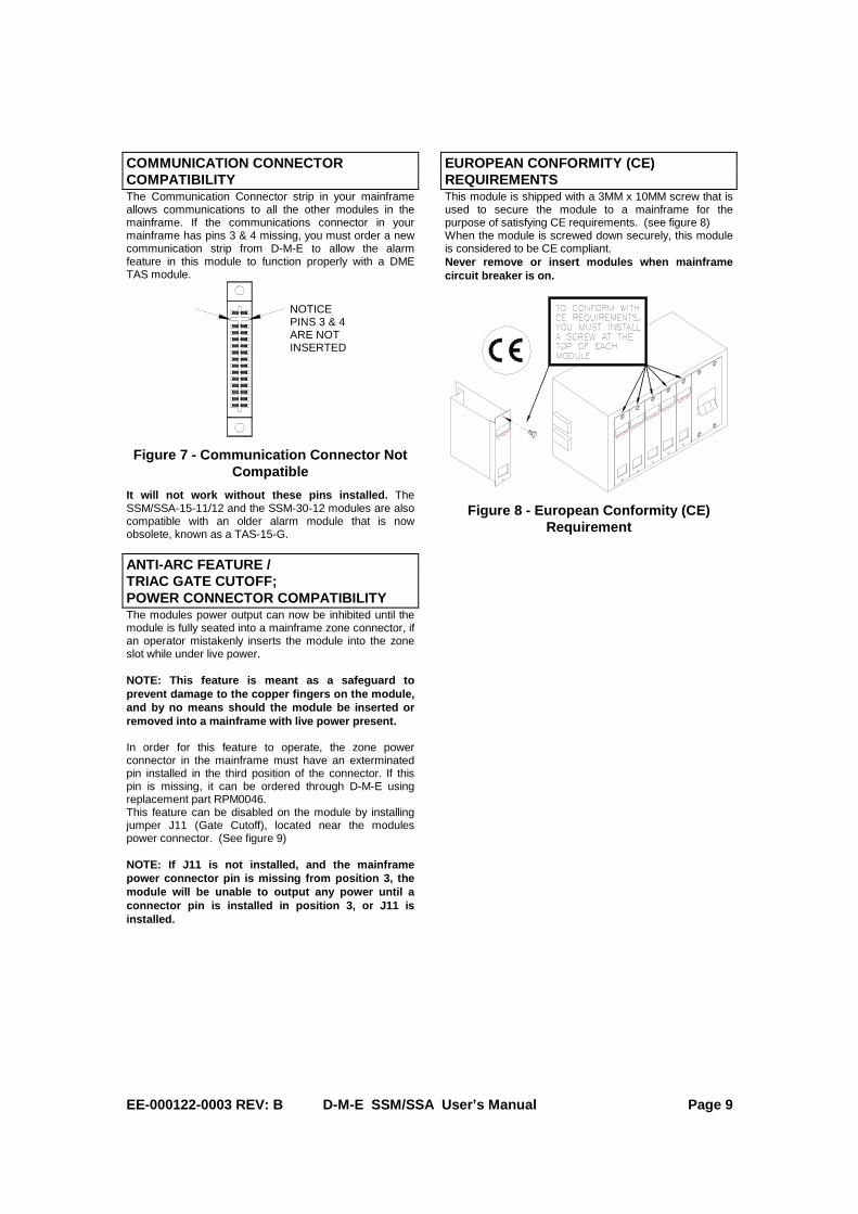
COMMUNICATION CONNECTOR COMPATIBILITY The Communication Connector strip in your mainframe allows communications to all the other modules in the mainframe. If the communications connector in your mainframe has pins 3 & 4 missing, you must order a new communication strip from D-M-E to allow the alarm feature in this module to function properly with a DME TAS module.
NOTICEPINS 3 & 4ARE NOTINSERTED
Figure 7 - Communication Connector Not Compatible
It will not work without these pins installed. The SSM/SSA-15-11/12 and the SSM-30-12 modules are also compatible with an older alarm module that is now obsolete, known as a TAS-15-G.
ANTI-ARC FEATURE / TRIAC GATE CUTOFF; POWER CONNECTOR COMPATIBILITY The modules power output can now be inhibited until the module is fully seated into a mainframe zone connector, if an operator mistakenly inserts the module into the zone slot while under live power. NOTE: This feature is meant as a safeguard to prevent damage to the copper fingers on the module, and by no means should the module be inserted or removed into a mainframe with live power present. In order for this feature to operate, the zone power connector in the mainframe must have an exterminated pin installed in the third position of the connector. If this pin is missing, it can be ordered through D-M-E using replacement part RPM0046. This feature can be disabled on the module by installing jumper J11 (Gate Cutoff), located near the modules power connector. (See figure 9) NOTE: If J11 is not installed, and the mainframe power connector pin is missing from position 3, the module will be unable to output any power until a connector pin is installed in position 3, or J11 is installed.
EUROPEAN CONFORMITY (CE) REQUIREMENTS This module is shipped with a 3MM x 10MM screw that is used to secure the module to a mainframe for the purpose of satisfying CE requirements. (see figure 8) When the module is screwed down securely, this module is considered to be CE compliant. Never remove or insert modules when mainframe circuit breaker is on.
Figure 8 - European Conformity (CE) Requirement
EE-000122-0003 REV: B D-M-E SSM/SSA User’s Manual Page 10
REPLACEMENT PARTS LIST
To meet warranty requirements, use only DME® parts. F1, F2, Fuse , 15 Amp, 250 Volt The use of lower amperage fuses for increased protection is recommended.
ABC15
Nylatch fastener, Plunger and Grommet NYL0001 Power Rocker Switch, 16 Amp, 250 VAC RPM0008 T1, Transformer, 240/120 Volt RPM0009 U5, Triac Driver RPM0010 Handle, 15 amp modules RPM0027 R4, Flameproof Fusible link resistor WARNING! DO NOT SUBSTITUTE
RPM0050
Setpoint pushwheel switch assembly, on front panel.
RPM0053
Q1, Triac, 40 Amp, 800 Volt RPM0054 S3, 3 position switch on front panel RPM0055 F3, Fuse , 160mA, 250 V, Sub-miniature (Check Module for correct fuse RPM#)
RPM0090
F3, Fuse , 200mA, 250 V, Cer. Cartridge (Check Module for correct fuse RPM#)
RPM0107
RETURN POLICY The D-M-E® SSM® and SSA modules are warranted for 3-years parts and labor, excluding fuses, triac, & calibration. Contact D-M-E Customer Service for return authorization for repairs, or warranties. Replacement parts are also available through the Customer Service Department. D-M-E Customer Service In U.S.: 1-800-626-6653 In Canada: 1-800-387-6600 SERVICE CENTER U.S.A. D-M-E WORLD HEADQUARTERS 29111 STEPHENSON HIGHWAY MADISON HEIGHTS, MICHIGAN 48071 Fax: (800) 461-9965 Internet: www.dme.net SSM®, G-Series®, Smart Series®, Smart Start®, and D-M-E® are all registered trademarks of D-M-E Company LLC. AUSTRALIA: Die Mould Equipment Pty. Ltd. ABN: 69 136 336 840 P.O. Box 1156, Unanderra, N.S.W. 2526, Australia Telephone: + 61 (0) 2 4272 3700 Fax: + 61 (0) 2 4271 3099 Internet: http://www.diemouldequipment.com.au/
EE-000122-0003 REV: B D-M-E SSM/SSA User’s Manual Page 11
FRONT PANEL CONTROLS & INDICATORS DIAGNOSTIC TEST P ROCEDURE

EE-000122-0003 REV: B D-M-E SSM/SSA User’s Manual Page 12
Figure 9 – SSM-15-12 Main Printed Circuit Board
COMMUNICATIONS CONNECTOR
FUSIBLE LINK
(RESISTOR R4) USE ONLY
FLAME-PROOF TYPE
DME #RPM0050
GATE CUTOFF DISABLE JUMPER
(J11)
FUSES F1, F2
(LOAD FUSES) DME #ABC15
*F2 ONLY FOR SSA/SHA*
FUSE F3 (PROTECTS
ELECTRONICS) DME #RPM0090 DME #RPM0107
CHECK MODULE FOR CORRECT
FUSE RPM#
TRANSFORMER 120/240 VOLTAGE
JUMPERS
FUNCTION ENABLE
SWITCHES
CALIBRATION POTENTIOMETERS
THERMOCOUPLE TYPE
JUMPERS
TRIAC DRIVER DME #RPM0010
AUTO/MANUAL/%PWR SWITCH (S3)
DME #RPM0055
POWER SWITCH DME #RPM0008
TRANSFORMER DME #RPM0009
PUSHWHEEL SWITCH DME #RPM0053