smart-ups™ vt rack mounted - - apc usa · 30–40 kva 400 v overview display interface the four...
TRANSCRIPT

Smart-UPS™ VT Rack Mounted30–40 kVA 400 V
Operation
06/2015
www.schneider-electric.com

Legal InformationThe Schneider Electric brand and any registered trademarks of Schneider ElectricIndustries SAS referred to in this guide are the sole property of Schneider ElectricSA and its subsidiaries. They may not be used for any purpose without the owner'spermission, given in writing. This guide and its content are protected, within themeaning of the French intellectual property code (Code de la propriétéintellectuelle français, referred to hereafter as "the Code"), under the laws ofcopyright covering texts, drawings and models, as well as by trademark law. Youagree not to reproduce, other than for your own personal, noncommercial use asdefined in the Code, all or part of this guide on any medium whatsoever withoutSchneider Electric's permission, given in writing. You also agree not to establishany hypertext links to this guide or its content. Schneider Electric does not grantany right or license for the personal and noncommercial use of the guide or itscontent, except for a non-exclusive license to consult it on an "as is" basis, at yourown risk. All other rights are reserved.
Electrical equipment should be installed, operated, serviced, and maintained onlyby qualified personnel. No responsibility is assumed by Schneider Electric for anyconsequences arising out of the use of this material.
As standards, specifications, and designs change from time to time, please ask forconfirmation of the information given in this publication.

30–40 kVA 400 V
Table of Contents
Important Safety Information.....................................................................5Safety Precautions .....................................................................................6Battery Safety ............................................................................................6
Overview ......................................................................................................8User Interface (Front)..................................................................................8User Interface (Rear) ..................................................................................9Display Interface.......................................................................................10
Operate the Display Interface...............................................................10Menu Tree ............................................................................................... 11
Operation ...................................................................................................13Operation Modes......................................................................................13
Normal Operation ...............................................................................13Battery Operation................................................................................13Static Bypass Operation ......................................................................13Internal Bypass Operation ..................................................................13External Maintenance Bypass Operation (Optional)...............................13
Operation Procedures...............................................................................14Turn into Internal Bypass Operation from Normal Operation ...................14Turn into Normal Operation from Internal Bypass Operation ...................15Perform a Total Power Off....................................................................15Perform a Restart ...............................................................................17Turn Load Off – Disconnect the UPS Output to the LoadEquipment..........................................................................................17Turn Load On – Connect the UPS Output to the Load Equipment ...........18Connect Load to the PDU....................................................................18View the Status Screens......................................................................22View Log ............................................................................................22View Statistics ....................................................................................23View Diagnostics ................................................................................23
Configuration .............................................................................................24Set the Clock............................................................................................24Set the Alarm Thresholds ..........................................................................25Change the Beeper Setup, the Contrast, and the Language.........................26
Beeper Setup .....................................................................................26Contrast .............................................................................................26Language...........................................................................................26
Maintenance ..............................................................................................27Parts Replacement ...................................................................................27
Determine if you need a Replacement Part ...........................................27Return Parts to Schneider Electric........................................................27User-Replaceable Parts (Only by Qualified Personnel) ..........................27Replace a Network Management Card .................................................28Replace a Battery Module....................................................................28
Troubleshooting ........................................................................................33Status and Alarm Messages......................................................................33
Display Messages...............................................................................33
990–2820B-001 3


Important Safety Information 30–40 kVA 400 V
Important Safety InformationRead these instructions carefully and look at the equipment to become familiar withit before trying to install, operate, service or maintain it. The following safetymessages may appear throughout this manual or on the equipment to warn ofpotential hazards or to call attention to information that clarifies or simplifies aprocedure.
The addition of this symbol to a “Danger” or “Warning” safetymessage indicates that an electrical hazard exists which will result inpersonal injury if the instructions are not followed.
This is the safety alert symbol. It is used to alert you to potentialpersonal injury hazards. Obey all safety messages with this symbolto avoid possible injury or death.
DANGERDANGER indicates a hazardous situation which, if not avoided, will result indeath or serious injury.
Failure to follow these instructions will result in death or serious injury.
WARNINGWARNING indicates a hazardous situation which, if not avoided, could result indeath or serious injury.
Failure to follow these instructions can result in death, serious injury, orequipment damage.
CAUTIONCAUTION indicates a hazardous situation which, if not avoided, could result inminor or moderate injury.
Failure to follow these instructions can result in injury or equipmentdamage.
NOTICENOTICE is used to address practices not related to physical injury. The safetyalert symbol shall not be used with this type of safety message.
Failure to follow these instructions can result in equipment damage.
Please NoteElectrical equipment should only be installed, operated, serviced, and maintainedby qualified personnel. No responsibility is assumed by Schneider Electric for anyconsequences arising out of the use of this material.
A qualified person is one who has skills and knowledge related to the construction,installation, and operation of electrical equipment and has received safety trainingto recognize and avoid the hazards involved.
990–2820B-001 5

30–40 kVA 400 V Important Safety Information
Safety Precautions
DANGERHAZARD OF ELECTRICAL SHOCK, EXPLOSION OR ARC FLASH
All safety instructions in this document must be read, understood and followed.
Failure to follow these instructions will result in death or serious injury.
DANGERHAZARD OF ELECTRICAL SHOCK, EXPLOSION OR ARC FLASH
After the UPS system has been electrically wired, do not start up the system.Startup must only be performed by Schneider Electric.
Failure to follow these instructions will result in death or serious injury.
Battery Safety
DANGERHAZARD OF ELECTRIC SHOCK, EXPLOSION OR ARC FLASH• Battery circuit breakers must be installed according to the specifications and
requirements as defined by Schneider Electric.
• Servicing of batteries must only be performed or supervised by qualifiedpersonnel knowledgeable of batteries and the required precautions. Keepunqualified personnel away from batteries.
• Disconnect charging source prior to connecting or disconnecting batteryterminals.
• Do not dispose of batteries in a fire as they can explode.
• Do not open, alter, or mutilate batteries. Released electrolyte is harmful to theskin and eyes. It may be toxic.
Failure to follow these instructions will result in death or serious injury.
DANGERHAZARD OF ELECTRIC SHOCK, EXPLOSION, OR ARC FLASH
Batteries can present a risk of electric shock and high short-circuit current. Thefollowing precautions must be observed when working on batteries
• Remove watches, rings, or other metal objects.
• Use tools with insulated handles.
• Wear protective glasses, gloves and boots.
• Do not lay tools or metal parts on top of batteries.
• Disconnect the charging source prior to connecting or disconnecting batteryterminals.
• Determine if the battery is inadvertently grounded. If inadvertently grounded,remove source from ground. Contact with any part of a grounded battery canresult in electric shock. The likelihood of such shock can be reduced if suchgrounds are removed during installation and maintenance (applicable toequipment and remote battery supplies not having a grounded supply circuit).
Failure to follow these instructions will result in death or serious injury.
6 990–2820B-001
Important Safety Information 30–40 kVA 400 V
DANGERHAZARD OF ELECTRIC SHOCK, EXPLOSION, OR ARC FLASH
When replacing batteries, always replace with the same type and number ofbatteries or battery packs.
Failure to follow these instructions will result in death or serious injury.
CAUTIONRISK OF EQUIPMENT DAMAGE• Wait until the system is ready to be powered up before installing batteries in
the system. The time duration from battery installation until the UPS systemis powered up must not exceed 72 hours or 3 days.
• Batteries must not be stored more than six months due to the requirement ofrecharging. If the UPS system remains de-energized for a long period, werecommend that you energize the UPS system for a period of 24 hours atleast once every month. This charges the batteries, thus avoiding irreversibledamage.
Failure to follow these instructions can result in injury or equipmentdamage.
990–2820B-001 7

30–40 kVA 400 V Overview
Overview
User Interface (Front)
Front View of the UPS Cabinet
A. Network management card with temperature sensor: Used for remote systemcontrol and monitoring, e-mail notifications, etc. For configuration and use, referto the separate network management card manual shipped with the UPS.
B. Computer-interface port for the connection of computers with Schneider ElectricPowerchute® software.
C. Internal mechanical bypass lever: Used to bypass the upstream utility/mainspower around the UPS to support the load directly = internal bypass operation.
D. Service port (for Schneider Electric maintenance personnel only).
E. Display port for the connection of display communication cable.
8 990–2820B-001

Overview 30–40 kVA 400 V
User Interface (Rear)The power distribution unit (PDU) is installed behind the rear doors of the UPS.
Rear View of the UPS Cabinet
990–2820B-001 9

30–40 kVA 400 V Overview
Display InterfaceThe four LEDs to the left of the display indicate the operational status of the UPS.The five navigation keys to the right are used to select and open menu items, toaccess information, change system parameters, and to get context-sensitive help.
A LOAD ON When the green LED is lit, the UPS provides power to the load equipment.
B ON BATT When the yellow LED is lit, power flows from the batteries to the load.
C BYPASS When the yellow LED is lit, power to the load is supplied through bypass.
D FAULT When the red LED is lit, a fault condition exists.
E LCD screen Displays alarms, status data, instructional help, and configuration items.
F Arrow keys Scrolls through and select menu items.
G Help key Opens context-sensitive help.
H Enter key Opens menu items and confirms changes to the system parameters.
I ESC key Returns to the previous screen displayed.
Operate the Display Interface
The Overview Screen is the main entrance to the user functions of the displayinterface. The arrow keys take you from one screen to another.
The Enter key takes you from the Overview Screen to the Main Screen.
From the Main Screen it is possible to command, configure, and monitor thesystem through the sub menu screens: Control, Status, Setup, LCM, Logging,Display, Diags, and Help (see the menu tree).The selector arrow (→) is controlledby the arrow keys. The selector arrow (→)marks the item you can open bypressing Enter key.
Overview Screen
Chrg xxx%Load xxx%xxxVin xxxVout xxHzRuntime: xxhr xxmin
10 990–2820B-001

Overview 30–40 kVA 400 V
Main Screen
→ Control LoggingStatus DisplaySetup DiagsLCM Help
Menu TreeNOTE: The display provides access to more functions than described in thismanual. Those functions should not be accessed without the assistance ofSchneider Electric Customer Support in order to avoid unwanted load impacts. Ifyou by accident go beyond the functions described, press ESC to return toprevious screens.
990–2820B-001 11

30–40 kVA 400 V Overview
The menu tree provides a quick overview of the functions and views you mayaccess.
Control Turn Load Off/OnUPS into/out of Bypass
Status Vin Vbyp Vout
lin lbyp lout
kW&kVAFrequencies Load
Load & Bat & Runtime Shutdown Runtime
Bat AmpHr/ UPS Temp Default
Alarm Thresholds System
Alarms
ClockOther
Setup Settings
LCM Alarms Pending
LCM Contact InfoLCM Alarm Settings
LCM Life Cycle Monitoring
Language
View Log Contrast
View Statistics Beep.Setup
Logging Logging Menu Display FW
Font PackDisplay Display Setup
Int.mech Byp. SW
Diags Faults and Diagnostics Q3 External Byp SW
System Information Status from MBP
Switch StatusRaw Status Data
On any screen and any line,press ? for context sensitive help
Help
12 990–2820B-001

Operation 30–40 kVA 400 V
Operation
Operation ModesThe UPS has different operation modes. If the installation includes an externalmaintenance bypass, external maintenance bypass operation mode will also beavailable.
Normal Operation
The UPS converts utility/mains power to conditioned power for the connected load.
Battery Operation
The UPS provides power to the connected load from its internal and (if available)external batteries for a finite period. The UPS transfers to battery operation if thesupply of utility/mains power fails, or is outside the pre-defined limits.
Static Bypass Operation
The UPS transfers to static bypass operation following a command on the displayor after a short or heavy overload on the output of the UPS, or if normal and batterymodes are unavailable. During static bypass operation the utility/mains power issent through internal radio frequency interference (RFI) filters to the load,bypassing the internal power converters. Battery back-up is not available in staticbypass operation even though the batteries are in place.
Internal Bypass Operation
Internal bypass keeps the load supplied with utility/mains power duringmaintenance of the UPS power sections. In internal bypass operation, utility/mainspower is sent directly to the connected load bypassing all internal UPS functionsand filters. Battery back-up is not available in internal bypass operation eventhough the batteries are in place.
External Maintenance Bypass Operation (Optional)
The UPS can be connected to an optional external maintenance bypass. Whenactivated, this panel bypasses the entire UPS cabinet, feeding utility/mains powerdirectly to the load. An activated external maintenance bypass completely isolatesthe UPS and allows maintenance to be performed.
990–2820B-001 13
30–40 kVA 400 V Operation
Operation Procedures
Turn into Internal Bypass Operation from Normal Operation
DANGERHAZARD OF ELECTRIC SHOCK, EXPLOSION OR ARC FLASH
In bypass operation the batteries are still powered. If a total power off is required,the load must be off, and the batteries must be pulled out to the red disconnectline.
Failure to follow these instructions will result in death or serious injury.
DANGERHAZARD OF ELECTRIC SHOCK, EXPLOSION OR ARC FLASH
The load is not protected by the UPS and the power is not conditioned when theinternal mechanical bypass lever is activated.
Failure to follow these instructions will result in death or serious injury.
1. If the UPS is running and controllable through the display, carry out steps 2-5. Ifnot, go directly to step 6.
2. From the Overview screen, press the Enter key.
3. Go to Control > UPS into Bypass by using the arrow keys and press the Enterkey.
→ UPS into BypassDo Self testSimulate Power FailStart Runtime Cal
4. Go to YES, UPS into Bypass by using the arrow keys and press the Enter key.
Confirm:UPS into BypassNO, ABORT
→ YES, UPS into Bypass
5. Check that the UPS is in bypass. The green (LOAD ON) and the yellow(BYPASS) LEDs are illuminated.
DANGERHAZARD OF ELECTRIC SHOCK, EXPLOSION OR ARC FLASH
For safety reasons, only qualified personnel is allowed to perform thefollowing steps.
Failure to follow these instructions will result in death or serious injury.
6. Remove the front panel from the UPS.
14 990–2820B-001

Operation 30–40 kVA 400 V
7. Turn the internal mechanical bypass lever upwards to activate it. The load willnow be supported directly by utility/mains power.
Turn into Normal Operation from Internal Bypass Operation
DANGERHAZARD OF ELECTRIC SHOCK, EXPLOSION, OR ARC FLASH
Never attempt to turn the UPS into normal operation till you have verified thatthere are no internal UPS faults.
Failure to follow these instructions will result in death or serious injury.
1. Check that the UPS is in bypass. The green (LOAD ON) and the yellow(BYPASS) LEDs are illuminated.
2. Turn the mechanical bypass lever downwards into a horizontal position todeactivate the internal bypass operation.
3. If the UPS has not returned to normal operation: Press the ESC key to return tothe previous menus and turn out of bypass from the display via Control > UPSout of bypass > Yes, UPS out of bypass.
4. Check that the UPS is in normal operation. The yellow BYPASS LED turns offand the green LOAD ON LED remains illuminated.
Perform a Total Power Off
NOTE: In order to carry out this procedure the load supported by the UPS must beturned off.
990–2820B-001 15

30–40 kVA 400 V Operation
A. Utility/mains breaker
B. UPS
C. Modular battery cabinet
1. Check that the load which is supported by the UPS is turned OFF.
2. From the UPS: Turn load OFF from the display viaControl > Turn Load Off > Yes, Turn Load Off.
3. From the modular battery cabinet(s) (if available): Set the DC disconnect switch(es) to position OFF.
4. From the UPS: Disconnect the batteries (if available) by pulling them out to thered disconnect line shown on each battery unit.
5. From the modular battery cabinet(s) (if available): Disconnect the batteries bypulling them out to the red disconnect line shown on each battery unit.
6. Set the utility/mains breaker to position OFF or LOCKED-OUT. If the UPS hasdual utility/mains supply, set both supplies to position OFF or LOCKED-OUT.
Post-requisite:
NOTE: The lockout procedures at the utility/mains breaker must be followed. Ifnecessary, install a padlock.
16 990–2820B-001

Operation 30–40 kVA 400 V
NOTE: For details on how to remove battery locks, see the section Replace aBattery Module, page 28 and hereunder Remove and Install Battery Locks, page30.
Perform a Restart
1. Set the utility/mains breaker to position ON.
2. If your installation includes a modular battery cabinet with a DC disconnectswitch, set the DC disconnect switch to position ON.
NOTE:Wait approximately 30 seconds for the system to boot up and carry outa self-test.
After system boot-up, the display will automatically ask you to confirm/selectvoltage and frequency as shown in the following.
3. When the Confirm Voltage prompt appears on the screen, go to the desiredvoltage using the arrow keys and press the Enter key.
4. When the prompt Apply load appears, go to Yes using the UP/DOWNnavigation keys and press the Enter key if you want the UPS to apply load tothe output now. (If you do not want a UPS load output at this point, go to No).
5. The green (LOAD ON) LED is now lit. Press the ESC key two times and thedisplay will return to the Overview Screen.
NOTE: The UPS is now ready to support the load.
NOTE: If the UPS system during a start-up detects an input frequency differentfrom what is already set, then the user will be asked to choose the detectedfrequency. The system will not change frequency by itself. For safety reasons,the input frequency can only be changed by the user. The auto-detection onfrequency-feature is only applicable in a single system start-up. If a problemoccurs call Schneider Electric.
Turn Load Off – Disconnect the UPS Output to the Load Equipment
DANGERHAZARD OF ELECTRIC SHOCK, EXPLOSION, OR ARC FLASH
Disconnecting the UPS output to the load does NOT de-energize the UPS.Always follow the Perform a Total Power Off, page 15 procedure if you need tode-energize the UPS.
Failure to follow these instructions will result in death or serious injury.
1. From the Overview Screen, press the Enter key.
2. Go to Control > Turn Load OFF > YES, Turn Load OFF by using the arrowkeys and press the Enter key.
Confirm:Turn Load OFFNO, ABORT
→ YES, Turn Load OFF
990–2820B-001 17

30–40 kVA 400 V Operation
Turn Load On – Connect the UPS Output to the Load Equipment
1. From the Overview Screen, press the Enter key.
2. Go to Control > Turn Load ON > Yes, Turn Load ON by using the arrow keysand press the Enter key.
Confirm:Turn Load OFFNO, ABORT
→ YES, Turn Load ON
Connect Load to the PDU
NOTE: Share the load evenly between the 3 phases to avoid overloading oneparticular single phase. The total output capacity of the PDU is approximately twicethe output capability of the UPS, meaning that the UPS would be over-loaded if alloutlets were loaded to their rating. Load status on the individual phases can befound through the UPS display or through the web interface.
NOTE: Equipment connected to the 3-phased output can require overcurrentprotection with a lower rating than the 3-phased output.
NOTE: For 3-phased outputs, the highest current is in the neutral conductor atnon-linear loads (up to 173%).
PDU Output Breaker Ratings
16 32 40 50
Rear of unit Ambienttemperature infront of unit °C
Nominal Breaker Rating
Free exhaust 20 16 32 40 50
Free exhaust 30 14.4 30.4 38 47.5
Free exhaust 40 12.8 27.2 34 42.5
Hot aislecontainment
25 14.4 30.4 38 47.5
18 990–2820B-001

Operation 30–40 kVA 400 V
Connect 1–Phase Load to PDU I
1. Set the applicable breaker to the OFF position.
2. Guide the load cable down through the top hole.
3. Insert the plug from the load into the C19 outlet.
4. Secure the plug by inserting the locking brackets.
5. Set the applicable breaker to the ON position.
990–2820B-001 19

30–40 kVA 400 V Operation
Connect 1–Phase Load to PDU II
1. Set the applicable breaker to the OFF position.
2. Guide the load cable down through the top hole.
3. Lift up the receptacle cover and connect the load to the CEE 16 A outlet.
4. Reset the breaker to the ON position.
20 990–2820B-001

Operation 30–40 kVA 400 V
Connect 3–Phase Load to PDU II
1. Set the applicable breaker to the OFF position.
2. Guide the load cable down through the top hole.
3. Lift up the receptacle cover and connect the load to the CEE 32 A outlet.
4. Set the breaker to the ON position.
Disconnect the Load from the PDUs
1. Set the applicable breakers to the OFF position.
990–2820B-001 21

30–40 kVA 400 V Operation
View the Status Screens
1. From the Overview Screen, press the Enter key.
2. Go to Status by using the arrow keys and press the Enter key.
Control Logging→ Status Display
Setup DiagsLCM Help
3. Use the arrow keys to go through the below parameters and press the ESC keyto return to the previous menus.
Status parameters Description
Voltage on all phases Utility/mains voltage (V), bypass voltage (V), andoutput voltage (V) for each phase.
Current on all phases Utility/mains current (A), bypass current (A), andoutput current (A) for each phase.
kVA and kW Apparent power (kVA) and real power (kW) generatedby the UPS and the connected load.
Frequencies Utility/mains frequency, bypass frequency, and outputfrequency in Hertz (Hz).
Load and batteries Load: Percentage of the load in relation to the totalUPS capacity.
Bat Voltage Shows either the positive or negative half of thebattery voltage (the lower value of the two will appear).
Bat Cap Percentage charge on the batteries in relation to thetotal battery capacity.Runtime: The predicted runtime at the present load.
Batteries Bat AmpHr: Battery capacity, including both externaland internal batteries.UPS Temp: The highest external battery temperature.
Alarm thresholds Load: An alarm will be set when the load is above thethreshold level.Runtime: An alarm will be set when the runtime isbelow the threshold level.
View Log
1. From the Overview Screen, press the Enter key.
2. Go to Logging > View Log > On Line by using the arrow keys and press theEnter key. Here you can see the 100 most recent UPS log events, and thelogged details of the events, such as date, time of occurrence, and eventnumber.
24-Sep 15:06:48 #15Mains out of Range
→ On Line
The top line states date, time, and event number. Lines 2, 3, and 4 are part ofthe event list. To view the entire list: Use the arrow keys to go through the logevents and press the Enter key to get a detailed description of a particularevent.
22 990–2820B-001

Operation 30–40 kVA 400 V
View Statistics
1. From the Overview Screen, press the Enter key.
2. Go to Logging > View Statistics by using the arrow keys and press the Enterkey. Here you can see statistics on the operation mode changes, the invertertime, and the duration of battery operation.
View logClear log
→ View statistics
View Diagnostics
1. From the Overview Screen, press the Enter key.
2. Go to Diags > Fault & Diagnostics by using the arrow keys and press theEnter key. Here you can see information given on alarms for use introubleshooting.
→ Fault & DiagnosticsSystem InformationSwitch statusRaw Status Data
NOTE: For more details on the Fault and Diagnostics screens, see thetroubleshooting section .
990–2820B-001 23

30–40 kVA 400 V Configuration
Configuration
Set the ClockThe Clockmenu changes the date and the clock settings and it time-stampsevents in the event log. To avoid inaccuracies, change the clock-setting at daylight-saving time.
1. From the Overview Screen, press the Enter key.
2. Go to Setup > Clock by using the arrow keys and press the Enter key.
Settings:Shutdown AlarmsDefault → ClockSystem Other
3. Press the Enter key.
→ Date: 24-Sep-2010Time: 13:45:51
4. The day is now active. Use the arrow keys to set the date and press the Enterkey.
→ Date: 24-Sep-2010Time: 13:28:00
5. The month is now active. Use the arrow keys to set the month, press the Enterkey and do the same to set the year, and press the Enter key.
→ Date: 24-Sep-2010Time: 13:28:00
6. Press the DOWN arrow key to activate the Time line.
Date: 24-Sep-2010→ Time: 13:28:00
The procedure to change the Time features is the same as described for date,month, and year.
7. Press the ESC key when you want to exit this menu.
24 990–2820B-001

Configuration 30–40 kVA 400 V
Set the Alarm ThresholdsNOTE: If the load level exceeds the preprogrammed threshold, the UPS willdisplay a warning.
1. From the Overview Screen, press the Enter key.
2. Go to Setup > Alarms by using the arrow keys and press the Enter key.
Settings:Shutdown → AlarmsDefault ClockSystem Other
3. Press the Enter key to activate the first threshold and use the arrow keys to setthe threshold. Press the Enter key to confirm.
Alarm thresholds→ Load: 20.0 kVA
Runtime: 0 hr 0 min
4. Press the Enter key to activate the second threshold and use the arrow keys toset the threshold. Press the Enter key to confirm.
Alarm thresholdsLoad: 20.0 kVA
→ Runtime: 0 hr 0 min
5. Press the ESC key when you want to exit this menu.
990–2820B-001 25

30–40 kVA 400 V Configuration
Change the Beeper Setup, the Contrast, and the Language
Beeper Setup
Select Display > Display Setup > Beeper setup and use the arrow keys and theEnter key to set the beeper settings.
• Never: If you select this setting, the beeper will be active at internal UPS errorsonly.
• PwrFail+30: If you select this setting, the beeper will be active at internal UPSerrors and at utility/mains or bypass errors. The beeper will only sound if thefault has been present for more than 30 seconds.
• PwrFail: If you select this setting, the beeper will be active at internal UPSerrors and at utility/mains or bypass errors. The beeper will sound immediatelywhen the error is occurring.
• LOW BATT: If you select this setting, the beeper will be active at internal UPSerrors at utility/mains or bypass errors, at power failures, and at a low batterylevel (if the UPS runs in battery operation).
Contrast
Select Display > Display Setup > Contrast and use the arrow keys and the Enterkey to select the contrast level. The lower the value, the darker the contrast.
Language
Select Display > Display Setup > Language and use the arrow keys and theEnter key to select the language.
26 990–2820B-001

Maintenance 30–40 kVA 400 V
Maintenance
Parts Replacement
Determine if you need a Replacement Part
To determine if you need a replacement part, contact Schneider Electric and followthe procedure below so that the representative can assist you promptly:
1. In the event of an alarm condition, scroll through the alarm lists, record theinformation, and provide it to the representative.
2. Write down the serial number of the unit so that you will have it easilyaccessible when you contact Schneider Electric.
3. If possible, call Schneider Electric from a telephone that is within reach of thedisplay so that you can gather and report additional information to therepresentative.
4. Be prepared to provide a detailed description of the problem. A representativewill help you solve the problem over the telephone, if possible, or will assign areturn material authorization (RMA) number to you. If a module is returned toSchneider Electric, this RMA number must be clearly printed on the outside ofthe package.
5. If the unit is within the warranty period and has been started up by SchneiderElectric, repairs or replacements will be performed free of charge. If it is notwithin the warranty period, there will be a charge.
6. If the unit is covered by a Schneider Electric service contract, have the contractavailable to provide information to the representative.
Return Parts to Schneider Electric
Call Schneider Electric to obtain an RMA number.
To return an inoperable part to Schneider Electric, pack the module in the originalshipping materials, and return it by insured, prepaid carrier. The customer supportrepresentative will provide the destination address. If you no longer have theoriginal shipping materials, ask the representative about obtaining a new set. Packthe module properly to avoid damage in transit. Never use styrofoam beads orother loose packaging materials when shipping a module. The module may settlein transit and become damaged. Enclose a letter in the package with your name,RMA number, address, a copy of the sales receipt, description of the problem, aphone number, and a confirmation for payment (if necessary).
NOTE: Damages sustained in transit are not covered under warranty.
User-Replaceable Parts (Only by Qualified Personnel)
Parts Part Number
Battery module SYBT4
Network management card with temperaturesensor
AP9631
Temperature/humidity sensor AP9512THBLK
990–2820B-001 27

30–40 kVA 400 V Maintenance
Replace a Network Management Card
10/100Base-TProbe
AP9619 Network Management Card EM
!
Reset
Output Pwr Zone
10/100
������ ������
1. Loosen the two Torx screws (one on each side of the card).
2. Carefully pull out the card.
3. Install the new card.
4. Reattach the two Torx screws.
Replace a Battery Module
NOTE: Use two people to lift components weighing between 18–32 kg (40–70 lb).
DANGERHAZARD OF ELECTRIC SHOCK, EXPLOSION OR ARC FLASH• Servicing of batteries must only be performed or supervised by qualified
personnel knowledgeable of batteries and the required precautions. Keepunqualified personnel away from batteries.
• Disconnect charging source prior to connecting or disconnecting batteryterminals.
• Do not dispose of batteries in a fire as they can explode.
• Do not open, alter, or mutilate batteries. Released electrolyte is harmful to theskin and eyes. It may be toxic.
Failure to follow these instructions will result in death or serious injury.
DANGERHAZARD OF ELECTRIC SHOCK, EXPLOSION, OR ARC FLASH
Batteries can present a risk of electric shock and high short-circuit current. Thefollowing precautions must be observed when working on batteries
• Remove watches, rings, or other metal objects.
• Use tools with insulated handles.
• Wear protective glasses, gloves and boots.
• Do not lay tools or metal parts on top of batteries.
• Disconnect the charging source prior to connecting or disconnecting batteryterminals.
• Determine if the battery is inadvertently grounded. If inadvertently grounded,remove source from ground. Contact with any part of a grounded battery canresult in electric shock. The likelihood of such shock can be reduced if suchgrounds are removed during installation and maintenance (applicable toequipment and remote battery supplies not having a grounded supply circuit).
Failure to follow these instructions will result in death or serious injury.
28 990–2820B-001

Maintenance 30–40 kVA 400 V
DANGERHAZARD OF ELECTRIC SHOCK, EXPLOSION, OR ARC FLASH
When replacing batteries, always replace with the same type and number ofbatteries or battery packs.
Failure to follow these instructions will result in death or serious injury.
Store the Batteries and the UPS System
NOTE: The battery modules must be stored indoors and with their protectivepackaging still in place.
NOTE: Stored batteries should be recharged at regular intervals, depending onthe storage temperature.
Ambient temperature:-15 to 40 °C/5 to 104 °F
Relative Humidity:0-95% Non-condensing
Storage place free fromvibration, conductive dust,direct sunlight, and moisture.
Storage Temperature Recharge Interval
-15 to 20 °C/5 to 68 °F
9 months
20 to 30 °C/68 to 86 °F
6 months
30 to 40 °C/86 to 104 °F
3 months
CAUTIONRISK OF EQUIPMENT DAMAGE• Wait until the system is ready to be powered up before installing batteries in
the system. The time duration from battery installation until the UPS systemis powered up must not exceed 72 hours or 3 days.
• Batteries must not be stored more than six months due to the requirement ofrecharging. If the UPS system remains de-energized for a long period, werecommend that you energize the UPS system for a period of 24 hours atleast once every month. This charges the batteries, thus avoiding irreversibledamage.
Failure to follow these instructions can result in injury or equipmentdamage.
Battery Module
One battery module consists of four battery units (shipped in the cabinets).
Model:
Serial:
BATTERY UNIT
Model:
Serial:
BATTERY UNIT
Model:
Serial:
BATTERY UNIT
Model:
Serial:
BATTERY UNIT
990–2820B-001 29
30–40 kVA 400 V Maintenance
4 x 24 kg/4 x 53 lbs
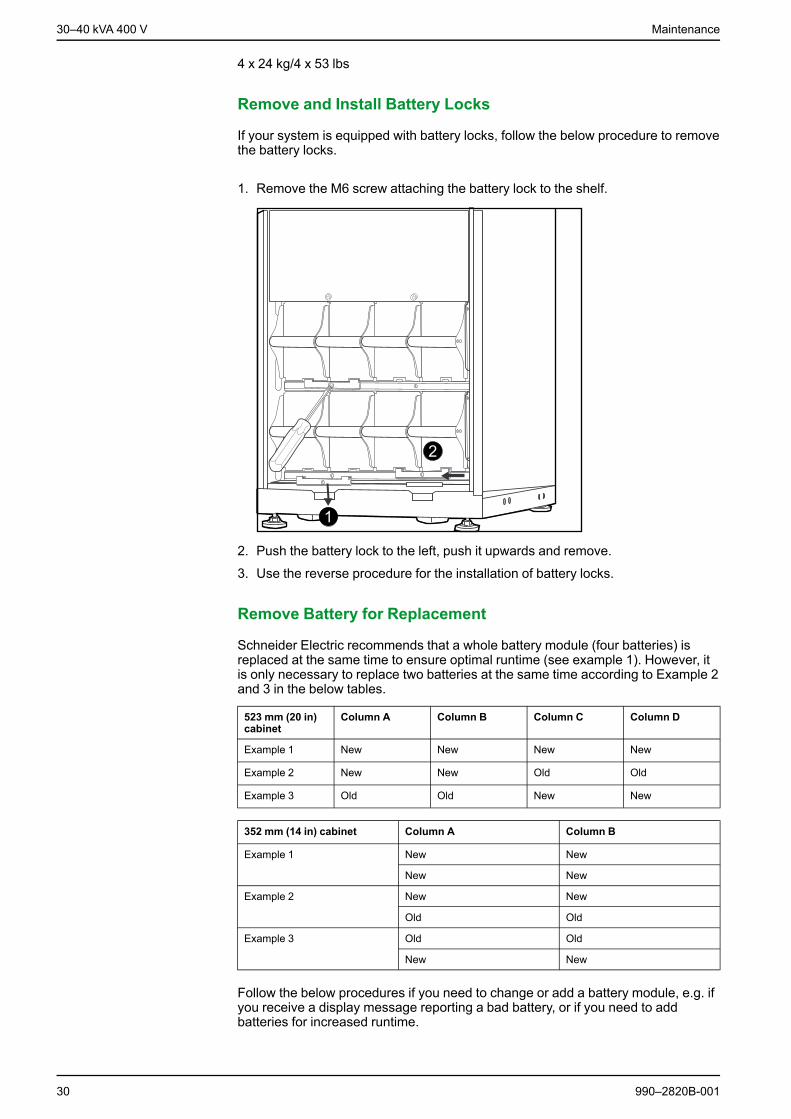
Remove and Install Battery Locks
If your system is equipped with battery locks, follow the below procedure to removethe battery locks.
1. Remove the M6 screw attaching the battery lock to the shelf.
2. Push the battery lock to the left, push it upwards and remove.
3. Use the reverse procedure for the installation of battery locks.
Remove Battery for Replacement
Schneider Electric recommends that a whole battery module (four batteries) isreplaced at the same time to ensure optimal runtime (see example 1). However, itis only necessary to replace two batteries at the same time according to Example 2and 3 in the below tables.
523 mm (20 in)cabinet
Column A Column B Column C Column D
Example 1 New New New New
Example 2 New New Old Old
Example 3 Old Old New New
352 mm (14 in) cabinet Column A Column B
Example 1 New New
New New
Example 2 New New
Old Old
Example 3 Old Old
New New
Follow the below procedures if you need to change or add a battery module, e.g. ifyou receive a display message reporting a bad battery, or if you need to addbatteries for increased runtime.
30 990–2820B-001

Maintenance 30–40 kVA 400 V
NOTE:When removing battery modules, start from the highest level and workdown.
1. Holding the battery handle, gently push the battery upwards and pull it halfwayout of the cabinet. A lock mechanism prevents it from being pulled all the wayout.
2. Release the locking mechanism by lifting the modular battery unit.
3. Pull the modular battery unit completely out while supporting it.
Install Batteries
UPS/Modular Battery Cabinet
1. Remove the blind plate (if present) in front of empty battery shelves (if present)and save the screws for later use.
2. Install the battery module in the lowest available bay (four across in 523 mm (20in) UPS versions, two across in 352 mm (14 in) UPS versions).
990–2820B-001 31

30–40 kVA 400 V Maintenance
3. Position the battery unit to slide in between the grooves and push it completelyinto the UPS to ensure connection.
NOTE: If a problem is reported, ensure that the battery modules are correctlyinstalled. If the problem persists, see the troubleshooting section.
NOTE: Allow for a 24-hour recharging period of the batteries after system start-up.
32 990–2820B-001

Troubleshooting 30–40 kVA 400 V
Troubleshooting
Status and Alarm MessagesThis section lists the status and alarm messages that the UPS might display. Themessages are listed in alphabetical order, and a suggested corrective action islisted with each alarm message to help you troubleshoot problems.
Display Messages
Display Message Description Corrective Action
Automatic Self Test Started. The UPS has started the preprogrammedbattery test.
No corrective action is necessary.
ABus Communication Fault. Communication fault detected on the ABus. Check ABus wiring. If this does not helpcontact Schneider Electric.
ABus Termination Fault. ABus termination is missing. Check if termination is present. If this doesnot help contact Schneider Electric.
Batt Temperature Exceeded Upper Limit. The temperature of one or more batteryunits has exceeded the systemspecifications.
Contact Schneider Electric CustomerSupport
Battery over-voltage warning. The battery voltage is too high and thecharger has been deactivated.
Contact Schneider Electric CustomerSupport
Bypass Not Available Input Freq/Volt OutOf Range.
The frequency or voltage is out ofacceptable range for bypass. This messageoccurs when the UPS is online, andindicates that the bypass mode may not beavailable if required.
Correct the input voltage to provide anacceptable voltage or frequency.
Battery Discharged. The UPS is in battery operation and thebattery charge is low. Note: Runtime islimited in duration.
No corrective action is necessary. Shutdown the system and the load equipment orrestore incoming voltage.
Emergency PSU Fault. The redundant Emergency Power SupplyUnit (PSU) is not working. The UPS willcontinue to work normally, but the PSUshould be replaced.
Contact Schneider Electric CustomerSupport
EPO Activated. The Emergency Power Off switch has beenactivated.
Deactivate the Emergency Power Offswitch.
Fan fault. A fan has failed. Contact Schneider Electric CustomerSupport
Int. Mech. Bypass Switch Closed. The internal mechanical switchgear isclosed.
No corrective action necessary. The UPS isin internal mechanical bypass operation.
Int. Mech. Bypass Switch Open. The internal mechanical switchgear is OFF. No corrective action is necessary.
Low-Battery. The UPS is in battery operation and thebattery charge is low. Note: Runtime islimited in duration.
Shut down the system and the loadequipment or restore incoming voltage.
Load Is No Longer Above AlarmThreshold.
The load previously exceeded the alarmthreshold and the situation has beencorrected either because the loaddecreased or the threshold was increased.
No corrective action is necessary.
Load Power Is Above Alarm Threshold. The load has exceeded the user-specifiedload alarm threshold.
Option 1: Use the display interface to raisethe alarm threshold.Option 2: Reduce the load.
Mains Not Available. Input Freq/Volt Outof Range.
The frequency or voltage is out ofacceptable range for normal operation.
Correct the input voltage to provideacceptable voltage or frequency.
Minimum Runtime Restored. The system runtime dropped below theconfigured minimum and has been restored.Additional Battery Modules were installed,the existing Battery Modules wererecharged, the load was reduced, or thethreshold was decreased.
No corrective action is necessary.
990–2820B-001 33

30–40 kVA 400 V Troubleshooting
Display Message Description Corrective Action
No Batteries Are Connected. No battery power is available. Check that the batteries are insertedproperly.
No Master is Present in the ParallelSystem.
No parallel master is present. The parallelsystem will not be able to function properly.
Contact Schneider Electric CustomerSupport
Number of Battery Modules Decreased. One or more battery modules wereremoved.
No corrective action is necessary.
Number of Battery Modules Increased. One or more battery modules were added. No corrective action is necessary.
Overload on a Parallel Unit. One or more systems has overload. Notethat the entire parallel system will not beable to return from bypass.
No corrective action is necessary.
Order Startup Check. The UPS system has been on for five days. Contact Schneider Electric CustomerSupport to verify the installation.
Order Tech Check. The UPS system has been on for four years.A technical check is recommended.
Contact Schneider Electric CustomerSupport.
PBus Communication Fault on Cable 1. Communication fault detected on PBus 1. Check PBus 1 wiring.If this does not help contact SchneiderElectric.
PBus Communication Fault on Cable 2. Communication fault detected on PBus 2. Check PBus 2 wiring.If this does not help contact SchneiderElectric.
PBus Termination Fault on Cable 1. PBus 1 termination is missing. Check if termination is present. If this doesnot help contact Schneider Electric.
PBus Termination Fault on Cable 2. PBus 2 termination is missing. Check if termination is present. If this doesnot help contact Schneider Electric.
Parallel Configuration Fault. The parallel system has not been configuredcorrect.
Contact Schneider Electric CustomerSupport.
Parallel Redundancy Restored. The parallel redundancy has been restored. No corrective action is necessary.
Parallel Redundancy is below AlarmThreshold
The load has exceeded the user specifiedload alarm threshold.
Option 1: Use the display interface to raisethe alarm thresholdOption 2: Reduce the load. Parallelredundancy is now restored.
Replace Batt(s). One or more Battery Modules needreplacement (only applicable with internalbatteries).
See Parts Replacement, page 27 forprocedures.
Runtime Is Below Alarm Threshold. The predicted runtime is lower than theuser-specified minimum runtime alarmthreshold. Either the battery capacity hasdecreased, or the load has increased.
Option 1: Allow the battery modules torecharge.Option 2: If possible, increase the number ofbattery modules.Option 3: Reduce the load.Option 4: Decrease the alarm threshold.Contact Schneider Electric CustomerSupport.
Shutdown Due To Low Battery. The UPS was in Battery Operation and shutdown the load when no more battery powerwas available.
No corrective action is necessary.Note: If the problem reoccurs, considerincreasing the battery capacity.
Site Wiring Fault. Wrong phase rotation on the input side. TheUPS will continue to supply conditionedpower from batt.
An electrician should check that the UPShas been wired properly.
Static Bypass Switch Fault. The Static Bypass Switch has failed. Contact Schneider Electric CustomerSupport.
System Failure Detected by Surveillance. The system has detected an internal error. Check for other alarms and contactSchneider Electric customer support if theproblem persists.
System Start Up Configuration Failed. System configuration error. Unable todetermine system voltage and/or cabinetsize.
Check for other alarms and contactSchneider Electric customer support if theproblem persists.
System Not Synchronized to Bypass. The system cannot synchronize to bypass.The mode may not be available.
Option 1: Decrease the input frequencysensitivity.Contact Schneider Electric CustomerSupport.Option 2: Correct the bypass input voltage toprovide acceptable voltage or frequency.
34 990–2820B-001

Troubleshooting 30–40 kVA 400 V
Display Message Description Corrective Action
The dust filter must be changedimmediately.
- Replace the dust filter.
The dust filter must be changed soon. - Be prepared to change the dust filter soon.
UPS In Bypass Due To Fault. The UPS has transferred to Bypass Modebecause a fault has occurred.
Contact Schneider Electric CustomerSupport.
UPS In Bypass Due To Overload. The load exceeded the power capacity. TheUPS has switched to Bypass Mode.
Decrease the load.
UPS Is Overloaded. The load exceeded the system powercapacity.
Option 1: Decrease the load.Option 2: Check the load distribution on the3 phases via the display. If the load isunevenly distributed, adjust the loaddistribution.
Warranty Expiring. The warranty expires in three months. Contact Schneider Electric CustomerSupport.
Weak Batt(s) Detected. ReducedRuntime.
One or more weak batteries detected. Replace the weak batteries.
XR Battery Fuse Blown. Modular battery fuse blown. Runtime islower than expected.
Replace the blown fuse in the modularbattery cabinet (only applicable if yourinstallation includes a modular batterycabinet).
990–2820B-001 35

Printed in.Schneider Electric
Schneider Electric35 rue Joseph Monier92500 Rueil MalmaisonFrance
+ 33 (0) 1 41 29 70 00
www.schneider-electric.com
As standards, specifications, and design change from time to time,please ask for confirmation of the information given in this publication.
© 2006 – 2015 Schneider Electric. All rights reserved.
990–2820B-001