smart wireless gateway - fmtech wireless gateway-menual.pdf · installation of this device in an...
TRANSCRIPT

www.emersonprocess.com
¢00825-0200-4420[¤
Quick Installation Guide00825-0200-4420, Rev CAJuly 2010
Wireless Considerations
Step 1: Initial Connection and Configuration
Step 2: Physical Installation
Step 3: Software Installation (optional)
Step 4: Verify Operations
Product Certifications
EC Declaration of Conformity
Start
End
Smart Wireless Gateway
00825-0200-4420_CA.fm Page 1 Wednesday, July 28, 2010 11:09 AM

Quick Installation Guide00825-0200-4420, Rev CA
July 2010
00825-0200-4420_CA.fm Page 2 Wednesday, July 28, 2010 11:09 AM
© 2010 Rosemount Inc. All rights reserved. All marks property of owner.
IMPORTANT NOTICE
This installation guide provides basic guidelines for the Smart Wireless Gateway. It does not provide instructions for diagnostics, maintenance, service, or troubleshooting. Refer to the Smart Wireless Gateway Reference Manual (Document Number 00809-0200-4420) for more information and instructions. The manual and this QIG are available electronically on www.emersonprocess.com.
WARNING
Explosions could result in death or serious injury:
Installation of this device in an explosive environment must be in accordance with the appropriate local, national, and international standards, codes, and practices. Please review the Product Certifications section for any restrictions associated with a safe installation.
Avoid contact with the leads and terminals. High voltage that may be present on leads can cause electrical shock. This device complies with Part 15 of the FCC Rules. Operation is subject to the following conditions. This device may not cause harmful interference. This device must accept any interference received, including interference that may cause undesired operation. This device must be installed to ensure a minimum antenna separation distance of 20 cm from all persons.
Emerson Process Management 8200 Market BoulevardChanhassen, MN USA 55317T (US) 800 999 9307T (Intnl) 952 906 8888F 952 949 7001
Emerson Process ManagementFrankenstrasse 2163791 KarlsteinGermanyT 49 6188 992 0F 49 6188 992 112
Emerson Process Management Asia Pacific Private Limited1 Pandan CrescentSingapore 128461T 65 6777 8211F 65 6777 0947 / 65 6777 [email protected]
Emerson Process Management No. 6 North Street, Hepingli, Dong Cheng DistrictBeijing 100013, ChinaT 86 10 6428 2233F 86 10 6422 8586
2

Quick Installation Guide00825-0200-4420, Rev CAJuly 2010
00825-0200-4420_CA.fm Page 3 Wednesday, July 28, 2010 11:09 AM
WIRELESS CONSIDERATIONS
Power Up SequenceThe Smart Wireless Gateway (Gateway) should be installed and functioning properly before Power Modules are installed in any wireless field devices. Wireless field devices should also be powered up in order of proximity from the Smart Wireless Gateway beginning with the closest. This will result in a simpler and faster network installation.
Antenna PositionThe antenna should be positioned vertically, and be approximately 3 ft. (1 m) from large structures or buildings to allow for clear communication to other devices.
Mounting HeightFor optimal wireless coverage, the Gateway or remote antenna is ideally mounted 15-25 ft. (4,6 - 7,6 m) above ground or 6 ft. (2 m) above obstructions or major infrastructure.
GENERAL CONSIDERATIONS
PC RequirementsOperating System
• Windows 2000, service pack 4• Windows Server, 2003• Windows XP (Home or Professional), service pack 1 or higher
Applications
• Internet Explorer 6.0 or higher• Mozilla Firefox 1.5 or higher• .Net Framework 2.0 (for OPC proxy only)
Hard Disk Space
• AMS™ Wireless Configurator: 1.5 GB• Gateway Setup CD: 250 MB
3
Quick Installation Guide00825-0200-4420, Rev CA
July 2010
00825-0200-4420_CA.fm Page 4 Wednesday, July 28, 2010 11:09 AM
4
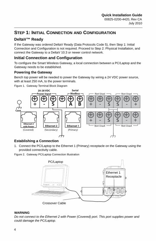
STEP 1: INITIAL CONNECTION AND CONFIGURATION
DeltaV™ ReadyIf the Gateway was ordered DeltaV Ready (Data Protocols Code 5), then Step 1: Initial Connection and Configuration is not required. Proceed to Step 2: Physical Installation, and connect the Gateway to a DeltaV 10.3 or newer control network.
Initial Connection and ConfigurationTo configure the Smart Wireless Gateway, a local connection between a PC/Laptop and the Gateway needs to be established.
Powering the GatewayBench top power will be needed to power the Gateway by wiring a 24 VDC power source, with at least 250 mA, to the power terminals.
Figure 1. Gateway Terminal Block Diagram
Establishing a Connection1. Connect the PC/Laptop to the Ethernet 1 (Primary) receptacle on the Gateway using the
provided connectivity cable.
Figure 2. Gateway PC/Laptop Connection Illustration
WARNINGDo not connect to the Ethernet 2 with Power (Covered) port. This port supplies power and could damage the PC/Laptop.
+ +
+
+
+
-
- -
--A B S S
S S
20-28 VDCPower Input
SerialModbus Not Used Not Used
Not Used Not Used
Case
(Covered)
S
Ethernet 2 with Power Ethernet 2 Ethernet 1
(Secondary) (Primary)
+ +
+
+
+
-
- -
--A B S S
S S
S
24 V DC24 V DCPower InputPower Input ModbusModbus Not UsedNot Used Not UsedNot Used
Not UsedNot Used Not UsedNot Used
CaseCase
S
POEPOE P2P2 P1P1
Ethernet 1 Receptacle
Crossover Cable
PC/Laptop

Quick Installation Guide00825-0200-4420, Rev CAJuly 2010
00825-0200-4420_CA.fm Page 5 Wednesday, July 28, 2010 11:09 AM
STEP 1 CONTINUED...2. To establish the PC/Laptop settings begin with Start>Settings>Network Connections.
a. Select Local Area Connection.b. Right click to select Properties.c. Select Internet Protocol (TCP/IP), then click the Properties button.
NOTE:If the PC/Laptop is from another network, record the current IP address and other settings so the PC/Laptop can be returned to the original network after the Gateway has been configured.
d. Select the Use the following IP address button e. Input 192.168.1.12 in the IP address block.f. Input 255.255.255.0 in the Subnet Mask.g. Select OK for both the Internet Protocol (TCP/IP) Properties window and the Local
Area Connection Properties window.
NOTE:Connecting to the Gateway's secondary Ethernet port will require different network settings. Please see Table 1 for additional network settings.
Table 1. Default IP Addresses
Gateway PC / Laptop
Ethernet 1 192.168.1.10 192.168.1.12Ethernet 2 192.168.2.10 192.168.2.12Ethernet 1 (DeltaV Ready) 10.5.255.254 10.5.255.200Ethernet 2 (DeltaV Ready) 10.9.255.254 10.9.255.200
5
Quick Installation Guide00825-0200-4420, Rev CA
July 2010
00825-0200-4420_CA.fm Page 6 Wednesday, July 28, 2010 11:09 AM
6
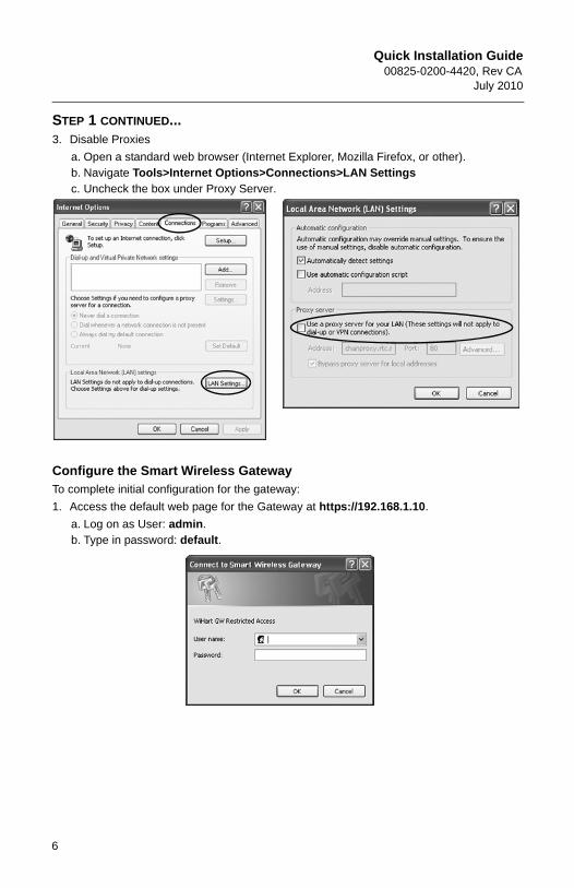
STEP 1 CONTINUED...3. Disable Proxies
a. Open a standard web browser (Internet Explorer, Mozilla Firefox, or other).b. Navigate Tools>Internet Options>Connections>LAN Settings c. Uncheck the box under Proxy Server.
Configure the Smart Wireless GatewayTo complete initial configuration for the gateway:
1. Access the default web page for the Gateway at https://192.168.1.10.
a. Log on as User: admin.b. Type in password: default.

Quick Installation Guide00825-0200-4420, Rev CAJuly 2010
00825-0200-4420_CA.fm Page 7 Wednesday, July 28, 2010 11:09 AM
STEP 1 CONTINUED...
2. Navigate to Setup>Ethernet Protocol>Address to enter the Network Settings.
a. Configure a static IP Address or set for DHCP and enter a Hostnameb. Restart Application at Setup>Restart Apps.
3. Disconnect the power and Ethernet from the Gateway.
7

Quick Installation Guide00825-0200-4420, Rev CA
July 2010
00825-0200-4420_CA.fm Page 8 Wednesday, July 28, 2010 11:09 AM
STEP 2: PHYSICAL INSTALLATION
Pipe MountTools Needed:
• 2-in. (51 mm) mounting pipe or mast• Two 5/16-in. (7,9 mm) u-bolts supplied with Gateway• 1/2-in. socket-head wrench
For installing the Gateway in a pipe mount:
1. Insert one u-bolt around the pipe, through the top mounting holes of the Gateway enclosure, and through the washer plate.
2. Use a 1/2-in. socket-head wrench to fasten the nuts to the u-bolt.
3. Repeat for the second u-bolt and the lower mounting holes.
BEST PRACTICEIf the Gateway was ordered with Output Code 2, run a secondary Ethernet Cable when installing cable conduit from the Gateway to a convenient indoor location to simplify future configuration changes.
8

Quick Installation Guide00825-0200-4420, Rev CAJuly 2010
00825-0200-4420_CA.fm Page 9 Wednesday, July 28, 2010 11:09 AM
STEP 2 CONTINUED...
Remote Antenna (Optional)The remote antenna options provide flexibility for mounting the Gateway based on wireless connectivity, lightning protection, and current work practices.
Remote mount antenna kits include weatherproof tape for use on the cable connections, and a mounting kit for the lightning arrestor and antenna. The following diagram and table describe each remote antenna kit option.
Table 2. Remote Antenna Kit Options
WARNING
When installing a remote mount antenna for the Smart Wireless Gateway, use established safety procedures to avoid falling or to avoid contacting high-power electrical lines.
Install remote antenna components for the Smart Wireless gateway in compliance with local and national electrical codes and use best practices for lightning protection.
Before installation, consult with the local area electrical inspector, electrical officer, and work area supervisor.
The Smart Wireless Gateway remote antenna options are specifically engineered to provide installation flexibility while optimizing wireless performance and maintaining local spectrum approvals. Each remote antenna kit contains 50 ft. (15,2 m) of LMR-400 coaxial cable, and a high-gain antenna. To maintain wireless performance and avoid non-compliance with local spectrum regulations, do not change the length or type of coaxial cable, or the antenna type.
Emerson Process Management is not responsible for wireless performance, or non-compliance with local spectrum regulations, if the supplied remote antenna kit is not used as specified in this document.
Kit Option Antenna Cable 1 Cable 2 Lightning Arrestor
WL2 1/2 Wavelength Dipole Omni-Directional +6 dB Gain
50 ft. (15,2 m) LMR-400
N/A Head mount, jack to plugGas discharge tube0.5 dB insertion loss
WL3 1/2 Wavelength Dipole Omni-Directional +6 dB Gain
30 ft. (9,1 m) LMR-400
20 ft. (6,1 m) LMR-400
In-line, jack to jackGas discharge tube0.1 dB insertion loss
WL4 1/2 Wavelength Dipole Omni-Directional +6 dB Gain
40 ft. (12,2 m) LMR-400
10 ft. (3,0 m)LMR-400
In-line, jack to jackGas discharge tube0.1 dB insertion loss
9

Quick Installation Guide00825-0200-4420, Rev CA
July 2010
00825-0200-4420_CA.fm Page 10 Wednesday, July 28, 2010 11:09 AM
STEP 2 CONTINUED...
The Remote Omni-Antenna kit includes sealant tape for remote antenna connection, as well as mounting brackets for the antenna, Lightning Arrestor, and the Smart Wireless Gateway.
WL2, WL3, and WL4 are optimal for installations requiring lightning protection. WL3 and WL4 provide lightning protection along with the ability to have the Gateway mounted indoors, the antenna mounted outdoors, and the lightning arrestor mounted at the building egress.
NOTEThe coaxial cables on the remote antenna options WL3 and WL4 are interchangeable for installation convenience.
The remote antenna should be located for optimal wireless performance. Ideally, 15 - 25 ft. (4,6 - 7,6 m) above the ground or 6 ft. (2 m) above obstructions or major infrastructure.
Installation of the WL2 Option:
1. Mount the antenna on a 2-in. (0.05 m) pipe mast using the supplied equipment.
2. Attach the lightning arrestor to the top of the Gateway.
3. Use the LMR-400 coaxial cable to connect the antenna to the lightning arrestor.
4. Seal each connection between the Gateway, lightning arrestor, cable, and antenna with the weatherproof tape.
Antenna
50 ft. (15,2 m) cable
Lightning Arrestor
WL2WL2
Antenna
40 ft. (12,2 m) cable
Lightning Arrestor
10 ft. (3,0 m) cable
WL4*WL4*
Interchangeable cables
Antenna
30 ft. (9,1 m) cable
Lightning Arrestor
20 ft. (6,1 m) cable
WL3*WL3*
Interchangeable cables
10

Quick Installation Guide00825-0200-4420, Rev CAJuly 2010
00825-0200-4420_CA.fm Page 11 Wednesday, July 28, 2010 11:09 AM
STEP 2 CONTINUED...
Installation of the WL3/WL4 Option:
1. Mount the antenna on a 2-in. (0.05 m) pipe mast using the supplied equipment.
2. Mount the lightning arrestor using the supplied equipment, minimizing the distance between it and the building egress for optimal lightning protection.
3. Use the LMR-400 coaxial cables to connect the Gateway, lightning arrestor, and antenna.
4. Seal each connection between the Gateway, lightning arrestor, cables, and antenna with weatherproof tape.
Any spare lengths of coaxial cable should be placed in 12-in. (0,3 m) coils.
Ensure that the mounting mast and lightning arrestor are grounded in accordance with local/national electrical codes.
NOTE:Be sure to apply weatherproof tape to all remote antenna connections. The tape provided is self fusing silicone tape which must be stretched during application in order to form a proper seal. This tape is intended for single use, do not reuse.
Example of Mounting a Remote Antenna
Ground to Lightning Arrestor
Control/Equipment Room
Remote Antenna outside of enclosure
Ground to Gateway
Lightning Arrestor
Antenna mounted6 ft. (2 m) above obstruction or majorinfastructure
0 ft. (0 m)
6 ft. (2 m)
Gateway Insidethe Building
CableCable
CableBuilding Egress
11

Quick Installation Guide00825-0200-4420, Rev CA
July 2010
00825-0200-4420_CA.fm Page 12 Wednesday, July 28, 2010 11:09 AM
Connect to the Host System1. Wire the Gateway’s Ethernet 1 (Primary) or Serial Output connection to the Host System
Network or Serial I/O.2. For Serial connections, connect A to A, B to B, making sure all terminations are clean
and secured to avoid wiring connection problems.
Figure 3. Smart Wireless Gateway Terminal Block Diagram
WARNINGDo not connect the Host System to the Ethernet 2 with Power (Covered) port on the Smart Wireless Gateway to avoid damaging the system.
BEST PRACTICETwisted shielded pair cable is generally used to wire the Serial connection, and it is standard practice to ground the shield on the Serial Host side leaving the shield floating on the Gateway side. To avoid grounding issues be sure to insulate the shield.
PowerWire a 24 VDC power source, with at least 250 mA of current, to the power terminals using the Smart Wireless Gateway Terminal Block Diagram shown in Figure 3.
+ +
+
+
+
-
- -
--A B S S
S S
20-28 VDCPower Input
SerialModbus Not Used Not Used
Not Used Not Used
Case
(Covered)
S
Ethernet 2 with Power Ethernet 2 Ethernet 1
(Secondary) (Primary)
12

Quick Installation Guide00825-0200-4420, Rev CAJuly 2010
00825-0200-4420_CA.fm Page 13 Wednesday, July 28, 2010 11:09 AM
STEP 3: SOFTWARE INSTALLATION (OPTIONAL)The 2 disk software pack contains the Security Setup Utility (only required for secure host connections or OPC communications) and AMS Wireless Configurator. The Security Setup Utility is located on Disk 1. To install the software:
1. Exit/close all Windows programs, including any running in the background, such as virus scan software.
2. Insert Disk 1 into the CD/DVD drive of the PC.
3. Follow the prompts.
AMS Wireless Configurator is located on Disk 2. To install the software:
1. Exit/close all Windows programs, including any running in the background, such as virus scan software.
2. Insert Disk 2 into the CD/DVD drive of the PC.
3. Click Install from the menu when the AMS Wireless Configurator setup begins.
4. Follow the prompts.
5. Allow AMS Wireless Configurator to reboot PC.
6. Do not remove the disk from the CD/DVD drive.
7. Installation will resume automatically after login.
8. Follow the prompts.
NOTE:If the autorun function is disabled on the PC, or installation does not begin automatically, double click D:\SETUP.EXE (where D is the CD/DVD drive on the PC) and click OK.
For more information about the Security Setup Utility and AMS Wireless Configurator, see the Smart Wireless Gateway Reference Manual (doc. # 00809-0200-4420).
13

Quick Installation Guide00825-0200-4420, Rev CA
July 2010
00825-0200-4420_CA.fm Page 14 Wednesday, July 28, 2010 11:09 AM
14
STEP 4: VERIFY OPERATIONSOperation is verified through the web interface by opening a web browser from any PC on the host system network and entering the Gateway IP address or DHCP host name in the address bar. If the Gateway has been connected and configured properly, the Security Alert will be displayed followed by the log in screen.
Figure 4. Gateway Log In Screen
The Gateway is now ready to be integrated into the host system. If wireless field devices were ordered with the Gateway, they were preconfigured with the same Network ID and Join Key information. Once the field devices are powered, they will appear on the wireless network and communications can be verified under the Explore tab using the web interface. The time needed for the network to form will depend on the number of devices.
For more detailed installation instructions, see the Smart Wireless Gateway Reference Manual (doc. # 00809-0200-4420). For software and integration support, call the Emerson Global Service Center
Emerson Global Service CenterSoftware and integration support:
United States: 1 800 833 8314International: 63 2 702 1111

Quick Installation Guide00825-0200-4420, Rev CAJuly 2010
00825-0200-4420_CA.fm Page 15 Wednesday, July 28, 2010 11:09 AM
15
PRODUCT CERTIFICATIONS
Approved Manufacturing LocationsRosemount Inc. - Chanhassen, Minnesota, USAEmerson Process Management GmbH & Co. - Karlstein, GermanyEmerson Process Management Asia Pacific Private Limited - SingaporeBeijing Rosemount Far East Instrument Co., Limited - Beijing, China
Telecommunication ComplianceAll wireless devices require certification to ensure that they adhere to regulations regarding the use of the RF spectrum. Nearly every country requires this type of product certification. Emerson is working with governmental agencies around the world to supply fully compliant products and remove the risk of violating country directives or laws governing wireless device usage.
FCC and ICThis device complies with Part 15 of the FCC Rules. Operation is subject to the following conditions: This device may not cause harmful interference. This device must accept any interference received, including interference that may cause undesired operation. This device must be installed to ensure a minimum antenna separation distance of 20 cm from all persons.
Ordinary Location Certification for FMAs standard, the Gateway has been examined and tested to determine that the design meets basic electrical, mechanical, and fire protection requirements by FM, a nationally recognized testing laboratory (NRTL) as accredited by the Federal Occupational Safety and Health Administration (OSHA).
North American Certifications
N5 FM Division 2, Non-IncendiveCertificate Number: 3028321Nonincendive for Class I, Division 2, Groups A, B, C, and D.Dust Ignition-proof for Class II, III, Division 1, Groups E, F, and G; Indoors/outdoor locations;NEMA Type 4XTemperature Code: T4 (-40 °C < Ta < 70 °C)
Canadian Standards Association (CSA)
N6 CSA Division 2, Non-IncendiveCertificate Number: 1849337Suitable for Class I, Division 2, Groups A, B, C, and D.Dust Ignition-proof for Class II, Groups E, F, and G; Suitable for Class III Hazardous Locations.;Install per Rosemount drawing 01420-1011.Temperature Code: T4 (-40 °C < Ta < 70 °C)CSA Enclosure Type 4X

Quick Installation Guide00825-0200-4420, Rev CA
July 2010
00825-0200-4420_CA.fm Page 16 Wednesday, July 28, 2010 11:09 AM
16
European Union Directive InformationThe EC declaration of conformity for all applicable European directives for this product can be found on the Rosemount website at www.rosemount.com. A hard copy may be obtained by contacting your local sales representative.
ATEX Directive (94/9/EC)
Emerson Process Management complies with the ATEX Directive.
Electro Magnetic Compatibility (EMC) (2004/108/EC)
Emerson Process Management complies with the EMC Directive.
Radio and Telecommunications Terminal Equipment Directive (R&TTE)(1999/5/EC)
Emerson Process Management complies with the R&TTE Directive
European Certification
N1 ATEX Type n Certificate Number: Baseefa 07ATEX0056XATEX Marking: Ex II 3 GEEx nA Nl IIC T4 (-40 °C < Ta < 70 °C)Special Conditions for Safe Use (X)
The surface resistivity of the antenna is greater than one gigaohm. To avoid electrostatic charge build-up, it must not be rubbed or cleaned with solvents or a dry cloth.
The Apparatus is not capable of withstanding the 500V insulation test required by Clause 9.4 of EN 60079-15: 2005. This must be taken into account when installing the apparatus.
ND ATEX DustCertificate Number: Baseefa 07ATEX0057EX tD A 22 IP66 T135 (-40 °C < Ta < 70 °C)EEx nA nL IIC T4 T4 (-40 °C < Ta < 70 °C) II 3DVmax = 28V
N7 IECEx Type n Certificate Number: IECEx BAS 07.0012XEx nC IIC T4 (-40 °C =< Ta <=70 °C)Rated Voltage: 28VSpecial conditions for safe use (X)
The surface resistivity of the antenna is greater than one gigaohm. To avoid electrostatic charge build-up, it must not be rubbed or cleaned with solvents or a dry cloth.
The Apparatus is not capable of withstanding the 500V insulation test required by Clause 9.4 of EN 60079-15: 2005. This must be taken into account when installing the apparatus.
NF IECEx DustCertification Number: IECEx BAS 07.0013Ex tD A22 IP66 T135 (-40 °C < Ta < 70 °C)Vmax = 28V
Combination Certifications
KD Combination of N5, N6, and N1.
Quick Installation Guide00825-0200-4420, Rev CAJuly 2010
00825-0200-4420_CA.fm Page 17 Wednesday, July 28, 2010 11:09 AM
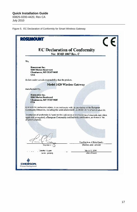
Figure 5. EC Declaration of Conformity for Smart Wireless Gateway
17

Quick Installation Guide00825-0200-4420, Rev CA
July 2010
00825-0200-4420_CA.fm Page 18 Wednesday, July 28, 2010 11:09 AM
18

Quick Installation Guide00825-0200-4420, Rev CAJuly 2010
00825-0200-4420_CA.fm Page 19 Wednesday, July 28, 2010 11:09 AM
19

Quick Installation Guide00825-0200-4420, Rev CA
July 2010
00825-0200-4420_CA.fm Page 20 Wednesday, July 28, 2010 11:09 AM
20