smartdraft 18 pconnect manual pconnect 18 manual.pdf · 2/27/2018 · calculation method. ......
TRANSCRIPT
Ignite your productivity.
SmartDraft 18 PConnect Manual
Updated: February 27, 2018 PConnect Version: 18.0.x
SmartDraft® is designed to make AutoCAD®, AutoCAD® Civil 3D®, AutoCAD® Map 3D and BricsCAD more productive
for civil engineers, mapping professionals, and surveyors. It is the result of extensive research and development, combined with many years of experience in the engineering field.
PConnect provides an easy to use and superior point-connection tool designed to combine the best features of attributed
point coding with an easily controlled, yet powerful, 2D and 3D line control language. PConnect's enhanced suffix codes give the operator increased flexibility and the ability to produce automated linework and layering. PConnect can use your company's specific description keys, combined with its suffix codes, to create robust geometry from surveyed data collected in the field. The linework is drawn on specified layers as defined by a Description Key Style file.
Requirements: AutoCAD Civil 3D 2012 – 2019 AutoCAD Map 3D 2012 – 2019 AutoCAD 2012 – 2019 BricsCAD v15 and 18 85 MB Free Disk Space for Installation
Supports:
Microsoft Windows® 7, 8, 8.1, and 10.
Does Not Support:
Any version of AutoCAD LT®
AutoCAD 2002 – 2011 based products
AutoCAD is a registered trademark of Autodesk, Inc. SmartDraft is a registered trademark of SmartDraft, Inc. Microsoft is a registered trademark of Microsoft Corporation. SmartDraft is a registered trademark of SmartDraft, Inc. All other brand names, product names, or trademarks belong to their respective holders. Copyright © 1989 - 2018, SmartDraft, Inc.
SmartDraft 18 PConnect Updated: February 27, 2018 Page 2 of 53
PConnect Overview
SmartDraft PConnect provides an easy to use and superior point-connection tool designed to combine the best features of
attributed point coding with an easily controlled, yet powerful, 2D and 3D line control language. PConnect's enhanced Suffix Codes give the operator increased flexibility and the ability to produce automated linework and layering. PConnect can use your company's specific description keys, combined with its suffix codes, to create robust geometry from surveyed data collected in the field. The linework is drawn on specified layers as defined by a Description Key Style file. Three pieces of data are used to achieve the desired linework: field-data, suffix codes, and the description key file. The field-data consists of point number, northing and easting coordinates, elevation, and description. Suffix codes instruct PConnect which type of calculations to perform when creating the linework between coordinates. The description key file specifies user-defined descriptions to process features (lines and curves) onto a user-specified layer name. PConnect supports field-data from:
• Civil 3D point objects;
• Civil 3D Survey database;
• Land Desktop project data;
• SmartDraft points; and
• An ASCII coordinate file in the PNEZD format. PConnect has three linework output options:
• 2D polylines, drawn at elevation 0 for planimetrics;
• 3D polylines (breaklines) drawn at the collected elevation; and
• Civil 3D survey figures drawn at the collected elevations from point data in the Survey database. The 3D polylines and/or Civil 3D survey figures can be used to create surfaces. User-defined descriptions are used to separate feature and line work. For example, the code EP could indicate edge of pavement. If there are two separate edges of pavement being collected in a cross-section method, the field crew could indicate the right edge of pavement as EP1 and the left edge of pavement as EP2. The command will draw a separate polyline for each code. In addition, PConnect has suffix codes that field crews can add to the description to instruct it to begin curves, end curves, draw templates, offset features, draw circles, squares, rectangles, extend a line, calculate a hidden right angle corner, end features, recall a point, and close a feature. With the combination of the descriptions and the suffix codes, field crews can reuse EP1 once a previous EP1 has been terminated using a terminate suffix code (.T, .CC, .CS, and .RCT).
Curves (Arcs)
• PConnect uses intelligent analysis of point relationships to create as correct a curve as possible, whether through two (2) or more points.
• A curve is started upon recognition of a curve suffix code (.PC, .BC, or .C3) provided there is/are point(s) following. Curved segments will continue to be created until an end of curve (.PT), closing straight (.CS), or terminate (.T) suffix code, or the last point of the unique description is encountered.
• Two-point curves (.PC followed immediately by a .PT) derive their shape from the direction of the previous or following straight tangent, depending on which is present. If there are only two (2) points, a straight segment is drawn.
• Using the Begin Curve (.PC) (Tangent) suffix code option and multiple points (three or more points), PConnect creates separate curved segments between each point.
• A 3-point curve (.C3) suffix code creates a non-tangent curve through the three (3) points. The code uses the starting point and the next two points with the same description key to calculate the curve. Note: If a third point is
SmartDraft 18 PConnect Updated: February 27, 2018 Page 3 of 53
not found or there is no terminate to suffix code (.T#) to a third point, PConnect defaults to the (.PC) curve calculation method.
• A Best-Fit curve (.BC) suffix code creates a non-tangent curve through three (3) or more points. The segments pass through all points creating a smooth curve consisting of arcs joining each pair of points. A minimum of three (3) points are required for a curve in one direction. Note: If a third point is not found or there is no terminator (.T#) to a third point, PConnect defaults to the (.PC) curve calculation method.
• 3D polylines cannot have true curved segments. To approximate a curve, PConnect draws 3D polylines containing additional vertices striking short chords along the path of the corresponding 2D curve.
Data Collection There are three (3) items to consider with collecting data: Points, Elevations, and Descriptions. Points
• Point numbers are processed in ascending order, except when the recall (.R#) or terminate to (.T#) suffix code is used.
• Point data can be collected, in the field, in either parallel (cross-sections) or sequential manner. See PConnect Cross Section Examples.
Elevations
• 2D polylines are always drawn at elevation 0.0, ignoring the point's elevation.
• 3D polylines are drawn using the point's elevation. PConnect treats points with invalid elevation as elevation 0.0. Since this will probably result in inaccurate interpolated elevations, make sure the points you are connecting with 3D polylines have real elevations.
• Elevations are interpolated linearly when adding intermediate points. Descriptions
• Point descriptions are used to identify geographic features.
• Unique descriptions are processed separately (e.g., EP1 is different than EP2, even if the description key is EP*).
• Descriptions can be used over and over again for separate features, if a terminate suffix code (.T, .CC, .CS, or .RCT) is used to end a feature. The next point number with the same description starts a new feature.
• Multiple descriptions can be entered for a single point. Each code must be separated by a space (e.g., 102.EP1 SWK1 BLDG1).
• To instruct the command not to process any special notes, add the "/" (forward slash) character before the note. This instructs the command not to process any information past the “/” character.
• If data is collected in a sequential manner (as in one curb line at a time), descriptions need not have a unique index added but must have a terminate code to instruct PConnect to end the feature.
• If data is collected in a parallel (cross-section) or random order, the description for the left must be different from the right (such as "TC1" and "TC2"). Otherwise, the resulting polyline will be drawn back and forth across the road.
• PConnect also provides suffix codes for beginning a tangent curve (.PC), ending a curve (.PT), closing a polyline (such as for an island or building), either straight (.CS), tangent curved (.CC), or 3 point non-tangent curve (.C3), terminating a polyline (.T), terminating a polyline to a point number (.T#), and recalling a point by its number (.R#).
• A polyline is drawn between the same description until a terminate suffix code (.T, .CC, .CS, or .RCT) or the last point with the same description is encountered.
• A point without a description will fail to match any description key and is excluded during processing.
SmartDraft 18 PConnect Updated: February 27, 2018 Page 4 of 53
Layers
• Unique description keys in the description key style can be assigned a hard-coded layer name or layer indexes from the SmartDraft layer database.
• The SmartDraft layer database has proposed, existing, and demolition (which can be set up as As-Built) layer types and also controls layer properties.
• PConnect will check all selected points and each attribute for the status of whether its layer is LOCKED or UNLOCKED. Stripping or replacing description values cannot be done if either the attribute layer or its parent "POINT" insertion layer is locked.
• If locked layers are encountered, PConnect will display their names and ask whether to unlock some or all of the layers. Leaving a layer locked will exclude the point(s) entirely from the selection, resulting in missing connection points, and ugly results most likely.
• If a layer is frozen or off, PConnect thaws or turns it on so the linework can be drawn.
SmartDraft 18 PConnect Updated: February 27, 2018 Page 5 of 53
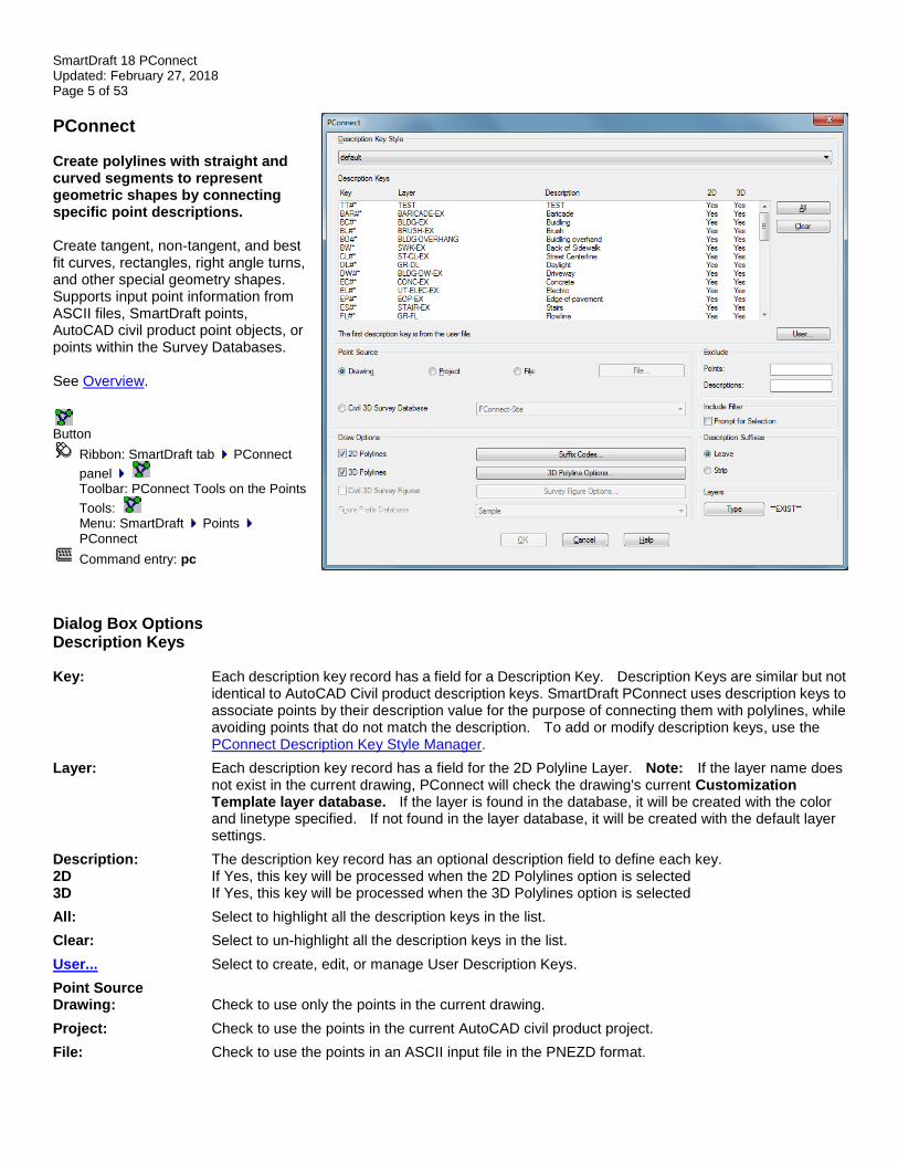
PConnect Create polylines with straight and curved segments to represent geometric shapes by connecting specific point descriptions. Create tangent, non-tangent, and best fit curves, rectangles, right angle turns, and other special geometry shapes. Supports input point information from ASCII files, SmartDraft points, AutoCAD civil product point objects, or points within the Survey Databases. See Overview.
Button
Ribbon: SmartDraft tab PConnect
panel Toolbar: PConnect Tools on the Points
Tools: Menu: SmartDraft Points
PConnect
Command entry: pc
Dialog Box Options Description Keys Key: Each description key record has a field for a Description Key. Description Keys are similar but not
identical to AutoCAD Civil product description keys. SmartDraft PConnect uses description keys to associate points by their description value for the purpose of connecting them with polylines, while avoiding points that do not match the description. To add or modify description keys, use the PConnect Description Key Style Manager.
Layer: Each description key record has a field for the 2D Polyline Layer. Note: If the layer name does not exist in the current drawing, PConnect will check the drawing's current Customization Template layer database. If the layer is found in the database, it will be created with the color and linetype specified. If not found in the layer database, it will be created with the default layer settings.
Description: The description key record has an optional description field to define each key. 2D If Yes, this key will be processed when the 2D Polylines option is selected 3D If Yes, this key will be processed when the 3D Polylines option is selected
All: Select to highlight all the description keys in the list.
Clear: Select to un-highlight all the description keys in the list.
User... Select to create, edit, or manage User Description Keys.
Point Source Drawing: Check to use only the points in the current drawing.
Project: Check to use the points in the current AutoCAD civil product project.
File: Check to use the points in an ASCII input file in the PNEZD format.
SmartDraft 18 PConnect Updated: February 27, 2018 Page 6 of 53
File... Select an ASCII point input file when the File option is selected.
Civil 3D Survey: Check to use the points in the selected Civil 3D Survey Database.
List: List of Civil 3D Survey Databases. Select the desired Survey Database.
Draw Options
2D Polylines: Select to create 2D polylines when processing. This instructs PConnect to draw 2D polylines at elevation 0.0 for the respective description key. The 2D polylines are drawn on the layer specified in the Layer field for the corresponding description key. A polyline will not be drawn with fewer than two (2) points. All polylines are drawn as LWPOLYLINEs (light-weight polylines).
3D Polylines: Select to create 3D polylines when processing. This instructs PConnect to draw 3D polylines at the elevation value and the respective description key. 3D polylines are drawn on the layer specified in the 3D Polylines... options. 3D polylines cannot have true curved segments but can have varying elevations for each point. To approximate a curve, 3D polylines must contain additional points creating short chords along the path of a curve. Elevations are interpolated linearly for the added points. A polyline will not be drawn with fewer than two (2) points.
Civil 3D Survey Figures: Select to create Civil 3D survey figures when processing. This instructs PConnect to draw Civil 3D survey figures at the elevation value and the respective description key. Civil 3D survey figures are drawn on the layer specified in the Figures... options. Elevations are interpolated linearly for the added points. A Civil 3D survey figure will not be drawn with fewer than two (2) points. This drawing option is only available when the Civil Survey point source is selected.
Suffix Codes Open the Description Key Suffix Codes options to set the description key suffix codes.
3D Polyline Options Open the 3D Polyline Options to set 3D polyline options.
Survey Figure Options Open the Figure Options to set Civil 3D survey figure options. This drawing option is only available when the Civil Survey point source is selected.
Figure Prefix Select the Figure Prefix Database to determine the layer that a survey figure is drawn on or how a Database: survey figure is stylized.
Exclude Points: Enter a range of point numbers to exclude (ignore) during processing. The format is:
1-300,302,310,500-600. No spaces, zeros, or negative numbers are allowed. It is useful to exclude points already processed.
Descriptions: Enter a series of descriptions to exclude (ignore) during processing. The format is: “WV,TCP,OG*,??,OAK.” Note: Wildcards are permitted, and excluded points are used with the recall and terminated with number Suffix Codes options.
Include Filter: Prompt for Selection: Click this option to be prompted for options to include only specified points. (e.g., All, Group,
Layers, Range, or Selection). When unchecked, All points are included.
Description Suffixes
Leave: Select to Leave the existing descriptions as-is (recommended).
Strip: Select to remove all suffix codes except the Description Key from the point’s description. For example, if a description key code is ".PC," the "TCDC.PC" would be stripped to the value, "TCDC."
Warning: Once the description key codes are stripped, you will not be able to run PConnect on those points again.
Layers
Type: Toggle for desired layer type. Note: If the description key style uses layer indexes, the layer name will change in the list; if the layer name was used, the layer name may not change.
OK: Select to process the selected Description Keys, Point Source, and options.
SmartDraft 18 PConnect Updated: February 27, 2018 Page 7 of 53
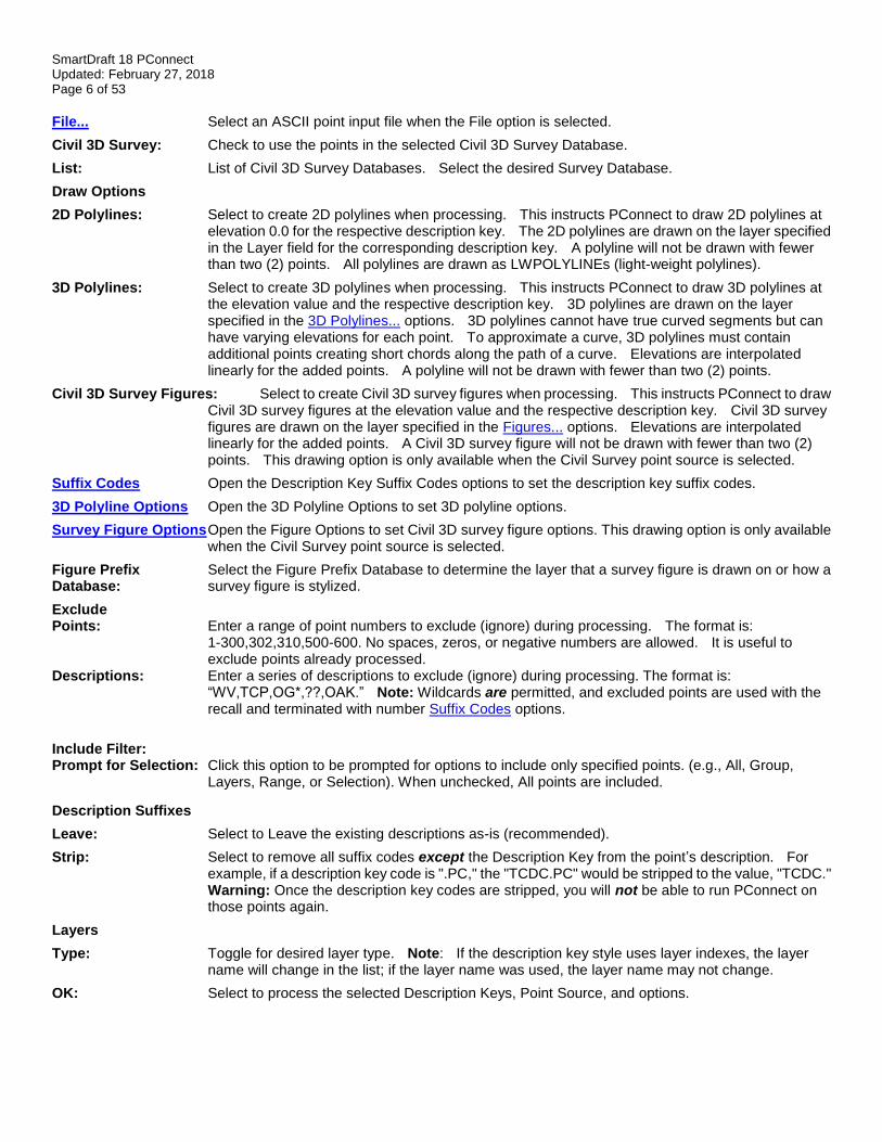
PConnect User Description Keys Select to create, edit, or manage User Description Keys. User Description Keys are not intended to list all the possible description keys used in a point file. But from time to time, a field crew will connect data for an item not listed in the Description Key Style. The User Description Keys allow the operator to add the description key to the list without modifying the Description Key Style. User Description Keys are appended to the selected list of Description Keys in the selected Description Key Style.
Dialog Box Options User Include a list of the description keys entered by the operator, the layer associated to the defined key, Description and an optional description to delineate the key. The user description keys will be appended to the Keys: current Description Key Style. Select a Description Key to edit or remove it. Add: Select option to add the key value, layer value, and description value in the edit boxes below the description
key list box. Note: Operator cannot add duplicate description keys. Remove: Remove the selected. Remove All: Remove all the User Description Keys listed. Update: Update the selected description key values with the values in the edit boxes. Note: Operator cannot
update if the key already exists in the list. Edit Boxes Key: Enter a description. The description key must have a unique value and can be numeric and/or character
based but cannot contain spaces. They are similar but not identical to AutoCAD Civil product description keys. PConnect uses description keys to associate points by their description value for the purpose of connecting them with polylines, while avoiding points that do not match the description. A description key may contain the wildcards such as *, ?, #, or @.
Layer: Enter a layer name to create the Polyline when processing the specified key. Note: If the layer name
does not exist in the current drawing, PConnect will check the current Customization Templates layer database. If the layer is found in the database, it will create it with the color and linetype specified; if not found in the layer database, it will be created with the default settings.
Description: Enter an optional note to describe the description key. 2D Enter Yes if this key is to be processed when the 2D Polylines option is selected in PConnect. 3D Enter Yes if this key is to be processed when the 3D Polylines option is selected in PConnect. Buttons Apply: Select to save changes and return to PConnect. Note: The User Description Key file is saved in your TEMP folder and is called “PConnectUser.dsy.”
SmartDraft 18 PConnect Updated: February 27, 2018 Page 8 of 53
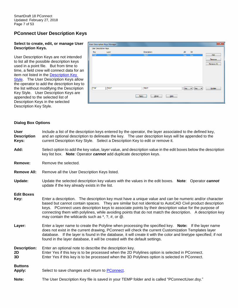
Suffix Codes Suffix Code Options for PConnect The following suffix codes are added to descriptions entered during data collection. These suffix codes instruct PConnect to make various calculations when connecting points to draw polylines.
Select the suffix code name below to display examples of linework drawn using the code.
Dialog Box Options Begin Curve (.PC): Enter the characters to represent the code to begin a tangent curve. Begin Curve uses the
previous segment, straight, or curved and the next point to calculate the tangent curve and continues to calculate tangent curves until it encounters an End Curve (.PT), Terminate (.T), Close Straight (.CS), or Close Curved (.CC) code.
Best Fit Curve (BC): Enter the characters to represent the code to begin a Best Fit Curve (multiple point) non-tangent
curve. The curve passes through all points creating a smooth curve consisting of curves joining each pair of points; a minimum of 3 points is required. PConnect uses the same Best Fit Curve calculation method as the AutoCAD Civil products.
3 Point Curve (.C3): Enter the characters to represent the code to begin a three (3) point non-tangent curve.
End Curve (.PT): Enter the characters to represent the code to end a curve.
Circle (.CR): (.CR#) Enter the characters to represent the code for drawing a circular polyline (multiple-sided polygon). The distance (#) value is the radius.
Square (.SQ): (.SQ#) Enter the characters to represent the code for drawing a square polyline (4-sided polygon). The distance (#) value is the length from the collected points to the edge of the square (1/2 the distance along one side of the square).
Turn 90 Angles Enter the characters followed by the distance or distances, separated by commas, to (.TN): (.TN#,#) instruct the command to place additional points after the current point at a right angle to the last
straight segment. Positive numbers are to the right (CW); negative numbers are to the left (CCW). The command assumes the previous segment was a straight segment, and this suffix code is ignored if it is in the middle of any of the curve suffix codes. It can be combined with termination codes (.T, .CS, and .CC) but requires at least one prior point to calculate the starting angle.
Right Angle Back Enter the characters to calculate a right angle point back from the current point. This suffix (.RA): code requires at least two prior points and at least one point to follow to calculate the angles.
Offset (.O): (.O#) Enter the characters to represent the code for offsetting the current polyline. The offset distance (#) is the number entered after the suffix code. Positive numbers are offset to the right; negative numbers are offset to the left. Note: If the command encounters another offset (.O) or middle (.M) with or without an offset distance (#), template (.ZT), or offset terminate, it ends the current offset.
Middle (.M): (.M#) Enter the characters to represent the code for offsetting middle. Offset middle is for collecting the middle of a feature. A polyline is NOT drawn along the original path, but polylines are drawn at 1/2 the width (#) on either side. Note: If the command encounters another offset (.O) or middle (.M) with or without an offset distance (#), template (.ZT), or offset terminate, it ends the current offset.

SmartDraft 18 PConnect Updated: February 27, 2018 Page 9 of 53
Elevation on Offsets Enter the characters to represent the code to adjust the elevation of offset polylines. This (.Z): suffix code does not adjust the elevation of an individual point or elevations along the primary
polyline. The suffix code also works with PConnect Templates to replace the first height value left of the field collected point. If this code is used without a height value, it sets the elevation adjustment to zero (0.0) for offsets and sets the template heights back to its designed height. This suffix code only applies to the Draw Options: 3D Polyline and Civil 3D Survey Figures. 2D Polylines are always drawn at elevation zero (0.0).
Templates (.ZT): Enter the characters to represent the code for templates. See Templates. A template is for collecting a single point along a feature in the field which follows a specific offset and height pattern. Add the template name to the suffix code to start using a template. Include the template suffix without a template name to end using a template. If the template is to be mirrored, add the "-" negative character before the template name (i.e., .ZT-CB1). To create a template, use the PConnect Template Manager. Note: If the command encounters another offset (.O) or middle (.M) with or without an offset distance (#), template (.ZT), or offset terminate (.OT), it ends the current template. The template suffix code can only be used with the first description assigned a point.
Terminate Offset Enter the characters to represent the code terminating an offset for either Offset (.O) or Middle (.OT): (.M). The difference between Terminate Offset (.OT) and Terminate (.T) is that offset terminate
does not terminate the primary polyline, just the offset polyline(s).
Close Straight Enter the characters to represent the code for closing a polyline with a straight segment. (.CS): Note: The next point encountered with the same description will start a new polyline.
Close Curved Enter the characters to represent the code for closing a polyline with a tangent (.CC): curved segment. Note: The next point encountered with the same description will start a new
polyline.
Terminate Enter the characters to represent the code for stopping a polyline with a specific description, (.T and .T#): so that the next sequence of points with the same description will start a new polyline. If the
current sequence of points with the same description was in the Best Fit Curve (.BC) instruction, Terminate (.T) would also end the curve. The terminate suffix code can only be combined with the Turn 90° Angles (.TN), Extend (.E), and Circle (.CR) codes. When combined with any other suffix codes, those codes will be ignored. Terminate (.T) also terminates any offsets or middles associated with the description.
Terminate to # The terminate suffix code can be followed by a point number. When the terminate suffix code (.T#): is followed by a point number (#), it terminates at the specified point. This allows a non- sequential
or previous point to be added to the end of a polyline, and the description of the specified point is ignored. This Terminate to (.T#) suffix code can be combined with the Begin Curve (.PC), End Curve (.PT), Right Angle Back, Turn 90° Angle (.TN), Extend (.E), and can be used on the point just following the 3-point curve (.C3).
Rectangle (.RCT): Enter the characters to create a closed rectangle from two points or closed right angle back to the starting point from three or more points. When using two points, an offset distance for the rectangle’s width, positive to the right and negative to the left, is required. For three or more points, do not enter an offset because it is ignored.
Extend (.E): (.E#) Enter the characters to represent the code for extending or shortening a segment along two points. When the distance (#) is a positive number, the segment is extended by the specified value; if the distance (#) is a negative number, the segment is shortened by the specified value.
Recall Point # (.R): Enter the characters to represent the code to recall a point (by number), to be used in sequence (.R#) before the current point. The description of the recalled point is ignored, so that the previous suffix
code (such as .PC or .PT) controls the curvature that is later applied to the recalled point. Beginning a new polyline at a point that recalls another point is equivalent to beginning the polyline as a straight segment from the recalled point.
Set Defaults Reset suffix codes to their default character values.
SmartDraft 18 PConnect Updated: February 27, 2018 Page 10 of 53
Set Defaults Values Supplied for the Suffix Codes The DEFAULTS suffix codes are stored outside the drawing in the file PConnect.ini in the current Customization Template folder. If this file is not found, the command will use the hard-coded defaults. The default description suffixes file is read only the first time the operator runs the command. Once read, the default values are stored in the operator’s AutoCAD profile.
• The suffix code for beginning a curve (.PC)
• The suffix code for beginning a curve fit / multiple point curve (.BC)
• The suffix code for beginning a 3-point curve (.C3)
• The suffix code for ending a curve (.PT)
• The suffix code for circle (.CR)
• The suffix code for square (.SQ)
• The suffix code for turn 90 degree angles (.TN)
• The suffix code for right angle back (.RA)
• The suffix code for offset (.O)
• The suffix code for middle (.M)
• The suffix code for elevation on offsets (.Z)
• The suffix code for templates (.ZT)
• The suffix code for terminate offset (.OT)
• The suffix code for closing a polyline curved (.CC)
• The suffix code for closing a polyline straight (.CS)
• The suffix code for terminating a polyline (.T)
• The suffix code for rectangle (.RCT)
• The suffix code for extend (.E)
• The suffix code for recalling a point (.R)
See Description Key Styles for more information about these files.

SmartDraft 18 PConnect Updated: February 27, 2018 Page 11 of 53
Code Entry Rules and Suggestions:
• All suffix codes must begin with the period "." as the first character. This approach should make the descriptions entered by the field crew more legible and tends to preclude any wildcard conflicts.
• All suffix codes must be added to the end of the description.
• All suffix codes are converted to upper case (as are descriptions) and stripped of leading and trailing spaces.
• Suffix code characters characters must be alphabetic characters only.
• Blank or duplicate values for suffix codes are not permitted.
• Do not use commas in the suffix codes, except to separate distances when using the Turn 90° Angles (.TN) suffix code.
• Do not use the "/" character in the suffix codes.
• Do not use commas in your description values.
• Suffix codes, that can be combined, can be combined in any order. PConnect analyzes the suffix data in an organized fashion to detect all possible combinations of description key suffix code data. The only exceptions to combining suffix codes are:
Example For point number 109, the following description key suffix codes will process the same.
G1.PC.R99.T150, G1.T150.R99.PC, or G1.R99.PC.T150: These suffix codes would be interpreted as connecting the recalled point 99, starting a curve at point 109, and terminating the polyline at point 150, respectively.
Also see Overview.
.PC.PT Requires at least one point between PC and PT
.PC.T (without the optional point number)
.CC.T (without the optional point number)
.CS.T (without the optional point number)
.CC.CS and all derivatives of the above
.CC.C3 CC is a terminator
.CC.BC CC is a terminator
.BC.T (without the optional point number)
.C3.T (without the optional point number)
.RCT.T Rectangle is already a termination code
.PC.RCT Rectangle code is ignored in curves
.BC.RCT Rectangle code is ignored in curves
.C3.RCT Rectangle code is ignored in curves
.C3.TN Turn Angle ignored within curves
.BC.TN Turn Angle ignored within curves
.PC.TN Turn Angle ignored within curves
.CS.C3 CS is a terminator
.CS.BC CS is a terminator
.CS.RCT Both are terminator codes
.CC.RCT Both are terminator codes
.T#.RCT Both are terminator codes
SmartDraft 18 PConnect Updated: February 27, 2018 Page 12 of 53
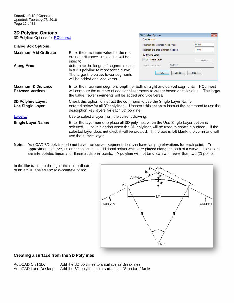
3D Polyline Options 3D Polyline Options for PConnect Dialog Box Options
Maximum Mid Ordinate Enter the maximum value for the mid ordinate distance. This value will be used to
Along Arcs: determine the length of segments used in a 3D polyline to represent a curve. The larger the value, fewer segments will be added and vice versa.
Maximum & Distance Enter the maximum segment length for both straight and curved segments. PConnect Between Vertices: will compute the number of additional segments to create based on this value. The larger
the value, fewer segments will be added and vice versa.
3D Polyline Layer: Check this option to instruct the command to use the Single Layer Name Use Single Layer: entered below for all 3D polylines. Uncheck this option to instruct the command to use the
description key layers for each 3D polyline.
Layer... Use to select a layer from the current drawing.
Single Layer Name: Enter the layer name to place all 3D polylines when the Use Single Layer option is selected. Use this option when the 3D polylines will be used to create a surface. If the selected layer does not exist, it will be created. If the box is left blank, the command will use the current layer.
Note: AutoCAD 3D polylines do not have true curved segments but can have varying elevations for each point. To
approximate a curve, PConnect calculates additional points which are placed along the path of a curve. Elevations are interpolated linearly for these additional points. A polyline will not be drawn with fewer than two (2) points.
In the illustration to the right, the mid ordinate of an arc is labeled Mc: Mid-ordinate of arc.
Creating a surface from the 3D Polylines AutoCAD Civil 3D: Add the 3D polylines to a surface as Breaklines. AutoCAD Land Desktop: Add the 3D polylines to a surface as "Standard" faults.
SmartDraft 18 PConnect Updated: February 27, 2018 Page 13 of 53
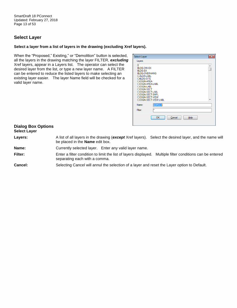
Select Layer Select a layer from a list of layers in the drawing (excluding Xref layers). When the “Proposed,” Existing,” or “Demolition” button is selected, all the layers in the drawing matching the layer FILTER, excluding Xref layers, appear in a Layers list. The operator can select the desired layer from the list, or type a new layer name. A FILTER can be entered to reduce the listed layers to make selecting an existing layer easier. The layer Name field will be checked for a valid layer name.
Dialog Box Options Select Layer
Layers: A list of all layers in the drawing (except Xref layers). Select the desired layer, and the name will be placed in the Name edit box.
Name: Currently selected layer. Enter any valid layer name.
Filter: Enter a filter condition to limit the list of layers displayed. Multiple filter conditions can be entered separating each with a comma.
Cancel: Selecting Cancel will annul the selection of a layer and reset the Layer option to Default.
SmartDraft 18 PConnect Updated: February 27, 2018 Page 14 of 53
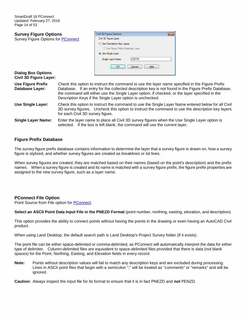
Survey Figure Options Survey Figure Options for PConnect
Dialog Box Options Civil 3D Figure Layer:
Use Figure Prefix Check this option to instruct the command to use the layer name specified in the Figure Prefix Database Layer: Database. If an entry for the collected description key is not found in the Figure Prefix Database,
the command will either use the Single Layer option, if checked, or the layer specified in the Description Keys if the Single Layer option is unchecked.
Use Single Layer: Check this option to instruct the command to use the Single Layer Name entered below for all Civil 3D survey figures. Uncheck this option to instruct the command to use the description key layers for each Civil 3D survey figure.
Single Layer Name: Enter the layer name to place all Civil 3D survey figures when the Use Single Layer option is selected. If the box is left blank, the command will use the current layer.
Figure Prefix Database The survey figure prefix database contains information to determine the layer that a survey figure is drawn on, how a survey figure is stylized, and whether survey figures are created as breaklines or lot lines. When survey figures are created, they are matched based on their names (based on the point's description) and the prefix names. When a survey figure is created and its name is matched with a survey figure prefix, the figure prefix properties are assigned to the new survey figure, such as a layer name.
PConnect File Option Point Source from File option for PConnect. Select an ASCII Point Data Input File in the PNEZD Format (point number, northing, easting, elevation, and description). This option provides the ability to connect points without having the points in the drawing or even having an AutoCAD Civil product. When using Land Desktop, the default search path is Land Desktop's Project Survey folder (if it exists). The point file can be either space-delimited or comma-delimited, as PConnect will automatically interpret the data for either type of delimiter. Column-delimited files are equivalent to space-delimited files provided that there is data (not blank spaces) for the Point, Northing, Easting, and Elevation fields in every record. Note: Points without description values will fail to match any description keys and are excluded during processing.
Lines in ASCII point files that begin with a semicolon ";" will be treated as "comments" or "remarks" and will be ignored.
Caution: Always inspect the input file for its format to ensure that it is in fact PNEZD and not PENZD.
SmartDraft 18 PConnect Updated: February 27, 2018 Page 15 of 53
PConnect Line Examples Suffix codes examples for PConnect.
Straight Segment Suffix Codes: PConnect has multiple straight segment suffix codes. Straight Segment: If no suffix codes are added to descriptions, a polyline with straight segments between the points is
created.
Close Straight (.CS): This suffix code closes a polyline back to the starting point using a straight segment.
Square (.SQ#): This suffix code draws a square polyline (4-sided polygon). The distance (#) is the length from the point to one edge of the square (one-half the distance along one of the square's sides).
Turn 90° Angle This suffix code adds straight segments turned at 90° angles from the previous segment. (.TN#,#): Multiple segments can be drawn with commas separating the distances (#) of the segments. If the
distance (#) is a positive number, the segment is turned right (CW); and if the distance (#) is a negative number, the segment is turned left (CCW).
Right Angle Back This suffix code calculates two straight segments forming a right angle. At least two (2) points (.RA): prior to the point with the code and one following are required for the calculations to be made.
Rectangle (.RCT#): This suffix code creates a closed rectangle from two points (with an offset distance) or closes back to the starting point at a right angle when three (3) or more points are used. When only two (2) points are used, the specified distance (#) is used to create a closed rectangle. If the specified distance (#) is a positive value, the width of the rectangle will be to the right; if the specified distance (#) is a negative value, the width of the rectangle will be to the left. When three (3) or more points are used, any specified distance is ignored. PConnect tries to calculate an intersection at right angles from the first and last segments.
Extend (.E#): This suffix code extends or shortens a straight segment along the bearing of the point with the code and the previous point. When the distance (#) is positive, the segment is extended; when the distance is (#) is negative, the segment is shortened.
Examples of Using Straight Segment Suffix Codes:
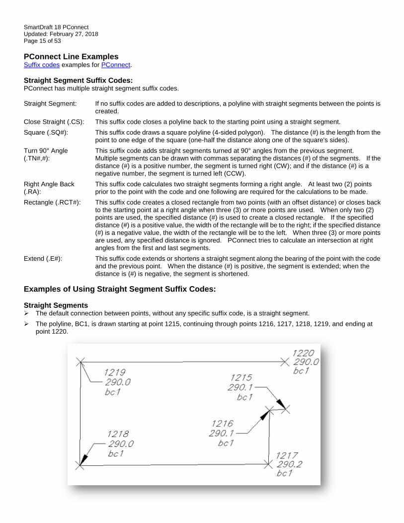
Straight Segments ➢ The default connection between points, without any specific suffix code, is a straight segment.
➢ The polyline, BC1, is drawn starting at point 1215, continuing through points 1216, 1217, 1218, 1219, and ending at point 1220.
SmartDraft 18 PConnect Updated: February 27, 2018 Page 16 of 53
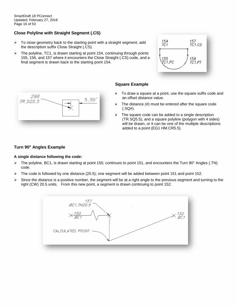
Close Polyline with Straight Segment (.CS) ➢ To close geometry back to the starting point with a straight segment, add
the description suffix Close Straight (.CS).
➢ The polyline, TC1, is drawn starting at point 154, continuing through points 155, 156, and 157 where it encounters the Close Straight (.CS) code, and a final segment is drawn back to the starting point 154.
Square Example ➢ To draw a square at a point, use the square suffix code and
an offset distance value.
➢ The distance (#) must be entered after the square code (.SQ#).
➢ The square code can be added to a single description (TR.SQ5.5), and a square polyline (polygon with 4 sides) will be drawn, or it can be one of the multiple descriptions added to a point (EG1 HM.CR5.5).
Turn 90° Angles Example A single distance following the code:
➢ The polyline, BC1, is drawn starting at point 150, continues to point 151, and encounters the Turn 90° Angles (.TN) code.
➢ The code is followed by one distance (20.5); one segment will be added between point 151 and point 152.
➢ Since the distance is a positive number, the segment will be at a right angle to the previous segment and turning to the right (CW) 20.5 units. From this new point, a segment is drawn continuing to point 152.
SmartDraft 18 PConnect Updated: February 27, 2018 Page 17 of 53
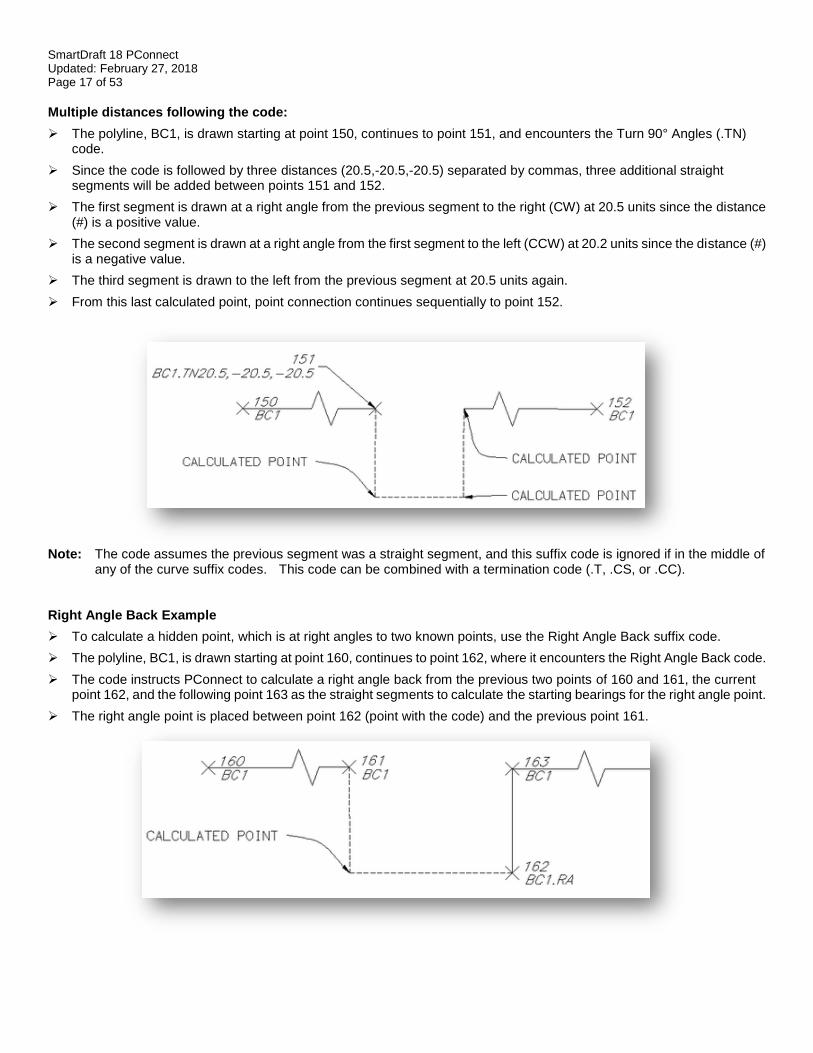
Multiple distances following the code:
➢ The polyline, BC1, is drawn starting at point 150, continues to point 151, and encounters the Turn 90° Angles (.TN) code.
➢ Since the code is followed by three distances (20.5,-20.5,-20.5) separated by commas, three additional straight segments will be added between points 151 and 152.
➢ The first segment is drawn at a right angle from the previous segment to the right (CW) at 20.5 units since the distance (#) is a positive value.
➢ The second segment is drawn at a right angle from the first segment to the left (CCW) at 20.2 units since the distance (#) is a negative value.
➢ The third segment is drawn to the left from the previous segment at 20.5 units again.
➢ From this last calculated point, point connection continues sequentially to point 152.
Note: The code assumes the previous segment was a straight segment, and this suffix code is ignored if in the middle of
any of the curve suffix codes. This code can be combined with a termination code (.T, .CS, or .CC). Right Angle Back Example
➢ To calculate a hidden point, which is at right angles to two known points, use the Right Angle Back suffix code.
➢ The polyline, BC1, is drawn starting at point 160, continues to point 162, where it encounters the Right Angle Back code.
➢ The code instructs PConnect to calculate a right angle back from the previous two points of 160 and 161, the current point 162, and the following point 163 as the straight segments to calculate the starting bearings for the right angle point.
➢ The right angle point is placed between point 162 (point with the code) and the previous point 161.
SmartDraft 18 PConnect Updated: February 27, 2018 Page 18 of 53
Note: This suffix code requires at least two prior points to calculate the starting angle and at least one point to calculate the ending angle. If there is no solution, parallel lines, or the calculated point is too far away, a straight line is drawn between the two points and a warning message is displayed at the end.
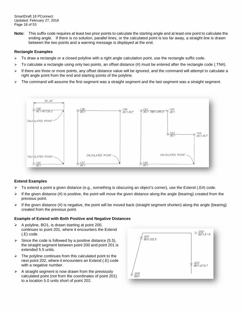
Rectangle Examples
➢ To draw a rectangle or a closed polyline with a right angle calculation point, use the rectangle suffix code.
➢ To calculate a rectangle using only two points, an offset distance (#) must be entered after the rectangle code (.TN#).
➢ If there are three or more points, any offset distance value will be ignored, and the command will attempt to calculate a right angle point from the end and starting points of the polyline.
➢ The command will assume the first segment was a straight segment and the last segment was a straight segment.
Extend Examples
➢ To extend a point a given distance (e.g., something is obscuring an object’s corner), use the Extend (.E#) code.
➢ If the given distance (#) is positive, the point will move the given distance along the angle (bearing) created from the previous point.
➢ If the given distance (#) is negative, the point will be moved back (straight segment shorten) along the angle (bearing) created from the previous point.
Example of Extend with Both Positive and Negative Distances
➢ A polyline, BO1, is drawn starting at point 200, continues to point 201, where it encounters the Extend (.E) code.
➢ Since the code is followed by a positive distance (5.5), the straight segment between point 200 and point 201 is extended 5.5 units.
➢ The polyline continues from this calculated point to the next point 202, where it encounters an Extend (.E) code with a negative number.
➢ A straight segment is now drawn from the previously calculated point (not from the coordinates of point 201) to a location 5.0 units short of point 202.
SmartDraft 18 PConnect Updated: February 27, 2018 Page 19 of 53
➢ The polyline continues from this point towards the next point 203, where it encounters a point with two codes, Extend (.E) and Terminate (.T).
➢ A straight segment is drawn from the previously calculated point toward 203, extends past it 10.0 units, and because of the Terminate (.T) code, B01 ends at this location.
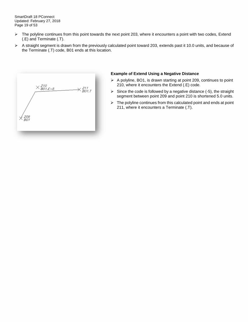
Example of Extend Using a Negative Distance
➢ A polyline, BO1, is drawn starting at point 209, continues to point 210, where it encounters the Extend (.E) code.
➢ Since the code is followed by a negative distance (-5), the straight segment between point 209 and point 210 is shortened 5.0 units.
➢ The polyline continues from this calculated point and ends at point 211, where it encounters a Terminate (.T).

SmartDraft 18 PConnect Updated: February 27, 2018 Page 20 of 53
PConnect Curve Examples Suffix Codes Examples for PConnect
Curve Suffix Codes: PConnect has multiple curve suffix codes: Begin Curve (.PC): This suffix code creates a tangent curve from the last segment. Tangent curves are calculated
between points until the End Curve (.PT) code, the last point, or a Terminate code (.T) is encountered.
3-Point Curve (.C3): This suffix code creates a non-tangent curve using three (3) points. It reads the next two points with the same description key. If only one point or the next point has the Terminate (.T) code, the calculation converts back to Begin Curve (.PC).
Best Fit Curve (.BC): This suffix code creates a Best Fit Curve with all the points that follow with the same description keys until the End Curve (.PT), the last point, or a Terminate code (.T) is encountered. The first curve may not be tangent to a proceeding straight or curve segment. If only one point follows the calculation converts back to Begin Curve (.PC).
Close Curved (.CC): This suffix code closes the current polyline back to the starting point with a tangent curve from the last segment.
Circle (.CR#) This suffix code draws a circle at the radius (#).
End Curve (.PT) This suffix code stops curve calculation and begins straight segments.
Examples of Using Curve Suffix Codes: Curve Example Using .PC (2-Point Tangent Curve)
➢ The polyline, EP1, is drawn starting at point 112 and continues to point 113 with the Begin Curve (.PC).
➢ A tangent curve is calculated from point 113 to point 114 from the bearing along point 112 to point 113.
➢ Curve segments are created between points 114 and 115, 115 and 116, 116 and 117, 117 and 118, and are all tangent to the proceeding curve segment.
➢ The End Curve (.PT) code is encountered at point 118, and a straight segment is drawn between points 118 and 119.
➢ The polyline ends at point 119.
Note: Field crews do not have to add a description suffix at a point of reverse or compound curve. As long as there is not
a straight segment, do not add the End Curve (.PT) code, and the command will draw the reverse or compound curve segments. PConnect checks for direction changes between segments and automatically determines the presence of a PRC or PCC, therefore, there is no need to identify the PRC or PCC with a PT/PC.
SmartDraft 18 PConnect Updated: February 27, 2018 Page 21 of 53
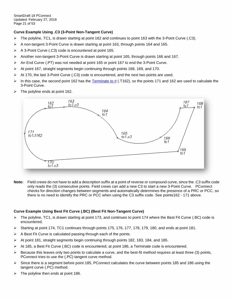
Curve Example Using .C3 (3-Point Non-Tangent Curve)
➢ The polyline, TC1, is drawn starting at point 162 and continues to point 163 with the 3-Point Curve (.C3).
➢ A non-tangent 3-Point Curve is drawn starting at point 163, through points 164 and 165.
➢ A 3-Point Curve (.C3) code is encountered at point 165.
➢ Another non-tangent 3-Point Curve is drawn starting at point 165, through points 166 and 167.
➢ An End Curve (.PT) was not needed at point 165 or point 167 to end the 3-Point Curve.
➢ At point 167, straight segments begin continuing through points 168, 169, and 170.
➢ At 170, the last 3-Point Curve (.C3) code is encountered, and the next two points are used.
➢ In this case, the second point 162 has the Terminate to # (.T162), so the points 171 and 162 are used to calculate the 3-Point Curve.
➢ The polyline ends at point 162.
Note: Field crews do not have to add a description suffix at a point of reverse or compound curve, since the .C3 suffix code
only reads the (3) consecutive points. Field crews can add a new C3 to start a new 3-Point Curve. PConnect checks for direction changes between segments and automatically determines the presence of a PRC or PCC, so there is no need to identify the PRC or PCC when using the C3 suffix code. See points162 - 171 above.
Curve Example Using Best Fit Curve (.BC) (Best Fit Non-Tangent Curve)
➢ The polyline, TC1, is drawn starting at point 173, and continues to point 174 where the Best Fit Curve (.BC) code is encountered.
➢ Starting at point 174, TC1 continues through points 175, 176, 177, 178, 179, 180, and ends at point 181.
➢ A Best Fit Curve is calculated passing through each of the points.
➢ At point 181, straight segments begin continuing through points 182, 183, 184, and 185.
➢ At 185, a Best Fit Curve (.BC) code is encountered; at point 186, a Terminate code is encountered.
➢ Because this leaves only two points to calculate a curve, and the best-fit method requires at least three (3) points, PConnect tries to use the (.PC) tangent curve method.
➢ Since there is a segment before point 185, PConnect calculates the curve between points 185 and 186 using the tangent curve (.PC) method.
➢ The polyline then ends at point 186.
SmartDraft 18 PConnect Updated: February 27, 2018 Page 22 of 53
Note: If only two points are encountered after the Best Fit Curve (.BC) code, and the bearings created between the first
two points and the second two points differ by less than five (5) degrees, the Begin Curve (.PC) calculation method is used to create a reverse curve. If the Best Fit Curve method was used, the curved segments would appear almost like two straight segments.
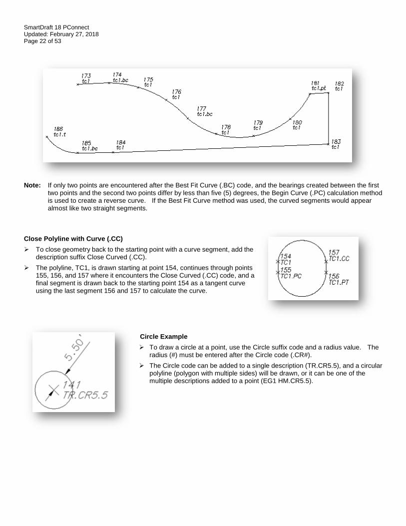
Close Polyline with Curve (.CC)
➢ To close geometry back to the starting point with a curve segment, add the description suffix Close Curved (.CC).
➢ The polyline, TC1, is drawn starting at point 154, continues through points 155, 156, and 157 where it encounters the Close Curved (.CC) code, and a final segment is drawn back to the starting point 154 as a tangent curve using the last segment 156 and 157 to calculate the curve.
Circle Example
➢ To draw a circle at a point, use the Circle suffix code and a radius value. The radius (#) must be entered after the Circle code (.CR#).
➢ The Circle code can be added to a single description (TR.CR5.5), and a circular polyline (polygon with multiple sides) will be drawn, or it can be one of the multiple descriptions added to a point (EG1 HM.CR5.5).
SmartDraft 18 PConnect Updated: February 27, 2018 Page 23 of 53
PConnect Offset Examples Suffix Codes Examples for PConnect ➢ The Offset (.O#) code is used to offset polylines to either the right, with a positive distance (#), or to the left, with a
negative distance (#). ➢ The Offset code is terminated by Offset Terminate (.OT), another Offset, a Middle, or a Template code. ➢ The Offset, Middle, or Template suffix codes cannot be combined. ➢ The Offset code can be associated to the first (primary) description or any of the descriptions when using multiple
descriptions assigned to a single point. ➢ When it is not the primary description key, the offset follows the primary description for the path but uses the offset
description for the layer and any Elevation on Offset adjustment.
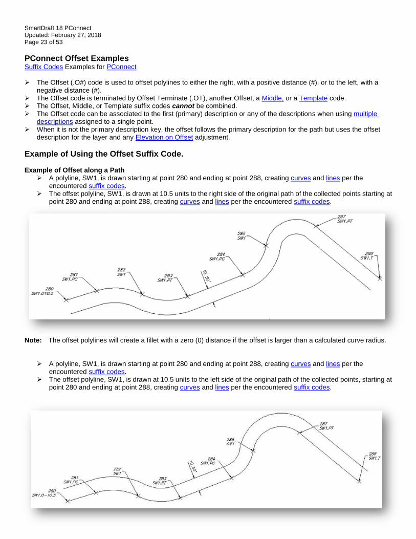
Example of Using the Offset Suffix Code. Example of Offset along a Path
➢ A polyline, SW1, is drawn starting at point 280 and ending at point 288, creating curves and lines per the encountered suffix codes.
➢ The offset polyline, SW1, is drawn at 10.5 units to the right side of the original path of the collected points starting at point 280 and ending at point 288, creating curves and lines per the encountered suffix codes.
Note: The offset polylines will create a fillet with a zero (0) distance if the offset is larger than a calculated curve radius.
➢ A polyline, SW1, is drawn starting at point 280 and ending at point 288, creating curves and lines per the encountered suffix codes.
➢ The offset polyline, SW1, is drawn at 10.5 units to the left side of the original path of the collected points, starting at point 280 and ending at point 288, creating curves and lines per the encountered suffix codes.
SmartDraft 18 PConnect Updated: February 27, 2018 Page 24 of 53
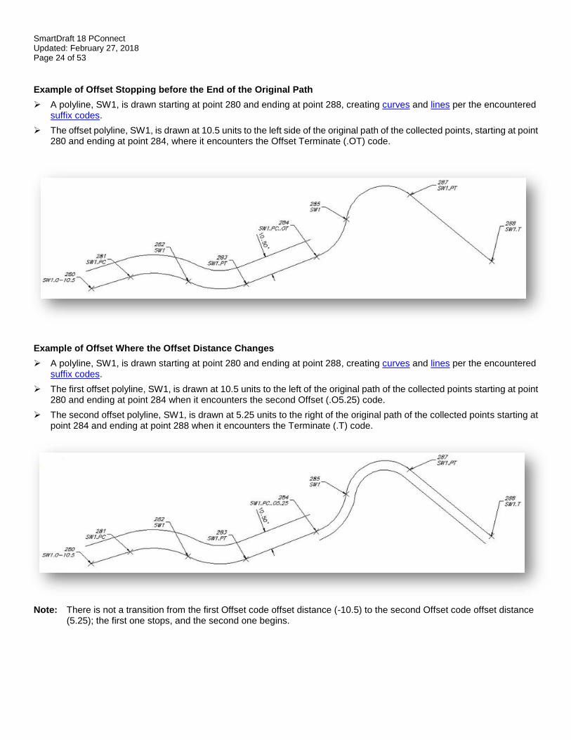
Example of Offset Stopping before the End of the Original Path
➢ A polyline, SW1, is drawn starting at point 280 and ending at point 288, creating curves and lines per the encountered suffix codes.
➢ The offset polyline, SW1, is drawn at 10.5 units to the left side of the original path of the collected points, starting at point 280 and ending at point 284, where it encounters the Offset Terminate (.OT) code.
Example of Offset Where the Offset Distance Changes
➢ A polyline, SW1, is drawn starting at point 280 and ending at point 288, creating curves and lines per the encountered suffix codes.
➢ The first offset polyline, SW1, is drawn at 10.5 units to the left of the original path of the collected points starting at point 280 and ending at point 284 when it encounters the second Offset (.O5.25) code.
➢ The second offset polyline, SW1, is drawn at 5.25 units to the right of the original path of the collected points starting at point 284 and ending at point 288 when it encounters the Terminate (.T) code.
Note: There is not a transition from the first Offset code offset distance (-10.5) to the second Offset code offset distance (5.25); the first one stops, and the second one begins.
SmartDraft 18 PConnect Updated: February 27, 2018 Page 25 of 53
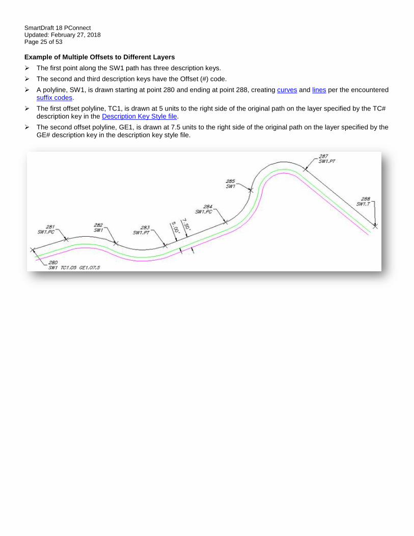
Example of Multiple Offsets to Different Layers
➢ The first point along the SW1 path has three description keys.
➢ The second and third description keys have the Offset (#) code.
➢ A polyline, SW1, is drawn starting at point 280 and ending at point 288, creating curves and lines per the encountered suffix codes.
➢ The first offset polyline, TC1, is drawn at 5 units to the right side of the original path on the layer specified by the TC# description key in the Description Key Style file.
➢ The second offset polyline, GE1, is drawn at 7.5 units to the right side of the original path on the layer specified by the GE# description key in the description key style file.
SmartDraft 18 PConnect Updated: February 27, 2018 Page 26 of 53
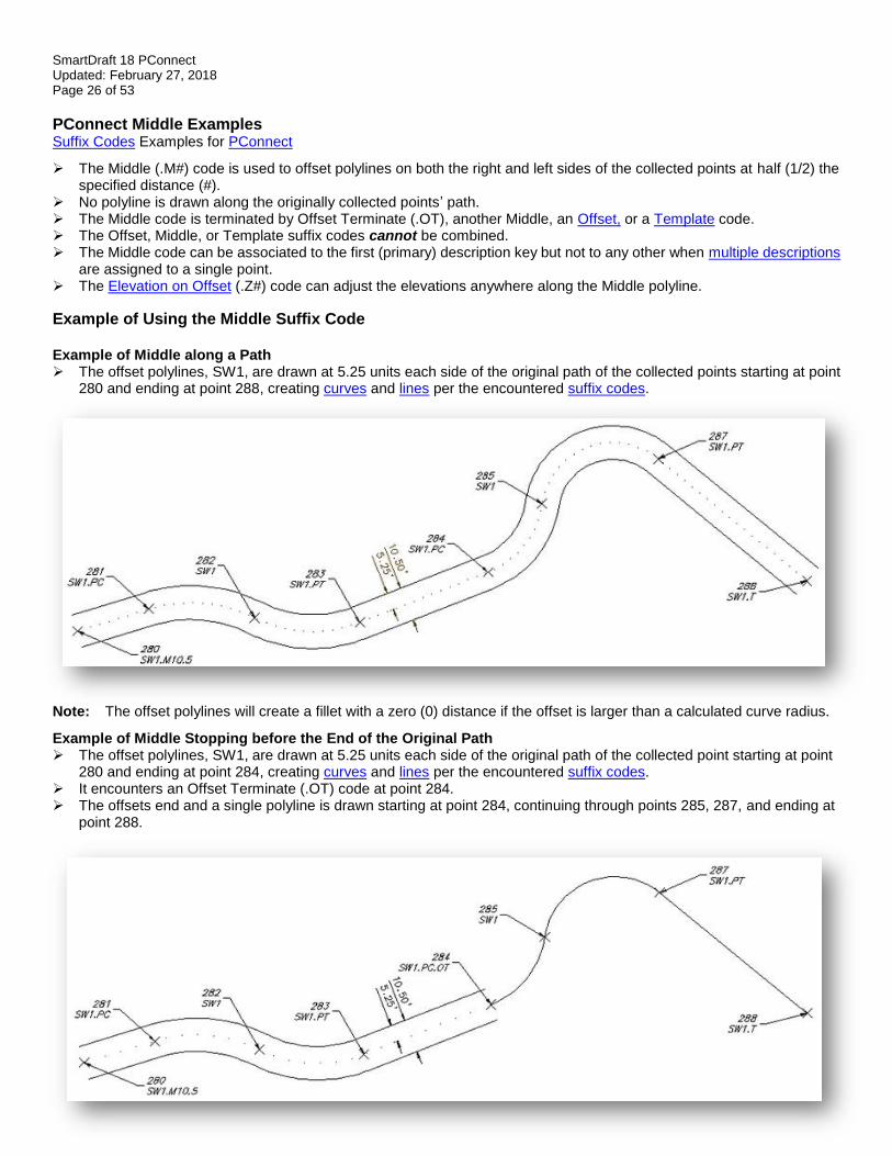
PConnect Middle Examples Suffix Codes Examples for PConnect
➢ The Middle (.M#) code is used to offset polylines on both the right and left sides of the collected points at half (1/2) the specified distance (#).
➢ No polyline is drawn along the originally collected points’ path. ➢ The Middle code is terminated by Offset Terminate (.OT), another Middle, an Offset, or a Template code. ➢ The Offset, Middle, or Template suffix codes cannot be combined. ➢ The Middle code can be associated to the first (primary) description key but not to any other when multiple descriptions
are assigned to a single point. ➢ The Elevation on Offset (.Z#) code can adjust the elevations anywhere along the Middle polyline.
Example of Using the Middle Suffix Code Example of Middle along a Path ➢ The offset polylines, SW1, are drawn at 5.25 units each side of the original path of the collected points starting at point
280 and ending at point 288, creating curves and lines per the encountered suffix codes.
Note: The offset polylines will create a fillet with a zero (0) distance if the offset is larger than a calculated curve radius.
Example of Middle Stopping before the End of the Original Path ➢ The offset polylines, SW1, are drawn at 5.25 units each side of the original path of the collected point starting at point
280 and ending at point 284, creating curves and lines per the encountered suffix codes. ➢ It encounters an Offset Terminate (.OT) code at point 284. ➢ The offsets end and a single polyline is drawn starting at point 284, continuing through points 285, 287, and ending at
point 288.
SmartDraft 18 PConnect Updated: February 27, 2018 Page 27 of 53
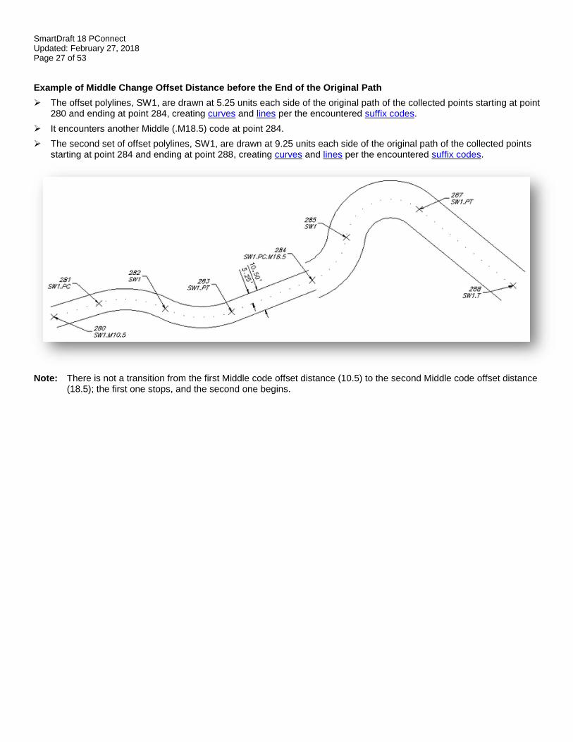
Example of Middle Change Offset Distance before the End of the Original Path
➢ The offset polylines, SW1, are drawn at 5.25 units each side of the original path of the collected points starting at point 280 and ending at point 284, creating curves and lines per the encountered suffix codes.
➢ It encounters another Middle (.M18.5) code at point 284.
➢ The second set of offset polylines, SW1, are drawn at 9.25 units each side of the original path of the collected points starting at point 284 and ending at point 288, creating curves and lines per the encountered suffix codes.
Note: There is not a transition from the first Middle code offset distance (10.5) to the second Middle code offset distance (18.5); the first one stops, and the second one begins.
SmartDraft 18 PConnect Updated: February 27, 2018 Page 28 of 53
PConnect Template Examples Suffix Codes Examples for PConnect:
The Template code is for collecting a single point along a feature in the field which follows a specific pattern of offsets and heights.
➢ The Template code (.ZT#) can be used to offset polylines on both the right and left sides multiple times and with elevation adjustments.
➢ The template name (#) specifies the template file to be used.
➢ Add the template name (#) to the Template code (.ZT#) to start using a template.
➢ If the template is to be mirrored, add the "-" negative character before the template name (e.g., .ZT-CB1).
➢ The Template Terminate code (.ZT) is the Template code without a template name. Using this code ends the offsets started in a template.
➢ The Template code is terminated by Offset Terminate (.OT), another Template, a Middle, or an Offset code. The Offset, Middle, or Template suffix codes cannot be combined.
➢ The Template code can be associated to the first (primary) description but not to any other when multiple descriptions are assigned to a single point.
➢ The Elevation on Offset (.Z#) code can replace the elevation of the first segment to the right or left (as defined in the template) of the field shot point.
➢ Templates are created and modified with the PConnect Template Manager.
Example of Using the Template Suffix Code
Example of a Template along a Path
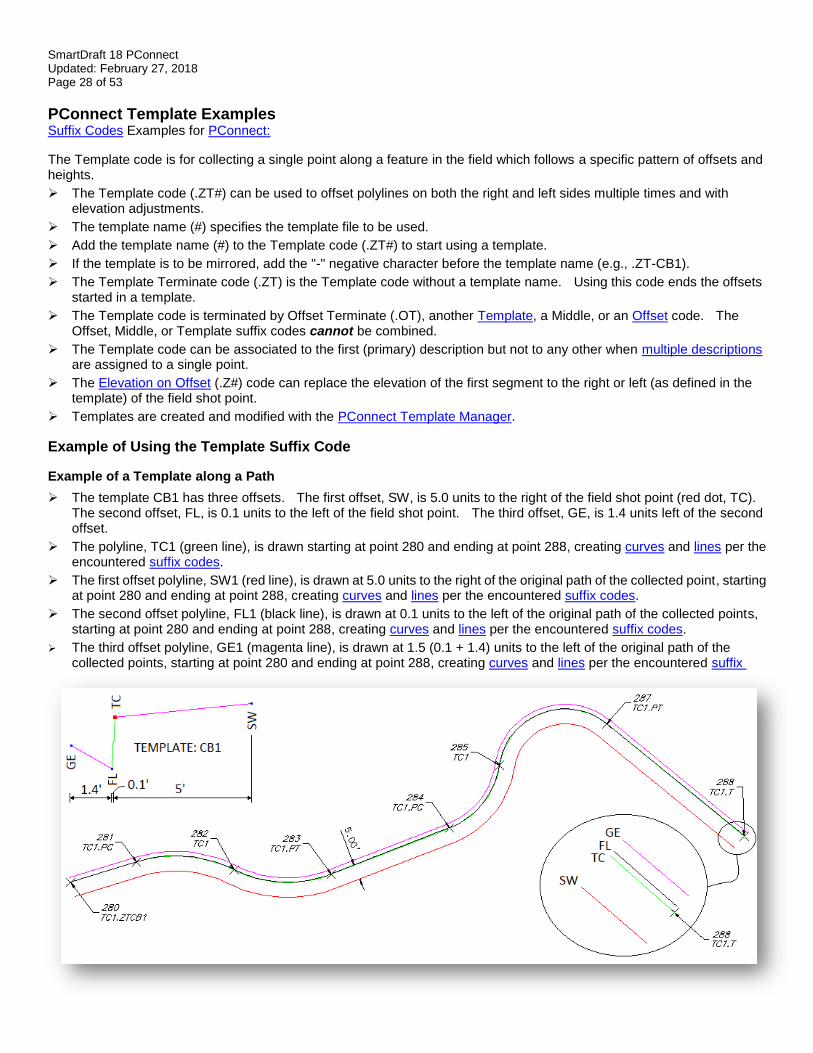
➢ The template CB1 has three offsets. The first offset, SW, is 5.0 units to the right of the field shot point (red dot, TC). The second offset, FL, is 0.1 units to the left of the field shot point. The third offset, GE, is 1.4 units left of the second offset.
➢ The polyline, TC1 (green line), is drawn starting at point 280 and ending at point 288, creating curves and lines per the encountered suffix codes.
➢ The first offset polyline, SW1 (red line), is drawn at 5.0 units to the right of the original path of the collected point, starting at point 280 and ending at point 288, creating curves and lines per the encountered suffix codes.
➢ The second offset polyline, FL1 (black line), is drawn at 0.1 units to the left of the original path of the collected points, starting at point 280 and ending at point 288, creating curves and lines per the encountered suffix codes.
➢ The third offset polyline, GE1 (magenta line), is drawn at 1.5 (0.1 + 1.4) units to the left of the original path of the collected points, starting at point 280 and ending at point 288, creating curves and lines per the encountered suffix
SmartDraft 18 PConnect Updated: February 27, 2018 Page 29 of 53
codes. Note: The offset polylines will create a fillet with a zero (0) distance if the offset is larger than a calculated curve radius.
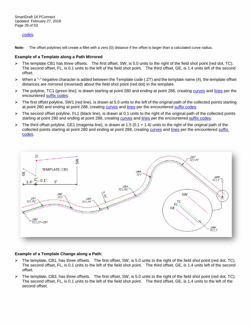
Example of a Template along a Path Mirrored
➢ The template CB1 has three offsets. The first offset, SW, is 5.0 units to the right of the field shot point (red dot, TC). The second offset, FL, is 0.1 units to the left of the field shot point. The third offset, GE, is 1.4 units left of the second offset.
➢ When a "-" negative character is added between the Template code (.ZT) and the template name (#), the template offset distances are mirrored (reversed) about the field shot point (red dot) in the template.
➢ The polyline, TC1 (green line), is drawn starting at point 280 and ending at point 288, creating curves and lines per the encountered suffix codes.
➢ The first offset polyline, SW1 (red line), is drawn at 5.0 units to the left of the original path of the collected points starting at point 280 and ending at point 288, creating curves and lines per the encountered suffix codes.
➢ The second offset polyline, FL1 (black line), is drawn at 0.1 units to the right of the original path of the collected points starting at point 280 and ending at point 288, creating curves and lines per the encountered suffix codes.
➢ The third offset polyline, GE1 (magenta line), is drawn at 1.5 (0.1 + 1.4) units to the right of the original path of the collected points starting at point 280 and ending at point 288, creating curves and lines per the encountered suffix codes.
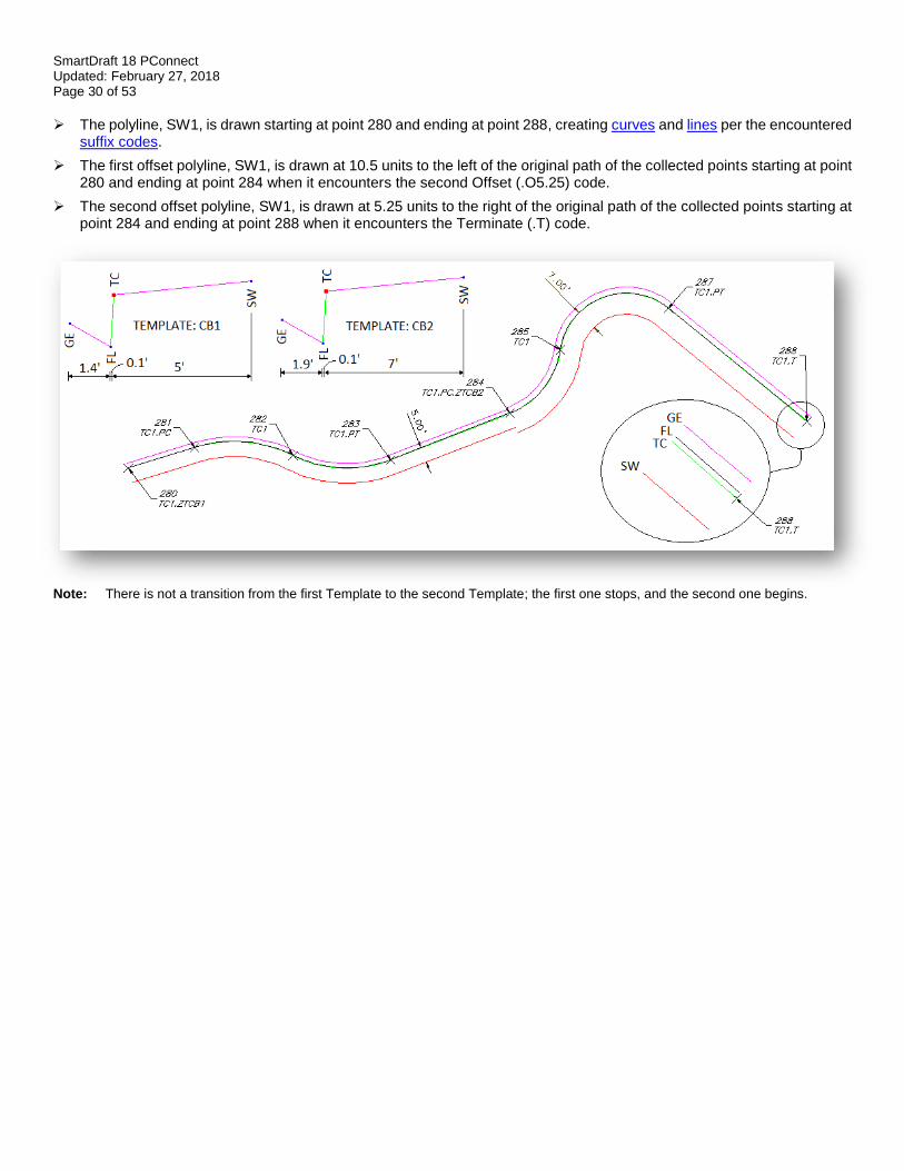
Example of a Template Change along a Path:
➢ The template, CB1, has three offsets. The first offset, SW, is 5.0 units to the right of the field shot point (red dot, TC). The second offset, FL, is 0.1 units to the left of the field shot point. The third offset, GE, is 1.4 units left of the second offset.
➢ The template, CB3, has three offsets. The first offset, SW, is 5.0 units to the right of the field shot point (red dot, TC). The second offset, FL, is 0.1 units to the left of the field shot point. The third offset, GE, is 1.4 units to the left of the second offset.
SmartDraft 18 PConnect Updated: February 27, 2018 Page 30 of 53
➢ The polyline, SW1, is drawn starting at point 280 and ending at point 288, creating curves and lines per the encountered suffix codes.
➢ The first offset polyline, SW1, is drawn at 10.5 units to the left of the original path of the collected points starting at point 280 and ending at point 284 when it encounters the second Offset (.O5.25) code.
➢ The second offset polyline, SW1, is drawn at 5.25 units to the right of the original path of the collected points starting at point 284 and ending at point 288 when it encounters the Terminate (.T) code.
Note: There is not a transition from the first Template to the second Template; the first one stops, and the second one begins.
SmartDraft 18 PConnect Updated: February 27, 2018 Page 31 of 53
PConnect Elevation on Offsets Examples Suffix Codes Examples for PConnect
This code only applies to PConnect Draw Options: 3D Polyline and Civil 3D Survey Figures.
➢ The Elevation on Offset (.Z#) code does not adjust the elevation on individual points or elevations along the original path of a polyline.
➢ The Elevation on Offset (.Z#) code adjusts the elevation of the offset and middle offset polylines.
➢ If the Elevation on Offset (.Z) code is used without an adjustment number (#), the elevations are not adjusted from this point forward.
➢ The Elevation on Offset (.Z#) code replaces the first height value specified in a PConnect Template.
➢ If the Elevation on Offset (.Z) code is used without an adjustment number (#) when a template is active, the replaced height returns to the height specified in the template.
Example of Using the Elevation on Offsets Suffix Code
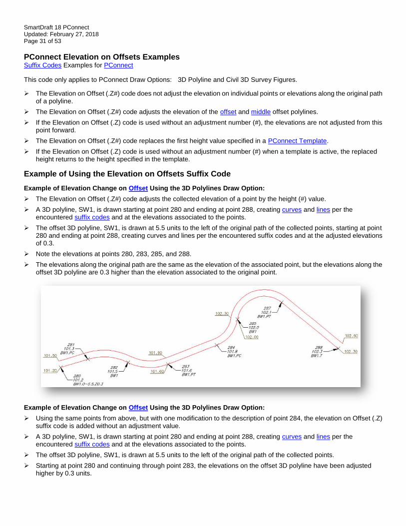
Example of Elevation Change on Offset Using the 3D Polylines Draw Option:
➢ The Elevation on Offset (.Z#) code adjusts the collected elevation of a point by the height (#) value.
➢ A 3D polyline, SW1, is drawn starting at point 280 and ending at point 288, creating curves and lines per the encountered suffix codes and at the elevations associated to the points.
➢ The offset 3D polyline, SW1, is drawn at 5.5 units to the left of the original path of the collected points, starting at point 280 and ending at point 288, creating curves and lines per the encountered suffix codes and at the adjusted elevations of 0.3.
➢ Note the elevations at points 280, 283, 285, and 288.
➢ The elevations along the original path are the same as the elevation of the associated point, but the elevations along the offset 3D polyline are 0.3 higher than the elevation associated to the original point.
Example of Elevation Change on Offset Using the 3D Polylines Draw Option:
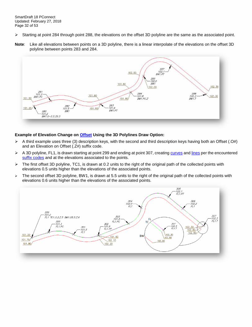
➢ Using the same points from above, but with one modification to the description of point 284, the elevation on Offset (.Z) suffix code is added without an adjustment value.
➢ A 3D polyline, SW1, is drawn starting at point 280 and ending at point 288, creating curves and lines per the encountered suffix codes and at the elevations associated to the points.
➢ The offset 3D polyline, SW1, is drawn at 5.5 units to the left of the original path of the collected points.
➢ Starting at point 280 and continuing through point 283, the elevations on the offset 3D polyline have been adjusted higher by 0.3 units.
SmartDraft 18 PConnect Updated: February 27, 2018 Page 32 of 53
➢ Starting at point 284 through point 288, the elevations on the offset 3D polyline are the same as the associated point. Note: Like all elevations between points on a 3D polyline, there is a linear interpolate of the elevations on the offset 3D polyline between points 283 and 284.
Example of Elevation Change on Offset Using the 3D Polylines Draw Option:
➢ A third example uses three (3) description keys, with the second and third description keys having both an Offset (.O#) and an Elevation on Offset (.Z#) suffix code.
➢ A 3D polyline, FL1, is drawn starting at point 299 and ending at point 307, creating curves and lines per the encountered suffix codes and at the elevations associated to the points.
➢ The first offset 3D polyline, TC1, is drawn at 0.2 units to the right of the original path of the collected points with elevations 0.5 units higher than the elevations of the associated points.
➢ The second offset 3D polyline, BW1, is drawn at 5.5 units to the right of the original path of the collected points with elevations 0.6 units higher than the elevations of the associated points.
SmartDraft 18 PConnect Updated: February 27, 2018 Page 33 of 53
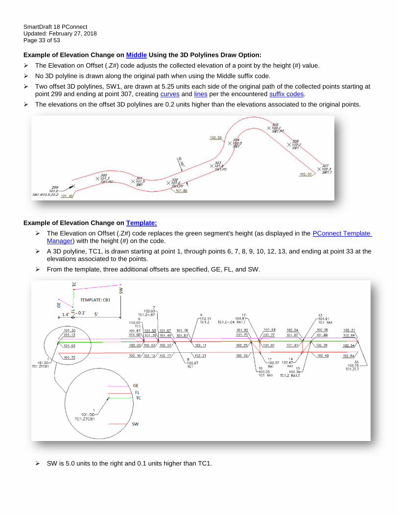
Example of Elevation Change on Middle Using the 3D Polylines Draw Option:
➢ The Elevation on Offset (.Z#) code adjusts the collected elevation of a point by the height (#) value.
➢ No 3D polyline is drawn along the original path when using the Middle suffix code.
➢ Two offset 3D polylines, SW1, are drawn at 5.25 units each side of the original path of the collected points starting at point 299 and ending at point 307, creating curves and lines per the encountered suffix codes.
➢ The elevations on the offset 3D polylines are 0.2 units higher than the elevations associated to the original points.
Example of Elevation Change on Template:
➢ The Elevation on Offset (.Z#) code replaces the green segment's height (as displayed in the PConnect Template Manager) with the height (#) on the code.
➢ A 3D polyline, TC1, is drawn starting at point 1, through points 6, 7, 8, 9, 10, 12, 13, and ending at point 33 at the elevations associated to the points.
➢ From the template, three additional offsets are specified, GE, FL, and SW.
➢ SW is 5.0 units to the right and 0.1 units higher than TC1.
SmartDraft 18 PConnect Updated: February 27, 2018 Page 34 of 53
➢ FL is 0.1 units to the left and 0.5 units lower than TC1.
➢ GE is 1.4 units to the left and 0.17 units higher than FL.
➢ At point 7, notice the Elevation on Offset (.Z-.67). The -0.5 height defined in the template (green segment) will be replaced with -0.67, due to a curb inlet, and will continue through point 8.
➢ At point 9, notice the Elevation on Offset (.Z) without a value. The temporary height of -0.67 for the green segment returns to the defined height of -0.5.
➢ Compared to the associated elevations of TC1, the 3D polylines drawn along the FL between points 6 and 7 transition from -0.5 at point 6 to -0.67 at point 7 and transition between points 8 and 9 from -0.67 to -0.05.
➢ At point 10, notice the two description keys, TC1 and RA1. A 3D polyline drawn along RA starts at point 10, continues through point 11, and ends at point 12, which also has two description keys, TC1 and RA1.T.
➢ At point 12, notice the Elevation on Offset (.Z-.04). The -0.5 height defined in the template (green segment) will be replaced with -0.04, due to a driveway, and will continue through point 14.
➢ At point 15, notice the Elevation on Offset (.Z) without a value. The temporary height of -0.04 for the green segment returns to the defined height of -0.5.
➢ The 3D polylines drawn along the FL between points 10 and 12 transition from -0.5 at point 10 to -0.04 at point 12, relative to the associated elevations, and transition between points 13 and 14 from -0.04 to -0.05.
➢ The elevations on the offset 3D polylines, SW, are 0.1 higher than the elevations associated to the original points.
SmartDraft 18 PConnect Updated: February 27, 2018 Page 35 of 53
PConnect Terminate and Recall Examples Suffix Codes Examples for PConnect: ➢ The Terminate suffix code ends a polyline / survey figure drawn along the same description key code, i.e., EC1.
➢ The Terminate suffix code also terminates offsets, middles, and templates.
➢ There are two types of Terminate suffix codes; one without a point number following the code (.T) and one with a point number (.T100) following it.
➢ When a point number is added to the Terminate code, the polyline ends at the coordinate value of the point number.
➢ PConnect normally processes points in ascending point number order.
➢ Using a point number after the Terminate suffix code allows the polyline to end on a coordinate with a lower point number than the current point number.
➢ The Terminate suffix code can be combined with the Turn 90 Degree Angles (.TN), Extend (.E), Square (.SQ), and Circle (.CR) codes.
➢ The Terminate to point number (#) suffix code can be combined with the Begin Curve (.PC) , End Curve (.PT), Right Angle Back (.RA), Turn 90 Degree Angle (.TN), Extend (.E), and can be used on the point just following the 3-point curve (.C3).
Example of Using the Terminate Suffix Code
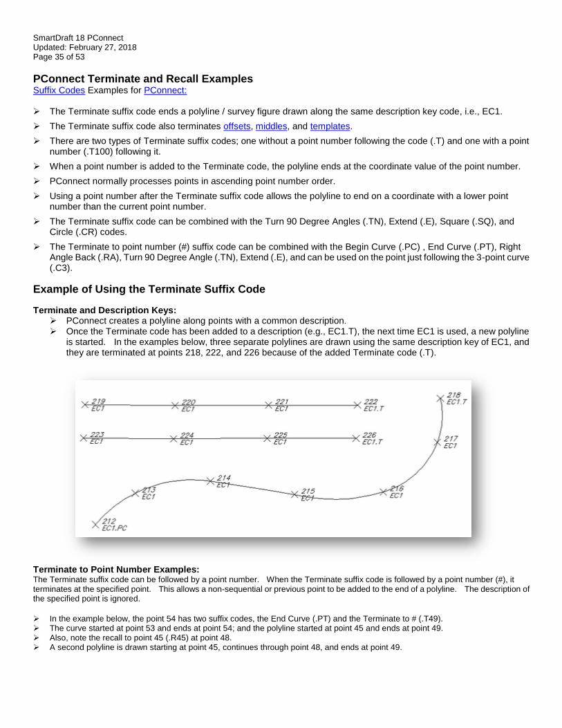
Terminate and Description Keys: ➢ PConnect creates a polyline along points with a common description. ➢ Once the Terminate code has been added to a description (e.g., EC1.T), the next time EC1 is used, a new polyline
is started. In the examples below, three separate polylines are drawn using the same description key of EC1, and they are terminated at points 218, 222, and 226 because of the added Terminate code (.T).
Terminate to Point Number Examples: The Terminate suffix code can be followed by a point number. When the Terminate suffix code is followed by a point number (#), it terminates at the specified point. This allows a non-sequential or previous point to be added to the end of a polyline. The description of the specified point is ignored.
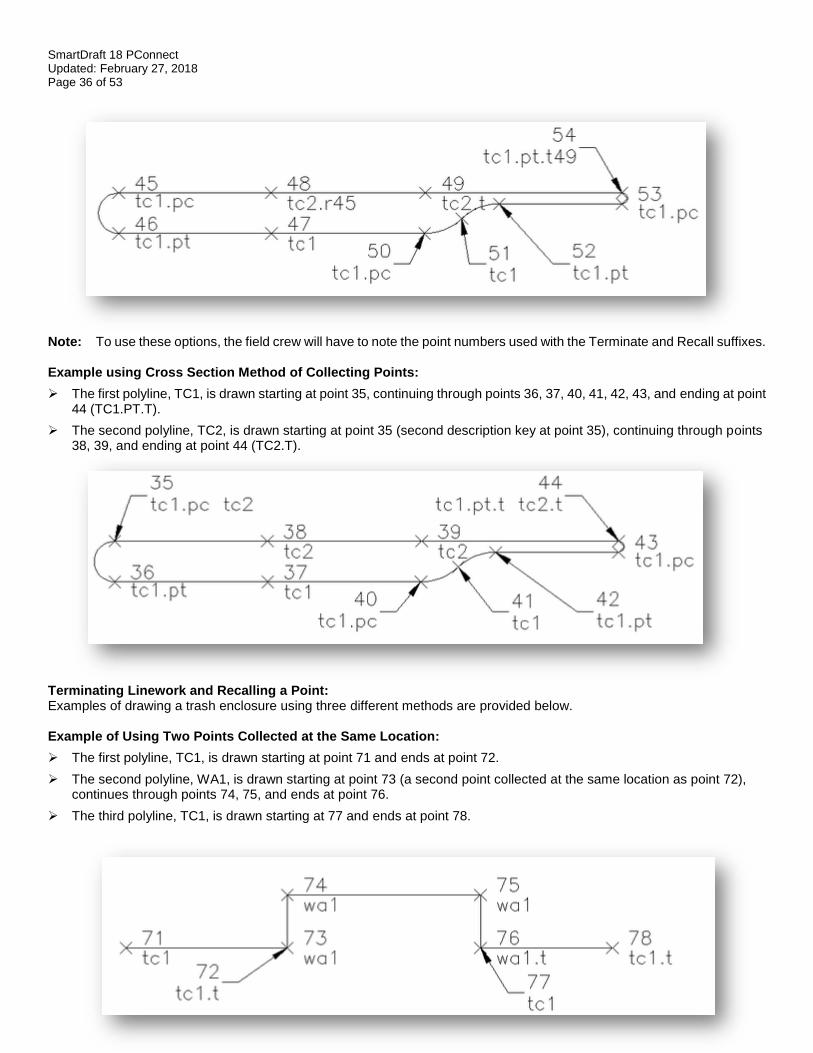
➢ In the example below, the point 54 has two suffix codes, the End Curve (.PT) and the Terminate to # (.T49). ➢ The curve started at point 53 and ends at point 54; and the polyline started at point 45 and ends at point 49. ➢ Also, note the recall to point 45 (.R45) at point 48. ➢ A second polyline is drawn starting at point 45, continues through point 48, and ends at point 49.
SmartDraft 18 PConnect Updated: February 27, 2018 Page 36 of 53
Note: To use these options, the field crew will have to note the point numbers used with the Terminate and Recall suffixes. Example using Cross Section Method of Collecting Points:
➢ The first polyline, TC1, is drawn starting at point 35, continuing through points 36, 37, 40, 41, 42, 43, and ending at point 44 (TC1.PT.T).
➢ The second polyline, TC2, is drawn starting at point 35 (second description key at point 35), continuing through points 38, 39, and ending at point 44 (TC2.T).
Terminating Linework and Recalling a Point: Examples of drawing a trash enclosure using three different methods are provided below. Example of Using Two Points Collected at the Same Location:
➢ The first polyline, TC1, is drawn starting at point 71 and ends at point 72.
➢ The second polyline, WA1, is drawn starting at point 73 (a second point collected at the same location as point 72), continues through points 74, 75, and ends at point 76.
➢ The third polyline, TC1, is drawn starting at 77 and ends at point 78.
SmartDraft 18 PConnect Updated: February 27, 2018 Page 37 of 53
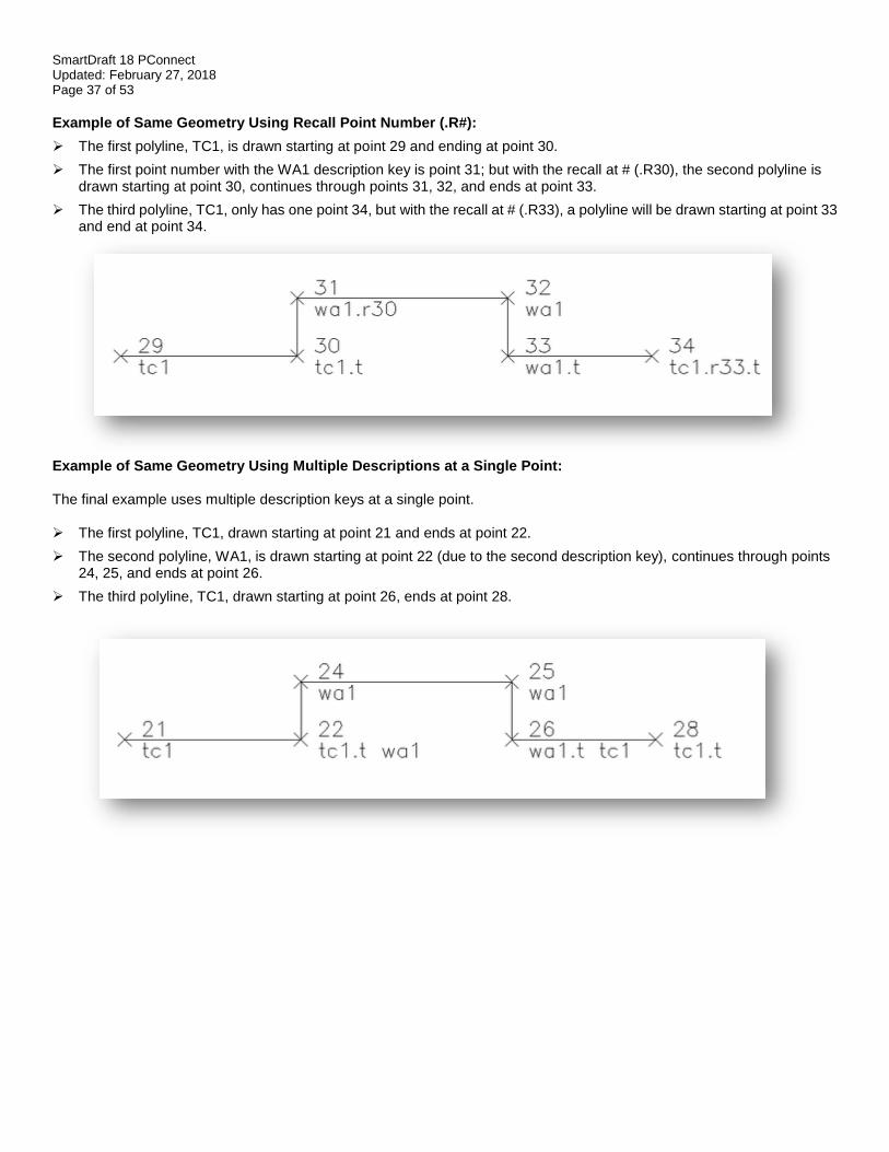
Example of Same Geometry Using Recall Point Number (.R#):
➢ The first polyline, TC1, is drawn starting at point 29 and ending at point 30.
➢ The first point number with the WA1 description key is point 31; but with the recall at # (.R30), the second polyline is drawn starting at point 30, continues through points 31, 32, and ends at point 33.
➢ The third polyline, TC1, only has one point 34, but with the recall at # (.R33), a polyline will be drawn starting at point 33 and end at point 34.
Example of Same Geometry Using Multiple Descriptions at a Single Point: The final example uses multiple description keys at a single point. ➢ The first polyline, TC1, drawn starting at point 21 and ends at point 22.
➢ The second polyline, WA1, is drawn starting at point 22 (due to the second description key), continues through points 24, 25, and ends at point 26.
➢ The third polyline, TC1, drawn starting at point 26, ends at point 28.
SmartDraft 18 PConnect Updated: February 27, 2018 Page 38 of 53
PConnect Multiple Description Keys Examples Suffix Codes Examples for PConnect
➢ PConnect allows the field crew to assign multiple description keys to the same field point.
➢ A space is required between each description to separate them and indicate to PConnect that there are multiple descriptions.
➢ Each description key can also have a separate suffix code or no suffix code.
Multiple Description Key Examples
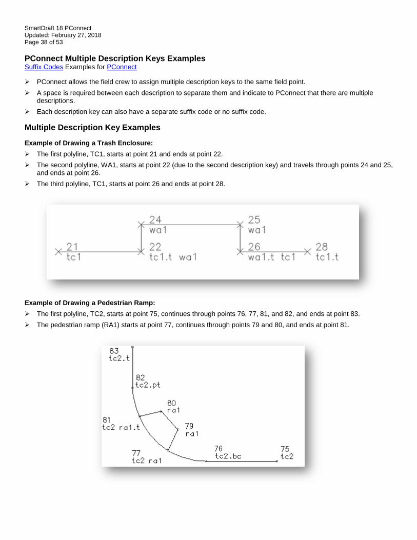
Example of Drawing a Trash Enclosure:
➢ The first polyline, TC1, starts at point 21 and ends at point 22.
➢ The second polyline, WA1, starts at point 22 (due to the second description key) and travels through points 24 and 25, and ends at point 26.
➢ The third polyline, TC1, starts at point 26 and ends at point 28.
Example of Drawing a Pedestrian Ramp:
➢ The first polyline, TC2, starts at point 75, continues through points 76, 77, 81, and 82, and ends at point 83.
➢ The pedestrian ramp (RA1) starts at point 77, continues through points 79 and 80, and ends at point 81.
SmartDraft 18 PConnect Updated: February 27, 2018 Page 39 of 53
PConnect Cross-Section Examples Suffix Codes Examples for PConnect ➢ PConnect allows the field crew to collect common features in the cross-section method of data collection. ➢ The field crew must use a unique description key with a different index number (#) to identify each feature. ➢ Once a Terminate (.T), Rectangle (.RCT), Close Straight (.CS), or Close Curved (.CC) code is encountered, the same
description and index number (#) can be used again. ➢ Example: TC1 for Top-of Curb on the left and TC2 for Top-of-Curb on the right.
Cross-Section Data Collection Examples
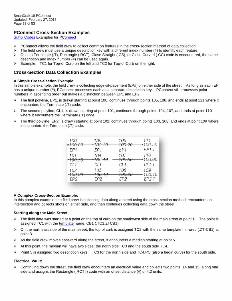
A Simple Cross-Section Example: In this simple example, the field crew is collecting edge-of-pavement (EP#) on either side of the street. As long as each EP has a unique number (#), PConnect processes each as a separate description key. PConnect still processes point numbers in ascending order but makes a distinction between EP1 and EP2.
➢ The first polyline, EP1, is drawn starting at point 100, continues through points 105, 106, and ends at point 111 where it encounters the Terminate (.T) code.
➢ The second polyline, CL1, is drawn starting at point 101, continues through points 104, 107, and ends at point 110 where it encounters the Terminate (.T) code.
➢ The third polyline, EP2, is drawn starting at point 102, continues through points 103, 108, and ends at point 109 where it encounters the Terminate (.T) code.
A Complex Cross-Section Example: In this complex example, the field crew is collecting data along a street using the cross-section method, encounters an intersection and collects shots on either side, and then continues collecting data down the street. Starting along the Main Street:
➢ The field data was started at a point on the top of curb on the southwest side of the main street at point 1. The point is assigned TC1 with the template name, CB1 (.TC1.ZTCB1).
➢ On the northeast side of the main street, the top of curb is assigned TC2 with the same template mirrored (.ZT-CB1) at point 3.
➢ As the field crew moves eastward along the street, it encounters a median starting at point 5.
➢ At this point, the median will have two sides: the north side TC3 and the south side TC4.
➢ Point 5 is assigned two description keys: TC3 for the north side and TC4.PC (also a begin curve) for the south side. Electrical Vault:
➢ Continuing down the street, the field crew encounters an electrical value and collects two points, 14 and 15, along one side and assigns the Rectangle (.RCT#) code with an offset distance (#) of 4.2 units.
SmartDraft 18 PConnect Updated: February 27, 2018 Page 40 of 53
➢ This draws a rectangular polyline that is 4.2 units wide.
➢ At point 19, the field crew assigns the Begin Curve (.PC) code to draw the turn lane. Coming to the Intersection:
➢ As the field crew nears the intersection, on the north side of the street, the Terminate Template (.ZT) code is assigned to point 27.
➢ To complete the median, the crew assigns both the Begin Curve (.PT) and Terminate to P# (.T#) codes to point 29 (TC3).
➢ Since the crew knows the next point will be 30, it assigns the Terminate to P# (.T30) code to point 29.
➢ When the crew collects point 30, it assigns the description key TC4 with the Terminate (.T) code.
➢ The south side of the median curb (TC4) starts at point 5, continues through points 7, 10, 19, 22, 24, and ends at point 30 with the Terminate code.
➢ The north side of the median curb (TC3) also starts at point 5, continues through points 12, 17, 25, 29, and ends at point 30.
➢ On the south side of the street, the template running along TC1 is terminated at point 33 using the Template Terminate (.ZT) code.
Southwest Corner Curb Return:
➢ Since the template stops at point 33, to draw the back of the sidewalk line around the curb return, the field crew starts at point 34 and continues through points 35, 36, 37, 44, 45, and ends at 46 with a Terminate (.T) code.
➢ In the middle of collecting the WB1 line, the crew collects point 38 with both a TC1 (to continue the TC1 into a curve around the curb return at starting point 33) and RA1 (ramp), a second RA2 ramp line is shot at point 39, with both RA1 and RA2 going to point 40, and RA2 terminates at this point.
➢ RA1 continues to point 41, and RA3 is also assigned to start a third ramp line.
➢ Point 42 Terminates (.T) RA3 at point 43, RA1 is Terminated (.T) at point 43, which is also assigned TC1 to continue the top of curb curve starting at point 33, continues through points 38, 43, and ends at point 47.
Side Street:
➢ At point 47, the Template CB1 is assigned again (.ZTCB1) to run through point 51 where the template CB1 is terminated (.ZT).
Cross-Gutter:
➢ Starting at point 48, GE3 begins and continues through points 49, 56, 59, and ends at point 60 (GE3.T). The process of starting and stopping templates for the back of sidewalk, ramp line, cross-gutters, and curbs are used on the other three curb returns, as well. Once the three curb returns and cross street points are collected, the main street cross-section collection begins again.
➢ On the north side of the main street, at point 114, the GE1 line started at point 28 continues through points 114, 119, 120, and ends at point 127 (GE1.T).
➢ On the south side of the main street, at point 116, the GE2 line started at point 32 continues through points 116, 117, 122, 123, and ends at point 125 (GE2.T).
➢ The template, CB1 (.ZTCB1), is assigned at point 124 (TC5), continues through point 131, and ends at point 132 where both the polyline for TC5 and the template CB1 end when the Terminate (.T) code is encountered.
➢ The mirrored template CB1 (.ZT-CB1) is assigned at point 128 (TC3), continues through point 129, and ends at point 134 where both the polyline for TC3 and the mirrored template CB1 end when the Terminate (.T) code is encountered.
➢ The centerline of the main street is drawn starting at point 2 (CL1), continues through points 6, 11, 18, 23, 31, 115, 118, 121, 126, 130, and ends at point 133 where the Terminate (.T) code is encountered.
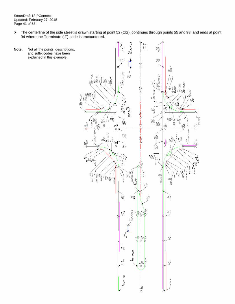
SmartDraft 18 PConnect Updated: February 27, 2018 Page 41 of 53
➢ The centerline of the side street is drawn starting at point 52 (Cl2), continues through points 55 and 93, and ends at point 94 where the Terminate (.T) code is encountered.
Note: Not all the points, descriptions, and suffix codes have been explained in this example.
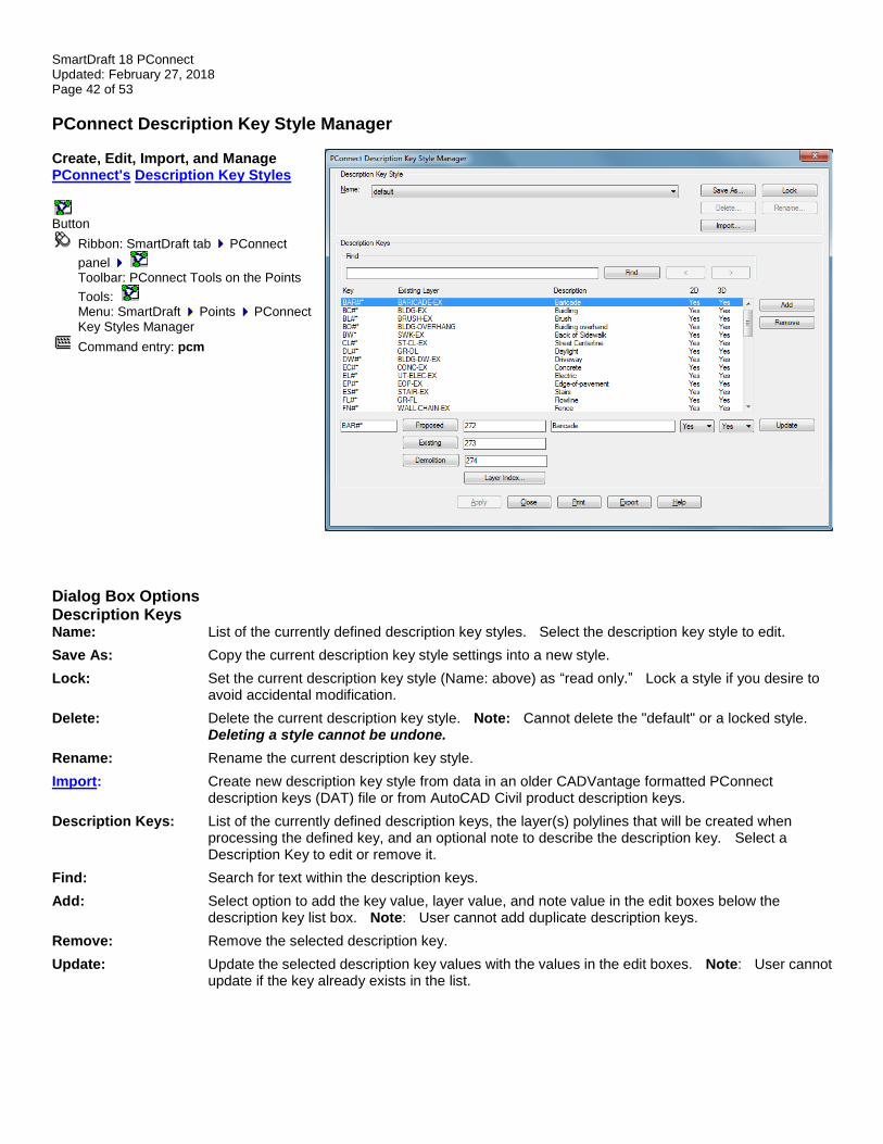
SmartDraft 18 PConnect Updated: February 27, 2018 Page 42 of 53
PConnect Description Key Style Manager Create, Edit, Import, and Manage PConnect's Description Key Styles
Button
Ribbon: SmartDraft tab PConnect
panel Toolbar: PConnect Tools on the Points
Tools: Menu: SmartDraft Points PConnect
Key Styles Manager
Command entry: pcm
Dialog Box Options Description Keys Name: List of the currently defined description key styles. Select the description key style to edit.
Save As: Copy the current description key style settings into a new style.
Lock: Set the current description key style (Name: above) as “read only.” Lock a style if you desire to avoid accidental modification.
Delete: Delete the current description key style. Note: Cannot delete the "default" or a locked style. Deleting a style cannot be undone.
Rename: Rename the current description key style.
Import: Create new description key style from data in an older CADVantage formatted PConnect description keys (DAT) file or from AutoCAD Civil product description keys.
Description Keys: List of the currently defined description keys, the layer(s) polylines that will be created when processing the defined key, and an optional note to describe the description key. Select a Description Key to edit or remove it.
Find: Search for text within the description keys.
Add: Select option to add the key value, layer value, and note value in the edit boxes below the description key list box. Note: User cannot add duplicate description keys.
Remove: Remove the selected description key.
Update: Update the selected description key values with the values in the edit boxes. Note: User cannot update if the key already exists in the list.
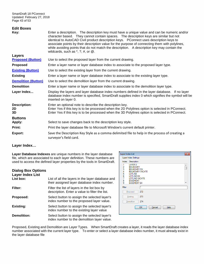
SmartDraft 18 PConnect Updated: February 27, 2018 Page 43 of 53
Edit Boxes Key: Enter a description. The description key must have a unique value and can be numeric and/or
character based. They cannot contain spaces. The description keys are similar but not identical to AutoCAD Civil product description keys. PConnect uses description keys to associate points by their description value for the purpose of connecting them with polylines, while avoiding points that do not match the description. A description key may contain the wildcards, such as *, ?, #, or @.
Layers Proposed (Button) Use to select the proposed layer from the current drawing.
Proposed Enter a layer name or layer database index to associate to the proposed layer type.
Existing (Button) Use to select the existing layer from the current drawing.
Existing Enter a layer name or layer database index to associate to the existing layer type.
Demolition (Button) Use to select the demolition layer from the current drawing.
Demolition Enter a layer name or layer database index to associate to the demolition layer type.
Layer Index... Display the layers and layer database index numbers defined in the layer database. If no layer database index number is specified, SmartDraft supplies index 0 which signifies the symbol will be inserted on layer 0.
Description: Enter an optional note to describe the description key. 2D Enter Yes if this key is to be processed when the 2D Polylines option is selected in PConnect. 3D Enter Yes if this key is to be processed when the 3D Polylines option is selected in PConnect.
Buttons Apply: Select to save changes back to the description key style.
Print: Print the layer database file to Microsoft Window's current default printer.
Export: Save the Description Key Style as a comma delimited file to help in the process of creating a surveyor's field card.
Layer Index…
Layer Database Indexes are unique numbers in the layer database file, which are associated to each layer definition. These numbers are used to access the defined layer properties by the tools in SmartDraft.
Dialog Box Options Layer Index List List box: List of all the layers in the layer database and
their assigned layer database index number.
Filter: Filter the list of layers in the list box by description. Enter a value to filter the list.
Proposed: Select button to assign the selected layer's index number to the proposed layer value.
Existing: Select button to assign the selected layer's index number to the existing layer value
Demolition: Select button to assign the selected layer's index number to the demolition layer value.
Proposed, Existing and Demolition are Layer Types. When SmartDraft creates a layer, it reads the layer database index number associated with the current layer type. To enter or select a layer database index number, it must already exist in the layer database file
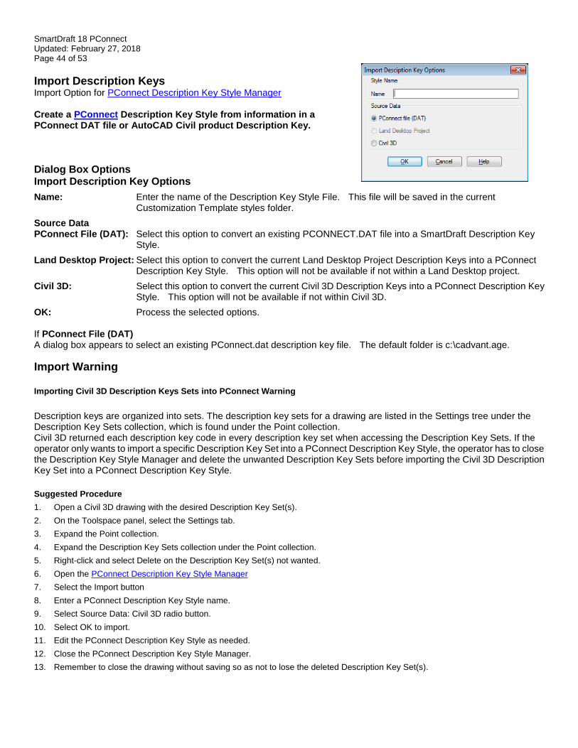
SmartDraft 18 PConnect Updated: February 27, 2018 Page 44 of 53
Import Description Keys Import Option for PConnect Description Key Style Manager Create a PConnect Description Key Style from information in a PConnect DAT file or AutoCAD Civil product Description Key.
Dialog Box Options Import Description Key Options
Name: Enter the name of the Description Key Style File. This file will be saved in the current Customization Template styles folder.
Source Data PConnect File (DAT): Select this option to convert an existing PCONNECT.DAT file into a SmartDraft Description Key
Style.
Land Desktop Project: Select this option to convert the current Land Desktop Project Description Keys into a PConnect Description Key Style. This option will not be available if not within a Land Desktop project.
Civil 3D: Select this option to convert the current Civil 3D Description Keys into a PConnect Description Key Style. This option will not be available if not within Civil 3D.
OK: Process the selected options. If PConnect File (DAT) A dialog box appears to select an existing PConnect.dat description key file. The default folder is c:\cadvant.age.
Import Warning
Importing Civil 3D Description Keys Sets into PConnect Warning
Description keys are organized into sets. The description key sets for a drawing are listed in the Settings tree under the Description Key Sets collection, which is found under the Point collection. Civil 3D returned each description key code in every description key set when accessing the Description Key Sets. If the operator only wants to import a specific Description Key Set into a PConnect Description Key Style, the operator has to close the Description Key Style Manager and delete the unwanted Description Key Sets before importing the Civil 3D Description Key Set into a PConnect Description Key Style.
Suggested Procedure
1. Open a Civil 3D drawing with the desired Description Key Set(s).
2. On the Toolspace panel, select the Settings tab. 3. Expand the Point collection.
4. Expand the Description Key Sets collection under the Point collection. 5. Right-click and select Delete on the Description Key Set(s) not wanted.
6. Open the PConnect Description Key Style Manager 7. Select the Import button
8. Enter a PConnect Description Key Style name. 9. Select Source Data: Civil 3D radio button.
10. Select OK to import. 11. Edit the PConnect Description Key Style as needed.
12. Close the PConnect Description Key Style Manager. 13. Remember to close the drawing without saving so as not to lose the deleted Description Key Set(s).
SmartDraft 18 PConnect Updated: February 27, 2018 Page 45 of 53
Description Key Style File The description key style is used by PConnect to process point descriptions and place the created polylines on the specified layers. Description key styles are:
➢ Stored outside the drawing;
➢ Have the file extension of “.dsy”;
➢ Are stored in the \labels folder of the current Customization Template;
➢ Are a comma delimited file where each line contains a description key, layer information, and note to describe the key;
➢ Are used by PConnect to allow the operator to select which description keys will be used; and
➢ Can be managed by the PConnect Description Key Style Manager. Wildcard characters in description keys:
➢ Each description key must be unique.
Wildcard Description Example
➢ None Matches the specific description
CL Matches CL, but not C, CL1, etc.
➢ # (pound) Matches any single numeric digit
CL# Matches CL1, CL2, ... CL9, but not CL10 because there is a fourth character.
CL#* Matches CL1, CL2, ... CL100 and will also match CL1XYZ, but not EPT1 since the third character is not a numeric digit.
➢ @ (at) Matches any single alphabetic character
CL@ Matches CLE, CLX, etc..., but not CL1, CL2, CL&, or CLXYZ.
CL@#* Matches CL (without anything) or a description starting with CL followed by any single alphabetic (CLT, CLX, CLW, but not CL1 since the third character is a numeric digit), or a description starting with CL followed by any single alphabetic followed by a single numeric digit (EPT1, EPX3, EPW5, EPW01, but not EP1 since the third character is a number).
➢ . (period) Matches any single non-alphanumeric character
➢ * (asterisk) Matches any character sequence, including an empty one, and it can be used anywhere in the search pattern: at the beginning, middle, or end
CL* Matches CL, CL1, CLS, CL100, CL?$#@!, etc.
➢ ? (question mark)
Matches any single character Matches CL1, CL2, CLX, CL>, CL&, etc.
➢ When using numeric description keys, wildcards can cause undesired results if not used carefully. A description key of 1* would match 1, 11, 11111, 12345, 1DA1, etc. But an example of where wildcards could work with numeric description keys would be a case where all top of curb features have a description between 10 and 19. In this case, 1# would match all 10 of these possibilities.
➢ Wildcard characters can be helpful, but if not used correctly, can return some undesired results.
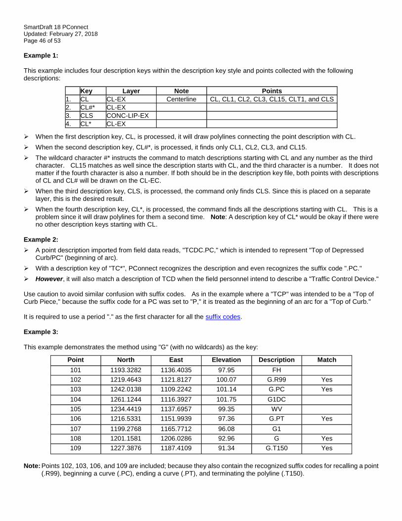
SmartDraft 18 PConnect Updated: February 27, 2018 Page 46 of 53
Example 1: This example includes four description keys within the description key style and points collected with the following descriptions:
Key Layer Note Points
1. CL CL-EX Centerline CL, CL1, CL2, CL3, CL15, CLT1, and CLS
2. CL#* CL-EX
3. CLS CONC-LIP-EX
4. CL* CL-EX
➢ When the first description key, CL, is processed, it will draw polylines connecting the point description with CL.
➢ When the second description key, CL#*, is processed, it finds only CL1, CL2, CL3, and CL15.
➢ The wildcard character #* instructs the command to match descriptions starting with CL and any number as the third character. CL15 matches as well since the description starts with CL, and the third character is a number. It does not matter if the fourth character is also a number. If both should be in the description key file, both points with descriptions of CL and CL# will be drawn on the CL-EC.
➢ When the third description key, CLS, is processed, the command only finds CLS. Since this is placed on a separate layer, this is the desired result.
➢ When the fourth description key, CL*, is processed, the command finds all the descriptions starting with CL. This is a problem since it will draw polylines for them a second time. Note: A description key of CL* would be okay if there were no other description keys starting with CL.
Example 2:
➢ A point description imported from field data reads, "TCDC.PC," which is intended to represent "Top of Depressed Curb/PC" (beginning of arc).
➢ With a description key of "TC*", PConnect recognizes the description and even recognizes the suffix code ".PC."
➢ However, it will also match a description of TCD when the field personnel intend to describe a "Traffic Control Device." Use caution to avoid similar confusion with suffix codes. As in the example where a "TCP" was intended to be a "Top of Curb Piece," because the suffix code for a PC was set to "P," it is treated as the beginning of an arc for a "Top of Curb." It is required to use a period "." as the first character for all the suffix codes. Example 3: This example demonstrates the method using "G" (with no wildcards) as the key:
Point North East Elevation Description Match
101 1193.3282 1136.4035 97.95 FH
102 1219.4643 1121.8127 100.07 G.R99 Yes
103 1242.0138 1109.2242 101.14 G.PC Yes
104 1261.1244 1116.3927 101.75 G1DC
105 1234.4419 1137.6957 99.35 WV
106 1216.5331 1151.9939 97.36 G.PT Yes
107 1199.2768 1165.7712 96.08 G1
108 1201.1581 1206.0286 92.96 G Yes
109 1227.3876 1187.4109 91.34 G.T150 Yes
Note: Points 102, 103, 106, and 109 are included; because they also contain the recognized suffix codes for recalling a point
(.R99), beginning a curve (.PC), ending a curve (.PT), and terminating the polyline (.T150).
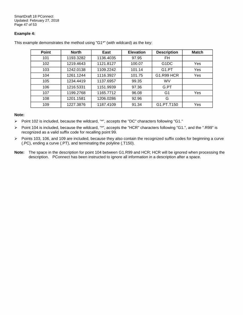
SmartDraft 18 PConnect Updated: February 27, 2018 Page 47 of 53
Example 4: This example demonstrates the method using "G1*" (with wildcard) as the key:
Point North East Elevation Description Match
101 1193.3282 1136.4035 97.95 FH
102 1219.4643 1121.8127 100.07 G1DC Yes
103 1242.0138 1109.2242 101.14 G1.PT Yes
104 1261.1244 1116.3927 101.75 G1.R99 HCR Yes
105 1234.4419 1137.6957 99.35 WV
106 1216.5331 1151.9939 97.36 G.PT
107 1199.2768 1165.7712 96.08 G1 Yes
108 1201.1581 1206.0286 92.96 G
109 1227.3876 1187.4109 91.34 G1.PT.T150 Yes
Note:
➢ Point 102 is included, because the wildcard, "*", accepts the "DC" characters following "G1."
➢ Point 104 is included, because the wildcard, "*", accepts the "HCR" characters following "G1.", and the ".R99" is recognized as a valid suffix code for recalling point 99.
➢ Points 103, 106, and 109 are included, because they also contain the recognized suffix codes for beginning a curve (.PC), ending a curve (.PT), and terminating the polyline (.T150).
Note: The space in the description for point 104 between G1.R99 and HCR; HCR will be ignored when processing the description. PConnect has been instructed to ignore all information in a description after a space.
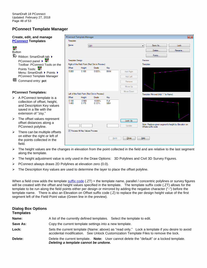
SmartDraft 18 PConnect Updated: February 27, 2018 Page 48 of 53
PConnect Template Manager Create, edit, and manage PConnect Templates
Button
Ribbon: SmartDraft tab
PConnect panel Toolbar: PConnect Tools on the
Points Tools: Menu: SmartDraft Points
PConnect Template Manager
Command entry: pct
PConnect Templates:
➢ A PConnect template is a collection of offset, height, and Description Key values saved in a file with the extension of “zsy.”
➢ The offset values represent offset distances along a PConnect polyline.
➢ There can be multiple offsets on either the right or left of the points collected in the field.
➢ The height values are the changes in elevation from the point collected in the field and are relative to the last segment along the template.
➢ The height adjustment value is only used in the Draw Options: 3D Polylines and Civil 3D Survey Figures.
➢ PConnect always draws 2D Polylines at elevation zero (0.0).
➢ The Description Key values are used to determine the layer to place the offset polyline. When a field crew adds the template suffix code (.ZT) + the template name, parallel / concentric polylines or survey figures will be created with the offset and height values specified in the template. The template suffix code (.ZT) allows for the template to be run along the field points either per design or mirrored by adding the negative character ("-") before the template name. There is also an Elevation on Offset suffix code (.Z) to replace the per design height value of the first segment left of the Field Point value (Green line in the preview).
Dialog Box Options Templates
Name: A list of the currently defined templates. Select the template to edit.
Save As: Copy the current template settings into a new template.
Lock: Sets the current template (Name: above) as “read only.” Lock a template if you desire to avoid accidental modification. See Unlock Customization Template Files to remove the lock.
Delete: Delete the current template. Note: User cannot delete the "default" or a locked template. Deleting a template cannot be undone.
SmartDraft 18 PConnect Updated: February 27, 2018 Page 49 of 53
Rename: Rename the current template.
Points: Create a template from selecting point objects in the drawing.
Template Design Right of the Field List of the Offsets, Heights, Grades, and Description Keys for offset polylines to be drawn to Point: the right of the collected field point.
Left of the Field List of the Offsets, Heights, Grades, and Description Keys for offset polylines to be drawn to the Point: left of the collected field point.
Note: The selected values will display as a thicker line in the Preview boxes.
Buttons Add Right: Select option to add the offset value, height value, and description key value in the edit boxes below
the Right of the Field Point list box.
Add Left: Select option to add the offset value, height value, and description key value in the edit boxes below the Left of the Field Point list box.
Remove: Remove the selected values from either the Right or Left of the Field Point list boxes.
Move Up: Change location in list up.
Move Down: Change location in list down.
Lock Up: Open the Description Key Look Up dialog box to search for a Description Key from any of the Description Key Styles.
Update: Update the selected offset, height, and Description Key values with the values in the edit boxes.
Edit Boxes Offset: Enter an offset value. The value will be relative to the previous point. Only positive and non-zero
values are valid.
Height: Enter a height value. The value will be relative to the previous point. Positive, negative, and zero values are all valid.
Key: Enter a description key. This value is used to match a value in the Description Key style file used during processing of the points. If a match is found, the command will draw the new polyline or survey figure on the layer specified in the Description Key style.
Process All Key A template can have a different Key for each point. The Key is used for two purposes. First, Values: if the Key is found in the Description Key Style files with an associated layer, the polyline is drawn
on that layer. Second, the Key can be a filter to exclude the Key from being processed, unless it is selected from the Description Key List when running PConnect. If this option is checked in the template, all Keys within the template will be processed as long as the main description key associated with the template name was selected.
Preview Template per Design: A preview of the offset and height values in the Right and Left of the Field Point list boxes. These
are the values used if the template suffix code + template are used.
Template Mirrored: A preview of the mirrored offset and height values in the Right and Left of the Field Point list boxes. These are the values used if the template suffix code + "-" (negative character) + template name are used.
Note: The green line in the preview is the first offset and height values are in the Left of the Field Point list box. The height value of this segment can be replaced in the field by using the Elevation on Offsets suffix code (.Z) + new height and returned to the template height value by using the Elevation on Offsets suffix code (.Z) without a height value.
Buttons Apply: Select to save changes back to the template file. Template Examples

SmartDraft 18 PConnect Updated: February 27, 2018 Page 50 of 53
Description Key Look Up Look Up Option for PConnect Template Manager Look Up a Description Key from the currently saved Description Key Styles created for PConnect.
Dialog Box Options Description Key Look Up Name: Select the name of the Description Key Style file to list. This file will be saved in the current
Customization Template styles folder.
Description Keys List: Select a description key from the list to place in the edit box.
Edit Box: The currently selected or entered Description Key.
Buttons OK: Places the Description Key text from the Edit Box into the Key box of the PConnect Template
Manager dialog.
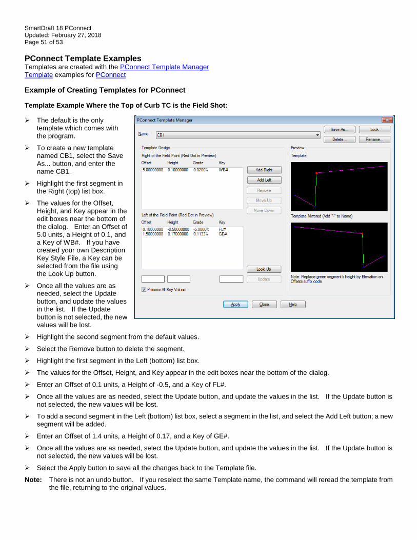
SmartDraft 18 PConnect Updated: February 27, 2018 Page 51 of 53
PConnect Template Examples Templates are created with the PConnect Template Manager Template examples for PConnect
Example of Creating Templates for PConnect
Template Example Where the Top of Curb TC is the Field Shot:
➢ The default is the only template which comes with the program.
➢ To create a new template named CB1, select the Save As... button, and enter the name CB1.
➢ Highlight the first segment in the Right (top) list box.
➢ The values for the Offset, Height, and Key appear in the edit boxes near the bottom of the dialog. Enter an Offset of 5.0 units, a Height of 0.1, and a Key of WB#. If you have created your own Description Key Style File, a Key can be selected from the file using the Look Up button.
➢ Once all the values are as needed, select the Update button, and update the values in the list. If the Update button is not selected, the new values will be lost.
➢ Highlight the second segment from the default values.
➢ Select the Remove button to delete the segment.
➢ Highlight the first segment in the Left (bottom) list box.
➢ The values for the Offset, Height, and Key appear in the edit boxes near the bottom of the dialog.
➢ Enter an Offset of 0.1 units, a Height of -0.5, and a Key of FL#.
➢ Once all the values are as needed, select the Update button, and update the values in the list. If the Update button is not selected, the new values will be lost.
➢ To add a second segment in the Left (bottom) list box, select a segment in the list, and select the Add Left button; a new segment will be added.
➢ Enter an Offset of 1.4 units, a Height of 0.17, and a Key of GE#.
➢ Once all the values are as needed, select the Update button, and update the values in the list. If the Update button is not selected, the new values will be lost.
➢ Select the Apply button to save all the changes back to the Template file.
Note: There is not an undo button. If you reselect the same Template name, the command will reread the template from the file, returning to the original values.
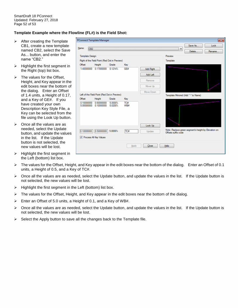
SmartDraft 18 PConnect Updated: February 27, 2018 Page 52 of 53
Template Example where the Flowline (FL#) is the Field Shot:
➢ After creating the Template CB1, create a new template named CB2, select the Save As... button, and enter the name “CB2.”
➢ Highlight the first segment in the Right (top) list box.
➢ The values for the Offset, Height, and Key appear in the edit boxes near the bottom of the dialog. Enter an Offset of 1.4 units, a Height of 0.17, and a Key of GE#. If you have created your own Description Key Style File, a Key can be selected from the file using the Look Up button.
➢ Once all the values are as needed, select the Update button, and update the values in the list. If the Update button is not selected, the new values will be lost.
➢ Highlight the first segment in the Left (bottom) list box.
➢ The values for the Offset, Height, and Key appear in the edit boxes near the bottom of the dialog. Enter an Offset of 0.1 units, a Height of 0.5, and a Key of TC#.
➢ Once all the values are as needed, select the Update button, and update the values in the list. If the Update button is not selected, the new values will be lost.
➢ Highlight the first segment in the Left (bottom) list box.
➢ The values for the Offset, Height, and Key appear in the edit boxes near the bottom of the dialog.
➢ Enter an Offset of 5.0 units, a Height of 0.1, and a Key of WB#.
➢ Once all the values are as needed, select the Update button, and update the values in the list. If the Update button is not selected, the new values will be lost.
➢ Select the Apply button to save all the changes back to the Template file.
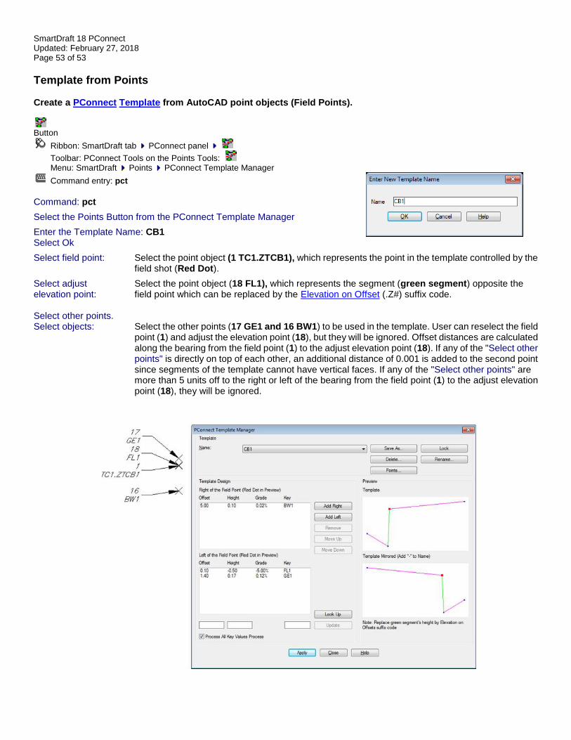
SmartDraft 18 PConnect Updated: February 27, 2018 Page 53 of 53
Template from Points Create a PConnect Template from AutoCAD point objects (Field Points).
Button
Ribbon: SmartDraft tab PConnect panel
Toolbar: PConnect Tools on the Points Tools: Menu: SmartDraft Points PConnect Template Manager
Command entry: pct
Command: pct
Select the Points Button from the PConnect Template Manager
Enter the Template Name: CB1 Select Ok
Select field point: Select the point object (1 TC1.ZTCB1), which represents the point in the template controlled by the field shot (Red Dot).
Select adjust Select the point object (18 FL1), which represents the segment (green segment) opposite the elevation point: field point which can be replaced by the Elevation on Offset (.Z#) suffix code. Select other points. Select objects: Select the other points (17 GE1 and 16 BW1) to be used in the template. User can reselect the field
point (1) and adjust the elevation point (18), but they will be ignored. Offset distances are calculated along the bearing from the field point (1) to the adjust elevation point (18). If any of the "Select other points" is directly on top of each other, an additional distance of 0.001 is added to the second point since segments of the template cannot have vertical faces. If any of the "Select other points" are more than 5 units off to the right or left of the bearing from the field point (1) to the adjust elevation point (18), they will be ignored.