smartview plus user manual - ctc u manual smartview plus ... quick installation guide, ... smartview...
TRANSCRIPT
USER MANUAL
SmartView Plus SVP DVS Management System.
CTC Union Technologies Co., Ltd.

LEGAL The information in this publication has been carefully checked and is believed to be entirely accurate at the time of publication. CTC Union Technologies assumes no responsibility, however, for possible errors or omissions, or for any consequences resulting from the use of the information contained herein. CTC Union Technologies reserves the right to make changes in its products or product specifications with the intent to improve function or design at any time and without notice and is not required to update this documentation to reflect such changes. CTC Union Technologies makes no warranty, representation, or guarantee regarding the suitability of its products for any particular purpose, nor does CTC Union assume any liability arising out of the application or use of any product and specifically disclaims any and all liability, including without limitation any consequential or incidental damages. CTC Union products are not designed, intended, or authorized for use in systems or applications intended to support or sustain life, or for any other application in which the failure of the product could create a situation where personal injury or death may occur. Should the Buyer purchase or use a CTC Union product for any such unintended or unauthorized application, the Buyer shall indemnify and hold CTC Union Technologies and its officers, employees, subsidiaries, affiliates, and distributors harmless against all claims, costs, damages, expenses, and reasonable attorney fees arising out of, either directly or indirectly, any claim of personal injury or death that may be associated with such unintended or unauthorized use, even if such claim alleges that CTC Union Technologies was negligent regarding the design or manufacture of said product. TRADEMARKS Microsoft is a registered trademark of Microsoft Corp. HyperTerminal™ is a registered trademark of Hilgraeve Inc. User Manual Version 1.0 Oct 2007 First Release This manual supports the following: SmartView Plus SVP Cascade Management System An Intelligent and Comprehensive Surveillance System Software Version 2.4.1 This document is the first official release manual. Please check CTC Union's website for any updated manual or contact us by E-mail at [email protected]. Please address any comments for improving this manual or to point out omissions or errors to [email protected]. Thank you. CTC Union maintains a support web site (support.ctcu.com) where you may obtain the latest manual, quick installation guide, and operational firmware. Membership to this web site is free, however, you must be a registered member in order to access any software updates. CTC Union Technologies Co., Ltd. 2007 Copyright, All rights reserved.

Table of Contents
CHAPTER 1 INTRODUCTION.................................................................................................................................................7
1.1 MAIN FUNCTIONS.................................................................................................................................................................7 CHAPTER 2 THE CONTROL PROGRAM ..........................................................................................................................8
2.1 AUTOMATICALLY STARTS UPON SYSTEM BOOT UP .................................................................................................................8 2.2 SHUTTING DOWN THE CONTROL PROGRAM..........................................................................................................................8 2.3 START THE CONTROL PROGRAM MANUALLY.........................................................................................................................8
CHAPTER 3 THE ADMIN PROGRAM ................................................................................................................................9 3.1 SYSTEM LOGIN .....................................................................................................................................................................9 3.2 THE ADMIN PROGRAM INTERFACE .......................................................................................................................................9 3.3 SYSTEM MANAGEMENT......................................................................................................................................................10 3.4 USER GROUP AND USER .....................................................................................................................................................22 3.5 SITE E-MAP .........................................................................................................................................................................27 3.6 SITE OPERATIONS ...............................................................................................................................................................34 3.7 AREA OPERATIONS .............................................................................................................................................................36 3.8 DEVICES AND DEVICE CONFIGURATION..............................................................................................................................40 3.9 EXITING THE ADMIN PROGRAM ..........................................................................................................................................57
CHAPTER 4 THE MONITOR PROGRAM ........................................................................................................................58 4.1 SYSTEM LOGIN ...................................................................................................................................................................58 4.2 THE MONITOR PROGRAM INTERFACE .................................................................................................................................58 4.3 VIDEO DISPLAY AREA.........................................................................................................................................................58 4.4 DISPLAY SELECT TOOLBAR .................................................................................................................................................59 4.5 ALARM LISTING..................................................................................................................................................................60 4.6 IMAGE CONTROL AND SYSTEM FUNCTIONS ........................................................................................................................60 4.7 PTZ CONTROL INTERFACE..................................................................................................................................................69 4.8 ALARM E-MAP....................................................................................................................................................................69 4.9 EXITING THE MONITOR PROGRAM......................................................................................................................................69
CHAPTER 5 THE SVP VIEWER PROGRAM (MULTLI-CHANNELS PLAYBACK)..................................................70 5.1 RUNNING SVP VIEWER ......................................................................................................................................................70 5.2 MAIN DISPLAY AREA..........................................................................................................................................................70 5.3 FUNCTION AREA.................................................................................................................................................................71 5.4 VIDEO DISPLAY AND QUERY RESULT AREA ........................................................................................................................71 5.5 QUERY CRITERIA AREA ......................................................................................................................................................71 5.6 RECORDING HISTORY QUERY .............................................................................................................................................71 5.7 RECORDING HISTORY PLAYBACK .......................................................................................................................................74 5.8 EXITING THE SVP VIEWER PROGRAM ................................................................................................................................76

Table of Contents
Chapter 1 Introduction
- 7 -
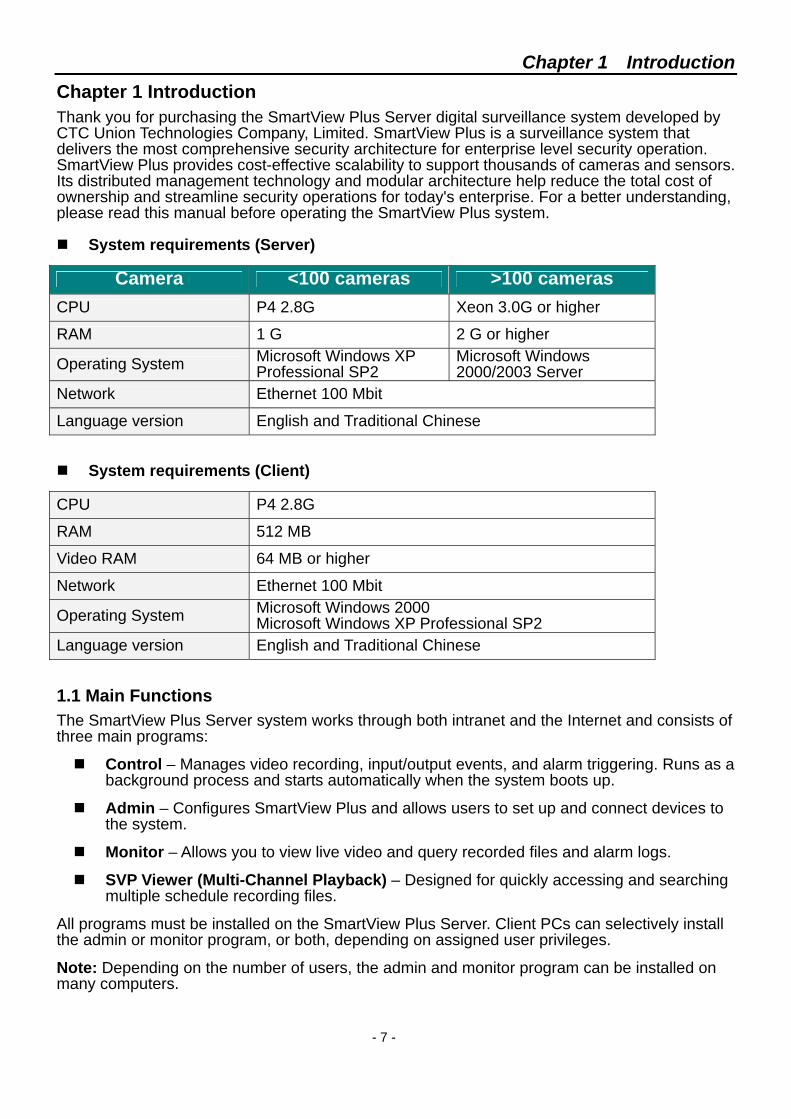
Chapter 1 Introduction Thank you for purchasing the SmartView Plus Server digital surveillance system developed by CTC Union Technologies Company, Limited. SmartView Plus is a surveillance system that delivers the most comprehensive security architecture for enterprise level security operation. SmartView Plus provides cost-effective scalability to support thousands of cameras and sensors. Its distributed management technology and modular architecture help reduce the total cost of ownership and streamline security operations for today's enterprise. For a better understanding, please read this manual before operating the SmartView Plus system.
System requirements (Server)
Camera <100 cameras >100 cameras CPU P4 2.8G Xeon 3.0G or higher
RAM 1 G 2 G or higher
Operating System Microsoft Windows XP Professional SP2
Microsoft Windows 2000/2003 Server
Network Ethernet 100 Mbit
Language version English and Traditional Chinese
System requirements (Client)
CPU P4 2.8G
RAM 512 MB
Video RAM 64 MB or higher
Network Ethernet 100 Mbit
Operating System Microsoft Windows 2000 Microsoft Windows XP Professional SP2
Language version English and Traditional Chinese
1.1 Main Functions The SmartView Plus Server system works through both intranet and the Internet and consists of three main programs:
Control – Manages video recording, input/output events, and alarm triggering. Runs as a background process and starts automatically when the system boots up.
Admin – Configures SmartView Plus and allows users to set up and connect devices to the system.
Monitor – Allows you to view live video and query recorded files and alarm logs.
SVP Viewer (Multi-Channel Playback) – Designed for quickly accessing and searching multiple schedule recording files.
All programs must be installed on the SmartView Plus Server. Client PCs can selectively install the admin or monitor program, or both, depending on assigned user privileges.
Note: Depending on the number of users, the admin and monitor program can be installed on many computers.
Chapter 2 The Control Program
- 8 -
Chapter 2 The Control Program 2.1 Automatically starts upon system boot up
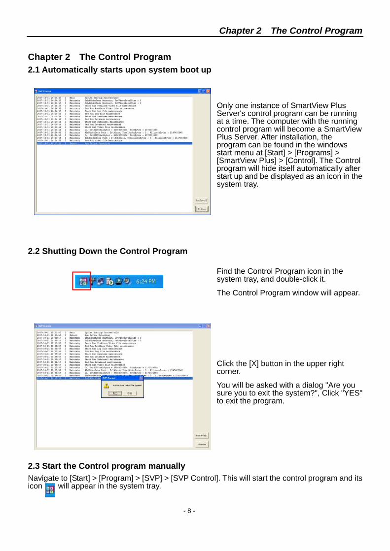
Only one instance of SmartView Plus Server's control program can be running at a time. The computer with the running control program will become a SmartView Plus Server. After installation, the program can be found in the windows start menu at [Start] > [Programs] > [SmartView Plus] > [Control]. The Control program will hide itself automatically after start up and be displayed as an icon in the system tray.
2.2 Shutting Down the Control Program
Find the Control Program icon in the system tray, and double-click it.
The Control Program window will appear.
Click the [X] button in the upper right corner.
You will be asked with a dialog "Are you sure you to exit the system?", Click "YES" to exit the program.
2.3 Start the Control program manually Navigate to [Start] > [Program] > [SVP] > [SVP Control]. This will start the control program and its icon will appear in the system tray.
Chapter 3 The Admin Program
- 9 -
Chapter 3 The Admin Program Multiple instances of the SmartView Plus Server Admin program can be run on a PC at the same time.
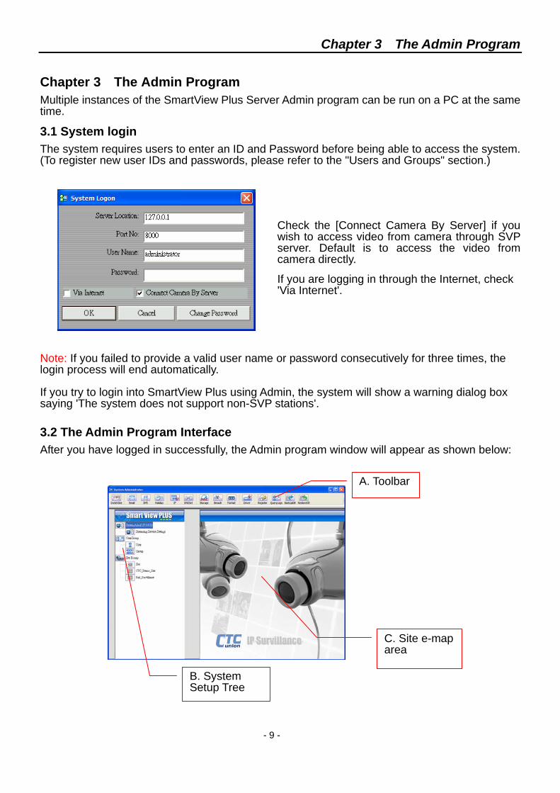
3.1 System login The system requires users to enter an ID and Password before being able to access the system. (To register new user IDs and passwords, please refer to the "Users and Groups" section.)
Check the [Connect Camera By Server] if you wish to access video from camera through SVP server. Default is to access the video from camera directly.
If you are logging in through the Internet, check 'Via Internet'.
Note: If you failed to provide a valid user name or password consecutively for three times, the login process will end automatically. If you try to login into SmartView Plus using Admin, the system will show a warning dialog box saying 'The system does not support non-SVP stations'. 3.2 The Admin Program Interface After you have logged in successfully, the Admin program window will appear as shown below:
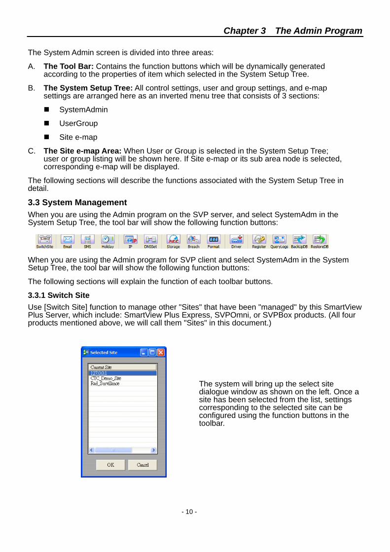
B. System Setup Tree
C. Site e-map area
A. Toolbar
Chapter 3 The Admin Program
- 10 -
The System Admin screen is divided into three areas:
A. The Tool Bar: Contains the function buttons which will be dynamically generated according to the properties of item which selected in the System Setup Tree.
B. The System Setup Tree: All control settings, user and group settings, and e-map settings are arranged here as an inverted menu tree that consists of 3 sections:
SystemAdmin
UserGroup
Site e-map
C. The Site e-map Area: When User or Group is selected in the System Setup Tree; user or group listing will be shown here. If Site e-map or its sub area node is selected, corresponding e-map will be displayed.
The following sections will describe the functions associated with the System Setup Tree in detail.
3.3 System Management When you are using the Admin program on the SVP server, and select SystemAdm in the System Setup Tree, the tool bar will show the following function buttons:
When you are using the Admin program for SVP client and select SystemAdm in the System Setup Tree, the tool bar will show the following function buttons:
The following sections will explain the function of each toolbar buttons.
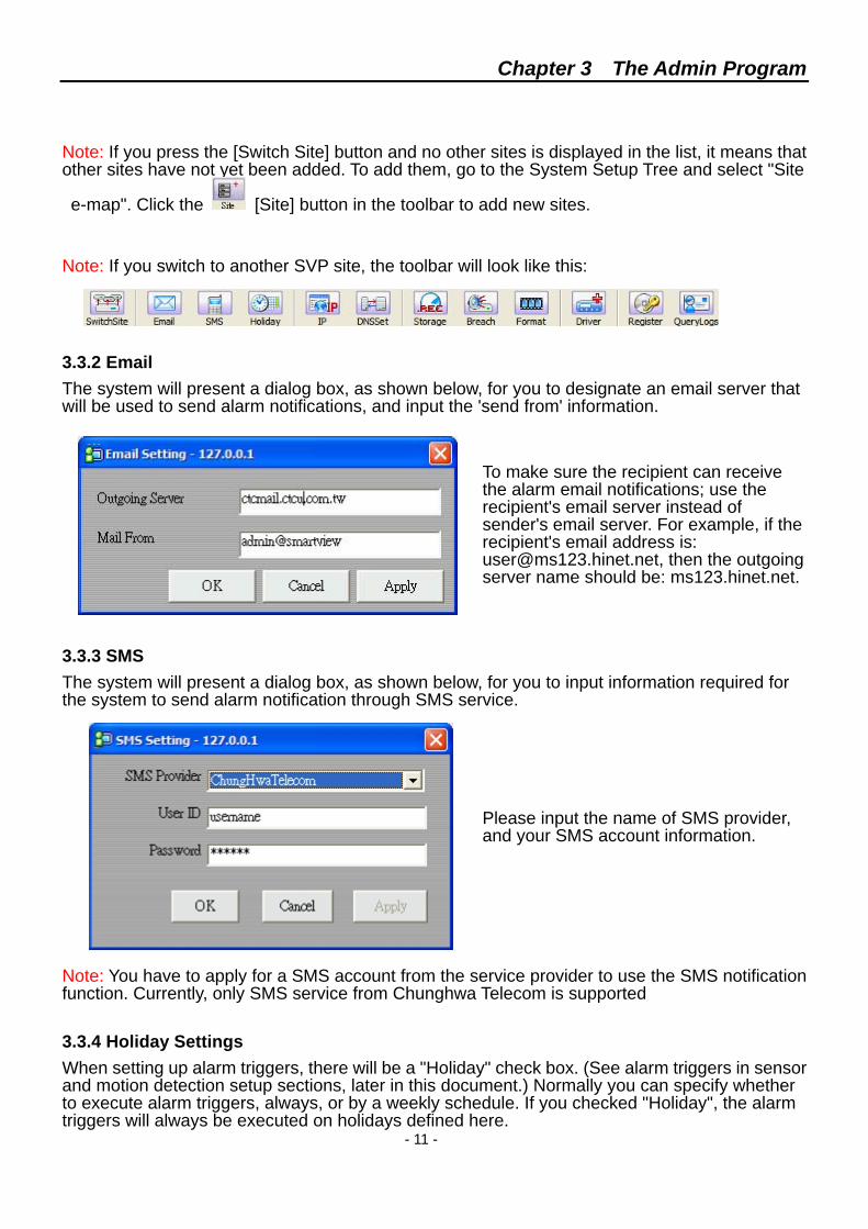
3.3.1 Switch Site Use [Switch Site] function to manage other "Sites" that have been "managed" by this SmartView Plus Server, which include: SmartView Plus Express, SVPOmni, or SVPBox products. (All four products mentioned above, we will call them "Sites" in this document.)
The system will bring up the select site dialogue window as shown on the left. Once a site has been selected from the list, settings corresponding to the selected site can be configured using the function buttons in the toolbar.
Chapter 3 The Admin Program
- 11 -
Note: If you press the [Switch Site] button and no other sites is displayed in the list, it means that other sites have not yet been added. To add them, go to the System Setup Tree and select "Site e-map". Click the [Site] button in the toolbar to add new sites.
Note: If you switch to another SVP site, the toolbar will look like this:
3.3.2 Email The system will present a dialog box, as shown below, for you to designate an email server that will be used to send alarm notifications, and input the 'send from' information.
To make sure the recipient can receive the alarm email notifications; use the recipient's email server instead of sender's email server. For example, if the recipient's email address is: [email protected], then the outgoing server name should be: ms123.hinet.net.
3.3.3 SMS The system will present a dialog box, as shown below, for you to input information required for the system to send alarm notification through SMS service.
Please input the name of SMS provider, and your SMS account information.
Note: You have to apply for a SMS account from the service provider to use the SMS notification function. Currently, only SMS service from Chunghwa Telecom is supported
3.3.4 Holiday Settings When setting up alarm triggers, there will be a "Holiday" check box. (See alarm triggers in sensor and motion detection setup sections, later in this document.) Normally you can specify whether to execute alarm triggers, always, or by a weekly schedule. If you checked "Holiday", the alarm triggers will always be executed on holidays defined here.
Chapter 3 The Admin Program
- 12 -
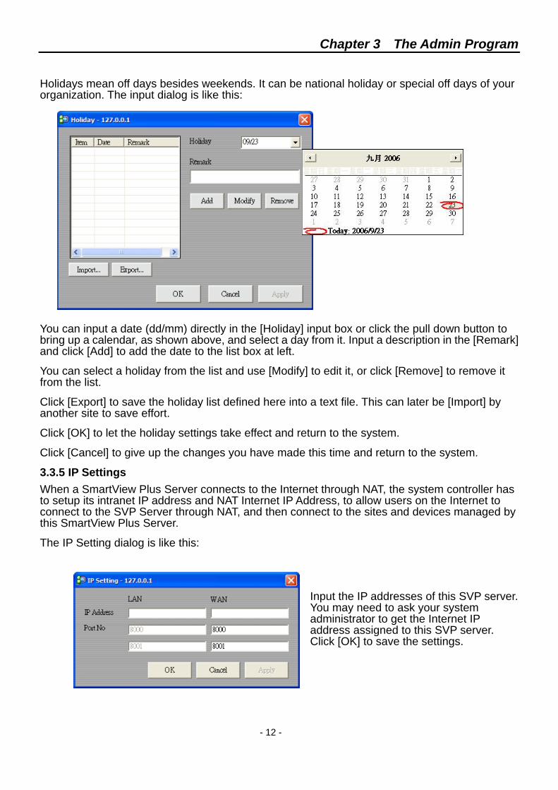
Holidays mean off days besides weekends. It can be national holiday or special off days of your organization. The input dialog is like this:
You can input a date (dd/mm) directly in the [Holiday] input box or click the pull down button to bring up a calendar, as shown above, and select a day from it. Input a description in the [Remark] and click [Add] to add the date to the list box at left.
You can select a holiday from the list and use [Modify] to edit it, or click [Remove] to remove it from the list.
Click [Export] to save the holiday list defined here into a text file. This can later be [Import] by another site to save effort.
Click [OK] to let the holiday settings take effect and return to the system.
Click [Cancel] to give up the changes you have made this time and return to the system.
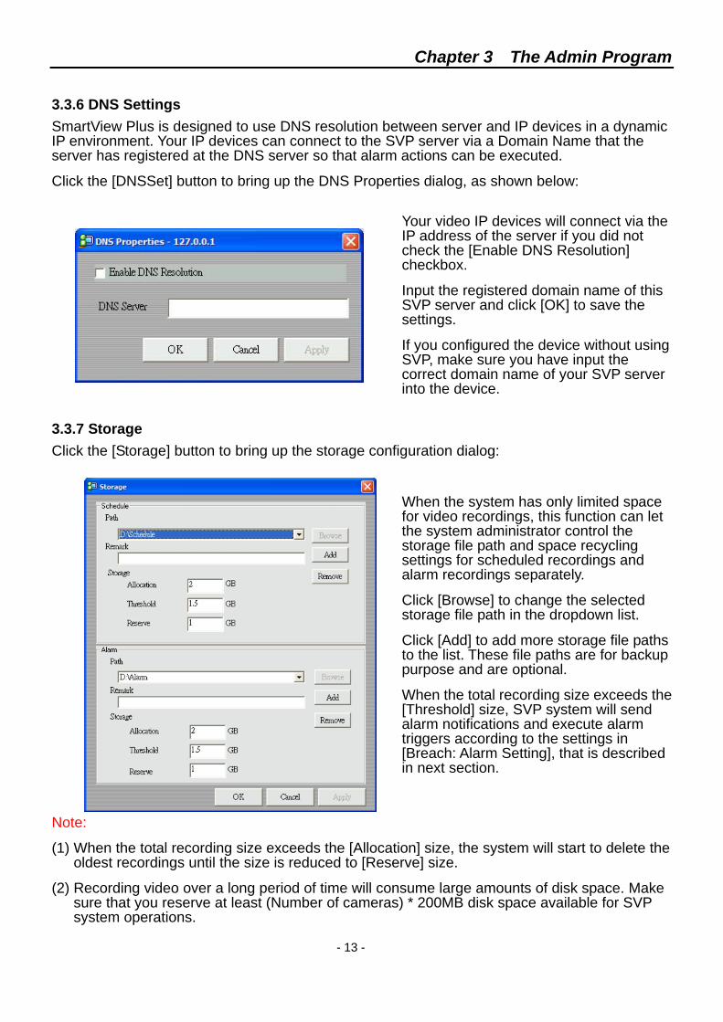
3.3.5 IP Settings When a SmartView Plus Server connects to the Internet through NAT, the system controller has to setup its intranet IP address and NAT Internet IP Address, to allow users on the Internet to connect to the SVP Server through NAT, and then connect to the sites and devices managed by this SmartView Plus Server.
The IP Setting dialog is like this:
Input the IP addresses of this SVP server. You may need to ask your system administrator to get the Internet IP address assigned to this SVP server. Click [OK] to save the settings.
Chapter 3 The Admin Program
- 13 -
3.3.6 DNS Settings SmartView Plus is designed to use DNS resolution between server and IP devices in a dynamic IP environment. Your IP devices can connect to the SVP server via a Domain Name that the server has registered at the DNS server so that alarm actions can be executed.
Click the [DNSSet] button to bring up the DNS Properties dialog, as shown below:
Your video IP devices will connect via the IP address of the server if you did not check the [Enable DNS Resolution] checkbox.
Input the registered domain name of this SVP server and click [OK] to save the settings.
If you configured the device without using SVP, make sure you have input the correct domain name of your SVP server into the device.
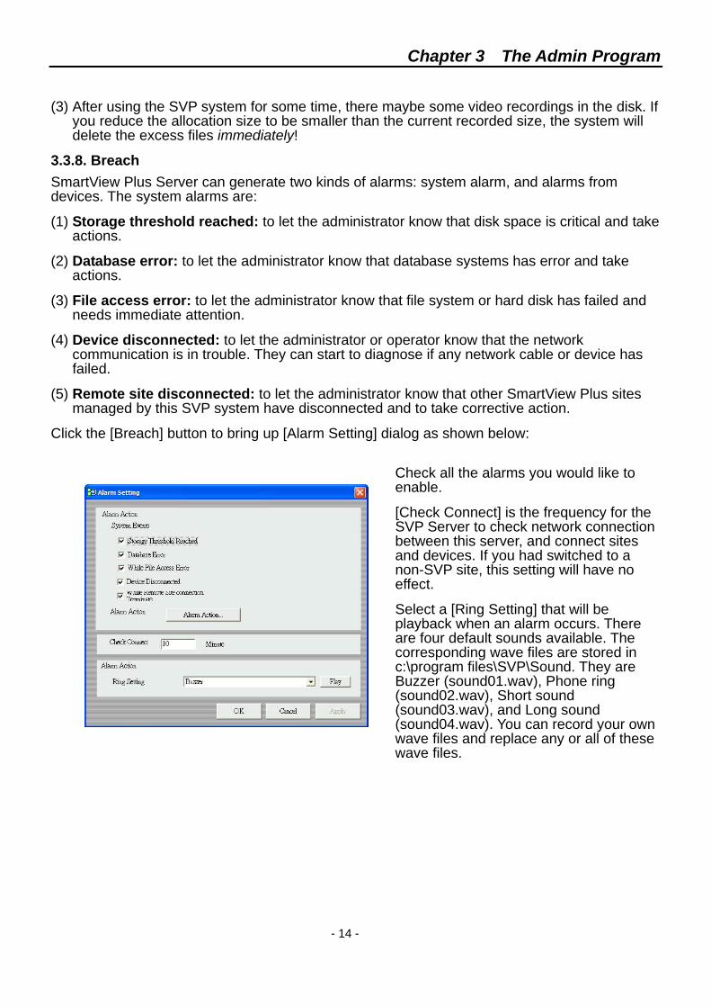
3.3.7 Storage Click the [Storage] button to bring up the storage configuration dialog:
When the system has only limited space for video recordings, this function can let the system administrator control the storage file path and space recycling settings for scheduled recordings and alarm recordings separately.
Click [Browse] to change the selected storage file path in the dropdown list.
Click [Add] to add more storage file paths to the list. These file paths are for backup purpose and are optional.
When the total recording size exceeds the [Threshold] size, SVP system will send alarm notifications and execute alarm triggers according to the settings in [Breach: Alarm Setting], that is described in next section.
Note:
(1) When the total recording size exceeds the [Allocation] size, the system will start to delete the oldest recordings until the size is reduced to [Reserve] size.
(2) Recording video over a long period of time will consume large amounts of disk space. Make sure that you reserve at least (Number of cameras) * 200MB disk space available for SVP system operations.
Chapter 3 The Admin Program
- 14 -
(3) After using the SVP system for some time, there maybe some video recordings in the disk. If you reduce the allocation size to be smaller than the current recorded size, the system will delete the excess files immediately!
3.3.8. Breach SmartView Plus Server can generate two kinds of alarms: system alarm, and alarms from devices. The system alarms are:
(1) Storage threshold reached: to let the administrator know that disk space is critical and take actions.
(2) Database error: to let the administrator know that database systems has error and take actions.
(3) File access error: to let the administrator know that file system or hard disk has failed and needs immediate attention.
(4) Device disconnected: to let the administrator or operator know that the network communication is in trouble. They can start to diagnose if any network cable or device has failed.
(5) Remote site disconnected: to let the administrator know that other SmartView Plus sites managed by this SVP system have disconnected and to take corrective action.
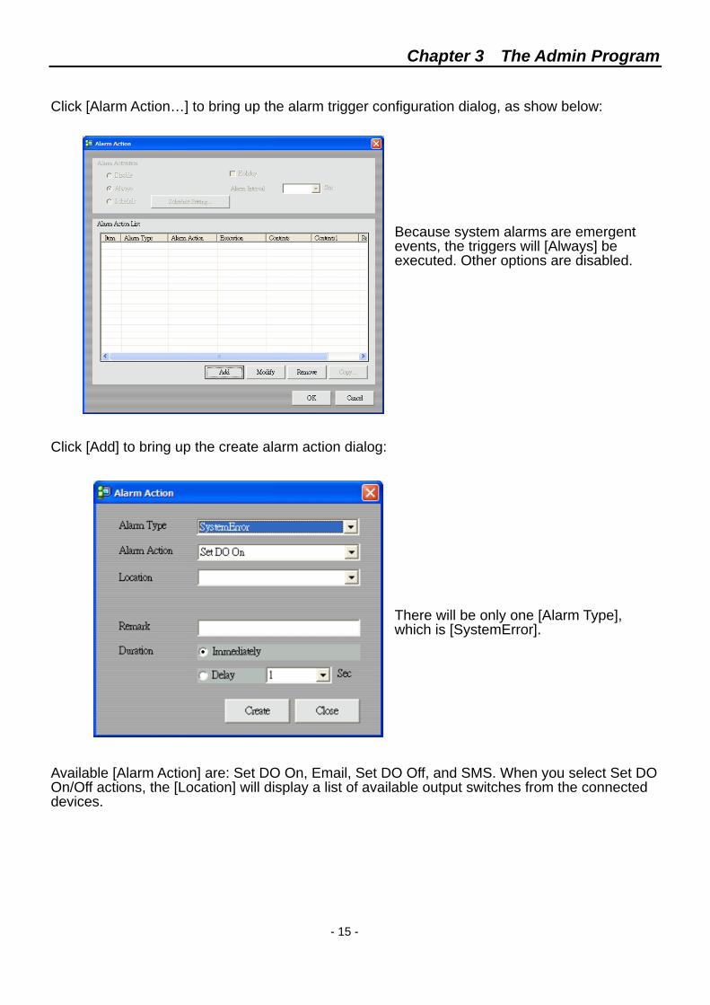
Click the [Breach] button to bring up [Alarm Setting] dialog as shown below:
Check all the alarms you would like to enable.
[Check Connect] is the frequency for the SVP Server to check network connection between this server, and connect sites and devices. If you had switched to a non-SVP site, this setting will have no effect.
Select a [Ring Setting] that will be playback when an alarm occurs. There are four default sounds available. The corresponding wave files are stored in c:\program files\SVP\Sound. They are Buzzer (sound01.wav), Phone ring (sound02.wav), Short sound (sound03.wav), and Long sound (sound04.wav). You can record your own wave files and replace any or all of these wave files.
Chapter 3 The Admin Program
- 15 -
Click [Alarm Action…] to bring up the alarm trigger configuration dialog, as show below:
Because system alarms are emergent events, the triggers will [Always] be executed. Other options are disabled.
Click [Add] to bring up the create alarm action dialog:
There will be only one [Alarm Type], which is [SystemError].
Available [Alarm Action] are: Set DO On, Email, Set DO Off, and SMS. When you select Set DO On/Off actions, the [Location] will display a list of available output switches from the connected devices.
Chapter 3 The Admin Program
- 16 -
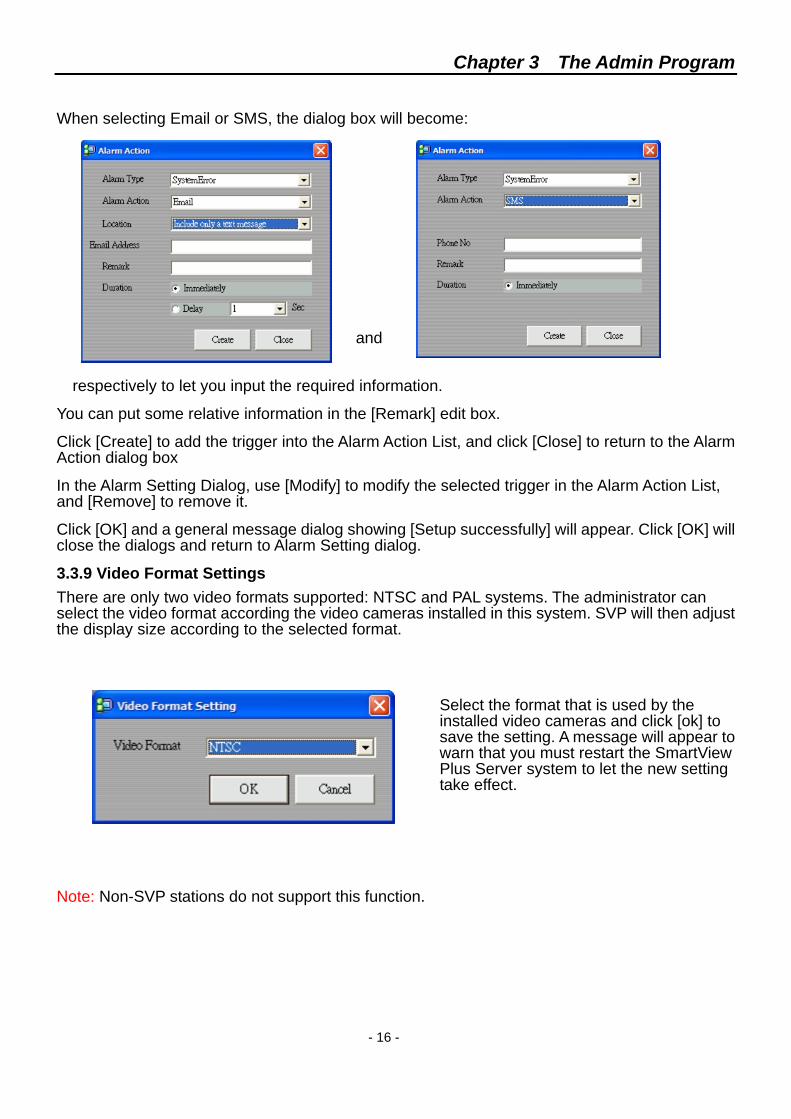
When selecting Email or SMS, the dialog box will become:
and respectively to let you input the required information.
You can put some relative information in the [Remark] edit box.
Click [Create] to add the trigger into the Alarm Action List, and click [Close] to return to the Alarm Action dialog box
In the Alarm Setting Dialog, use [Modify] to modify the selected trigger in the Alarm Action List, and [Remove] to remove it.
Click [OK] and a general message dialog showing [Setup successfully] will appear. Click [OK] will close the dialogs and return to Alarm Setting dialog.
3.3.9 Video Format Settings There are only two video formats supported: NTSC and PAL systems. The administrator can select the video format according the video cameras installed in this system. SVP will then adjust the display size according to the selected format.
Select the format that is used by the installed video cameras and click [ok] to save the setting. A message will appear to warn that you must restart the SmartView Plus Server system to let the new setting take effect.
Note: Non-SVP stations do not support this function.
Chapter 3 The Admin Program
- 17 -
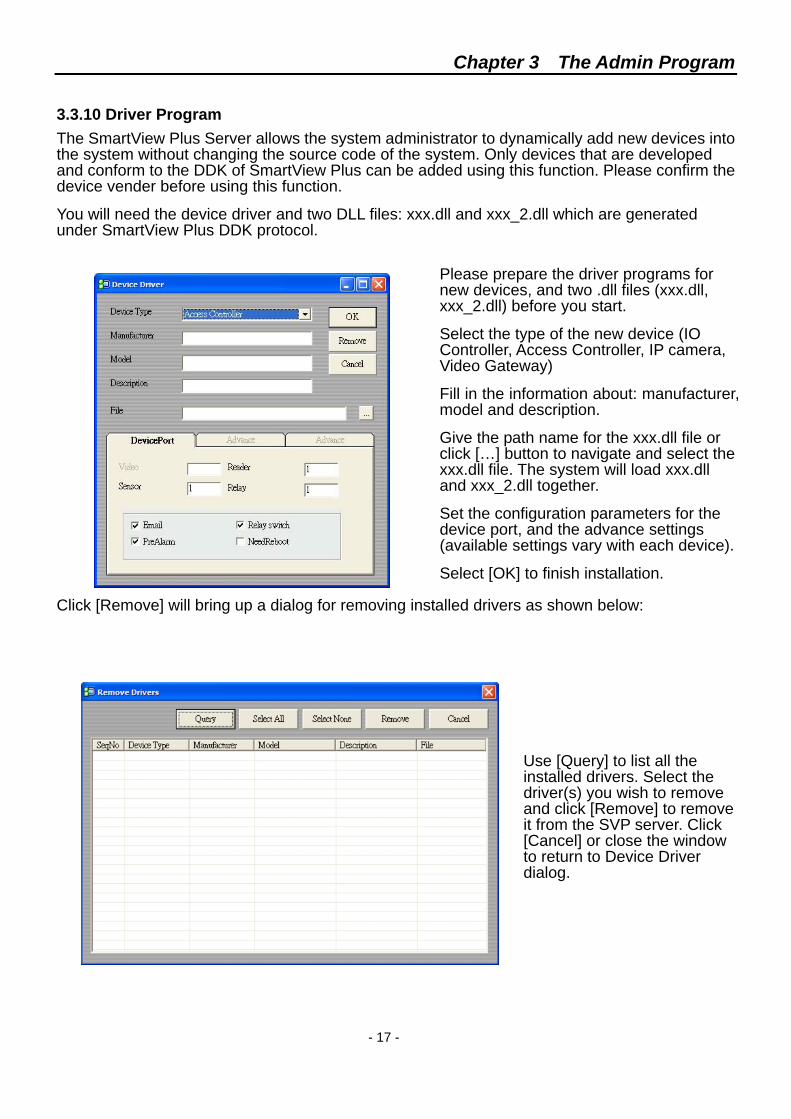
3.3.10 Driver Program The SmartView Plus Server allows the system administrator to dynamically add new devices into the system without changing the source code of the system. Only devices that are developed and conform to the DDK of SmartView Plus can be added using this function. Please confirm the device vender before using this function.
You will need the device driver and two DLL files: xxx.dll and xxx_2.dll which are generated under SmartView Plus DDK protocol.
Please prepare the driver programs for new devices, and two .dll files (xxx.dll, xxx_2.dll) before you start.
Select the type of the new device (IO Controller, Access Controller, IP camera, Video Gateway)
Fill in the information about: manufacturer, model and description.
Give the path name for the xxx.dll file or click […] button to navigate and select the xxx.dll file. The system will load xxx.dll and xxx_2.dll together.
Set the configuration parameters for the device port, and the advance settings (available settings vary with each device).
Select [OK] to finish installation. Click [Remove] will bring up a dialog for removing installed drivers as shown below:
Use [Query] to list all the installed drivers. Select the driver(s) you wish to remove and click [Remove] to remove it from the SVP server. Click [Cancel] or close the window to return to Device Driver dialog.
Chapter 3 The Admin Program
- 18 -
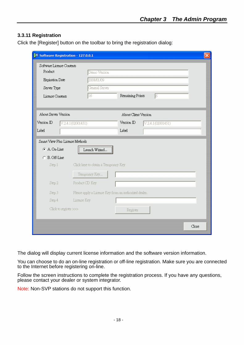
3.3.11 Registration Click the [Register] button on the toolbar to bring the registration dialog:
The dialog will display current license information and the software version information.
You can choose to do an on-line registration or off-line registration. Make sure you are connected to the Internet before registering on-line.
Follow the screen instructions to complete the registration process. If you have any questions, please contact your dealer or system integrator.
Note: Non-SVP stations do not support this function.
Chapter 3 The Admin Program
- 19 -
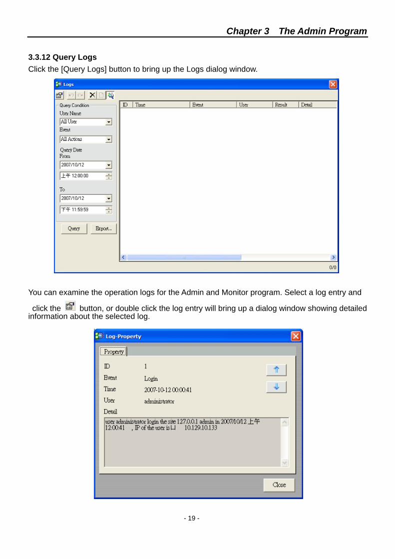
3.3.12 Query Logs Click the [Query Logs] button to bring up the Logs dialog window.
You can examine the operation logs for the Admin and Monitor program. Select a log entry and click the button, or double click the log entry will bring up a dialog window showing detailed information about the selected log.
Chapter 3 The Admin Program
- 20 -
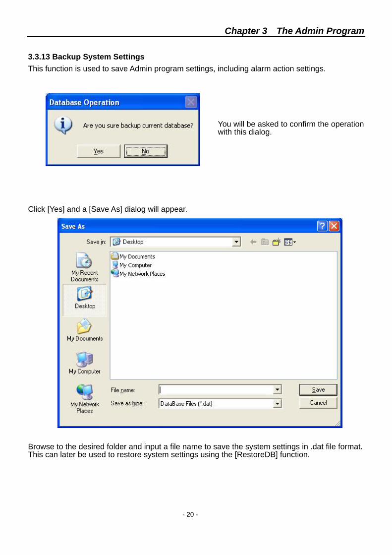
3.3.13 Backup System Settings This function is used to save Admin program settings, including alarm action settings.
You will be asked to confirm the operation with this dialog.
Click [Yes] and a [Save As] dialog will appear. Browse to the desired folder and input a file name to save the system settings in .dat file format. This can later be used to restore system settings using the [RestoreDB] function.
Chapter 3 The Admin Program
- 21 -
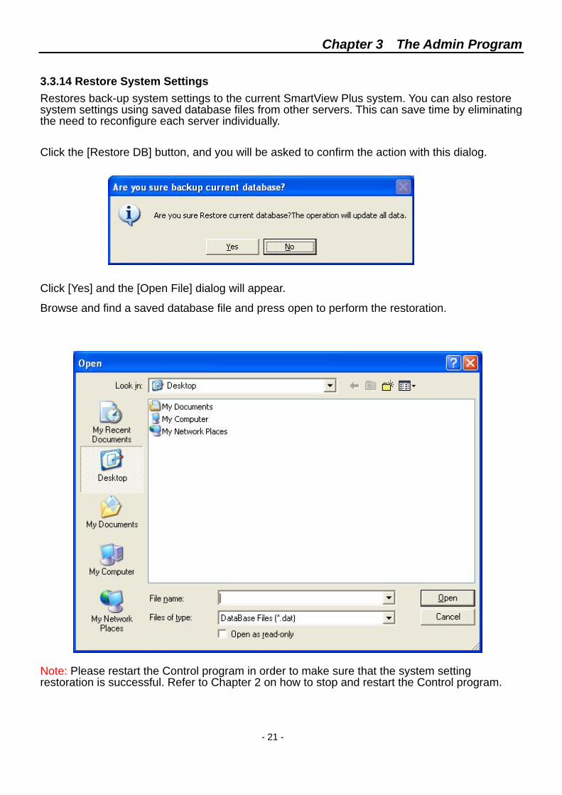
3.3.14 Restore System Settings Restores back-up system settings to the current SmartView Plus system. You can also restore system settings using saved database files from other servers. This can save time by eliminating the need to reconfigure each server individually.
Click the [Restore DB] button, and you will be asked to confirm the action with this dialog. Click [Yes] and the [Open File] dialog will appear.
Browse and find a saved database file and press open to perform the restoration. Note: Please restart the Control program in order to make sure that the system setting restoration is successful. Refer to Chapter 2 on how to stop and restart the Control program.
Chapter 3 The Admin Program
- 22 -
3.4 User Group and User 3.4.1 Buttons Overview Privilege control in SmartView Plus server is implemented through User and User Group architecture. User Group is the basic privilege authorization unit. Administrators create and manage groups with different functions and capabilities, thus privileges. By assigning each user to a user group or combination of user groups, the administrator can control the privilege of each user.
The function buttons are:
Button Function Button Function
Add User Add User Group
Modify User Modify User Group
Remove User Remove User Group
The following sections will describe how to setup user groups and users.
3.4.2 User Group Overview There are three default user groups:
(1) Admin: This group has full privileges and can execute all the functions in the SVP system.
(2) Monitor: This group has all the privileges to monitor the system, including: view the videos, query and playback history data, and camera control.
(3) Power: This group can login and inspect all the system settings but can not modify them. It also has the monitor privileges.
The default user groups can not be deleted or modified. You can create more new user groups as described in the following section.
Chapter 3 The Admin Program
- 23 -
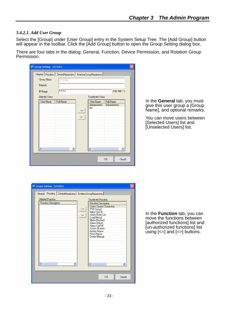
3.4.2.1. Add User Group Select the [Group] under [User Group] entry in the System Setup Tree. The [Add Group] button will appear in the toolbar. Click the [Add Group] button to open the Group Setting dialog box.
There are four tabs in the dialog: General, Function, Device Permission, and Rotation Group Permission.
In the General tab, you must give this user group a [Group Name], and optional remarks.
You can move users between [Selected Users] list and [Unselected Users] list.
In the Function tab, you can move the functions between [authorized functions] list and [un-authorized functions] list using [<=] and [=>] buttons.
Chapter 3 The Admin Program
- 24 -
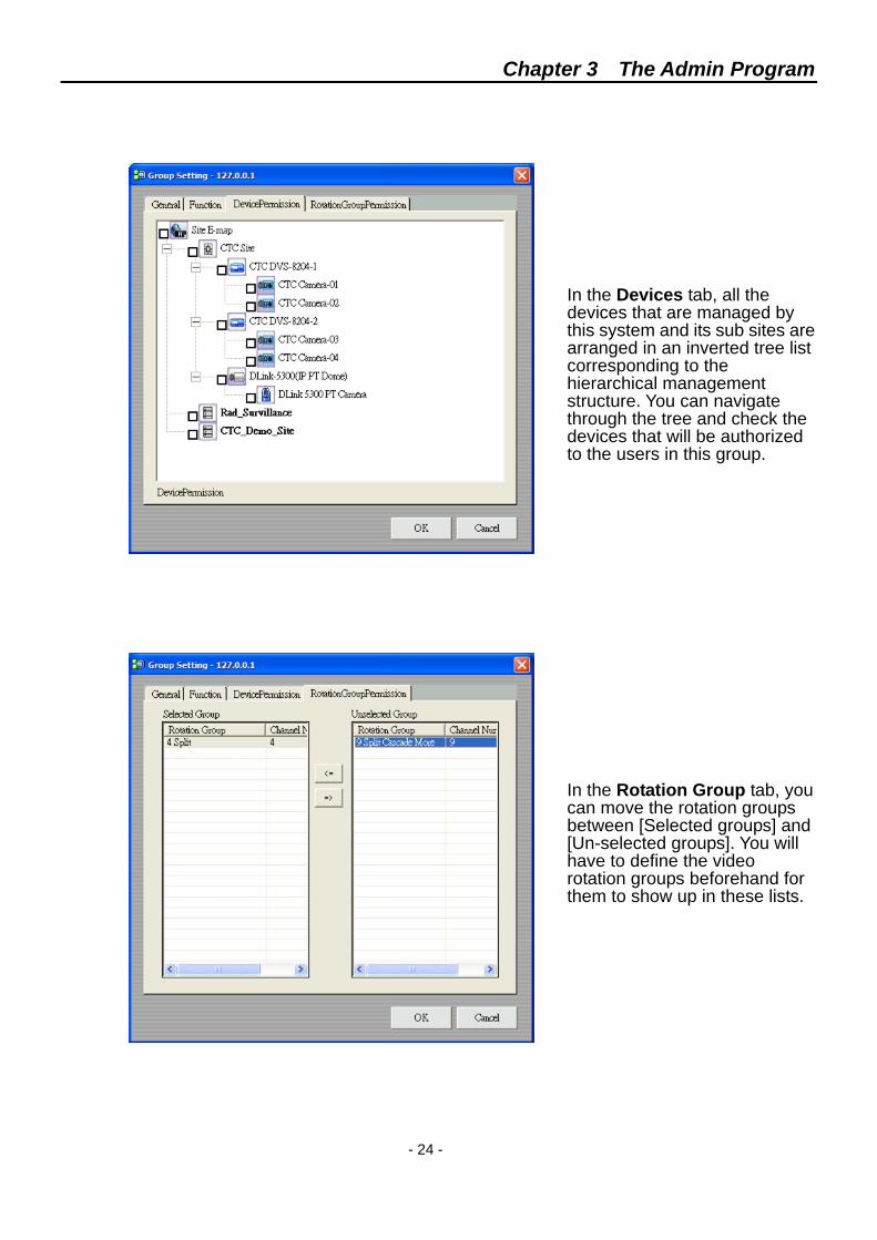
In the Devices tab, all the devices that are managed by this system and its sub sites are arranged in an inverted tree list corresponding to the hierarchical management structure. You can navigate through the tree and check the devices that will be authorized to the users in this group.
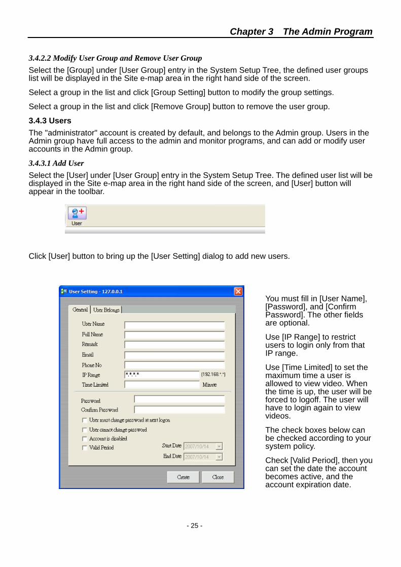
In the Rotation Group tab, you can move the rotation groups between [Selected groups] and [Un-selected groups]. You will have to define the video rotation groups beforehand for them to show up in these lists.
Chapter 3 The Admin Program
- 25 -
3.4.2.2 Modify User Group and Remove User Group Select the [Group] under [User Group] entry in the System Setup Tree, the defined user groups list will be displayed in the Site e-map area in the right hand side of the screen.
Select a group in the list and click [Group Setting] button to modify the group settings.
Select a group in the list and click [Remove Group] button to remove the user group.
3.4.3 Users The "administrator" account is created by default, and belongs to the Admin group. Users in the Admin group have full access to the admin and monitor programs, and can add or modify user accounts in the Admin group.
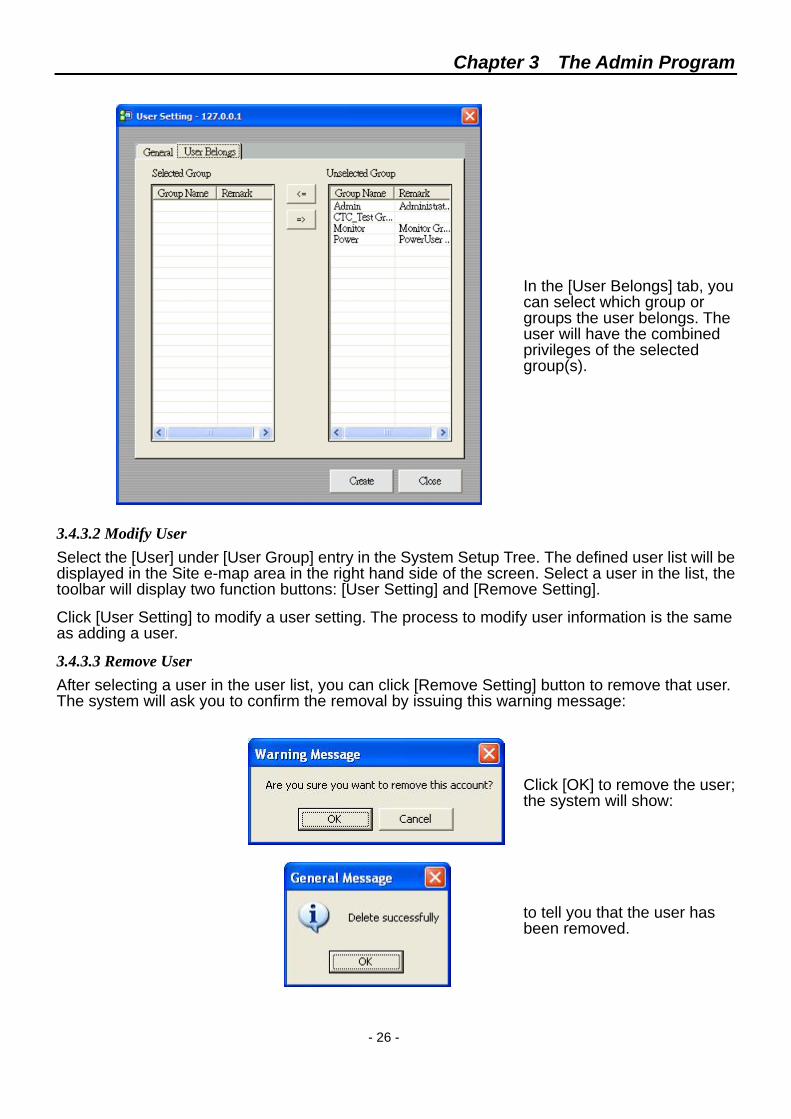
3.4.3.1 Add User Select the [User] under [User Group] entry in the System Setup Tree. The defined user list will be displayed in the Site e-map area in the right hand side of the screen, and [User] button will appear in the toolbar.
Click [User] button to bring up the [User Setting] dialog to add new users.
You must fill in [User Name], [Password], and [Confirm Password]. The other fields are optional.
Use [IP Range] to restrict users to login only from that IP range.
Use [Time Limited] to set the maximum time a user is allowed to view video. When the time is up, the user will be forced to logoff. The user will have to login again to view videos.
The check boxes below can be checked according to your system policy.
Check [Valid Period], then you can set the date the account becomes active, and the account expiration date.
Chapter 3 The Admin Program
- 26 -
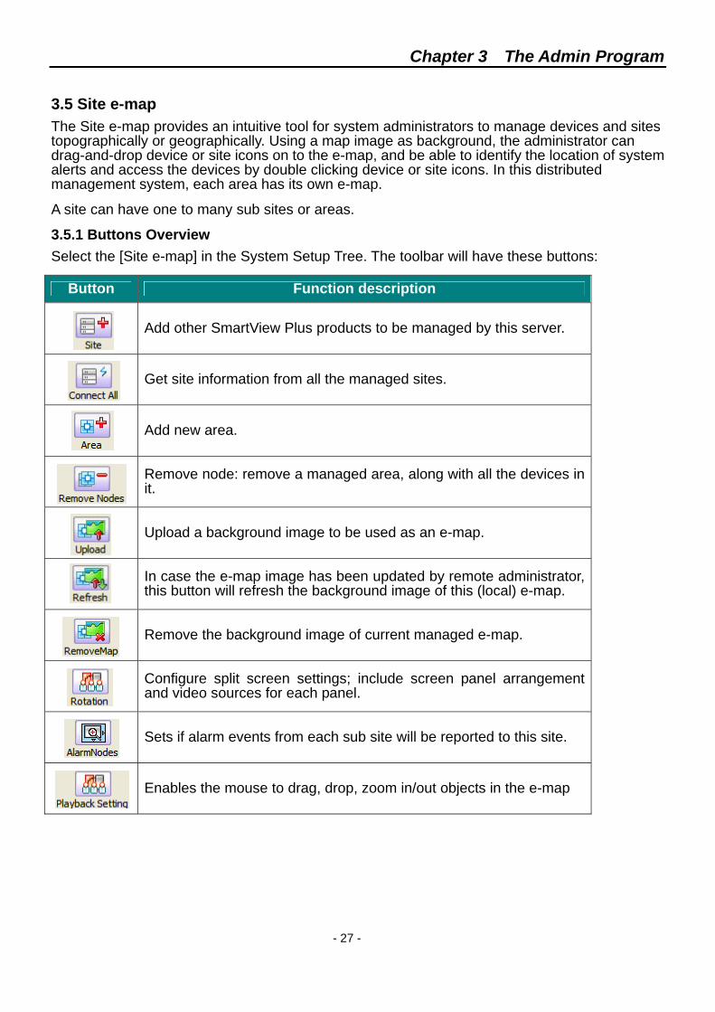
In the [User Belongs] tab, you can select which group or groups the user belongs. The user will have the combined privileges of the selected group(s).
3.4.3.2 Modify User Select the [User] under [User Group] entry in the System Setup Tree. The defined user list will be displayed in the Site e-map area in the right hand side of the screen. Select a user in the list, the toolbar will display two function buttons: [User Setting] and [Remove Setting].
Click [User Setting] to modify a user setting. The process to modify user information is the same as adding a user.
3.4.3.3 Remove User After selecting a user in the user list, you can click [Remove Setting] button to remove that user. The system will ask you to confirm the removal by issuing this warning message:
Click [OK] to remove the user; the system will show:
to tell you that the user has been removed.
Chapter 3 The Admin Program
- 27 -
3.5 Site e-map The Site e-map provides an intuitive tool for system administrators to manage devices and sites topographically or geographically. Using a map image as background, the administrator can drag-and-drop device or site icons on to the e-map, and be able to identify the location of system alerts and access the devices by double clicking device or site icons. In this distributed management system, each area has its own e-map.
A site can have one to many sub sites or areas.
3.5.1 Buttons Overview Select the [Site e-map] in the System Setup Tree. The toolbar will have these buttons:
Button Function description
Add other SmartView Plus products to be managed by this server.
Get site information from all the managed sites.
Add new area.
Remove node: remove a managed area, along with all the devices in it.
Upload a background image to be used as an e-map.
In case the e-map image has been updated by remote administrator, this button will refresh the background image of this (local) e-map.
Remove the background image of current managed e-map.
Configure split screen settings; include screen panel arrangement and video sources for each panel.
Sets if alarm events from each sub site will be reported to this site.
Enables the mouse to drag, drop, zoom in/out objects in the e-map
Chapter 3 The Admin Program
- 28 -
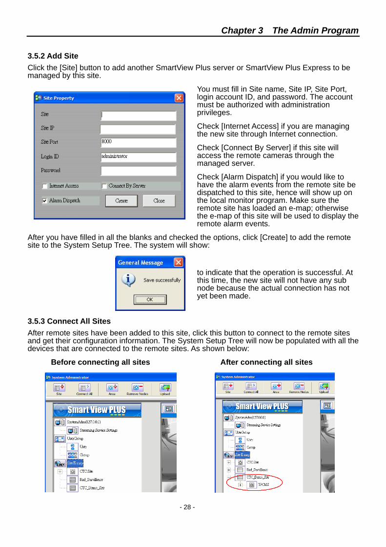
3.5.2 Add Site Click the [Site] button to add another SmartView Plus server or SmartView Plus Express to be managed by this site.
You must fill in Site name, Site IP, Site Port, login account ID, and password. The account must be authorized with administration privileges.
Check [Internet Access] if you are managing the new site through Internet connection.
Check [Connect By Server] if this site will access the remote cameras through the managed server.
Check [Alarm Dispatch] if you would like to have the alarm events from the remote site be dispatched to this site, hence will show up on the local monitor program. Make sure the remote site has loaded an e-map; otherwise the e-map of this site will be used to display the remote alarm events.
After you have filled in all the blanks and checked the options, click [Create] to add the remote site to the System Setup Tree. The system will show:
to indicate that the operation is successful. At this time, the new site will not have any sub node because the actual connection has not yet been made.
3.5.3 Connect All Sites After remote sites have been added to this site, click this button to connect to the remote sites and get their configuration information. The System Setup Tree will now be populated with all the devices that are connected to the remote sites. As shown below:
Before connecting all sites After connecting all sites
Chapter 3 The Admin Program
- 29 -
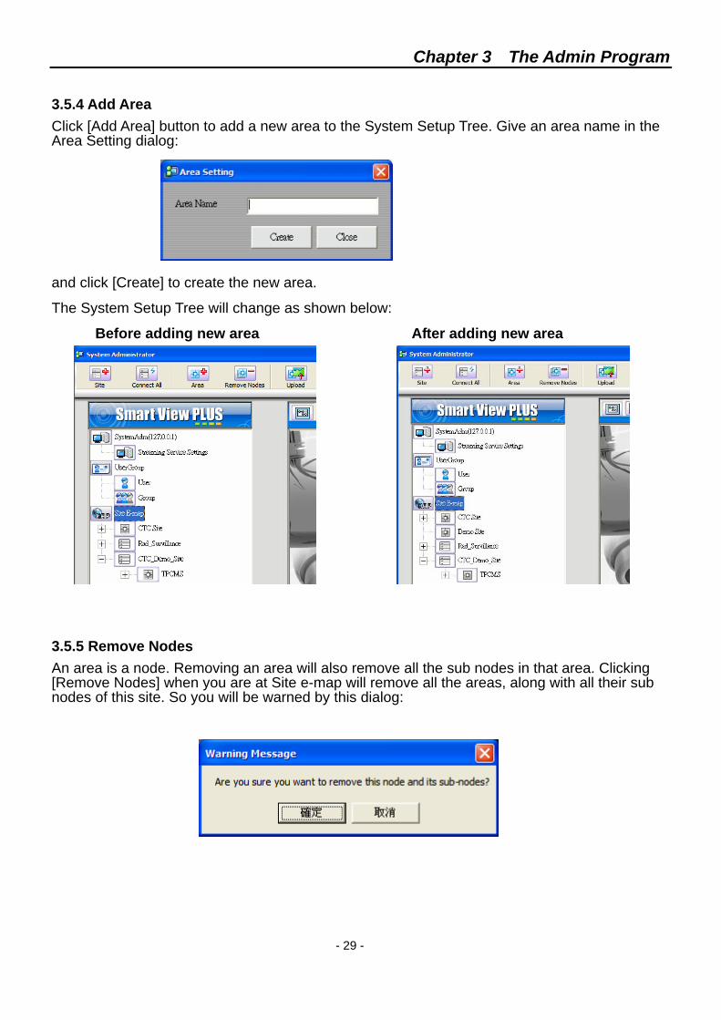
3.5.4 Add Area Click [Add Area] button to add a new area to the System Setup Tree. Give an area name in the Area Setting dialog:
and click [Create] to create the new area.
The System Setup Tree will change as shown below:
Before adding new area After adding new area 3.5.5 Remove Nodes An area is a node. Removing an area will also remove all the sub nodes in that area. Clicking [Remove Nodes] when you are at Site e-map will remove all the areas, along with all their sub nodes of this site. So you will be warned by this dialog:
Chapter 3 The Admin Program
- 30 -
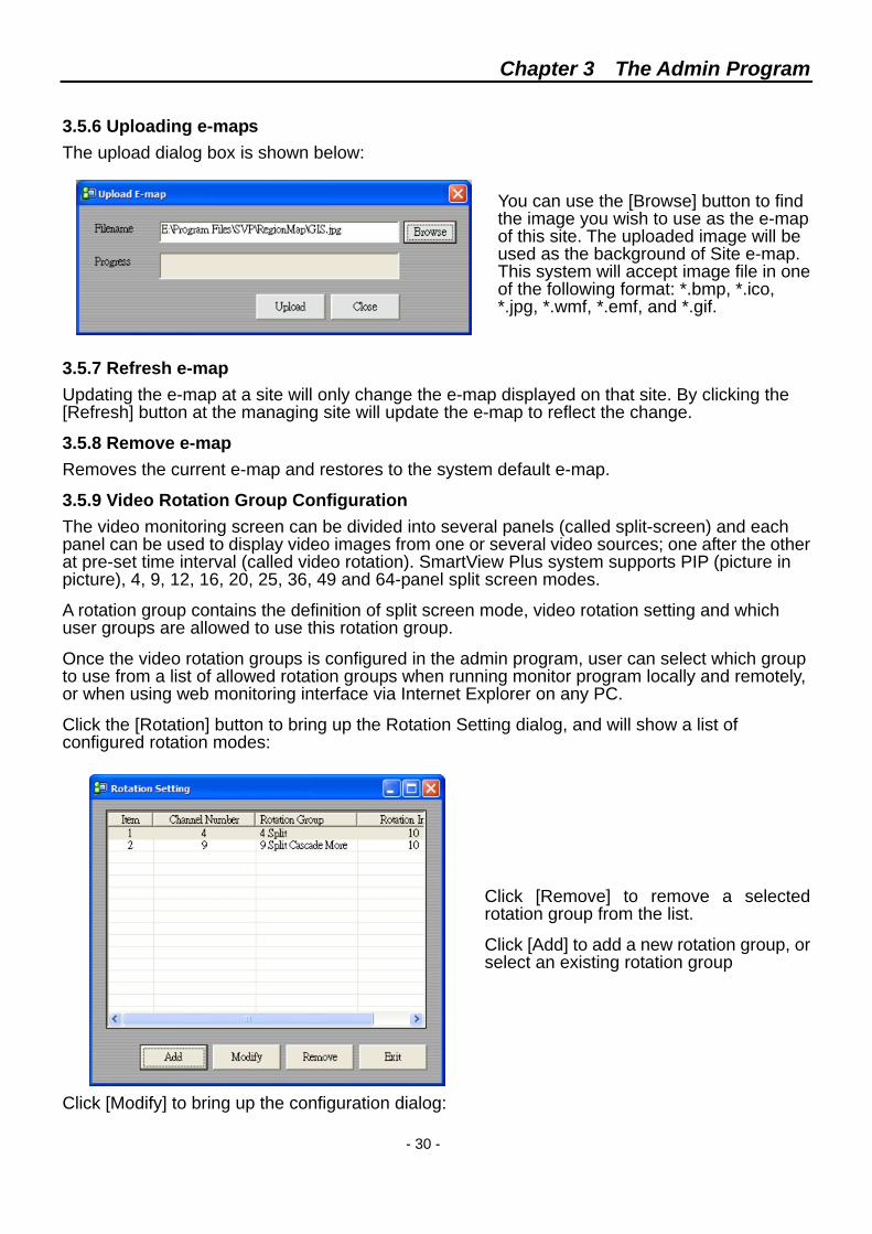
3.5.6 Uploading e-maps The upload dialog box is shown below:
You can use the [Browse] button to find the image you wish to use as the e-map of this site. The uploaded image will be used as the background of Site e-map. This system will accept image file in one of the following format: *.bmp, *.ico, *.jpg, *.wmf, *.emf, and *.gif.
3.5.7 Refresh e-map Updating the e-map at a site will only change the e-map displayed on that site. By clicking the [Refresh] button at the managing site will update the e-map to reflect the change.
3.5.8 Remove e-map Removes the current e-map and restores to the system default e-map.
3.5.9 Video Rotation Group Configuration The video monitoring screen can be divided into several panels (called split-screen) and each panel can be used to display video images from one or several video sources; one after the other at pre-set time interval (called video rotation). SmartView Plus system supports PIP (picture in picture), 4, 9, 12, 16, 20, 25, 36, 49 and 64-panel split screen modes.
A rotation group contains the definition of split screen mode, video rotation setting and which user groups are allowed to use this rotation group.
Once the video rotation groups is configured in the admin program, user can select which group to use from a list of allowed rotation groups when running monitor program locally and remotely, or when using web monitoring interface via Internet Explorer on any PC.
Click the [Rotation] button to bring up the Rotation Setting dialog, and will show a list of configured rotation modes:
Click [Remove] to remove a selected rotation group from the list.
Click [Add] to add a new rotation group, or select an existing rotation group
Click [Modify] to bring up the configuration dialog:
Chapter 3 The Admin Program
- 31 -
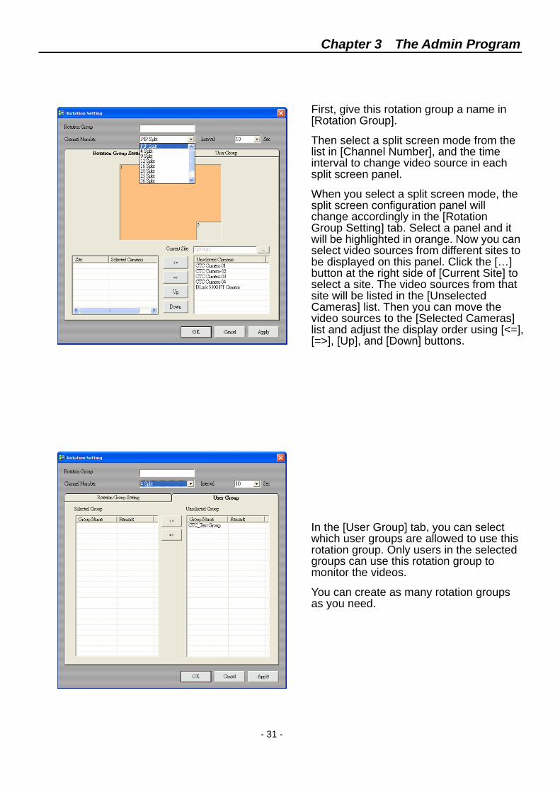
First, give this rotation group a name in [Rotation Group].
Then select a split screen mode from the list in [Channel Number], and the time interval to change video source in each split screen panel.
When you select a split screen mode, the split screen configuration panel will change accordingly in the [Rotation Group Setting] tab. Select a panel and it will be highlighted in orange. Now you can select video sources from different sites to be displayed on this panel. Click the […] button at the right side of [Current Site] to select a site. The video sources from that site will be listed in the [Unselected Cameras] list. Then you can move the video sources to the [Selected Cameras] list and adjust the display order using [<=], [=>], [Up], and [Down] buttons.
In the [User Group] tab, you can select which user groups are allowed to use this rotation group. Only users in the selected groups can use this rotation group to monitor the videos.
You can create as many rotation groups as you need.
Chapter 3 The Admin Program
- 32 -
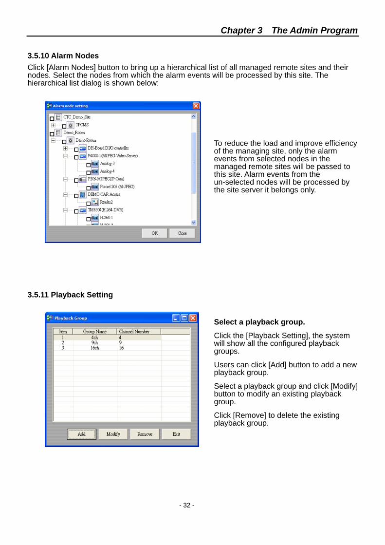
3.5.10 Alarm Nodes Click [Alarm Nodes] button to bring up a hierarchical list of all managed remote sites and their nodes. Select the nodes from which the alarm events will be processed by this site. The hierarchical list dialog is shown below:
To reduce the load and improve efficiency of the managing site, only the alarm events from selected nodes in the managed remote sites will be passed to this site. Alarm events from the un-selected nodes will be processed by the site server it belongs only.
3.5.11 Playback Setting
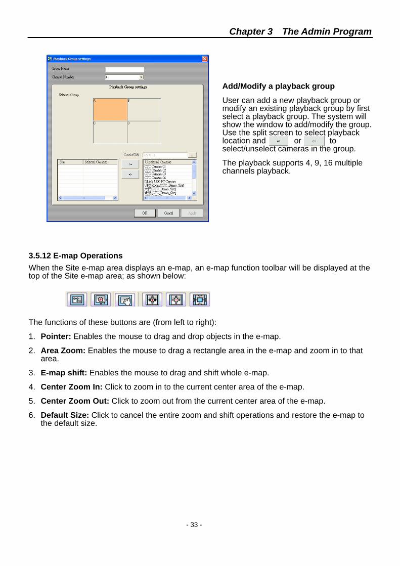
Select a playback group.
Click the [Playback Setting], the system will show all the configured playback groups.
Users can click [Add] button to add a new playback group.
Select a playback group and click [Modify] button to modify an existing playback group.
Click [Remove] to delete the existing playback group.
Chapter 3 The Admin Program
- 33 -
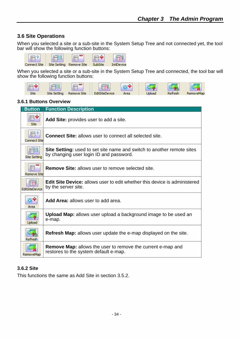
Add/Modify a playback group
User can add a new playback group or modify an existing playback group by first select a playback group. The system will show the window to add/modify the group. Use the split screen to select playback location and or to select/unselect cameras in the group.
The playback supports 4, 9, 16 multiple channels playback.
3.5.12 E-map Operations When the Site e-map area displays an e-map, an e-map function toolbar will be displayed at the top of the Site e-map area; as shown below:
The functions of these buttons are (from left to right):
1. Pointer: Enables the mouse to drag and drop objects in the e-map.
2. Area Zoom: Enables the mouse to drag a rectangle area in the e-map and zoom in to that area.
3. E-map shift: Enables the mouse to drag and shift whole e-map.
4. Center Zoom In: Click to zoom in to the current center area of the e-map.
5. Center Zoom Out: Click to zoom out from the current center area of the e-map.
6. Default Size: Click to cancel the entire zoom and shift operations and restore the e-map to the default size.
Chapter 3 The Admin Program
- 34 -
3.6 Site Operations When you selected a site or a sub-site in the System Setup Tree and not connected yet, the tool bar will show the following function buttons:
When you selected a site or a sub-site in the System Setup Tree and connected, the tool bar will show the following function buttons:
3.6.1 Buttons Overview
Button Function Description
Add Site: provides user to add a site.
Connect Site: allows user to connect all selected site.
Site Setting: used to set site name and switch to another remote sites by changing user login ID and password.
Remove Site: allows user to remove selected site.
Edit Site Device: allows user to edit whether this device is administered by the server site.
Add Area: allows user to add area.
Upload Map: allows user upload a background image to be used an e-map.
Refresh Map: allows user update the e-map displayed on the site.
Remove Map: allows the user to remove the current e-map and restores to the system default e-map.
3.6.2 Site This functions the same as Add Site in section 3.5.2.
Chapter 3 The Admin Program
- 35 -
3.6.3 Connect All
Before user click [Connect Site] button, system will not connect server automatically.
Click [Connect Site] button to connect to the server, if the server exists, the System Setup Tree will be populated with all the devices that are connected to the server site.
If the server does not exist, the system will show the left error message dialog box, tell user that unable to connect server.
3.6.4 Site Settings
[Site Settings] button used to set site name and switch to other remote sites by changing user login ID and password.
Click [Site Settings] button, the system will show the left dialog box, Site IP and Site Port are unmodifiable. User can modify Site name, Login ID, Password and check/uncheck the [Internet Access], [Connect by Server], or [Alarm Dispatch] checkbox.
Note: For site name, please do not use full-form character of number set.
3.6.5 Remove Site
Clicking [Remove Site] will remove the node and its sub-nodes, so user will be warned by the left dialog box.
If user clicks [Yes], user can not manage its sub-nodes afterward.
After remove site, user can not undo this action, please make sure before you remove any site.
Chapter 3 The Admin Program
- 36 -
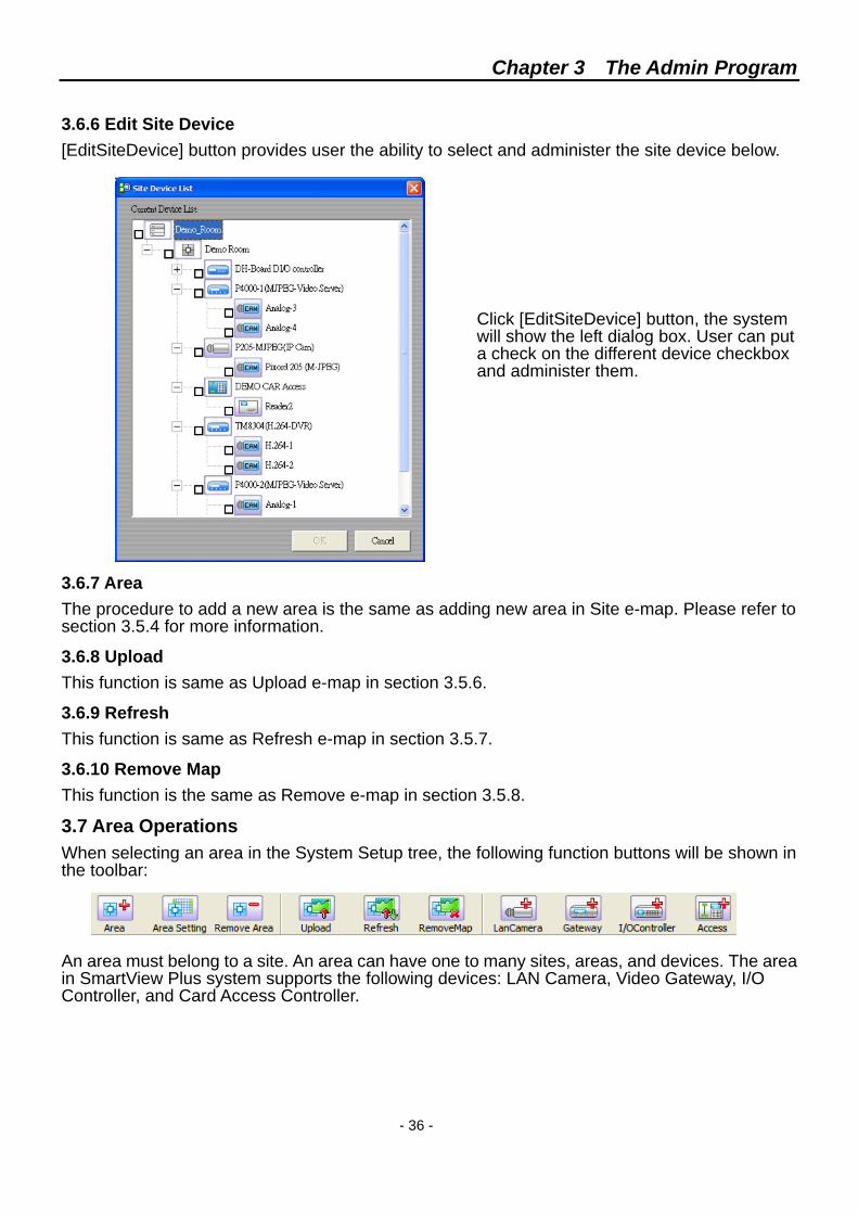
3.6.6 Edit Site Device [EditSiteDevice] button provides user the ability to select and administer the site device below.
Click [EditSiteDevice] button, the system will show the left dialog box. User can put a check on the different device checkbox and administer them.
3.6.7 Area The procedure to add a new area is the same as adding new area in Site e-map. Please refer to section 3.5.4 for more information.
3.6.8 Upload This function is same as Upload e-map in section 3.5.6.
3.6.9 Refresh This function is same as Refresh e-map in section 3.5.7.
3.6.10 Remove Map This function is the same as Remove e-map in section 3.5.8.
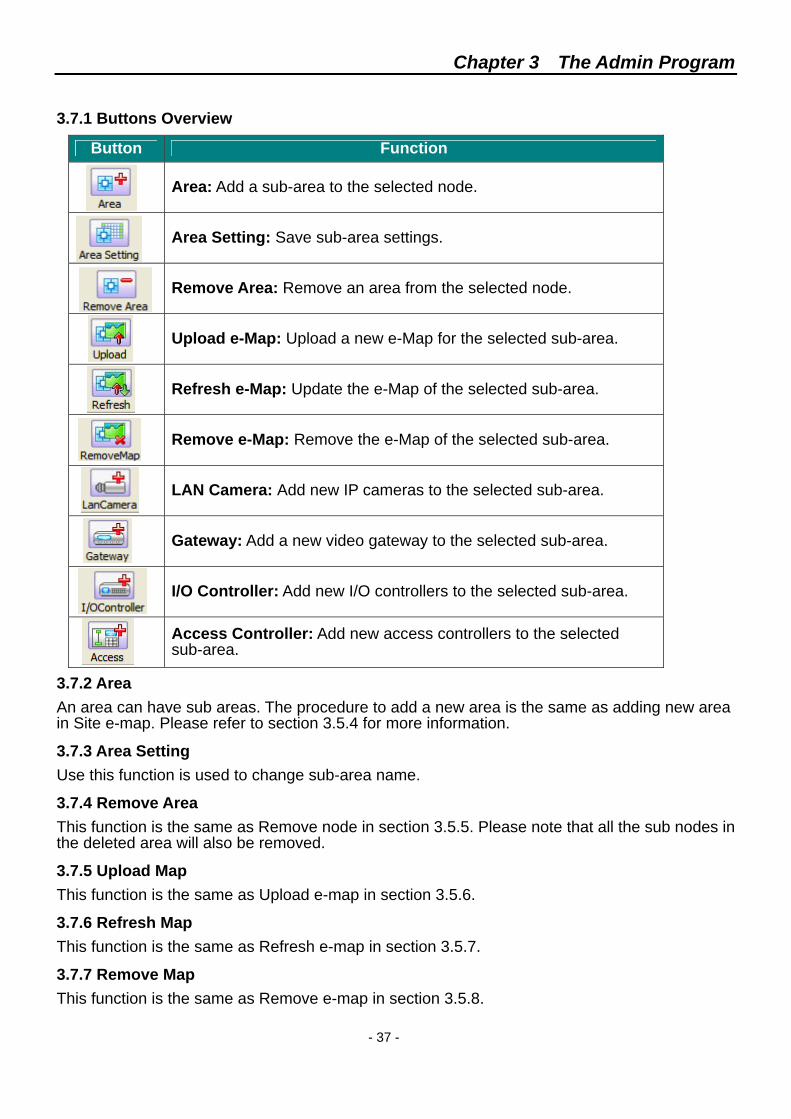
3.7 Area Operations When selecting an area in the System Setup tree, the following function buttons will be shown in the toolbar:
An area must belong to a site. An area can have one to many sites, areas, and devices. The area in SmartView Plus system supports the following devices: LAN Camera, Video Gateway, I/O Controller, and Card Access Controller.
Chapter 3 The Admin Program
- 37 -
3.7.1 Buttons Overview
Button Function
Area: Add a sub-area to the selected node.
Area Setting: Save sub-area settings.
Remove Area: Remove an area from the selected node.
Upload e-Map: Upload a new e-Map for the selected sub-area.
Refresh e-Map: Update the e-Map of the selected sub-area.
Remove e-Map: Remove the e-Map of the selected sub-area.
LAN Camera: Add new IP cameras to the selected sub-area.
Gateway: Add a new video gateway to the selected sub-area.
I/O Controller: Add new I/O controllers to the selected sub-area.
Access Controller: Add new access controllers to the selected sub-area.
3.7.2 Area An area can have sub areas. The procedure to add a new area is the same as adding new area in Site e-map. Please refer to section 3.5.4 for more information.
3.7.3 Area Setting Use this function is used to change sub-area name.
3.7.4 Remove Area This function is the same as Remove node in section 3.5.5. Please note that all the sub nodes in the deleted area will also be removed.
3.7.5 Upload Map This function is the same as Upload e-map in section 3.5.6.
3.7.6 Refresh Map This function is the same as Refresh e-map in section 3.5.7.
3.7.7 Remove Map This function is the same as Remove e-map in section 3.5.8.
Chapter 3 The Admin Program
- 38 -
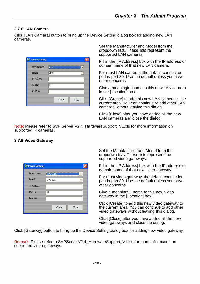
3.7.8 LAN Camera Click [LAN Camera] button to bring up the Device Setting dialog box for adding new LAN cameras.
Set the Manufacturer and Model from the dropdown lists. These lists represent the supported LAN cameras.
Fill in the [IP Address] box with the IP address or domain name of that new LAN camera.
For most LAN cameras, the default connection port is port 80. Use the default unless you have other concerns.
Give a meaningful name to this new LAN camera in the [Location] box.
Click [Create] to add this new LAN camera to the current area. You can continue to add other LAN cameras without leaving this dialog.
Click [Close] after you have added all the new LAN cameras and close the dialog.
Note: Please refer to SVP Server V2.4_HardwareSupport_V1.xls for more information on supported IP cameras. 3.7.9 Video Gateway
Set the Manufacturer and Model from the dropdown lists. These lists represent the supported video gateways.
Fill in the [IP Address] box with the IP address or domain name of that new video gateway.
For most video gateway, the default connection port is port 80. Use the default unless you have other concerns.
Give a meaningful name to this new video gateway in the [Location] box.
Click [Create] to add this new video gateway to the current area. You can continue to add other video gateways without leaving this dialog.
Click [Close] after you have added all the new video gateways and close the dialog.
Click [Gateway] button to bring up the Device Setting dialog box for adding new video gateway.
Remark: Please refer to SVPServerV2.4_HardwareSupport_V1.xls for more information on supported video gateways.
Chapter 3 The Admin Program
- 39 -
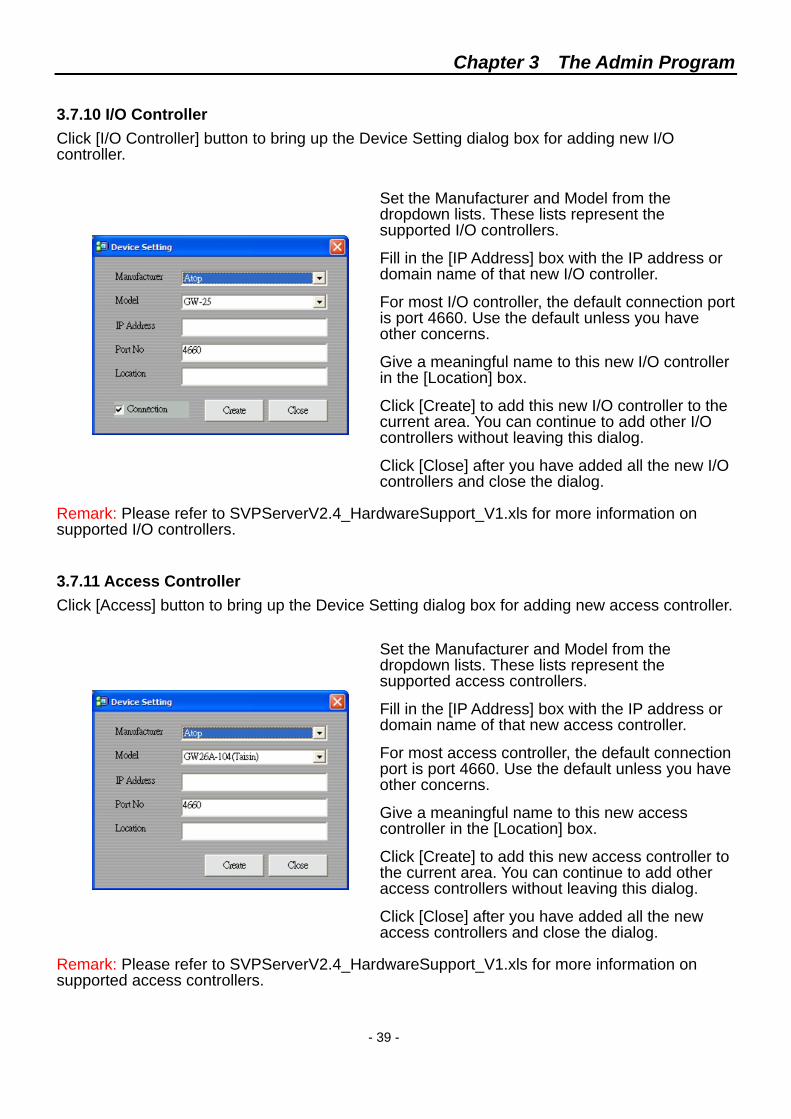
3.7.10 I/O Controller Click [I/O Controller] button to bring up the Device Setting dialog box for adding new I/O controller.
Set the Manufacturer and Model from the dropdown lists. These lists represent the supported I/O controllers.
Fill in the [IP Address] box with the IP address or domain name of that new I/O controller.
For most I/O controller, the default connection port is port 4660. Use the default unless you have other concerns.
Give a meaningful name to this new I/O controller in the [Location] box.
Click [Create] to add this new I/O controller to the current area. You can continue to add other I/O controllers without leaving this dialog.
Click [Close] after you have added all the new I/O controllers and close the dialog.
Remark: Please refer to SVPServerV2.4_HardwareSupport_V1.xls for more information on supported I/O controllers.
3.7.11 Access Controller Click [Access] button to bring up the Device Setting dialog box for adding new access controller.
Set the Manufacturer and Model from the dropdown lists. These lists represent the supported access controllers.
Fill in the [IP Address] box with the IP address or domain name of that new access controller.
For most access controller, the default connection port is port 4660. Use the default unless you have other concerns.
Give a meaningful name to this new access controller in the [Location] box.
Click [Create] to add this new access controller to the current area. You can continue to add other access controllers without leaving this dialog.
Click [Close] after you have added all the new access controllers and close the dialog.
Remark: Please refer to SVPServerV2.4_HardwareSupport_V1.xls for more information on supported access controllers.
Chapter 3 The Admin Program
- 40 -
3.8 Devices and Device Configuration When a device is selected in the System Setup tree, function buttons corresponding to the device type will appear in the toolbar.
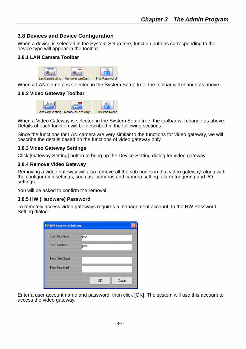
3.8.1 LAN Camera Toolbar When a LAN Camera is selected in the System Setup tree, the toolbar will change as above.
3.8.2 Video Gateway Toolbar When a Video Gateway is selected in the System Setup tree, the toolbar will change as above. Details of each function will be described in the following sections.
Since the functions for LAN camera are very similar to the functions for video gateway, we will describe the details based on the functions of video gateway only.
3.8.3 Video Gateway Settings Click [Gateway Setting] button to bring up the Device Setting dialog for video gateway.
3.8.4 Remove Video Gateway Removing a video gateway will also remove all the sub nodes in that video gateway, along with the configuration settings, such as: cameras and camera setting, alarm triggering and I/O settings.
You will be asked to confirm the removal.
3.8.5 HW (Hardware) Password To remotely access video gateways requires a management account. In the HW Password Setting dialog:
Enter a user account name and password, then click [OK]. The system will use this account to access the video gateway.
Chapter 3 The Admin Program
- 41 -
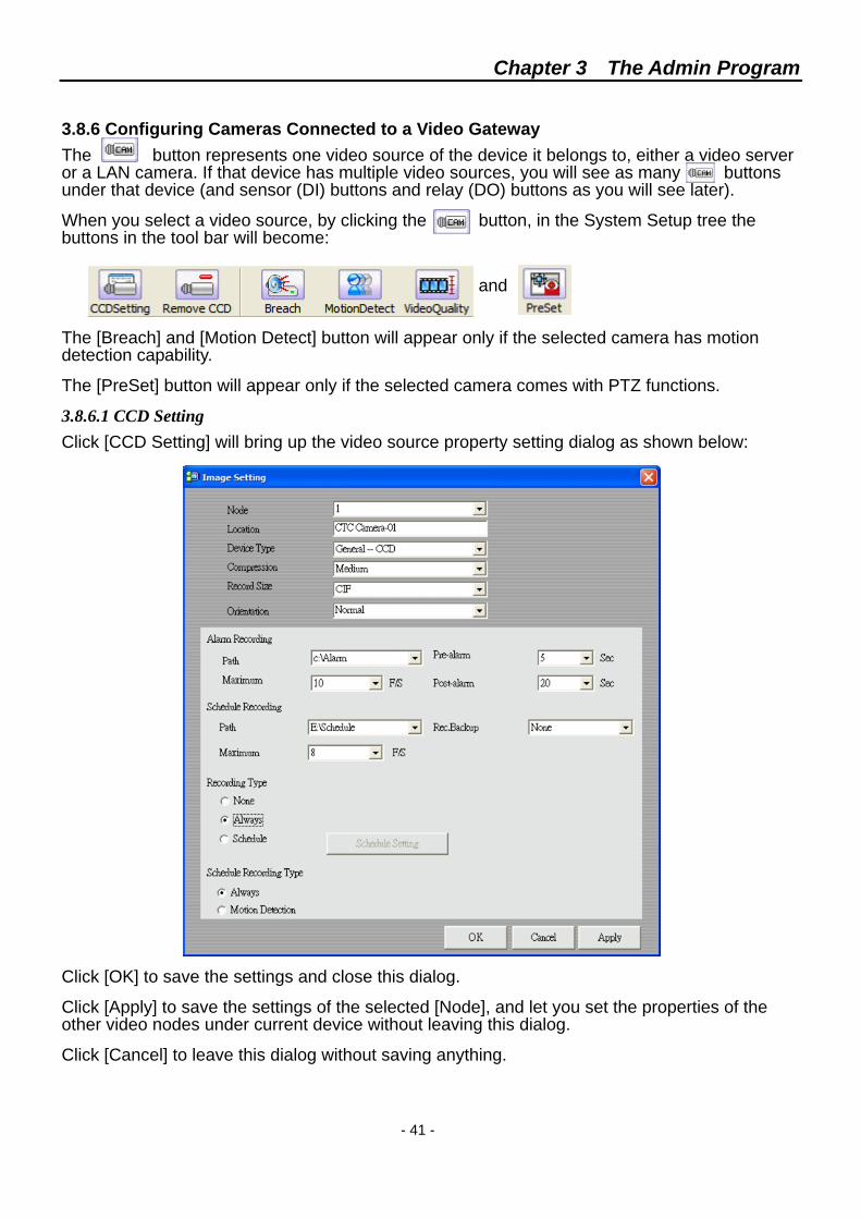
3.8.6 Configuring Cameras Connected to a Video Gateway The button represents one video source of the device it belongs to, either a video server or a LAN camera. If that device has multiple video sources, you will see as many buttons under that device (and sensor (DI) buttons and relay (DO) buttons as you will see later).
When you select a video source, by clicking the button, in the System Setup tree the buttons in the tool bar will become:
and The [Breach] and [Motion Detect] button will appear only if the selected camera has motion detection capability.
The [PreSet] button will appear only if the selected camera comes with PTZ functions.
3.8.6.1 CCD Setting Click [CCD Setting] will bring up the video source property setting dialog as shown below:
Click [OK] to save the settings and close this dialog.
Click [Apply] to save the settings of the selected [Node], and let you set the properties of the other video nodes under current device without leaving this dialog.
Click [Cancel] to leave this dialog without saving anything.
Chapter 3 The Admin Program
- 42 -
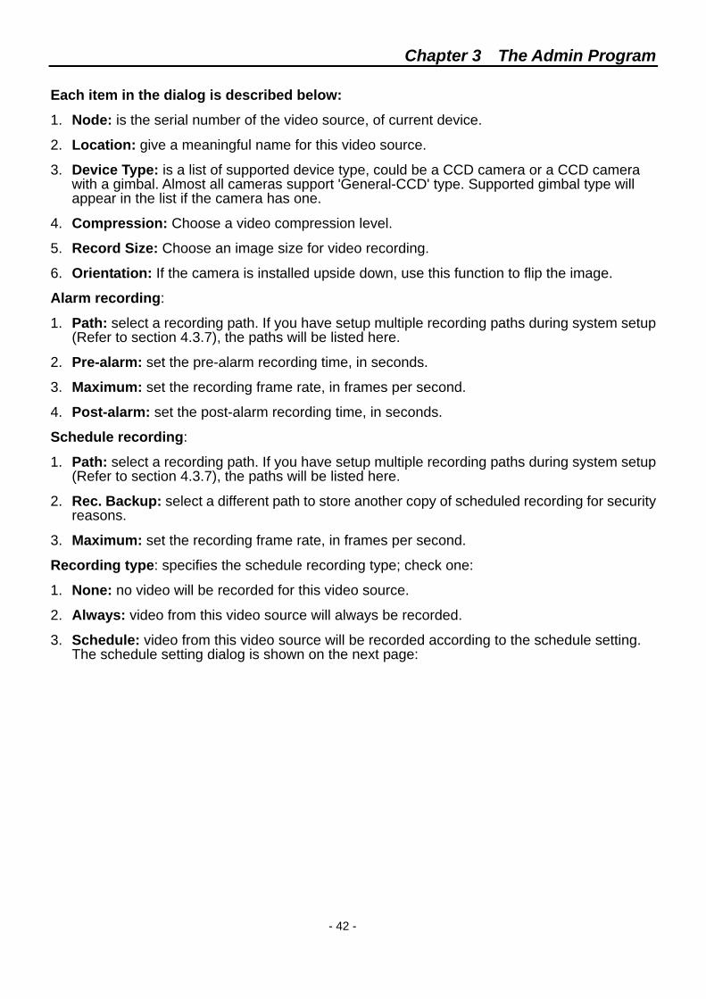
Each item in the dialog is described below:
1. Node: is the serial number of the video source, of current device.
2. Location: give a meaningful name for this video source.
3. Device Type: is a list of supported device type, could be a CCD camera or a CCD camera with a gimbal. Almost all cameras support 'General-CCD' type. Supported gimbal type will appear in the list if the camera has one.
4. Compression: Choose a video compression level.
5. Record Size: Choose an image size for video recording.
6. Orientation: If the camera is installed upside down, use this function to flip the image.
Alarm recording:
1. Path: select a recording path. If you have setup multiple recording paths during system setup (Refer to section 4.3.7), the paths will be listed here.
2. Pre-alarm: set the pre-alarm recording time, in seconds.
3. Maximum: set the recording frame rate, in frames per second.
4. Post-alarm: set the post-alarm recording time, in seconds.
Schedule recording:
1. Path: select a recording path. If you have setup multiple recording paths during system setup (Refer to section 4.3.7), the paths will be listed here.
2. Rec. Backup: select a different path to store another copy of scheduled recording for security reasons.
3. Maximum: set the recording frame rate, in frames per second.
Recording type: specifies the schedule recording type; check one:
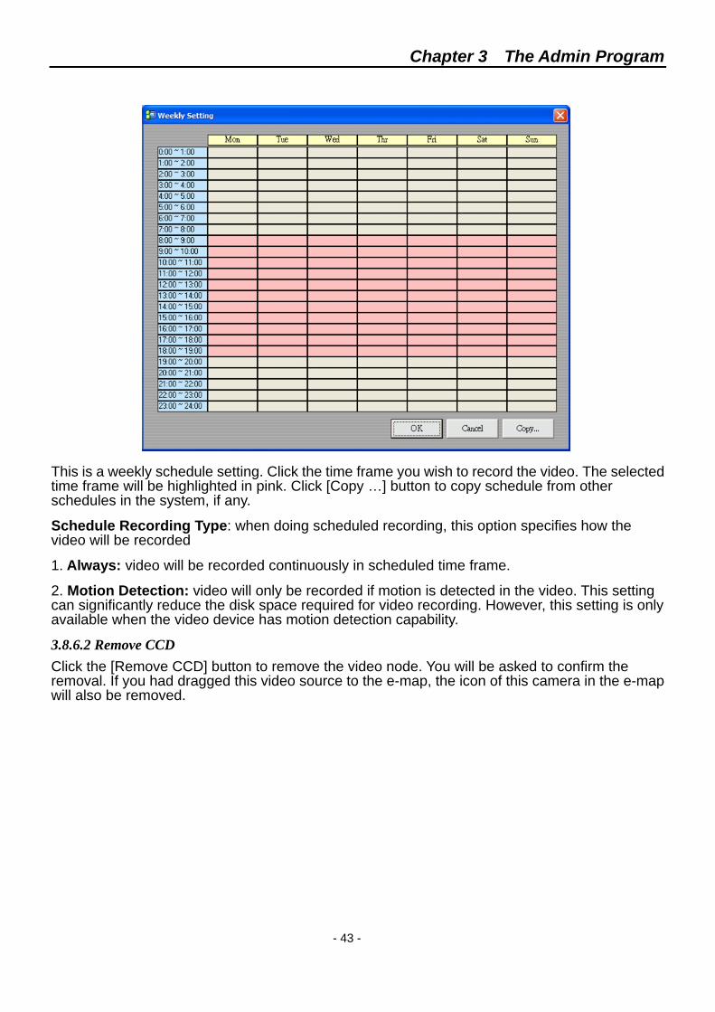
1. None: no video will be recorded for this video source.
2. Always: video from this video source will always be recorded.
3. Schedule: video from this video source will be recorded according to the schedule setting. The schedule setting dialog is shown on the next page:
Chapter 3 The Admin Program
- 43 -
This is a weekly schedule setting. Click the time frame you wish to record the video. The selected time frame will be highlighted in pink. Click [Copy …] button to copy schedule from other schedules in the system, if any.
Schedule Recording Type: when doing scheduled recording, this option specifies how the video will be recorded
1. Always: video will be recorded continuously in scheduled time frame.
2. Motion Detection: video will only be recorded if motion is detected in the video. This setting can significantly reduce the disk space required for video recording. However, this setting is only available when the video device has motion detection capability.
3.8.6.2 Remove CCD Click the [Remove CCD] button to remove the video node. You will be asked to confirm the removal. If you had dragged this video source to the e-map, the icon of this camera in the e-map will also be removed.
Chapter 3 The Admin Program
- 44 -
3.8.6.3 Breach Click [Breach] button will bring up the Alarm Action (alarm trigger) setting dialog, as shown below:
This dialog has two sections: one is to set when to carry out alarm actions, the other is a list of alarm actions and buttons to configure the alarm actions (triggers).
1. Disable: Deactivates alarm actions.
2. Always: Always carry out alarm actions.
3. Schedule: Carry out alarm actions in scheduled time frame.
4. Holiday: Check this box to activate alarm actions during holidays.
5. Alarm Interval: Treat all the alarm events within this time interval as a single alarm.
Setting alarm actions activation schedule is the same as setting the schedule for scheduled recording, as described in last section.
The procedure to create alarm actions is the same as creating alarm action for system alarms, only the alarm type becomes 'Motion Detect'.
Click [Copy …] button to copy alarm action list from other devices, if any. This can save some effort in setting up the alarm action list.
Chapter 3 The Admin Program
- 45 -
There are additional alarm actions for 'Motion Detect' alarm type. They are: 'LiveVideo', 'PreSet', and 'Recording'. The Alarm Action dialog changes accordingly as shown below:
For 'LiveVideo', the [Location] specifies which video will pop up in the monitor program to notify the operator.
For 'PreSet', the [Location] specifies the video source with gimbal, and [Preset] specifies which preset position the gimbal should turn to.
For 'Recording', the [Location] specifies which video source will be recorded.
3.8.6.4 Motion Detection Click [Motion Detect] button to bring up the motion detection setup dialog. A typical motion detection dialog is shown below:
Different camera may have different interface for motion detection adjustment. Some may require you to install Active-X components for that purpose. (Such as Axis 2120)
Red boxes in the above dialog represent areas where changes will be detected. Click on the picture to toggle the red boxes on or off.
Use the sliders to adjust detection sensitivity and frequency. Higher sensitivity can detect smaller area change and higher frequency can detect slower movement.
Chapter 3 The Admin Program
- 46 -
3.8.6.5 Video Quality Click the [Video Quality] button to bring up the video quality adjustment dialog, as shown below:
You can use the sliders to adjust contrast, hue, brightness, saturation, and video compression ratio.
Click [Default] to restore to default values
3.8.7 Gimbal Control If a camera has a gimbal, its icon will change from to after "CCD Setting", and the toolbar will have an additional [PreSet] button when the camera is selected.
3.8.7.1 Preset Setting Click the [PreSet] button to bring the Preset Setting dialog for gimbals, as shown below:
Select a [Preset Location] from the dropdown list and give it a meaningful name in [Preset Name].
Adjust the focal length (zooming) using the "-" and "+" magnifier buttons, if the camera has a zoom lens.
Adjust the gimbal direction using the arrow buttons.
Click [Setup] to store this location into the gimbal, if it supports preset location. This will also overwrite the previous setting stored in this preset location. Preset locations can not be removed.
Set the other preset locations in the same manner. Click [Exit] to leave this dialog.
Chapter 3 The Admin Program
- 47 -
3.8.8 Sensor (Digital Input) Many video gateways and LAN cameras have GPIO (General Purpose Input/Output) port. The digital inputs can be connected to sensors, while digital outputs can be connecting to relay switches.
In System Setup tree, a sensor is represented by (un-configured sensor) or (configured sensor) icon, and relay switch is represented by icon.
When you select a sensor in the System Setup tree, the toolbar becomes:
But the two buttons on the right will appear only after a sensor has been configured.
3.8.8.1 Sensor Setting Click the [Sensor Setting] button to bring up the Sensor Setting dialog, as shown below:
1. Node: is the serial number of this sensor of the current device.
2. Location: give a meaningful name to this sensor.
3. Pattern: There are two kinds of sensors: General and Critical. General sensor can be turned on or off by system administrator while critical sensor cannot.
4. Default Status: can be normal open or normal close depend on the sensor type.
5. Enable: check this to activate the sensor.
6. Click [OK] to save the settings and leave this dialog.
7. Click [Apply] to save the settings of this sensor, and stay in this dialog to set the other sensor nodes.
3.8.8.2 Remove Sensor Click [Remove Sensor] to remove the selected sensor. You will be asked to confirm the deletion.
3.8.8.3 Breach The alarm actions are the same as those for LAN camera, with two additional alarm actions: [Enable DI] and [Disable DI].
Chapter 3 The Admin Program
- 48 -
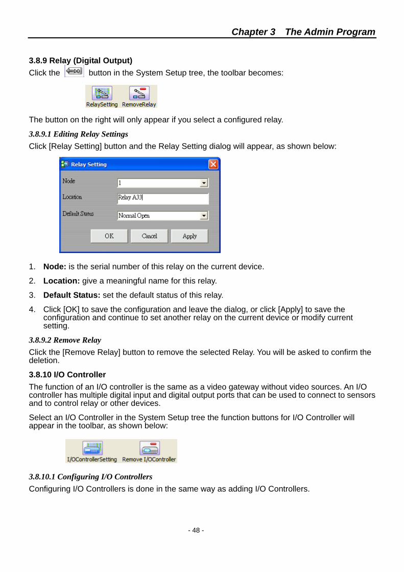
3.8.9 Relay (Digital Output) Click the button in the System Setup tree, the toolbar becomes:
The button on the right will only appear if you select a configured relay.
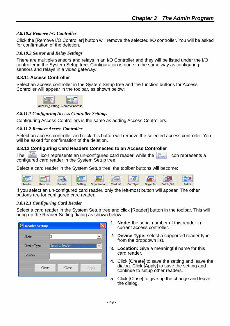
3.8.9.1 Editing Relay Settings Click [Relay Setting] button and the Relay Setting dialog will appear, as shown below:
1. Node: is the serial number of this relay on the current device.
2. Location: give a meaningful name for this relay.
3. Default Status: set the default status of this relay.
4. Click [OK] to save the configuration and leave the dialog, or click [Apply] to save the configuration and continue to set another relay on the current device or modify current setting.
3.8.9.2 Remove Relay Click the [Remove Relay] button to remove the selected Relay. You will be asked to confirm the deletion.
3.8.10 I/O Controller The function of an I/O controller is the same as a video gateway without video sources. An I/O controller has multiple digital input and digital output ports that can be used to connect to sensors and to control relay or other devices.
Select an I/O Controller in the System Setup tree the function buttons for I/O Controller will appear in the toolbar, as shown below:
3.8.10.1 Configuring I/O Controllers Configuring I/O Controllers is done in the same way as adding I/O Controllers.
Chapter 3 The Admin Program
- 49 -
3.8.10.2 Remove I/O Controller Click the [Remove I/O Controller] button will remove the selected I/O controller. You will be asked for confirmation of the deletion.
3.8.10.3 Sensor and Relay Settings There are multiple sensors and relays in an I/O Controller and they will be listed under the I/O controller in the System Setup tree. Configuration is done in the same way as configuring sensors and relays in a video gateway.
3.8.11 Access Controller Select an access controller in the System Setup tree and the function buttons for Access Controller will appear in the toolbar, as shown below:
3.8.11.1 Configuring Access Controller Settings Configuring Access Controllers is the same as adding Access Controllers.
3.8.11.2 Remove Access Controller Select an access controller and click this button will remove the selected access controller. You will be asked for confirmation of the deletion.
3.8.12 Configuring Card Readers Connected to an Access Controller The icon represents an un-configured card reader, while the icon represents a configured card reader in the System Setup tree.
Select a card reader in the System Setup tree, the toolbar buttons will become:
If you select an un-configured card reader, only the left-most button will appear. The other buttons are for configured card reader.
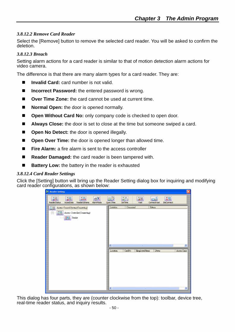
3.8.12.1 Configuring Card Reader Select a card reader in the System Setup tree and click [Reader] button in the toolbar. This will bring up the Reader Setting dialog as shown below:
1. Node: the serial number of this reader in current access controller.
2. Device Type: select a supported reader type from the dropdown list.
3. Location: Give a meaningful name for this card reader.
4. Click [Create] to save the setting and leave the dialog. Click [Apply] to save the setting and continue to setup other readers.
5. Click [Close] to give up the change and leave the dialog.
Chapter 3 The Admin Program
- 50 -
3.8.12.2 Remove Card Reader Select the [Remove] button to remove the selected card reader. You will be asked to confirm the deletion.
3.8.12.3 Breach Setting alarm actions for a card reader is similar to that of motion detection alarm actions for video camera.
The difference is that there are many alarm types for a card reader. They are:
Invalid Card: card number is not valid.
Incorrect Password: the entered password is wrong.
Over Time Zone: the card cannot be used at current time.
Normal Open: the door is opened normally.
Open Without Card No: only company code is checked to open door.
Always Close: the door is set to close at the time but someone swiped a card.
Open No Detect: the door is opened illegally.
Open Over Time: the door is opened longer than allowed time.
Fire Alarm: a fire alarm is sent to the access controller
Reader Damaged: the card reader is been tampered with.
Battery Low: the battery in the reader is exhausted
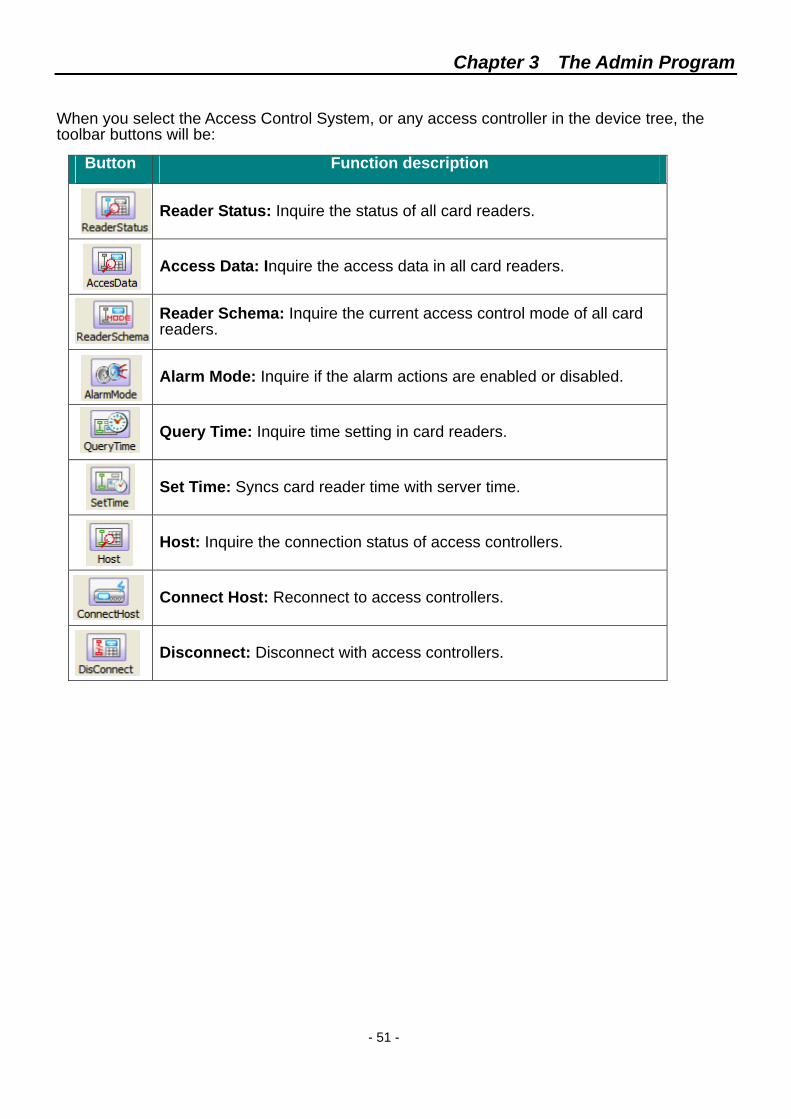
3.8.12.4 Card Reader Settings Click the [Setting] button will bring up the Reader Setting dialog box for inquiring and modifying card reader configurations, as shown below:
This dialog has four parts, they are (counter clockwise from the top): toolbar, device tree, real-time reader status, and inquiry results.
Chapter 3 The Admin Program
- 51 -
When you select the Access Control System, or any access controller in the device tree, the toolbar buttons will be:
Button Function description
Reader Status: Inquire the status of all card readers.
Access Data: Inquire the access data in all card readers.
Reader Schema: Inquire the current access control mode of all card readers.
Alarm Mode: Inquire if the alarm actions are enabled or disabled.
Query Time: Inquire time setting in card readers.
Set Time: Syncs card reader time with server time.
Host: Inquire the connection status of access controllers.
Connect Host: Reconnect to access controllers.
Disconnect: Disconnect with access controllers.
Chapter 3 The Admin Program
- 52 -
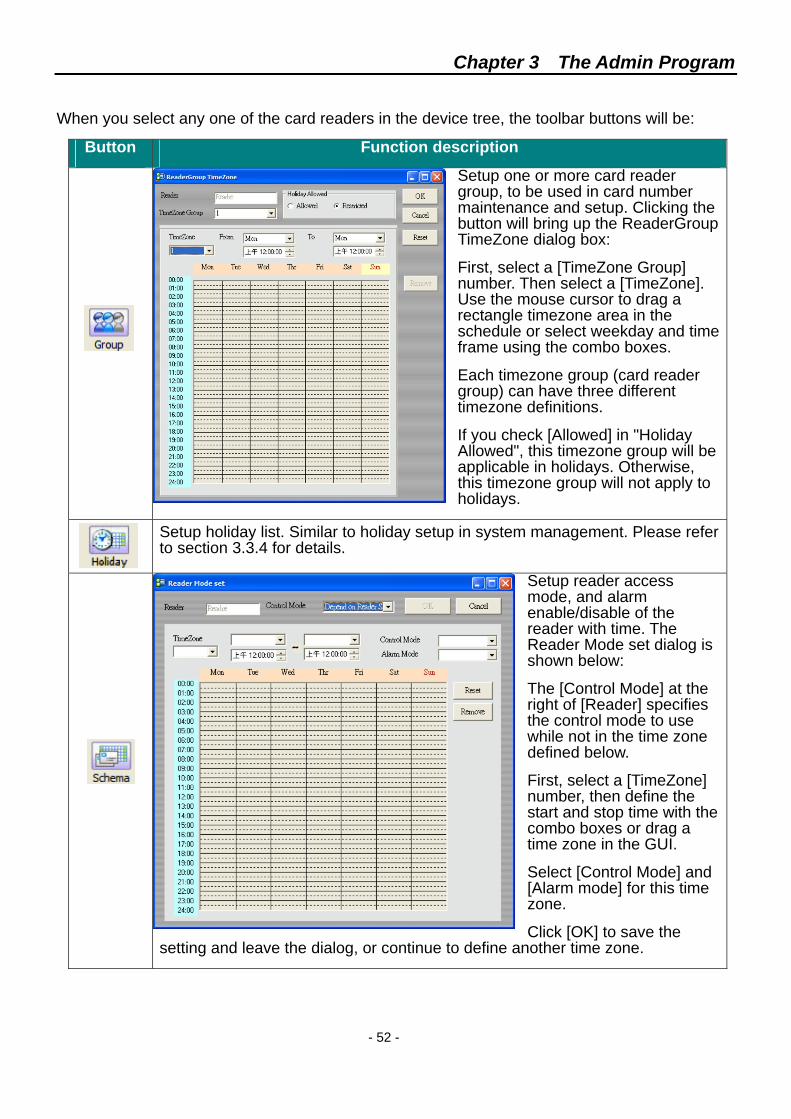
When you select any one of the card readers in the device tree, the toolbar buttons will be:
Button Function description
Setup one or more card reader group, to be used in card number maintenance and setup. Clicking the button will bring up the ReaderGroup TimeZone dialog box:
First, select a [TimeZone Group] number. Then select a [TimeZone]. Use the mouse cursor to drag a rectangle timezone area in the schedule or select weekday and time frame using the combo boxes.
Each timezone group (card reader group) can have three different timezone definitions.
If you check [Allowed] in "Holiday Allowed", this timezone group will be applicable in holidays. Otherwise, this timezone group will not apply to holidays.
Setup holiday list. Similar to holiday setup in system management. Please refer to section 3.3.4 for details.
Setup reader access mode, and alarm enable/disable of the reader with time. The Reader Mode set dialog is shown below:
The [Control Mode] at the right of [Reader] specifies the control mode to use while not in the time zone defined below.
First, select a [TimeZone] number, then define the start and stop time with the combo boxes or drag a time zone in the GUI.
Select [Control Mode] and [Alarm mode] for this time zone.
Click [OK] to save the setting and leave the dialog, or continue to define another time zone.
Chapter 3 The Admin Program
- 53 -
Click [Alarm Mode] to turn on or off card reader alarm.
Click [Door Lock] to set the door lock open time after a successful card swipe.
Click [Door Open] to set maximum allowed door open time. If door is kept opened longer than this time it will trigger an access alarm
After the card list in the card reader has been edited, use this function to reorganize the card list.
Check current door status.
Check to see if the card reader has access log.
Cancel current access alarm.
Open the door.
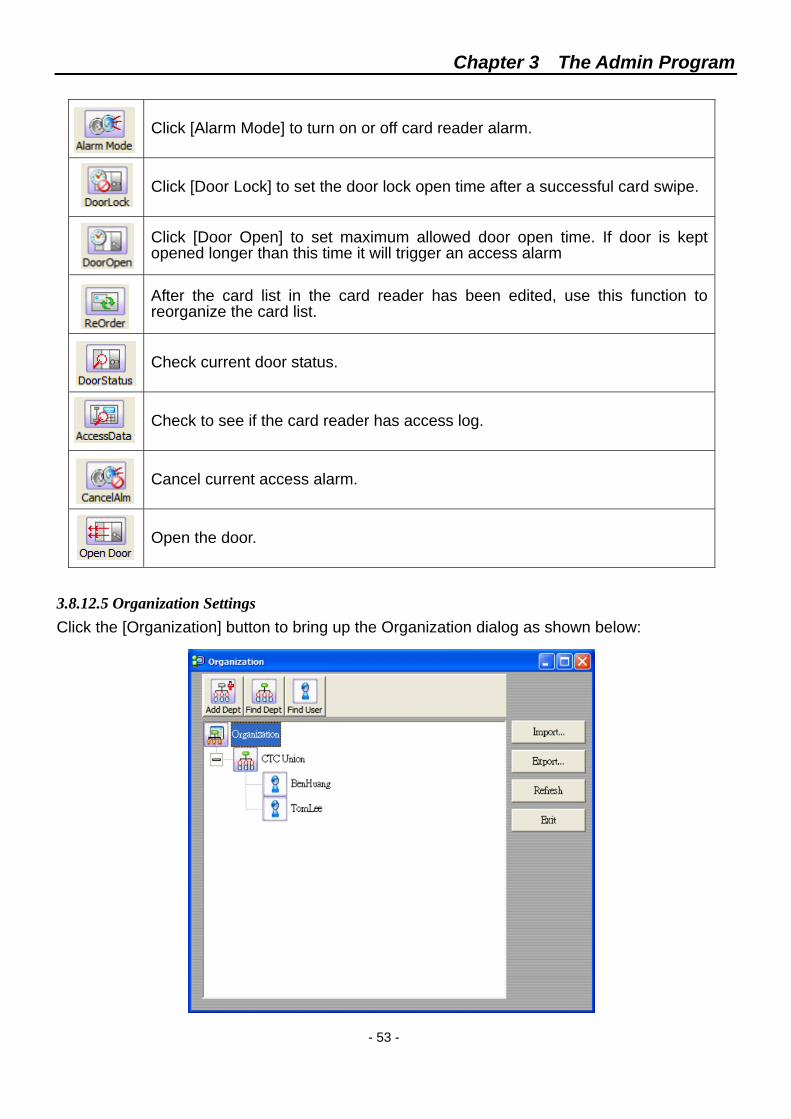
3.8.12.5 Organization Settings Click the [Organization] button to bring up the Organization dialog as shown below:
Chapter 3 The Admin Program
- 54 -
You must add department first, then you can add users to the department.
Remove all users in a department before remove the department.
Click to search for a department using department ID or name. The search strings are case sensitive. Click to search for a user using: Employee ID, Name, or card number. The search strings are case sensitive. Use [Import…] to import an organization file.
Use [Export…] to write current organization configuration into a file.
Use [Refresh] to redraw the organization chart.
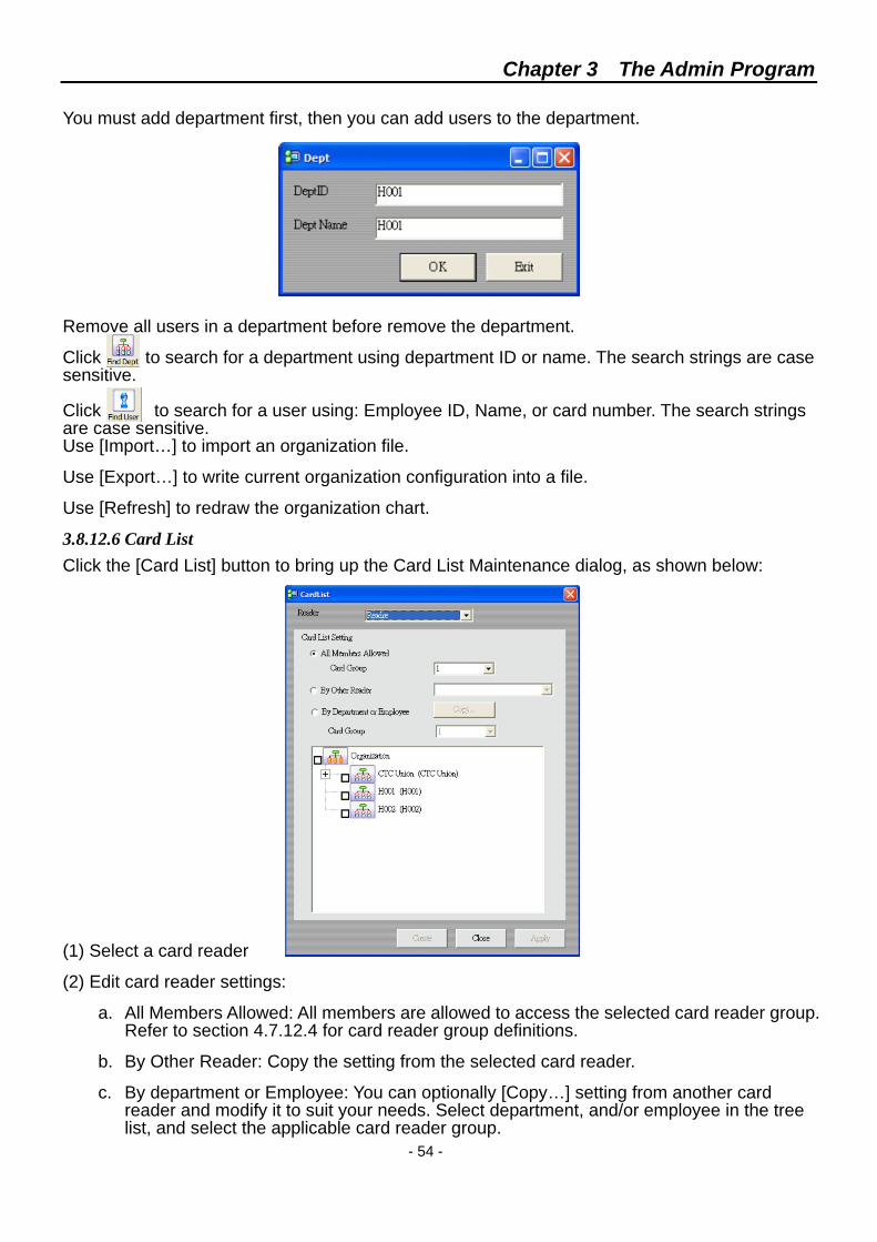
3.8.12.6 Card List Click the [Card List] button to bring up the Card List Maintenance dialog, as shown below:
(1) Select a card reader
(2) Edit card reader settings:
a. All Members Allowed: All members are allowed to access the selected card reader group. Refer to section 4.7.12.4 for card reader group definitions.
b. By Other Reader: Copy the setting from the selected card reader.
c. By department or Employee: You can optionally [Copy…] setting from another card reader and modify it to suit your needs. Select department, and/or employee in the tree list, and select the applicable card reader group.
Chapter 3 The Admin Program
- 55 -
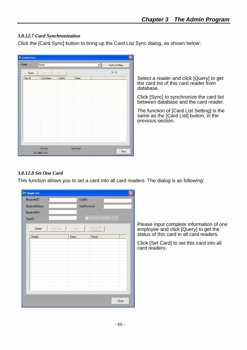
3.8.12.7 Card Synchronization Click the [Card Sync] button to bring up the Card List Sync dialog, as shown below:
Select a reader and click [Query] to get the card list of this card reader from database.
Click [Sync] to synchronize the card list between database and the card reader.
The function of [Card List Setting] is the same as the [Card List] button, in the previous section.
3.8.12.8 Set One Card This function allows you to set a card into all card readers. The dialog is as following:
Please input complete information of one employee and click [Query] to get the status of this card in all card readers.
Click [Set Card] to set this card into all card readers.
Chapter 3 The Admin Program
- 56 -
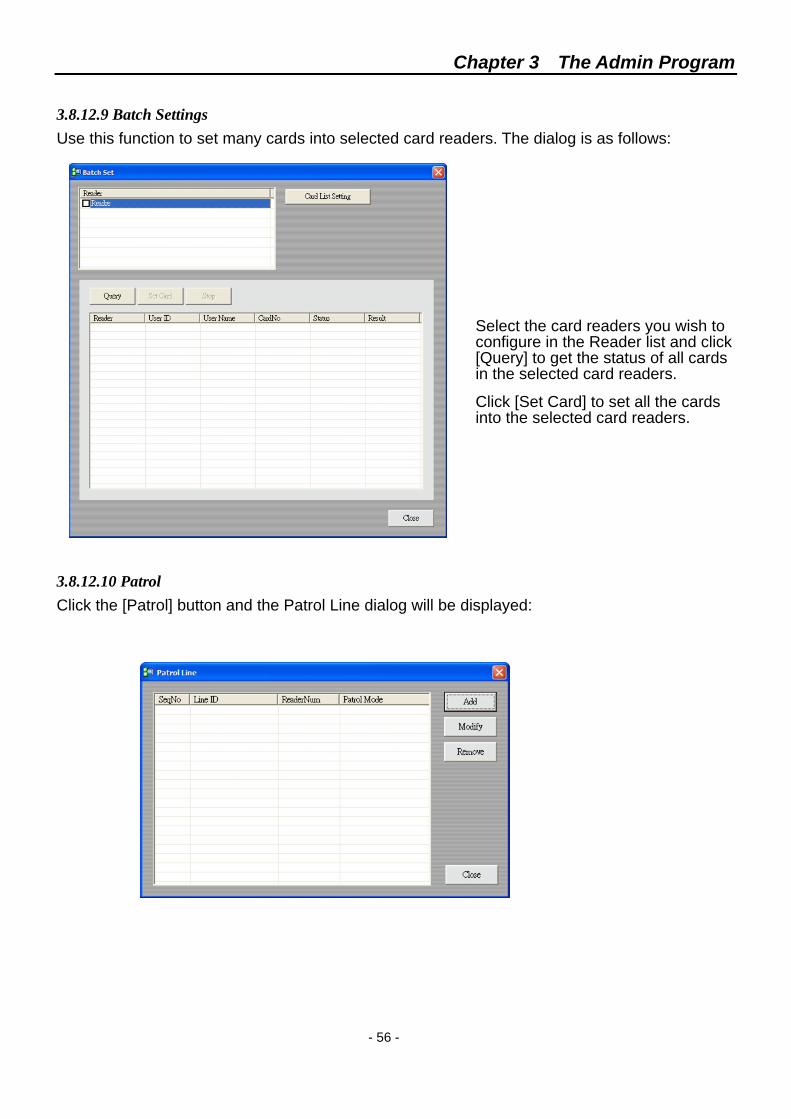
3.8.12.9 Batch Settings Use this function to set many cards into selected card readers. The dialog is as follows:
Select the card readers you wish to configure in the Reader list and click [Query] to get the status of all cards in the selected card readers.
Click [Set Card] to set all the cards into the selected card readers.
3.8.12.10 Patrol Click the [Patrol] button and the Patrol Line dialog will be displayed:
Chapter 3 The Admin Program
- 57 -
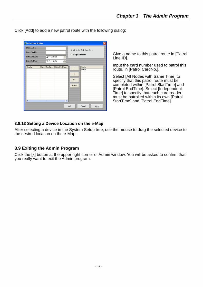
Click [Add] to add a new patrol route with the following dialog:
Give a name to this patrol route in [Patrol Line ID].
Input the card number used to patrol this route, in [Patrol CardNo.].
Select [All Nodes with Same Time] to specify that this patrol route must be completed within [Patrol StartTime] and [Patrol EndTime]. Select [Independent Time] to specify that each card reader must be patrolled within its own [Patrol StartTime] and [Patrol EndTime].
3.8.13 Setting a Device Location on the e-Map After selecting a device in the System Setup tree, use the mouse to drag the selected device to the desired location on the e-Map.
3.9 Exiting the Admin Program Click the [x] button at the upper right corner of Admin window. You will be asked to confirm that you really want to exit the Admin program.
Chapter 4 The Monitor Program
- 58 -
Chapter 4 The Monitor Program You can install the SmartView Plus Monitor program on many computers and use them simultaneously.
4.1 System Login The login procedure for Monitor program is the same as that of the admin program. Refer to section 3.1 for details.
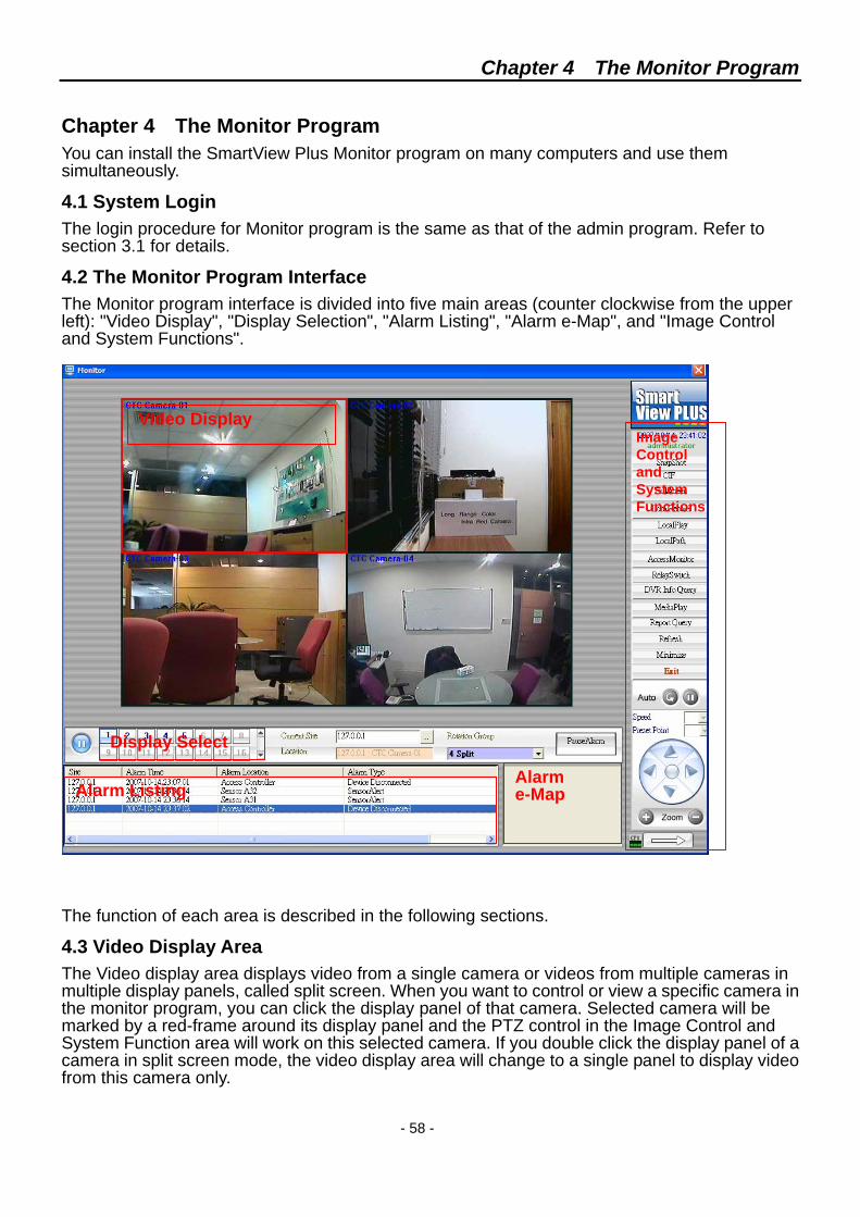
4.2 The Monitor Program Interface The Monitor program interface is divided into five main areas (counter clockwise from the upper left): "Video Display", "Display Selection", "Alarm Listing", "Alarm e-Map", and "Image Control and System Functions".
The function of each area is described in the following sections.
4.3 Video Display Area The Video display area displays video from a single camera or videos from multiple cameras in multiple display panels, called split screen. When you want to control or view a specific camera in the monitor program, you can click the display panel of that camera. Selected camera will be marked by a red-frame around its display panel and the PTZ control in the Image Control and System Function area will work on this selected camera. If you double click the display panel of a camera in split screen mode, the video display area will change to a single panel to display video from this camera only.
Video Display
Display Select
Alarm Listing Alarm e-Map
Image Control and System Functions
Chapter 4 The Monitor Program
- 59 -
4.4 Display Select toolbar
Video source select buttons. Selected video source will be displayed in a single panel occupying the whole Video Display area. Only video sources authorized to this user will be available.
When there are more than 16 video sources, use this button to switch to the other video source select buttons.
This is a list of available cameras to this user. The selected video source will be displayed in a single panel occupying the whole Video Display area.
This is the current split screen mode and a list of split screen modes available to this user. Select a mode from the list and the Video Display area will change accordingly.
This is a toggle button and will change between 'ResumeAlarm', 'PauseAlarm' and 'CancelAlarm'.
When there is an alarm, the button will display 'CancelAlarm' for you to cancel the current alarm.
Click on 'PauseAlarm' will stop the alarm notification on this monitor program while click on 'ResumeAlarm' will resume alarm notification.
Displays the current monitored site. Click […] to switch to other sites managed by the connected SVP server.
This is a toggle button and will change between 'Pause' and 'Play'. Click 'Pause' to pause the video and video rotation and click 'Play' to resume video and video rotation.
Note:
When you select a 36-panel split screen mode, the "Display Select", "Alarm Listing" and "Alarm e-Map" area will be hidden to accommodate that many display panels. Double click on any one panel to return to single panel display and bring back the "Display Select", "Alarm Listing" and "Alarm e-Map" areas.
Chapter 4 The Monitor Program
- 60 -
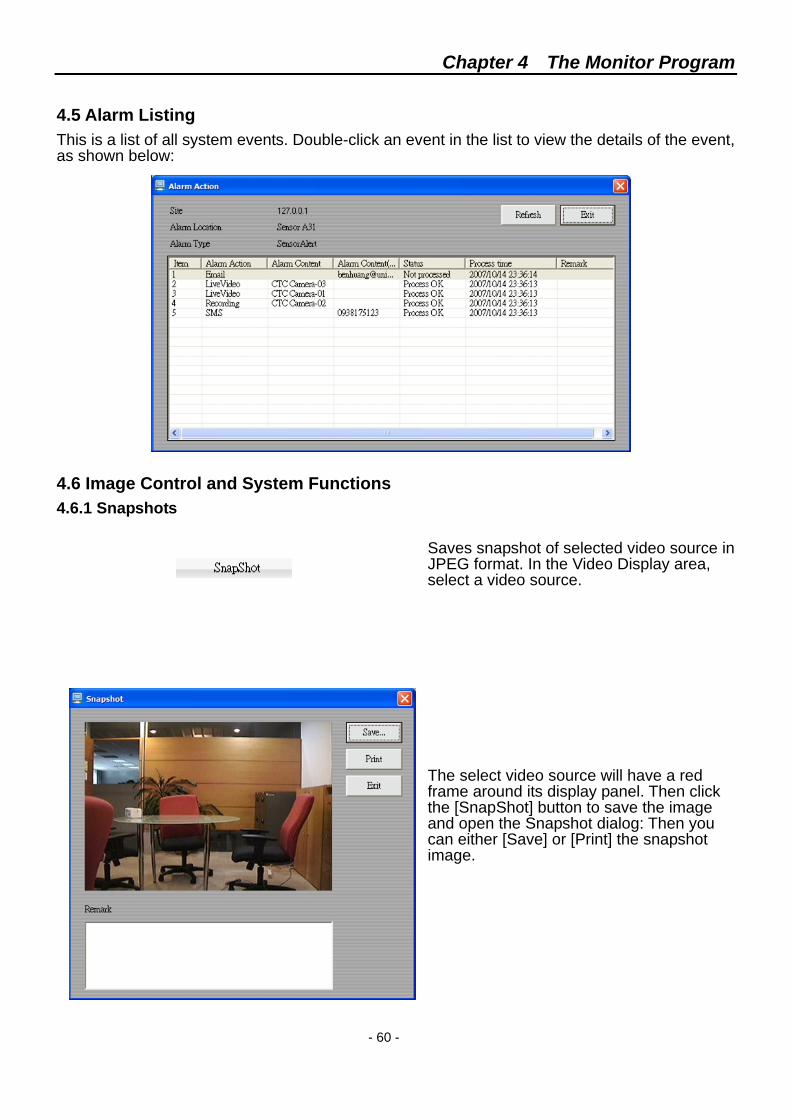
4.5 Alarm Listing This is a list of all system events. Double-click an event in the list to view the details of the event, as shown below:
4.6 Image Control and System Functions 4.6.1 Snapshots
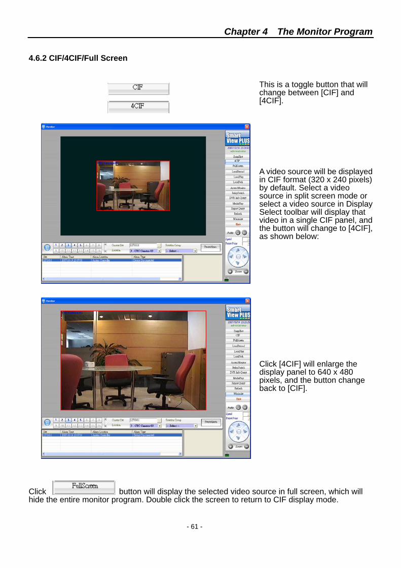
Saves snapshot of selected video source in JPEG format. In the Video Display area, select a video source.
The select video source will have a red frame around its display panel. Then click the [SnapShot] button to save the image and open the Snapshot dialog: Then you can either [Save] or [Print] the snapshot image.
Chapter 4 The Monitor Program
- 61 -
4.6.2 CIF/4CIF/Full Screen
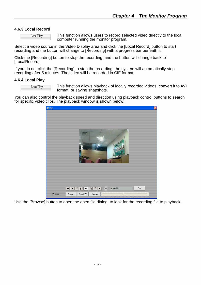
This is a toggle button that will change between [CIF] and [4CIF].
A video source will be displayed in CIF format (320 x 240 pixels) by default. Select a video source in split screen mode or select a video source in Display Select toolbar will display that video in a single CIF panel, and the button will change to [4CIF], as shown below:
Click [4CIF] will enlarge the display panel to 640 x 480 pixels, and the button change back to [CIF].
Click button will display the selected video source in full screen, which will hide the entire monitor program. Double click the screen to return to CIF display mode.
Chapter 4 The Monitor Program
- 62 -
4.6.3 Local Record
This function allows users to record selected video directly to the local computer running the monitor program.
Select a video source in the Video Display area and click the [Local Record] button to start recording and the button will change to [Recording] with a progress bar beneath it.
Click the [Recording] button to stop the recording, and the button will change back to [LocalRecord].
If you do not click the [Recording] to stop the recording, the system will automatically stop recording after 5 minutes. The video will be recorded in CIF format.
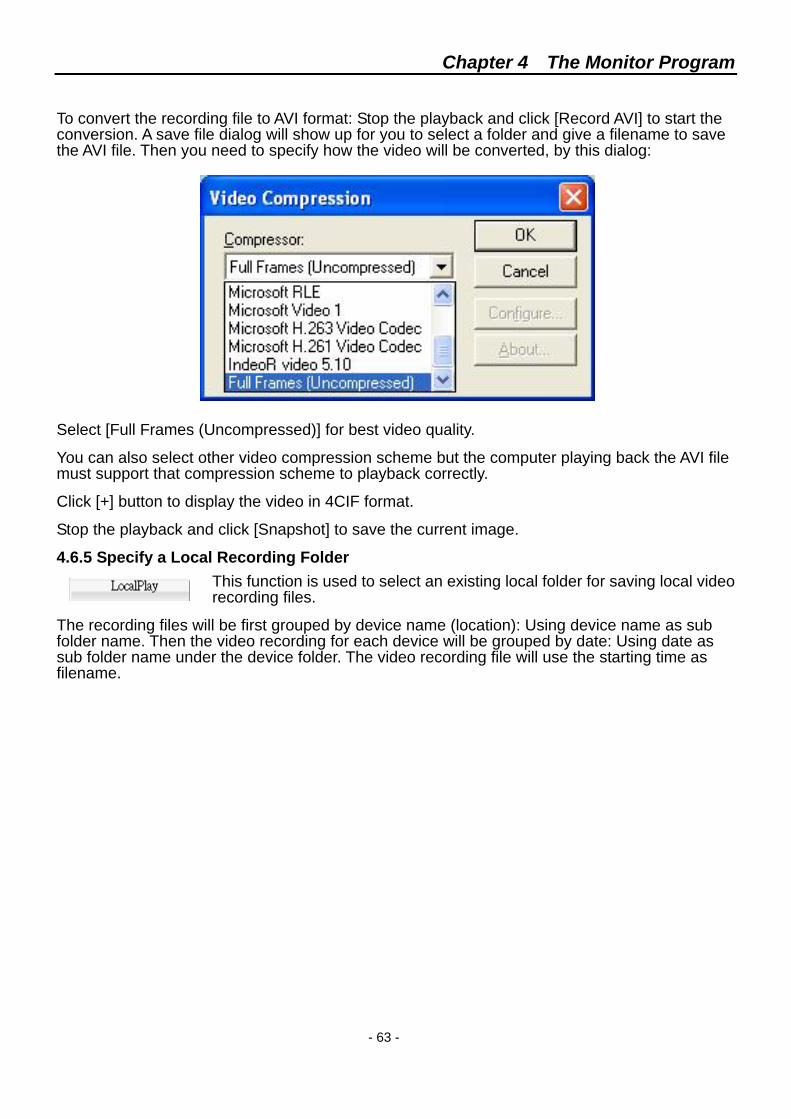
4.6.4 Local Play This function allows playback of locally recorded videos; convert it to AVI format, or saving snapshots.
You can also control the playback speed and direction using playback control buttons to search for specific video clips. The playback window is shown below:
Use the [Browse] button to open the open file dialog, to look for the recording file to playback.
Chapter 4 The Monitor Program
- 63 -
To convert the recording file to AVI format: Stop the playback and click [Record AVI] to start the conversion. A save file dialog will show up for you to select a folder and give a filename to save the AVI file. Then you need to specify how the video will be converted, by this dialog:
Select [Full Frames (Uncompressed)] for best video quality.
You can also select other video compression scheme but the computer playing back the AVI file must support that compression scheme to playback correctly.
Click [+] button to display the video in 4CIF format.
Stop the playback and click [Snapshot] to save the current image.
4.6.5 Specify a Local Recording Folder This function is used to select an existing local folder for saving local video recording files.
The recording files will be first grouped by device name (location): Using device name as sub folder name. Then the video recording for each device will be grouped by date: Using date as sub folder name under the device folder. The video recording file will use the starting time as filename.
Chapter 4 The Monitor Program
- 64 -
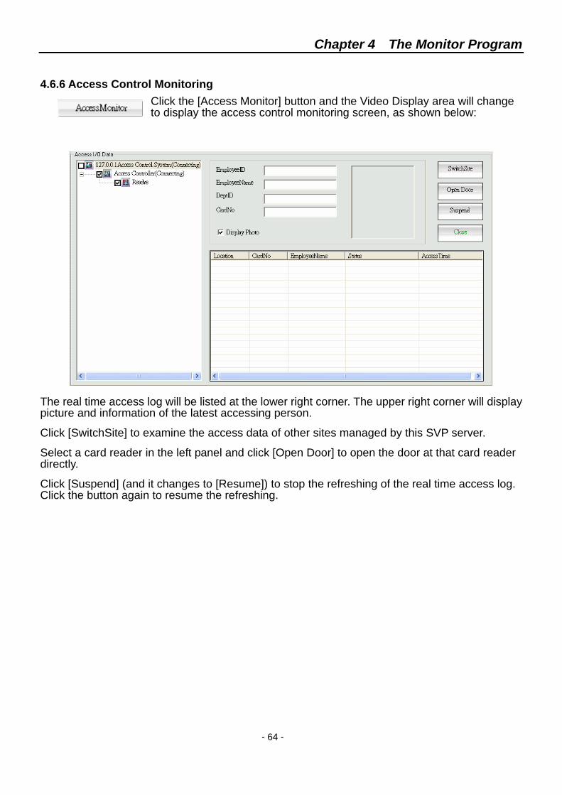
4.6.6 Access Control Monitoring Click the [Access Monitor] button and the Video Display area will change to display the access control monitoring screen, as shown below:
The real time access log will be listed at the lower right corner. The upper right corner will display picture and information of the latest accessing person.
Click [SwitchSite] to examine the access data of other sites managed by this SVP server.
Select a card reader in the left panel and click [Open Door] to open the door at that card reader directly.
Click [Suspend] (and it changes to [Resume]) to stop the refreshing of the real time access log. Click the button again to resume the refreshing.
Chapter 4 The Monitor Program
- 65 -
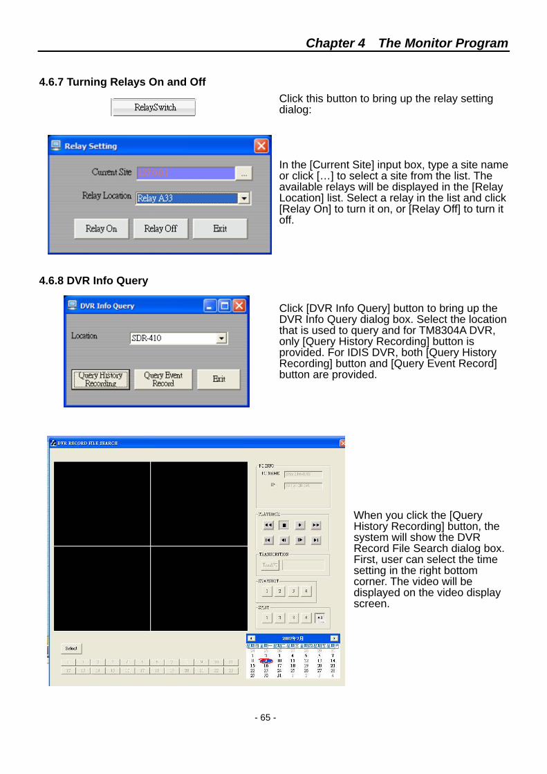
4.6.7 Turning Relays On and Off Click this button to bring up the relay setting dialog: In the [Current Site] input box, type a site name or click […] to select a site from the list. The available relays will be displayed in the [Relay Location] list. Select a relay in the list and click [Relay On] to turn it on, or [Relay Off] to turn it off.
4.6.8 DVR Info Query
Click [DVR Info Query] button to bring up the DVR Info Query dialog box. Select the location that is used to query and for TM8304A DVR, only [Query History Recording] button is provided. For IDIS DVR, both [Query History Recording] button and [Query Event Record] button are provided.
When you click the [Query History Recording] button, the system will show the DVR Record File Search dialog box. First, user can select the time setting in the right bottom corner. The video will be displayed on the video display screen.
Chapter 4 The Monitor Program
- 66 -
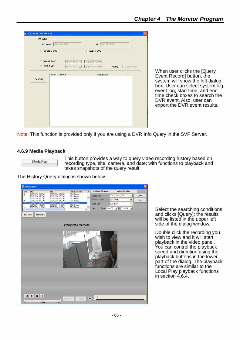
When user clicks the [Query Event Record] button, the system will show the left dialog box. User can select system log, event log, start time, and end time check boxes to search the DVR event. Also, user can export the DVR event results.
Note: This function is provided only if you are using a DVR Info Query in the SVP Server.
4.6.9 Media Playback This button provides a way to query video recording history based on recording type, site, camera, and date; with functions to playback and takes snapshots of the query result.
The History Query dialog is shown below:
Select the searching conditions and clicks [Query]; the results will be listed in the upper left side of the dialog window.
Double click the recording you wish to view and it will start playback in the video panel. You can control the playback speed and direction using the playback buttons in the lower part of the dialog. The playback functions are similar to the Local Play playback functions in section 4.6.4.
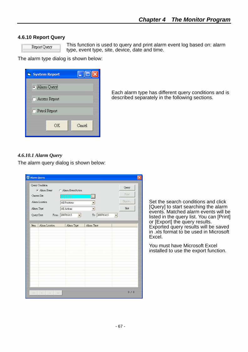
Chapter 4 The Monitor Program
- 67 -
4.6.10 Report Query This function is used to query and print alarm event log based on: alarm type, event type, site, device, date and time.
The alarm type dialog is shown below:
Each alarm type has different query conditions and is described separately in the following sections.
4.6.10.1 Alarm Query The alarm query dialog is shown below:
Set the search conditions and click [Query] to start searching the alarm events. Matched alarm events will be listed in the query list. You can [Print] or [Export] the query results. Exported query results will be saved in .xls format to be used in Microsoft Excel.
You must have Microsoft Excel installed to use the export function.
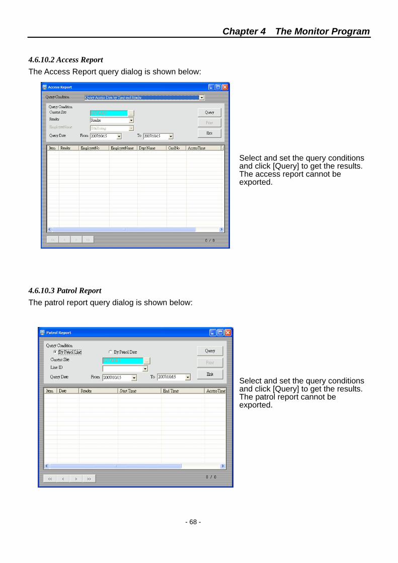
Chapter 4 The Monitor Program
- 68 -
4.6.10.2 Access Report The Access Report query dialog is shown below:
Select and set the query conditions and click [Query] to get the results. The access report cannot be exported.
4.6.10.3 Patrol Report The patrol report query dialog is shown below:
Select and set the query conditions and click [Query] to get the results. The patrol report cannot be exported.
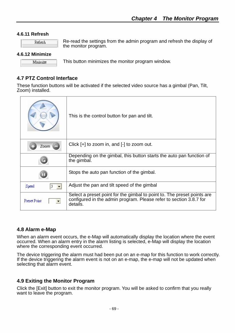
Chapter 4 The Monitor Program
- 69 -
4.6.11 Refresh
Re-read the settings from the admin program and refresh the display of the monitor program.
4.6.12 Minimize This button minimizes the monitor program window.
4.7 PTZ Control Interface These function buttons will be activated if the selected video source has a gimbal (Pan, Tilt, Zoom) installed.
This is the control button for pan and tilt.
Click [+] to zoom in, and [-] to zoom out.
Depending on the gimbal, this button starts the auto pan function of the gimbal.
Stops the auto pan function of the gimbal.
Adjust the pan and tilt speed of the gimbal
Select a preset point for the gimbal to point to. The preset points are configured in the admin program. Please refer to section 3.8.7 for details.
4.8 Alarm e-Map When an alarm event occurs, the e-Map will automatically display the location where the event occurred. When an alarm entry in the alarm listing is selected, e-Map will display the location where the corresponding event occurred.
The device triggering the alarm must had been put on an e-map for this function to work correctly. If the device triggering the alarm event is not on an e-map, the e-map will not be updated when selecting that alarm event.
4.9 Exiting the Monitor Program Click the [Exit] button to exit the monitor program. You will be asked to confirm that you really want to leave the program.
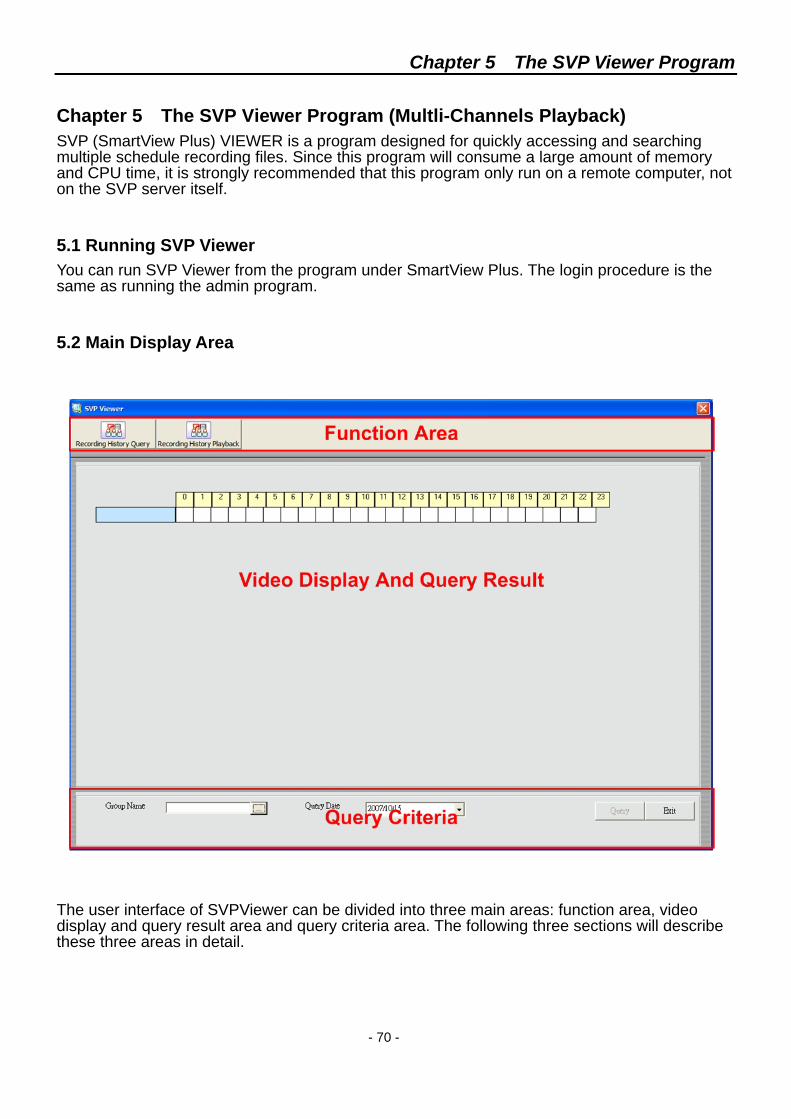
Chapter 5 The SVP Viewer Program
- 70 -
Chapter 5 The SVP Viewer Program (Multli-Channels Playback) SVP (SmartView Plus) VIEWER is a program designed for quickly accessing and searching multiple schedule recording files. Since this program will consume a large amount of memory and CPU time, it is strongly recommended that this program only run on a remote computer, not on the SVP server itself.
5.1 Running SVP Viewer You can run SVP Viewer from the program under SmartView Plus. The login procedure is the same as running the admin program.
5.2 Main Display Area The user interface of SVPViewer can be divided into three main areas: function area, video display and query result area and query criteria area. The following three sections will describe these three areas in detail.
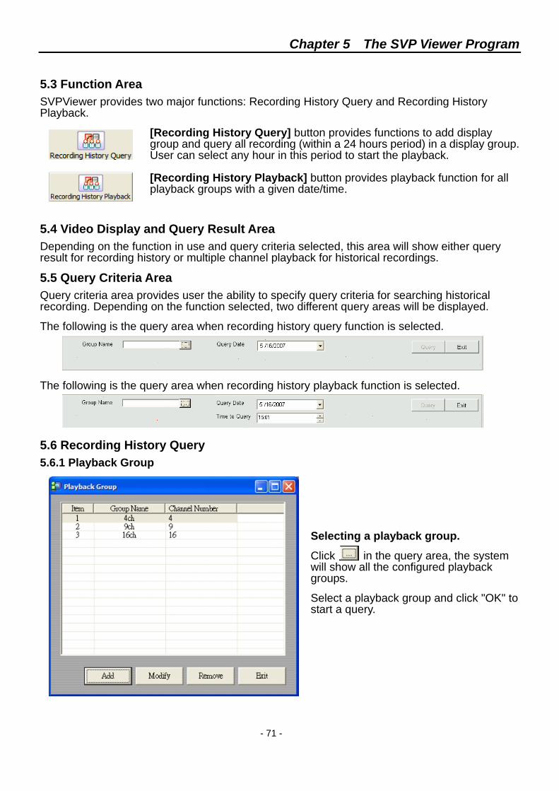
Chapter 5 The SVP Viewer Program
- 71 -
5.3 Function Area SVPViewer provides two major functions: Recording History Query and Recording History Playback.
[Recording History Query] button provides functions to add display group and query all recording (within a 24 hours period) in a display group. User can select any hour in this period to start the playback. [Recording History Playback] button provides playback function for all playback groups with a given date/time.
5.4 Video Display and Query Result Area Depending on the function in use and query criteria selected, this area will show either query result for recording history or multiple channel playback for historical recordings.
5.5 Query Criteria Area Query criteria area provides user the ability to specify query criteria for searching historical recording. Depending on the function selected, two different query areas will be displayed.
The following is the query area when recording history query function is selected.
The following is the query area when recording history playback function is selected.
5.6 Recording History Query 5.6.1 Playback Group
Selecting a playback group.
Click in the query area, the system will show all the configured playback groups.
Select a playback group and click "OK" to start a query.
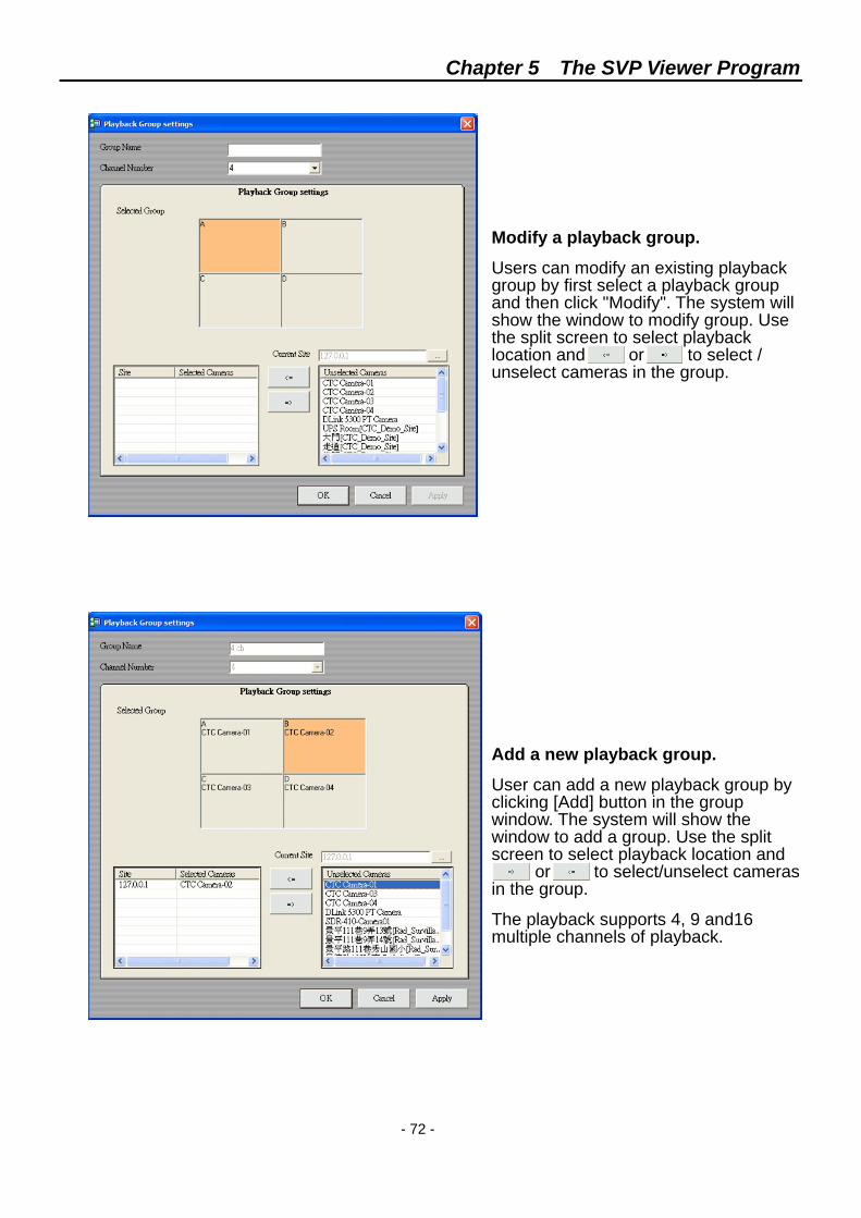
Chapter 5 The SVP Viewer Program
- 72 -
Modify a playback group.
Users can modify an existing playback group by first select a playback group and then click "Modify". The system will show the window to modify group. Use the split screen to select playback location and or to select / unselect cameras in the group.
Add a new playback group.
User can add a new playback group by clicking [Add] button in the group window. The system will show the window to add a group. Use the split screen to select playback location and or to select/unselect cameras in the group.
The playback supports 4, 9 and16 multiple channels of playback.
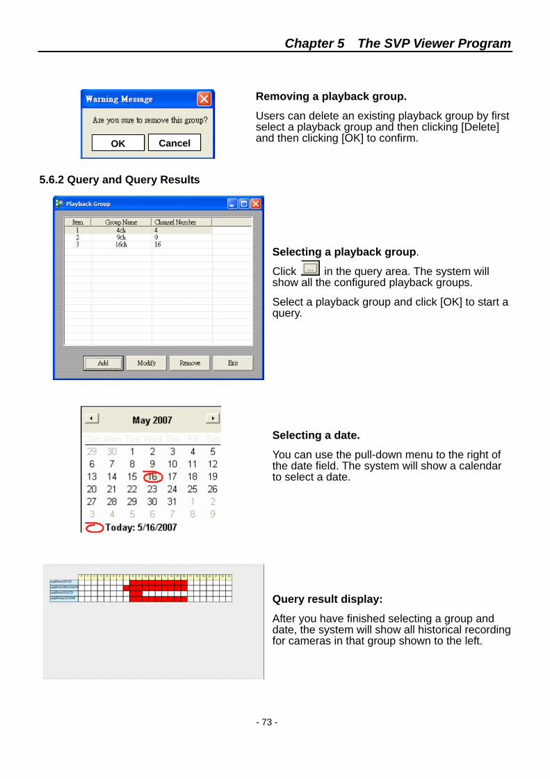
Chapter 5 The SVP Viewer Program
- 73 -
Removing a playback group.
Users can delete an existing playback group by first select a playback group and then clicking [Delete] and then clicking [OK] to confirm.
5.6.2 Query and Query Results
Selecting a playback group.
Click in the query area. The system will show all the configured playback groups.
Select a playback group and click [OK] to start a query.
Selecting a date.
You can use the pull-down menu to the right of the date field. The system will show a calendar to select a date.
Query result display:
After you have finished selecting a group and date, the system will show all historical recording for cameras in that group shown to the left.
OK Cancel
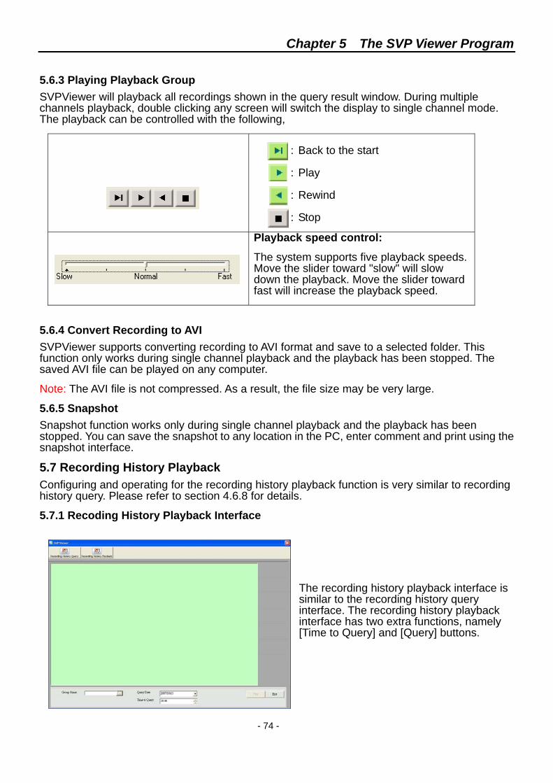
Chapter 5 The SVP Viewer Program
- 74 -
5.6.3 Playing Playback Group SVPViewer will playback all recordings shown in the query result window. During multiple channels playback, double clicking any screen will switch the display to single channel mode. The playback can be controlled with the following,
: Back to the start : Play : Rewind : Stop
Playback speed control:
The system supports five playback speeds. Move the slider toward "slow" will slow down the playback. Move the slider toward fast will increase the playback speed.
5.6.4 Convert Recording to AVI SVPViewer supports converting recording to AVI format and save to a selected folder. This function only works during single channel playback and the playback has been stopped. The saved AVI file can be played on any computer.
Note: The AVI file is not compressed. As a result, the file size may be very large.
5.6.5 Snapshot Snapshot function works only during single channel playback and the playback has been stopped. You can save the snapshot to any location in the PC, enter comment and print using the snapshot interface.
5.7 Recording History Playback Configuring and operating for the recording history playback function is very similar to recording history query. Please refer to section 4.6.8 for details.
5.7.1 Recoding History Playback Interface
The recording history playback interface is similar to the recording history query interface. The recording history playback interface has two extra functions, namely [Time to Query] and [Query] buttons.
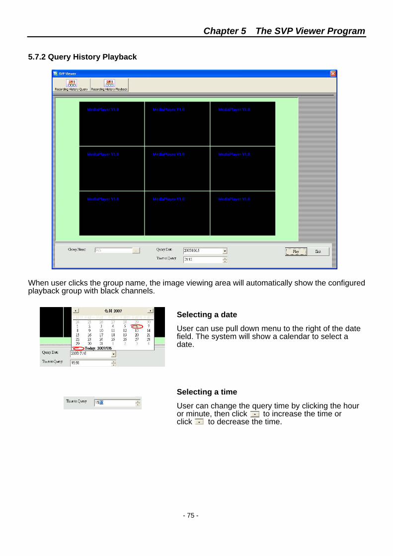
Chapter 5 The SVP Viewer Program
- 75 -
5.7.2 Query History Playback When user clicks the group name, the image viewing area will automatically show the configured playback group with black channels.
Selecting a date
User can use pull down menu to the right of the date field. The system will show a calendar to select a date.
Selecting a time
User can change the query time by clicking the hour or minute, then click to increase the time or click to decrease the time.
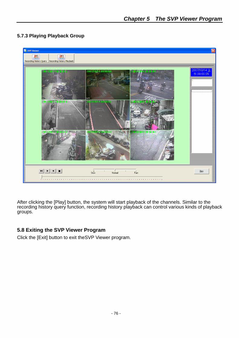
Chapter 5 The SVP Viewer Program
- 76 -
5.7.3 Playing Playback Group After clicking the [Play] button, the system will start playback of the channels. Similar to the recording history query function, recording history playback can control various kinds of playback groups.
5.8 Exiting the SVP Viewer Program Click the [Exit] button to exit theSVP Viewer program.


DVS Series CTC Union Technologies Co., Ltd. Far Eastern Vienna Technology Center (Neihu Technology Park) 8F, No.60, Zhouzi Street Neihu District, Taipei, Taiwan Phone:(886) 2.2659.1021 Fax:(886) 2.2799.1355
E-mail: [email protected] Url:http://www.ctcu.com