sme2713 casting 02
DESCRIPTION
casting methods chapter 2TRANSCRIPT
1
CASTING PROCESS - 2
Assoc Prof Zainal Abidin AhmadUniversiti Teknologi Malaysia
31-Jan-08 Assoc Prof Zainal Abidin Ahmad 2
Outline• Casting Molds
– Gating system – pouring basin, sprue, runner, gate– Riser– Core
• Heating and melting– Melting furnaces
• Pouring• Solidification• Additional processes after solidification• Metals for casting
31-Jan-08 Assoc Prof Zainal Abidin Ahmad 3
The Mold in Casting
• Contains cavity whose geometry determines part shape – Actual size and shape of cavity must be slightly
oversized to allow for shrinkage of metal during solidification and cooling, draf allowance and machining allowance
– Molds are made of a variety of materials, including sand, plaster, ceramic, and metal
31-Jan-08 Assoc Prof Zainal Abidin Ahmad 4
Sand Casting Mold Terms
• Mold consists of two halves: – Cope = upper half of mold– Drag = bottom half
• Mold halves are contained in a box, called a flask
• The two halves separate at the parting line

2
31-Jan-08 Assoc Prof Zainal Abidin Ahmad 5
The Mold
31-Jan-08 Assoc Prof Zainal Abidin Ahmad 6
Sand casting mold
31-Jan-08 Assoc Prof Zainal Abidin Ahmad 7 31-Jan-08 Assoc Prof Zainal Abidin Ahmad 8

3
31-Jan-08 Assoc Prof Zainal Abidin Ahmad 9 31-Jan-08 Assoc Prof Zainal Abidin Ahmad 10
Finish casting
31-Jan-08 Assoc Prof Zainal Abidin Ahmad 11
Forming the Mold Cavity
• Mold cavity is formed by packing sand around a pattern, which has the shape of the part
• When the pattern is removed, the remaining cavity has desired shape of cast part
• The pattern is usually oversized to allow for shrinkage of metal as it solidifies and cools
• Sand for the mold is moist and contains a binder to maintain shape
• Video clips
31-Jan-08 Assoc Prof Zainal Abidin Ahmad 12
Gating System
• Channel through which molten metal flows into cavity from outside of mold
• Consists of a downsprue, through which metal enters a runner leading to the main cavity
• At top of downsprue, a pouring cup is often used to minimize splash and turbulence as the metal flows into downsprue

4
31-Jan-08 Assoc Prof Zainal Abidin Ahmad 13
Riser
• Reservoir in the mold which is a source of liquid metal to compensate for shrinkage during solidification
• The riser must be designed to freeze after the main casting in order to satisfy its function
31-Jan-08 Assoc Prof Zainal Abidin Ahmad 14
Riser Design
• Riser is waste metal that is separated from the casting and remelted to make more castings
• To minimize waste in the unit operation, it is desirable for the volume of metal in the riser to be a minimum
31-Jan-08 Assoc Prof Zainal Abidin Ahmad 15 31-Jan-08 Assoc Prof Zainal Abidin Ahmad 16
Cores in the Mold Cavity
• The mold cavity provides the external surfaces of the cast part
• In addition, a casting may have internal surfaces, determined by a core, placed inside the mold cavity to define the interior geometry of part
• In sand casting, cores are generally made of sand

5
31-Jan-08 Assoc Prof Zainal Abidin Ahmad 17 31-Jan-08 Assoc Prof Zainal Abidin Ahmad 18
Heating the Metal
• Heating furnaces are used to heat the metal to molten temperature sufficient for casting
• The heat required is the sum of: 1. Heat to raise temperature to melting point 2. Heat of fusion to convert from solid to liquid 3. Heat to raise molten metal to desired temperature for
pouring
31-Jan-08 Assoc Prof Zainal Abidin Ahmad 19
Melting furnaces - Cupola
31-Jan-08 Assoc Prof Zainal Abidin Ahmad 20
Melting furnaces - Cupola
• Vertical cylindrical furnace equipped with tapping spout near base
• Used only for cast irons, although other furnaces are also used, largest tonnage of cast iron in melted in cupolas.
• The “CHARGE”, consisting of iron, coke, flux, and alloying elements, is loaded through a charging door located less than halfway up height of cupola.

6
31-Jan-08 Assoc Prof Zainal Abidin Ahmad 21
Melting furnaces - Crucible
• Metal is melted without direct contact with burning fuel mixture
• Sometimes called indirect fuel-fired furnace• Container (crucible) is made of refractory
material or high-temperature steel alloy• Used for non-ferrous metals such as
bronze, brass, and alloys of zinc and aluminium.
• Three types used in foundries
31-Jan-08 Assoc Prof Zainal Abidin Ahmad 22
Melting furnaces - Crucible
31-Jan-08 Assoc Prof Zainal Abidin Ahmad 23
Melting furnaces –Direct fuel fired
• Small open-hearth in which charge is heated by natural gas fuel burners located on side of furnace.
• Furnace roof assists heating action by reflecting flame down against charge
• At bottom of hearth is a tap hole to release molten metal.
• Generally used for nonferrous metals such as copper based alloys and aluminium.
31-Jan-08 Assoc Prof Zainal Abidin Ahmad 24
Melting furnaces
7
31-Jan-08 Assoc Prof Zainal Abidin Ahmad 25
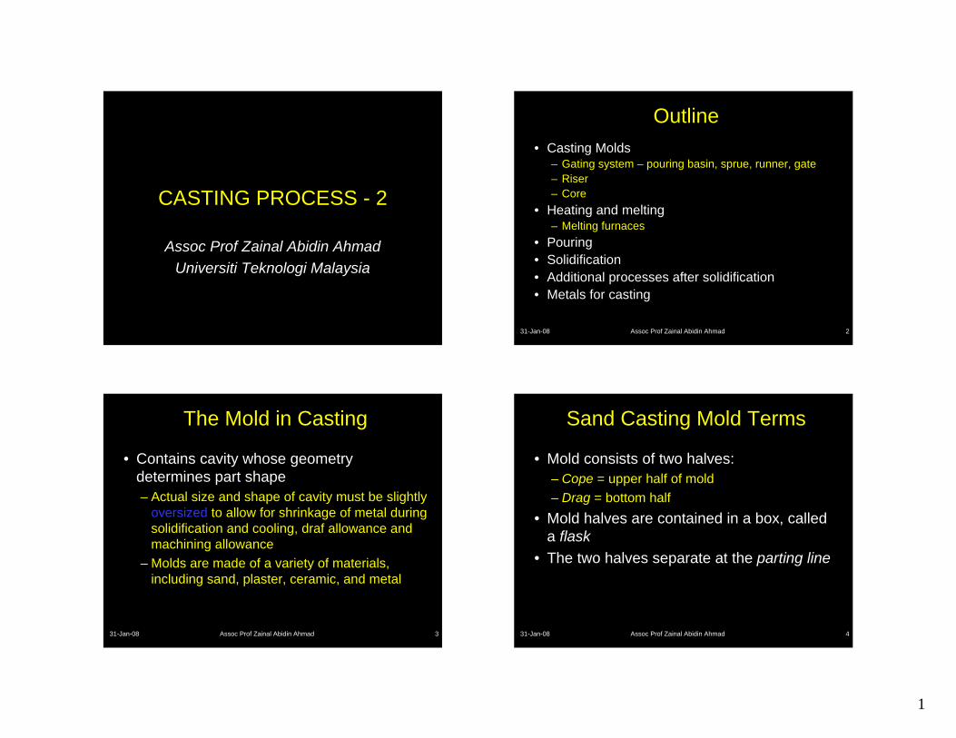
Melting furnaces – electric arc
• Charge is melted by heat generated from an electric arc
• High power consumption, but electric arc furnaces can be designed for high melting capacity
• Used primarily for melting steel
31-Jan-08 Assoc Prof Zainal Abidin Ahmad 26
Melting furnaces – electric arc
31-Jan-08 Assoc Prof Zainal Abidin Ahmad 27
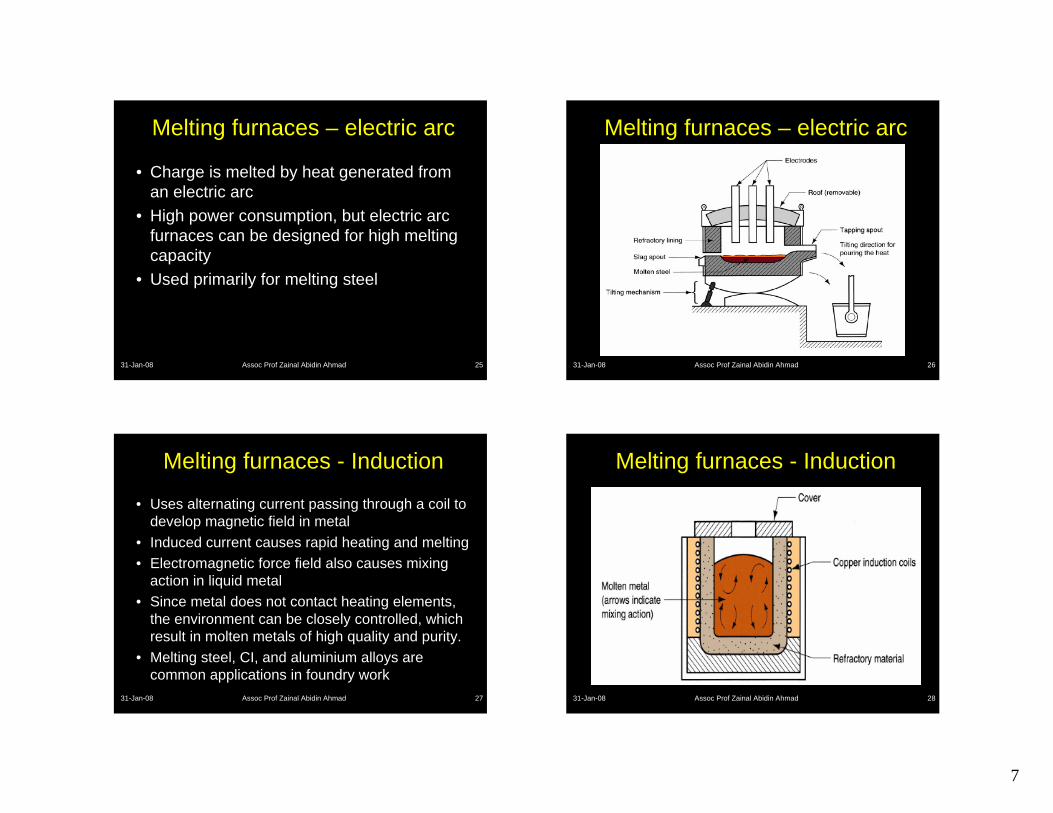
Melting furnaces - Induction
• Uses alternating current passing through a coil to develop magnetic field in metal
• Induced current causes rapid heating and melting• Electromagnetic force field also causes mixing
action in liquid metal• Since metal does not contact heating elements,
the environment can be closely controlled, which result in molten metals of high quality and purity.
• Melting steel, CI, and aluminium alloys are common applications in foundry work
31-Jan-08 Assoc Prof Zainal Abidin Ahmad 28
Melting furnaces - Induction

8
31-Jan-08 Assoc Prof Zainal Abidin Ahmad 29
Melting furnaces
31-Jan-08 Assoc Prof Zainal Abidin Ahmad 30
Melting furnaces
31-Jan-08 Assoc Prof Zainal Abidin Ahmad 31
Pouring the Molten Metal
• For this step to be successful, metal must flow into all regions of the mold, most importantly the main cavity, before solidifying
• Factors that determine success:– Pouring temperature– Pouring rate– Turbulence
31-Jan-08 Assoc Prof Zainal Abidin Ahmad 32
Ladles• Used to move molten metal from furnace to
mold

9
31-Jan-08 Assoc Prof Zainal Abidin Ahmad 33
Solidification of MetalsTransformation of molten metal back into solid state• Solidification differs depending on whether the
metal is a pure element or an alloy
Figure 10.4 - Cooling curve for a pure metal during casting
31-Jan-08 Assoc Prof Zainal Abidin Ahmad 34
Solidification of Pure Metals
• Due to chilling action of mold wall, a thin skin of solid metal is formed at the interface immediately after pouring
• Skin thickness increases to form a shell around the molten metal as solidification progresses
• Rate of freezing depends on heat transfer into mold, as well as thermal properties of the metal
31-Jan-08 Assoc Prof Zainal Abidin Ahmad 35
Figure 10.5 - Characteristic grain structure in a casting of a pure metal, showing randomly oriented grains of small size near the mold wall, and large columnar grains oriented toward the center of the casting
31-Jan-08 Assoc Prof Zainal Abidin Ahmad 36
Figure 10.6 - (a) Phase diagram for a copper-nickel alloy system and (b) associated cooling curve for a
50%Ni-50%Cu composition during casting
Most alloys freeze over a temperature range rather than at a single temperature

10
31-Jan-08 Assoc Prof Zainal Abidin Ahmad 37
Figure 10.7 - Characteristic grain structure in an alloy casting, showing segregation of alloying components
in center of casting
31-Jan-08 Assoc Prof Zainal Abidin Ahmad 38
Solidification Time
• Solidification takes time• Total solidification time TST = time required for
casting to solidify after pouring• TST depends on size and shape of casting by
relationship known as Chvorinov's Rule
31-Jan-08 Assoc Prof Zainal Abidin Ahmad 39
Chvorinov's Rule
where TST = total solidification time; V = volume of the casting; A = surface area of casting; n = exponent usually taken to have a value = 2; and Cm is mold constant
n
m AVCTST ⎟⎠⎞
⎜⎝⎛=
31-Jan-08 Assoc Prof Zainal Abidin Ahmad 40
Mold Constant in Chvorinov's Rule
• Cm depends on mold material, thermal properties of casting metal, and pouring temperature relative to melting point
• Value of Cm for a given casting operation can be based on experimental data from previous operations carried out using same mold material, metal, and pouring temperature, even though the shape of the part may be quite different

11
31-Jan-08 Assoc Prof Zainal Abidin Ahmad 41
What Chvorinov's Rule Tells Us
• A casting with a higher volume-to-surface area ratio cools and solidifies more slowly than one with a lower ratio– To feed molten metal to main cavity, TST for riser must greater
than TST for main casting
• Since riser and casting mold constants will be equal, design the riser to have a larger volume-to-area ratio so that the main casting solidifies first – This minimizes the effects of shrinkage
31-Jan-08 Assoc Prof Zainal Abidin Ahmad 42
Figure 10.8 - Shrinkage of a cylindrical casting during solidification and cooling: (0) starting level of molten metal immediately after pouring; (1) reduction in level caused by liquid contraction during cooling (dimensional reductions are exaggerated for clarity in sketches)
31-Jan-08 Assoc Prof Zainal Abidin Ahmad 43
Figure 10.8 - (2) reduction in height and formation of shrinkage cavity caused by solidification shrinkage; (3) further reduction in height and diameter due to thermal contraction during cooling of the solid metal (dimensional reductions are exaggerated for clarity in our sketches)
31-Jan-08 Assoc Prof Zainal Abidin Ahmad 44
Solidification Shrinkage
• Occurs in nearly all metals because the solid phase has a higher density than the liquid phase
• Thus, solidification causes a reduction in volume per unit weight of metal
• Exception: cast iron with high C content – Graphitization during final stages of freezing causes
expansion that counteracts volumetric decrease associated with phase change

12
31-Jan-08 Assoc Prof Zainal Abidin Ahmad 45
Shrinkage Allowance
• Patternmakers account for solidification shrinkage and thermal contraction by making mold cavity oversized
• Amount by which mold is made larger relative to final casting size is called pattern shrinkage allowance
• Casting dimensions are expressed linearly, so allowances are applied accordingly
31-Jan-08 Assoc Prof Zainal Abidin Ahmad 46
Directional Solidification
• To minimize damaging effects of shrinkage, it is desirable for regions of the casting most distant from the liquid metal supply to freeze first and for solidification to progress from these remote regions toward the riser(s)– Thus, molten metal is continually available from risers
to prevent shrinkage voids – The term directional solidification describes this aspect
of freezing and methods by which it is controlled
31-Jan-08 Assoc Prof Zainal Abidin Ahmad 47
Achieving Directional Solidification
• Desired directional solidification is achieved using Chvorinov's Rule to design the casting itself, its orientation in the mold, and the riser system that feeds it
• Locate sections of the casting with lower V/A ratios away from riser, so freezing occurs first in these regions, and the liquid metal supply for the rest of the casting remains open
• Chills - internal or external heat sinks that cause rapid freezing in certain regions of the casting
31-Jan-08 Assoc Prof Zainal Abidin Ahmad 48
Figure 10.9 - (a) External chill to encourage rapid freezing of the molten metal in a thin section of the
casting; and (b) the likely result if the external chill were not used

13
31-Jan-08 Assoc Prof Zainal Abidin Ahmad 49
Additional steps after solidification
• Trimming• Removing the core• Surface cleaning• Inspection• Repair, if required• Heat treatment
31-Jan-08 Assoc Prof Zainal Abidin Ahmad 50
Trimming
• Removal of sprues, runners, risers, parting-line flash, fins, chaplets and any other excess metal from the cast part
• Can be done by hammering, shearing, hack-sawing, band-sawing, abrasive wheel cutting or torch cutting methods.
31-Jan-08 Assoc Prof Zainal Abidin Ahmad 51
Removing cores
• If cores have been used, they must be removed.
• Most cores are bonded, and they often fall out of casting as the binder deteriorates.
• In some cases, they are removed by shaking casting – manually or mechanically.
• Solid cores must be hammered or pressed out.
31-Jan-08 Assoc Prof Zainal Abidin Ahmad 52
Surface cleaning
• Removal of sand from casting surface and otherwise enhancing appearance of surface.
• Various cleaning methods : tubmling, air-blasting with coarse sand or metal shot, wire brushing, buffing and chemical pickling.
• Surface cleaning is most important for sand casting, this step can be avoided for most permanent molds.

14
31-Jan-08 Assoc Prof Zainal Abidin Ahmad 53
Heat treatment
• Castings are often heat treated to enhance properties
• Reasons for heat treating– For subsequence processing operations such
as machining– To bring out the desired properties for
application of the part in service.
31-Jan-08 Assoc Prof Zainal Abidin Ahmad 54
Metals for Casting
• Most commercial castings are made of alloys rather than pure metals – Alloys are generally easier to cast, and properties of
product are better • Casting alloys can be classified as:
– Ferrous – Nonferrous
31-Jan-08 Assoc Prof Zainal Abidin Ahmad 55
Ferrous Casting Alloys: Cast Iron
• Most important of all casting alloys • Tonnage of cast iron castings is several times
that of all other metals combined • Several types: (1) gray cast iron, (2) nodular iron,
(3) white cast iron, (4) malleable iron, and (5) alloy cast irons
• Typical pouring temperatures ∼ 1400°C (2500°F), depending on composition
31-Jan-08 Assoc Prof Zainal Abidin Ahmad 56
Ferrous Casting Alloys: Steel
• The mechanical properties of steel make it an attractive engineering material
• The capability to create complex geometries makes casting an attractive shaping process
• Difficulties faced by the foundry working with steel:– Pouring temperature of steel is higher than for most
other casting metals ∼ 1650°C (3000°F) – At these temperatures, steel readily oxidizes, so
molten metal must be isolated from air – Molten steel has relatively poor fluidity

15
31-Jan-08 Assoc Prof Zainal Abidin Ahmad 57
Nonferrous Casting Alloys: Aluminum
• Generally considered to be very castable• Pouring temperatures low – melting temperature
of aluminum Tm = 660°C (1220°F) • Properties:
– Light weight– Range of strength properties by heat treatment– Ease of machining
31-Jan-08 Assoc Prof Zainal Abidin Ahmad 58
Nonferrous Casting Alloys: Copper Alloys
• Includes bronze, brass, and aluminum bronze • Properties:
– Corrosion resistance– Attractive appearance – Good bearing qualities
• Limitation: high cost of copper • Applications: pipe fittings, marine propeller
blades, pump components, ornamental jewelry
31-Jan-08 Assoc Prof Zainal Abidin Ahmad 59
Nonferrous Casting Alloys: Zinc Alloys
• Highly castable, commonly used in die casting • Low melting point – melting point of zinc Tm =
419°C (786°F)• Good fluidity for ease of casting• Properties:
– Low creep strength, so castings cannot be subjected to prolonged high stresses