smoke control - pdfs.semanticscholar.org€¦ · i 4-232design calculations effect flows. when the...
TRANSCRIPT

section 4/Chapter 12----------–IN: Di.Nenno, P.J., et al., Editors, SFPE Handbook of Fire Protection Engineering,2nd Edition, Chapter 12, Section 4, 4/230-245
SMOKE CONTROLJohn H. Klote
INTRODUCTION
In building fire situations, smoke often flows toloca-tionsremote from the fire, threatening life and damagingproperty. Stairwells and elevators frequently becomesmoke-logged, thereby blocking ancI/orandinhibiting evac-uation. Today smokeisrecognized as themajorkiller infiresituations,l
In the late 1960s, the idea of using pressurization toprevent smoke infiltration of stairwells started to attract at-tention. This was followed by the idea of the “pressure sand-wich,” i.e., venting or exhausting the fire floor and pressur-izing the surrounding floors. Frequently, the building’sventilation system is used for this purpose. The term “smokecontrol” was coined as a name for such systems that usepressurization produced by mechanical fans to limit smokemovement in fire situations.
Research in the field of smoke control has been con-ducted in Australia, Canada, England, France, Japan, theUnited States, and West Germany. This research has con-sisted of field tests, full-scale fire tests, and computer simu-lations. Many buildings have been built with smoke controlsystems and numerous others have been retrofitted forsmoke control.
In this chapter the term smoke is defined in accordancewith the American Society for Testing and Materials(ASTM)2 and the National Fire Protection Association(NFPA)3 definitions which state that smoke consists of theairborne solid and liquid particulate and gases evolvedwhen a material undergoes pyrolysis of combustion.
SMOKE MOVEMENT
A smoke control system must be designed so that it isnot overpowered by the driving forces that cause smokemovement. For this reason, an understanding of the funda-mental concepts of smoke movement and of smoke control isa prerequisite to intelligent smoke control design. The majordriving forces causing smoke movement are stack effect,buoyancy, expansion, wind, and the heating, ventilating,and air conditioning [I-WAC) system. Generally, in a fire
Dr. John H. Klote is Leaderof SmokeManagementResearchat theBuildingand Fire Research Laboratoryof the NationalInstitute ofStandardsand Technology.
4-230
situation, smoke movement will be caused by a combinationof these driving forces. The following subsections are a dis-cussion of each driving force as it would act independent ofthe presence of any other driving force.
Stack EffectWhen it is cold outside, there is often an upward move-
ment of air within building shafts such as stairwells, eleva-tor shafts, dumbwaiter shafts, mechanical shafts, or mailchutes. This phenomenon is referred to as normal stackeffect. The air in the building has a buoyant force because itis warmer and less dense than the outside air. This buoyantforce causes air to rise within the shafts of buildings. Thesignificance of normal stack effect is greater for low outsidetemperatures and for tall shafts. However, normal stack ef-fect can exist in a one-story building.
When the outside air is warmer than the building air, adownward airflow frequently exists in shafts. This down-ward airflow is called reverse stack effect. At standard atmos-pheric pressure, the pressure difference due to either nor-mal or reverse stack effect is expressed as
)AP= K&&I [1)
where:
AP = pressure difference, in. H20 (Pa)
To = absolute temperature of outside air, R (K)*
T1 = absolute temperature of air inside shaft, R (K)*
II = distance above neutral plane, ft (m)* *
K, = coefficient, 7.64 (3460).
For a building 200 ft (60 m) tall, with a neutral plane atthe midheight, an outside temperature of O°F (- 18°C) andan inside temperature of i’o°F (21°C), the maximum pressuredifference due to stack effect would be 0.22 in. H20 (55 Pa).
* Because the Fahrenheit and Celsius temperaturescales are socommonlyused by designengineers, these scales are used exclu-sively in the discussions in the text and in figures.However,thereader is cautioned to use absolute temperaturesin calculationswheresuch temperaturesare stipulated.** The neutralplaneis the horizontalplanewherethe hydrostaticpressureinside equalsthat outside.

SMOKE CONTROL 4-231
HEIG}
NE
TOP OF BUILDING.—— ————
.———————
/BOTTOM
I-IVE
/
———— ———
/ NEUTRAL PLANE————— ———
BUILDING
POSITIVE
PRESSURE DIFFERENCE
Fig. 4-12.1. Pressure difference between on inside shaftand the
outside due to normal stack eflect.
NORMAL STACK EFFECT REV ERSE STACK EFFECT
i ~ ‘: :a
—.- —.. - .—. — ..— -.
i
NEUTRAL PLANE
Fig. 4-12.2. Air movement due to normal (left) and nwazsastackeffbct(right).Note: arrowsindicatedirectionof oirmovement.
This means that at the top of the building, a shaft would havea pressure of 0.22 in. H20 (55 Pa) greater than the outsidepressure. At the bottom of the shaft, the shaft would have apressure of 0,22 in. H20 (55 Pa) less than the outside pres-sure. Figure 4-12.1 is a diagram of the pressure differencebetween a building shaft and the outside. In the diagram, apositive pressure difference indicates that the shaft pressureis higher than the outside pressure, and a negative pressuredifference indicates the opposite.
Stack effect is usually thought of as existing between theinside of a building and the outside atmosphere. The airmovement in buildings caused by both normal and reversestack effect is illustrated in Figure 4-12.2. In this case, thepressure difference expressed in Equation 1 would actuallyrefer to the pressure difference between the shaft and theoutside of the building.
Figure 4-12.3 can be used to determine the pressuredifference due to stack effect. For normal stack effect, theterm AP/h is positive, and me pressure difference is positiveabove the neutral plane and negative below it. For reversestack effect, the term A?Yh is negative, and the pressuredifference is negative above the neutral plane and positivebelow it.
In unusually airtight buildings with exterior stairwells,reverse stack effect has been observed even with low outsideair temperatures.4 In this situation, the exterior stairwelltemperature was considerably lower than the building tem-perature. The stairwell was the cold column of air and othershafts within the building were the warm columns of air.
When considering stack effect, if the air leakage pathsbetween a building and the outside are fairly uniform withheight, the neutral plane will be located near the midheightof the building. However, when the leakage paths are notuniform, the location of the neutral plane can vary consid-erably, as in the case of vented shafts. McGuire and Tamura5provide methods for calculating the location of the neutralplane for some vented conditions.
Smoke movement from a building fire can be dominatedby stack effect. In a building with normal stack effect, theexisting air currents (as shown in Figure 4-12.2) can movesmoke considerable distances from the fire origin. If the fireis below the neutral plane, smoke moves with the buildingair into and up the shafts. This upward smoke flow is en-hanced by any buoyancy forces on the smoke existing due toits temperature. Once above the neutral plane, the smokeflows out of the shafts into the upper floors of the building.If the leakage between floors is negligible, the floors belowthe neutral plane, except the fire floor, will be relativelysmoke free until the quantity of smoke produced is greaterthan can be handled by stack effect flows.
Smoke from a fire located above the neutral plane iscarried by the building airflow to the outside through open-ings in the exterior of the building. If the leakage betweenfloors is negligible, all floors other than the fire floor willremain relatively smoke-free, again, until the quantity ofsmoke produced is greater than can be handled by stack
-0.8
-1.6 [
0.004,
-O002LJ—JJJA“ -40 –20 o 20 40 60 80 100 1 0
OUTSIDE TEMPERATURE, To (DEG F)
~-40 -30 -20-10 0 10 20 30 40 50
OUTSIDE TEMPERATURE, TO (DEG c)
Fig. 4-12.3. Pressure difference due to stack effect.

I
4-232 DESIGN CALCULATIONS
effect flows. When the leakage between floors is consider-able, there is an upward smoke movement to the floor abovethe fire floor.
The air currents caused by reverse stack effect are alsoshown in Figure 4-12.2. These forces tend to affect the move-ment of relatively cool smoke in the reverse of normal stackeffect. In the case of hot smoke, buoyancy forces can be sogreat that smoke can flow upward even during reverse stackeffect conditions,
BuoyancyHigh-temperature smoke from a fire has a buoyancy
force due to its reduced density. The pressure differencebetween a fire compartment and its surroundings can beexpressed by an equation of the same form as Equation 1,
AP = K,(*– ~F )~h (2)
where:
AP = pressure difference, in, H20 (Pa)To = absolute temperature of the surroundings, R (K)TF = absolute temperature of the fire compartment, R (K)h = distance above the neutral plane, ft (m)
K, = coefficient, 7.64 (3460).
The pressure difference due to buoyancy can be ob-tained from Figure 4-12.4 for the surroundings at 68°F[200C). The neutral plane is the plane of equal hydrostaticpressure between the fire compartment and its surround-ings. For a fire with a fire compartment temperature of1470”F (800”C), the pressure difference 5 ft (1.52 m) abovethe neutral plane is 0.052 in. H20 (13 Pa). FangGhas studiedpressures caused by room fires during a series of full-scalefire tests. During these tests, the maximum pressure differ-ence reached was 0.064 in. H20 (16 Pa) across the burnroom wall at the ceiling.
Much larger pressure differences are possible for tall firecompartments where the distance, h, from the neutral planecan be larger. If the fire compartment temperature is 1290”F(700”C), the pressure difference 35 ft (10.7 m) above theneutral plane is 0,35 in. H20 (88 Pa). This amounts to anextremely large fire, and the pressures produced by it arebeyond the state-of-the-art of smoke control. However, theexample is included here to illustrate the extent to whichEquation z can be applied,
In a building with leakage paths in the ceiling of the fireroom, this buoyancy-induced pressure causes smoke move-ment to the floor above the fire floor, In addition, this pres-sure causes smoke to move through any leakage paths in thewalls or around the doors of the fire compartment. As smoketravels away from the fire, its temperature drops due to heattransfer and dilution. Therefore, the effect of buoyancy gen-erally decreases with distance from the fire.
ExpansionIn addition to buoyancy, the energy released by a fire
can cause smoke movement due to expansion. In a fire com-partment with only one opening to the building, building airwill flow into the fire compartment and hot smoke will flowout of the fire compartment. Neglecting the added mass ofthe fuel (which is small compared to the airflow), the ratio ofvolumetric flows can simply be expressed as a ratio of abso-lute temperatures.
150- 0.6..
()
/,jP-I$&.~ hTo TF
TO -68” F 120”C)
125 — 0.5 -b“
h - HEIGHT ASOVENEUTRAL PLANE
qaf 100 — z
0.4 -
4g
w- $
5 III’gIll 5
75 — ~ 03E u> ~uz
.32 zo <~m . >
0 0.2 -~
25 — 0.1
5(1 .52)
2 (0,610)
o—1000 1200 1400 1600
FIRE COMPARTMENT TEMPERATURE, TF (DEG F)
111111111111111111111 !11111111111100 200 300 400 500 600 700 600 900
FIRE COMPARTMENT TEMPERATURE, T. (DEG Cl
Fig. 4-12.4. Pressure dijJerence due to buoyoncy.
Qout Tout
ZK =-Rwhere:
Qo.t = volumetric flOW rate of smoke out of the fie Com-partment, cfm (m3/s)
Qin = volumetric flow rate of air into the fire compart-ment, cfm (m3/s)
Tout = absolute temperature of smoke leaving fire com-partment, R (K)
Tin = absolute temperature of air into fire compartment,R (K].
For a smoke temperature of 1290°F (700”c) the ratio ofvolumetric flows would be 3,32. The reader is reminded touse absolute temperatures for calculation. In such a case, ifthe ah flowing into the fire compartment is 3180 cfm (1.5m3/s), then the smoke flowing out of the fire compartmentwould be 10,600 cfm (4.98 m3/s). In this case, the gas hasexpanded to more than three times its original volume.
For afire compartment with open doors or windows, tiepressure difference across these openings due to expansionis negligible. For a tightly sealed fire compartment, however,the pressure differences due to expansion maybe important.
Windh maw instances, wind can have a pronounced effect
on smoke movement within a building. The pressure, PWIthat the wind exerts on a surface can be expressed as
P. = ;Cwpo P [3)

SMOKE CONTROL 4-233
where:
CW= dimensionless pressure coefficientp. = outside air densityV = wind velocity.
For an air density of O.O75lb/ft3(1.20 kg/m3)this rela-tion becomes
P. = CwKw@ (3a)
where:
Pw = wind pressure, in. H20 (Pa)V = wind velocity, mph (m/s)
KW= coefficient, 4.82 X 10⁻⁴ (0.600).
The pressure coefficients, CW,are in the range of -0.8 to0.8, with positive values for windward walls and negativevalues for leeward walls. The pressure coefficient dependson building geometry and varies locally over the wall sur-face. In general, wind velocity increases with height in theboundary layer nearest the surface of the earth. Detailed infor-mation concering wind velocity variations and pressure coef-ficients is available from a number of sources. 7– 10 Specificinformation about wind data, with respect to air infiltration inbuildings, has been generated by Shaw and Tamura.11
A 35 mph (15.6 rnls) wind produces a pressure on astructure of 0.47 in.H20(117 Pa) with a pressure coefficientof 0.8, The effect of wind on air movement within tightlyconstructed buildings with all doors and windows closed isslight. However, the effects of wind can become important forloosely constructed buildings or for buildings with open doorsor windows. Usually, the resulting airflows are complicatedand, for practical purposes, computer analysis is required.
Frequently in fire situations, a window breaks in the firecompartment. If the window is on the leeward side of thebuilding, the negative pressure caused by the wind vents thesmoke from the fire compartment. This can greatly reducesmoke movement throughout the building. However, if thebroken window is on the windward side, the wind forces thesmoke throughout the fire floor and even to other floors. Thisboth endangers the lives of building occupants and hampersfire fighting. Pressures induced by the wind in this type ofsituation can be relatively large and can easily dominate airmovement throughout the building.
HVAC SystemsBefore the development of the concept of smoke control,
HVAC systems were shut down when fires were discovered.Th4 HVAC system frequently transports smoke during
building fires. In the early stages of a fire, the HVAC systemcan serve as an aid to fire detection. When a fire starts in anunoccupied portion of a building, the HVAC system cantransport the smoke to a space where people can smell thesmoke and be alerted to the fire, However, as the fireprogresses, the HVAC system will transport smoke to everyarea that it serves, thus endangering life in all those spaces.The HVAC system also supplies air to the the space, whichaids combustion. These are the reasons HVAC systems tra-ditionally have been shut down when fires have been dis-covered. Although shutting down the HVAC system pre-vents it from supplying air to the fire, this does not preventsmoke movement through the supply and return air ducts,air shafts, and other building openings due to stack effect,buoyancy, or wind,
SMOKE MANAGEMENT
The term “smoke management,” as used in this chapter,includes all methods that can be used independently or incombination to modify smoke movement for the benefit ofoccupants and fire fighters and for the reduction of propertydamage. The use of barriers, smoke vents, and smoke shaftsare traditional methods of smoke management.
The effectiveness of a barrier in limiting smoke move-ment depends on the leakage paths in the barrier and on thepressure difference across the barrier. Holes where pipespenetrate walls or floors, cracks where walls meet floors, andcracks around doors are a few possible leakage paths. Thepressure difference across these barriers depends on stackeffect, buoyancy, wind, and the HVAC system.
The effectiveness of smoke vents and smoke shafts de-pends on their proximity to the fire, the buoyancy of thesmoke, and the presence of other driving forces. In addition,when smoke is cooled due to sprinklers the effectiveness ofsmoke vents and smoke shafts is greatly reduced.
Elevator shafts in buildings have been used as smokeshafts. Unfortunately, this prevents their use for fire evacu-ation and these shafts frequently distribute smoke to floorsfar from the fire, Specially designed smoke shafts, whichhave essentially no leakage on floors other than the fire floor,can be used to prevent the smoke shaft from distributingsmoke to nonfire floors.
PRINCIPLES OF SMOKE CONTROL
Smoke control uses the barriers (walls, floors, doors,etc.) used in traditional smoke management in conjunctionwith airflows and pressure differences generated by me-chanical fans.
Figure 4-12.5 illustrates a pressure difference across abarrier acting to control smoke movement. Within the bar-rier is a door, and the high-pressure side of the door can beeither a refuge area or an escape route. The low-pressure sideis exposed to smoke from a fire. Airflow through the cracksaround the door and through other construction cracks pre-vents smoke infiltration to the high-pressure side.
When the door in the barrier is opened, air flowsthrough the open door. When the air velocity is low, smokecan flow against the airflow into the refuge area or escape
HIGH PRESSURESIDE Is LOW PRESSURE
IllSIDE
Fig. 4-12.5. Pressure difference across a barrier of a smoke con-trol system preventing smoke injWration to the high-pressureside of the barrier.

4-234 DESIGN CALCULATIONS
SMOKE BACKFLOW]+
RELATIVELY ~LOW AIRVELOCITY ~
\\ \\\\\\\\\\\\\\\\\\\\\\\\\\\\\\\\\\\\\\
Fig. 4-12.6. Smoke buckjlow againstlow air velocity through anopen doorway.
route, as shown in Figure 4-12.6. This smoke backflow canbe prevented if the air velocity is sufficiently large, as shownin Figure 4-12.7. The magnitude of the velocity necessary toprevent backflow depends on the energy release rate of thefire, as discussed in the section of this chapter regardingairflow.
The two basic principles of smoke control can be statedas follows:
1. Airflow by itself can control smoke movement if the av-erage air velocity is of sufficient magnitude.
2. Air pressure differences across barriers can act to controlsmoke movement.
The use of air pressure differences across barriers tocontrol smoke is frequently referred to as pressurization.pressurization results in airflows in the small gaps aroundclosed doors and in construction cracks, thereby preventingsmoke backflows through these openings. Therefore, in astrict physical sense, the second principle is a special case ofthe first principle. However, considering the two principlesseparately is advantageous for smoke control design. For abarrier with one or more large openings, air velocity is’ theappropriate physical quantity for both design consider-ations and for acceptance testing. However, when there areonly cracks, such as around closed doors, determination ofthe velocity is difficult and including it in the design isimpractical. In this case, the appropriate physical quantity ispressure difference, Separate consideration of the two prin-ciples has the added advantage of emphasizing the differentconsiderations necessary for open and closed doors,
Because smoke control relies on air velocities and pres-sure differences produced by fans, it has the following threeadvantages in comparison to the traditional methods ofsmoke management:
1.
2.
Smoke control is less dependent on tight barriers. Allow-ance can be made in the design for reasonable leakagethrough barriers.Stack effect, buoyancy, and wind are less likely to over-come smoke control than passive smoke management. Inthe absence of smoke control, these driving forces causesmoke movement to the extent that leakage paths allow.However, pressure differences and airflows of a smokecontrol system act to oppose these driving forces.
3. Smoke control can be designed to prevent smoke flowthrough an open doorway i; a barri_erby the use of air-flow. Doors in barriers are opened during evacuation andare sometimes accidentally left open or propped openthroughout fires. In the absence of smoke control, smokeflow through these doors is common.
Smoke control svstems should be desimed so that apath exists for smoke”movement to the outsi~e; such a pathacts to relieve pressure of gas expansion due to the fire heat.
The smoke control designer should be cautioned thatdilution of smoke in the fire space is not a means of achiev-ing smoke control, i.e., smoke movement cannot be con-trolled by simply supplying and exhausting large quantitiesof air from the space or zone in which the fire is located. Thissupplying and exhausting of air is sometimes referred to aspurging the smoke. Because of the large quantities of smokeproduced in a fire, purging carmot assure breathable air in thefire space. In addition, purging in itself cannot control smokemovement, because it does not provide the needed airflows atopen doors and the pressure differences across barriers. How-ever, for spaces separated from the fire space by smoke barriers,purging can significantly limit the level of smoke.
AirflowTheoretically, airflow can be used to stop smoke move-
ment through any space. However, the two places where airvelocity is most commonly used to control smoke movementare open doorways and corridors. Thomas12 has developedan empirical relation for the critical velocity to preventsmoke from flowing upstream in a corridor.
()gE 1’3vk=K~T (4)
where:
vk = critical air velocity to prevent smoke backflowE = energy release rate into corridor
W = corridor widthp = density of upstream airc = specific heat of downstream gasesT = absolute temperature of downstream mixture of air
and smokeK = constant of the order of 1g = gravitational constant.
—
—RELATIVELYHIGH AIR —VELOCITY _
—
—
\\\\\\\\\\\\\\\\\\\\\\\\\\\\\\\\\\\\\\\\~
Fig. 4-12.7. No smoke backjlow with high air velocity ~o@an open doorway.

SMOKE CONTROL 4-235
The downstream properties are considered to be takenat a po~nt sufficiently far downstream of the fire for theproperties to be uniform across the cross-section. The criti-cal air velocity can be evaluated at p = 0.081 lb/ft3 (1.3kg/m3),c = 0.24 Btu/llYF (1.005 kJ/kg°C),T = 81°F (27”C),and K = 1.
()
1/3
vk=&$ (4a)
where:
Vk = critical air velocity to prevent smoke backflow, fpm(In/s)
E = energy release rate into corridor, Btu/hr (W)
W = corridor width, ft (m)
K, = coefficient, 5.68 (0.0292).
This relation can be used when the fire is located in thecorridor or when the smoke enters the corridor through anopen door, air transfer grille, or other opening. The criticalvelocities calculated from the above relation are approxi-mate because only an approximate value of K was used.However, critical velocities calculated from this relation areindicative of the type of air velocities required to preventsmoke backflow from fires of different sizes.
Equation 4 can be evaluated from Figure 4-12.8. Forexample, for an energy release rate of 0.512 x 10⁶ Btu/hr(150 kW) into a corridor 4.OOft (1,22 m) wide, the aboverelation yields a critical velocity of 286 fpm (1.45 rids). How-ever, for a larger energy release rate of 7.2 x 10⁶ Btu/hr (2.1MW), the relation yields a critical velocity of 690 fpm (3.5orids) for a corridor of the same width.
In general, a requirement for a high air velocity resultsin a smoke control system that is expensive and difficult todesign. The use of airflow is most important in preventingsmoke backflow through an open doorway that serves as aboundary of a smoke control system. Thomas12 indicatedthat Equation 4 can be used to obtain a rough estimate of theairflow needed to prevent smoke backflow through a door.Many designers feel that it is prohibitively expensive todesign systems to maintain air velocities in doorways greaterthan 300 fpm (1.5 mfs]. A discussion of the elements of anappropriate design air velocity in a smoke control system isprovided later, in this chapter.
Equation 4 is not appropriate for sprinklered fires thathave small temperature differences between the upstreamair and downstream gases. Shaw and Whyte13 provide ananalysis ‘with experimental verification of a method to de-termine the velocity needed through an open doorway toprevent backflow of contaminated air. This analysis is spe-cifically for small temperature differences and includes theeffects of natural convection. If this method is used for asprinklered fire where the temperature difference is only3.6°F (2°C), then an average velocity of 50 fpm (0.25 rnfs)would be the minimum velocity needed through a doorwayto prevent smoke backflow. This temperature difference issmall, and it is possible that larger values maybe appropriatein many situations. Further research is needed in this area.
Even though airflow can be used to control smoke move-ment, it is not the primary control method because of thelarge quantities of air required for such systems to be effec-tive. The primary means to control smoke movement is byair pressure differences across partitions, doors, and otherbuilding components.
3.5k
0.5
0 [o
800 I
‘t)123456T
ENERGY RELEASE RATE, E (106 BTU/hr)
o~
ENERGY RELEASE RATE. E (MW)
Fig. 4-12.8. Critical velocity to prevent smoke backjlow.
PressurizationThe airflow rate through a construction crack, door gap,
or other flow path is proportional to the pressure differenceacross that path raised to the power n. For a flow path offixed geometry, n is theoretically in the range of 0.5 to 1.However, for all flow paths except extremely narrow cracks,using n = 0.5 is reasonable and the flow can be expressed as
Q=~~ (5)
where:
Q = volumetric airflow rateC = flow coefficientA = flow area (also called leakage area)AP = pressure difference across the fiow path
p = density of air entering the flow path.
The flow coefficient depends on the geometry of theflow path as well as on turbulence and friction. In thepresent context, the flow coefficient is generally in the rangeof 0.6 to 0.7. For p = 0.075 lb/ft~(1.2 kg/m3)and C -0.65,the flow equation above can be expressed as
Q = ~AVi@ (5a)
where:
Q = volumetric flow rate, cfm (m3/s)A = flow area, ftz (mz)
@ = pressure difference across flow path, in. H20 (Pa)Kj = coefficient, 2610 (0.839).

4-236 DESIGN CALCULATIONS
PRESSURE DIFFERENCE (Pd
50 75 100 125 150I 1 1 I r 1 i r 1 I I , 1 t 1 1 I I I 1
PRESSURE DIFFERENCE (in H 0) ‘0.2 0.3
1mo0.4 0.? 0.6
f I -2200
1000 - 2000
[ #
800 -
: 1
1800 ~
~ ?g
~ ~
3 :800 .g
23
1600: 8 ~
a 32 400 1400 ./
PRESSURE DIFFERENCE (InH O)L> 1 , t , , Io 10 20 30 40 50
PRESSURE DIFFERENCE (Pd
Fig. 4-12.9. Airflow due to pressure difference,
Airflow rate can also be determined from Figure 4-12.9.The flow area is frequently the same as the cross-sectionalarea of the flow path. A closed door with a crack area of 0.11ft2 (0.01 m2) and a pressure difference of 0.01 in. H20 (2.5Pa) would have an air leakage rate of approximately 29 cfm(0.013 m3/s).If the pressure difference across the door wereincreased to 0,30 in. H20 (75 Pa), then the flow would be 157cfm (0.073 m3/6).
In field tests of smoke control systems, pressure differ-ences across partitions or closed doors have frequently fluc-tuated by as much as 0.02 in. H20 (5 Pa). These fluctuationshave generally been attributed to wind, although they couldhave been due to the HVAC system or some other source.Pressure fluctuations and the resulting smoke movement area current topic of research. To control smoke movement, thepressure differences produced by a smoke control systemmust be sufficiently large that they are not overcome bypressure fluctuations, stack effect, smoke buoyancy, and theforces of the wind. However, the pressure difference pro-duced by a smoke control system should not be so large thatdoor opening problems result.
PURGING
In general, the systems discussed in this chapter arebased on the two basic principles of smoke control. How-ever, it is not always possible to maintain sufficiently largeairflows through open doors to prevent smoke from infiltrat-ing a space that is intended to be protected. Ideally, suchoccurrences of open doors will on]y happen for short periodsof time during evacuation. Smoke that has entered such aspace can be purged, i.e., diluted by supplying outside air tothe space.
Consider the case where a compartment is isolated froma fire by smoke barriers and self-closing doors, so that nosmoke enters the compartment when the doors are closed.However, when one or more of the doors is open, there isinsufficient airflow to prevent smoke backflow into the com-partment from the fire space. To facilitate analysis, it isassumed that smoke is of uniform concentration throughout
the compartment. When all the doors are clo8ed, the con-centration of contaminant in the compartment can be ex-pressed as
(6)
Co = initial concentration of contaminantC = concentration of contaminant at time, ta = purging rate in number of air changes per minute
t = time after doors closed, in minutese = constant, approximately 2.718.
The concentrations Coand C must both be in the sameunits, and they can be any units appropriate for the par-ticular contaminant being considered, McGuire, Tamura,and Wilson14 evaluated the maximum levels of smokeobscuration from a number of tests and a number of pro-posed criteria for tolerable levels of smoke obscuration.Based on this evaluation, they state that the maximumlevels of smoke obscuration are greater by a factor of 100than those relating to the limit of tolerance. Thus, theyindicate that an area can be “reasonably safe” with respectto smoke obscuration if its atmosphere will not be contam-inated to an extent greater than 1 percent by the atmo-sphere prevailing in the immediate fire area. It is obviousthat such dilution would also reduce the concentrations oftoxic smoke components. Toxicity is a more complicatedproblem, and no parallel statement has been made regard-ing the dilution needed to obtain a safe atmosphere withrespect to toxic gases.
Equation 6 can be solved for the purging rate as
()cl)a=+loge~ (7]
For example, if doors are open, the contaminant in acompartment is 20 percent of the burn room concentration,and at six minutes after the door is closed, the contaminantconcentration is 1 percent of the burn room; then Equation 7indicates that the compartment must be purged at a rate ofone air change every two minutes.
In reality, it is impossible to assure that the concentra-tion of the contaminant is uniform throughout the compart-ment. Because of buoyancy, it is likely that higher concen-trations of contaminant wou]d tend to be near the ceiling.Therefore, an exhaust inlet located near the ceiling and asupply outlet located near the floor would probably purgethe smoke even faster than the previous calculations indi-cate. Caution should be exercised in the location of theSUpply and exhaust points to prevent the supply air fromblowing into the exhaust inlet and thus short-circuiting thepurging operation.
DOOR OPENING FORCES
The door opening forces resulting from the press~edifferences produced by a smoke control system must b’considered. Unreasonably high door opening forces can re-sult in occupants having difficulty in, or being unable toopen doors to refuge areas or escape routes.
The force required to open a door is the sum of the forces(1) to overcome the pressure difference across the door and(2) to overcome the door closer. This can be expressed as
rSMOKE CONTROL 4-237
180r
150 -
120 -
2 go _~> - ~n
60 -
30 -
0-
7 - KdWAAP
v WHERE d=3 in (0.076m)
DOOR HEIGHT IS 7 ft (2.13m).
o I Io 0.2 0.4
PRESSURE DIFFERENCE (in H20)Lllllll 1111111 lllllllll[ll 111110 50 100 150
PRESSURE DIFFERENCE (Pa)
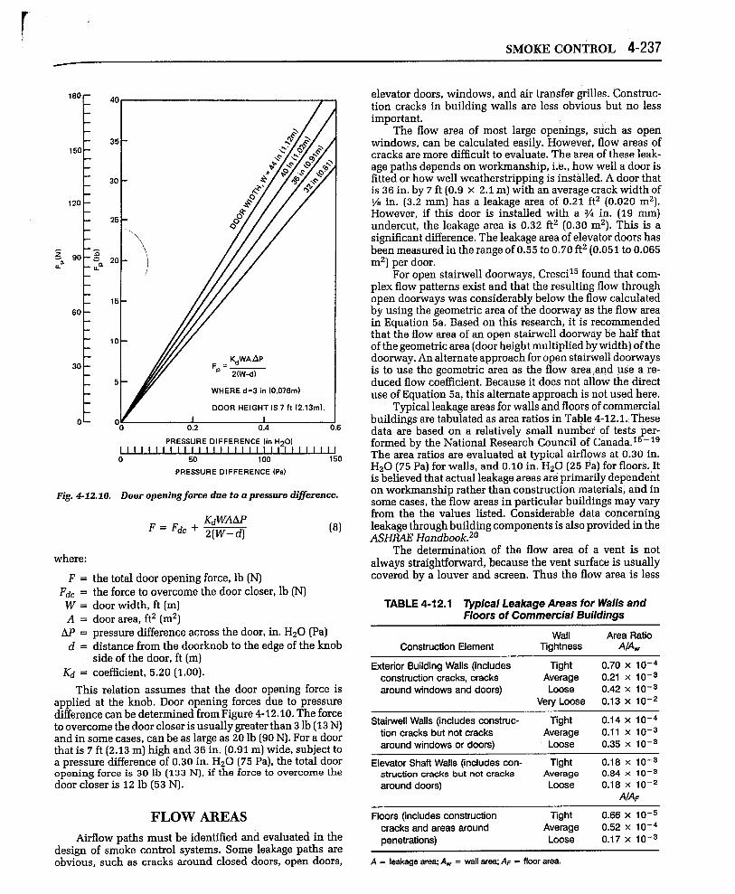
Fig. 4-12.10. Dooropeningforce duetoapressare difference.
(8)
where:
F=Fdc =w=A=
w=d=
Kd =
the total door opening force, lb (N)the force to overcome the door closer, lb (N)door width, ft (m)doorarea,ft2(m2)pressure difference across the door, in. H20 (Pa)distance from the doorknob to the edge of the knobside of the door, ft (m)coefficient, 5.20 (1.00).
This relation assumes that the door opening force isapplied at the knob. Door opening forces due to pressuredifference can be determined from Figure 4-12.10. The forceto overcome the door closer is usually greater than 3 lb (13 N)and in some cases, can be as large as 20 lb (9o N). For a doorthat is 7 ft (2.13 m) high and 36 in. (0.91 m) wide, subject toa pressure difference of 0.30 in. H20 (75 Pa), the total dooropening force is 30 lb (133 N), if the force to overcome thedoor closer is 12 lb (53 N).
FLOW AREAS
&rflowpaths must be identified and evaluated in thedesign of smoke control systems. Some leakage paths areobvious, such as cracks around closed doors, open doors,
elevator doors, windows, and air transfer grilles. Construc-tion cracks in building walls are less obvious but no lessimportant.
The flow area of most large openings, such as openwindows, can be calculated easily. However, flow areas ofcracks are more difficult to evaluate. The area of these leak-age paths depends on workmanship, i.e., how well a door isfitted or how well weatherstripping is installed. A door thatis 36 in. by 7 ft (0.9 X 2.1 m) with an average crack width of1Y8in. (3.2 mm) has a leakage area of 0.21 ftz (0.020 mz).However, if this door is installed with a % in. (19 mm)undercut, the leakage area is 0.32 ft2 (0.30 m2). This is asignificant difference. The leakage area of elevator doors hasbeen measured in the range of 0.55 to 0.70 ft2 (0.051 to 0.065mz) per door.
For open stairwell doorways, Cresci15 found that com-plex flow patterns exist and that the resulting flow throughopen doorways was considerably below the flow calculatedby using the geometric area of the doorway as the flow areain Equation 5a. Based on this research, it is recommendedthat the flow area of an open stairwell doorway lie half thatof the geometric area (door height multiplied by width) of thedoorway. An alternate approach for open stairwell doorwaysis to use the geometric area as the flow area and use d re-duced flow coefficient. Because it does not allow the directuse of Equation 5a, this alternate approach is n,otused here.
Typical leakage areas for walls and floors of commercialbuildings are tabulated as area ratios in Table 4-12.1. Thesedata are based on a relatively small number of tests per-formed by the National Research Council of Canada.16 -19The area ratios are evaluated at typical airflows at 0.30 in.H20 (75 Pa) for walls, and 0.10 in. H20 (25 Pa) for floors. ,Itis believed that actual leakage areas are primarily dependenton workmanship rather than construction materials, and insome cases, the flow areas in particular buildings may varyfrom the the values listed. Considerable data concerningleakage through building components is also provided in theASHRAE Handbook.20
The determination of the flow area of a vent is notalways straightforward, because the vent surface is usuallycovered by a louver and screen. Thus the flow area is less
TABLE 4-12.1 Typical Leakage Areas for Walls andFloors of Commercial Buildings
Wall Area RatioConstruction Element Tightness A/Aw
Exterior Building Walls (includes Tight 0.70 x 10⁻⁴construction cracks, cracks Average 0.21 x 10⁻³around windows and doors) Loose 0.42 X 10⁻³
Very Loose 0.13 x 10⁻²
Stairwell Walls (includes construc- Tight 0.14 x 10⁻⁴tion cracks but not cracks Average 0.11x 10⁻³around windows or doors) Loose 0.35 x 10⁻³
Elevator Shaft Walls (includes con- Tight 0.18 X 10⁻³struction cracks but not cracks Average o.e4 x 10-3
around doors) Loose 0.18 X 10⁻²A/AF
Floors (includes construction Tight 0.66 x 10⁻⁵cracks and areas around Average 0.52 X 10⁻⁴penetrations) Loose 0.17 x 10⁻³
A = leakage araq Aw = wall are% AF = floor area.

4-238 DESIGN CALCULATIONS
than the vent area (vent height multiplied by width). Be-cause the slats in louvers are frequently slanted, calculationof the flow area is further complicated, Manufacturers’ datashould be sought for specific information.
EFFECTIVE FLOW AREAS
The concept of effective flow areas is quite useful for anal-ysis of smoke control systems, The various paths of smokemovement in the system can be parallel with one another, inseries, or a combination of parallel and series paths, The effec-tive flow area of a given system of flow paths is the area of asingle opening that results in the same flow as the given systemwhen subjected to the same pressure difference over the totalsystem of flow paths. This concept is similar to an effectiveresistance of a system of electrical resistances.
The effective area, Ae, for the three parallel leakage areasof Figure 4-12.11 is
Ae=Al+A~+A3 (9)
If Al is 1.08ftz (0.10 mz) and AZ and A3 are 0.54ftz(0.05mz) each, then the effective flow area, A,, is 2.16ftz(0.20mz).
Equation 9 can be extended to any number of flow pathsin parallel; i.e., it can be stated that the effective area is thesum of the individual leakage paths.
Ae=~Ai (lo)j=l
where n is the number of flow areas, Ai, in parallel.
A,
PRESSURIZEDSPACE
A:
Fig. 4-12.11. Leakage paths in parallel.
AZ
Q1
PRESSURIZEDSPACE
--%3
OUTSIDE
Fig. 4-12.12. Leakage paths in series.
Three leakage areas in series from a pressurized spaceare illustrated in Figure 4-12.12. The effective flow area ofthese paths is -
/4e=$+++ +-l/2( ) (11)1 2 3
The general rule for any number of leakage areas is
(12)
where n is the number of leakage areas, Ai,in series. Insmoke control analysis, there are frequently only two pathsin series. For this case, the effective leakage area is
‘e’v&& (13)
LZ’4MPLE 1:
Calculate the effective leakage area of two equal flowpaths of 0.2 ft2 in series. Let A = Al = AZ = 0.02 mz.
Ae=& $— = — = 0.15 ft2 (0,014m2)
&&”
\Calcula e the effective area of two flow paths in seriestwhere A1 = 0.22 ftz (0.02 mz) and A2 = 2.2 ft2 (0.2 m2).
“=* = 0.219ftz (0.0199 mz)
This example illustrates that when two areas are inseries and one is much larger than the other, the effectivearea is approximately equal to the smaller area.
The method of developing an effective area for a systemof both parallel and series paths is to systemically combinegroups of parallel paths and series paths. The system illus-trated in Figure 4-12.13 is analyzed as an example.

.
.JSMOKE CONTROL 4-239
‘6
t
‘6
Q3
t
A,
A3
Q,
t*2 ~ Q2
A4Al
PRESSURIZEDSPACE
Fig. 4-12.13. Combination of Ieakagepatbs inparrdlel andseries.
The figure shows that A2 and A3 are in parallel; there-fore, their effective area is
A23~ = A2 + A3
Areas A4, A5, and A6 are also in parallel, so their effec-tive area is
A45& ‘i’t4+/t5+/t6
These two effective areas are in series with Al. There-fore, the effective flow area of the system is given by
Ae =(
- 1/2J--+ J--- +J-A: A;3. A;56 )e
JX4MPLE 3:
Calculate the effective area of the system in Figure4-12.13, if the leakage areas are Al = A2 = A3 = 0.22 ft2(0.02 m2) and A4 = A5 = A6 = 0.11ft2 (0.01 m2).
A23@= 0.44 ft2 (0,04 m2)
A456~= 0.33 ftz (O.O3mz)
A. = 0.16ft2 (0.015m2)
SYMMETRY
the floor plan of a multistory building that can be divided inone-half by a plane of symmetry. Flow areas on one side ofthe plane of symmetry are equal to corresponding flow areason the other side. For a building to be so treated, every floorof the building must be such that it can be divided in thesame manner by the plane of symmetry. If wind effects arenot considered in the analysis or if the wind direction isparallel to the plane of symmetry, then the airflow in onlyone-half of the building need be analyzed. It is not necessarythat the building be geometrically symmetric, as shown inFigure 4-12.14; it must be symmetric only with respect to flow.
DESIGN PARAMETERS:A GENERAL DISCUSSION
Ideally, building and fire codes should contain designparameters leading to the design of functional and econom-ical smoke control systems. Unfortunately, because smokecontrol is anew field, consensus has not yet been reached asto a definition of reasonable design parameters. Clearly, thedesigner has an obligation to adhere to any smoke controldesign criteria existing in appropriate codes or standards,but such criteria should be scrutinized to determine whetheror not they will result in an effective system. If necessary, thedesigner should seek a waiver of the local codes, to ensure aneffective smoke control system.
Five areas fbr which design parameters must be estab-lished are: (1) leakage areas, (z) weather data, (3) pressuredifferences, (4) airftow, and (5) number of open doors in thesmoke control system.
Leakage areas have already been discussed in this chap-ter. An additional consideration affecting pressure differ-ences and airflow is whether or not a window in the fire
STAIRS
A4PLANE OFSYMMETRY
!_
STAIRS
%
—-—
‘3
The concept of symmetry is useful in simplifying prob-lems and thereby easing solutions. Figure 4-12.14 illustrates Fig. 4-12.14. Baildingfloorpkm illustratingsymmetry concept.

4~240 DESIGN CALCULATIONS
compartment is broken. This factor is included in the fol-lowing discussion of these parameters. In the absence ofcode requirements for specific parameters, the following dis-cussion may be helpful to the designer.
Weather DataThe state-of-the-art of smoke control is such that little
consideration has been given to the selection of weather dataspecifically for the design of smoke control systems. How-ever, design temperatures for heating and cooling duringwinter and summer are recommended in the ASHRAEHandbook,zo For example, 99 and 97.5 percent winter de-sign temperatures have been provided. These values repre-sent the temperatures that are equaled or exceeded in theseportions of the heating season. *
A designer may wish to consider using these designtemperatures for the design of smoke control systems. Itshould be remembered that in a normal winter, there wouldbe approximately 22 hours at or below the 99 percent designvalue and approximately 54 hours at or below the 97.5 per-cent design value. Furthermore, extreme temperatures canbe considerably lower than the winter design temperatures.For example, the ASHRAE 99 percent design temperature forTallahassee, Florida is 27°F (– 3“C), but the lowest temper-ature observed there by the National Climatic Centerzl was– 2°F (– 19”C) on February 13, 1899.
Temperatures are generally below the design values forshort periods of time, and because of the thermal lag ofbuilding materials, these short intervals of low temperatureusually do not result in problems with respect to heatingsystems. However, the same cannot necessarily be said of asmoke control system. There is no time lag for a smokecontrol system, i.e., a smoke control system is subjected toall the forces of stack effect that exist at the moment thesystem is being operated. If the outside temperature is belowthe winter design temperature for which a smoke controlsystem was designed, then problems from stack effect mayresult. A similar situation can result with respect to summerdesign temperatures and reverse stack effect.
Wind data is needed for a wind analysis of a smokecontrol system. At present, no formal method of performingsuch an analysis exists, and the approach most generallytaken is to design the smoke control system so as to minimizeany effects of wind. The development of temperature andwind data for design of smoke control systems is an area forfuture effort.
Pressure DifferencesIt is appropriate to consider both the maximum and
minimum allowable pressure differences across the bound-aries of smoke control zones. The maximum allowable pres-sure difference should be a value that does not result inexcessive door opening forces, but it is difficult to determinewhat constitutes excessive door opening forces, Clearly, aperson’s physical condition is a major factor in determininga reasonable door opening force for that person, NFPA 10l@,fife Safety Code@,zz states that the force required to open anydoor in a means of egress shall not exceed 30 lb (133 N]. Inthe section of this chapter on purging, a method of determin-ing the door opening force is provided.
* The heating season usually consists of three winter months. Amoreexact definitionof these temperaturesis availablein Chapter24of theASHRAE Handbook—1985 Fundamentals.20
The criterion used in this chapter for selecting a mini.mum allowable pressure difference across a boundq of asmoke control system is that no smoke leakage should occurduring building evaluation. ** In this case, the smoke con.trol system must produce sufficient pressure differences sothat it is not overcome by the forces of wind, stack effect, orbuoyancy of hot smoke, The pressure differences due towind and stack effect can become very large in the event of abroken window in the fire compartment. Evaluation of thesepressure differences depends on evacuation time, rate of firegrowth, building configuration, and the presence of a firesuppression system. In the absence of a formal method ofanalysis, such evaluation must of necessity be based onexperience and engineering judgment.
A method for determining the pressure difference acrossa smoke barrier resulting from the buoyancy of hot gases isprovided in the section of this chapter regarding buoyancy.For a particular application, it maybe considered necessaryto design a smoke control system to withstand an intense firenext to a door at the boundary of a smoke control zone,Earlier in this chapter it was stated that in a series of full-scale fire tests, the maximum pressure difference reachedwas 0.064 in. H20 (16 Pa) across the burn room wall at theceiling. To prevent smoke infiltration, the smoke controlsystem should be designed to maintain a pressure slightlyhigher than that generated in fire conditions. A minimumpressure difference in the range of 0.08 to 0.10 in. H20 (20 to25 Pa) is suggested.
If a smoke control boundary is exposed to hot smokefrom a remote fire, a lower pressure difference due to buoy-ancy will result. For a smoke temperature of 7500F (400”C),the pressure difference caused by the smoke 5.o ft (1.53 m)above the neutral plane would be 0.04 in. H20 (10 Pa). In thissituation, it is suggested that the smoke control system bedesigned to maintain a minimum pressure in the range of0.06 to 0.08 in. H20 (15 to 20 Pa).
Water spray from fire sprinklers cools smoke from a build-ing fire and reduces the pressure differences due to buoyan~.III such a case it is probably wise to allow for pressure fluctu-ations. Accordingly, a minimum pressure difference in therange of 0.02 to 0.04 in. H20 (5 to 10 Pa) is suggested.
Windows in the fire compartment can break due toexposure to high temperature gases. In such cases, the pres-sure due to the wind on the building exterior can be deter-mined from Equation 3. If this window is the only opening tothe outside on the fire floor and the window faces into thewind, the boundary of the smoke control system could besubjected to higher pressures. One possible solution is tovent the fire floor on all sides to relieve such pressures. For abuilding that is much longer than it is wide, it maybe nec-essary to vent only on the two longer sides.
In addition to wind effects, stack effect can be in-creased in the event of a broken fire compartment window.With a fire on a lower floor during cold weather, stackeffect will increase pressures of the fire floor above sur-rounding spaces. Even though little research has beendone on the subject, the chances of a window breaking inthe fire compartment are reduced by the operation of fimsprinklers.
** Other criteria might involve maintaining a numberof smoke-freeegressroutesor preventingsmokeinfiltrationto a refugew“Discussion of all possible alternatives is beyondthe scope of ‘hischapter.

‘
SMOKE CONTROL 4-241
AirflowWhen the doors in the boundaries of smoke control
systems are open, smoke can flow into refuge areas or escaperoutes unless there is sufficient airflow through the opendoor to prevent smoke backflow, as discussed in the previ-ous section. One criterion for selecting a design velocitythrough an open door is that no smoke backflow shouldoccur during building evacuation. * Selection of this velocitydepends on evacuation time, rate of fire growth, building con-figuration, and the presence of a fire suppression system, In theabsence of a formal method of analysis, such an evacuationmust be based on experience and engineering judgment.
At present, there is still much to be learned about thecritical velocity needed to stop smoke backflow through anopen door. In the absence of a specific relationship for door-ways, the method of analysis presented for corridors in theearlier section regarding airflow can be used to yield approx-imate results. The width of the doorway may be used inplace of the width of the corridor. This technique is based onthe assumption that smoke properties are uniform across thecross-section. As previously illustrated, for a particular ap-plication, it may be considered necessary to design for anintensive fire, such as one with an energy release rate of 8 x10⁶ Btu/hr (2.4 MW). A critical velocity of approximately800 fpm (4 m/s)would be required to stop smoke.
In another application, it may be estimated that thebuilding would be subjected to a much less intense fire withan energy release rate of 427,000 Btu/hr(125 kW). To protectagainst smoke backflow during evacuation, the critical ve-locity would be 300 fpm (1.5 m/s).
In a sprinklered building, it might be considered thatthe smoke away from the immediate fire area would becooled to near ambient temperature by the spray from thesprinklers. In such a case a design velocity in the range of 50to 250 fpm (0.25 to 1.25 rids) may be used. Research isneeded to fully evaluate the effect of sprinklers on smokecontrol design parameters.
Number of Open DoorsThe need for air velocity through open doors in the
perimeter of a smoke control system has been discussed inthis chapter. Another design consideration is the number ofdoors that could be o~ened simultaneously when the smokecontrol system is operational. A design that allows for alldoors to be opened simultaneously may ensure that the sys-tem will always work, but it will probably add to the cost ofthe system.
Deciding on the number of doors that will be openedsimultaneously depends largely on the building occupancy.For example, in a densely populated building, it is verylikely that all the doors will be opened simultaneously dur-ing evacuation. However, if a staged evacuation plan or ref-uge area concept is incorporated in the building fire emer-gency plan, or if the building is sparsely occupied, only a fewof the doors maybe opened simultaneously during a fire.
PRESSURIZED STAIRWELLS
Many pressurized stairwells have been designed andbuilt with the goal of providing a smoke-free escape route in
* Othercriteriamightinclude the allowanceof limitedsmokeleak-ageintoareastobeprotected.Undersuch criteria,thetoxicitYoftiesmokeis a factorthat mustbe considered.
ROOFLEVEL
DUCTSHAFT
J-J”f
DUCT
1 /:w’FuGAL
Fig. 4-12.15. Stairwell pressurization bymrdtiple injection withthefan located at ground level.
the event of a building fire. A secondary objective is to pro-vide a smoke-free staging area for fire fighters. On the firefloor, a pressurized stairwell must maintain a positive pres-sure difference across a closed stairwell door so that smokeinfiltration is prevented.
During building fire situations, some stairwell doors areopened intermittently during evacuation and fire fighting,and some doors may even be blocked open. Ideally, when thestairwell door is opened on the fire floor, there should besufficient airflow through the door to prevent smoke back-flow. Designing such a system is difficult because of the largenumber of permutations of open stairwell doors and weatherconditions that affect the airflow through open doors.
Stairwell pressurization systems are divided into twocategories—single and multiple injection systems. A sin-gle injection system is one that has pressurized air sup-plied to the stairwell at one location; the most commoninjection point is at the top of the stairwell. Associatedwith this system is the potential for smoke feedback intothe pressurized stairwell, i.e., of smoke entering the stair-well through the pressurization fan intake. Therefore, thecapability of automatic shutdown in such an event shouldbe considered.
For tall stairwells, single injection systems can failwhen a few doors are open near the air supply injectionpoint. All of the pressurized air can be lost through the fewopen doors, and the system can then fail to maintain positivepressures across doors farther from the injection point. Sucha failure mode is especially likely with bottom injectionsystems when a ground level stairwell door is open.
For tall stairwells, supply air can be supplied at a num-ber of locations over the height of the stairwell. Figures4-12.15 and 4-12.16 are two examples of many possiblemultiple injection systems which can be used to overcomethe limitations of single injection systems. In these figuresthe supply duct is shown in a separate shaft, but systemshave been built that have eliminated the expense of a sepa-rate duct shaft by locating the supply duct in the stairwell