smt pick n place machine juki nozzle catalogue-rev-c3
TRANSCRIPT

Nozzle Application Catalogue
Sub Title
This catalogue describes a selection of our most widely used nozzles and their typical use in standard and special Surface Mount Applications.
Juki offers nozzles for specific applications and each special nozzle has been carefully engineered by our Application Specialists to ensure the highest quality product and ease of use.
A few examples of custom nozzles and their applications are illustrated in the section “ Special Applications “.
The “ Quick Reference Table “ provides the part numbers and descriptions.
This catalogue will be maintained periodically, please feel free to contact us for further assistance.
The Marketing Team [email protected] Automation Systems AG Weissensteinstrasse 81 CH-4500 Solothurn SWITZERLAND
TABLE OF CONTENTS
1 Nozzle types ........................................................................................................................................................................................ 2 1.1 Standard Application Nozzles..................................................................................................................................................... 2 1.1.1 Type 1xx .................................................................................................................................................................................. 2 1.1.2 Type 2xx .................................................................................................................................................................................. 2 1.1.3 Type 5xx .................................................................................................................................................................................. 2 1.2 Special Application Nozzles......................................................................................................................................................... 3 1.2.1 Slot nozzles.............................................................................................................................................................................. 3 1.2.2 Gripper nozzles ...................................................................................................................................................................... 3 1.2.3 Pipe nozzle............................................................................................................................................................................... 3
2 Nozzle selection ................................................................................................................................................................................ 4 2.1 Definition.......................................................................................................................................................................................... 4 2.2 Standard components Vs Standard nozzles............................................................................................................................. 4
3 Standard applications...................................................................................................................................................................... 5 3.1 Flat Chips ......................................................................................................................................................................................... 5 3.2 MELFS................................................................................................................................................................................................ 7 3.3 Tantalum Capacitors/ Inductors/ Potentiometers................................................................................................................. 8 3.4 Electrolytic Capacitors ................................................................................................................................................................. 9 3.5 Transistors/ Diodes .....................................................................................................................................................................11 3.6 Small Outlines ...............................................................................................................................................................................12 3.7 Plastic Leaded Chip Carriers.....................................................................................................................................................14 3.8 PLCC Sockets ...............................................................................................................................................................................15 3.9 Quad Flat Packs ............................................................................................................................................................................16 3.10 Ball Grid Arrays .........................................................................................................................................................................17 3.11 PCB Connectors........................................................................................................................................................................18
4 Customized nozzles.......................................................................................................................................................................20 4.1 Slot Nozzles...................................................................................................................................................................................20 4.1.1 700 Models ............................................................................................................................................................................20 4.1.2 2000/ FX1 Models................................................................................................................................................................22 4.2 Gripper Nozzles...........................................................................................................................................................................24 4.2.1 700 Models ............................................................................................................................................................................24 4.2.2 2000/ FX1 Models................................................................................................................................................................26 4.3 Pipe Nozzles ..................................................................................................................................................................................27 4.3.1 700 Models ............................................................................................................................................................................27 4.3.2 2000/ FX1 Models................................................................................................................................................................28
5 Special Applications.......................................................................................................................................................................29
6 Quick reference table ...................................................................................................................................................................34 6.1 Standard Nozzles .........................................................................................................................................................................34 6.2 Gripper Nozzles...........................................................................................................................................................................35
2
Type 1xx, 2xx & 5xx
1 NOZZLE TYPES
Juki’s modular placement heads and a wide selection of nozzles provide effective placement solutions for the most comprehensive list of components in the electronic industry, including 0201 chips, fine pitch packages, advanced packages and odd form components.
The nozzles are classified into two major types. Standard Application Nozzles Special Application Nozzles
The nozzle body and the tip are made of copper alloy to ensure the pick reliability and nozzle durability. This feature guarantees an excellent stability of the narrow tip nozzles for 0201, 0402, 0603 chip components.
Fine pitch placement nozzle tips are mounted with polyurethane cups to avoid skewing, which permits accurate placement.
Each vacuum nozzle is numbered with reference to the machine model, type of placement head, profile of the nozzle tip and the suction area.
1.1 Standard Application Nozzles
The standard nozzles are designed for most typical SMT applications; the best selection should cover a wide variety of components.
The nozzle numbers 1xx, 2xx and 5xx are reserved for standard types.
Machine Model Applicable Nozzle Type 750 1xx 760 1xx and 2xx 2010 5xx 2020 5xx 2030 5xx 2040 5xx 2050 5xx 2060 5xx FX1 5xx
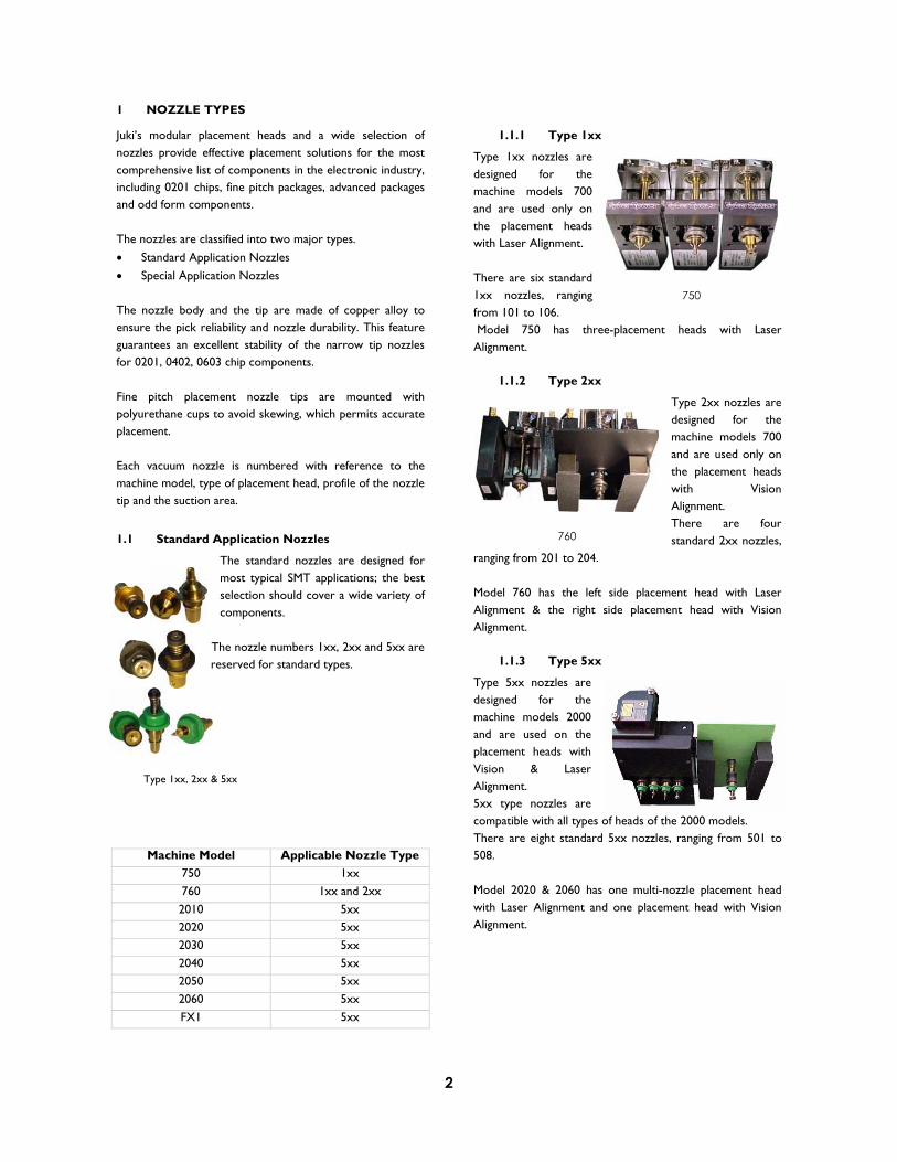
1.1.1 Type 1xx
Type 1xx nozzles are designed for the machine models 700 and are used only on the placement heads with Laser Alignment.
There are six standard 1xx nozzles, ranging from 101 to 106. Model 750 has three-placement heads with Laser Alignment.
1.1.2 Type 2xx
Type 2xx nozzles are designed for the machine models 700 and are used only on the placement heads with Vision Alignment.There are four standard 2xx nozzles,
ranging from 201 to 204.
Model 760 has the left side placement head with Laser Alignment & the right side placement head with Vision Alignment.
1.1.3 Type 5xx
Type 5xx nozzles are designed for the machine models 2000 and are used on the placement heads with Vision & Laser Alignment. 5xx type nozzles are compatible with all types of heads of the 2000 models. There are eight standard 5xx nozzles, ranging from 501 to 508.
Model 2020 & 2060 has one multi-nozzle placement head with Laser Alignment and one placement head with Vision Alignment.
750
760

3
Slot Nozzles - 700 Models
Gripper Nozzle - 700 Models
Pipe Nozzles - 700 Models
Gripper nozzle with a hybrid circuit
Pipe nozzle with a potentiometer
1.2 Special Application Nozzles
Odd-Form components, Special connectors are any devices that cannot be easily handled by standard nozzles, because of the varying shapes and sizes.
Juki have designed a wide range of Slot, Gripper and Pipe nozzles for handling special components. Each nozzle has been developed for a specific customer requirement.
Customized nozzles are compatible with the standard nozzle slider shaft and the standard Automatic Tool Changer. Each special nozzle package for 2000 series will be supplied with the nozzle configuration software.
In other words, JUKI customized nozzles have the ease of a Plug & Play feature without any modifications required to the standard machine configuration.
1.2.1 Slot nozzles
Slot nozzles have a tip with a narrow rectangular cross section for easy entry
into a slot.
These nozzles are generally used to
assemble a variety of board to board and ribbon cable connectors. A wide range of slot widths and slot lengths are available.
1.2.2 Gripper nozzles
Gripper nozzles have a fixed arm and a swing arm that enables it to grab odd shape components.
These nozzles are available with the gripping range from 0.8 mm to 5.2 mm. Odd form components, special connectors, hybrid circuits are typical
applications for Gripper nozzles.
1.2.3 Pipe nozzles
Pipe nozzles have big suction areas that facilitate the pick-up of large components. Varying inner diameters help to assemble different forms of sockets and shields.
A pipe nozzle with a set of interchangeable rubber tips is designed for mounting dies.
Slot nozzle applications with an inductor and a connector
Pipe nozzle with interchangeable rubber tips

4
NOZZLE SELECTION
1.3 Definition
Nozzle selection depends on the type and the outer dimensions of the components. The nozzle numbers and the vacuum pressures in the production program data are defined according to the minimum width or diameter D of the components to be picked. When selecting nozzles for non-standard shape components, the nozzle numbers and the vacuum pressures are to be entered manually, in the production program data.
1.4 Standard components Versus Standard nozzles
101
700 models Nozzle
100007000400250<1100
102 103/ 201 104/ 202 105/ 203 106/ 204
Component width (D in
>10000
2000 & FX1 models Nozzle
501 502 503 504 505 506 507 508
510 511

5
2 STANDARD APPLICATIONS
2.1 Flat Chip
Component Designation Length ( m) Width ( m) Height ( m) Nozzle Type
Flat Chip 0201 600 300 300 100 X 501
Flat Chip 0402 1000 500 200 101 X 502
Flat Chip 0603 1600 800 300 101 X 503
Flat Chip 0805 2000 1250 400 102 X 503
Flat Chip 1206 3200 1600 500 102 X 504
Flat Chip 1210 3200 2600 500 103 X 505
Flat Chip 2010 5000 2500 500 103 X 505
Flat Chip 2512 6300 3100 500 103 X 505
Nozzle Type Machinemodel
Tip Outer (mm)
Tip Inner (mm)
Applicable component Width
Vision Laser
101 750 760
1.0 0.4 D < 1.1 NA
102 750 760
1.5 1.0 1.1 D < 2.5 NA
103 750 760
3.0 1.7 2.5 D < 4.0 NA
501
2010 20202030 2040
2050 2060 FX1
0.7 * 0.4 2 * 0.2 D < 0.45
502
2010 20202030 2040
2050 2060 FX1
0.7 0.4 0.45 D < 0.75
503
2010 20202030 2040
2050 2060 FX1
1.0 0.6 0.75 D < 1.45

6
504
2010 20202030 2040
2050 2060 FX1
1.5 1.0 1.1 D < 2.5
505
2010 20202030 2040
2050 2060 FX1
3.5 1.7 2.5 D < 4.0

7
2.2 MELFS
Component Designation Length ( m) Width ( m) Height ( m) Nozzle Type
MELF 2000 1350 - 102 X 510
MELF 3200 1750 - 102 X 510
MELF 3500 1550 - 102 X 510
MELF 5900 2400 - 102 X 511
Nozzle Type Machinemodel
Tip Outer (mm)
Tip Inner (mm)
Applicable component Width
Vision Laser
102 750 760
1.5 1.0 1.1 D < 2.5 NA
510
2010 20202030 2040
2050 2060 FX1
1.5 0.6 1.6 D < 3.5
511
2010 20202030 2040
2050 2060 FX1
2.0 1.2 D 5.9
8
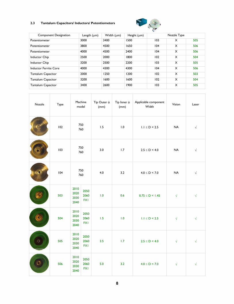
2.3 Tantalum Capacitors/ Inductors/ Potentiometers
Component Designation Length ( m) Width ( m) Height ( m) Nozzle Type
Potentiometer 3000 3400 1500 103 X 505
Potentiometer 3800 4500 1650 104 X 506
Potentiometer 4000 4500 2400 104 X 506
Inductor Chip 2500 2000 1800 102 X 504
Inductor Chip 3200 2500 2200 103 X 505
Inductor Ferrite Core 4000 4300 4300 104 X 506
Tantalum Capacitor 2000 1250 1200 102 X 503
Tantalum Capacitor 3200 1600 1600 102 X 504
Tantalum Capacitor 3400 2600 1900 103 X 505
Nozzle Type Machinemodel
Tip Outer (mm)
Tip Inner (mm)
Applicable component Width
Vision Laser
102 750 760
1.5 1.0 1.1 D < 2.5 NA
103 750 760
3.0 1.7 2.5 D < 4.0 NA
104 750 760
4.0 3.2 4.0 D < 7.0 NA
503
2010 20202030 2040
2050 2060 FX1
1.0 0.6 0.75 D < 1.45
504
2010 20202030 2040
2050 2060 FX1
1.5 1.0 1.1 D < 2.5
505
2010 20202030 2040
2050 2060 FX1
3.5 1.7 2.5 D < 4.0
506
2010 20202030 2040
2050 2060 FX1
5.0 3.2 4.0 D < 7.0
9
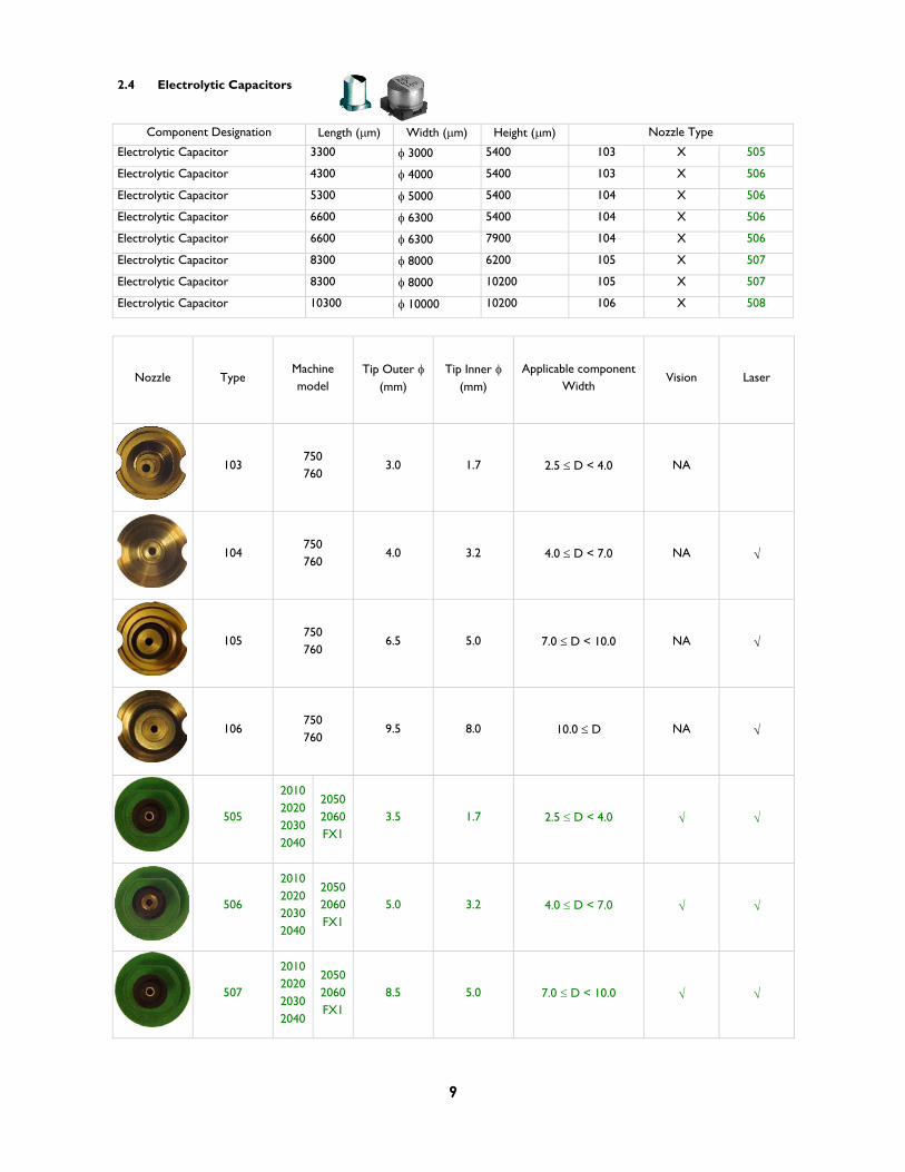
2.4 Electrolytic Capacitors
Component Designation Length ( m) Width ( m) Height ( m) Nozzle Type
Electrolytic Capacitor 3300 3000 5400 103 X 505
Electrolytic Capacitor 4300 4000 5400 103 X 506
Electrolytic Capacitor 5300 5000 5400 104 X 506
Electrolytic Capacitor 6600 6300 5400 104 X 506
Electrolytic Capacitor 6600 6300 7900 104 X 506
Electrolytic Capacitor 8300 8000 6200 105 X 507
Electrolytic Capacitor 8300 8000 10200 105 X 507
Electrolytic Capacitor 10300 10000 10200 106 X 508
Nozzle Type Machinemodel
Tip Outer (mm)
Tip Inner (mm)
Applicable component Width
Vision Laser
103 750 760
3.0 1.7 2.5 D < 4.0 NA
104 750 760
4.0 3.2 4.0 D < 7.0 NA
105 750 760
6.5 5.0 7.0 D < 10.0 NA
106 750 760
9.5 8.0 10.0 D NA
505
2010 20202030 2040
2050 2060 FX1
3.5 1.7 2.5 D < 4.0
506
2010 20202030 2040
2050 2060 FX1
5.0 3.2 4.0 D < 7.0
507
2010 20202030 2040
2050 2060 FX1
8.5 5.0 7.0 D < 10.0

10
508
2010 20202030 2040
2050 2060 FX1
9.5 8.0 10.0 D
11
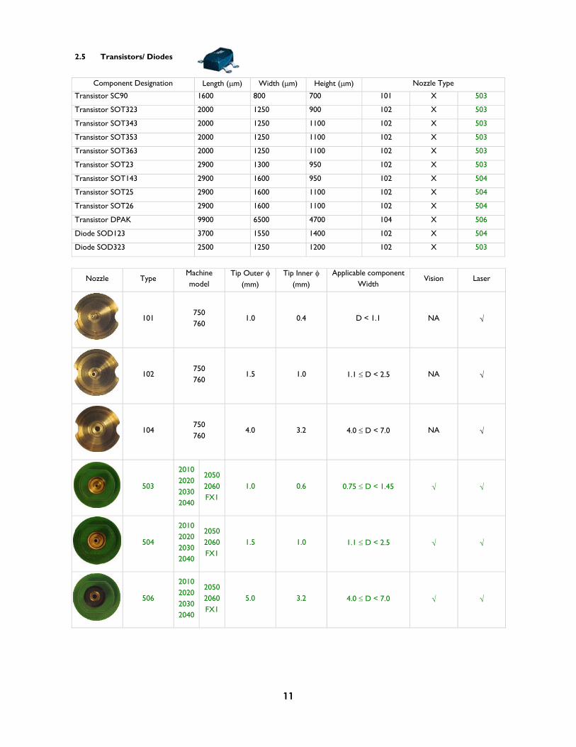
2.5 Transistors/ Diodes
Component Designation Length ( m) Width ( m) Height ( m) Nozzle Type
Transistor SC90 1600 800 700 101 X 503
Transistor SOT323 2000 1250 900 102 X 503
Transistor SOT343 2000 1250 1100 102 X 503
Transistor SOT353 2000 1250 1100 102 X 503
Transistor SOT363 2000 1250 1100 102 X 503
Transistor SOT23 2900 1300 950 102 X 503
Transistor SOT143 2900 1600 950 102 X 504
Transistor SOT25 2900 1600 1100 102 X 504
Transistor SOT26 2900 1600 1100 102 X 504
Transistor DPAK 9900 6500 4700 104 X 506
Diode SOD123 3700 1550 1400 102 X 504
Diode SOD323 2500 1250 1200 102 X 503
Nozzle Type Machinemodel
Tip Outer (mm)
Tip Inner (mm)
Applicable component Width
Vision Laser
101 750 760
1.0 0.4 D < 1.1 NA
102 750 760
1.5 1.0 1.1 D < 2.5 NA
104 750 760
4.0 3.2 4.0 D < 7.0 NA
503
2010 20202030 2040
2050 2060 FX1
1.0 0.6 0.75 D < 1.45
504
2010 20202030 2040
2050 2060 FX1
1.5 1.0 1.1 D < 2.5
506
2010 20202030 2040
2050 2060 FX1
5.0 3.2 4.0 D < 7.0
12
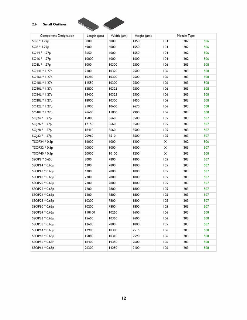
2.6 Small Outlines
Component Designation Length ( m) Width ( m) Height ( m) Nozzle Type
SO6 * 1.27p 3800 6000 1450 104 202 506
SO8 * 1.27p 4900 6000 1550 104 202 506
SO14 * 1.27p 8650 6000 1550 104 202 506
SO16 * 1.27p 10000 6000 1600 104 202 506
SO8L * 1.27p 8000 10300 2500 106 203 508
SO14L * 1.27p 9100 10320 2500 106 203 508
SO16L * 1.27p 10280 10300 2500 106 203 508
SO18L * 1.27p 11550 10300 2500 106 203 508
SO20L * 1.27p 12800 10325 2500 106 203 508
SO24L * 1.27p 15400 10325 2500 106 203 508
SO28L * 1.27p 18000 10300 2450 106 203 508
SO32L * 1.27p 21000 10600 2670 106 203 508
SO40L * 1.27p 26600 11800 2900 106 203 508
SOJ24 * 1.27p 15880 8660 3500 105 203 507
SOJ26 * 1.27p 17150 8660 3500 105 203 507
SOJ28 * 1.27p 18410 8660 3500 105 203 507
SOJ32 * 1.27p 20960 8510 3500 105 203 507
TSOP24 * 0.5p 16000 6000 1200 X 202 506
TSOP32 * 0.5p 20000 8000 1000 X 203 507
TSOP40 * 0.5p 20000 10100 1200 X 203 508
SSOP8 * 0.65p 3000 7800 1800 105 203 507
SSOP14 * 0.65p 6200 7800 1800 105 203 507
SSOP16 * 0.65p 6200 7800 1800 105 203 507
SSOP18 * 0.65p 7200 7800 1800 105 203 507
SSOP20 * 0.65p 7200 7800 1800 105 203 507
SSOP22 * 0.65p 9200 7800 1800 105 203 507
SSOP24 * 0.65p 9200 7800 1800 105 203 507
SSOP28 * 0.65p 10200 7800 1800 105 203 507
SSOP30 * 0.65p 10200 7800 1800 105 203 507
SSOP34 * 0.65p 118100 10250 2600 106 203 508
SSOP36 * 0.65p 15600 10350 2600 106 203 508
SSOP38 * 0.65p 12600 7800 1800 105 203 507
SSOP44 * 0.65p 17900 10300 2515 106 203 508
SSOP48 * 0.65p 15880 10310 2590 106 203 508
SSOP56 * 0.65P 18400 19350 2600 106 203 508
SSOP64 * 0.65p 26300 14250 2100 106 203 508

13
Nozzle Type Machinemodel
Tip Outer (mm)
Tip Inner (mm)
Applicable component Width
Vision Laser
104 750 760
4.0 3.2 4.0 D < 7.0 NA
105 750 760
6.5 5.0 7.0 D < 10.0 NA
106 750 760
9.5 8.0 10.0 D NA
202 760 5.5 3.2 4.0 D < 7.0
203 760 8.5 5.0 7.0 D < 20.0
506
2010 20202030 2040
2050 2060 FX1
5.0 3.2 4.0 D < 7.0
507
2010 20202030 2040
2050 2060 FX1
8.5 5.0 7.0 D < 10.0
508
2010 20202030 2040
2050 2060 FX1
9.5 8.0 10.0 D

14
2.7 Plastic Leaded Chip Carriers
Component Designation Length ( m) Width ( m) Height ( m) Nozzle Type
PLCC20 * 1.27p 9850 9850 4350 105 203 507
PLCC28 * 1.27p 12350 12350 4350 106 203 508
PLCC44 * 1.27p 17550 17550 4350 106 203 508
PLCC52 * 1.27p 20050 20050 4600 106 204 508
PLCC68 * 1.27P 25150 25150 4600 106 204 508
PLCC84 * 1.27p 30230 30230 4600 106 204 508
PLCC100 * 1.27p 35350 35350 4600 106 204 508
PLCC124 * 1.27p 42950 42950 4600 106 204 508
Nozzle Type Machinemodel
Tip Outer (mm)
Tip Inner (mm)
Applicable component Width
Vision Laser
105 750 760
6.5 5.0 7.0 D < 10.0 NA
106 750 760
9.5 8.0 10.0 D NA
203 760 8.5 5.0 7.0 D < 20.0
204 760 9.5 8.0 20.0 D
507
2010 20202030 2040
2050 2060 FX1
8.5 5.0 7.0 D < 10.0
508
2010 20202030 2040
2050 2060 FX1
9.5 8.0 10.0 D

15
2.8 PLCC Sockets
Component Designation Length ( m) Width ( m) Height ( m) Nozzle Type
Socket PLCC28 17000 17000 1500 106 203 508
Socket PLCC32 20300 17800 1500 106 203 508
Socket PLCC44 22900 22900 1500 106 204 508
Socket PLCC52 25500 25500 1500 106 204 508
Socket PLCC68 30500 30500 1500 106 204 508
Socket PLCC84 35700 35700 1500 106 204 598
Nozzle Type Machinemodel
Tip Outer (mm)
Tip Inner (mm)
Applicable component Width
Vision Laser
106 750 760
9.5 8.0 10.0 D NA
203 760 8.5 5.0 7.0 D < 20.0
204 760 9.5 8.0 20.0 D
508
2010 20202030 2040
2050 2060 FX1
9.5 8.0 10.0 D

16
2.9 Quad Flat Packs
Component Designation Length ( m) Width ( m) Height ( m) Nozzle Type
TQFP32 * 0.8p 7000 7000 1000 105 202 507
TQFP44 * 0.8p 10000 10000 1000 106 203 508
TQFP48 * 0.5p 7000 7000 1000 X 202 507
TQFP52 * 0.65p 10000 10000 1000 106 203 508
TQFP64 * 0.4p 7000 7000 1000 X 202 507
TQFP80 * 0.4p 10000 10000 1000 X 203 508
TQFP100 * 0.5p 19700 19700 1000 X 203 508
TQFP120 * 0.4p 15700 15700 1000 X 203 508
TQFP144 * 0.5p 20000 20000 1000 X 203 508
QFP44 * 0.8p 10000 10000 2000 106 203 508
QFP52 * 0.65p 10000 10000 2000 106 203 508
QFP64 * 0.8p 14000 14000 2000 106 203 508
QFP80 * 0.8p 20000 14000 2700 106 203 508
QFP100 * 0.65p 20000 14000 2700 106 203 508
Nozzle Type Machinemodel
Tip Outer (mm)
Tip Inner (mm)
Applicable component Width
Vision Laser
105 750 760
6.5 5.0 7.0 D < 10.0 NA
106 750 760
9.5 8.0 10.0 D NA
202 760 5.5 3.2 4.0 D < 7.0
203 760 8.5 5.0 7.0 D < 20.0
507
2010 20202030 2040
2050 2060 FX1
8.5 5.0 7.0 D < 10.0
508
2010 20202030 2040
2050 2060 FX1
9.5 8.0 10.0 D
17
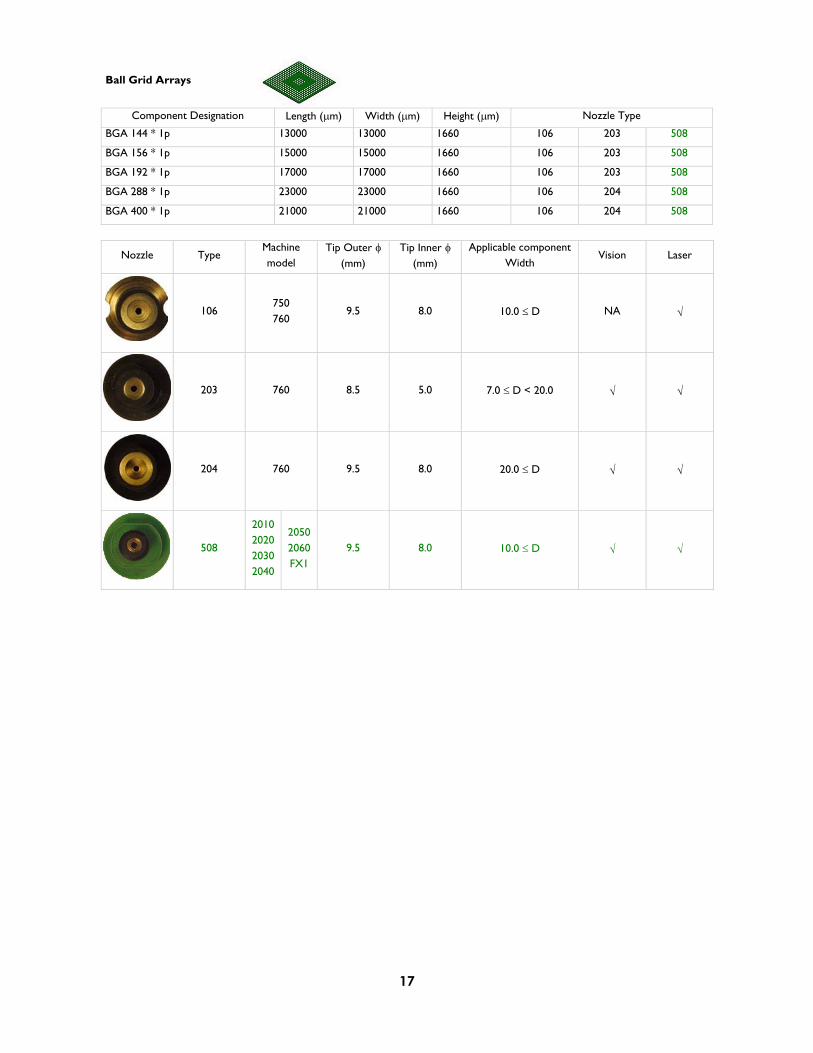
Ball Grid Arrays
Component Designation Length ( m) Width ( m) Height ( m) Nozzle Type
BGA 144 * 1p 13000 13000 1660 106 203 508
BGA 156 * 1p 15000 15000 1660 106 203 508
BGA 192 * 1p 17000 17000 1660 106 203 508
BGA 288 * 1p 23000 23000 1660 106 204 508
BGA 400 * 1p 21000 21000 1660 106 204 508
Nozzle Type Machinemodel
Tip Outer (mm)
Tip Inner (mm)
Applicable component Width
Vision Laser
106 750 760
9.5 8.0 10.0 D NA
203 760 8.5 5.0 7.0 D < 20.0
204 760 9.5 8.0 20.0 D
508
2010 20202030 2040
2050 2060 FX1
9.5 8.0 10.0 D
18
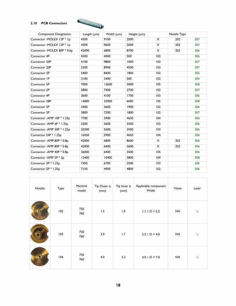
2.10 PCB Connectors
Component Designation Length ( m) Width ( m) Height ( m) Nozzle Type
Connector -MOLEX 12P * 1p 4500 9100 2000 X 202 507
Connector -MOLEX 12P * 1p 4500 9600 2000 X 202 507
Connector -MOLEX 80P * 0.6p 42000 6800 8700 X 202 506
Connector 4P 4500 4000 500 102 506
Connector 20P 4100 9800 1000 102 507
Connector 20P 2300 8900 4500 103 507
Connector 2P 5400 8400 1800 102 505
Connector 1P 3100 3400 500 102 505
Connector 5P 7000 12600 5000 105 508
Connector 2P 5800 7400 2700 103 507
Connector 4P 3600 4100 1700 103 506
Connector 28P 14800 32900 6000 105 508
Connector 2P 3400 5600 1900 102 506
Connector 2P 3800 7200 1800 102 507
Connector -AMP 10P * 1.25p 7700 5900 4650 104 506
Connector -AMP 6P * 1.25p 5200 5600 3500 103 506
Connector -AMP 30P * 1.25p 20200 5600 3500 103 506
Connector 24P * 1.25p 16450 5900 4650 104 506
Connector -AMP 80P * 0.8p 42000 6800 8600 X 202 506
Connector -AMP 80P * 0.8p 42000 6400 5600 X 202 506
Connector -AMP 40P * 0.8p 26000 6400 5500 105 506
Connector -AMP 5P * 2p 15400 10400 5800 104 508
Connector 2P * 1.25p 7450 6700 2500 103 506
Connector 2P * 1.25p 7150 4900 4800 102 506
Nozzle Type Machinemodel
Tip Outer (mm)
Tip Inner (mm)
Applicable component Width
Vision Laser
102 750 760
1.5 1.0 1.1 D < 2.5 NA
103 750 760
3.0 1.7 2.5 D < 4.0 NA
104 750 760
4.0 3.2 4.0 D < 7.0 NA
19
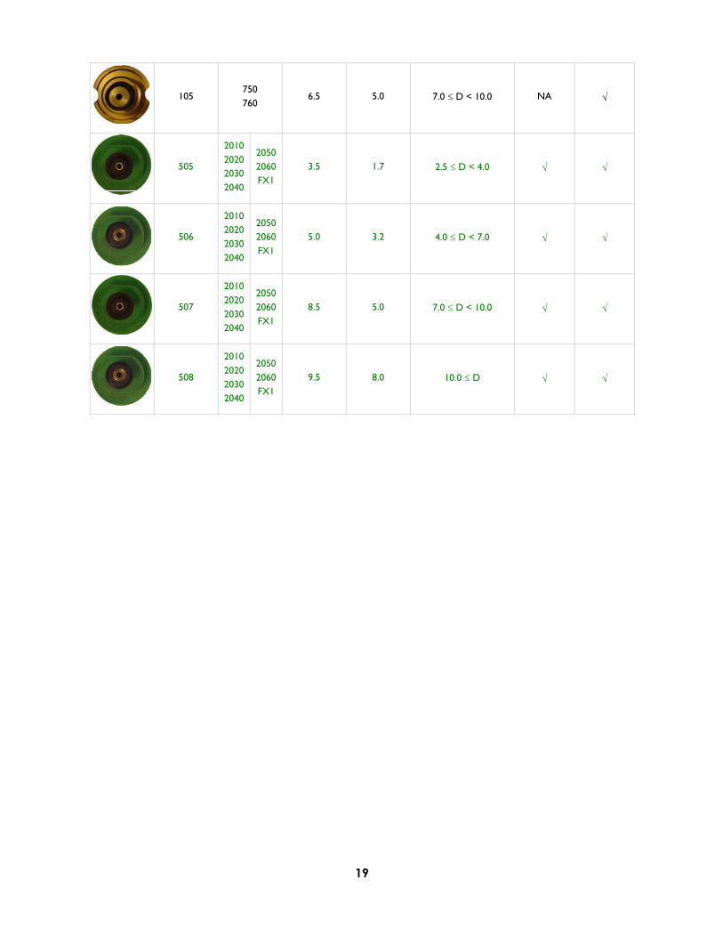
105 750 760
6.5 5.0 7.0 D < 10.0 NA
505
2010 20202030 2040
2050 2060 FX1
3.5 1.7 2.5 D < 4.0
506
2010 20202030 2040
2050 2060 FX1
5.0 3.2 4.0 D < 7.0
507
2010 20202030 2040
2050 2060 FX1
8.5 5.0 7.0 D < 10.0
508
2010 20202030 2040
2050 2060 FX1
9.5 8.0 10.0 D

20
3 CUSTOMIZED NOZZLES
3.1 Slot Nozzles
3.1.1 700 Models
Nozzle Type Machinemodel
Slot Width -W ( mm)
Slot Length -L (mm)
Applicable component Width
Vision Laser
67 750 760
1.0 8.0 > 1.0 NA
7750 760
1.0 9.0 > 1.0 NA
5750 760
1.6 9.0 > 1.6 NA
27 750 760
0.8 6.0 > 0.8 NA
21 760 3.1 9.0 > 3.1 NA
69 760 1.6 6.0 > 1.6 NA
84 760 1.0 9.0 > 1.0 NA
66 760 6.0 8.0 > 6.0 NA
LW

21
63 760 1.2 6.0 > 1.2 NA
22
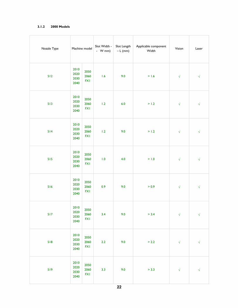
3.1.2 2000 Models
Nozzle Type Machine model Slot Width -- W mm)
Slot Length – L (mm)
Applicable component Width
Vision Laser
512
2010 2020 2030 2040
2050 2060 FX1
1.6 9.0 > 1.6
513
2010 2020 2030 2040
2050 2060 FX1
1.2 6.0 > 1.2
514
2010 2020 2030 2040
2050 2060 FX1
1.2 9.0 > 1.2
515
2010 2020 2030 2040
2050 2060 FX1
1.0 4.0 > 1.0
516
2010 2020 2030 2040
2050 2060 FX1
0.9 9.0 > 0.9
517
2010 2020 2030 2040
2050 2060 FX1
3.4 9.0 > 3.4
518
2010 2020 2030 2040
2050 2060 FX1
2.2 9.0 > 2.2
519
2010 2020 2030 2040
2050 2060 FX1
3.3 9.0 > 3.3

23
520
2010 2020 2030 2040
2050 2060 FX1
1.6 6.0 > 1.6
521
2010 2020 2030 2040
2050 2060 FX1
0.8 6.0 > 0.8
522
2010 2020 2030 2040
2050 2060 FX1
1.0 9.0 > 1.0
523
2010 2020 2030 2040
2050 2060 FX1
1.2 8.0 > 1.2
524
2010 2020 2030 2040
2050 2060 FX1
1.0 7.0 > 1.0
527
2010 2020 2030 2040
2050 2060 FX1
1.0 3.0 > 1.0
529
2010 2020 2030 2040
2050 2060 FX1
0.9 2.0 > 0.9
530
2010 2020 2030 2040
2050 2060 FX1
0.9 4.0 > 0.9
531
2010 2020 2030 2040
2050 2060 FX1
1.0 6.0 > 1.0
24
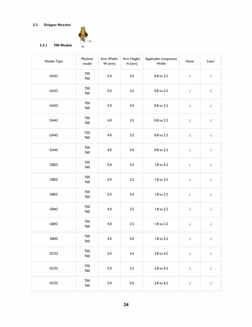
3.2 Gripper Nozzles
3.2.1 700 Models
Nozzle Type Machinemodel
Arm Width-W (mm)
Arm Height-H (mm)
Applicable component Width
Vision Laser
GA53 750 760
5.0 3.5 0.8 to 2.2
GA52 750 760
5.0 2.5 0.8 to 2.2
GA55 750 760
5.0 5.0 0.8 to 2.2
GA43 750 760
4.0 3.5 0.8 to 2.2
GA42 750 760
4.0 2.5 0.8 to 2.2
GA45 750 760
4.0 5.0 0.8 to 2.2
GB53 750 760
5.0 3.5 1.8 to 3.2
GB52 750 760
5.0 2.5 1.8 to 3.2
GB55 750 760
5.0 5.0 1.8 to 2.2
GB43 750 760
4.0 3.5 1.8 to 2.2
GB42 750 760
4.0 2.5 1.8 to 2.2
GB45 750 760
4.0 5.0 1.8 to 2.2
GC53 750 760
5.0 3.5 2.8 to 4.2
GC52 750 760
5.0 2.5 2.8 to 4.2
GC55 750 760
5.0 5.0 2.8 to 4.2
H
W

25
GC43 750 760
4.0 3.5 2.8 to 4.2
GC42 750 760
4.0 2.5 2.8 to 4.2
GC45 750 760
4.0 5.0 2.8 to 4.2
GD53 750 760
5.0 3.5 3.8 to 5.2
GD52 750 760
5.0 2.5 3.8 to 5.2
GD55 750 760
5.0 5.0 3.8 to 5.2
GD43 750 760
4.0 3.5 3.8 to 5.2
GD42 750 760
4.0 2.5 3.8 to 5.2
GD45 750 760
4.0 5.0 3.8 to 5.0
GE53 750 760
5.0 3.5 4.8 to 6.2
GE52 750 760
5.0 2.5 4.8 to 6.2
GE55 750 760
5.0 5.0 4.8 to 6.2
GE43 750 760
4.0 3.5 4.8 to 6.2
GE42 750 760
4.0 2.5 4.8 to 6.2
GE45 750 760
4.0 5.0 4.8 to 6.2
26
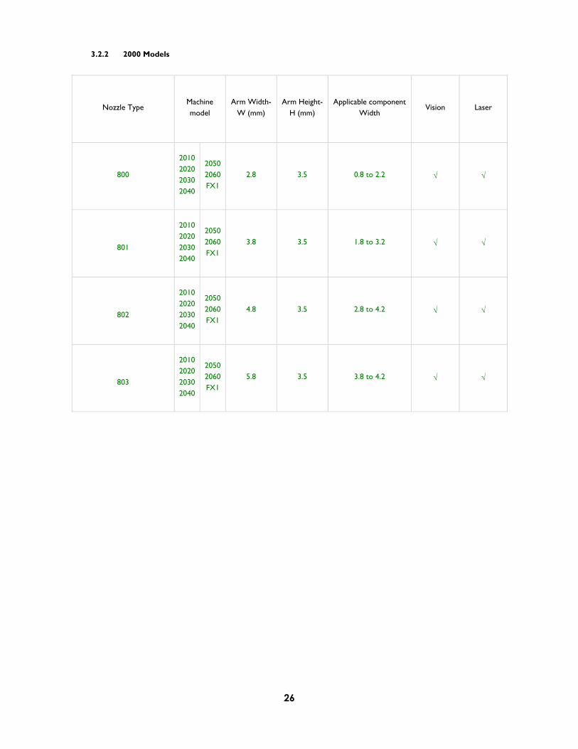
3.2.2 2000 Models
Nozzle Type Machinemodel
Arm Width-W (mm)
Arm Height-H (mm)
Applicable component Width
Vision Laser
800
2010 2020 2030 2040
2050 2060 FX1
2.8 3.5 0.8 to 2.2
801
2010 2020 2030 2040
2050 2060 FX1
3.8 3.5 1.8 to 3.2
802
2010 2020 2030 2040
2050 2060 FX1
4.8 3.5 2.8 to 4.2
803
2010 2020 2030 2040
2050 2060 FX1
5.8 3.5 3.8 to 4.2
27
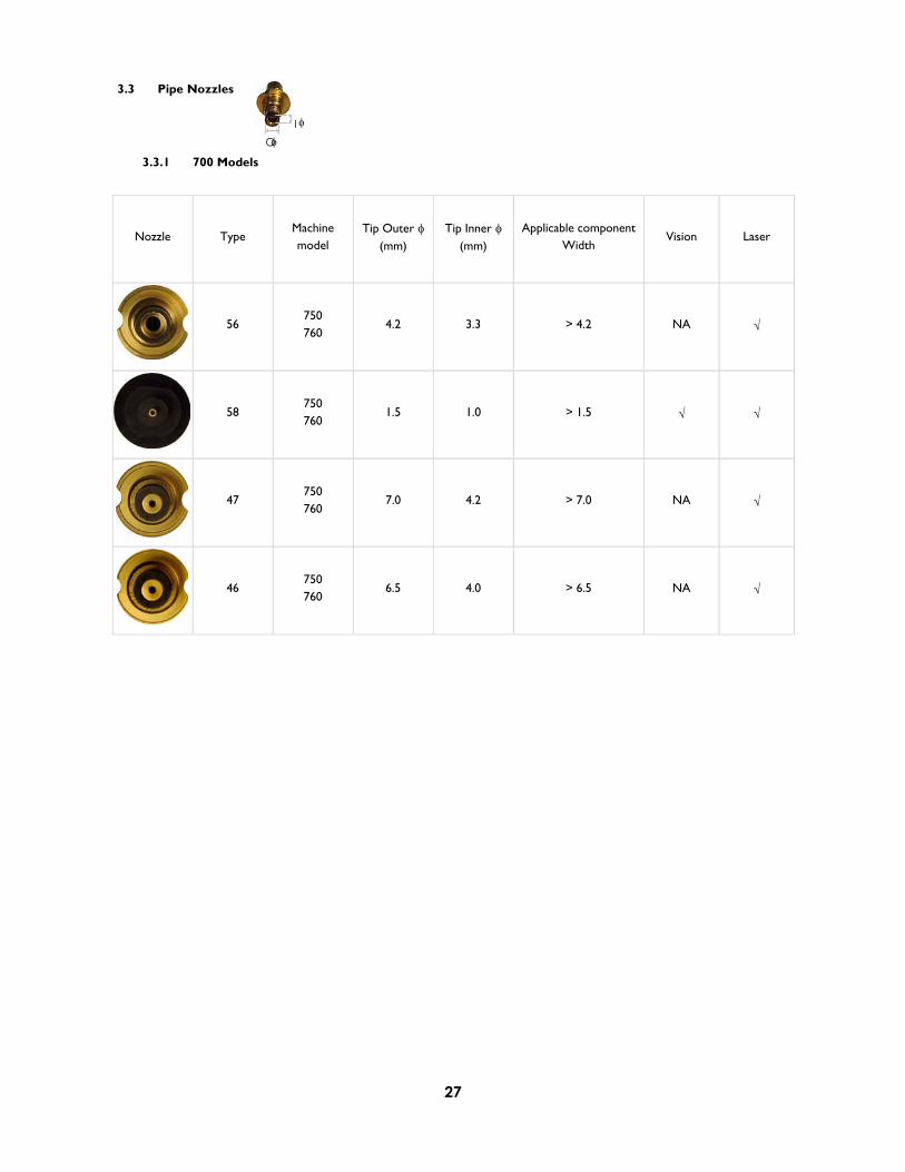
3.3 Pipe Nozzles
3.3.1 700 Models
Nozzle Type Machinemodel
Tip Outer (mm)
Tip Inner (mm)
Applicable component Width
Vision Laser
56 750 760
4.2 3.3 > 4.2 NA
58 750 760
1.5 1.0 > 1.5
47 750 760
7.0 4.2 > 7.0 NA
46 750 760
6.5 4.0 > 6.5 NA
IO

28
3.3.2 2000 Models
Nozzle Type Machinemodel
Tip Outer (mm)
Tip Inner (mm)
Applicable component Width
Vision Laser
525 2010 2020 2030 2040
2050 2060 FX1
3.0 1.5 > 3.0
526 2010 2020 2030 2040
2050 2060 FX1
3.5 1.5 > 3.5
528 2010 2020 2030 2040
2050 2060 FX1
2.0 0.7 > 2.0
29
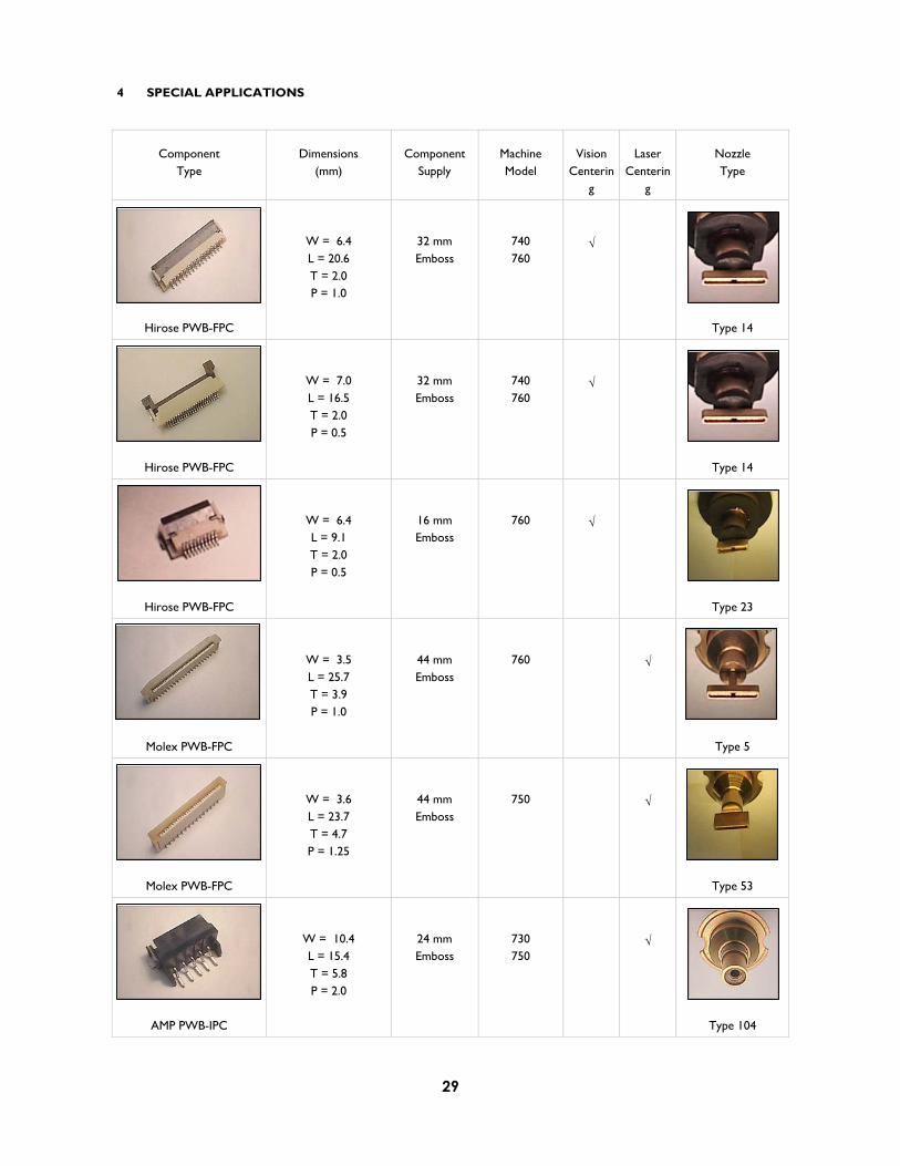
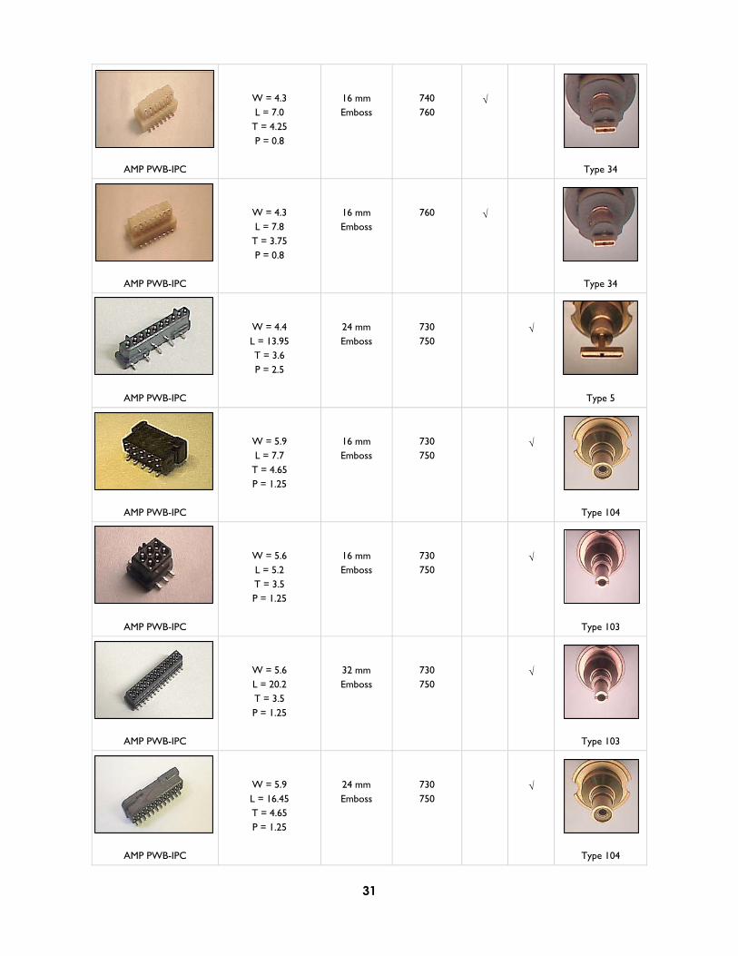
4 SPECIAL APPLICATIONS
ComponentType
Dimensions (mm)
Component Supply
Machine Model
VisionCenterin
g
Laser Centerin
g
NozzleType
Hirose PWB-FPC
W = 6.4 L = 20.6 T = 2.0 P = 1.0
32 mm Emboss
740 760
Type 14
Hirose PWB-FPC
W = 7.0 L = 16.5 T = 2.0 P = 0.5
32 mm Emboss
740 760
Type 14
Hirose PWB-FPC
W = 6.4 L = 9.1 T = 2.0 P = 0.5
16 mm Emboss
760
Type 23
Molex PWB-FPC
W = 3.5 L = 25.7 T = 3.9 P = 1.0
44 mm Emboss
760
Type 5
Molex PWB-FPC
W = 3.6 L = 23.7 T = 4.7 P = 1.25
44 mm Emboss
750
Type 53
AMP PWB-IPC
W = 10.4 L = 15.4 T = 5.8 P = 2.0
24 mm Emboss
730 750
Type 104
30
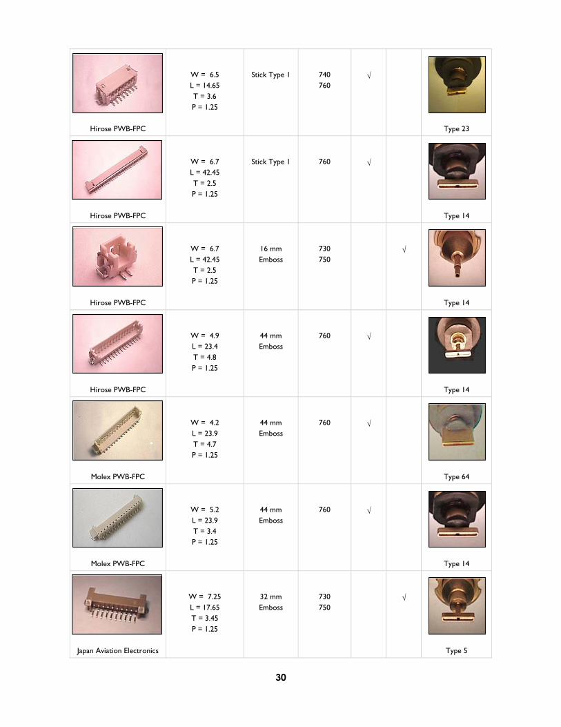
Hirose PWB-FPC
W = 6.5 L = 14.65 T = 3.6 P = 1.25
Stick Type 1 740 760
Type 23
Hirose PWB-FPC
W = 6.7 L = 42.45 T = 2.5 P = 1.25
Stick Type 1 760
Type 14
Hirose PWB-FPC
W = 6.7 L = 42.45 T = 2.5 P = 1.25
16 mm Emboss
730 750
Type 14
Hirose PWB-FPC
W = 4.9 L = 23.4 T = 4.8 P = 1.25
44 mm Emboss
760
Type 14
Molex PWB-FPC
W = 4.2 L = 23.9 T = 4.7 P = 1.25
44 mm Emboss
760
Type 64
Molex PWB-FPC
W = 5.2 L = 23.9 T = 3.4 P = 1.25
44 mm Emboss
760
Type 14
Japan Aviation Electronics
W = 7.25 L = 17.65 T = 3.45 P = 1.25
32 mm Emboss
730 750
Type 5
31
AMP PWB-IPC
W = 4.3 L = 7.0
T = 4.25 P = 0.8
16 mm Emboss
740 760
Type 34
AMP PWB-IPC
W = 4.3 L = 7.8
T = 3.75 P = 0.8
16 mm Emboss
760
Type 34
AMP PWB-IPC
W = 4.4 L = 13.95 T = 3.6 P = 2.5
24 mm Emboss
730 750
Type 5
AMP PWB-IPC
W = 5.9 L = 7.7
T = 4.65 P = 1.25
16 mm Emboss
730 750
Type 104
AMP PWB-IPC
W = 5.6 L = 5.2 T = 3.5 P = 1.25
16 mm Emboss
730 750
Type 103
AMP PWB-IPC
W = 5.6 L = 20.2 T = 3.5 P = 1.25
32 mm Emboss
730 750
Type 103
AMP PWB-IPC
W = 5.9 L = 16.45 T = 4.65 P = 1.25
24 mm Emboss
730 750
Type 104
32
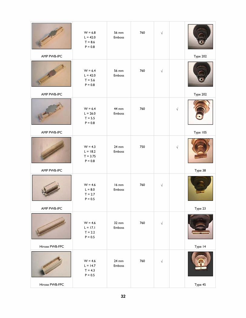
AMP PWB-IPC
W = 6.8 L = 42.0 T = 8.6 P = 0.8
56 mm Emboss
760
Type 202
AMP PWB-IPC
W = 6.4 L = 42.0 T = 5.6 P = 0.8
56 mm Emboss
760
Type 202
AMP PWB-IPC
W = 6.4 L = 26.0 T = 5.5 P = 0.8
44 mm Emboss
760
Type 105
AMP PWB-IPC
W = 4.3 L = 18.2 T = 3.75 P = 0.8
24 mm Emboss
750
Type 38
AMP PWB-IPC
W = 4.6 L = 8.0 T = 2.7 P = 0.5
16 mm Emboss
760
Type 23
Hirose PWB-FPC
W = 4.6 L = 17.1 T = 2.2 P = 0.5
32 mm Emboss
760
Type 14
Hirose PWB-FPC
W = 4.6 L = 14.7 T = 4.3 P = 0.5
24 mm Emboss
760
Type 45
33
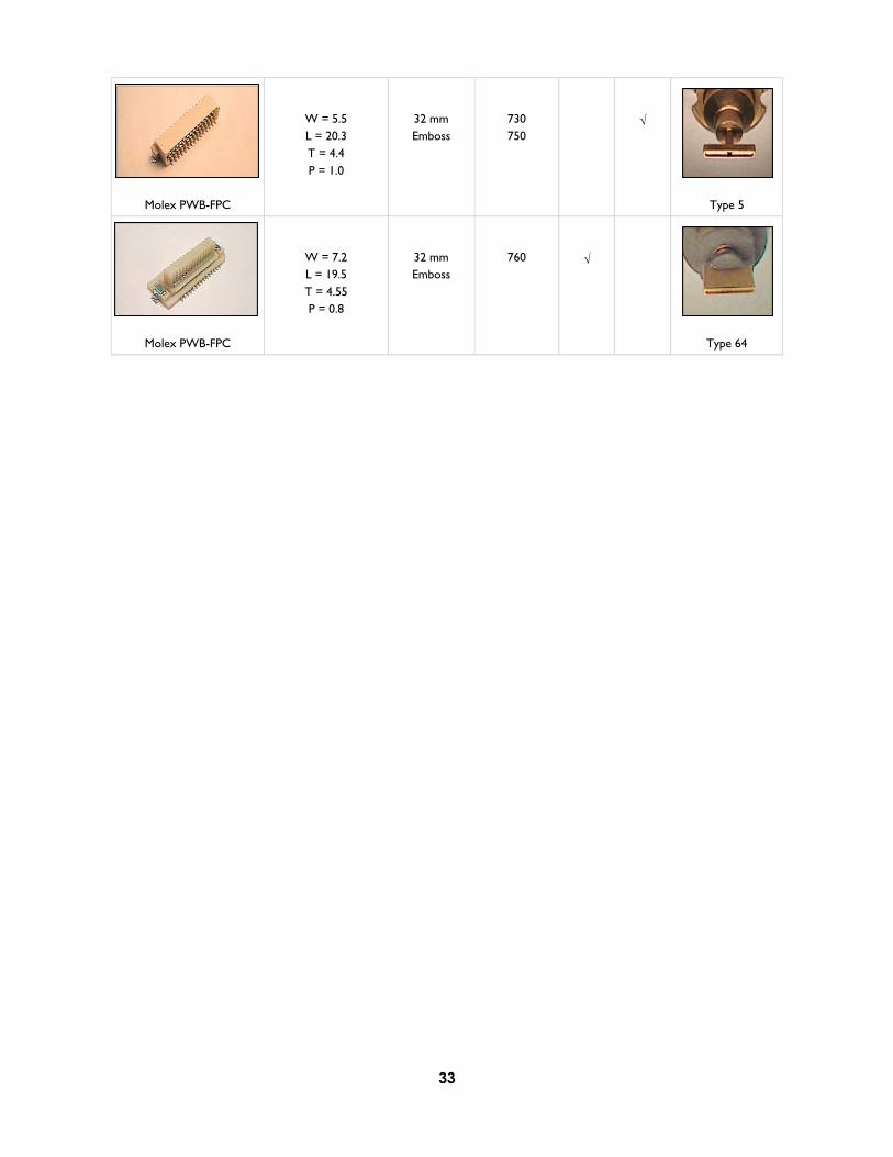
Molex PWB-FPC
W = 5.5 L = 20.3 T = 4.4 P = 1.0
32 mm Emboss
730 750
Type 5
Molex PWB-FPC
W = 7.2 L = 19.5 T = 4.55 P = 0.8
32 mm Emboss
760
Type 64

34
5 QUICK REFERENCE TABLE
5.1 Standard Nozzles
100 101 102 103 104 105 106 201 202 203 204
500 501 502 503 504 505 506 507 508 510 511
Standard Nozzle Configuration No
FX1 2050 2060 2010 2020 2030 2040 500 8* 4* 5* 5*501 502 4* 8* 2*503 4* 8* 2*504 8* 4* 5* 5*505 2* 2* 2* 1* 2* 2*506 2* 2* 2* 1* 2* 2*507 2* 2* 1* 2* 2*508 2* 1* 1* 1* 1* 1* 2*510 511
The first version of 500 series type nozzles were developed for KE-2000 conventional models (KE-2010, 2020, 2030 & 2040 machines).
JUKI have now released a new revision of 500 type nozzles with the machine models KE-2050, KE-2060 & FX-1.
Machine models
500 501 502 503 504 505 506 507 508 500 501 502 503 504 505 506 507 508KE-2010 X X X X X X X X XKE-2020 X X X X X X X X XKE-2030 X X X X X X X X XKE-2040 X X X X X X X X XKE-2050 KE-2060 FX1
= Compatible, X = Non-Compatible Nozzle # Part # Part #
500 E36087290A0 40011046 501 E36007290A0 40001339 502 E36017290A0 40001340 503 E36027290A0 40001341 504 E36037290A0 40001342 505 E36047290A0 40001343 506 E36057290A0 40001344 507 E36067290A0 40001345 508 E36077290A0 40001346
35
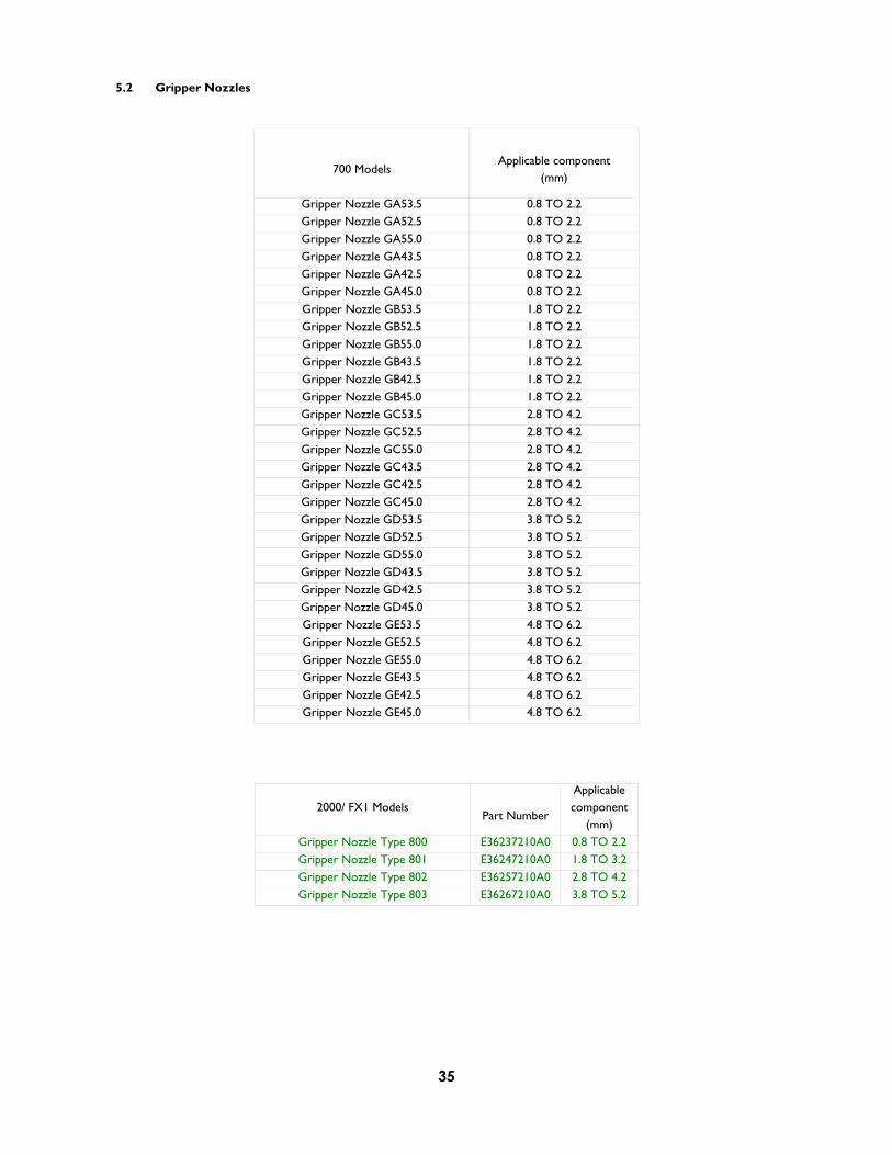
5.2 Gripper Nozzles
700 Models Applicable component
(mm)
Gripper Nozzle GA53.5 0.8 TO 2.2 Gripper Nozzle GA52.5 0.8 TO 2.2 Gripper Nozzle GA55.0 0.8 TO 2.2 Gripper Nozzle GA43.5 0.8 TO 2.2 Gripper Nozzle GA42.5 0.8 TO 2.2 Gripper Nozzle GA45.0 0.8 TO 2.2 Gripper Nozzle GB53.5 1.8 TO 2.2 Gripper Nozzle GB52.5 1.8 TO 2.2 Gripper Nozzle GB55.0 1.8 TO 2.2 Gripper Nozzle GB43.5 1.8 TO 2.2 Gripper Nozzle GB42.5 1.8 TO 2.2 Gripper Nozzle GB45.0 1.8 TO 2.2 Gripper Nozzle GC53.5 2.8 TO 4.2 Gripper Nozzle GC52.5 2.8 TO 4.2 Gripper Nozzle GC55.0 2.8 TO 4.2 Gripper Nozzle GC43.5 2.8 TO 4.2 Gripper Nozzle GC42.5 2.8 TO 4.2 Gripper Nozzle GC45.0 2.8 TO 4.2 Gripper Nozzle GD53.5 3.8 TO 5.2 Gripper Nozzle GD52.5 3.8 TO 5.2 Gripper Nozzle GD55.0 3.8 TO 5.2 Gripper Nozzle GD43.5 3.8 TO 5.2 Gripper Nozzle GD42.5 3.8 TO 5.2 Gripper Nozzle GD45.0 3.8 TO 5.2 Gripper Nozzle GE53.5 4.8 TO 6.2 Gripper Nozzle GE52.5 4.8 TO 6.2 Gripper Nozzle GE55.0 4.8 TO 6.2 Gripper Nozzle GE43.5 4.8 TO 6.2 Gripper Nozzle GE42.5 4.8 TO 6.2 Gripper Nozzle GE45.0 4.8 TO 6.2
2000/ FX1 Models Part Number
Applicablecomponent
(mm) Gripper Nozzle Type 800 E36237210A0 0.8 TO 2.2 Gripper Nozzle Type 801 E36247210A0 1.8 TO 3.2 Gripper Nozzle Type 802 E36257210A0 2.8 TO 4.2 Gripper Nozzle Type 803 E36267210A0 3.8 TO 5.2

36
Notes

37
Copyright 2004 by Juki Automation Systems AG All specifications are subject to change without prior notice.
Marketing Communications 19-May-04 Nozzle Catalogue Release Date: 25-May-04 Version: c 25/04/100/EU
Juki Automation Systems AG Weissensteinstrasse 81 CH-4500 Solothurn Phone +41 (0) 32 626 29 29 Fax +41 (0) 32 626 29 30
Juki Automation Systems GmbH Steinfeldstrasse 1 DE-90425 Nürnberg Phone +49 911 93 62 660 Fax +49 911 93 62 66 26
Juki Automation Systems Ltd. Leeds House, Amberly Court, Whitworth Road, Crawley UK-West Sussex, RH11 7XL Phone +44 (0) 1293 55 49 00 Fax +44 (0) 1293 55 49 01
Juki Automation Systems Inc. 507 Airport Boulevard Morrisville, NC 27560 USA Phone +1 (919) 460 0111 Fax +1 (919) 469 0480
Juki Corporation 8-2-1 Kokuryo-cho Chofu-shi, Tokyo 182-8655, Japan Phone +81 3 3480 3330 Fax +81 3 3488 1971
E-mail: [email protected] www.jas-smt.com