smta wisconsin chapter meeting printed circuit board considerations for lead free assembly dale lee...
TRANSCRIPT

SMTA Wisconsin Chapter SMTA Wisconsin Chapter MeetingMeeting
PRINTED CIRCUIT BOARD CONSIDERATIONS PRINTED CIRCUIT BOARD CONSIDERATIONS FOR LEAD FREE ASSEMBLYFOR LEAD FREE ASSEMBLY
Dale Lee
Bill Barthel
15 May, 2007

RoHS-OverviewRoHS-OverviewWhat is behind the drive for lead free products?Directive 2002/95/EC of the European Parliament and of the Council of
27 January 2003 on the restriction of the use of certain hazardous substances in electrical and electronic equipment. (RoHS--Reduction of Hazardous Substances)
Article 4-PreventionMember States shall ensure that, from 1 July 2006, new electrical and electronic equipment put on the market does not contain lead, mercury, cadmium, hexavalent chromium, Polybrominated Biphenyls (PBB) or Polybrominated Diphenyl Ethers (PBDE) specifically Penta PBDE and Octa PBDE
Certain end product categories are exempt until 2010
RoHS & Bromine FreeRoHS & Bromine Free
• Tetrabromobisphenol-A (TBBPA) Is The Leading Flame Retardant Used In Printed Circuit Boards (95%+) And Computer Chip Casings
• The Use Of TBBPA Is Currently Not Banned In Any Country In The World
• There Is Concern That RoHS Or Local Legislation May Be Revised To Prohibit All BFR’s
– This Is Considered Less Likely Based On Recent Risk Assessment By The EU

Halogen Free MaterialsHalogen Free Materials• All Major Laminate Manufacturers Have A Halogen Free Offering
– Brominated Flame Retardants Replaced Predominately With Phosphorous Based Material
• These Materials Are More Hydrophilic Than Brominated Materials– Lower Moisture Sensitivity Level Than Standard FR4 Material
(Some Lead Free FR4 Laminate Materials Are Also Hydrophilic)
• There Are Currently No Low Loss Systems That Are Bromine Free
• These Materials Typically Have A Shorter Shelf Life– Further Exacerbating Import And Inventory Issues For PCB Fabricator
• These Materials Are More Costly When Compared To Their Brominated Equivalent
• Halogen Free Materials Are Primarily Manufactured In Asia And Europe– Very Limited Market For Bromine Free Products In North America– Off-shore Supply Extends Lead Times Or Create Risk Buy Inventories

Halogen Free Material UsageHalogen Free Material Usage
• Use Of Halogen-free Materials Will Increase As Consumer Level Products Push To Be Halide Free (Design For Environment)– Apple Computer– Motorola– Nokia– Others
• iNEMI is sponsoring a project to defineand qualify materials– Outline key performance characteristics– Focus on Electrical characteristics, Delamination, and Via
Reliability– Determine compatibility with higher temperatures

Halide Free MaterialsHalide Free MaterialsThermal-Mechanical DataThermal-Mechanical Data
Isola IS500 170 180 350 2.8% >60 >60Nelco 4000-7 EF 155 165 425 3.5% >30 3Polyclad PCL-HF-571 165 340 2.9%* >30 3Hitachi BE-67-GH 145 - - 50 - -Nanya NPG-150 141 150 350 >60 >60
MATERIAL T260 T288Tg TMA
°CTg DSC
°CTd TGA
CTE by TMA
Based on Vendor Data
CTE by TMA = ambient to 288°C
*CTE by TMA = ambient to 260°C

Materials To Be AssessedMaterials To Be Assessed

Performance And Test CriteriaPerformance And Test Criteria

PCB Laminate FactorsPCB Laminate Factors
• Tg – Temperature where laminate changes rate of thermal expansion. Function of Resin Chemistry.
• Td – Decomposition temperature of laminate measured by weight loss by TGA. Function of Resin Chemistry.
• T260, T288 – Resistance to Delamination at elevated temperatures. Function of Resin Chemistry and board Design.

Thermal-Mechanical PropertiesThermal-Mechanical Properties• It Is Important To Understand How The Data Provided
By The Material Suppliers Was Generated – Differences In Test Methods, Samples Or Criteria Used Can
Effect Reported Values
• Comparison Of Data Should Be From Like Conditions And Methods, Or Differences Understood And Accounted For– Decomposition Temperature – Td
• Reported At 2% Or 5%
– Coefficient Of Thermal Expansion – CTE• Temperature Range; Prefer Room Temp To 288°C• Resin Content Of Sample
– Time To Delamination – T260 & T288• Heat Rise: Prefer 100°C Per Minute• Copper Clad Vs. Unclad Sample

DICY Cure High Tg FR4DICY Cure High Tg FR4TGA: Decomposition Temp TGA: Decomposition Temp

Phenolic Cure High Tg FR4Phenolic Cure High Tg FR4TGA: Decomposition TempTGA: Decomposition Temp

Decomposition TemperatureDecomposition Temperature
• When Printed Circuit Boards Are Exposed To Multiple Heating Cycles (Assembly, Rework and Lamination), Small Repeated Weight Losses Can Degrade The Reliability Of The PCB.
• The Difference Between Low Td Material With 2% Weight Loss And High Td Material With 0.5% Weight Loss Per Assembly Process Cycle Can Be The Difference Between Scrap And A Reliable Product.
Courtesy of Cookson

Time to DelaminationTime to Delamination
• For Lead Free Assembly, The IPC Requirement For Time To Delamination Tested At T288 Condition (288C) Should Be The Baseline Temperature
Courtesy of Cookson

Decomposition TemperatureDecomposition Temperature
• Minimum Decomposition Temperature (Td) Of 340C And Thermal Cycle Reliability
Courtesy of Cookson

Time to DelaminationTime to Delamination
• Delamination May Not Be Visible During Initial Assembly Process But Subsequent Processes Such As Component Rework And Replacement May Result In Visible PCB Delamination Or Blistering
• Tested To Higher Temperatures Comparable To Lead Free Assembly Temperatures Of T288 Condition, Many Of The Laminates Have Delamination Times Of Less Than 5 Minutes.
• Visible Carbonization Of The Epoxy Laminate And/Or Charring Exhibited
Glass Transition TemperatureGlass Transition Temperature
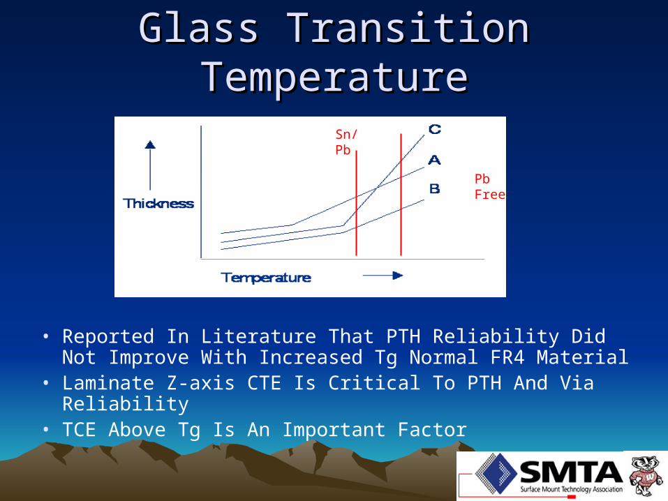
• Reported In Literature That PTH Reliability Did Not Improve With Increased Tg Normal FR4 Material
• Laminate Z-axis CTE Is Critical To PTH And Via Reliability• TCE Above Tg Is An Important Factor
Sn/Pb
Pb Free

Coefficient of Thermal Coefficient of Thermal ExpansionExpansion
0
10
20
30
40
50
60
Silicon Alumina Glass Copper Solder Epoxy
ppm/0C
Epoxy expansion can be modified by glass and filler content

TMA CurveTMA Curve
Z axis pre Tg
20°C – 185°C
84.3 ppm/°C
184.92°C
Z axis post Tg
185°C – 288°C
315 ppm/°C
Z axis Overall
20°C – 288°C
161 ppm/°C

Standard Loss MaterialStandard Loss MaterialThermal-Mechanical DataThermal-Mechanical Data
Dicy Cure 170 Tg FR4 160 170 290 4.4% <10 -Isola IS410 169 179 345 3.5% >27 5.2Polyclad 370HR 180 350 2.7% >30 7MEM 1755 173 177 364 3.0% >27 3.8Nelco 4000-11 170 175 360 3.2% 30 -Nanya NPN170 165 175 369 - - -Isola IS400 145 150 330 3.5% 60 10Polyclad 250HR 150 350 3.4% >27 4Nanya NPN150 145 156 367 - - -
MATERIALT260 T288Tg TMA
°CTg DSC
°CTd TGA
CTE by TMA
170°C Tg 150°C Tg
Standard Loss: Df 0.020 Dk 4.1 – 4.4
CTE by TMA = ambient to 288°C
Courtesy of Merix

Test Results 2000 IST High Tg FR-4Test Results 2000 IST High Tg FR-4
Standard Dicy based High Tg FR-4 showed about 70% drop in via fatigue life. Use NEMI Reflow For Lead Free Profile Testing.
Courtesy of Merix

Electrical PropertiesElectrical PropertiesDielectric Constant – Dk Or ErDissipation Factor – Df Or Loss Tangent
• Changes In Material Systems To Improve Thermal Resistance Can Alter Electrical Properties– Phenolic Systems Tend To Have Higher Df And Dk Values– Some Suppliers Use Fillers To Enhance CTE And Reduce Df,
This Typically Increases Dk
• It Is Important To Understand These Properties When Transitioning To Pb Free Materials
• However Subtle, Designs Which Maximize The Performance Of Traditional Epoxy May Be Affected By New Lead Free Compatible Materials

Electrical PropertiesElectrical PropertiesDk Df
MATERIAL 1 GHz 10 GHZ 1 GHz 10 GHzIsola FR 406 3.9 3.8 0.015 0.017Isola IS 400 4.3 - 0.017 -Polyclad 250HR 4.65 4.5 0.017 0.019Isola IS 410 4.1 4.0 0.020 0.023MEM 1755 4.4 4.2 0.020 0.023Polyclad 370HR 4.5 4.3 0.017 0.020Hitachi BE-67-GH 4.4 4.4 0.009 0.014Isola FR 408 3.7 3.65 0.012 0.014Polyclad Getek HR 3.9 3.8 0.009 0.011Nelco 4000-12 3.8 3.7 0.009 0.008Nelco 4000-13 3.8 3.5 0.010 0.012Isola IS 620 3.6 3.6 0.008 0.0085Polyclad LD-621 3.4 3.2 0.006 0.008Megtron 5 3.5 3.4 0.004 0.0085
Isola FR 406 3.9 3.8 0.015 0.017
Isola FR 410 4.1 4.0 0.020 0.023
Polyclad 370HR 4.5 4.3 0.017 0.020

Material PropertiesMaterial Properties
Courtesy of Isola

PCB FinishesPCB Finishes• Most Finishes are compatible with Lead Free
Assembly Process requirements– Immersion Silver
• Environment Exposure (Pollution) Sensitive– Sulfur, Chlorine, etc.
– ENIG / Electrolytic Gold/Nickel• Black Pad Issue
– Interest in electroless Ni/Pd/Au as an alternative to ENIG
• Severe Environmental Exposure (Pollution) Sensitive
– Organic Solder Preservative (OSP)• Limited number of heating cycle exposures• New High Temperature Compatible Formulas• Impacts Wave Solder Process Solderability

PCB FinishesPCB Finishes• Most Finishes are compatible with Lead
Free Assembly Process requirements– Immersion Tin
• Tin Whiskers• Limited Shelf Life
– Lead Free HASL• Limited Availability• Higher Cost Than Traditional Tin/Lead Coating

Lead Free Solder SpreadLead Free Solder Spread
• OSP And Immersion Ag Finishes Do Not Promote Lead Free Solder Spread (SMT & PTH)
• ENIG And Immersion Tin Have Similar Solder Spread To Traditional Tin Lead
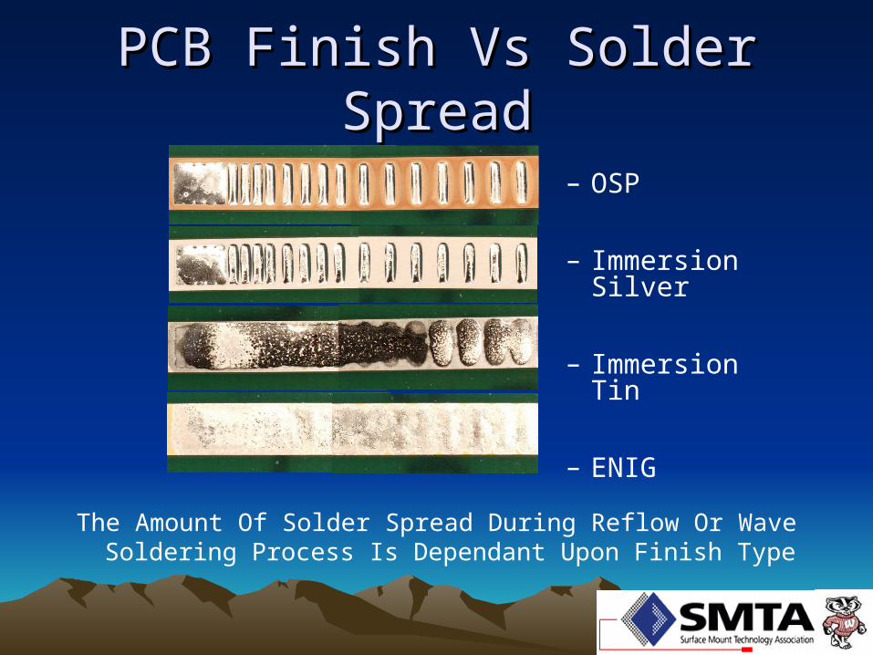
PCB Finish Vs Solder SpreadPCB Finish Vs Solder Spread
– OSP
– Immersion Silver
– Immersion Tin
– ENIG
The Amount Of Solder Spread During Reflow Or Wave Soldering Process Is Dependant Upon Finish Type

IPC – Lead Free Laminate IPC – Lead Free Laminate
• IPC Laminate/Prepreg Materials Subcommittee Proposal:
– Glass Transition Temperature 155 ºC – Decomposition Temperature 340 ºC – Z-Axis Expansion Alpha 1 (max/ ºC) 60 ppm– Z-Axis Expansion Alpha 2 (max/ ºC) 300 ppm– T260 (minutes) 30 min.– T288 (minutes) 15 min.– T300 (minutes) 2 min.
Missing from proposal is an assembly and rework process exposure test.

PCB Laminate SpecificationPCB Laminate Specification
• Old 4101A Spec Only Had 2 Major Classifications For FR4 Material - /24 & /26
• New 4101B Spec Has Multiple Classifications– Low Halide: /92 & /94 (P), /93 & /95 (Al(OH)3)– FR4 (w Inorganic Fillers): /97, /99, /101 & /126– FR4 (w/o Inorganic Fillers): /121, /124 & /129
(Note: All Low Halide Slash Sheets Are Multifunctional. FR4 Are Both Difunctional & Multifunctional By Slash Sheet

Industry Stance on Lead FreeIndustry Stance on Lead Free
• EMS Forum; A Group Of Leading EMS Providers Has Developed Guidelines For PCB Supplier’s Transitioning To Lead Free– While The Guideline Does Not State Specific Pass Fail Performance
Criteria For These Materials It Does Identify Critical Reliability Testing Using Preconditioning
– This Document Has Identified A Peak Reflow Temp. Of 260°C
• General Agreement Within Industry For The iNEMI Criteria With Peak Assembly Temperature Of 260°C

Lead Free Criteria Lead Free Criteria
• Materials Intended For Use In Lead Free Assembly Must Be Able To Survive Multiple Exposures At 260°C And Have Acceptable Post Assembly Reliability– Materials With Improved Thermal Mechanical
Properties Are Needed• A Variety Of Tests To Should Be Used To
Determine Lead Free Capability For Any Given Material
• No Single Test Or Material Attribute Can Assure Lead Free Assembly Compatibility– Need To Pass Multiple Tests

Test Protocol VariantTest Protocol Variant
• When Reviewing And Comparing Data Of Vendor Reports, It Is Important To Understand The Design And Assembly Parameters Of The Test Vehicles– Board Thickness And Layer Count Affect Thermal Mass– Drilled Hole Size – Surface Finish– Preconditioning Methods And Number Of Exposures
• Currently There Is No Industry Standard Test Methodology

Performance ConsiderationPerformance Consideration• Performance Requirements May Dictate Material
Selection – Mission Critical Applications; Military, Aerospace,
Medical• Decisions Should Be Conservative To Allow For A Safety Zone
– Non Fault Tolerant Systems Where Additional Reliability Requirements Are Specified• Mainframes, Servers, Communications Equipment, Automotive
– Life Expectancy Of The Product• Consumer Electronics Vs. System Electronics
– System Environment• Additional Performance Criteria Such As CAF
Resistance May Make Certain Materials More Appropriate

PCB Assembly ConsiderationPCB Assembly Consideration• Peak Reflow Temperature• Number Of Reflow Cycles
– Consider Build Short Scenarios• Unusual Or Special Assembly Processes That
Effect Thermal Exposures And Mechanical Loading
• Potential Rework Cycles And Processes– Including Up Rev And Part Change Outs– Moisture Sensitivity Level & Exposure Time– More important as value/reliability of the PCA
increases

PCB Thickness
Nu
mb
er
of
Re
flo
w C
yc
les
1
2
3
4
5
6
.031 .062 .093 .125 .157 .188 .212 .244 .275
Networking10 – 26 Layers
Automotive4 - 8 Layers
Backplanes10 – 40 Layers
Consumer2–6 Layers
DICY CURE High Tg FR4DICY CURE High Tg FR4Material Matrix “Material Matrix “Example!”Example!”

Non-DICY 150°C Tg FR4Non-DICY 150°C Tg FR4Material Matrix “Material Matrix “Example!”Example!”
Nu
mb
er
of
Re
flo
w C
yc
les
1
2
3
4
5
6
.031 .062 .093 .125 .157 .188 .212 .244 .275
PCB Thickness
Networking10 – 26 Layers
Automotive4 - 8 Layers
Backplanes10 – 40 Layers
Consumer2–6 Layers

Non-DICY 170°C Tg FR4Non-DICY 170°C Tg FR4Material Matrix “Material Matrix “Example!”Example!”
Nu
mb
er
of
Re
flo
w C
yc
les
1
2
3
4
5
6
.031 .062 .093 .125 .157 .188 .212 .244 .275
PCB Thickness
Networking10 – 26 Layers
Automotive4 - 8 Layers
Backplanes10 – 40 Layers
Consumer2–6 Layers

Failure MechanismsFailure Mechanisms
There Are Several Failure Mechanisms Seen In Materials Failing Testing
• Lack Of Thermal Resistance – Polymer Matrix Degrades, Reducing Reliability Or Leading To Delamination
• Volatile Outgassing – The Extra 30-40º C In Reflow Temperature Greatly Increases Vapor Pressure.
• Increased Moisture Sensitivity – The Extra 30-40º C In Reflow Temperature Greatly Increases Moisture Vapor Pressure.

Failure MechanismsFailure Mechanisms• Internal Stress – Thermo-
mechanical Properties Don’t Allow The Material To Pass Tests– Brittle Material Tends To
Relieve Stress By Fracturing• “Cratering”
– Design Elements Impart Additional Stress In Lamination
– High Expansive Material Will Fatigue PTH Causing Cracks

Failure MechanismsFailure Mechanisms
• Surface Finish Challenges– Wetting Of OSP After Multiple Thermal Cycles– Immersion Silver Voids
SummarySummary• Current Flame Retardants (TBBPA) Is Not A Band Substance • Tg Alone Is Not An Indicator Of Lead Free Capability• T260 And T288 Values Alone Do Not Assure Lead Free
Capability Of A Laminate System• Base Resin Decomposition Temperature (Td) And CTE Values
Are Good Indicators Of Lead Free Survivability • Traditional DICY Cured FR4 Laminates Are Unable To Survive
Multiple Elevated Pb Free Reflow Profiles Or Sustain Impact To Reliability
• Reflow Conditions Will Vary Depending Upon Board Design• Board Design Contributes To The Lead Free Equation (Resin
Content)• Electrical Properties Need To Be Accounted For In Design
– Halide Free And Lead Free Laminate Systems• Reliability Impacts Following Assembly Simulation Critical

Thank YouThank You
Questions?Questions?