snaptac catalog (us)zn/co on chemical black 5 µm sae ams-c-26074 chemical ni matt grey 20mm sae...
TRANSCRIPT
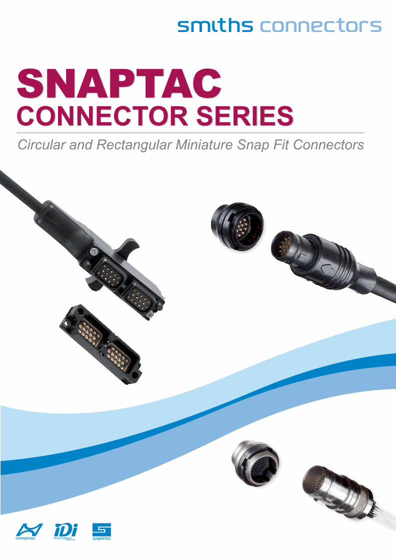
snaptacCONNECTOR SERIESCircular and Rectangular Miniature Snap Fit Connectors
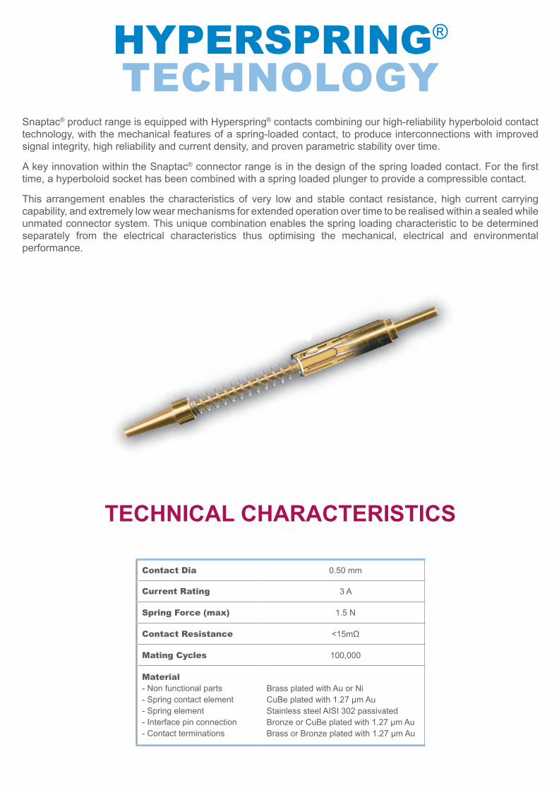
Hyperspring®
tecHnology Snaptac® product range is equipped with Hyperspring® contacts combining our high-reliability hyperboloid contact technology, with the mechanical features of a spring-loaded contact, to produce interconnections with improved signal integrity, high reliability and current density, and proven parametric stability over time.
A key innovation within the Snaptac® connector range is in the design of the spring loaded contact. For the first time, a hyperboloid socket has been combined with a spring loaded plunger to provide a compressible contact.
This arrangement enables the characteristics of very low and stable contact resistance, high current carrying capability, and extremely low wear mechanisms for extended operation over time to be realised within a sealed while unmated connector system. This unique combination enables the spring loading characteristic to be determined separately from the electrical characteristics thus optimising the mechanical, electrical and environmental performance.
TEChNICal ChaRaCTERISTICS
contact Dia 0.50 mm
current rating 3 A
spring Force (max) 1.5 N
contact resistance <15mΩ
Mating cycles 100,000
Material- Non functional parts- Spring contact element - Spring element - Interface pin connection - Contact terminations
Brass plated with Au or NiCuBe plated with 1.27 µm AuStainless steel AISI 302 passivatedBronze or CuBe plated with 1.27 µm AuBrass or Bronze plated with 1.27 µm Au
1
TablE Of CONTENTS
snaptac series SnapTac Miniature Connectors ......................................................................................2 Applicable documents ......................................................................................................3 Circular Connector Technical Characteristics .............................................................4
Ordering Information ............................................................................................. 6Available polarizations .......................................................................................... 7Pin Arrangement - View Mating Side .................................................................... 8Plug - Solder Cup Termination .............................................................................. 9Plug - Solder Cup Termination with Overmoulding and Cabling ........................... 9Plug - Solder Cup Termination with 90° Overmoulding and Cabling ..................... 9Receptacle - Straight Through Termination ........................................................ 10Receptacle - Solder Cup Termination ................................................................. 10Panel Cut-out ...................................................................................................... 10Extender - Solder Cup Termination ...................................................................... 11Extender with Overmoulding and Cabling ............................................................ 11Receptacle - Front Panel Mounting with Solder Cup Termination ....................... 12Panel Cut-out ...................................................................................................... 12Other Available options ....................................................................................... 13Accessories - Dust Cap....................................................................................... 16Cable Preparation ............................................................................................... 18
Rectangular Connector Technical Characteristics .....................................................19 Ordering Information ........................................................................................... 21
Plug - Solder Cup Termination ............................................................................ 22Plug with Overmoulding and Cabling .................................................................. 22Receptacle - Solder Cup Termination ................................................................. 23Receptacle - Straight Through Termination ......................................................... 23Panel Cut-out ...................................................................................................... 23Available polarizations for 12 and 21 ways ......................................................... 24Accessories - Dust Cap....................................................................................... 2530 Ways Plug - Solder Cup Termination ............................................................. 2630 Ways Plug with Overmoulding and Cabling ................................................... 2630 Ways Receptacle - Solder Cup Termination .................................................. 2730 Ways Receptacle - Straight Through Termination .......................................... 2730 Ways Plug - Front Panel Mount ..................................................................... 28
SNapTaC
2
SNapTaC MINIaTuRE CONNECTORSSnaptac® connectors provide a very reliable and robust connector system ideal for use in potentially dirty environments or where fast and easy mating and demating characteristics are required. Through the use of compressible contacts, potential mating and connectivity problems that can arise when the bores of conventional socket contacts become contaminated by the mud and detritus that may occur in everyday use are avoided. The easy to clean nature of the target and chisel blade contact mechanism, together with the sealed when unmated characteristic of both plug and receptacle, make this connector system ideal for harsh environments where reliability is paramount.
available geometriesSnaptac® connectors are available in both circular (7-, 13-, and 19-) and rectangular (12-, 21-, and 30-) way geometries.The SnapTac connector plugs are available in two versions, with and without over-moulding, following requests for both turn-key solutions and easy integration into existing designs.A 90° overmoulded version is also available for the circular connector. The receptacle offers straight through and solder cup termination styles. The locking mechanism is easy and fast: the circular connector range features a snap on locking, the 12 and 21 way rectangular connectors are push pull, the 30 way rectangular connector has a quick turn locking device.7, 13 and 19 way circular extenders, with and without overmoulding, are available for applications requiring in-line connection. Several hardware coding are available to avoid mismatching and to satisfy the customer technical needs as many non standard options are available. Please contact our sales office if you don’t find in the catalogue the version that meets your requirements.
Up to 10,000 mating cyclesTactical communication equipment must survive the rigours of hostile environments and withstand the damage of dust, sand, mud. The connectors used on both the handset and headset can be mated and unmated thousand of times during the equipment life. Snaptac® connectors ensure higher durability and superior performance through the use of the unique Hypertac hyperboloid
contact technology, offering shock and vibration immunity, low contact resistance, high current and voltage ratings, low mating forces, long life and low rate of wear.The HyperSpring® spring loaded contacts used inside the connectors cannot be damaged or bent from mishandling. Their inherent self cleaning wiping action removes surface contamination, thus ensuring that the connector can’t be damaged by the building up of surface films.
lighter and compactSnaptac® connectors combine robust environmental performance with compact size and light weight, which make them ideal for lightweight, compact, wearable EMI shielded electronic systems for applications including communication, identification / recognition, and other critical tasks.
Waterproof and eMi protectedSnaptac® connectors are IP67 sealed according to IEC529 when mated and unmated. They incorporate full line EMI shielding and provide for high robustness throughout their lifetime.
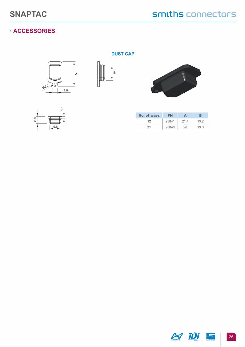
accessories - Dust caps Dust caps are available to protect the connector when unmated and to ensure full EMI shielding. The metal version is supplied in the same material of the connector (aluminium, stainless steel), the rubber version is available in fluoro-polymer rubber.Special flanges have been designed to facilitate the rectangular connector rear panel mounting.
Value added services Technical performance data hereby reported refer to Snaptac® connectors equipped with Hypertac cabling and overmoulding.Custom and value added solutions are provided for customers’ specific requirements including cabling, mechanical, instrumentation housing and testing. Custom solutions save valuable engineering and manufacturing time for customers and ensure the overall performance of the final product.
SNapTaC
3
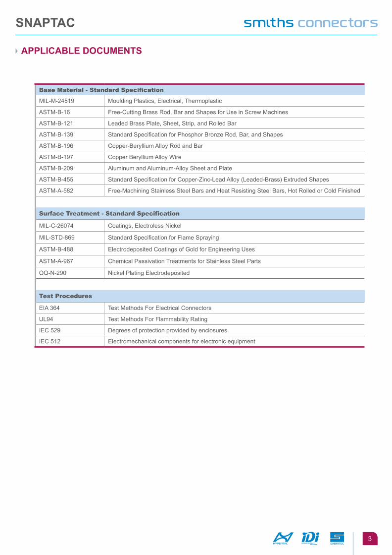
applICablE dOCuMENTS
Base Material - standard specification
MIL-M-24519 Moulding Plastics, Electrical, Thermoplastic
ASTM-B-16 Free-Cutting Brass Rod, Bar and Shapes for Use in Screw Machines
ASTM-B-121 Leaded Brass Plate, Sheet, Strip, and Rolled Bar
ASTM-B-139 Standard Specification for Phosphor Bronze Rod, Bar, and Shapes
ASTM-B-196 Copper-Beryllium Alloy Rod and Bar
ASTM-B-197 Copper Beryllium Alloy Wire
ASTM-B-209 Aluminum and Aluminum-Alloy Sheet and Plate
ASTM-B-455 Standard Specification for Copper-Zinc-Lead Alloy (Leaded-Brass) Extruded Shapes
ASTM-A-582 Free-Machining Stainless Steel Bars and Heat Resisting Steel Bars, Hot Rolled or Cold Finished
surface treatment - standard specification
MIL-C-26074 Coatings, Electroless Nickel
MIL-STD-869 Standard Specification for Flame Spraying
ASTM-B-488 Electrodeposited Coatings of Gold for Engineering Uses
ASTM-A-967 Chemical Passivation Treatments for Stainless Steel Parts
QQ-N-290 Nickel Plating Electrodeposited
test procedures
EIA 364 Test Methods For Electrical Connectors
UL94 Test Methods For Flammability Rating
IEC 529 Degrees of protection provided by enclosures
IEC 512 Electromechanical components for electronic equipment
SNapTaC
4
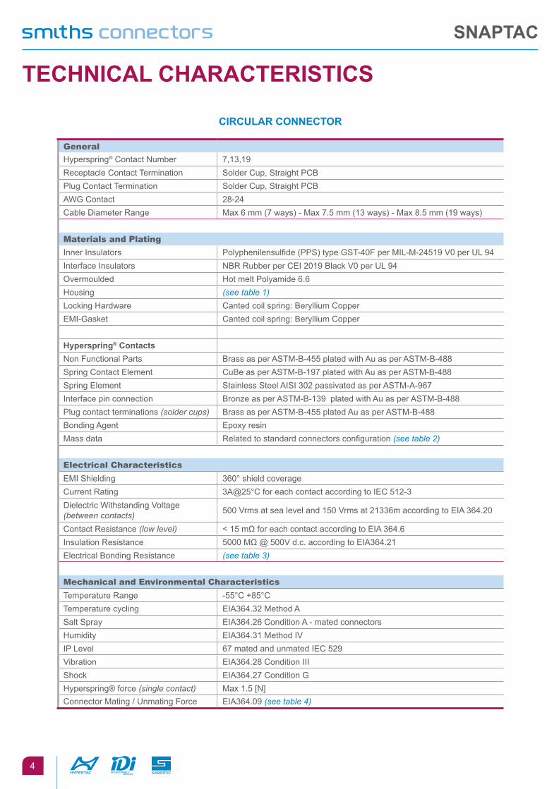
TEChNICal ChaRaCTERISTICS
CIRCulaR CONNECTOR
general
Hyperspring® Contact Number 7,13,19Receptacle Contact Termination Solder Cup, Straight PCBPlug Contact Termination Solder Cup, Straight PCBAWG Contact 28-24Cable Diameter Range Max 6 mm (7 ways) - Max 7.5 mm (13 ways) - Max 8.5 mm (19 ways)
Materials and plating
Inner Insulators Polyphenilensulfide (PPS) type GST-40F per MIL-M-24519 V0 per UL 94Interface Insulators NBR Rubber per CEI 2019 Black V0 per UL 94Overmoulded Hot melt Polyamide 6.6Housing (see table 1)Locking Hardware Canted coil spring: Beryllium CopperEMI-Gasket Canted coil spring: Beryllium Copper
hyperspring® ContactsNon Functional Parts Brass as per ASTM-B-455 plated with Au as per ASTM-B-488Spring Contact Element CuBe as per ASTM-B-197 plated with Au as per ASTM-B-488Spring Element Stainless Steel AISI 302 passivated as per ASTM-A-967Interface pin connection Bronze as per ASTM-B-139 plated with Au as per ASTM-B-488Plug contact terminations (solder cups) Brass as per ASTM-B-455 plated Au as per ASTM-B-488Bonding Agent Epoxy resinMass data Related to standard connectors configuration (see table 2)
electrical characteristics
EMI Shielding 360° shield coverageCurrent Rating 3A@25°C for each contact according to IEC 512-3Dielectric Withstanding Voltage (between contacts) 500 Vrms at sea level and 150 Vrms at 21336m according to EIA 364.20
Contact Resistance (low level) < 15 mΩ for each contact according to EIA 364.6Insulation Resistance 5000 MΩ @ 500V d.c. according to EIA364.21Electrical Bonding Resistance (see table 3)
Mechanical and environmental characteristics
Temperature Range -55°C +85°CTemperature cycling EIA364.32 Method ASalt Spray EIA364.26 Condition A - mated connectorsHumidity EIA364.31 Method IVIP Level 67 mated and unmated IEC 529Vibration EIA364.28 Condition III Shock EIA364.27 Condition GHyperspring® force (single contact) Max 1.5 [N]Connector Mating / Unmating Force EIA364.09 (see table 4)
SNapTaC
5
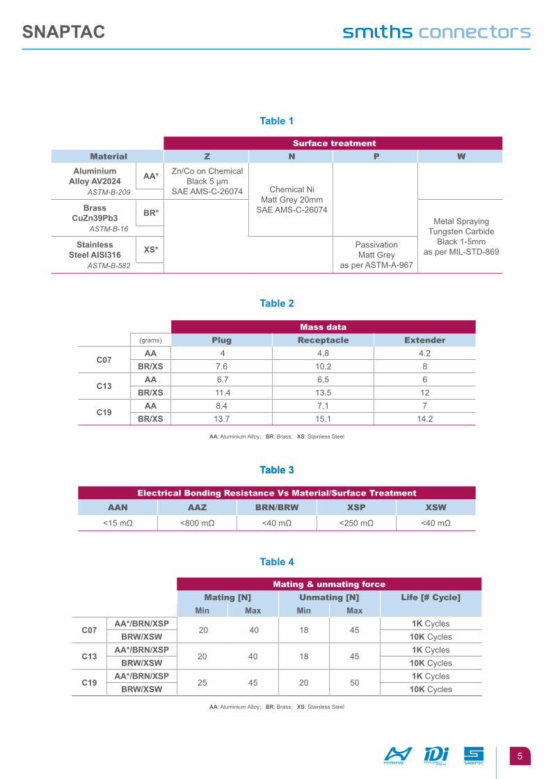
Table 1
Table 2
Table 3
Table 4
Table 3
surface treatment
Material Z n p W
aluminiumalloy aV2024 aa* Zn/Co on Chemical
Black 5 µmSAE AMS-C-26074 Chemical Ni
Matt Grey 20mmSAE AMS-C-26074
ASTM-B-209
brassCuZn39pb3 bR*
Metal SprayingTungsten Carbide
Black 1-5mmas per MIL-STD-869
ASTM-B-16
StainlessSteel aISI316 XS* Passivation
Matt Greyas per ASTM-A-967ASTM-B-582
Mass data
(grams) plug receptacle extender
C07aa 4 4.8 4.2
bR/XS 7.6 10.2 8
C13aa 6.7 6.5 6
bR/XS 11.4 13.5 12
C19aa 8.4 7.1 7
bR/XS 13.7 15.1 14.2
aa: Aluminium Alloy; bR: Brass; XS: Stainless Steel
Mating & unmating force
Mating [n] Unmating [n] life [# cycle]
Min Max Min Max
C07aa*/bRN/XSp
20 40 18 451K Cycles
bRW/XSW 10K Cycles
C13aa*/bRN/XSp
20 40 18 451K Cycles
bRW/XSW 10K Cycles
C19aa*/bRN/XSp
25 45 20 501K Cycles
bRW/XSW 10K Cycles
aa: Aluminium Alloy; bR: Brass; XS: Stainless Steel
electrical Bonding resistance Vs Material/surface treatment
aan aaZ Brn/BrW xsp xsW
<15 mΩ <800 mΩ <40 mΩ <250 mΩ <40 mΩ
SNapTaC
6
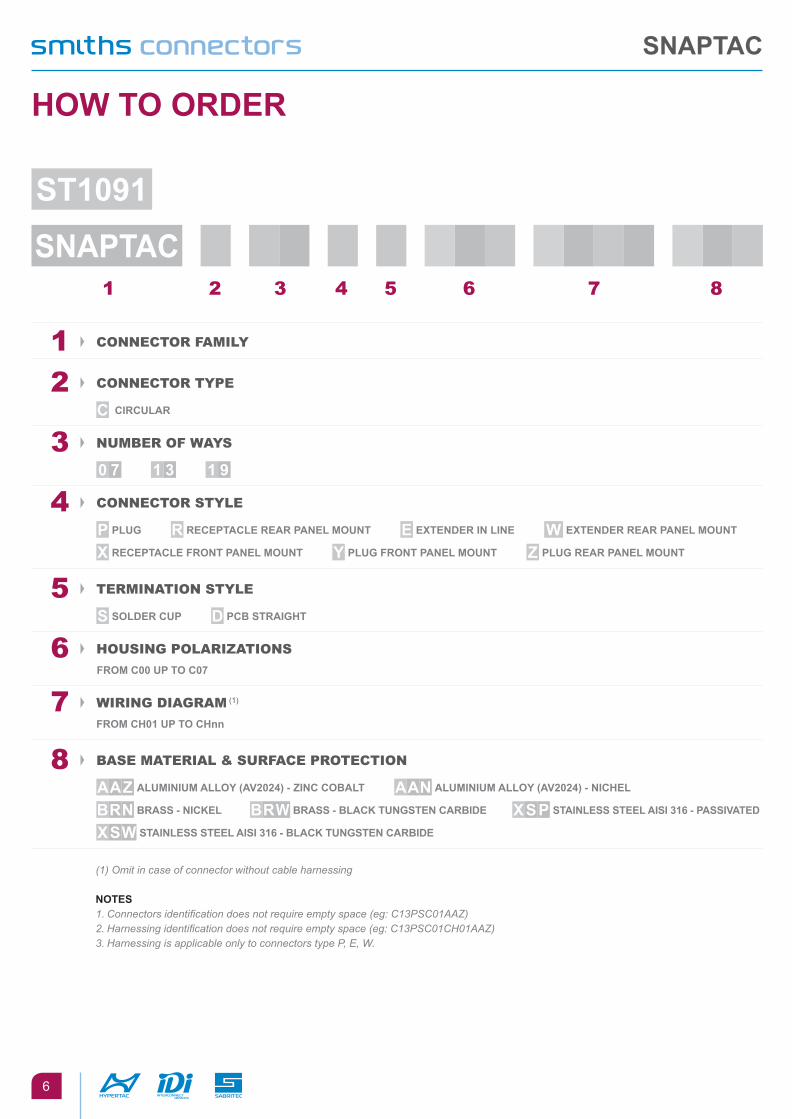
1 2 3 4 5 6 7 8
1 connector FaMily
2 connector type
C CIRCulaR
3 nUMBer oF Ways
0 7 1 3 1 9
4 connector style
p plug R RECEpTaClE REaR paNEl MOuNT E EXTENdER IN lINE W EXTENdER REaR paNEl MOuNT
X RECEpTaClE fRONT paNEl MOuNT Y plug fRONT paNEl MOuNT Z plug REaR paNEl MOuNT
5 terMination style
S SOldER Cup d pCb STRaIghT
6 HoUsing polariZations
fROM C00 up TO C07
7 Wiring DiagraM (1)
fROM Ch01 up TO Chnn
8 Base Material & sUrFace protection
aaZ aluMINIuM allOY (aV2024) - ZINC CObalT aaN aluMINIuM allOY (aV2024) - NIChEl
bRN bRaSS - NICKEl bRW bRaSS - blaCK TuNgSTEN CaRbIdE XSp STaINlESS STEEl aISI 316 - paSSIVaTEd
XSW STaINlESS STEEl aISI 316 - blaCK TuNgSTEN CaRbIdE
(1) Omit in case of connector without cable harnessing
NOTES1.Connectorsidentificationdoesnotrequireemptyspace(eg:C13PSC01AAZ)2.Harnessingidentificationdoesnotrequireemptyspace(eg:C13PSC01CH01AAZ)3.HarnessingisapplicableonlytoconnectorstypeP,E,W.
hOW TO ORdER
ST1091
SNapTaC
SNapTaC
7
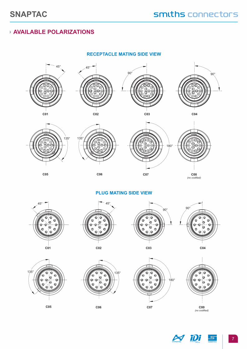
aVaIlablE pOlaRIZaTIONS
RECEpTaClE MaTINg SIdE VIEW
plug MaTINg SIdE VIEW
45° 45°
90° 90°
C01 C02 C04C03
135°
C05
135°
C06
180°
C07 C00(no codified)
45° 45°
90° 90°
C01 C02 C03 C04
135°
C05
135°
C06 C07 C00(no codified)
180°
SNapTaC
8
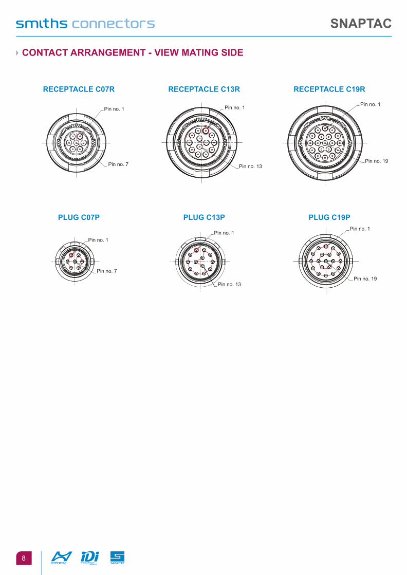
CONTaCT aRRaNgEMENT - VIEW MaTINg SIdE
RECEpTaClE C07R
plug C07p
RECEpTaClE C13R
plug C13p
RECEpTaClE C19R
plug C19p
Pin no. 1 Pin no. 1 Pin no. 1
Pin no. 7 Pin no. 13 Pin no. 19
Pin no. 1 Pin no. 1
Pin no. 1
Pin no. 7
Pin no. 13 Pin no. 19
SNapTaC
9
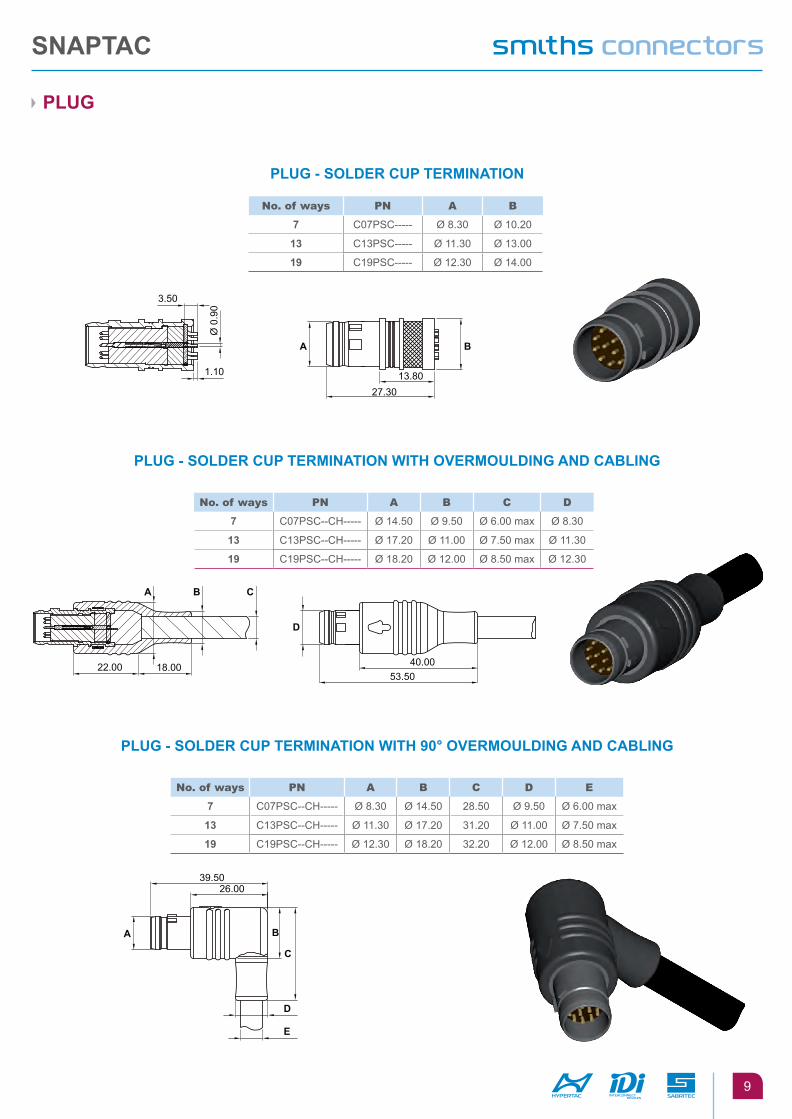
plug
plug - SOldER Cup TERMINaTION
plug - SOldER Cup TERMINaTION WITh OVERMOuldINg aNd CablINg
plug - SOldER Cup TERMINaTION WITh 90° OVERMOuldINg aNd CablINg
no. of ways pn a B c D
7 C07PSC--CH----- Ø 14.50 Ø 9.50 Ø 6.00 max Ø 8.30
13 C13PSC--CH----- Ø 17.20 Ø 11.00 Ø 7.50 max Ø 11.30
19 C19PSC--CH----- Ø 18.20 Ø 12.00 Ø 8.50 max Ø 12.30
no. of ways pn a B c D e
7 C07PSC--CH----- Ø 8.30 Ø 14.50 28.50 Ø 9.50 Ø 6.00 max
13 C13PSC--CH----- Ø 11.30 Ø 17.20 31.20 Ø 11.00 Ø 7.50 max
19 C19PSC--CH----- Ø 12.30 Ø 18.20 32.20 Ø 12.00 Ø 8.50 max
40.0053.50
22.00 18.00
A B C
D
26.0039.50
A B
C
D
E
13.8027.30
1.10
3.50
Ø 0
.90
A B
no. of ways pn a B
7 C07PSC----- Ø 8.30 Ø 10.20
13 C13PSC----- Ø 11.30 Ø 13.00
19 C19PSC----- Ø 12.30 Ø 14.00
SNapTaC
10
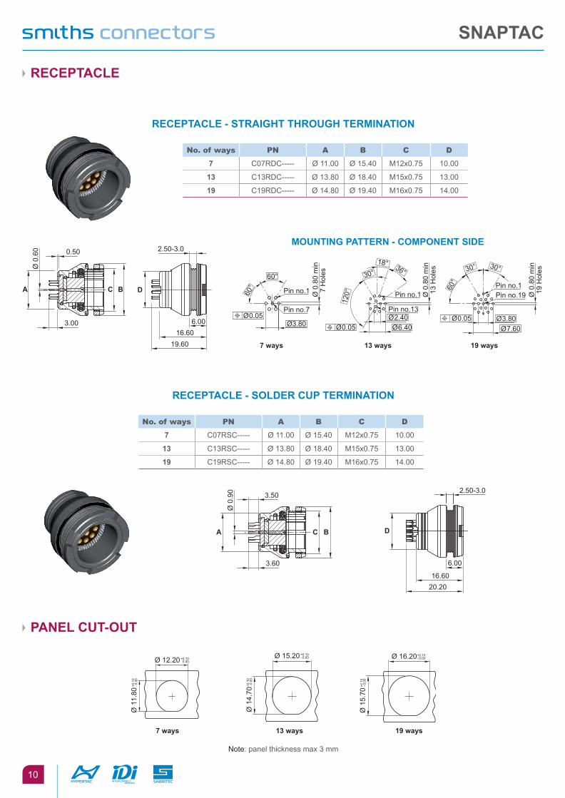
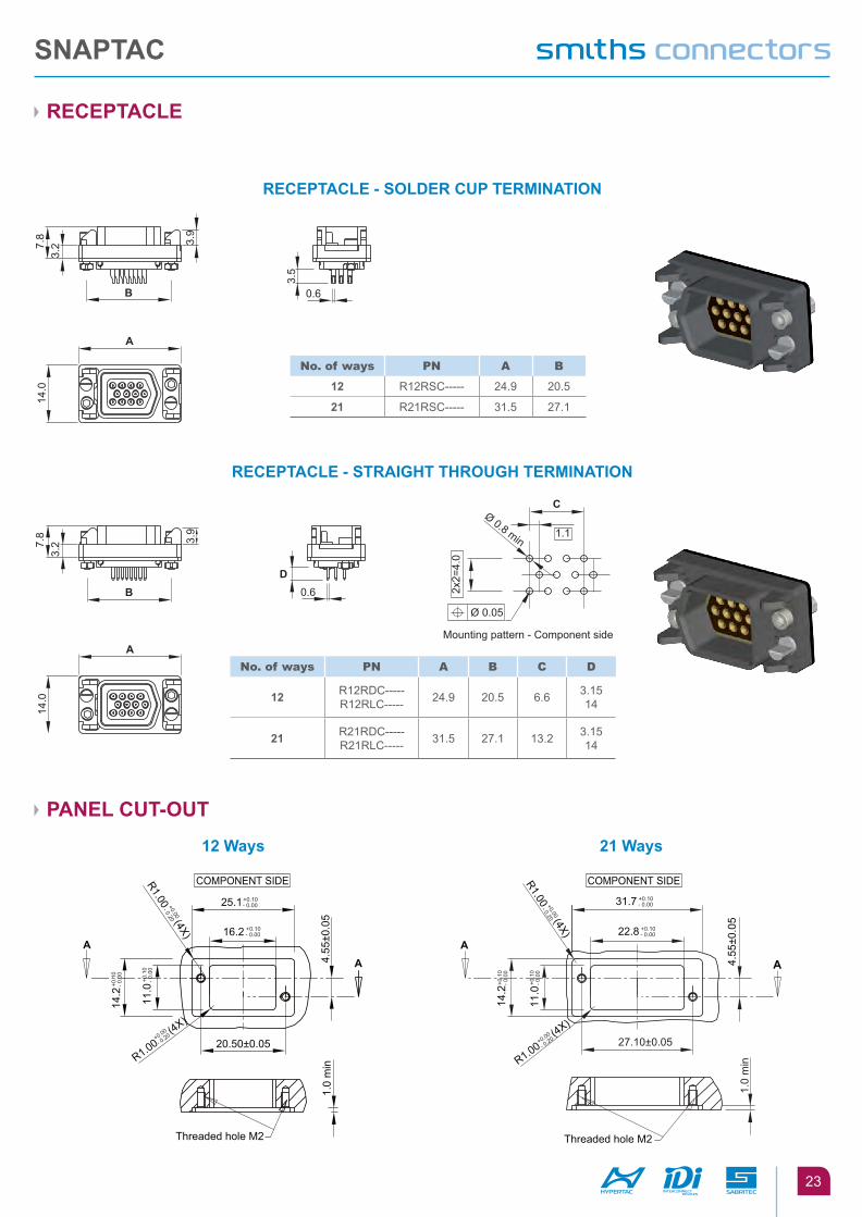
RECEpTaClE
paNEl CuT-OuT
RECEpTaClE - STRaIghT ThROugh TERMINaTION
RECEpTaClE - SOldER Cup TERMINaTION
MOuNTINg paTTERN - COMpONENT SIdE
3.00
0.50 2.50-3.0
Ø 0
.60
6.0016.60
19.60
BCA D
no. of ways pn a B c D
7 C07RDC----- Ø 11.00 Ø 15.40 M12x0.75 10.00
13 C13RDC----- Ø 13.80 Ø 18.40 M15x0.75 13.00
19 C19RDC----- Ø 14.80 Ø 19.40 M16x0.75 14.00
no. of ways pn a B c D
7 C07RSC----- Ø 11.00 Ø 15.40 M12x0.75 10.00
13 C13RSC----- Ø 13.80 Ø 18.40 M15x0.75 13.00
19 C19RSC----- Ø 14.80 Ø 19.40 M16x0.75 14.00
60°
7 ways
Ø 0.05
Pin no.1 Pin no.1 Pin no.1 Pin no.19
Pin no.7 Pin no.13 7
Hol
es
60° 60
°
Ø 0
.80
min
13 H
oles
Ø 0
.80
min
19 H
oles
Ø 0
.80
min
Ø 3.80
13 ways
Ø 0.05 Ø 6.40 Ø 2.40
19 ways
Ø 0.05 Ø 7.60
Ø 3.80
36°18°
30° 30° 30°
120°
3.60
3.502.50-3.0
6.00
16.6020.20
Ø 0
.90
A C B D
7 ways 13 ways 19 ways
Ø 12.20+0.10- 0.00
Ø 1
1.80
+0.1
0- 0
.00
Ø 1
4.70
+0.1
0- 0
.00
Ø 15.20+0.10- 0.00
Ø 1
5.70
+0.1
0- 0
.00
Ø 16.20+0.10- 0.00
Note: panel thickness max 3 mm
SNapTaC
11
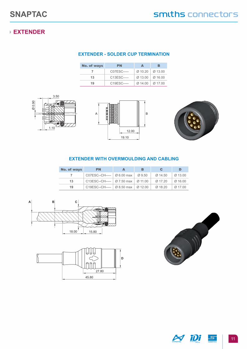
EXTENdER
EXTENdER - SOldER Cup TERMINaTION
EXTENdER WITh OVERMOuldINg aNd CablINg
no. of ways pn a B
7 C07ESC----- Ø 10.20 Ø 13.00
13 C13ESC----- Ø 13.00 Ø 16.00
19 C19ESC----- Ø 14.00 Ø 17.00
no. of ways pn a B c D
7 C07ESC--CH----- Ø 6.00 max Ø 9.50 Ø 14.50 Ø 13.00
13 C13ESC--CH----- Ø 7.50 max Ø 11.00 Ø 17.20 Ø 16.00
19 C19ESC--CH----- Ø 8.50 max Ø 12.00 Ø 18.20 Ø 17.00
A
12.00
19.10
1.10
3.50
Ø 0
.90
B
27.80
45.80
15.8018.00
A B C
D
SNapTaC
12
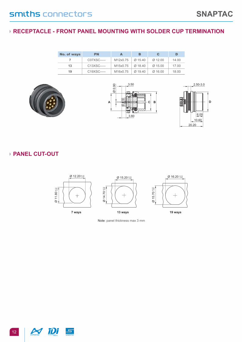
RECEpTaClE - fRONT paNEl MOuNTINg WITh SOldER Cup TERMINaTION
paNEl CuT-OuT
no. of ways pn a B c D
7 C07XSC----- M12x0.75 Ø 15.40 Ø 12.00 14.00
13 C13XSC----- M15x0.75 Ø 18.40 Ø 15.00 17.00
19 C19XSC----- M16x0.75 Ø 19.40 Ø 16.00 18.00
3.60
3.50 2.50-3.0
6.00
20.2010.60
Ø 0
.90
A C B D
7 ways 13 ways 19 ways
Ø 1
1.80
+0.1
0- 0
.00
Ø 1
4.70
+0.1
0- 0
.00
Ø 1
5.70
+0.1
0- 0
.00
Ø 12.20+0.10- 0.00 Ø 15.20+0.10
- 0.00Ø 16.20 +0.10
- 0.00
Note: panel thickness max 3 mm
SNapTaC
13
Panel cut-out27.30
13.80
3.50
1.10
9.80
13.0
0
M12
x0.7
53.50
Ø 1
1.80
+0.1
0- 0
.00
Ø 12.20 +0.10- 0.00
Ø0.
90
Ø 8
.30
Ø 1
5.40
M15
x0.7
5
3.50
1.10
7.806.0027.30
12.0
0
2.50-3.0
Ø 0
.90
Ø 1
3.00
Ø 1
8.40
Ø 1
1.30
Panel cut-outpanel thickness max 3 mm
Ø 1
4.70
+0.1
0- 0
.00
Ø 15.20+0.10- 0.00
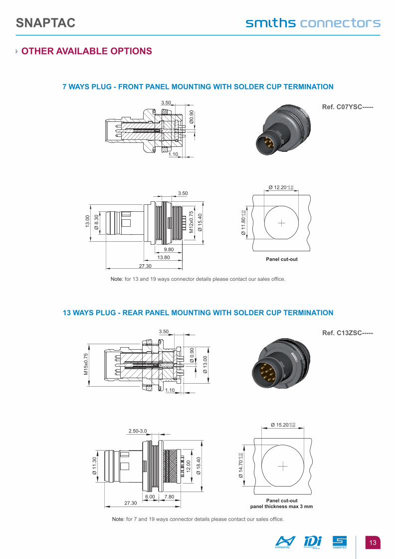
OThER aVaIlablE OpTIONS
Note: for 13 and 19 ways connector details please contact our sales office.
Note: for 7 and 19 ways connector details please contact our sales office.
7 WaYS plug - fRONT paNEl MOuNTINg WITh SOldER Cup TERMINaTION
13 WaYS plug - REaR paNEl MOuNTINg WITh SOldER Cup TERMINaTION
Ref. C07YSC-----
Ref. C13ZSC-----
SNapTaC
14
15.80
54.8013.50 6.00
M15
x0.7
5
2.50-3.0
18.00
Panel cut-outpanel thickness max 3 mm
Ø 1
7.20
Ø 1
1.00
Ø 7
.50
max
Ø 1
8.40
Ø 1
1.30
Ø 1
4.70
+0.1
0- 0
.00
Ø 15.20+0.10- 0.00
19.10
3.50
1.10
M16
x0.7
5
12.00
6.00
2.50-3.0
18.0
0Ø
0.9
0
Ø 1
9.40
Ø 1
9.40
Ø 1
4.00
Panel cut-outpanel thickness max 3 mm
Ø 1
5.70
+0.1
0- 0
.00
Ø 16.20+0.10- 0.00
OThER aVaIlablE OpTIONS
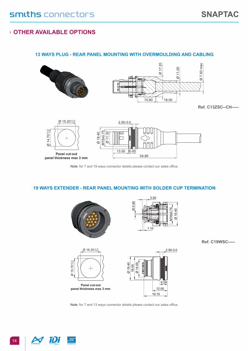
Note: for 7 and 19 ways connector details please contact our sales office.
Note: for 7 and 13 ways connector details please contact our sales office.
13 WaYS plug - REaR paNEl MOuNTINg WITh OVERMOuldINg aNd CablINg
19 WaYS EXTENdER - REaR paNEl MOuNTINg WITh SOldER Cup TERMINaTION
Ref. C13ZSC--Ch-----
Ref. C19WSC-----
SNapTaC
15
15.8018.00
27.80
2.50-3.0
M16
x0.7
5
6.00
45.80
Ø 8
.50
max
Ø 1
2.00
Ø 1
8.20
Ø 1
9.40
Panel cut-outpanel thickness max 3 mm
Ø 1
5.70
+0.1
0- 0
.00
Ø 16.20+0.10- 0.00
OThER aVaIlablE OpTIONS
Note: for 7 and 13 ways connector details please contact our sales office.
19 WaYS EXTENdER - REaR paNEl MOuNTINg WITh OVERMOuldINg aNd CablINg
Ref. C19WSC--Ch-----
SNapTaC
16
1 2 3 4 5 6
1 connector FaMily
2 connector type
C CIRCulaR
3 nUMBer oF Ways
0 7 1 3 1 9
4 DUst cap type
Cp duST Cap fOR plug CR duST Cap fOR RECEpTaClE
5 DUst cap Version
ME T METallIC Cap Rub RubbER Cap
6 Base Material & sUrFace protection
aaZ* aluMINIuM allOY (aV2024) - ZINC CObalT aaN*
aluMINIuM allOY (aV2024) - NIChEl
bRN* bRaSS - NICKEl bRW*
bRaSS - blaCK TuNgSTEN CaRbIdE XSp* STaINlESS STEEl aISI 316 - paSSIVaTEd
XSW* STaINlESS STEEl aISI 316 - blaCK TuNgSTEN CaRbIdE f p R **
fluORO pOlYMER RubbER
*OnlyforMET **OnlyforRUB
hOW TO ORdER
ST1091
SNapTaC
aCCESSORIES - duST Cap
SNapTaC
17
duST Cap
METal VERSION fOR RECEpTaClE
METal VERSION fOR plug
RubbER VERSION fOR RECEpTaClE
RubbER VERSION fOR plug
no. of ways pn a7 C07CRMET--- Ø 15.00
13 C13CRMET--- Ø 17.5019 C19CRMET--- Ø 18.50
no. of ways pn a7 C07CPMET--- Ø 15.00
13 C13CPMET--- Ø 17.5019 C19CPMET--- Ø 18.50
no. of ways pn a B c7 C07CRRUBFPR 23.00 Ø 9.00 Ø 13.0013 C13CRRUBFPR 26.00 Ø 12.00 Ø 16.0019 C19CRRUBFPR 27.00 Ø 13.00 Ø 17.00
no. of ways pn a B c7 C07CPRUBFPR 11.70 13.00 20.5013 C13CPRUBFPR 14.70 16.50 22.2519 C19CPRUBFPR 15.70 17.00 22.50
10.5
0
23.5
0200
Ø 1
.00
A
4.00
6.00
Ø 2
.40
A
B
C
A
B
C
Ø2.
4
A
200
Ø 1
.5
33.7
5
SNapTaC
18
CablE pREpaRaTION
See below the stripping lengths for braid shield (A) and single wire (B & C).
See below the knurled area for braid shield connection.
EMI/EMC pROTECTIONPlug (ref. P), extender in line (ref. E) and extender rear panel mounting (ref. W) of this specification are designed to be supplied with assembled cables.The electrical continuity between metal shell and cable shield is granted by a specific metallic coil spring for cable braid as showed in the picture.
plug (ref p) extender (ref e)
a 15 13
b 10 10
C 3.5 3.5
connector size order reference
C07 M1035
C13 M1036
C19 M1036
“Metallic coil spring”
4.80 4.80
A
B
C
SNapTaC
19
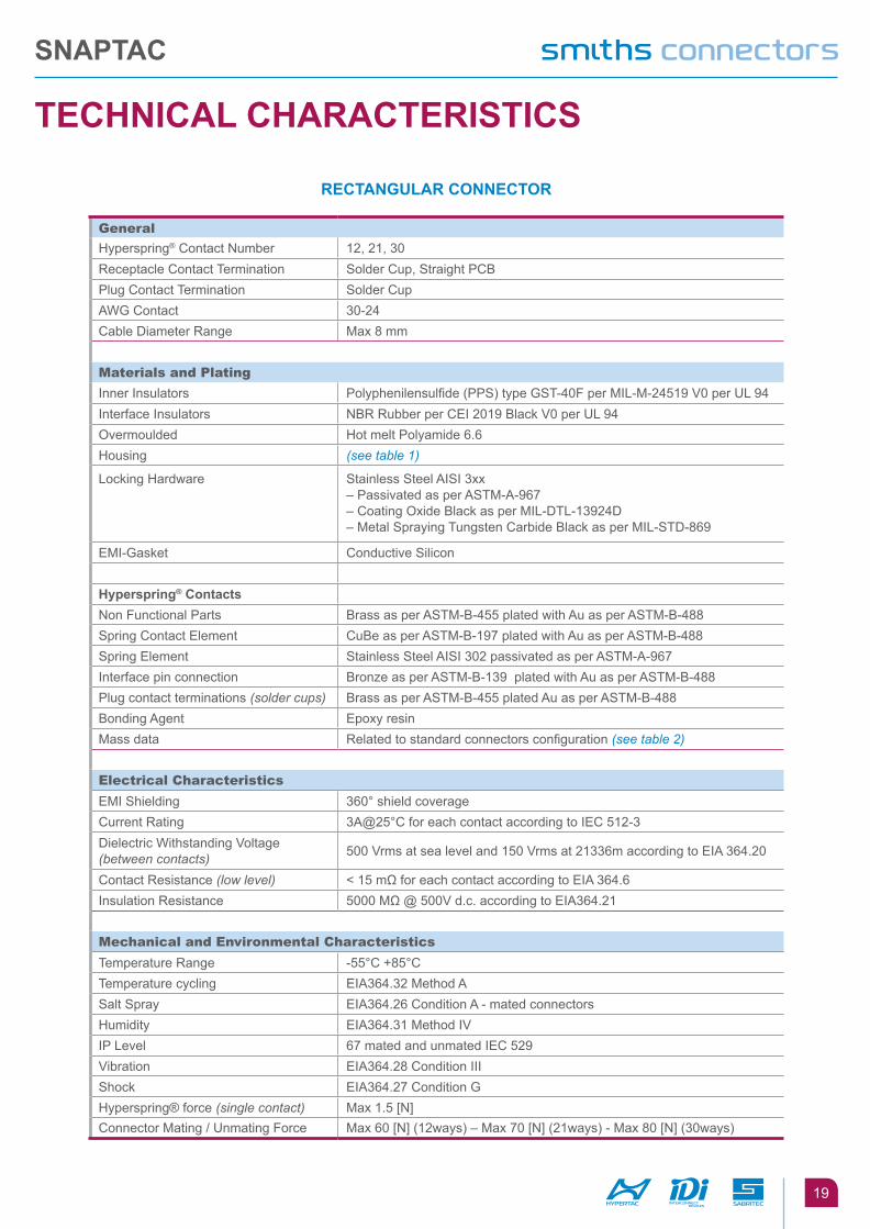
TEChNICal ChaRaCTERISTICS
RECTaNgulaR CONNECTOR
general
Hyperspring® Contact Number 12, 21, 30Receptacle Contact Termination Solder Cup, Straight PCBPlug Contact Termination Solder CupAWG Contact 30-24Cable Diameter Range Max 8 mm
Materials and plating
Inner Insulators Polyphenilensulfide (PPS) type GST-40F per MIL-M-24519 V0 per UL 94Interface Insulators NBR Rubber per CEI 2019 Black V0 per UL 94Overmoulded Hot melt Polyamide 6.6Housing (see table 1)
Locking Hardware Stainless Steel AISI 3xx– Passivated as per ASTM-A-967– Coating Oxide Black as per MIL-DTL-13924D– Metal Spraying Tungsten Carbide Black as per MIL-STD-869
EMI-Gasket Conductive Silicon
hyperspring® ContactsNon Functional Parts Brass as per ASTM-B-455 plated with Au as per ASTM-B-488Spring Contact Element CuBe as per ASTM-B-197 plated with Au as per ASTM-B-488Spring Element Stainless Steel AISI 302 passivated as per ASTM-A-967Interface pin connection Bronze as per ASTM-B-139 plated with Au as per ASTM-B-488Plug contact terminations (solder cups) Brass as per ASTM-B-455 plated Au as per ASTM-B-488Bonding Agent Epoxy resinMass data Related to standard connectors configuration (see table 2)
electrical characteristics
EMI Shielding 360° shield coverageCurrent Rating 3A@25°C for each contact according to IEC 512-3Dielectric Withstanding Voltage (between contacts) 500 Vrms at sea level and 150 Vrms at 21336m according to EIA 364.20
Contact Resistance (low level) < 15 mΩ for each contact according to EIA 364.6Insulation Resistance 5000 MΩ @ 500V d.c. according to EIA364.21
Mechanical and environmental characteristics
Temperature Range -55°C +85°CTemperature cycling EIA364.32 Method ASalt Spray EIA364.26 Condition A - mated connectorsHumidity EIA364.31 Method IVIP Level 67 mated and unmated IEC 529Vibration EIA364.28 Condition III Shock EIA364.27 Condition GHyperspring® force (single contact) Max 1.5 [N]Connector Mating / Unmating Force Max 60 [N] (12ways) – Max 70 [N] (21ways) - Max 80 [N] (30ways)
SNapTaC
20
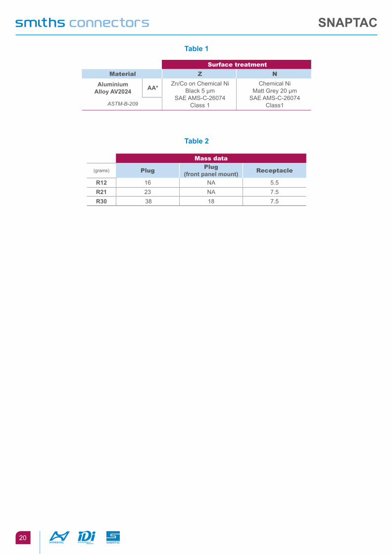
Table 1
Table 2
surface treatment
Material Z n
aluminiumalloy aV2024 aa*
Zn/Co on Chemical NiBlack 5 µm
SAE AMS-C-26074Class 1
Chemical NiMatt Grey 20 µm
SAE AMS-C-26074Class1ASTM-B-209
Mass data
(grams) plugplug
(front panel mount) receptacle
R12 16 NA 5.5R21 23 NA 7.5R30 38 18 7.5
SNapTaC
21
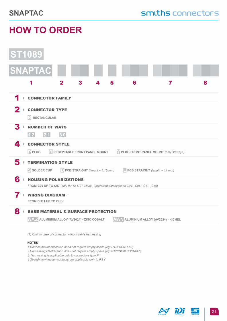
1 2 3 4 5 6 7 8
1 connector FaMily
2 connector type
R RECTaNgulaR
3 nUMBer oF Ways
1 2 2 1 3 0
4 connector style
p plug R RECEpTaClE fRONT paNEl MOuNT Y plug fRONT paNEl MOuNT (only30ways)
5 terMination style
S SOldER Cup d pCb STRaIghT (lenght = 3.15 mm) l pCb STRaIghT (lenght = 14 mm)
6 HoUsing polariZations
fROM C00 up TO C07 (onlyfor12&21ways)-(preferredpolarizationsC01-C06-C11-C16)
7 Wiring DiagraM (1)
fROM Ch01 up TO Chnn
8 Base Material & sUrFace protection
aaZ aluMINIuM allOY (aV2024) - ZINC CObalT aaN aluMINIuM allOY (aV2024) - NIChEl
(1) Omit in case of connector without cable harnessing
NOTES1Connectorsidentificationdoesnotrequireemptyspace(eg:R12PSC01AAZ)2Harnessingidentificationdoesnotrequireemptyspace(eg:R12PSC01CH01AAZ)3 HarnessingisapplicableonlytoconnectorstypeP4StraightterminationcontactsareapplicableonlytoR&Y
hOW TO ORdER
ST1089
SNapTaC
SNapTaC
22
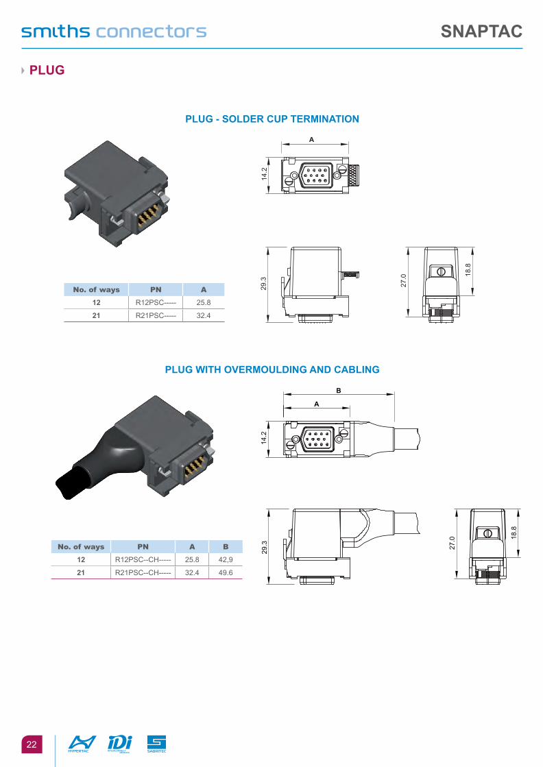
plug
plug - SOldER Cup TERMINaTION
plug WITh OVERMOuldINg aNd CablINg
no. of ways pn a
12 R12PSC----- 25.8
21 R21PSC----- 32.4
18.8
27.0
14.2
A
29.3
SCALE 1:1
no. of ways pn a B
12 R12PSC--CH----- 25.8 42,9
21 R21PSC--CH----- 32.4 49.6
18.8
27.0
14.2
A
29.3
B
SCALE 1:1
SNapTaC
23
RECEpTaClE
RECEpTaClE - SOldER Cup TERMINaTION
RECEpTaClE - STRaIghT ThROugh TERMINaTION
12 Ways 21 Ways
SCALE 1:1
14.0
A
B
3.9
7.8
3.2
3.5
0.6
no. of ways pn a B
12 R12RSC----- 24.9 20.5
21 R21RSC----- 31.5 27.1
14.0
A
B
3.9
7.8
3.2
D0.6
Mounting pattern - Component side
Ø 0.8 min
C
Ø 0.05
2x2=
4.0
1.1
no. of ways pn a B c D
12 R12RDC-----R12RLC----- 24.9 20.5 6.6 3.15
14
21 R21RDC-----R21RLC----- 31.5 27.1 13.2 3.15
14
paNEl CuT-OuT
AA
1.0
min
20.50±0.05
4.55
±0.0
5
COMPONENT SIDE
Threaded hole M2 Threaded hole M2
COMPONENT SIDE
14.2
+0.1
0- 0
.00
11.0
+0.1
0- 0
.00
25.1+0.10- 0.00
16.2 +0.10- 0.00
R1.00 +0.00
- 0.20 (4X)
R1.00+0.00
- 0.20(4
X)
1.0
min
27.10±0.05
4.55
±0.0
5
R1.00 +0.00
- 0.20 (4X)
31.7 +0.10- 0.00
22.8 +0.10- 0.00
14.2
+0.1
0- 0
.00
11.0
+0.1
0- 0
.00
A
A
R1.00+0.00
- 0.20
(4X)
SNapTaC
24
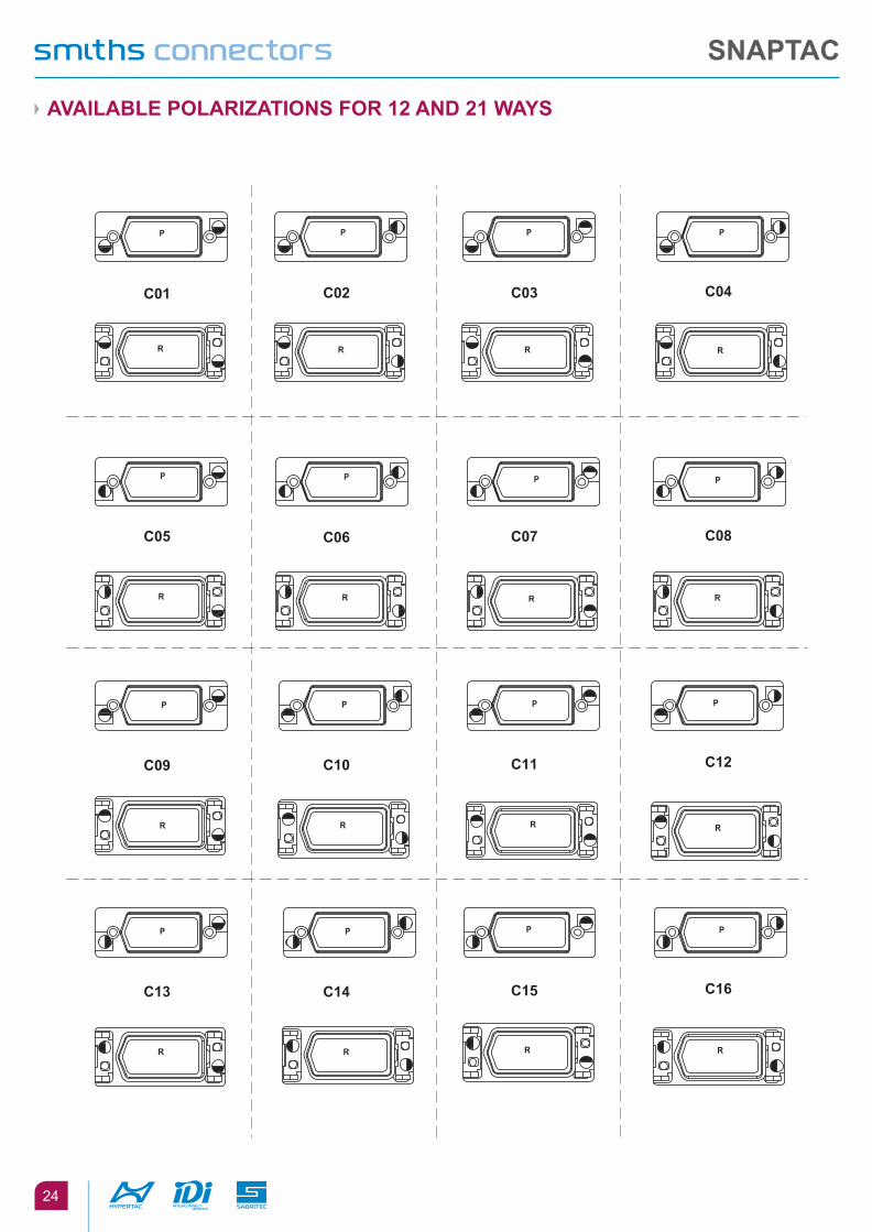
aVaIlablE pOlaRIZaTIONS fOR 12 aNd 21 WaYS
C01
P
R
C02
P
R
C03
P
R
C04
P
R
C05
P
R
C06
P
R
C07
P
R
C08
P
R
C09
P
R
C10
P
R
C11
P
R
C12
P
R
C13
P
R
C14
P
R
C15
P
R
C16
P
R
SNapTaC
25
aCCESSORIES
duST Cap1.
5
6.0
A
4.0
9.6
B
Ø 2.0
no. of ways pn a B
12 23841 21.4 13.2
21 23840 28 19.8
SNapTaC
26
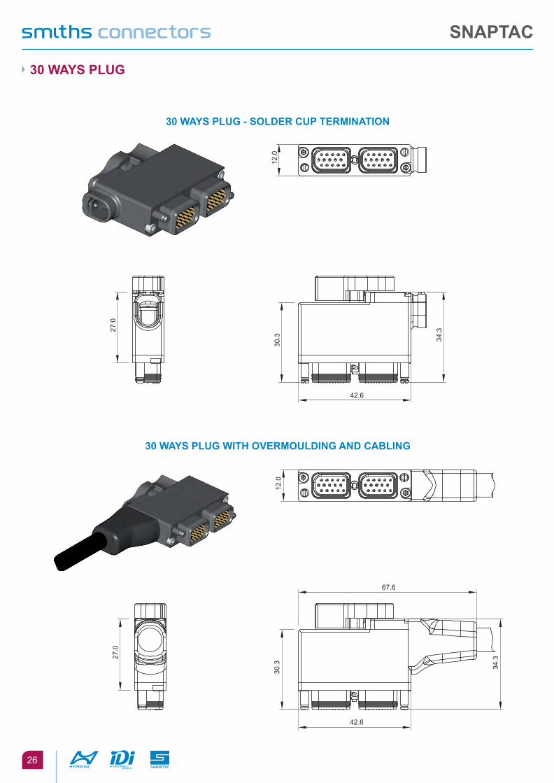
30 WaYS plug
30 WaYS plug - SOldER Cup TERMINaTION
30 WaYS plug WITh OVERMOuldINg aNd CablINg
12.0
30.3
42.6
34.327
.0
12.0
30.3
42.6
34.327
.0
67.6
SNapTaC
27
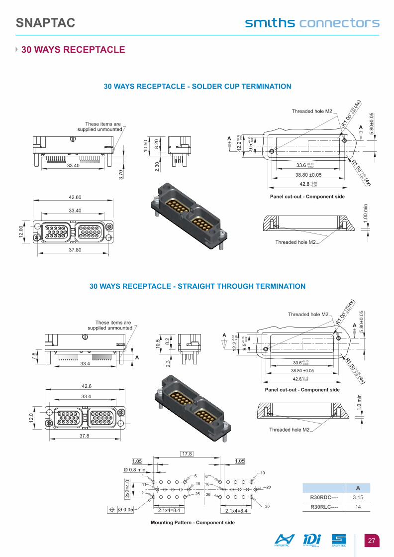
30 WaYS RECEpTaClE
30 WaYS RECEpTaClE - SOldER Cup TERMINaTION
30 WaYS RECEpTaClE - STRaIghT ThROugh TERMINaTION
A
A
12.0
0
42.60
33.40
10.5
0
8.20
2.30
37.80
3.70
33.40
1.00
min
38.80 ±0.05
5.80
±0.0
5
These items are supplied unmounted
Threaded hole M2
Threaded hole M2
12.2
+0.1
0- 0
.00
9.5
+0.1
0- 0
.00
33.6 +0.10- 0.00
42.8 +0.10- 0.00
R1.0
0+
0.00
- 0.2
0(4
x)
R1.00 + 0.00
- 0.20 (4x)
Panel cut-out - Component side
A
12.0
42.6
33.4
10.5 8.
22.
3
37.8
2x2=
4.0
2.1x4=8.4 2.1x4=8.4
7.8
A
33.4
1.0517.8
1.0
min
38.80 ±0.05
5.80
±0.0
5
Mounting Pattern - Component side
Panel cut-out - Component side
These items are supplied unmounted
10
20
30
5
15
25
6
16
26
1
11
21
Threaded hole M2
Threaded hole M2
A
12.2
+0.1
0- 0
.00
9.5+0
.10
- 0.0
0
33.6+0.10- 0.00
42.8+0.10- 0.00
R1.0
0+ 0
.00
- 0.2
0(4
x)
R1.00 + 0.00
- 0.20 (4x)
Ø 0.8 min
Ø 0.05
1.05
a
R30RdC---- 3.15
R30RlC---- 14
SNapTaC
28
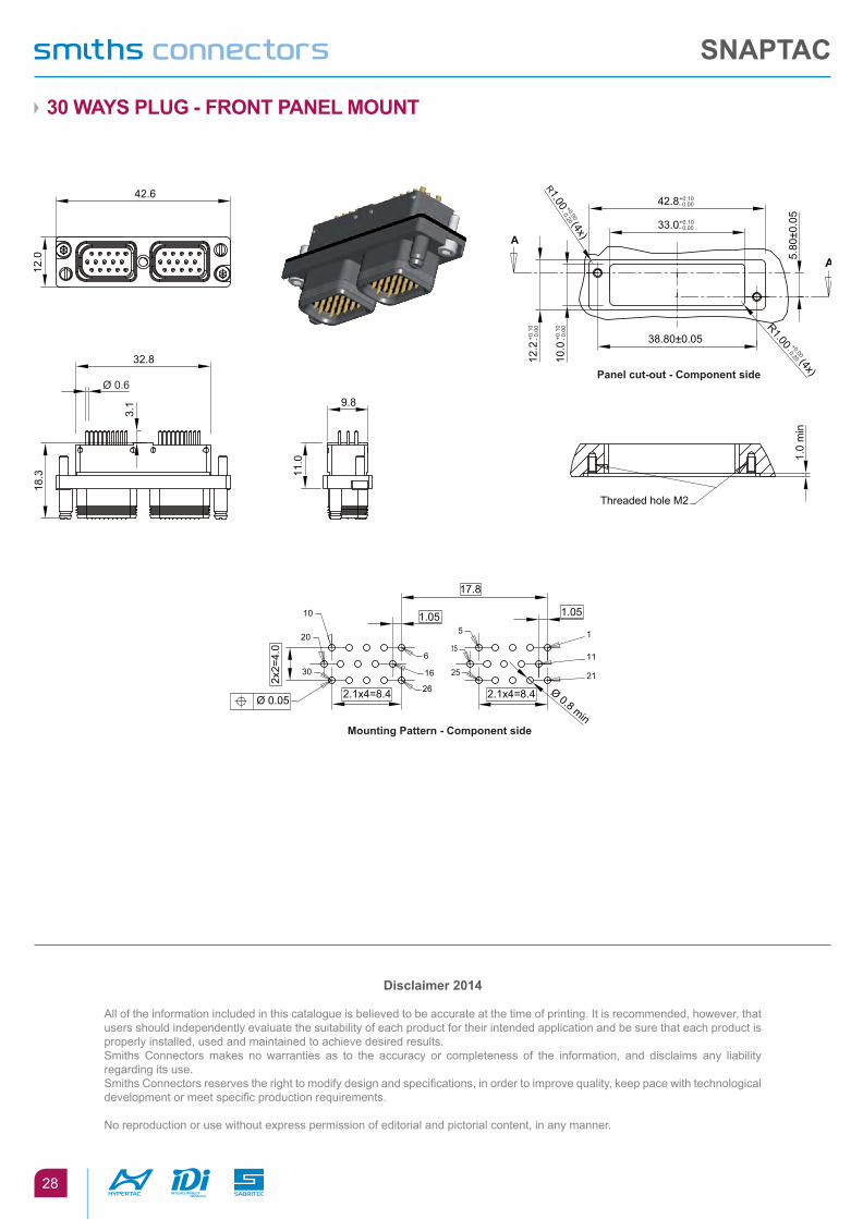
30 WaYS plug - fRONT paNEl MOuNT
A
Ø 0.8 min
17.8
1.05
2x2=
4.0
2.1x4=8.4
1.0
min
38.80±0.05
5.80
±0.0
5
Threaded hole M2
Ø 0.05
15
6
10
1115
16
20
2125
26
30
12.0
18.3
42.6
3.1
11.0
9.8
32.8
Ø 0.6Panel cut-out - Component side
12.2
+0.1
0- 0
.00
R1.00 +0.00
- 0.20 (4x)
R1.00 +0.00
- 0.20 (4x)
A
10.0
+0.1
0- 0
.00
42.8+0.10- 0.00
33.0+0.10- 0.00
Mounting Pattern - Component side
2.1x4=8.4
1.05
disclaimer 2014
All of the information included in this catalogue is believed to be accurate at the time of printing. It is recommended, however, that users should independently evaluate the suitability of each product for their intended application and be sure that each product is properly installed, used and maintained to achieve desired results.Smiths Connectors makes no warranties as to the accuracy or completeness of the information, and disclaims any liability regarding its use.Smiths Connectors reserves the right to modify design and specifications, in order to improve quality, keep pace with technological development or meet specific production requirements.
No reproduction or use without express permission of editorial and pictorial content, in any manner.
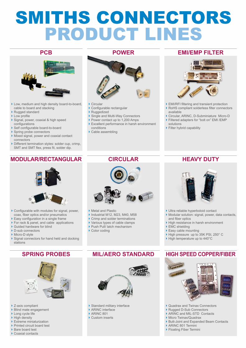
sMitHs connectors proDUct lines
pCb pOWER EMI/EMp fIlTER
Low, medium and high density board-to-board, cable to board and stacking
Rugged standard Low profile Signal, power, coaxial & high speed configurations
Self configurable board-to-board Spring probe connectors Mixed signal, power and coaxial contact connectors
Different termination styles: solder cup, crimp, SMT and SMT flex, press fit, solder dip.
Circular Configurable rectangular Ruggedized Single and Multi-Way Connectors Power contact up to 1,200 Amps Excellent performance in harsh environment conditions
Cable assembling
EMI/RFI filtering and transient protection RoHS compliant solderless filter connectors available
Circular, ARINC, D-Subminiature Micro-D Filtered adapters for “bolt on” EMI /EMP solutions
Filter hybrid capability
MOdulaR/RECTaNgulaR CIRCulaR hEaVY duTY
Configurable with modules for signal, power, coax, fiber optics and/or pneumatics
Easy configuration in a single frame For rack & panel, and cable applications Guided hardware for blind D-sub connectors Micro-D style Signal connectors for hand held and docking stations
Metal and Plastic Industrial M12, M23, M40, M58 Crimp and solder terminations Various types of cable clamps Push Pull/ latch mechanism Color coding
Ultra reliable hyperboloid contact Modular solution: signal, power, data contacts, and fiber optics
High resistance in harsh environment EMC shielding Easy cable mounting High pressure up to 35K PSI, 250° C High temperature up to 440°C
SpRINg pRObES MIl/aERO STaNdaRd hIgh SpEEd COppER/fIbER
Z-axis compliant Blind mate engagement Long cycle life High density Extreme miniaturization Printed circuit board test Bare board test Coaxial contacts
Standard military interface ARINC interface ARINC 801 Custom inserts
Quadrax and Twinax Connectors Rugged D-Sub Connectors ARINC and MIL-STD Contacts Micro Twinax/Quadrax Butt-Joint and Expanded Beam Contacts ARINC 801 Termini Floating Fiber Termini

SMITHS CONNECTORSGLOBAL SUPPORT
AMERICAS EUROPE [email protected]
Costa Mesa, CA 1.714.371.1100
Hudson, MA 1.978.568.0451
Kansas City, KS 1.913.342.5544
France [email protected]
Germany [email protected]
Italy [email protected]
United Kingdom [email protected]
Shanghai, China 86.21.3318.4650
Suzhou, China 86.512.6273.1188
Singapore 65.6846.1655
visit us at | smithsconnectors.com |
Copyright© 2016 Smiths Connectors | All rights reserved | Version 1.1