snb6500 eng - download.p4c.philips.com
TRANSCRIPT

SNB6500
User manual 3EN
☎ Helpline
België/Belgique/Belgien070 253 010 (. 0.17)
Luxemburg/Luxembourg26 84 30 00
Danmark 3525 8761
Deutschland 0180 5 007 532 (. 0.12)
España 902 888 785 (. 0.15)
France08 9165 0006 (. 0.23)
E���da 0 0800 3122 1223
Ireland01 601 1161
Italia 199 404 042 (. 0.25)
Cyprus 800 92256
Nederland 0900 0400 063 (. 0.20)
Norge 2270 8250
Österreich 01 546 575 603 (low rate)
Portugal2 1359 1440
Schweiz/Suisse/Svizzera02 2310 2116
Suomi 09 2290 1908
Sverige08 632 0016
Türkiye0800 2613302
UK (United Kingdom)0906 1010 017 (£ 0.15)
China 4008 800 008
European RegulationsThis product has been designed, tested and manufactured according to the European R&TTE Directive 1999/5/EC.
Following this Directive, this product can be brought into service in the following states:
B ✔ DK ✔ E ✔ GR ✔ F ✔
IRL ✔ I ✔ L ✔ NL ✔ A ✔
P ✔ SU ✔ S ✔ UK ✔ N ✔
D ✔ CH ✔
SNB6500/00/05
Contents....................................................................................3
Important safety information .................................................4Safety Precautions ...........................................................................................................................4Environmental information............................................................................................................4Disclaimer .........................................................................................................................................4
What’s in the box.....................................................................5
Introduction ..............................................................................6What are wireless network connections? ................................................................................6Factors determining your network range and network speed............................................6Securing your wireless network..................................................................................................6
Your Wireless Router..............................................................7
Install .........................................................................................8
Securing your Home Network .............................................13Firewall ............................................................................................................................................13Wireless encryption .....................................................................................................................14
Menu: Setup Wizard..............................................................22
Menu: Home Network Settings ...........................................23
Menu: Security Settings.........................................................25
Menu: Advanced Settings......................................................31
Configure Client PC...............................................................35
Finding the MAC address of a network card ......................41
How to set-up a computer network ....................................41
Troubleshooting .....................................................................47
Glossary of terms ...................................................................48
Technical Specifications ........................................................49
Contents EN
3
EN
4
• Please install and connect the product in the order as described in the ‘QuickStart Guide’ booklet only. This assures best installation results with the leasttechnical hassles.
• Please read this manual and the ‘Quick Start Guide’ booklet carefully before usingthe Wireless Router (SNB6500); and keep these documents for future reference.
• The most recent downloads and information on this product will be availablethrough our web site www.philips.com/support
• During set-up and installation, it may be helpful to have the instructions for yourPC and other network components at hand.
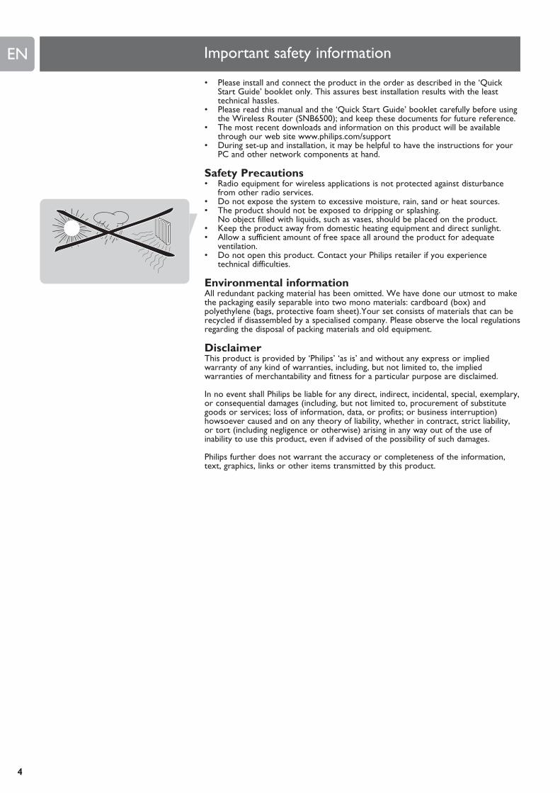
Safety Precautions• Radio equipment for wireless applications is not protected against disturbance
from other radio services.• Do not expose the system to excessive moisture, rain, sand or heat sources.• The product should not be exposed to dripping or splashing.
No object filled with liquids, such as vases, should be placed on the product.• Keep the product away from domestic heating equipment and direct sunlight.• Allow a sufficient amount of free space all around the product for adequate
ventilation.• Do not open this product. Contact your Philips retailer if you experience
technical difficulties.
Environmental informationAll redundant packing material has been omitted. We have done our utmost to makethe packaging easily separable into two mono materials: cardboard (box) andpolyethylene (bags, protective foam sheet).Your set consists of materials that can berecycled if disassembled by a specialised company. Please observe the local regulationsregarding the disposal of packing materials and old equipment.
DisclaimerThis product is provided by ‘Philips’ ‘as is’ and without any express or impliedwarranty of any kind of warranties, including, but not limited to, the impliedwarranties of merchantability and fitness for a particular purpose are disclaimed.
In no event shall Philips be liable for any direct, indirect, incidental, special, exemplary,or consequential damages (including, but not limited to, procurement of substitutegoods or services; loss of information, data, or profits; or business interruption)howsoever caused and on any theory of liability, whether in contract, strict liability,or tort (including negligence or otherwise) arising in any way out of the use ofinability to use this product, even if advised of the possibility of such damages.
Philips further does not warrant the accuracy or completeness of the information,text, graphics, links or other items transmitted by this product.
Important safety information

EN
5
What’s in the box
SNB6500
Ethernet Cable
Quick Start Guide
Power Supply
Antenna
Installation CD
WelcomeQuick Start Guide
1
2
3
Connect
Install
Enjoy
ADSL Wireless Base Station
SNB6500
English
Wireless Base Station 11g True Turbo
1 2 3 4 Wireless Internet Modem Power
What else you will need
Computer Broadband modem Ethernet Network Card(cable modem or or Wi-Fi adapter
ADSL modem) with Ethernet port
(Broadband modems with a USB connector
are not supported)
SNB6500Thank you for purchasing the Philips Wireless Router. This Philips Wireless Router isa WiFi (IEEE 802.11b/g) compatible device. It fully supports high data rates up to 108Mbps with automatic fallback to lower speeds for secure operation at lower datarates in even the most difficult of wireless environments.
In this manual we will expand on how to install, configure, and use your PhilipsWireless Router.
This chapter will give you background information on wireless networks and theirsecurity in general.
What are wireless network connections?Your Wireless Router uses a wireless protocol (called IEEE 802.11b/g or WiFi) tocommunicate with other network computers by means of radio transmissions. WiFiradio waves travel outwards from the antenna in all directions, and can transmitthrough walls and floors. Wireless transmissions can theoretically reach up to 450 meters in an open environment and reach speeds of up to 108 Megabits persecond (Mbps) at close range. However, the actual network range and datathroughput rate will be less, depending on the wireless link quality.
Factors determining your network range and networkspeed• The environment: Radio signals can travel further outside of buildings, and if the
wireless components are in direct line of sight to one another. Putting wirelesscomponents in high places helps avoid physical obstacles and provides bettercoverage.
• Building construction such as metal framing and concrete or masonry walls andfloors will reduce radio signal strength. Avoid putting wireless components nextto walls and other large, solid objects; or next to large metal objects such ascomputers, monitors, and appliances.
• Wireless signal range, speed, and strength can be affected by interference fromneighbouring wireless networks and devices. Electro-magnetic devices such astelevisions, radios, microwave ovens, and cordless phones, especially those withfrequencies in the 2.4 GHz range, may also interfere with wireless transmission.
• Standing or sitting too close to wireless equipment can also affect radio signalquality.
• Adjusting the antenna: Do not place antennas next to large pieces of metal,because this might cause interference.
Securing your wireless networkAs wireless computer networks use radio signals, it is possible for other wirelessnetwork devices outside your immediate area to pick up the wireless signals andeither connect to your network or to capture the network traffic.Therefore, youshould always enable the Wired Equivalent Privacy (WEP) or WiFi Protected Access(WPA/WPA2) network encryption key to help prevent unauthorised connectionsor the possibility of eavesdroppers listening in on your network traffic.
For an example of how to secure your network, please see the chapter on Securingyour wireless network.
EN
6
Introduction
Your Wireless Router EN
7
Wireless Base Station 11g True Turbo
1 2 3 4 Wireless Internet Modem Power
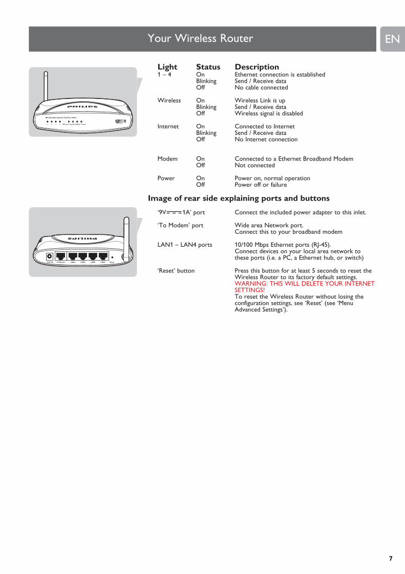
Light Status Description1 – 4 On Ethernet connection is established
Blinking Send / Receive dataOff No cable connected
Wireless On Wireless Link is upBlinking Send / Receive dataOff Wireless signal is disabled
Internet On Connected to InternetBlinking Send / Receive dataOff No Internet connection
Modem On Connected to a Ethernet Broadband ModemOff Not connected
Power On Power on, normal operationOff Power off or failure
Image of rear side explaining ports and buttons
‘9V 1A’ port Connect the included power adapter to this inlet.
‘To Modem’ port Wide area Network port. Connect this to your broadband modem
LAN1 – LAN4 ports 10/100 Mbps Ethernet ports (RJ-45). Connect devices on your local area network tothese ports (i.e. a PC, a Ethernet hub, or switch)
‘Reset’ button Press this button for at least 5 seconds to reset theWireless Router to its factory default settings.WARNING: THIS WILL DELETE YOUR INTERNETSETTINGS!To reset the Wireless Router without losing theconfiguration settings, see ‘Reset’ (see ‘MenuAdvanced Settings’).
LAN4To Modem12V=1A ResetLAN3 LAN2 LAN1
Wireless Base Station 11g True Turbo
1 2 3 4 Wireless Internet Modem Power
LAN4To Modem12V=1A ResetLAN3 LAN2 LAN1
EN
8
Install
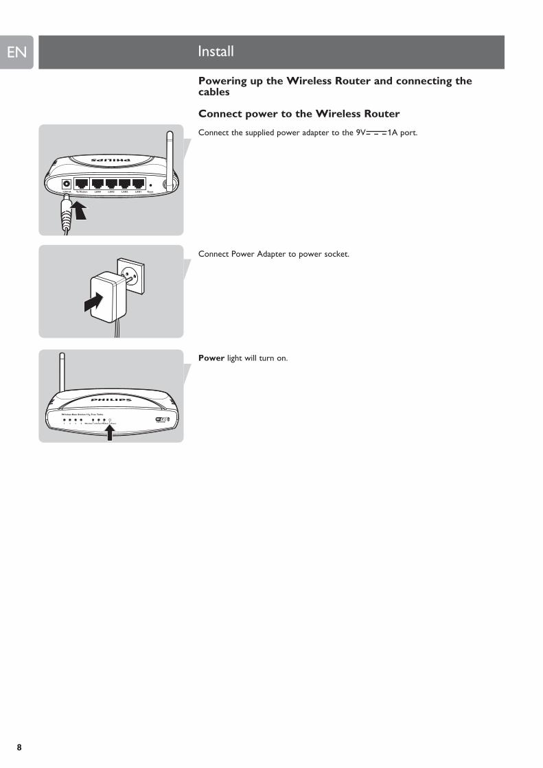
Powering up the Wireless Router and connecting thecables
Connect power to the Wireless Router
Connect the supplied power adapter to the 9V 1A port.
Connect Power Adapter to power socket.
Power light will turn on.
EN
9
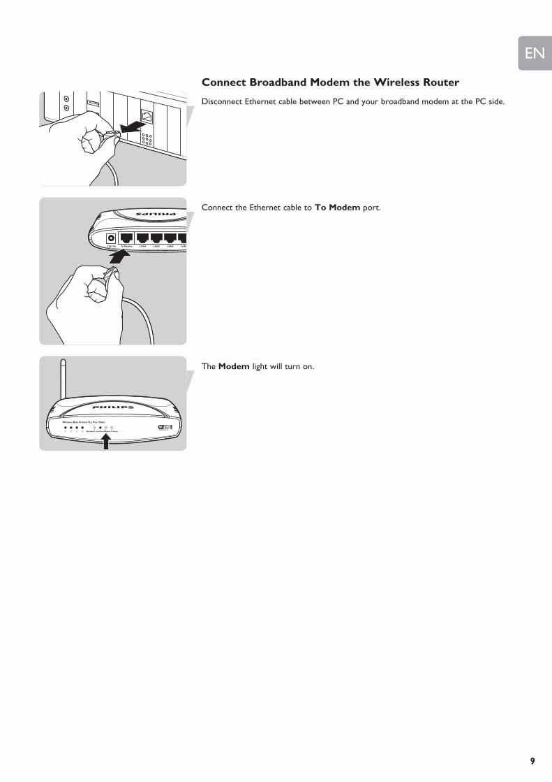
Connect Broadband Modem the Wireless Router
Disconnect Ethernet cable between PC and your broadband modem at the PC side.
Connect the Ethernet cable to To Modem port.
The Modem light will turn on.
LAN4To Modem12V=1A LAN3 LAN2 LAN1
Wireless Base Station 11g True Turbo
1 2 3 4 Wireless Internet Modem Power

EN
10
Connect PC to Wireless Router: Wired
Take the supplied Ethernet cable.
Connect one end of the Ethernet cable to LAN1 port on SNB6500.
Connect other end of Ethernet cable to your PC network card.
Network card must be configured to obtain an ip address automatically(see chapter “Configuring Client PC”)
Light 1 on the front will turn on.
LAN4To Modem12V=1A ResetLAN3 LAN2 LAN1
Wireless Base Station 11g True Turbo
1 2 3 4 Wireless Internet Modem Power
EN
11
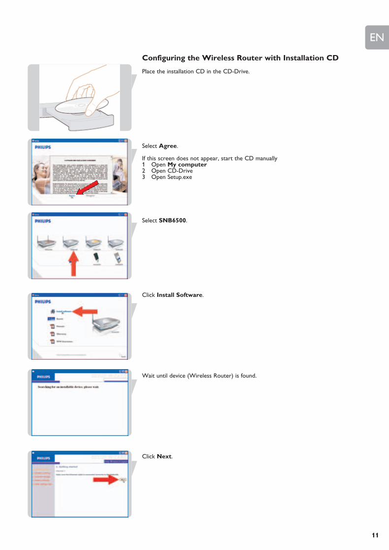
Configuring the Wireless Router with Installation CD
Place the installation CD in the CD-Drive.
Select Agree.
If this screen does not appear, start the CD manually1 Open My computer2 Open CD-Drive3 Open Setup.exe
Select SNB6500.
Click Install Software.
Wait until device (Wireless Router) is found.
Click Next.

EN
12
Click Next.
Select your Broadband modem type (DHCP).
Enter your Broadband Settings.These settings should be provided to you by your ISP.
(this example shows the cable modem configuration)
Wait until your settings have been saved.
Click LOGIN (Enter password if set).
The status window will show you are connected to the Internet.
EN
13
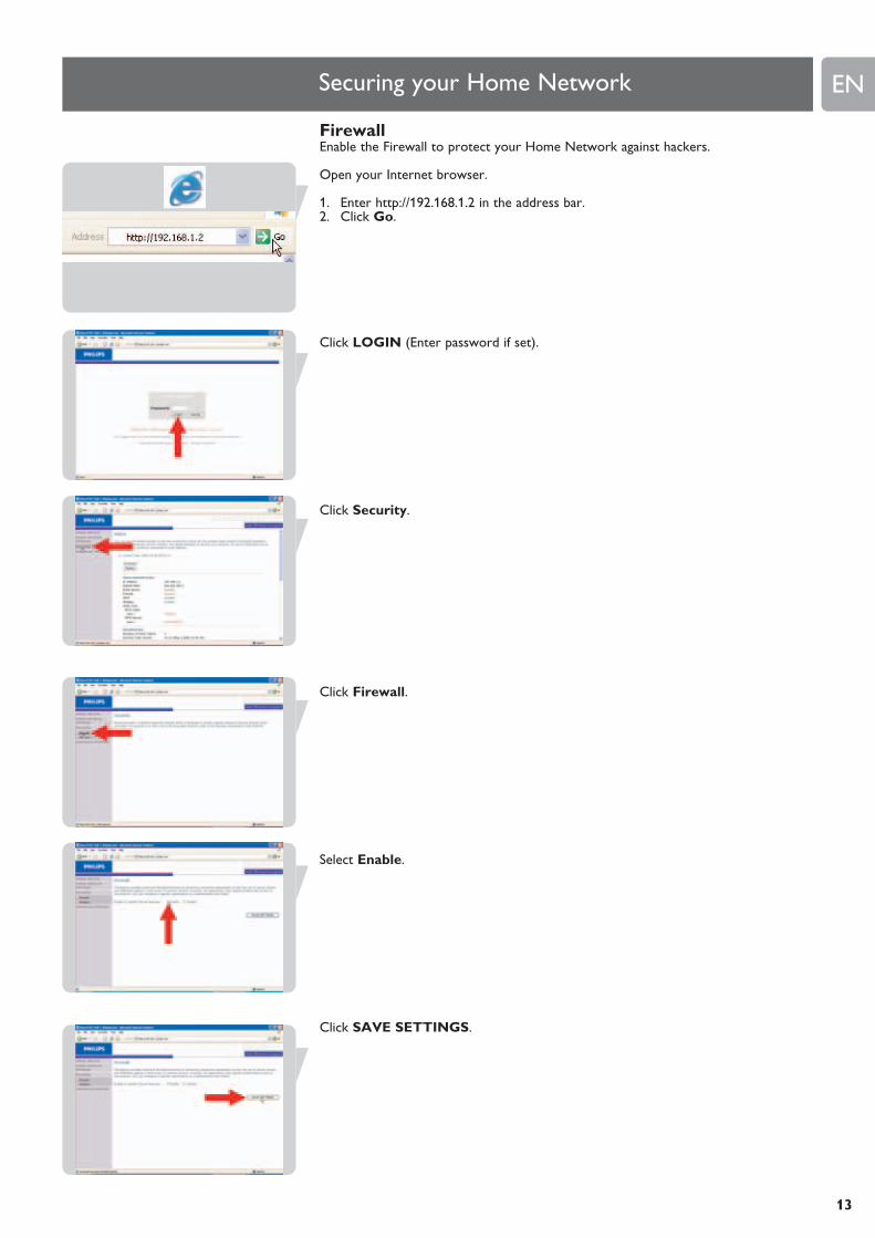
FirewallEnable the Firewall to protect your Home Network against hackers.
Open your Internet browser.
1. Enter http://192.168.1.2 in the address bar.2. Click Go.
Click LOGIN (Enter password if set).
Click Security.
Click Firewall.
Select Enable.
Click SAVE SETTINGS.
Securing your Home Network

EN
14
Wireless encryptionEnable Wireless Encryption to prevent others from eavesdropping your wirelessconnection.
Wi-Fi Protected Access (WPA/WPA2)Step 1: Setup the WPA/WPA2 encryption
Open your Internet browser
1. Enter http://192.168.1.2 in the address bar.2. Click Go.
Click LOGIN (Enter password if set).
Click Security.
Click Wireless.
Select WPA&WPA2.
2
1
Step 1

EN
15
1 Enter your Pre-shared Key (= password or passphrase)2 Click SAVE SETTINGS.
WARNING: WPA/WPA2 encryption is still not active atthis point
Step 2: Enable WPA/WPA2 Encryption.
Click Wireless Encryption.
1. Select WPA/WPA2 Only2 Click SAVE SETTINGS.
WPA/WPA2 encryption is now active.
21
2
1
Step 2
EN
16
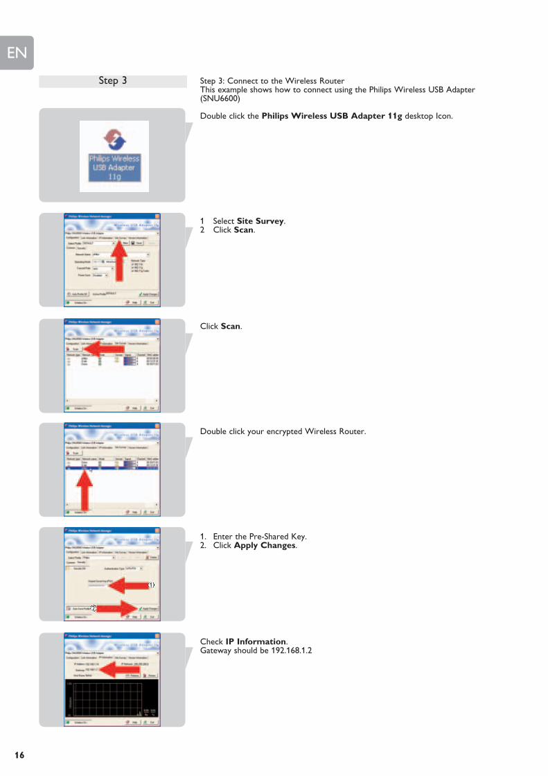
Step 3: Connect to the Wireless RouterThis example shows how to connect using the Philips Wireless USB Adapter(SNU6600)
Double click the Philips Wireless USB Adapter 11g desktop Icon.
1 Select Site Survey.2 Click Scan.
Click Scan.
Double click your encrypted Wireless Router.
1. Enter the Pre-Shared Key.2. Click Apply Changes.
Check IP Information.Gateway should be 192.168.1.2
2
1
Step 3
EN
17
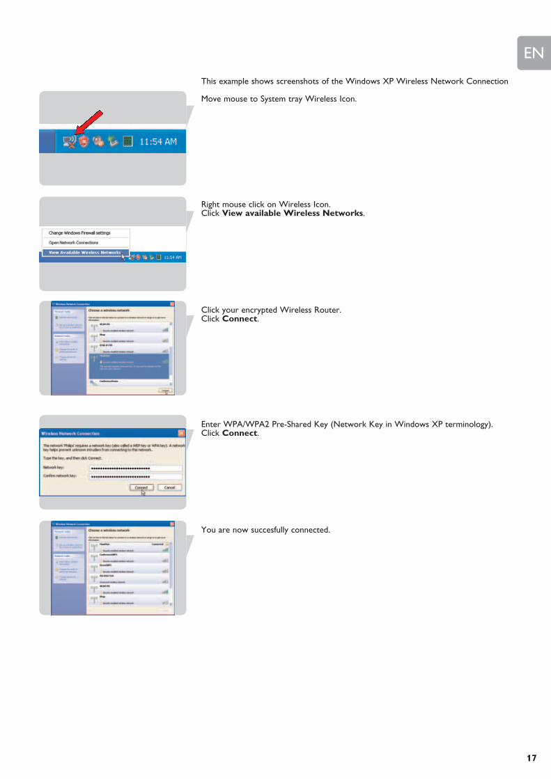
This example shows screenshots of the Windows XP Wireless Network Connection
Move mouse to System tray Wireless Icon.
Right mouse click on Wireless Icon.Click View available Wireless Networks.
Click your encrypted Wireless Router.Click Connect.
Enter WPA/WPA2 Pre-Shared Key (Network Key in Windows XP terminology).Click Connect.
You are now succesfully connected.
EN
18
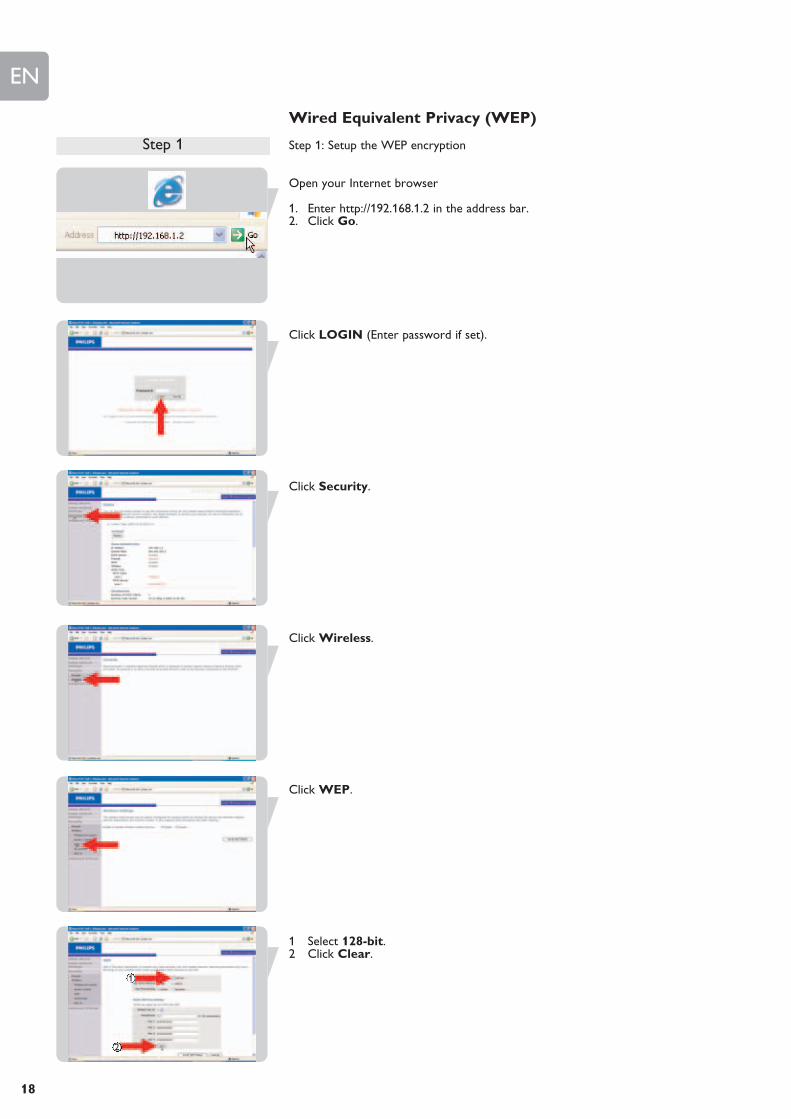
Wired Equivalent Privacy (WEP)
Step 1: Setup the WEP encryption
Open your Internet browser
1. Enter http://192.168.1.2 in the address bar.2. Click Go.
Click LOGIN (Enter password if set).
Click Security.
Click Wireless.
Click WEP.
1 Select 128-bit.2 Click Clear.
2
1
Step 1
EN
19
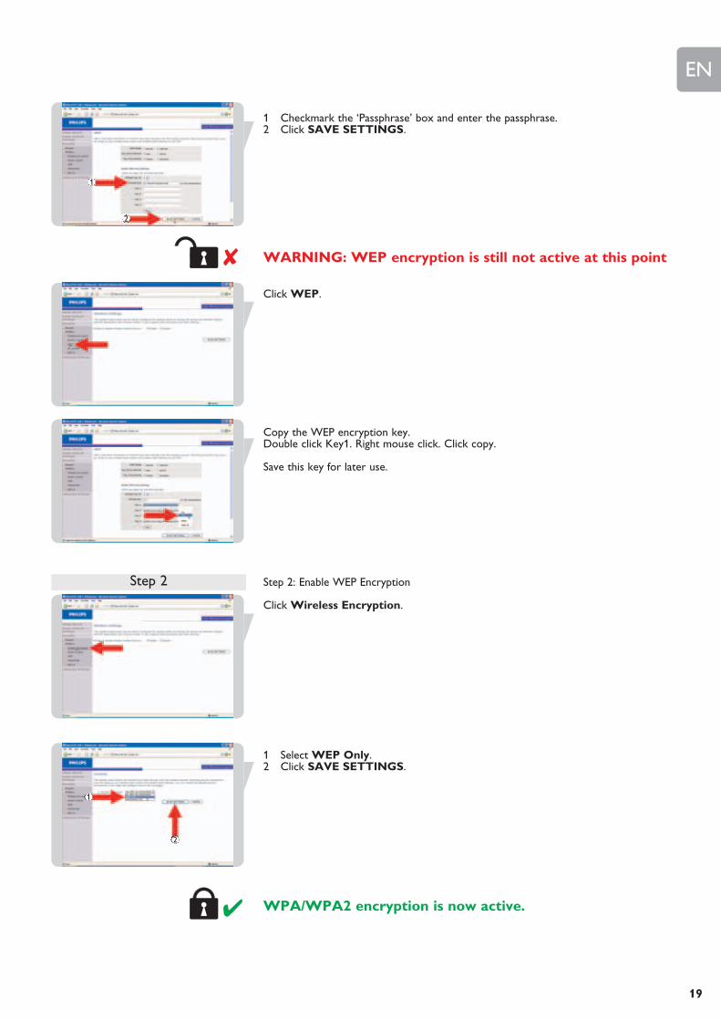
1 Checkmark the ‘Passphrase’ box and enter the passphrase.2 Click SAVE SETTINGS.
WARNING: WEP encryption is still not active at this point
Click WEP.
Copy the WEP encryption key.Double click Key1. Right mouse click. Click copy.
Save this key for later use.
Step 2: Enable WEP Encryption
Click Wireless Encryption.
1 Select WEP Only.2 Click SAVE SETTINGS.
WPA/WPA2 encryption is now active.
2
1
Step 2
2
1
EN
20
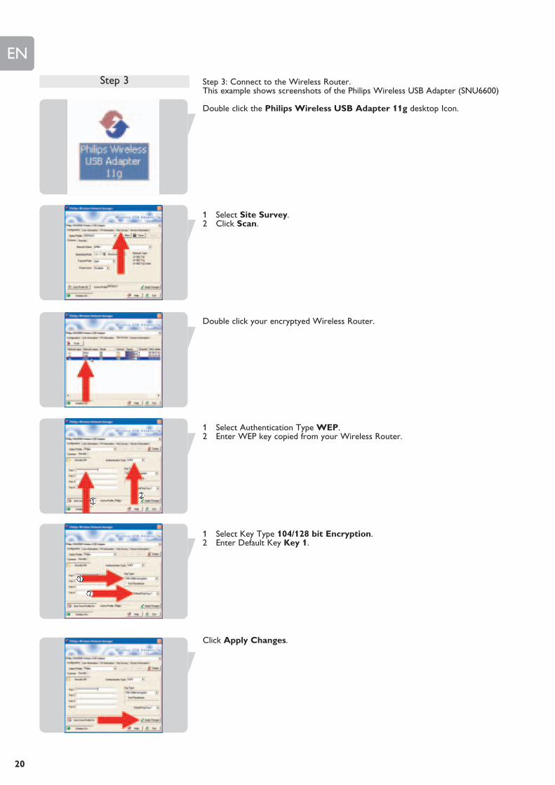
Step 3: Connect to the Wireless Router.This example shows screenshots of the Philips Wireless USB Adapter (SNU6600)
Double click the Philips Wireless USB Adapter 11g desktop Icon.
1 Select Site Survey.2 Click Scan.
Double click your encryptyed Wireless Router.
1 Select Authentication Type WEP.2 Enter WEP key copied from your Wireless Router.
1 Select Key Type 104/128 bit Encryption.2 Enter Default Key Key 1.
Click Apply Changes.
Step 3
2
1
21

EN
21
Check Gateway IP status
Gateway should be 192.168.1.2
Step3: Connect to the Wireless RouterThis example shows how to connect to the Wireless Router using Windows XP.
Move mouse to System tray Wireless Icon
Right mouse click on Wireless Icon.Click View available Wireless Networks.
Click your encrypted Wireless Router.Click Connect.
Enter WEP (Network Key in Windows XP terminology)Click Connect.
You are now successfully connected
Step 3
EN
22
Menu: Setup Wizard
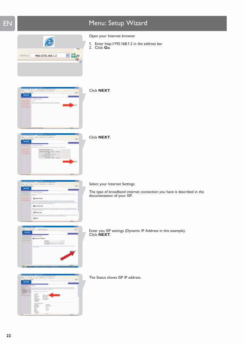
Open your Internet browser
1. Enter http://192.168.1.2 in the address bar2. Click Go.
Click NEXT.
Click NEXT.
Select your Internet Settings.
The type of broadband internet connection you have is described in thedocumentation of your ISP.
Enter you ISP settings (Dynamic IP Address in this example).Click NEXT.
The Status shows ISP IP address.
EN
23
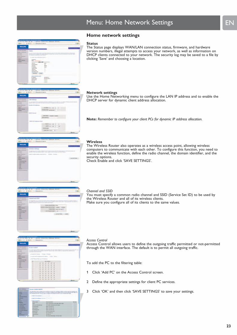
Home network settings
StatusThe Status page displays WAN/LAN connection status, firmware, and hardwareversion numbers, illegal attempts to access your network, as well as information onDHCP clients connected to your network. The security log may be saved to a file byclicking ‘Save’ and choosing a location.
Network settingsUse the Home Networking menu to configure the LAN IP address and to enable theDHCP server for dynamic client address allocation.
Note: Remember to configure your client PCs for dynamic IP address allocation.
WirelessThe Wireless Router also operates as a wireless access point, allowing wirelesscomputers to communicate with each other. To configure this function, you need toenable the wireless function, define the radio channel, the domain identifier, and thesecurity options. Check Enable and click ‘SAVE SETTINGS’.
Channel and SSIDYou must specify a common radio channel and SSID (Service Set ID) to be used bythe Wireless Router and all of its wireless clients. Make sure you configure all of its clients to the same values.
Access ControlAccess Control allows users to define the outgoing traffic permitted or not-permittedthrough the WAN interface. The default is to permit all outgoing traffic.
To add the PC to the filtering table:
1 Click ‘Add PC’ on the Access Control screen.
2 Define the appropriate settings for client PC services.
3 Click ‘OK’ and then click ‘SAVE SETTINGS’ to save your settings.
Menu: Home Network Settings

EN
24
WDSIf the signal strength of a single Wireless Router is not sufficient due to a largecoverage area or attenuation due to walls, with WDS the range of a Wireless Routercan be extended.
All Routers in a Wireless Distribution System must be configured with the sameradio channel, and encryption type (WEP / WPA/WPA2) if that is used.
Note: The WDS feature is not completely specified in IEEE or Wifi standards. Therefore itcannot be guaranteed that WDS will work with products of different vendors.
WEPIf you use WEP to protect your wireless network, you need to set the sameparameters for the Wireless Router and all your wireless clients.
You may automatically generate encryption keys or manually enter the keys. Togenerate the key automatically with passphrase, check the Passphrase box, enter astring of characters. Select the default key from the drop down menu. Click ‘SAVESETTINGS’.
Note: The passphrase can consist of up to 32 alphanumeric characters.
To manually configure the encryption key, enter five hexadecimal pairs of digits foreach 64-bit key, or enter 13 pairs for the single 128-bit key. (A hexadecimal digit is a number or letter in the range 0-9 or A-F.) Note that WEP protects data transmitted between wireless nodes, but does notprotect any transmissions over your wired network or over the Internet.
WPA/WPA2Wi-Fi Protected Access (WPA/WPA2) combines temporal key integrity protocol(TKIP) and 802.1x mechanisms. It provides dynamic key encryption and 802.1xauthentication service.
802.1XIf 802.1x is used in your network, then you should enable this function for theWireless Router. These parameters are used for the Wireless Router to connect tothe authentication server.
EN
25
Security
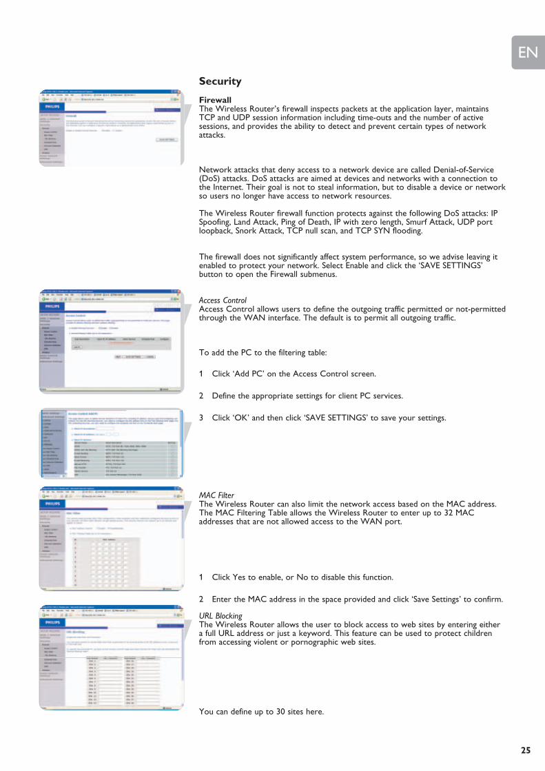
FirewallThe Wireless Router’s firewall inspects packets at the application layer, maintainsTCP and UDP session information including time-outs and the number of activesessions, and provides the ability to detect and prevent certain types of networkattacks.
Network attacks that deny access to a network device are called Denial-of-Service(DoS) attacks. DoS attacks are aimed at devices and networks with a connection tothe Internet. Their goal is not to steal information, but to disable a device or networkso users no longer have access to network resources.
The Wireless Router firewall function protects against the following DoS attacks: IPSpoofing, Land Attack, Ping of Death, IP with zero length, Smurf Attack, UDP portloopback, Snork Attack, TCP null scan, and TCP SYN flooding.
The firewall does not significantly affect system performance, so we advise leaving itenabled to protect your network. Select Enable and click the ‘SAVE SETTINGS’button to open the Firewall submenus.
Access ControlAccess Control allows users to define the outgoing traffic permitted or not-permittedthrough the WAN interface. The default is to permit all outgoing traffic.
To add the PC to the filtering table:
1 Click ‘Add PC’ on the Access Control screen.
2 Define the appropriate settings for client PC services.
3 Click ‘OK’ and then click ‘SAVE SETTINGS’ to save your settings.
MAC FilterThe Wireless Router can also limit the network access based on the MAC address.The MAC Filtering Table allows the Wireless Router to enter up to 32 MACaddresses that are not allowed access to the WAN port.
1 Click Yes to enable, or No to disable this function.
2 Enter the MAC address in the space provided and click ‘Save Settings’ to confirm.
URL BlockingThe Wireless Router allows the user to block access to web sites by entering eithera full URL address or just a keyword. This feature can be used to protect childrenfrom accessing violent or pornographic web sites.
You can define up to 30 sites here.

EN
26
Schedule RuleYou may filter Internet access for local clients based on rules. Each access controlrule may be activated at a scheduled time. Define the time schedule on this page, andapply the rule on the Access Control page.
Intrusion Detection
Intrusion Detection FeatureStateful Packet Inspection (SPI) and Anti-DoS firewall protection (Default: Enabled) - The Intrusion Detection Feature of the Wireless Router limitsaccess for incoming traffic at the WAN port. When the SPI feature is turned on, allincoming packets will be blocked except for those types marked in the Stateful PacketInspection section.
RIP Defect (Default: Disabled) - If an RIP request packet is not acknowledged to bythe router, it will stay in the input queue and not be released. Accumulated packetscould cause the input queue to fill, causing severe problems for all protocols. Enablingthis feature prevents the packets from accumulating.
Discard Ping to WAN (Default: Disabled) - Prevent a ping on the Wireless Router’sWAN port from being routed to the network.
Scroll down to view more information.
Stateful Packet InspectionThis is called a ‘stateful’ packet inspection because it examines the contents of thepacket to determine the state of the communications; i.e., it ensures that the stateddestination computer has previously requested the current communication. This is away of ensuring that all communications are initiated by the recipient computer andare taking place only with sources that are known and trusted from previousinteractions. In addition to being more rigorous in their inspection of packets, statefulinspection firewalls also close off ports until connection to the specific port isrequested.
When particular types of traffic are checked, only the particular type of trafficinitiated from the internal LAN will be allowed. For example, if the user only checks‘FTP Service’ in the Stateful Packet Inspection section, all incoming traffic will beblocked except for FTP connections initiated from the local LAN.
Stateful Packet Inspection allows you to select different application types that areusing dynamic port numbers. If you wish to use the Stateful Packet Inspection (SPI) toblock packets, click on the Yes radio button in the ‘Enable SPI and Anti-DoS firewallprotection’ field and then check the inspection type that you need, such as Packet Fragmentation, TCP Connection, UDP Session, FTP Service, H.323 Service, or TFTP Service.
When hackers attempt to enter your network, the SNB6500 can alert youby e-mail
If the mail server needs to authenticate your identification before sending out any e-mail, please fill related information in POP3 server, username and password fields.Otherwise leave the three fields blank.
Connection PolicyEnter the appropriate values for TCP/UDP sessions as described in the followingtable.
Note: The firewall does not significantly affect system performance, so we advise enablingthe prevention features to protect your network.
DMZIf you have a client PC that cannot run an Internet application properly from behindthe firewall, you can open the client up to unrestricted two-way Internet access.Enter the IP address of a DMZ (Demilitarized Zone) host on this screen. Adding aclient to the DMZ may expose your local network to a variety of security risks, soonly use this option as a last resort.

EN
27
Wireless security
Wireless EncryptionTo make your wireless network safe, you should turn on the security function. The Wireless Router supports WEP (Wired Equivalent Privacy), WPA/WPA2 (Wi-Fi Protected Access), and 802.1x security mechanisms.
Access ControlAccess Control allows users to define the outgoing traffic permitted or not-permittedthrough the WAN interface. The default is to permit all outgoing traffic.
To add the PC to the filtering table:
1 Click ‘Add PC’ on the Access Control screen.
2 Define the appropriate settings for client PC services.
3 Click ‘OK’ and then click ‘SAVE SETTINGS’ to save your settings.
MAC FilterThe Wireless Router can also limit the network access based on the MAC address.The MAC Filtering Table allows the Wireless Router to enter up to 32 MACaddresses that are not allowed access to the WAN port.
1 Click Yes to enable, or No to disable this function.
2 Enter the MAC address in the space provided and click ‘Save Settings’ to confirm.
Note: Also see ‘Finding the MAC address of a network card’.
WEPIf you use WEP to protect your wireless network, you need to set the sameparameters for the Wireless Router and all your wireless clients.
You may automatically generate encryption keys or manually enter the keys. To generate the key automatically with passphrase, check the Passphrase box, enter astring of characters. Select the default key from the drop down menu. Click ‘SAVE SETTINGS’.
Note: The passphrase can consist of up to 32 alphanumeric characters.
To manually configure the encryption key, enter five hexadecimal pairs of digits foreach 64-bit key, or enter 13 pairs for the single 128-bit key. (A hexadecimal digit is a number or letter in the range 0-9 or A-F.) Note that WEP protects data transmitted between wireless nodes, but does notprotect any transmissions over your wired network or over the Internet.
EN
28
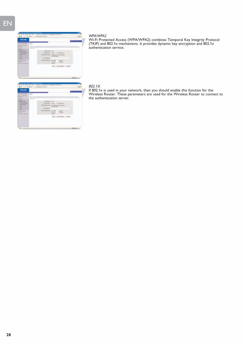
WPA/WPA2Wi-Fi Protected Access (WPA/WPA2) combines Temporal Key Integrity Protocol(TKIP) and 802.1x mechanisms. It provides dynamic key encryption and 802.1xauthentication service.
802.1XIf 802.1x is used in your network, then you should enable this function for theWireless Router. These parameters are used for the Wireless Router to connect tothe authentication server.

EN
29
Home network settings
StatusThe Status page displays WAN/LAN connection status, firmware, and hardwareversion numbers, illegal attempts to access your network, as well as information onDHCP clients connected to your network. The security log may be saved to a file byclicking ‘Save’ and choosing a location.
Network settingsUse the Home Networking menu to configure the LAN IP address and to enable theDHCP server for dynamic client address allocation.
Note: Remember to configure your client PCs for dynamic IP address allocation.
WirelessThe Wireless Router also operates as a wireless access point, allowing wirelesscomputers to communicate with each other. To configure this function, you need toenable the wireless function, define the radio channel, the domain identifier, and thesecurity options. Check Enable and click ‘SAVE SETTINGS’.
Channel and SSIDYou must specify a common radio channel and SSID (Service Set ID) to be used bythe Wireless Router and all of its wireless clients. Make sure you configure all of its clients to the same values.
Access ControlAccess Control allows users to define the outgoing traffic permitted or not-permittedthrough the WAN interface. The default is to permit all outgoing traffic.
To add the PC to the filtering table:
1 Click ‘Add PC’ on the Access Control screen.
2 Define the appropriate settings for client PC services.
3 Click ‘OK’ and then click ‘SAVE SETTINGS’ to save your settings.

EN
30
WDSIf the signal strength of a single Wireless Router is not sufficient due to a largecoverage area or attenuation due to walls, with WDS the range of a Wireless Routercan be extended.
All Routers and wireless range extenders (i.e. SNR 6500) in a Wireless DistributionSystem must be configured with the same radio channel, and encryption type (WEP /WPA/WPA2) if that is used.
Note: The WDS feature is not completely specified in IEEE or Wifi standards. Therefore itcannot be guaranteed that WDS will work with products of different vendors.
WEPIf you use WEP to protect your wireless network, you need to set the sameparameters for the Wireless Router and all your wireless clients.
You may automatically generate encryption keys or manually enter the keys. To generate the key automatically with passphrase, check the Passphrase box, enter astring of characters. Select the default key from the drop down menu. Click ‘SAVESETTINGS’.
Note: The passphrase can consist of up to 32 alphanumeric characters.
To manually configure the encryption key, enter five hexadecimal pairs of digits foreach 64-bit key, or enter 13 pairs for the single 128-bit key. (A hexadecimal digit is a number or letter in the range 0-9 or A-F.) Note that WEP protects data transmitted between wireless nodes, but does notprotect any transmissions over your wired network or over the Internet.
WPA/WPA2Wi-Fi Protected Access (WPA/WPA2) combines Temporal Key Integrity Protocol(TKIP) and 802.1x mechanisms. It provides dynamic key encryption and 802.1x authentication service.
802.1XIf 802.1x is used in your network, then you should enable this function for theWireless Router. These parameters are used for the Wireless Router to connect tothe authentication server.
EN
31
Advanced settings
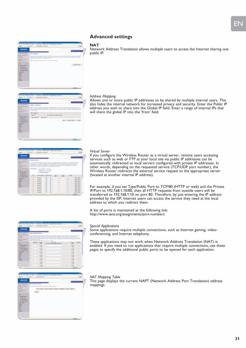
NATNetwork Address Translation allows multiple users to access the Internet sharing onepublic IP.
Address MappingAllows one or more public IP addresses to be shared by multiple internal users. Thisalso hides the internal network for increased privacy and security. Enter the Public IPaddress you wish to share into the Global IP field. Enter a range of internal IPs thatwill share the global IP into the ‘from’ field.
Virtual ServerIf you configure the Wireless Router as a virtual server, remote users accessingservices such as web or FTP at your local site via public IP addresses can beautomatically redirected to local servers configured with private IP addresses. Inother words, depending on the requested service (TCP/UDP port number), theWireless Router redirects the external service request to the appropriate server(located at another internal IP address).
For example, if you set Type/Public Port to TCP/80 (HTTP or web) and the PrivateIP/Port to 192.168.1.10/80, then all HTTP requests from outside users will betransferred to 192.168.1.10 on port 80. Therefore, by just entering the IP addressprovided by the ISP, Internet users can access the service they need at the localaddress to which you redirect them.
A list of ports is maintained at the following link:http://www.iana.org/assignments/port-numbers.
Special ApplicationsSome applications require multiple connections, such as Internet gaming, video-conferencing, and Internet telephony.
These applications may not work when Network Address Translation (NAT) isenabled. If you need to run applications that require multiple connections, use thesepages to specify the additional public ports to be opened for each application.
NAT Mapping TableThis page displays the current NAPT (Network Address Port Translation) addressmappings.
EN
32
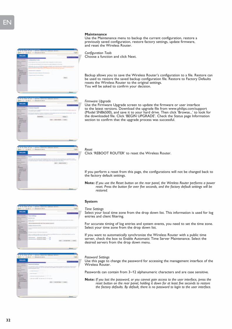
MaintenanceUse the Maintenance menu to backup the current configuration, restore apreviously saved configuration, restore factory settings, update firmware,and reset the Wireless Router.
Configuration ToolsChoose a function and click Next.
Backup allows you to save the Wireless Router’s configuration to a file. Restore canbe used to restore the saved backup configuration file. Restore to Factory Defaultsresets the Wireless Router to the original settings. You will be asked to confirm your decision.
Firmware UpgradeUse the Firmware Upgrade screen to update the firmware or user interfaceto the latest versions. Download the upgrade file from www.philips.com/support(Model SNB6500), and save it to your hard drive. Then click ‘Browse...’ to look forthe downloaded file. Click ‘BEGIN UPGRADE’. Check the Status page Informationsection to confirm that the upgrade process was successful.
ResetClick ‘REBOOT ROUTER’ to reset the Wireless Router.
If you perform a reset from this page, the configurations will not be changed back tothe factory default settings.
Note: If you use the Reset button on the rear panel, the Wireless Router performs a powerreset. Press the button for over five seconds, and the factory default settings will berestored.
System
Time SettingsSelect your local time zone from the drop down list. This information is used for logentries and client filtering.
For accurate timing of log entries and system events, you need to set the time zone.Select your time zone from the drop down list.
If you want to automatically synchronize the Wireless Router with a public timeserver, check the box to Enable Automatic Time Server Maintenance. Select thedesired servers from the drop down menu.
Password SettingsUse this page to change the password for accessing the management interface of theWireless Router.
Passwords can contain from 3~12 alphanumeric characters and are case sensitive.
Note: If you lost the password, or you cannot gain access to the user interface, press thereset button on the rear panel, holding it down for at least five seconds to restorethe factory defaults. By default, there is no password to login to the user interface.
EN
33
WARNING! When you reset the Wireless Router using the blue reset button all configuration settings willbe lost, also your ISP settings.
Enter a maximum Idle Time Out (in minutes) to define a maximum period of time forwhich the login session is maintained during inactivity. If the connection is inactive for longer than the maximum idle time, it will perform system logout, and you have to log in again to access the managementinterface. (Default: 10 minutes)
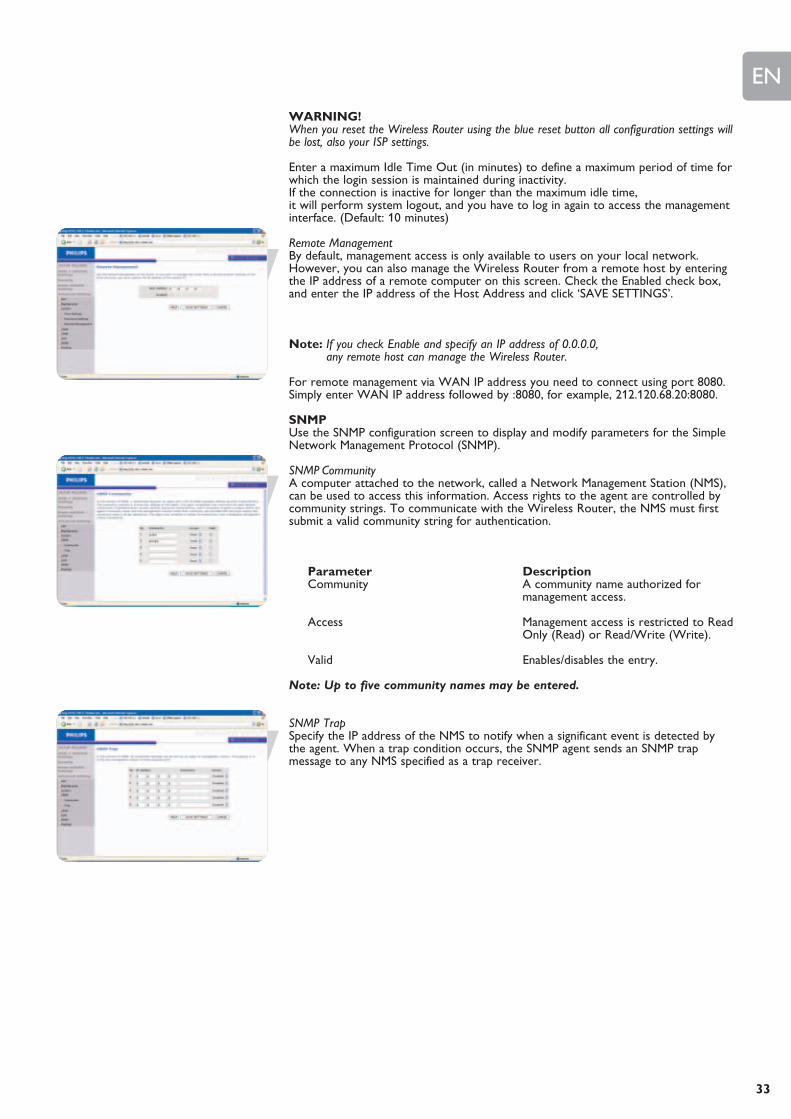
Remote ManagementBy default, management access is only available to users on your local network.However, you can also manage the Wireless Router from a remote host by enteringthe IP address of a remote computer on this screen. Check the Enabled check box,and enter the IP address of the Host Address and click ‘SAVE SETTINGS’.
Note: If you check Enable and specify an IP address of 0.0.0.0, any remote host can manage the Wireless Router.
For remote management via WAN IP address you need to connect using port 8080.Simply enter WAN IP address followed by :8080, for example, 212.120.68.20:8080.
SNMPUse the SNMP configuration screen to display and modify parameters for the SimpleNetwork Management Protocol (SNMP).
SNMP CommunityA computer attached to the network, called a Network Management Station (NMS),can be used to access this information. Access rights to the agent are controlled bycommunity strings. To communicate with the Wireless Router, the NMS must firstsubmit a valid community string for authentication.
Parameter DescriptionCommunity A community name authorized for
management access.
Access Management access is restricted to ReadOnly (Read) or Read/Write (Write).
Valid Enables/disables the entry.
Note: Up to five community names may be entered.
SNMP TrapSpecify the IP address of the NMS to notify when a significant event is detected bythe agent. When a trap condition occurs, the SNMP agent sends an SNMP trapmessage to any NMS specified as a trap receiver.

EN
34
UPNP (Universal Plug and Play) settingsWith Universal Plug and Play, a device can automatically dynamically join a network,obtain an IP address, communicate its capabilities, and learn about the presence andcapabilities of other devices. Devices can then directly communicate with each other.This further enables peer-to-peer networking
DDNS (Dynamic DNS) settingsDDNS text ‘Domain Name’ is a series of alphanumeric strings separated by periodsthat maps to the address of a network connection and identifies the owner of theaddress.Dynamic DNS provides users on the Internet with a method to tie their domainname to a computer or server. DDNS allows your domain name to follow your IPaddress automatically by having your DNS records changed when your IP addresschanges.The Server Configuration section automatically opens the TCP port options checkedin the Virtual Server section. Simply enter in the IP Address of your server, such as aweb server, and then click on the port option HTTP Port 80 so users can accessyour web server from the Internet connection.This DNS feature is powered by a DDNS service provider. With a DDNS connectionyou can host your own web site, email server, FTP site, and more at your ownlocation even if you have a dynamic IP address. (Default: Disable)
RoutingThese pages define routing related parameters, including static routes and RIP(Routing Information Protocol) parameters.
Static route parameter
1 Click ‘Add’ to add a new static route to the list.
2 Click ‘Save Settings’ to save the configuration.
RIP parameter
RIP sends routing-update messages at regular intervals and when the networktopology changes. When a router receives a routing update that includes changes toan entry, it updates its routing table to reflect the new route. RIP routers maintainonly the best route to a destination.
After updating its routing table, the router immediately begins transmitting routingupdates to inform other network routers of the change.
Routing table

EN
35
After completing hardware setup by connecting all your network devices, you needto configure your computer to connect to the Wireless Router.See: ‘Windows 2000’
‘Windows XP’ ‘Wireless adapters’
TCP/IP ConfigurationTo access the Internet through the Wireless Router, you must configure the networksettings of the computers on your LAN to use the same IP subnet as the WirelessRouter. The default IP settings for the Wireless Router are:
IP Address 192.168.1.2Subnet Mask 255.255.255.0DHCP function EnableDHCP IP Pool Range 192.168.1.11 to 192.168.1.60
Note: These settings can be changed to fit your network requirements, but you must firstconfigure at least one computer to access the Wireless Router’s web configurationinterface in order to make the required changes. (See ‘Configuring the WirelessRouter’ for instruction on configuring the Wireless Router.)
Windows NT 4.01 On the Windows desktop, click Start/Settings/Control Panel.
2 Double-click the Network icon.
3 In the Network window, select the Protocols tab. Double-click TCP/IP Protocol.
4 When the Microsoft TCP/IP Properties window opens, select the IP Address tab.
Configuring Client PC

EN
36
5 In the Adapter drop-down list, make sure your Ethernet adapter is selected.
6 If ‘Obtain an IP address automatically’ is already selected, your computer isalready configured for DHCP. If not, select this option and click ‘Apply.’
7 Click the DNS tab to see the primary and secondary DNS servers. Record these values, and then click ‘Remove.’ Click ‘Apply’, and then ‘OK.’
8 Windows may copy some files, and will then prompt you to restart your system.Click Yes and your computer will shut down and restart.
Disable HTTP ProxyYou need to verify that the ‘HTTP Proxy’ feature of your web browser is disabled.This is so that your browser can view the Wireless Router’s HTML configurationpages (refer to ‘Internet Explorer’).
Obtain IP Settings from Your Wireless RouterNow that you have configured your computer to connect to your Wireless Router, itneeds to obtain new network settings. By releasing old DHCP IP settings and renewing them with settings from yourWireless Router, you will verify that you have configured your computer correctly.
1 On the Windows desktop, click Start/Programs/Command Prompt.
2 In the Command Prompt window, type ‘IPCONFIG /RELEASE’ and press theENTER key.
3 Type ‘IPCONFIG /RENEW’ and press the ENTER key. Verify that your IPAddress is now 192.168.1.xxx, your Subnet Mask is 255.255.255.0 and yourDefault Gateway is 192.168.1.2.These values confirm that your Wireless Router is functioning.
EN
37
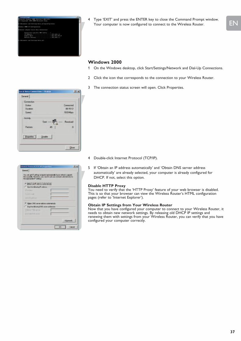
4 Type ‘EXIT’ and press the ENTER key to close the Command Prompt window. Your computer is now configured to connect to the Wireless Router.
Windows 20001 On the Windows desktop, click Start/Settings/Network and Dial-Up Connections.
2 Click the icon that corresponds to the connection to your Wireless Router.
3 The connection status screen will open. Click Properties.
4 Double-click Internet Protocol (TCP/IP).
5 If ‘Obtain an IP address automatically’ and ‘Obtain DNS server addressautomatically’ are already selected, your computer is already configured forDHCP. If not, select this option.
Disable HTTP ProxyYou need to verify that the ‘HTTP Proxy’ feature of your web browser is disabled.This is so that your browser can view the Wireless Router’s HTML configurationpages (refer to ‘Internet Explorer’).
Obtain IP Settings from Your Wireless RouterNow that you have configured your computer to connect to your Wireless Router, itneeds to obtain new network settings. By releasing old DHCP IP settings andrenewing them with settings from your Wireless Router, you can verify that you haveconfigured your computer correctly.

EN
38
1 On the Windows desktop, click Start/Programs/Accessories/Command Prompt.
2 In the Command Prompt window, type ‘IPCONFIG /RELEASE’ and press theENTER key.
3 Type ‘IPCONFIG /RENEW’ and press the ENTER key. Verify that your IP Address is now 192.168.1.xxx, your Subnet Mask is 255.255.255.0 and yourDefault Gateway is 192.168.1.2.
These values confirm that your Wireless Router is functioning.
4 Type ‘EXIT’ and press the ENTER key to close the Command Prompt window.
Your computer is now configured to connect to the Wireless Router.
Windows XP1 On the Windows desktop, click Start/Control Panel.
2 In the Control Panel window, click Network and Internet Connections.
3 The Network Connections window will open. Double-click the connection for this device.
4 On the connection status screen, click Properties.
5 Double-click Internet Protocol (TCP/IP).
6 If ‘Obtain an IP address automatically’ and ‘Obtain DNS server addressautomatically’ are already selected, your computer is already configured forDHCP. If not, select this option.
Disable HTTP ProxyYou need to verify that the ‘HTTP Proxy’ feature of your web browser is disabled.This is so that your browser can view the Wireless Router’s HTML configurationpages (refer to ‘Internet Explorer’).
Obtain IP Settings from Your Wireless RouterNow that you have configured your computer to connect to your Wireless Router, itneeds to obtain new network settings. By releasing old DHCP IP settings andrenewing them with settings from your Wireless Router, you can verify that you haveconfigured your computer correctly.
1 On the Windows desktop, click Start/Programs/Accessories/Command Prompt.
2 In the Command Prompt window, type ‘IPCONFIG /RELEASE’ and press theENTER key.

EN
39
3 Type ‘IPCONFIG /RENEW’ and press the ENTER key. Verify that your IPAddress is now 192.168.1.xxx, your Subnet Mask is 255.255.255.0 and yourDefault Gateway is 192.168.1.2. These values confirm that your Wireless Routeris functioning. Type ‘EXIT’ and press the ENTER key to close the Command Prompt window.
Your computer is now configured to connect to the Wireless Router.
Configuring Your Macintosh ComputerYou may find that the instructions here do not exactly match your operating system.This is because these steps and screen shots were created using Mac OS 10.2. MacOS 7.x and above are similar, but may not be identical to Mac OS 10.2.
Follow these instructions:
1 Pull down the Apple Menu. Click System Preferences.
2 Double-click the Network icon in the Systems Preferences window.
3 If ‘Using DHCP Server’ is already selected in the Configure field, your computer isalready configured for DHCP. If not, select this Option.
4 Your new settings are shown on the TCP/IP tab. Verify that your IP Address isnow 192.168.1.xxx, your Subnet Mask is 255.255.255.0 and your Default Gatewayis 192.168.1.2. These values confirm that your Wireless Router is functioning.
5 Close the Network window.
Now your computer is configured to connect to the Wireless Router.
EN
40
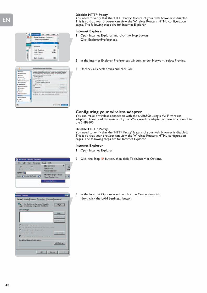
Disable HTTP ProxyYou need to verify that the ‘HTTP Proxy’ feature of your web browser is disabled.This is so that your browser can view the Wireless Router’s HTML configurationpages. The following steps are for Internet Explorer.
Internet Explorer1 Open Internet Explorer and click the Stop button.
Click Explorer/Preferences.
2 In the Internet Explorer Preferences window, under Network, select Proxies.
3 Uncheck all check boxes and click OK.
Configuring your wireless adapter You can make a wireless connection with the SNB6500 using a Wi-Fi wirelessadapter. Please read the manual of your Wi-Fi wireless adapter on how to connect tothe SNB6500.
Disable HTTP ProxyYou need to verify that the ‘HTTP Proxy’ feature of your web browser is disabled.This is so that your browser can view the Wireless Router’s HTML configurationpages. The following steps are for Internet Explorer.
Internet Explorer
1 Open Internet Explorer.
2 Click the Stop button, then click Tools/Internet Options.
3 In the Internet Options window, click the Connections tab. Next, click the LAN Settings... button.
EN
41
MAC addressThe MAC address can be used to prevent unwanted access to your Wireless Router.How to do this is explained in MAC Filter.The MAC address has the format of xx:xx:xx:xx:xx:xx where x can be in the range of[0...9, A...F]
Windows NT4/2000/XPClick Start/Programs/Command Prompt. Type ‘ipconfig /all’ and press ‘ENTER’.
The MAC address is listed as the ‘Physical Address.’
MacintoshClick System Preferences/Network.
The MAC address is listed as the ‘Ethernet Address’ on the TCP/IP tab.
LinuxRun the command ‘/sbin/ifconfig.’
Finding the MAC address of a Network Card
How to set-up a computer network?
The next pages will show you an example of how to set-up a computer networkusing the Philips Wireless Router.
Warning: The Wireless Router only establishes a connection between your wirelessnetwork devices. How you use this connection is up to you.
Setting-up a computer network is to be seen as an independent application thatrequires networking software from other manufacturers. For example, the networking software that has been incorporated in the WindowsOperating System by Microsoft.
Therefore, the description below is to be seen as an example only.
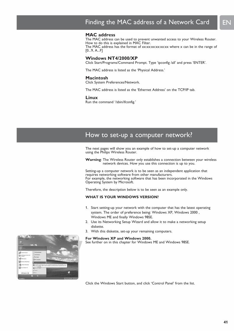
WHAT IS YOUR WINDOWS VERSION?
1. Start setting-up your network with the computer that has the latest operatingsystem. The order of preference being: Windows XP, Windows 2000 ,Windows ME and finally Windows 98SE.
2. Use its Networking Setup Wizard and allow it to make a networking setupdiskette.
3. With this diskette, set-up your remaining computers.
For Windows XP and Windows 2000.See further on in this chapter for Windows ME and Windows 98SE.
Click the Windows Start button, and click ‘Control Panel’ from the list.
EN
42
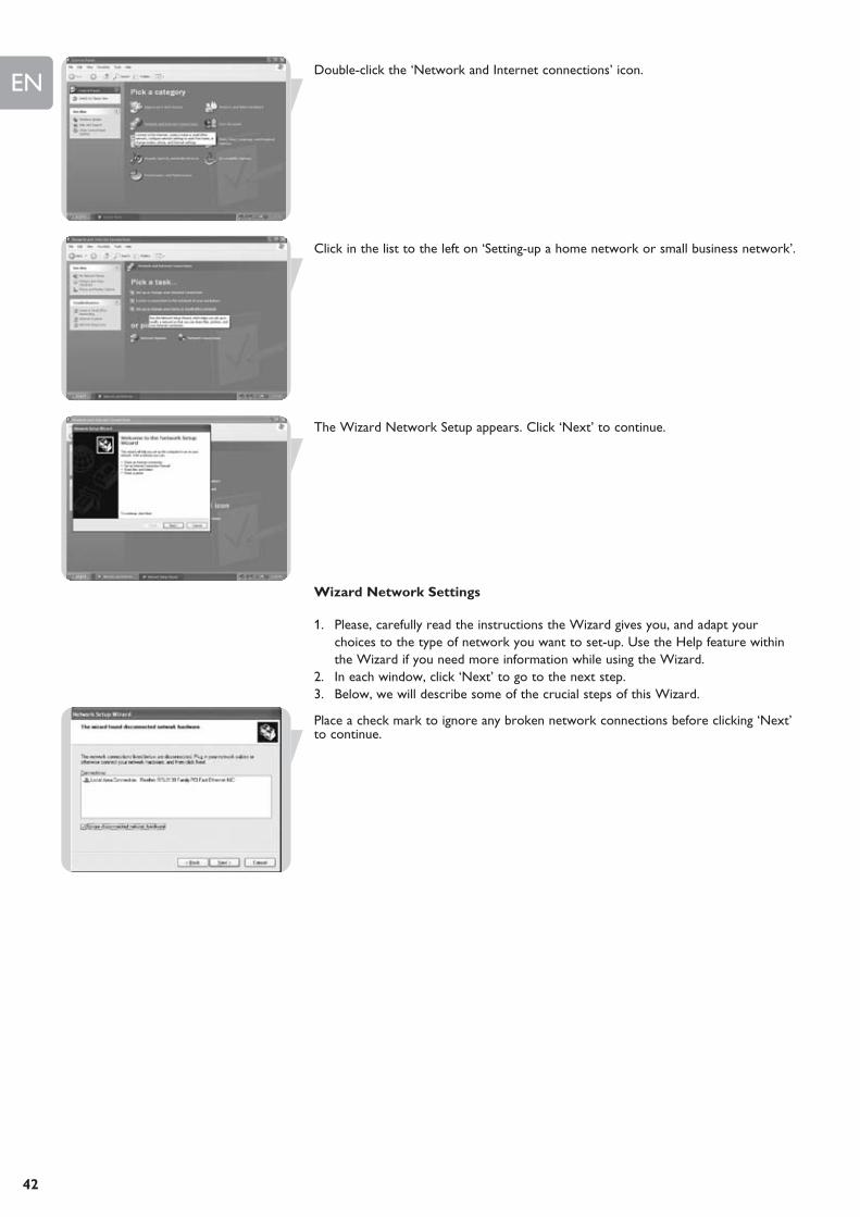
Double-click the ‘Network and Internet connections’ icon.
Click in the list to the left on ‘Setting-up a home network or small business network’.
The Wizard Network Setup appears. Click ‘Next’ to continue.
Wizard Network Settings
1. Please, carefully read the instructions the Wizard gives you, and adapt yourchoices to the type of network you want to set-up. Use the Help feature withinthe Wizard if you need more information while using the Wizard.
2. In each window, click ‘Next’ to go to the next step.3. Below, we will describe some of the crucial steps of this Wizard.
Place a check mark to ignore any broken network connections before clicking ‘Next’to continue.

EN
43
1. Enter a description that helps you recognize the computer.2. Enter a name that is different for each computer.3. Click ‘Next’ to continue.
Enter the same workgroup name for all computers in the network, then click ‘Next’to continue.
Choose to make a networking setup disk. Then click ‘Next’.
Click ‘Finish’ to close the Wizard, and then use the disk you made to set-up yourother computers.
To share folders with the network: Start Windows Explorer and right-click the folderyou wish to share with the network. Click the ‘Sharing’ tab and adapt the settings.
EN
44
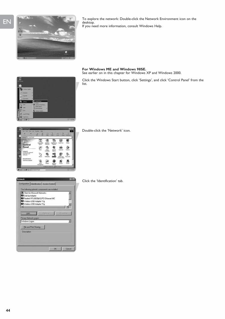
To explore the network: Double-click the Network Environment icon on thedesktop.If you need more information, consult Windows Help.
For Windows ME and Windows 98SE.See earlier on in this chapter for Windows XP and Windows 2000.
Click the Windows Start button, click ‘Settings’, and click ‘Control Panel’ from thelist.
Double-click the ‘Network’ icon.
Click the ‘Identification’ tab.

EN
45
1. Enter a name that is different for each computer.2. Enter the same workgroup name for all computers in the network.3. Enter a description that helps you recognize the computer.4. Click on the ‘Configuration’ tab to continue.
Click the ‘Sharing files and printers’ button.
Select the access options you want, and click ‘OK’ to continue.
EN
46
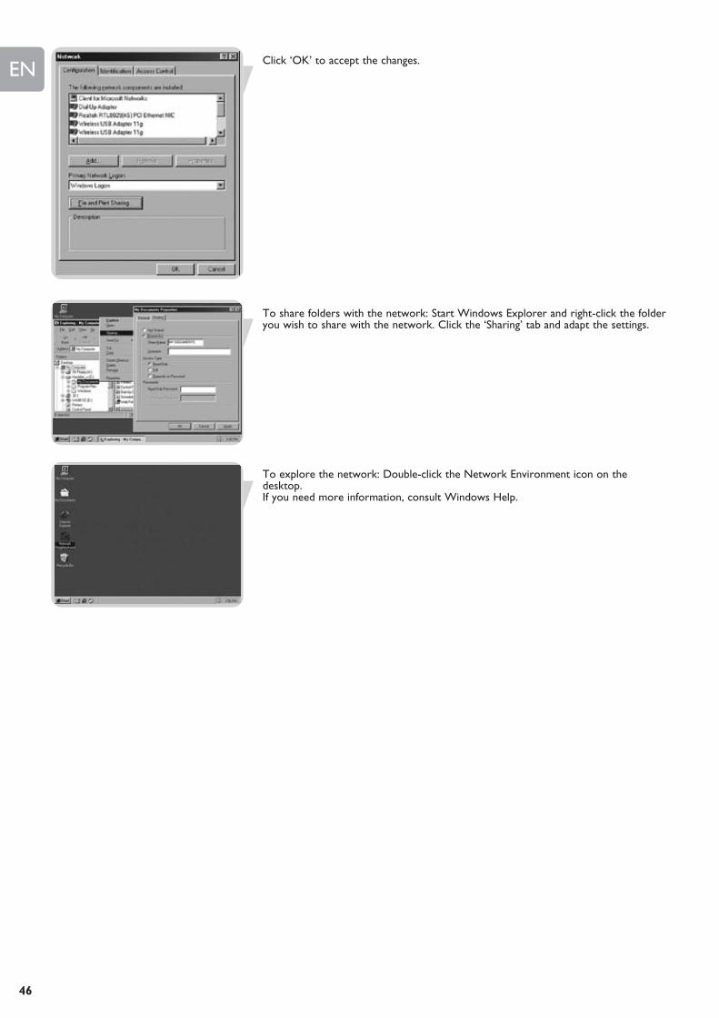
Click ‘OK’ to accept the changes.
To share folders with the network: Start Windows Explorer and right-click the folderyou wish to share with the network. Click the ‘Sharing’ tab and adapt the settings.
To explore the network: Double-click the Network Environment icon on thedesktop.If you need more information, consult Windows Help.
EN
47
Troubleshooting
This section describes common problems you may encounter and possible solutionsto them. The Wireless Router can be easily monitored through panel indicators toidentify problems.
Problem Cause/SolutionI cannot browse to my Your PC did not get an IP address from the Wireless Router.Wireless Router • Verify that your PC has an IP address.
Open a command box (Windows key ‘r’, type cmd, hit enter).Type ipconfig.Check that your gateway address is 192.168.1.2
Your PC can not communicate with your Wireless Router.• Verify that you can communicate with the Wireless Router.
Open a command box.Type ping 192.168.1.2Response should be ‘Reply from 192.168.1.2: bytes=32 time=110ms TTL=32’ (time and TTL could be different)
My PC does not have/get an IP address Network card is not configured to obtain an IP address automatically.• Check if Network Interface Card (NIC) is in DHCP mode.
See chapter ‘Configure your PC’.
Network card speed does not match Wireless Router speed.• Set network adapter to a fixed speed on your computer.
1 Click Start.2 Click Settings.3 Click Network Connections.4 Select you network card. Right mouse click. Select Properties.5 Click Configure.6 Click Advanced tab.
Click Link Speed & Duplex. Select a Full Duplex speed (either 100Mbps or 10Mbps)
Cable between PC and Wireless Router is not connected.• Check Ethernet cable and lights on the Wireless Router.

EN
48
Glossary of terms
DHCP Dynamic Host Configuration Protocol. This protocol automatically configures theTCP/IP settings of every computer on your home network.
DNS Server Address DNS stands for Domain Name System, which allows Internet host computers to havea domain name and one or more IP addresses. A DNS server keeps a database ofhost computers and their respective domain names and IP addresses, so that when adomain name is requested, the user is sent to the proper IP address. The DNSserver address used by the computers on your home network is the location of theDNS server your ISP has assigned.
DSL Modem DSL stands for Digital Subscriber Line. A DSL modem uses your existing phone lines to transmit data at high speeds.
Ethernet A standard for computer networks. Ethernet networks are connected by specialcables and hubs, and move data around at up to 10 million bits per second (Mbps).
HPNA Home Phone Line Networking Alliance, which is an association of corporations(including ) working to ensure the adoption of a single, unified phone line networkingstandard. Your Home Connect home network gateway is compliant with HPNASpecification 2.0, which allows networking speeds of up to 1 million bits per second(Mbps) using your existing home phone lines.
IP Address IP stands for Internet Protocol. An IP address consists of a series of four numbers separated by periods, thatidentifies an single, unique Internet computer host. Example: 192.34.45.8.
ISP Gateway Address The ISP Gateway Address is an IP address for the Internet router located at the (see ISP for definition) ISP’s office. This address is required only when using a cable or DSL modem.
ISP Internet Service Provider. An ISP is a business that provides connectivity to theInternet for individuals and other businesses or organizations.
LAN Local Area Network. A LAN is a group of computers and devices connected together in a relatively smallarea (such as a house or an office). Your home network is considered a LAN.
MAC Address MAC stands for Media Access Control. A MAC address is the hardware address of a device connected to a network.
NAT Network Address Translation. This process allows all of the computers on yourhome network to use one IP address. Using the NAT capability of the HomeConnect home network gateway, you can access the Internet from any computer onyour home network without having to purchase more IP addresses from your ISP.
PPPoE Point-to-Point Protocol over Ethernet. Point-to-Point Protocol is a method of secure data transmission originally created fordial-up connections; PPPoE is for Ethernet connections.
RJ-45 Registered Jack-45, 8 wire connector
Secondary Dial-Up A secondary dial-up phone number is used by your ISP in case your primary dial-upnumber has too many other customers accessing it. The secondary dial-up phonenumber will be used if your primary dial-up phone number cannot be accessed.
SPI Stateful Packet Inspection. SPI is the type of corporate-grade Internet securityprovided by your Home Connect home network gateway. Using SPI, the gateway actsas a “firewall”, protecting your network from computer hackers.
Subnet Mask A subnet mask, which may be a part of the TCP/IP information provided by your ISP,is a set of four numbers configured like an IP address. It is used to create IP addressnumbers used only within a particular network (as opposed to valid IP addressnumbers recognized by the Internet, which must assigned by InterNIC).
TCP/IP Transmission Control Protocol/Internet Protocol. This is the standard protocol for data transmission over the Internet.
WAN Wide Area Network. A network that connects computers located in geographically separate areas, (i.e., different buildings, cities, countries). The Internet is a wide area network.

ENTechnical Specifications
49
Physical Characteristics
Ports– Four 10/100Mbps RJ-45 Ports
Management Features– Firmware upgrade via web based management– Web based management (configuration)– Power indicators– Event and history logging– Network ping
Security Features– Password protected configuration access– User authentication (PAP/CHAP) with PPP– Firewall NAT NAPT– VPN pass through (IPSec-ESP Tunnel mode,L2TP, PPTP)
LAN Features– IEEE 802.1d (self-learning transparent Bridging)– DHCP Server– DNS Proxy– Static Routing, RIPv1 and RIP
Radio Features– Wireless RF module Frequency Band– 802.11g Radio: 2.4GHz– 802.11b Radio: 2.4GHzEurope - ETSI– 2412~2472MHz (Ch1~Ch13)
Modulation Type– OFDM, CCK
Operating Channels IEEE 802.11b compliant:– 13 channels (ETSI)
Operating Channels IEEE 802.11g compliant:– 13 channels (Europe)
RF Output Power Modulation Rate-Output Power (dBm)802.11b - 1Mbps (16 dBm)802.11b - 2Mbps (16 dBm)802.11b - 5.5Mbps (16 dBm)802.11b - 11Mbps (16 dBm)
Modulation Rate-Output Power (dBm)802.11g - 6Mbps (15 dBm)802.11g - 9Mbps (15 dBm)802.11g - 12Mbps (15 dBm)802.11g - 18Mbps (15 dBm)802.11g- 24Mbps (15 dBm)802.11g - 36Mbps (15 dBm)802.11g- 48Mbps (15 dBm)802.11g - 54Mbps (15 dBm)802.11g - 108Mbps (15 dBm)


Specifications are subject to change without notice.Trademarks are the property of Koninklijke Philips Electronics N.V. or their respective owners.
2006 © Koninklijke Philips Electronics N.V. All rights reserved.
www.philips.com
DFU-SNB6500-ENG-V2.0
Guarantee certificateCertificat de garantieGarantiescheinGarantiebewijs
Certificado de garantiaCertificato di garanziaCertificado de garantia∂ÁÁ‡ËÛË
GarantibevisGaranticertifikatGarantibevisTakuutodistus
22
0682
Type: SNB6500
Serial nr: _____________________________________________________________________
Date of purchase - Date de la vente - Verkaufsdatum - Aankoopdatum - Fecha de compra - Date d’acquisito - Data da adquirição - HÌÂÚÔÌËÓía aÁÔÚ¿˜ - Inköpsdatum - Anskaffelsesdato - Kjøpedato - Oatopäivä -
year warrantyannée garantieJahr Garantiejaar garantieaño garantiaanno garanzia
¯ÚfiÓÛ˜ ÂÁÁ‡ËÛËår garantiår garantiår garantivuosi takuuaño garantia
Dealer’s name, address and signatureNom, adresse et signature du revendeurName, Anschrift und Unterschrift des HändlersNaam, adres en handtekening v.d. handelaarNombre, direccion y firma del distribudorNome, indirizzo e firma del fornitore
√ÓÔÌaÙÂÒÓÌÔ, ‰È‡ı˘ÓÛË ÎaÈ ˘ÔÁÚaÊË ÙÔ˘ ÂÌ. ÚÔÌËı¢ÙË
Återförsäljarens namn, adress och signaturForhandlerens navn, adresse og unterskriftForhandlerens navn, adresse og unterskriftJälleenmyyjän nimi, osoite ja allekirjoitusNome, morada e assinature da loja