sndice: a calibrated multi-wavelength light source for ...ins/2010calworkshop/schahmaneche.pdf ·...
TRANSCRIPT

The 2010 STScI Calibration WorkshopSpace Telescope Science Institute, 2010Susana Deustua and Cristina Oliveira, eds.
SNDICE: A Calibrated Multi-Wavelength Light Source for OpticalTelescope Calibration with a Stability and a Precision of 10!4
K. Schahmaneche, for the SNDICE Collaboration(http://supernovae.in2p3.fr/sndice)
LPNHE, CNRS-IN2P3 and Universites Paris 6 & 7, 4 place Jussieu, F-75252Paris Cedex 05, France
Abstract.Cosmological topics such as the study of Dark Energy, require a better photo-
metric precision than what has been achieved until now. An accuracy better than1% is at least necessary. To go in that direction, we have designed, constructed andinstalled at the Canada-France-Hawai’i Telescope (CFHT), a calibrated light source.The goal is to monitor and calibrate MegaCam, a wide field imager used by projectssuch as the CFHT Legacy Survey and the Supernova Legacy Survey (SNLS). Theaim is to obtain an accuracy better than 0.1%.
1. Introduction
The need for a precise photometric calibration has grown over the last few years. Severalprojects, such as the measurement of the Dark Energy Equation of State using type Iasupernovae, have now reached a point where the precision of the photometric calibrationmust be better than one percent [Astier06]. Usual astrophysical calibration proceduresrelying on standard star observations [Regnault09] are limited by the knowledge of theemission spectra of the reference standards (Vega or the HST white dwarf calibrators1).More precisely, since the cosmological parameters are measured by comparing fluxes ofnearby supernovae (measured in the blue bands of the imagers, around 400nm) to fluxes ofhigh redshift supernovae (measured in the red, around 800nm), it is necessary to control theinter-calibration between the imager passbands. Instrumental devices have been developedto study, monitor and model the transmission curves of the astronomical detectors (telescope+ camera) with a precision of the order of one per-thousand (Stubbs07, Doi10, Stubbs10).In this paper, we present a similar device called SNDICE (SuperNovae Direct IlluminationCalibration Experiment) based on the concept of the direct illumination of the instrumentby LEDs, whose emitted light can be controlled with a precision of about 10!4. Theopportunity o!ered by the progress of LED technologies for supporting CCD photometrywas underlined in a first paper which described SNDICE-type systems [Juramy08]. The lightbeams emitted by these LEDs are monitored by photodiodes located along the light path.The device is calibrated on a precision test bench with respect to a NIST photodiode. TheSNDICE project was initiated in the Spring 2007 and was installed at CFHT in February2008 in order to test the concept, and eventually cross-calibrate the pass-bands of theMegaCam wide field imager (Boulade03). We present here first results obtained with thisprototype.
The calibrated source is described elsewhere [Juramy08]. Its main features (Figure 1)are listed below:
1http://www.stsci.edu/hst/observatory/cdbs/calspec.html and references therein.
121

122 Schahmaneche for the SNDICE Collaboration
Figure 1: SNDICE: the LEDs head (on the left) and the CLAP system (on the right). Thetwo devices are not at the same scale: the LEDs head is 25 cm long and the CLAP 13 cm.
• Light is produced by 24 LEDs whose central wavelength sample the full bandwidth ofMegaCam. The bandwidth of each LED is between 7% and 9% of the central value.A source of current with a precision of 10!5 allows to achieve comfortably a stabilityof the light beam better than 10!4.
• Due to the “flat-top” design of the selected LEDs, the emitted LED beam is anisotropic beam. Using a series of two consecutive masks, the resulting conical beam,after reflection on CFHT primary mirror, covers the entire field of view of MegaCam.
• Redundant control measurements to monitor the stability of the calibrated light sourceare also performed. The current flowing through the LEDs is measured (sampled ata frequency of 30kHz). For each LED, the light emitted is controlled at the output ofthe LEDs source (i.e. 25cm after the LED) by o!-axis control photodiodes. Anotherdevice, located close to the focal plane, a few centimeters from the MegaCam CCDs,permits to monitor the LED light flux. Since this detector must be as sensitive as theCCDs which equip MegaCam, we designed a Cooled Large Area Photodiode (CLAP),which consists in a two-level micro-cryostat encapsulating a 1 cm2 photodiode andcontinuated by an ultra-low current amplifier ASIC. The whole device is small enoughto be placed inside MegaCam.
2. Bench calibration of SNDICE
The LED source was calibrated on a precision bench at LPNHE (Paris). The calibrationwas transferred from an NIST photodiode to the LED light beams. The calibration wasthen transferred to the CLAP. This calibration procedure was performed in two steps.A “spectrometric” calibration was obtained using a monochromator to measure the LEDspectra at fixed currents (the ones to be used at CFHT for MegaCam calibration). A“photometric” calibration was then performed by mapping each LED light field at di!erentdistances from the LED, using a small area calibrated photodiode delivered by Gigaherz-Optik (Figure 2).
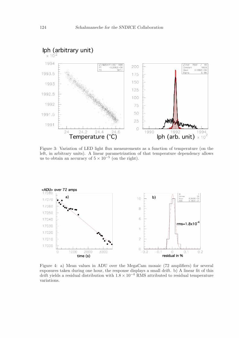
During this calibration procedure, we studied the stability of the LED light beams. Themain variations were found to be due to thermal e!ects. A first study of this e!ect showsthat the variation of the LED spectra can be modeled as a function of the temperature witha simple linear law at an accuracy of 2.5 ! 10!4. A similar first order linear modeling of

SNDICE, First Results 123
Figure 2: Calibration bench measurements: LED beam map measured by a calibratedphotodiode at a given distance of the emitting LED (on the left) and LEDs spectra (on theright). All these measurements were performed with LED currents used for operations atCFHT.
thermal e!ects on the LED light map allowed us to obtain an accuracy on these maps of5 ! 10!5.
3. SNDICE beam quality at CFHT
The SNDICE device (LED light source and the CLAP module) was installed in Hawaii inFebruary 2008. The CLAP module, first located close to the primary mirror, was installedin August 2008 just in front of MegaCam filters.
MegaCam images taken under LED illumination display a high reproducibility. At thepixel scale, for an illumination corresponding to approximately 10000 ADU (for 5 secondsexposure time and an electronic gain around 2), the fluctuations observed between two im-ages taken back to back is slightly larger than the photon noise, and is around 1%. Themean flux measured on a larger scale, namely on 128x128 superpixels, shows a reproducibil-ity down to 10!4.
For longer time intervals between exposures, around one hour, one can measure adecrease of the flux measured by MegaCam. This e!ect of a few per thousand is due tothermal variations: MegaCam calibration runs are done during day-time, in the morningand the ambient temperature generally increases during the run. This implies an expectedvariation of the LED light flux. Introducing a simple linear parametrization of this e!ectreduces the dispersion of the global LED light flux measured by MegaCam at 1.8 ! 10!4
(Figure 4).A first longer time scale analysis, over 4 month in 2010 (4 SNDICE calibration runs
from March to July) shows a stability of the response of MegaCam to SNDICE illuminationbetter than 0.5% (Figure 5).
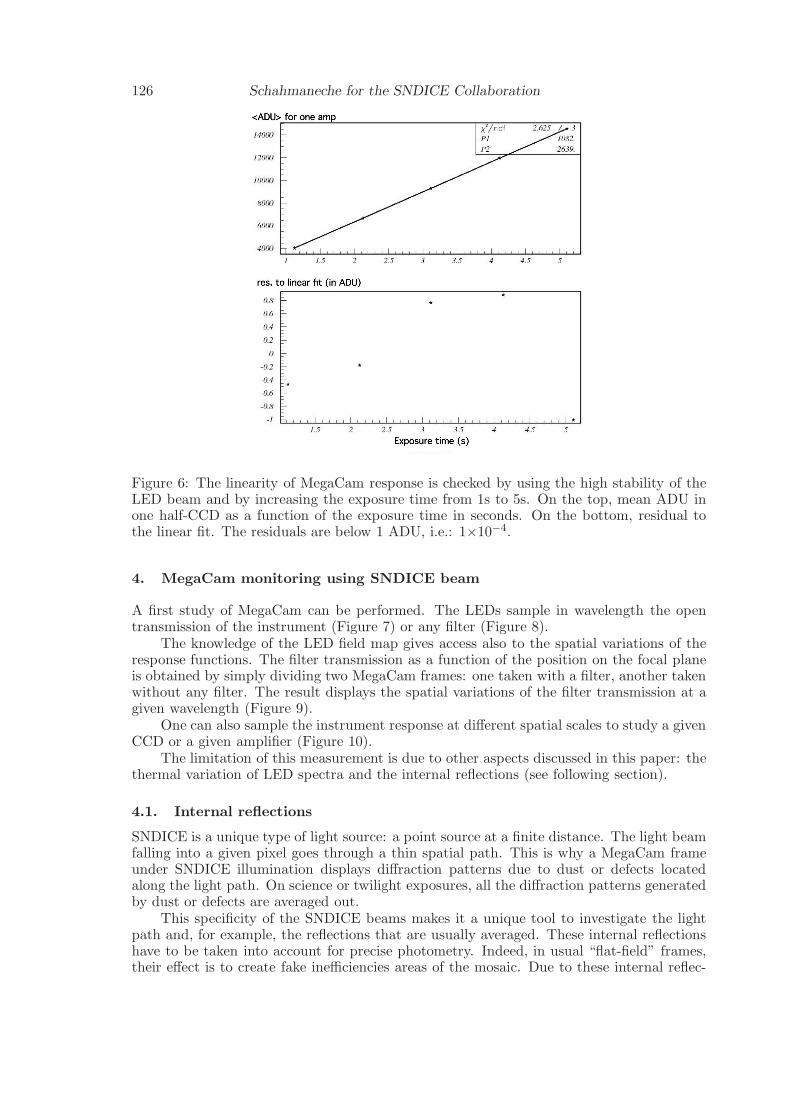
We finish this stability study with a linearity test. By increasing MegaCam exposuretimes from 1s to 5s, we can check the linearity of the response of the imager in the illumi-nation range [from 3000 ADU / pixel to 13000 ADU / pixel], using the high stability of theLED light source (Figure 6). The residuals to the linear fit are all below 0.01%.
124 Schahmaneche for the SNDICE Collaboration
Figure 3: Variation of LED light flux measurements as a function of temperature (on theleft, in arbitrary units). A linear parametrization of that temperature dependency allowsus to obtain an accuracy of 5 ! 10!5 (on the right).
Figure 4: a) Mean values in ADU over the MegaCam mosaic (72 amplifiers) for severalexposures taken during one hour, the response displays a small drift. b) A linear fit of thisdrift yields a residual distribution with 1.8! 10!4 RMS attributed to residual temperaturevariations.

SNDICE, First Results 125
Figure 5: Mean values in ADU for one MegaCam amplifier as a function of MJD for severalcalibration runs at CFHT (circles). The drift is due to seasonal thermal variations. Bytaking into account the thermal dependency we are able to reduce the dispersion below5 ! 10!3 (black stars).
126 Schahmaneche for the SNDICE Collaboration
Figure 6: The linearity of MegaCam response is checked by using the high stability of theLED beam and by increasing the exposure time from 1s to 5s. On the top, mean ADU inone half-CCD as a function of the exposure time in seconds. On the bottom, residual tothe linear fit. The residuals are below 1 ADU, i.e.: 1!10!4.
4. MegaCam monitoring using SNDICE beam
A first study of MegaCam can be performed. The LEDs sample in wavelength the opentransmission of the instrument (Figure 7) or any filter (Figure 8).
The knowledge of the LED field map gives access also to the spatial variations of theresponse functions. The filter transmission as a function of the position on the focal planeis obtained by simply dividing two MegaCam frames: one taken with a filter, another takenwithout any filter. The result displays the spatial variations of the filter transmission at agiven wavelength (Figure 9).
One can also sample the instrument response at di!erent spatial scales to study a givenCCD or a given amplifier (Figure 10).
The limitation of this measurement is due to other aspects discussed in this paper: thethermal variation of LED spectra and the internal reflections (see following section).
4.1. Internal reflections
SNDICE is a unique type of light source: a point source at a finite distance. The light beamfalling into a given pixel goes through a thin spatial path. This is why a MegaCam frameunder SNDICE illumination displays di!raction patterns due to dust or defects locatedalong the light path. On science or twilight exposures, all the di!raction patterns generatedby dust or defects are averaged out.
This specificity of the SNDICE beams makes it a unique tool to investigate the lightpath and, for example, the reflections that are usually averaged. These internal reflectionshave to be taken into account for precise photometry. Indeed, in usual “flat-field” frames,their e!ect is to create fake ine"ciencies areas of the mosaic. Due to these internal reflec-

SNDICE, First Results 127
Figure 7: MegaCam open transmission (no filter) sampled with all LEDs. This is a relativemeasurement: a global coe!cient was used to adjust the measurement for the ”central”LED (! = 600 nm).
Figure 8: MegaCam u!, g", r", i", z" sampling with LEDs. The filters’ transmission curves arethe ones delivered by the constructor (REOSC-SAGEM).

128 Schahmaneche for the SNDICE Collaboration
Figure 9: Comparison of the spatial variations of g! filter transmission for several LEDwavelength: SNDICE measurement (top), simulation based on the constructor (REOSC-SAGEM) data (bottom). The central ine!ciency is a well known feature of the MegaCamg! filter. For the highest wavelength it is compensated by a central higher e!ciency.
tions, ”flat-field” frames are polluted and in turn a"ect the uniformity of the photometryof astrophysical sources.
For example, one can easily see a pincushion pattern on some MegaCam/SNDICEframes showing the reflection of the beam on the CCD plane or on the filter, if there is one,then again on the last surface of the Wide Field Corrector located in front of MegaCamand composed of 4 lenses (Figure 11).
To study more precisely these reflections, a central LED channel, initially designed forSNDICE-MegaCam geometrical alignment (called the “planet” channel because, contraryto the other LEDs, its illumination gives only a spot a few thousand pixels wide), is anextremely e!cient tool for reflections investigation. The MegaCam/SNDICE frames takenwith this specific channel provide unique data to fine tune an optical simulation of theinstrument (Figure 12).
4.2. Surfaces studies
The di"raction pattern caused by dust or defects along the light path can be used to studythe di"erent surfaces encountered by the SNDICE beam.
The CCDs can be illuminated by the same SNDICE light field but with di"erent relativepositions of SNDICE with respect to the telescope (i.e.: di"erent “impact parameters” ofthe optical axis of the LED light beam w.r.t. the optical axis of the telescope). Using thispossibility, one can “track” the same di"raction pattern in di"erent illumination positions,and deduce from this the optical surface where the defects or dust grains are located (Figures13). This has been done by showing the accumulation of dust/defects on the di"erent opticalsurfaces of the Wide Field Corrector or on the primary mirror (Figure 14).

SNDICE, First Results 129
Figure 10: Mean e!ective gain (electronics gain times CCD QE at !LED) for 72 amplifiersmeasured using SNDICE LEDs (arbitrary units).
Figure 11: Evidence for Fresnel reflection on a MegaCam image (whole mosaic) obtainedunder LED beam (on the left) and its simulation using ray tracing (on the right).

130 Schahmaneche for the SNDICE Collaboration
Figure 12: Spot generated by the specific alignment ”planet” channel (on the left with alinear grey-scale). Multiple reflections of this spot are visible on a log colored-scale (on theright). This special channel is unique to ray trace testing.
Figure 13: Surface defects on the mirror or any lens of the Wide Field Corrector, generatedi!raction patterns on the focal plane. The location of these patterns varies with thegeometrical relative position of SNDICE w.r.t. telescope axis. By changing this positionone can locate the defect in the optical path.

SNDICE, First Results 131
Figure 14: The distribution of the ”displacement” (measured in superpixels = 16x16 pixels)of the di!raction pattern on the frame shows peaks corresponding to the di!erent surfaceswhere the defects are located. The main peak corresponds to defect/dust accumulated onthe primary mirror. The two other peaks correspond to shorter ”displacement” and soshorter distance of the di!raction source w.r.t. the focal plane, i.e., correspond to both ofthe extreme optical surfaces of the Wide Field Corrector located just in front of MegaCam.
5. Actual limitations of this first prototype
The thermal variations measured on the calibration bench at LPNHE, span a temperaturerange of a few degrees (from 16oC to 24oC). These measurements showed that it not possibleto extrapolate our calibration measurements (spectra and light mapping) to the CFHTdome temperatures (close to 0oC) with a su"cient precision. Instead of extrapolating, it isnecessary to interpolate and to do so, to calibrate the LEDs light in the temperature rangeof their utilization in situ. This is under development: we are modifying the calibrationbench to be able to cool it down to 0oC.
Another limitation is due to the internal reflections showed previously. Using SNDICEspecific alignment channel (the “planet”) we will be able to check a fine tuned model of thetelescope optics by taking into account these reflections and modeling the SNDICE beam.
At the moment, SNDICE is not yet used as an absolute calibrated light source. Once thetwo developments mentioned above will be achieved, we will have an absolutely calibratedlight source in hand.
6. Conclusion
We have shown that SNDICE can be calibrated with a precision better than 10!4 in the lab.In the MegaCam environment, we could measure a short term reproducibility of the Mega-Cam response at 10!4. This gives access to a precise relative calibration and monitoring ofMegaCam at CFHT.
Improvements of our calibration bench (to parametrize precisely flux and spectral vari-ations due to thermal variation) and improvements in the SNDICE beam simulation (to

132 Schahmaneche for the SNDICE Collaboration
take into account reflections on the di!erent MegaCam surfaces) will lead to an absolutecalibration of MegaCam on CFHT.
In addition to the calibration of MegaCam at CFHT, we are currently designing asecond generation device for the wide field imager SkyMapper (Siding Spring Observatory,NSW, Australia).
References
Astier, P. et al., 2006, A&A, 447, 31
Barrelet, E., Juramy, C., 2008, Nuclear Inst. and Methods in Physics Research, A 585,93-101
Boulade, O., Charlot, X., Abbon, P., et al. 2003, SPIE - Instrument Design and Performancefor Optical/Infrared Ground-based Telescopes, Vol. 4841, 72-81
Doi, M., et al., 2010, The Astronomical Journal, 139, 1628
Juramy, C., Barrelet, E., & Schahmaneche, K., 2008, SPIE - Ground-based and airboneinstrumentation for astronomy II, Vol. 7014
Regnault, N., 2009, A&A, 506, 999
Stubbs, C. et al., 2007, Publications of the Astronomical Society of the Pacific, Vol. 19,1163, 1178
Stubbs, C. et al., 2010, SPIE - Modern Technologies in Space- and Ground-based Telescopesand Instrumentation, Vol. 119