snow melt mats - delta-therm corporation · 1 delta-therm corporation 6dqgv5g6wh$&u\vwdo/dnh ,/...
TRANSCRIPT

1DELTA-THERM Corporation, 6711 Sands Rd Ste A Crystal Lake, IL 60014 (847) 526-2407 Fax (847) 526-4456 (800) 526-7887
Installation Instructions
Snow Melt MatS
Contents pageseCtIon 1. Overview
1.1 Precautions .................................................................................... 236 1.2 Mat and components ..................................................................... 2361.3 General accessories ..................................................................... 236 1.4 Tools recommended ...................................................................... 2361.5 Site plan ........................................................................................ 236 1.6 Mat storage .................................................................................. 2361.7 Mat labeling .................................................................................. 236 1.8 Mat testing .................................................................................... 236 1.9 Site preparation ............................................................................. 2371.10 Proper mat handling .................................................................... 2371.11 N.e.C. code .................................................................................. 2371.12 Conduit and circuit wire ............................................................... 237
seCtIon 2. iNSTALLATiON2.1 General information ...................................................................... 2382.2 Slabs: concrete ............................................................................. 2392.3 Slabs: asphalt ............................................................................... 2402.2 Stairs: concrete ............................................................................. 241
seCtIon 3. TeSTiNG ANd TrOubLe-ShOOTiNG3.1 Pre-installation testing ................................................................... 2423.2 Monitoring during installation ........................................................ 2423.3 Final testing................................................................................... 2423.4 Trouble-shooting and technical support ....................................... 242
warning: Snow melt mats must be installed by a qualified electrician. All assembly, installation, and test instructions must be followed. improper installation can result in property damage, serious injury, or death due to electric shock. dO NOT ShOrTeN heATer LeNGTh. Please call delta-Therm Corporation at 1-800-526-7887 with any installation or operating questions.
DELTA-THERM Corporation, 6711 Sands Rd Ste A Crystal Lake, IL 60014 (847) 526-2407 Fax (847) 526-4456 (800) 526-7887
2
1.1 PreCautIons
1.2 snoW MeLtInG Matand CoMPonents
1.3 GeneraL aCCessorIes
1.4 tooLs reCoMMended
1.5 sIte PLan
1.6 Mat storaGe
1.7 Mat LabeLInG
1.8 Mat testInG
Section 1. overview• install in accordance with the National electrical Code and local electrical codes.
• do not run mats through expansion joints.
• do not place mats over existing expansion or construction joints.
• do not energize the mats until the concrete has thoroughly cured.
• do not allow workers to walk on mats at any time.
• Test the mat before installation with a 500 vdC insulation resistance tester and multi-meter (ohm meter).
• do not overlap snow melting mats.
• All related components and controls should be properly rated for the specified locationclassification.
• do not alter the snow melting mat cable length in the field, as this will damage thesystem and void all warranties.
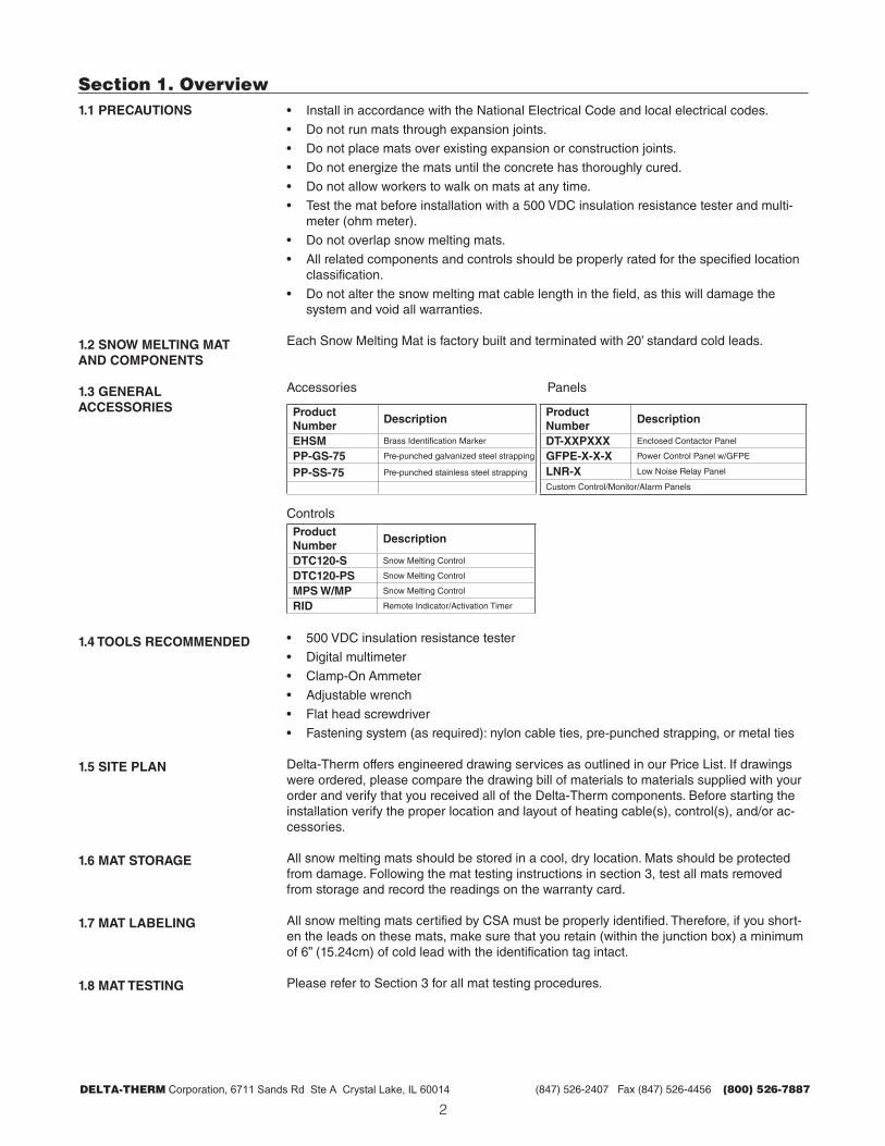
each Snow Melting Mat is factory built and terminated with 20’ standard cold leads.
Accessories Panels
Product number
descriptionProduct number
description
eHsM brass identification Marker dt-XXPXXX enclosed Contactor Panel
PP-Gs-75 Pre-punched galvanized steel strapping GFPe-X-X-X Power Control Panel w/GFPe
PP-ss-75 Pre-punched stainless steel strapping Lnr-X Low Noise relay Panel
Custom Control/Monitor/Alarm Panels
ControlsProduct number
description
dtC120-s Snow Melting Control
dtC120-Ps Snow Melting Control
MPs W/MP Snow Melting Control
rId remote indicator/Activation Timer
• 500 vdC insulation resistance tester
• digital multimeter
• Clamp-On Ammeter
• Adjustable wrench
• Flat head screwdriver
• Fastening system (as required): nylon cable ties, pre-punched strapping, or metal ties
delta-Therm offers engineered drawing services as outlined in our Price List. if drawings were ordered, please compare the drawing bill of materials to materials supplied with your order and verify that you received all of the delta-Therm components. before starting the installation verify the proper location and layout of heating cable(s), control(s), and/or ac-cessories.
All snow melting mats should be stored in a cool, dry location. Mats should be protected from damage. Following the mat testing instructions in section 3, test all mats removed from storage and record the readings on the warranty card.
All snow melting mats certified by CSA must be properly identified. Therefore, if you short-en the leads on these mats, make sure that you retain (within the junction box) a minimum of 6” (15.24cm) of cold lead with the identification tag intact.
Please refer to Section 3 for all mat testing procedures.
DELTA-THERM Corporation, 6711 Sands Rd Ste A Crystal Lake, IL 60014 (847) 526-2407 Fax (847) 526-4456 (800) 526-7887
3
1.9 sIte PreParatIon
1.10 ProPer Mat HandLInG
1.11 n.e.C. Code
1.12 ConduIt and CIrCuIt WIre
Section 1. overviewreview installation, engineering, electrical, and or architectural drawings prior to installa-tion. verify that available voltage is the same as the mat operating voltage indicated on the mat label. install conduit from the cable feed points to an indoor or dry junction box, con-tinuing to the power panel per site plan. install appropriate grounding system per electrical code.
Cap or plug all conduit openings temporarily before installing the snow melting mat, ensure that all surfaces which the mat may come in contact with are free from sharp edges and protect cable from items that may cut or cause damage.
Mat spacing is the distance between each mat and is provided on the sales information and/or drawings. Measure and plan the area to be heated by snow melt mats, allowing for obstructions such as light poles, columns, and drains. in some areas, you may need to shape mats around curves and obstacles. To do so, cut mats between cable loops to suit. do not cut the heating cable.
Always unroll the snow melting mat.
National electrical Code for snow melting mats can be found in Article 426-20.
Please consult NeC Article 426 Fixed Outdoor electric deicing and Snow-Melting equip-ment with attention to:
Section 426.20 embedded deicing and Snow-Melting equipment.
Section 426-13 identification The presence of outdoor electric deicing and snow-melting equipment shall be evident by the posting of appropriate caution signs or markings where clearly visible.
The mats require a permanently wired and grounded conduit system. use only uL Listed (CSA Certified) weatherproof junction boxes.

DELTA-THERM Corporation, 6711 Sands Rd Ste A Crystal Lake, IL 60014 (847) 526-2407 Fax (847) 526-4456 (800) 526-7887
4
2.1 GeneraL InForMatIon
Section 2. electrical Rough-In and testing Proceduresbefore starting the installation please refer to Section 1.5 Site Plan, Section 1.9 Site Prepa-ration, and test cables following the directions in Section 3.1 Pre-installation Testing. if you don’t have a site plan you can make your own layout.
The ideal location for junction boxes is indoors with at least 18” (45.72cm) of accessible mat leads. when you plan the location of junction boxes, allow for at least one foot of mat lead to remain embedded. Locate junction boxes so that they can accommodate the maxi-mum number of mats. use bushings to protect the wire from abrasion where it enters and exits the conduit.
if you must locate junction boxes outdoors, locate them above grade. The junction boxes must be uL listed or CSA certified for rain tight applications. if you must place junction boxes below grade, or in the pavement, use only watertight junction boxes recommended by the box manufacturer. Fill all below-grade junction boxes with delta dry or equivalent.
SILICONEJACKET CABLE
MAT MATERIAL
COLD LEADS
2/2/12SCALE:SM3 PLAN - SNOW MELT MAT
NTS
SILICONEJACKET CABLE
MAT MATERIAL
COLD LEADS
SLAB SENSOR
REMOVE ORANGE MESHUNDER SENSOR
2/2/12SCALE:SM4 PLAN - SNOW MELT MAT
NTS
detail 1. Snow melting mat.
detail 2. Snow melting mat with a slab sensor.

DELTA-THERM Corporation, 6711 Sands Rd Ste A Crystal Lake, IL 60014 (847) 526-2407 Fax (847) 526-4456 (800) 526-7887
5
2.2 sLabs: ConCrete
Section 2. Installationbefore installing mats in concrete determine the location of expansion joints. do not run mats through expansion joints. doing so can damage cable due to concrete movement. Al-low 2” to 4” (5.08 to 10.16cm) on each side of the mats for clearance. Allow approximately 4” (10.16cm) between adjacent mats at expansion joints.
embed mats 2” to 3” (3.81 to 8.89cm) below the finished surface according to the National electrical Code, Article 426-20. For a brick paver top, embed mats in concrete no less than 1.5” and no more than 3” (3.81 no more than 7.62cm) below the paver top. use a winter formulation for concrete in freezing weather.
1. Feed mat cold leads through conduit stubs and bushings into junction box(es). usecaution when pulling cold leads. excessive force could damage the hot-cold splice.
2. Position the mats temporarily according to plan to verify placement and fit. (do notallow workers to walk on mats at any time.)
3. roll up mat allowing the concrete base slab to begin to be poured.
4. Pour concrete to within 2” (5.08cm) of the finish level and roll mat over wet concrete. Then complete the pour and finish the surface. each slab area within expansion jointsshould be individually poured and finished.
5. when the slab can be walked on, make splices within the junction boxes and installthe feeder lines. Twist together a length of the copper grounding braid from all leadsand positively connect to a continuous No. 14 AwG or larger insulated copper wireextending to the distribution panel ground.
6. Secure all splices with approved, pressure-crimped connectors or set-screw-type wir-ing clamps. Thoroughly tape all power splices with plastic electrical tape. All connec-tions in below-grade junction boxes must be protected with delta dry or equivalent.
do not energize the mats until the concrete has thoroughly cured.
CONCRETE BELOW MAT
INSULATION (OPTIONAL)
CONCRETE SLAB
SNOW MELTING MAT2"-3" BELOW SURFACE
GRAVEL BASE (COMPACTED)
UNDISTURBED EARTH
2/2/12
SNOW MELTING MAT ATTACHED TO REBAR IN A SINGLE POUR CONCRETE SYSTEM.
SCALE:SM12 SINGLE-POUR CONCRETE SECTION
NTS
detail 3. Snow melting mat installed in dual pour concrete.

DELTA-THERM Corporation, 6711 Sands Rd Ste A Crystal Lake, IL 60014 (847) 526-2407 Fax (847) 526-4456 (800) 526-7887
6
Section 2. Installation
1.5” ASPHALT BASE BELOW MAT
INSULATION (OPTIONAL)
ASPHALT COVER
SNOW MELTING MAT2"-3" BELOW SURFACE
GRAVEL BASE (COMPACTED)
UNDISTURBED EARTH
2/2/12
SNOW MELTING MAT ATTACHED TO REBAR IN A SINGLE POUR CONCRETE SYSTEM.
SCALE:SM12 SINGLE-POUR ASPHALT SECTION
NTS
detail 4. Snow melting mat installed in dual pour asphalt.
2.2 sLabs: asPHaLt Prepare an adequate base. ensure adequate drainage to prevent accumulation of water and resultant heaving (frost damage). if you see signs of cracking or heaving in the exist-ing pavement, replace the pavement or apply a full base course before placing the mats.
before installing mats in asphalt select the largest mats which can be used on the straight runs. Place mats 6” to 12” (15.24 to 30.48cm) in from the pavement edge. do not overlap adjacent mats since doing so may cause excessive temperatures.
embed mats 2” to 3” (3.81 to 8.89cm) below the finished surface according to the National electrical Code, Article 426-20.
1. Feed mat cold leads through conduit stubs and bushings into junction box(es). usecaution when pulling cold leads. excessive force could damage the hot-cold splice.
2. use as fine a grade of asphalt as possible for top course. Gravel should not exceed a.375” (9.65mm) diameter.
3. Lay and roll the base course, then apply a coat of bituminous binder.
4. Position the mats according to plan, then apply a coat of binder over them. if youplace the mats on an existing surface, be sure to sweep it thoroughly to remove anysharp material that could puncture cables during the installation. ensure that coldleads are positioned at or below mat level. do not allow workers to walk on mats.
5. Lay the 2” (5.08cm) top coat, covering the entire mat in one continuous slab. roll thetopcoat. Take insulation resistance test and ohmmeter readings on each mat duringand after the roll to check for installation damage.
6. when raking and spreading the asphalt, ensure that you do not damage mats or dis-turb their position. do not use spades or steel shovels since they can cut cables. rollpaved area with any size power roller. Never stop the roller on a grade while compact-ing the second course. doing so could cause asphalt to slide, thereby damaging mats.
7. Complete all electrical connections.
8. do not energize the mats until the asphalt has hardened.

DELTA-THERM Corporation, 6711 Sands Rd Ste A Crystal Lake, IL 60014 (847) 526-2407 Fax (847) 526-4456 (800) 526-7887
7
Section 2. Installation2.2 staIrs: ConCrete embed mats 2” to 3” (3.81 to 8.89cm) below the finished surface according to the National
electrical Code, Article 426-20. do not allow mat to cross expansion joints.
1. Feed mat cold leads through conduit stubs and bushings into junction box(es). usecaution when pulling cold leads. excessive force could damage the hot-cold splice.
2. Tempoarily position the mats 1”-2” in from the stair edge. Position according to planto verify placement and fit in stair tread. (do not allow workers to walk on mats at anytime.)
3. roll up mat allowing the concrete base slab to be poured.
4. Pour concrete to within 2” (5.08cm) of the finish level and roll mat over wet concrete. Then complete the pour and finish the surface. each slab area within expansion jointsshould be individually poured and finished.
5. Complete all electrical connections.
6. do not energize the mats until the concrete has thoroughly cured.
NOTe: if slab sensor is to be installed in the stairs, it must be installed in a heated area.For hand rails; please sleeve or locate of handrail attachment points so as not to damage mats when hand rails installed..
3/6/12SCALE:SM49 PLAN - STAIR SM MATS
NTS
detail 5. Step snow melting mats are custom sized for the stair tread.

DELTA-THERM Corporation, 6711 Sands Rd Ste A Crystal Lake, IL 60014 (847) 526-2407 Fax (847) 526-4456 (800) 526-7887
8
Section 3. testing and trouble Shooting 3.1 Pre-InstaLLatIon testInG
3.2 MonItorInG CabLe durInG InstaLLatIon
3.3 FInaL testInG
3.4 troubLe-sHootInG and teCHnICaL suPPort
unpack the snow melting mats and test each mat for insulation resistance (ir), and total resistance (Tr).
To test Tr, connect one lead of the ohmmeter to one cable cold lead center conductor and connect the other lead of the ohmmeter to the other cold lead center conductor. Test in ac-cordance with the meter manufacturer’s instructions. Compare Tr reading from ohmmeter to calculated Tr (check the table below). The ohmmeter reading should be within 10% of the calculated Tr.
To test ir, connect one lead of the 500 vdC insulation resistance tester to one cold lead conductor and the other lead to the cold lead copper braid. Test in accordance with the meter manufacturer’s instructions. ir reading should be greater than 10 megohms.
Please enter the Tr and ir readings on the warranty card.
repeat the steps as described in Section 3.1 and enter the information on the warranty card. if there is a change in the meter reading, please check the cable for damage, as well as any power connections, splices, and end terminations.
repeat the Tr and ir test steps as described in Section 3.1. enter the information on the warranty card. if there is a change in the meter reading, please check the cable for dam-age, as well as any power connections, splices, and end terminations.
if during any test the meter readings vary by +/- 10% from the previous test, stop the instal-lation and investigate. Please check for pinched or crushed cables, test splices, test power connections, test end terminations, and repair accordingly. Check for water in all junction boxes or conduit. Any faults should be repaired by a qualified electrician or factory techni-cian before the final pour is made.
For additional trouble-shooting and repair procedures, please contact delta-Therm techni-cal support at 1-800-526-7887. Please be prepared to provide:
• Part numbers for all installed equipment
• ir and Tr readings on all installed mats
• verification that incoming voltage matches design voltage of delta-Therm equipment
• verification that you have checked all wiring, junction boxes, etc.
• digital photos of installed equipment
if you have any questions or comments about these instructions or your installation please call delta-Therm at 1-800-526-7887.
Part Nos. Volts Watts Amps Ohms
MA-36 x 5 208 750 3.6 52
MB-36 x 5 240 750 3.1 80
MC-36 x 5 277 750 2.7 101
MD-36 x 5 480 750 1.6 315
MA-36 x 10 208 1500 7.2 29
MB-36 x 10 240 1500 6.3 38
MC-36 x 10 277 1500 5.4 53
MD-36 x 10 480 1500 3.1 157
MA-36 x 15 208 2250 10.8 20
MB-36 x 15 240 2250 9.4 24
MC-36 x 15 277 2250 8.1 39
MD-36 x 15 480 2250 4.7 90
MA-36 x 20 208 3000 14.4 15
MB-36 x 20 240 3000 12.5 20
MC-36 x 20 277 3000 10.8 26
MD-36 x 20 480 3000 6.3 67
Part Nos. Volts Watts Amps Ohms
MA-18 x 5 208 375 1.8 124
MB-18 x 5 240 375 1.6 155
MC-18 x 5 277 375 1.4 176
MA-18 x 10 208 750 3.6 52
MB-18 x 10 240 750 3.1 78
MC-18 x 10 277 750 2.7 101
MA-18 x 20 208 1500 7.2 29
MB-18 x 20 240 1500 6.3 38
MC-18 x 20 277 1500 5.4 53
MA-18 x 30 208 2250 10.8 19
MB-18 x 30 240 2250 9.4 26
MC-18 x 30 277 2250 8.1 38
SMM_1308_ii