sns second target station moderator performance
TRANSCRIPT

ICANS XIX,19th meeting on Collaboration of Advanced Neutron Sources
March 8 - 12, 2010Grindelwald, Switzerland
SNS SECOND TARGET STATION MODERATOR PERFORMANCE UPDATE
F. X. GALLMEIER, E. B. IVERSON, W. LU, P. D. FERGUSON, R. K. CRAWFORDSNS/NFDD, Oak Ridge National Laboratory, P.O. Box 2008, MS 6466
Oak Ridge, TN 37831, USA
ABSTRACT
In its first years of operations of its first target station, the Spallation Neutron Source (SNS) is working towards a facility upgrade by a megawatt-class second target station operated at 20 Hz repetition rate, which is intended to complement the existing ORNL neutron sources, the first SNS target station and the HFIR reactor, with high-intensity cold neutron beams.The first round of optimization calculations converged on larger-volume cylindrical para-hydrogen moderators placed in wing configuration on top and bottom of a flat mercury target, premoderated by layers of ambient water and surrounded by beryllium reflector. The metric of these optimization calculations was time-averaged and energy-integrated neutron brightness below 5 meV with the requirement to be able to serve 20 ports with neutrons. A summary of these calculations will be given including lessons learned from the variety of simulated configurations and detailed neutron performance characteristics like spectral intensities, emission time distributions, local variations of moderator brightness at the viewed areas, and sensitivity of the optimization metric to optimized parameters for the most promising configuration.
1. Introduction
With the Spallation Neutron Source (SNS) [1] in the first years of operation and ramping up towards 1.4 MW power level at a beam energy of 1GeV in 0.6gs long proton pulses and a repetition rate of 60 Hz, the facility experiences a high demand of neutron beamlines. From the 24 beam ports on the SNS target station, 19 are already occupied or allocated especially those providing cold neutrons at high intensities. Efforts are underway gearing the accelerator power up towards 3 MW at an increase of the proton energy to 1.3 GeV. With the power limitations of the first target station of 2 MW, the excess power may become available for a second target station. While SNS serves foremost the short-pulse high-resolution instruments demanding narrow neutron pulse widths with the high repetition rate of 60 Hz, a second target station (STS) may be dedicated towards highest intensity longer-wavelength applications and possibly fed by long proton pulses of approximately 1 ms length at 20 Hz repetition rate [2]. At present, the decision for a short pulse or long-pulse source for the second SNS target station is still open. This decision will be driven by the gains a reference set of neutron scattering instruments can draw from a certain type of source. The set of reference instruments is being developed. As part of this process, calculations were performed to arrive at a target/moderator/reflector assembly (TMRA) providing the highest cold neutron fluxes to instruments, short-pulse and long- pulse, to stimulate and being able to compare instrument concepts.
The present paper will outline the assumptions that went into the simulations, explain the developed methodology used for the simulations, and present results of optimized TMRA for wing moderator, slab moderator and flux-trap moderator configurations.

2. Assumptions for TMRA design
STS will complement the SNS first target station, a short pulse source, and will likely be dedicated to high intensity cold neutron use. Both target stations will be be served by protons from the same accelerator facility that will provide 3 MW power at 1.3 GeV proton energy. The design power of the first target station is set to 2 MW leaving as much as 1 MW for a second target station being delivered either in short-pulse or long-pulse mode. In the short-pulse and the long-pulse modes, the proton beam is delivered within 1 gs and 1ms, respectively.
The present study searches for an optimized TMRA assuming a liquid metal target material as heart of the facility, which provides a high material density and hence high neutron yield per proton. Rotating target options are described in other contributions of this conference [3]. Scoping studies have been performed with the candidate materials mercury being in use at the SNS target station and lead-bismuth eutectic. While the advantages of lead-bismuth are a higher neutron yield per interaction and a lower thermal neutron absorption cross section compared to mercury, due to its lower density its neutron production zone is somewhat longer compared to mercury. Scoping studies showed that both liquid target options perform equally well. The data shown in this paper are exclusively for mercury targets, for which SNS has gained significant experience.
We also assume that at the time STS becomes operational the erosion effects in mercury caused by pitting will be solved [4]. The remaining lifetime limiting quantity for the target vessel would be radiation damage effects due to atom displacements (DPA) by the proton and neutron interactions causing material property degradation. To enforce a limit of DPA accumulated in the target vessel, we assume the proton beam being delivered over area of 140 cm2 in a flat distribution, which results in a peak proton current density on target of 0.055 A/m2. A proton beam window that might impact the proton beam profile was not considered here.
First studies in this series showed that liquid or super-critical para hydrogen is superior to ortho-para hydrogen mixes or to deuterium. For this reason, we limit ourselves to presenting here mainly pure para-hydrogen configurations.
One caveat exists with building on moderators with pure para-hydrogen: a para hydrogen molecule may in high flux fields convert to the ortho state at a rate sufficient to cause a significant change in neutron moderaton and leakage in the moderator [5]. These processes may be suppressed by catalysts. Ultimately, we are interested observers of the power ramp up at the JPARC facility that is operating a large para hydrogen moderator with a catalyst.
Aggressive bender sections starting already in the target monolith may help eliminating the high-energy neutron and gamma component from the beam and make massive shutters obsolete. We felt comfortable feeding an array of 5 beamlines with incident beam openings as large as 100x120 mm2 with viewed moderator areas of 120 mm height and 115 mm width with an extraction channel having an opening angle of 60 degrees in the horizontal plane. This means that we need four viewed moderator faces to arrive at the 20 beamlines.
As we do not yet have a reference instrument suite at hand for which to optimize a TMRA, we optimize towards the figure of merit (FOM) of the cold neutron flux integrated over time, integrated for energies below 5 meV, and extracted from a viewed surface of 100x120 mm2 in the center of the beam extraction channel. The cold neutron flux is easily converted to moderator brightness [6]. At a later optimization stage, instrument specific response metrics will be applied as a figure of merit.
ICANS XIX,19th meeting on Collaboration of Advanced Neutron Sources
March 8 - 12, 2010Grindelwald, Switzerland

ICANS XIX,19th meeting on Collaboration of Advanced Neutron Sources
March 8 - 12, 2010Grindelwald, Switzerland
3. Calculation^ Procedures
3.1 Method of OptimizationThree-dimensional multi-particle transport calculations with the MCNPX code,
version 2.5.0 [7], were performed to assess the figure of merit (FOM) of a specific TMRA. In the present study the time-integrated cold neutron flux (E<5meV) due to one source proton of 1.3 GeV at 10 meters distance from a viewed moderator area of 100x120 mm2 was used as FOM. A next event estimator (point detector) was applied to assess the cold neutron flux. A TMRA is completely described by a MCNPX master input including geometry, material composition and temperature, and proton beam distribution, all parameterized in 10-15 independent variables accessible to the optimization.
The optimization process is organized as sketched in Fig. 1. An optimization program was developed building on a library of different optimization routines developed by Mockus [8]. This library contains among others the routines EXKOR - a Bayesian search in one dimension, stepping from one variable to the next -, BAYES - a general global Bayesian method, and MINVAR - a local optimization routine based on steepest decent - that were successfully applied. Because the calculation of FOM is performed expensively by Monte Carlo, calculations requiring much larger computational resources than the optimizing algorithm need to obtain the next set of parameters, we were looking for an optimizer routine that uses a minimum of iteration steps. EXKOR worked most efficiently for problems with variables showing no or only a small degree of correlation. BAYES was also successfully applied but took more steps of iteration to find the problem optimum. For most cases, we refined the optimization process applying the local optimization routine MINVAR following the global optimization run starting at the global optimum.
For initialization, the optimization program, called further OPTIMIZER, reads the users choices of optimization routines and its parameter settings from the input file optimizer.dat and the set of optimization variables and their ranges from the user provided input file variables.dat. Then it calls the Perl script PSTUDY_MOD. This script, a modified form of PSTUDY [9] distributed with the MCNP5 code, prepares MCNP/MCNPX type input files from a master input file and the set of parameters provided by the file set_parameters.dat. A MCNPX input run with this input is performed by splitting the most expensive computational part of the optimization into subtasks and distribute them among a computer cluster. Upon completion of the MCNPX run, the FOM is extracted from the output file via the UNIX system tool grep to the file results.dat, a step that could be generalized by a file parser program if needed. The FOM is added to the log file function_values.dat completing a cycle of parameter optimization. The sequence is continued by the OPTIMIZER reading the FOM from the file results.dat, determining and overwriting the next parameter values to the file set_parameters.dat and continuing with the next call of the script run_mcnpx. If convergence is achieved, the OPTIMIZER reports the final results and starts a subsequent optimization routine if requested using the same sequence.
Several attempts were made to achieve a fast turnaround for the MCNPX part. Firstly, MCNPX was run in distributed computing mode using a cluster of 40 dualprocessing nodes. Secondly, the optimization levels of the Portland Group FORTRAN compiler for compilation of the MCNPX code were investigated. The code performed stable in optimization level 1 (scheduling of base blocks and some register allocation), which gave a speedup of about 20% with regard to the default settings of the MCNPX installation using no optimization. Thirdly, weight window parameters were pre-calculated

ICANS XIX,19th meeting on Collaboration of Advanced Neutron Sources
March 8 - 12, 2010Grindelwald, Switzerland
Fig. 1. The optimization procedure and various input and output files as applied for the optimization calculations with the home-developed OPTIMIZER code as the heart of the system.
for a representative input configuration, which once applied reduced the time of a MCNPX calculation by about a factor of 10-20.
The applied methodology does not guarantee that the achieved optimal solution is the absolute global optimum for two reasons: firstly the number of iterations of the optimization process is limited especially because of the costly calculation of the FOM by Monte Carlo; secondly, the calculation of FOM by the Monte Carlo methods implies a statistical uncertainty in the FOM, which we choose to about 0.5-1.0 percent (one statistical standard deviation). We are certain, however, that the procedure resulted in reasonably well optimized TMRA configurations. Some optimizations were repeated with a different optimizing routine trending to the same solutions. In all cases, the OPTIMIZER gave gains of at least 20% with regard to the best guess starting configurations.
3.2 Neutron performance calculationsAfter completion of an optimization run, a longer run was performed with the resulting optimal configuration to obtain detailed energy and time dependent brightness spectra, and brightness profiles across the viewed moderator area. The energy and time dependent brightness was scored by a combination of a point detector tally and current tally at the viewed area of the moderator. The point detector scores the energy spectra at 10 meters distance from the moderator with contributions limited to the viewed moderator area (enforced by a collimator), while the current tally samples the pulse shapes from the moderator viewed area for each energy bin of the point detector tally. In a post processing script the pulse shapes are normalized to the point detector scores as outlined by Iverson [6]. The transport analyses are performed with proton delta pulses on target. While this procedure is a good approximation for obtaining neutron responses in the short-pulse mode (the neutron moderation time is much longer than the proton pulse width), the proton pulse-width has to be folded into the brightness response for the long-pulse mode cases. This is also done in the post-processing step arriving at moderator brightness data files for the short-pulse and long-pulse modes.

4. TMRA Configurations with Para-hydrogen Moderator, Beryllium Reflector
Four conceptionally different TMRA configurations were investigated all realized with para-hydrogen moderator, water pre-moderator, mercury target, and heavy-water-cooled (2vol%) beryllium reflector viewed as not otherwise stated perpendicular to the incident proton beam:
• slab moderator configuration viewed from one side only as proposed by Carpenter et al. for a Long-wavelength target station[10];
• split target or so-called flux-trap configuration of two moderators each viewed from one side motivated by the LANL Lujan Center design [11];
• box wing moderator configuration viewed from one side as in use at the SNS target station [6];
• cylindrical wing moderator configuration very much like the coupled moderator design of JPARC [12] viewed from two sides.
Flexible geometry models were developed with parameterized dimensions of the key components target, moderator, pre-moderator and pre-moderator extension and their position with respect to each other. Horizontal cuts through the cylindical wing moderator model are shown in Fig. 2a-c as an example.
For the target, a mercury zone with 60 cm length was considered with width and height extending 2 cm beyond the proton beam footprint and contained in a steel vessel with 4 mm thickness, a 2 mm thick helium zone, and a double walled heavy-water cooled steel shell of 8 mm total steel thickness and a 3 mm thick coolant zone. The proton beam footprint was fixed to 140 cm2 with the aspect ratio being variable. For the flux-trap configuration, the target was split introducing a void region of at least 11 cm width, which was allowed to grow.
The boxtype moderators are defined with variable height, width and depth with the para-hydrogen volume contained in an aluminum vessel of 2 mm wall thickness. The moderator box was surrounded by an ambient water premoderator layer with variable thicknesses at all sides except for the viewed area in a vessel of 2 mm Al6061 walls. The moderator box and permoderator can was enclosed in a moderator hull of 5 mm walls. The boxtype moderators are viewed from one side with a port size of 120x115 mm2 such that beamlines arranged horizontally within an angle of ±30 degrees of the normal to the viewed area can accept neutrons. A premoderator layer of variable thickness and variable length is extended from the moderator along the neutron extraction channel. The moderators are arranged at variable distance from the target nose and at a distance of 5 mm between moderator hull and target vessel. In slab and flux-trap moderator configurations, the side opposite of the viewed area is facing the target (or the gap between the target segments), while in wing configuration the box rests with a box side on top of the target. In the flux-trap configuration, a second box moderator is placed on the other side of the target to capture possible cross-over effects.
The cylindrical moderator has a para-hydrogen volume with variable height and radius contained in a vessel with of 2 mm thick Al6061 walls. It is enclosed by ambient water premoderator at all cylinder surfaces except the viewed moderator areas with variable thicknesses at the radial, bottom and top surfaces. Again the premoderator is housed in a can of 2 mm Al6061 walls. The premoderator and moderator cans are enclosed in a moderator hull of 5 mm wall thickness. The cylindrical moderator is viewed from two adjacent ports each of which is designed as for the box moderators.
The moderators and target are integrated into the beryllium reflector with 5 mm gaps and 5 mm AL6061 cladding towards target and moderator structures. Also the neutron
ICANS XIX,19th meeting on Collaboration of Advanced Neutron Sources
March 8 - 12, 2010Grindelwald, Switzerland
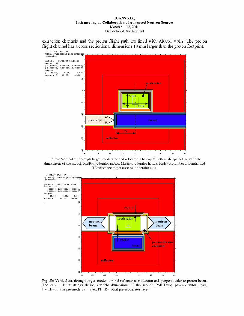
extraction channels and the proton flight path are lined with A16061 walls. The proton flight channel has a cross sectionional dimensions 10 mm larger than the proton footprint.
01/22/07 10i22i56
ICANS XIX,19th meeting on Collaboration of Advanced Neutron Sources
March 8 - 12, 2010Grindelwald, Switzerland
cylpHi cylindrical para nydrogan_
proud - 01/22/07 101211 It( O.OOOOOO, 0.000000, 1.00000 Oj,( 1.000000, 0.000000, 0.00000or
pbeampKH target
'MBH.
reflector
TO
iderator
-40 -30 -20 -10 0 10 20 30 40
Fig. 2a: Vertical cut through target, moderator and reflector. The capital letters strings define variable dimensions of the model: MBR=moderator radius, MBH=moderator height, PBH=proton beam height, and
TO=distance target nose to moderator axis.
01/22/07 10i23i25cylphi cylindrical para hydrogen. mndArAfnr 1
probid - 01/22/07 10i21i44
( 0.000000, 1.000000, O.OOOOOQj, ( 1.000000, 0.000000, O.OOOOOOT
PMLT
moderatorneutronbeam
neutron beam .
PMLB
target
reflector
Fig. 2b: Vertical cut through target, moderator and reflector at moderator axis perpendicular to proton beam. The capital letter strings define variable dimensions of the model: PMLT=top pre-moderator layer, PMLB=bottom pre-moderator layer, PBLR=radial pre-moderator layer.

ICANS XIX,19th meeting on Collaboration of Advanced Neutron Sources
March 8 - 12, 2010Grindelwald, Switzerland
01/22/07 10i23i56cylpbi cylindrical para hydrogenmsderAtnr
probld - 01/22/07 10i21i44
( 0.000000, 1.000000, 0.000000^ ( 0.000000, 0.000000, l.OOOOOtfl*
Pre-moderatorextensionPMRL
moderatorcontainment PMESL
PMESD
pre-moderator
reflector
Fig. 2c: Horizontal cut through center of moderator and reflector. The strings with capital letters define variable dimensions of the model: PMRL=pre-moderator radial layer, PMESD=pre-moderator extension thickness and PMESL=pre-moderator extension length.
5. Results
5.1 Performance Comparison Slab-box, Flux-trap-box, Wing-box and Wing-cylindrical Moderators
Typical for all moderator configurations was the moderator height converging to 120 mm, which is equivalent to the height of the viewed area. The pre-moderator layers thicknesses range from 5 to 20 mm depending on location and configuration. The premoderator layers adjacent to the target are 13-15 mm thick, except for the flux-trap configuration, where the OPTIMIZER made the layer at the target side vanish. The premoderator layer thickness along the neutron extraction channels tend to be somewhat thinner compared to the moderator pre-moderator layers, the extension length range from 25-50 mm. Details about the configurations and the resulting optimized parameters are to be found in an ORNL report [13].
The wing box moderator was found to be superior in time averaged cold neutron brightness followed by the slab box moderator configuration, the wing cylindrical and flux-trap box configurations as shown in Table I. Especially the flux-trap moderator seems to perform not favorably in this metric.
Energy spectra for these configurations are shown in Fig 3 a. The wing box and slab box moderators exhibit very similar flux spectra. The wing-cylindrical moderator exhibits as much as 50% lower neutron brightness with regard to the top performers especially for energies above 5 meV. It is viewed from two sides and therefore missing important premoderator backing. Much of the lost ground is gained back in the cold energy range.
Gains of time-averaged brightness of up to 5.5 are achieved compared against the SNS
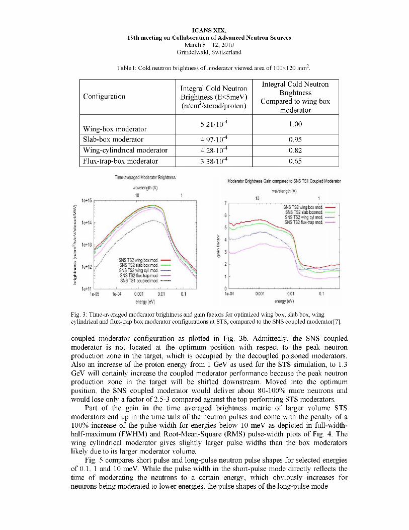
Table I: Cold neutron brightness of moderator viewed area of 100x120 mm2.
ICANS XIX,19th meeting on Collaboration of Advanced Neutron Sources
March 8 - 12, 2010Grindelwald, Switzerland
ConfigurationIntegral Cold Neutron Brightness (E<5meV) (n/cm2/sterad/proton)
Integral Cold Neutron Brightness
Compared to wing box moderator
Wing-box moderator 5.21-10-4 1.00
Slab-box moderator 4.97-10-4 0.95Wing-cylindrical moderator 4.28-10-4 0.82Flux-trap-box moderator 3.38-10-4 0.65
Time-averaged Moderator Brightness
SNS TS2 wing box mod ----- 'v*vSNSTS2 slab box mod.-----SNS TS2 wing cyl. mod.-----SNS TS2 flux-trap mod.-----SNS TS1 coupled mod - - - - - -
0.001energy (eV)
Moderator Brightness Gain compared to SNS TS1 Coupled Moderator
wavelength (A)
SNS TS2 wng box mod.SNS TS2 slab boxmodSNS TS2 wing cyl mod.-----SNS TS2 flux-trap mod.-----
Fig. 3: Time-averaged moderator brightness and gain factors for optimized wing box, slab box, wing cylindrical and flux-trap box moderator configurations at STS, compared to the SNS coupled moderator[7].
coupled moderator configuration as plotted in Fig. 3b. Admittedly, the SNS coupled moderator is not located at the optimum position with respect to the peak neutron production zone in the target, which is occupied by the decoupled poisoned moderators. Also an increase of the proton energy from 1 GeV as used for the STS simulation, to 1.3 GeV will certainly increase the coupled moderator performance because the peak neutron production zone in the target will be shifted downstream. Moved into the optimum position, the SNS coupled moderator would deliver about 80-100% more neutrons and would lose only a factor of 2.5-3 compared against the top performing STS moderators.
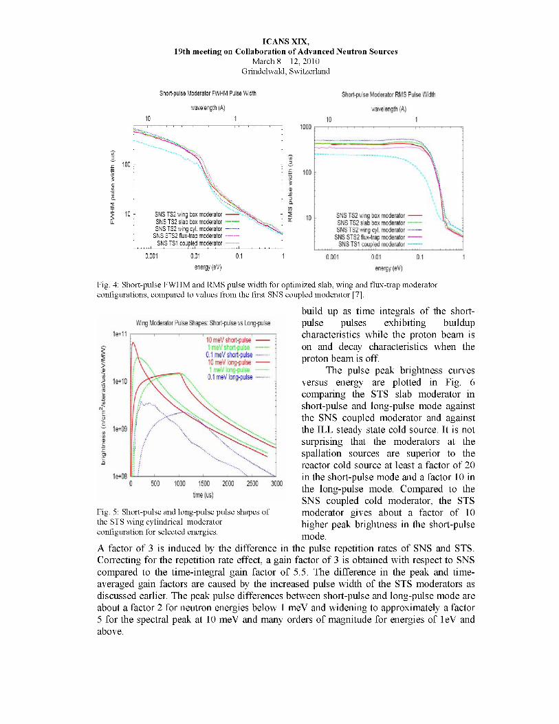
Part of the gain in the time averaged brightness metric of larger volume STS moderators end up in the time tails of the neutron pulses and come with the penalty of a 100% increase of the pulse width for energies below 10 meV as depicted in full-width- half-maximum (FWHM) and Root-Mean-Square (RMS) pulse-width plots of Fig. 4. The wing cylindrical moderator gives slightly larger pulse widths than the box moderators likely due to its larger moderator volume.
Fig. 5 compares short pulse and long-pulse neutron pulse shapes for selected energies of 0.1, 1 and 10 meV. While the pulse width in the short-pulse mode directly reflects the time of moderating the neutrons to a certain energy, which obviously increases for neutrons being moderated to lower energies, the pulse shapes of the long-pulse mode
ICANS XIX,19th meeting on Collaboration of Advanced Neutron Sources
March 8 - 12, 2010Grindelwald, Switzerland
Short-pulse Moderator FWHM Pulse Width
wavelength (A)
Short-pulse Moderator RMS Pulse Width
wavelength (A)
SNS TS2 wing box moderator- - - - - - x*SNS TS2 slab box moderator —SNS TS2 wing cyl. moderator. . . . . . .
SNS STS2 flux-trap moderator- - - - - -SNS TS1 coupled moderator
SNS TS2 wing box moderator-----SNS TS2 slab box moderator---- -SNS TS2 wing cyl. moderator-----
SNS STS2 flux-trap moderator-----SNS TS1 coupled moderator
energy (eV) energy (eV)
Fig. 4: Short-pulse FWHM and RMS pulse width for optimized slab, wing and flux-trap moderator configurations, compared to values from the first SNS coupled moderator [7].
build up as time integrals of the short- pulse pulses exhibiting buildupcharacteristics while the proton beam is on and decay characteristics when theproton beam is off.
The pulse peak brightness curves versus energy are plotted in Fig. 6 comparing the STS slab moderator in short-pulse and long-pulse mode against the SNS coupled moderator and against the ILL steady state cold source. It is not surprising that the moderators at the spallation sources are superior to the reactor cold source at least a factor of 20 in the short-pulse mode and a factor 10 in the long-pulse mode. Compared to the SNS coupled cold moderator, the STS moderator gives about a factor of 10 higher peak brightness in the short-pulse mode.
A factor of 3 is induced by the difference in the pulse repetition rates of SNS and STS. Correcting for the repetition rate effect, a gain factor of 3 is obtained with respect to SNS compared to the time-integral gain factor of 5.5. The difference in the peak and time- averaged gain factors are caused by the increased pulse width of the STS moderators as discussed earlier. The peak pulse differences between short-pulse and long-pulse mode are about a factor 2 for neutron energies below 1 meV and widening to approximately a factor 5 for the spectral peak at 10 meV and many orders of magnitude for energies of 1eV and above.
Fig. 5: Short-pulse and long-pulse pulse shapes of the STS wing cylindrical moderator configuration for selected energies.

ICANS XIX,19th meeting on Collaboration of Advanced Neutron Sources
March 8 - 12, 2010Grindelwald, Switzerland
Fig. 6: Peak moderator brightness for the STS slab configuration in short-pulse and long-pulse (1ms) mode compared against the SNS coupled moderator (short-pulse)[7], and against measured values of the ILL horizontal cold source operated at 60 MW reactor power[16].
Cold Flux (E<5meV) 10 meters versus Beamline Angle
slab moderator.-----cylindical wing moderator
Fig. 7: Neutron flux in a beam line viewing the moderator viewed area from an angle with regard to nominal beam direction for slab box and wing cylindrical moderators.
5.2 Off-normal-angle view of moderator
A moderator unit is supposed to serve multiple beamlines. For this reason, the neutron extraction channel widens up in the horizontal to allow an off-normal angle view of the moderator of up to ±30 degrees in the horizontal in the presented simulations. Calculations were performed to investigate the neutron flux intensity dependent on the viewing angle for the wing cylindrical moderator and the slab box moderator. The results are shown in Fig. 7. While for the cylindrical moderator the neutron flux intensity stays fairly flat for extraction angles ranging from 0 to 30 degrees, it degrades about 20% for the box moderators. We conclude that cylindrical moderators balance their lower on-normal performance by their higher off-normal performance.
5.3 Brightness profiles of neutron emission area
A pinhole tally was applied to obtain brightness profiles of the moderator neutron emission surface for selected configurations and for broad cold and thermal neutron energy groups. Profiles of wing cylindrical configurations are shown in Figs. 8. All profiles exhibit U- shaped curves indicating that the emission near pre-moderator volumes is favored.

ICANS XIX,19th meeting on Collaboration of Advanced Neutron Sources
March 8 - 12, 2010Grindelwald, Switzerland
Brightness Distribution Vertical:ver5mesm 1.0 MW 1.3 GeV
E=[,1.000001:-10] x500 —E=[1 .OOOOOE-10,1 .OOOOOE-09] x10.. . . .
E=[1 .OOOOOE-O9,1 .OOOOOE-081 xl . . . . . . .E=[1 .OOOOOE-O8,1 .OOOOOE-07] xl . . . . .
height (cm)
Brightness Distribution Horizontal verSmesm 1.0 MW 1.3 GeV
—• E«if 1: OOOOOE'- 0 8,1 .OOOOOE-07] x 1
width (cm)
Fig 8: Vertical and horizontal brightness distribution across the viewed moderator area of the STS wing- cylindrical moderator for four broad energy bands. The height and width coordinate describes the location
with respect to the moderator origin.
For the cylindrical moderator the horizontal profiles are fairly flat because the premoderators at the moderator sides are not in immediate vicinity of the extraction areas. Box moderators exhibit U-shaped profiles both in the vertical and horizontal and for this reason have better averaged cold neutron performance. Overall the profiles explain why the OPTIMIZER steered the moderator height to be exactly the height of the viewed moderator area, namely to enable the detector to view the brightness peaks at the premoderator moderator interface areas. For the slab box moderator, the profiles are symmetric in horizontal and vertical direction, while for the wing cylindrical moderator the vertical profile is skewed with higher neutron emission at the target near region.
5.7 Neutron Extraction Schemes at Cylindrical ModeratorsDifferent neutron extraction schemes as depicted in Fig. 9 were evaluated for the
cylindrical moderator configuration, which aimed at improving the overall cold neutron brightness and at improving the flux spectrum in the range 5-20 meV. In this energy range, we experienced a depression of neutron emission compared against the box moderator configurations, which we attributed to missing pre-moderator at the backside of the viewed moderator port. By introducing an off-axis, or a three-channel extraction scheme, we hoped to gain some of these neutrons back. While the off-axis scheme has the same channel width of 60 degrees as the nominal cylindrical moderator configuration, the channel widths of the three-face configuration was reduced to 36 degrees for the channel covering one side with respect to the proton beam axis, and to 24 degrees at the side covered by two channels. For a four-face scheme, channel widths of 24 degrees and 12 degrees were investigated.
All alternative options achieve higher cold neutron brightness values as listed in Table II. The gains range from 2-11% with the three-face scheme being the most promising. As hoped, the off-axis and three-face extraction schemes gain back gains in the energy range from 5-15 meV as much as 16%; these gains drop to 10% and 5% for energies below 5 meV for the three-face and off-axis schemes, respectively. For the three- face scheme, the channel with 36 degree shows 2% lower brightness than the narrower

ICANS XIX,19th meeting on Collaboration of Advanced Neutron Sources
March 8 - 12, 2010Grindelwald, Switzerland
(a) off-axis two-face (b) three-face (c) four-faceFig.9: Three alternative neutron extraction schemes.
Table II: Cold neutron brightness of moderator viewed area of 100x120 mm2 for wing cylindrical moderatorconfigurations
Configuration Integral Cold Neutron Brightness
Compared to wing cylindical moderator with two face extraction
Two face off-axis 1.07Three-face 1.11Four-face 24 degree channel 1.02
Four-face 12 degree channel 1.08
channel. For the four-face, the gain factor does not show a peaking in the 5-15 meV energy range but an overall gains of 3% and 8% below 15 meV for the 24 degree and 12 degree widened channels, respectively.
5.8 Moderator AlternativesA small list of alternative moderator materials are in use at pulsed neutron sources all
utilizing hydrogenious materials as solid and liquid methane, and solid mesitylene. All of these alternatives suffer either from storing chemical energy in the solid phase from radiation induced breakups of bonds, which needs to be released periodically by thermal annealing or replacement, or from deposition of carbon-hydrates and subsequent clogging up of piping. The thermalization characteristics of these alternative materials tend to favor small volume moderators, the brightness of which can be enhanced by adding groves at the emission faces.
Hence optimization studies were conducted with wing-box-type models that added parameterized groves. Two types of solid methane moderators were considered: the first one assumed methane in an aluminum sponge to extract the deposited heat, which was modeled by homogenizing 10 vol% aluminum to solid methane; the second type assumed pelletized solid methane submerged and cooled by a flow of liquid para-hydrogen modeled by a homogenious mixture of 60vol% solid methane and 40vol% para-hydrogen.
All the moderator alternative configurations optimized to a bulk moderator layer of 2.5 to 3 cm and grove depths of 3 to 5 cm with pre-moderator thicknesses of 1.2 - 2 cm. Fig. 10 compares time-averaged flux and peak spectra as well as full-width-at-half

maximum (FWHM) pulse widths of the moderator alternatives against the wing-box para- hydrogen moderator results.
For the time-averaged brightness, solid methane performs very similarly compared to para-hydrogen; solid mesetylene and liquid methane are inferior. All moderator alternatives achieve the moderation in a shorter time than para-hydrogen resulting in a shorter FWHM pulse width and for solid methane moderators in higher short-pulse peak brightness. In the long-pulse mode, the peak pulse brightness is merely a scaled image of the time-averaged brightness curves.
6. Conclusions
Optimization calculations were performed to assess the target/moderator/reflector assembly options for a second SNS target station with a focus on long-wavelength high- intensity neutron output. This study focused on a conservative concept using supercritical para-hydrogen moderators in wing, slab and flux-trap position on liquid mercury targets, surrounded by beryllium reflectors.
Although not the top performer in terms of cold neutron brightness, large cylindrical liquid para-hydrogen moderators with 12 cm height and 11 cm radius positioned in wing configuration at a flat mercury target surrounded by a pre-moderator layer of ambient water seem to be the preferred TMRA configuration. It has the big advantage over box moderators that one cylindrical moderator can feed 10-12 neutron beamlines through three viewing ports compared to 6 a box moderator could serve. On a cylindrical moderator practically all of the beamlines are uniformly illuminated, while on a box moderator the off-normal beamlines suffer severely.
Cold moderator alternatives in use at existing pulsed neutron sources such as solid and liquid methane, and solid mesitylene (all small volume box-type) did not show gains compared the para-hydrogen moderator for soures operated in long-pulse mode. In short- pulse mode, however, the solid methane moderator provides 50% higher peak brightness values compared to the para-hydrogen moderator. Considering the operations complexity that solid methane moderators exhibit at existing facilities (frequent need of annealing and hydro-carbon deposition), it is uncertain that they are a real alternative at mega-watt scale facilities.
7. References
1. National Spallation Neutron Source Conceptual Design Report, Oak Ridge National Laboratory, NSNS/CDR-2/VI, 1997.
2. The SNS Second Target Station Working GroupConceptual Design Study for a Second Target Station for the Spallatin Neutron Source, SNS 100000000-TR0029- R00, Oak Ridge National Laboratory, Oak Ridge, September 2008.
3. F. X. Gallmeier et al, Neutronics analyses in support of rotating target debvelopments at SNS, ICANS-XIX, at this conference.
4. B. Riemer et al, Results from Cavitation Damage Experiments with Mercury Spallation Targets at the LANSCE - WNR in 2008, ICANS-XIX, at this conference.
5. E. B. Iverson and J. M. Carpernter, Kinetics of Irradiated Liquid Hydrogen, In Proceedings of the 16th Meeting of the International Collaboration on Advanced Neutron Sources (ICANS-XVI), Dusseldorf-Neuss/Germany, May 12-15, 2003, editors: G. Mank and H. Conrad, Forschungszentrum Julich, ISSN 1433-559X (July 2003).
ICANS XIX,19th meeting on Collaboration of Advanced Neutron Sources
March 8 - 12, 2010Grindelwald, Switzerland

6. Iverson E.B. et al, Detailed SNS Neutronics Calculations for Scattering Instrument Design: SCT Configuration, SNS-1100403300-DA0001-R00, Oak Ridge National Laboratory, Oak Ridge, July 2002.
7. Pelowitz D. B., editor, MCNPX User’s Manual Version 2.5.0, LA-CP-05-0369, Los Alamos National Laboratory, Los Alamos, April 2005 (also see http://mcnpx.lanl.gov).
8. J. Mockus et al, Bayesian Heuristic Approach to discrete and Global Optimization, Kluwer Academic Publishers, Boston/London/Dordrecht, July 1996.
9. F. B. Brown, J. E. Sweezy, R. B. Hayes, Monte Carlo Parameter Studies and Uncertainty Analyses with MCNP5, LA-UR-04-0499, Los Alamos National Laboratory, Los Alamos, April 2004.
10. Carpenter J. M. et al., Technical concepts for a long-wavelength target station for the Spallation Neutron Source, ANL-02/16, Argonne National Laboratory, November 2002.
11. Russell G. J. et al, The LANCSE Target System, In Proceedings of the 9th Meeting of the International Collaboration on Advanced Neutron Sources (ICANS IX), Villigen/Switzerland, September 22-26, 1986, editors: F. Atchison and W. Fischer, Schweizer Institut fuer Nuclearforschung (SIN), ISBN 3-907998-01-4, July 1987, SIN Villigen.
12. Kai T. et al., Neutronic performance of rectangular and cylindrical coupled hydrogen moderators in wide-angle beam extraction of low-energy neutrons, NIM A 550 (2005), pp. 329-342.
13. F. X. Gallmeier and E. B. Iverson, Target Moderator Reflector Assemblies for the SNS Second Target Station, STS03-31-TR0001-R00, Oak Ridge National Laboratory, September 2008.
ICANS XIX,19th meeting on Collaboration of Advanced Neutron Sources
March 8 - 12, 2010Grindelwald, Switzerland

ICANS XIX,19th meeting on Collaboration of Advanced Neutron Sources
March 8 - 12, 2010Grindelwald, Switzerland
Fig. 10: Time-averaged moderator brightness, FWHM pulse-width, short-pulse and long-pulse peak brightness spectra for optimized STS TMRAs with alternate moderator materials: solid methane in 10vol% aluminum matrix, solid methane pellets in 40 vol% para-hydrogen, solid mesitylene in10vol% aluminum matrix, and liquid methane compared against a para-hydrogen TMRA.