socket heat fusion techniques - cb supplies ltd. heat fusion techniques a guide for instruction and...
TRANSCRIPT

Socket Heat Fusion Techniques
A Guide forInstruction and Training
in VanguardSocket Heat Fusion
vanguard pipe & fittings ltd. 1 Socket Heat FuSion GuiDe
TA B LE O F CO NTE NTS
This brochure has been developed to assist those responsible for socket fusion joining Vanguard Piping with PE 4710 Fittings.
SOCKET FUSION PROCEDURES 2 - 7
COOLING AND CURING CHART 5
BUTT WELDING 8 - 11 REVIEW AND REFERENCE 12
FUSION EXAMPLES 13
The procedures detailed herin are applicable to all PE4710 pipemanufactured according to ASTM D 3035 and D 2447 specifications.
vanguard pipe & fittings ltd.2 Socket Heat FuSion GuiDe
SO C KE T FU S I O N P ROC E D U R E S
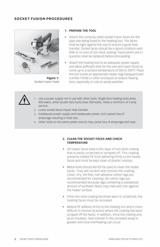
Figure 1: Socket Fusion Tools
1. Use a power supply not in use with other tools. Single face heating tools draw 400 watts, while double face tools draw 500 watts. Allow a minimum of 5 amp service.
2. Loose socket faces impair heat transfer.3. Inadequate power supply and inadequate power cord causes loss of
amperage resulting in heat loss.4. Other tools on the same power source may cause loss of amperage and heat.
1. PREPARE THE TOOL
• Attach the correctly sized socket fusion faces for the pipe size being fused to the heating tool. The faces shall be tight against the tool to ensure a good heat transfer. Socket faces should be in good condition with little or no loss of non-stick coating. Faces which are in question shall be replaced before proceeding.
• Attach the heating tool to an adequate power supply and allow sufficient time for the tool and fusion faces to come up to a surface temperature of 500 to 525°F. Place the tool inside an appropriate heater bag (Vanguard part number FHHB) or other enclosure to reduce heating time, especially in cold or windy weather.
2. CLEAN THE SOCKET FACES AND CHECK TEMPERATURE
• All heater faces have a thin layer of non-stick coating that is easily scratched or scraped off. This coating prevents melted PE from adhering firmly to the heater faces and must be kept clean of plastic residue.
• Metal tools should NEVER be used to clean the heater faces. They will scratch and remove the coating. Clean, dry, lint-free, non-abrasive cotton rags are recommended for cleaning. All-cotton rags are recommended because rags containing a substantial amount of synthetic fibers may melt and char against the heater surface.
• If the non-stick coating becomes worn or scratched, the heating faces must be recoated.
• Melted PE adheres firmly to the heating iron and is more difficult to remove at places where the coating has been scraped off the faces. In addition, since the coating acts as an insulator, heat transfer in the uncoated areas is greater and local overheating can occur.
vanguard pipe & fittings ltd. 3 Socket Heat FuSion GuiDe
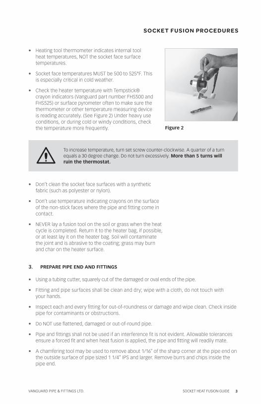
• Heating tool thermometer indicates internal tool heat temperatures, NOT the socket face surface temperatures.
• Socket face temperatures MUST be 500 to 525°F. This is especially critical in cold weather.
• Check the heater temperature with Tempstick® crayon indicators (Vanguard part number FHS500 and FHS525) or surface pyrometer often to make sure the thermometer or other temperature measuring device is reading accurately. (See Figure 2) Under heavy use conditions, or during cold or windy conditions, check the temperature more frequently. Figure 2
SOC KE T FU S I O N P ROC E D U R E S
• Don’t clean the socket face surfaces with a synthetic fabric (such as polyester or nylon).
• Don’t use temperature indicating crayons on the surface of the non-stick faces where the pipe and fitting come in contact.
• NEVER lay a fusion tool on the soil or grass when the heat cycle is completed. Return it to the heater bag, if possible, or at least lay it on the heater bag. Soil will contaminate the joint and is abrasive to the coating; grass may burn and char on the heater surface.
To increase temperature, turn set screw counter-clockwise. A quarter of a turn equals a 30 degree change. Do not turn excessively. More than 5 turns will ruin the thermostat.
3. PREPARE PIPE END AND FITTINGS
• Using a tubing cutter, squarely cut of the damaged or oval ends of the pipe.
• Fitting and pipe surfaces shall be clean and dry; wipe with a cloth, do not touch with your hands.
• Inspect each and every fitting for out-of-roundness or damage and wipe clean. Check inside pipe for contaminants or obstructions.
• Do NOT use flattened, damaged or out-of-round pipe.
• Pipe and fittings shall not be used if an interference fit is not evident. Allowable tolerances ensure a forced fit and when heat fusion is applied, the pipe and fitting will readily mate.
• A chamfering tool may be used to remove about 1/16” of the sharp corner at the pipe end on the outside surface of pipe sized 1 1/4” IPS and larger. Remove burrs and chips inside the pipe end.
vanguard pipe & fittings ltd.4 Socket Heat FuSion GuiDe
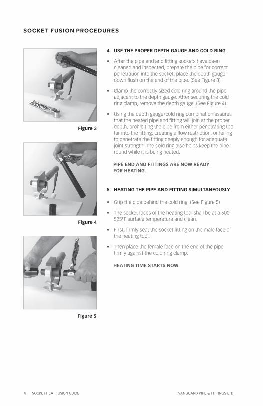
Figure 3
Figure 4
Figure 5
4. USE THE PROPER DEPTH GAUGE AND COLD RING
• After the pipe end and fitting sockets have been cleaned and inspected, prepare the pipe for correct penetration into the socket, place the depth gauge down flush on the end of the pipe. (See Figure 3)
• Clamp the correctly sized cold ring around the pipe, adjacent to the depth gauge. After securing the cold ring clamp, remove the depth gauge. (See Figure 4)
• Using the depth gauge/cold ring combination assures that the heated pipe and fitting will join at the proper depth, prohibiting the pipe from either penetrating too far into the fitting, creating a flow restriction, or failing to penetrate the fitting deeply enough for adequate joint strength. The cold ring also helps keep the pipe round while it is being heated.
PIPE END AND FITTINGS ARE NOW READY FOR HEATING.
5. HEATING THE PIPE AND FITTING SIMULTANEOUSLY
• Grip the pipe behind the cold ring. (See Figure 5)
• The socket faces of the heating tool shall be at a 500-525°F surface temperature and clean.
• First, firmly seat the socket fitting on the male face of the heating tool.
• Then place the female face on the end of the pipe firmly against the cold ring clamp.
HEATING TIME STARTS NOW.
SO C KE T FU S I O N P ROC E D U R E S
vanguard pipe & fittings ltd. 5 Socket Heat FuSion GuiDe
Figure 6
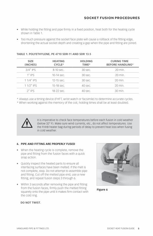
It is imperative to check face temperatures before each fusion in cold weather (below 32° F). Make sure wind currents, etc., do not affect temperatures. Use the FHHB heater bag during periods of delay to prevent heat loss when fusing in cold weather.
• While holding the fitting and pipe firmly in a fixed position, heat both for the heating cycle shown in Table 1.
• Too much pressure against the socket face plate will cause a rollback of the fitting edge, shortening the actual socket depth and creating a gap when the pipe and fitting are joined.
TABLE 1. POLYETHYLENE, PE 4710 SDR-11 AND SDR 13.5
SOC KE T FU S I O N P ROC E D U R E S
SIZE(INCHES)
HEATING CYCLE*
HOLDING TIME*
CURING TIME BEFORE HANDLING*
3/4” IPS 8-10 sec. 30 sec. 20 min.
1” IPS 10-14 sec. 30 sec. 20 min.
1 1/4” IPS 12-15 sec. 30 sec. 20 min.
1 1/2” IPS 15-18 sec. 40 sec. 20 min.
2” IPS 18-22 sec. 40 sec. 30 min.
* Always use a timing device (FHFT, wrist watch or facsimile) to determine accurate cycles.* When working against the memory of the coil, holding times shall be at least doubled.
6. PIPE AND FITTING ARE PROPERLY FUSED
• When the heating cycle is complete, remove the pipe and fitting from the fusion faces with a quick snap action.
• Quickly inspect the heated parts to ensure all interfacing surfaces have been melted. If the melt is not complete, stop. Do not attempt to assemble pipe and fitting. Cut off the melted pipe end, use a new fitting, and repeat fusion steps 3 through 6.
• Within 3 seconds after removing the pipe and fitting from the fusion faces, firmly push the melted fitting squarely onto the pipe until it makes firm contact with the cold ring.
DO NOT TWIST.
vanguard pipe & fittings ltd.6 Socket Heat FuSion GuiDe
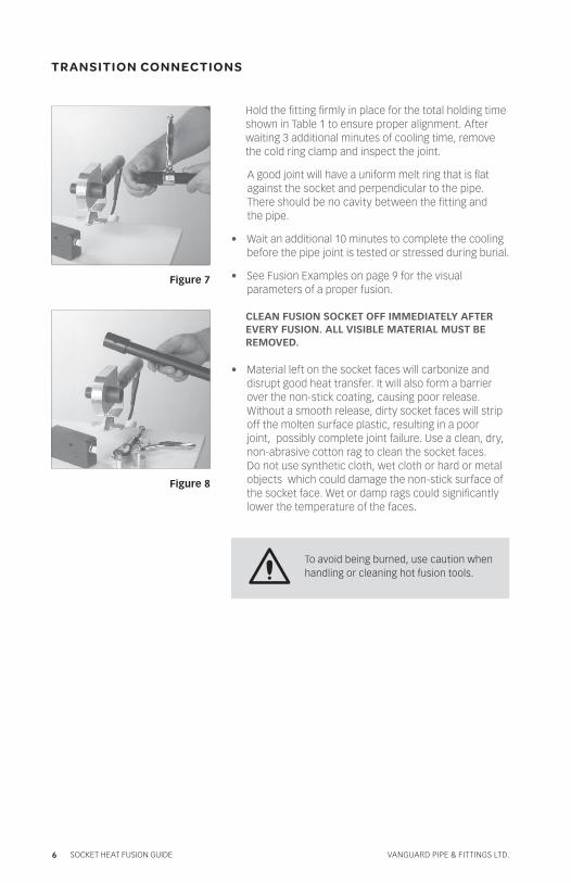
To avoid being burned, use caution when handling or cleaning hot fusion tools.
Figure 7
Figure 8
T R A N S ITI O N CO N N EC TI O N S
Hold the fitting firmly in place for the total holding time shown in Table 1 to ensure proper alignment. After waiting 3 additional minutes of cooling time, remove the cold ring clamp and inspect the joint.
A good joint will have a uniform melt ring that is flat against the socket and perpendicular to the pipe. There should be no cavity between the fitting and the pipe.
• Wait an additional 10 minutes to complete the cooling before the pipe joint is tested or stressed during burial.
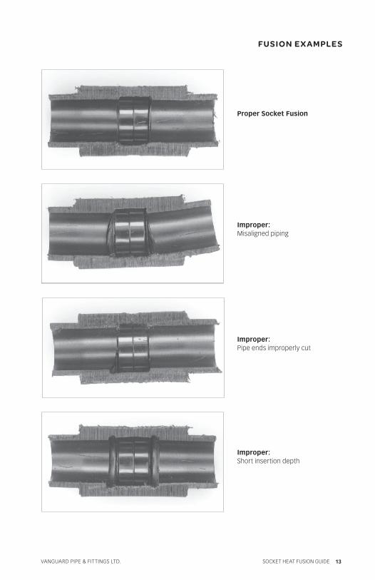
• See Fusion Examples on page 9 for the visual parameters of a proper fusion.
CLEAN FUSION SOCKET OFF IMMEDIATELY AFTER EVERY FUSION. ALL VISIBLE MATERIAL MUST BE REMOVED.
• Material left on the socket faces will carbonize and disrupt good heat transfer. It will also form a barrier over the non-stick coating, causing poor release. Without a smooth release, dirty socket faces will strip off the molten surface plastic, resulting in a poor joint, possibly complete joint failure. Use a clean, dry, non-abrasive cotton rag to clean the socket faces. Do not use synthetic cloth, wet cloth or hard or metal objects which could damage the non-stick surface of the socket face. Wet or damp rags could significantly lower the temperature of the faces.
vanguard pipe & fittings ltd. 7 Socket Heat FuSion GuiDe
If a leak is detected, joint shall beremoved and replaced. Do not attemptto “putty” leaks at a fusion joint.
P RO P E R U S E O F M ATE R IA L S
TESTING FOR LEAKS
Upon completion of the installation, the system should be hydrostatically tested. Hydrostatic testing of the system is to be conducted according to local code requirements. Test pressure shall be at least expected working pressure of the system, but not less than 40 psi nor greater than the maximum working pressure of the pipe or the maximum test pressure recommended by the manufacturer.
The following is an option method which applies to test pressures up to 225 psi:
• During the initial pressurization period, the pressure indicated on the gauge will decrease due to the initial deformation of the tubing, followed by a slow expansion. The amount of pressure drop will depend on ambient temperature, system capacity and test pressure. If additional makeup water is introduced into the system to achieve the original test pressure after the first 1 1/2 hours of the test, the pressure decrease during the next 2 hours should be less than the loss in the first 1 1/2 hours.
• The pressure decrease due to pipe deformation and expansion shall not exceed 10 percent during the initial 2 hours of the test period, after which the expansion shall not cause the pressure to decrease more than 3 percent during the next 2 hour period.
vanguard pipe & fittings ltd.8 Socket Heat FuSion GuiDe
B u t t We ld i n g
A. PrinciPle
Butt welding involves the heating of two pipe ends to fusion temperature and then subsequently joining the two ends by the application of force.
B. QuAlity Butt Welds
The most usual cause of poor quality butt welds is the inattention of the butt welder to the proper timing, temperature, and pressure.
A successful weld is simply described as having a joint equal or exceeding the strength of the pipe itself. thus, a hydrostatic pressure test of the pipe with the joint must lead to a failure in the pipe section – not in the joint section.
Vanguard Piping Systems has a complete set of hydrostatic burst test equipment. The people in the R&D department are capable of making quality butt welds and illustrating this with a burst test.
c. eQuiPment
The basic parts of the equipment are the following:
1. Planning Tool – used to face pipe ends
2. Heating Plate – used to melt pipe ends
3. Frame – holds on to the pipes to be joined. Some have spring tension where others are hydraulic cylinders which apply pressure to the pipe joints
4. Hydraulic unit (some units)– have the hydraulic pump, tank, pressure gauges, directional valves, pressure regulation valves
5. Data Logger (some units) – records pertinent process data such as time, pressure and temperature. The data logger ensures that every joint is made properly
vanguard pipe & fittings ltd. 9 Socket Heat FuSion GuiDe
B u t t We ld i n g
D. Site PreParation
Before butt welding, the operator must ensure that the machine is situated in a dry area. The equipment may not be exposed to rain.
If the butt welding has to be done outside appropriate measures must be taken when butt welding during in rainy weather. An outdoor roofing structure must be employed to protect the equipment from rain. The operator must also ensure that the equipment does not sit on wet ground.
e. PiPe PreParation
Pipe ends to be joined must be dry and free from foreign particles.Smaller butt welds can be done in the shop (a controlled environment).
Also it is not necessary to perform butt welding in trench. The installation of HDPE pipes has the convenient advantage over other piping materials of above ground jointing. That is, HDPE pipes can be butt weld on ground and subsequently pushing the pipes into the trench.
F. WelDing ProceDure
1. Securely fasten the pipes to be joined to the butt welding tool. The pipes must be attached square to the axial direction.
2. Face the pipe ends. The process is complete when the shavings are continuous in length and are equal in thickness. The faced ends must be moved to touch each other in order to ensure that both sides are square to each other. Remove any excess shavings using a tool. DO NOT TOUCH WITH HANDS / FINGERS. The grease from your fingers is enough to cause a void, or bad weld. The operator must not touch that faced ends at this point in order to prevent contamination.
3. For larger pipes the drag force must be accounted. Heating pressure and soak pressure have to be about 0.16 N/mm^2. On the site however, long lengths of pipes being connected one by one presents a varying levels of drag force. The user thus must be able to compensate the drag force so that the effective welding or soaking pressure are maintained at 0.16N/mm^2. It is important that this pressure is attained. V Volume reduction of plastic in its solidification from the melted state would lead to cavitations (air pockets) in the joint if the proper level of welding pressure is not reached.
vanguard pipe & fittings ltd.10 Socket Heat FuSion GuiDe
B u t t We ld i n g
4. For the smaller pipes the tool must be maintained at approximately 500F – 525F.
5. Melt the pipe interfaces. Follow the recommended heating times from the Table 1 in the Socket Welding Guide. Generally, a set level of bead height must be attained for a given pipe wall thickness. Bead height refers to the melted plastic that forms around the outer circumference of the pipe. Bead height may vary from 0.5mm to more than 5mm. The recommended heating up pressure is 0.16 N/mm^2 (effective). Again, effective means that drag forces must be compensated. A uniform bead is an indication of a good weld, but not confirmation. A pressure test must be performed.
6. Soak the pipe ends in heat. When the designated heating time is up, the high pressure is relieved but the pipes remain in contact with the heating plate. Heat soak time varies from 5 seconds to several minutes. Heat soak pressure is about 0.02 N/mm^2 effective.
vanguard pipe & fittings ltd. 11 Socket Heat FuSion GuiDe
B u t t We ld i n g
7. Changeover time. After the pipes have been properly soaked, the pipes must be immediately joined together. There is a changeover time – this refers to the maximum amount of time the pipes can be exposed to the atmosphere while removing the heating plate and moving the pipe ends together. Again, follow the recommended changeover time of the manufacturer of the butt welding equipment (3 seconds or less).
8. Welding (a.k.a. Cooling). After following the correct elapsed time for heating , soaking, and changeover, the pipe ends must be pressed together at an effective pressure of 0.15 N/mm^2. Cooling time under pressure varies from 6 minutes to 80 minutes. Failure to follow the correct cooling times may lead to the formation of air bubbles in the joint.
9. Wait an additional 10 minutes to complete the cooling before the pipe joint is tested or stressed during burial.
10. Always put the joint under a pressure test before burial.
vanguard pipe & fittings ltd.12 Socket Heat FuSion GuiDe
SOC KE T H E AT FU S I O N
REVIEW AND REFERENCE
1. Attach the correct socket faces, which are in good condition, to the heating body of the tool.
2. Connect tool to an adequate power supply (120 volts A.C.)
3. Heat faces between 500 and 525° F. Adjust temperature as necessary.
4. Square pipe ends with a pipe cutter designed for plastic pipe.
5. Wipe pipe end and fitting clean with a damp cloth.
6. Insert pipe end into the properly-sized depth gauge and attach the proper sized cold ring onto the pipe.
7. Begin timing the “HEAT CYCLE” as soon as the pipe and fitting are properly positioned on the pre-heated socket faces.
8. At the conclusion of the “HEATING CYCLE”, snap the pipe and fitting from the tool.
9. Within three seconds, push the pipe and fitting together squarely without twisting.
10. Hold firmly together for the specified “HOLDING TIME”.
11. Wipe hot socket faces clean with a clean, dry, non-abrasive cotton cloth.
12. Visually inspect each fusion joint.
vanguard pipe & fittings ltd. 13 Socket Heat FuSion GuiDe
FU S I O N E X A M PLE S
Proper Socket Fusion
Improper:Misaligned piping
Improper:Pipe ends improperly cut
Improper:Short insertion depth

Socket Heat Fusion Techniques
Vanguard Pipe & Fittings Ltd.8125 North Fraser WayBurnaby, BC V5J 5M8Canada
F. 604.431.5029T. 604.431.5024TF. 888.PIPEPEX (747.3739)
vanguard.ca
© 2011 VaNguard PIPE & FIttINgs ltd. PrINtEd IN CaNada. hsFg-1-2011