sodium as a fast reactor coolant - brave new · pdf file03.05.2007 · sodium as a...
TRANSCRIPT
Sodium as a Fast Reactor Coolant
Presented by
Thomas H. FanningNuclear Engineering Division
U.S. Department of EnergyU.S. Nuclear Regulatory CommissionTopical Seminar Series on Sodium Fast Reactors May 3, 2007
2
BackgroundUnless new sources of energy are found, the development of nuclear power will necessarily depend on fast reactors.– Fast reactors are not a new technology.– Fast reactors have achieved well over 300 reactor-years of operation.
To support effective actinide management (as envisioned by GNEP) a fast reactor must have a compact core with a minimum of materials which absorb or moderate fast neutrons. This places a significant heat transfer requirement on the coolant.
The choice of coolant determines the main design approaches and the technical and economic characteristics of a nuclear power plant.– Historically, this requirement has been met by the use of sodium in
nearly all fast reactors constructed and operated.– The Generation IV International Forum (GIF) identified three fast reactor
concepts for potential future development: SFR, LFR, and GFR.
3
ObjectivesIdentify important differences between sodium and other fast reactor coolants (lead/LBE and helium) and why sodium is preferred.Characterize the nature of sodium interactions with air and water.Understand how differences between sodium and water result in broad design differences between a sodium-cooled fast reactor (SFR) and a light-water reactor.
4
Topics to be CoveredHistorical Perspective on Reactor Coolants– Coolants that have been used in the past– Coolants for future fast reactors: sodium, lead, helium
Comparison of Sodium with other Fast Reactor Coolant Options– Thermophysical properties– Material properties– Neutronic properties– Safety– Cost– Other issues
Sodium Reactivity with Air and WaterImpact of Coolant on SFR and LWR Differences– Operating Pressure– Thermal Margins– Plant Design
Summary
5
Historical Perspective on Reactor Coolants
6
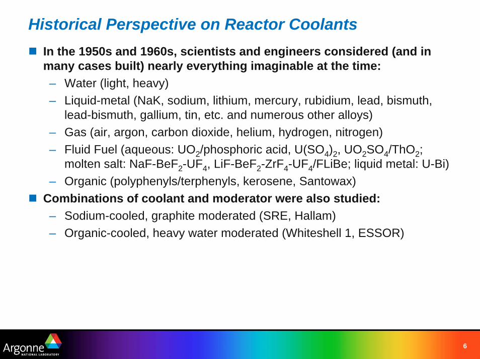
Historical Perspective on Reactor CoolantsIn the 1950s and 1960s, scientists and engineers considered (and in many cases built) nearly everything imaginable at the time:– Water (light, heavy)– Liquid-metal (NaK, sodium, lithium, mercury, rubidium, lead, bismuth,
lead-bismuth, gallium, tin, etc. and numerous other alloys)– Gas (air, argon, carbon dioxide, helium, hydrogen, nitrogen)– Fluid Fuel (aqueous: UO2/phosphoric acid, U(SO4)2, UO2SO4/ThO2;
molten salt: NaF-BeF2-UF4, LiF-BeF2-ZrF4-UF4/FLiBe; liquid metal: U-Bi)– Organic (polyphenyls/terphenyls, kerosene, Santowax)
Combinations of coolant and moderator were also studied:– Sodium-cooled, graphite moderated (SRE, Hallam)– Organic-cooled, heavy water moderated (Whiteshell 1, ESSOR)
7
Facility CountryFirst
Critical Coolant
Clementine USA 1946 Mercury
BR-2 Russia 1956 Mercury
SEFOR USA 1969 Sodium
KNK-II Germany 1972 Sodium
BN-350 Kazakhstan 1972 Sodium
Phenix France 1973 Sodium
FFTF USA 1980 Sodium
BN-600 Russia 1980 Sodium
FBTR India 1985 Sodium
Super-Phenix France 1985 Sodium
EBR-I USA 1951 NaK
BR-5/BR-10 Russia 1958 Sodium
DFR UK 1959 NaK
Fermi USA 1963 Sodium
EBR-II USA 1963 Sodium
Rapsodie France 1967 Sodium
BOR-60 Russia 1968 Sodium
PFR UK 1974 Sodium
JOYO Japan 1982 Sodium
MONJU Japan 1995 Sodium
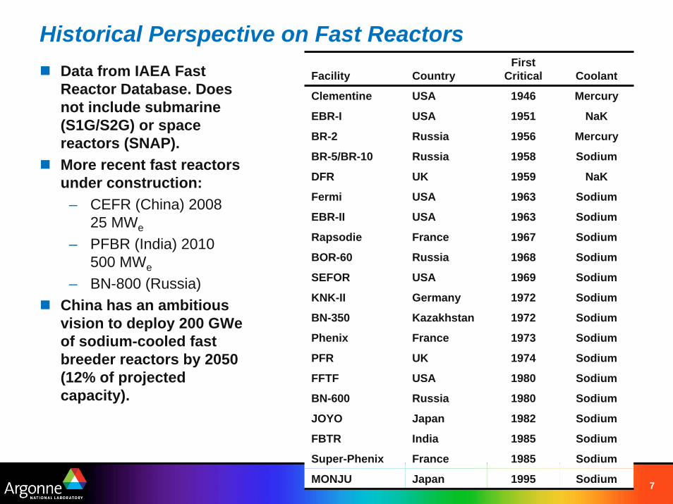
Historical Perspective on Fast ReactorsData from IAEA Fast Reactor Database. Does not include submarine (S1G/S2G) or space reactors (SNAP).More recent fast reactors under construction:
– CEFR (China) 200825 MWe
– PFBR (India) 2010500 MWe
– BN-800 (Russia)China has an ambitious vision to deploy 200 GWeof sodium-cooled fast breeder reactors by 2050 (12% of projected capacity).
8
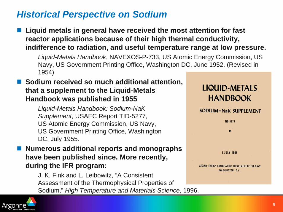
Historical Perspective on SodiumLiquid metals in general have received the most attention for fast reactor applications because of their high thermal conductivity,indifference to radiation, and useful temperature range at low pressure.
Liquid-Metals Handbook, NAVEXOS-P-733, US Atomic Energy Commission, US Navy, US Government Printing Office, Washington DC, June 1952. (Revised in 1954)
Sodium received so much additional attention, that a supplement to the Liquid-Metals Handbook was published in 1955
Liquid-Metals Handbook: Sodium-NaK Supplement, USAEC Report TID-5277, US Atomic Energy Commission, US Navy, US Government Printing Office, Washington DC, July 1955.
Numerous additional reports and monographs have been published since. More recently, during the IFR program:
J. K. Fink and L. Leibowitz, “A Consistent Assessment of the Thermophysical Properties of Sodium,” High Temperature and Materials Science, 1996.

9
Historical Perspective on LBEIn the U.S., use of lead/LBE was dismissed early mainly due to high pumping power requirements.A program for studying compatibility of lead, bismuth, and their alloys with structural materials existed at BNL between 1950 and 1962 as part of the Liquid Metal Fuel Reactor program.– Focus was on development/testing of a natural U-Bi liquid metal fuel.– An in-pile liquid-metal fuel loop was constructed and tested in the 1950s
Recent interest in lead and LBE developed as part of their application to accelerator-driven systems as target/coolant materials.The only LBE-cooled reactors are those developed for the Soviet Project 705 (Alfa-class) submarines– Modified November-class (Project 645) commissioned in 1963 to test
reactors intended for Alfa-class submarines.– Initial prototype (Project 661/Papa Class)
commissioned in 1969.– Production started in 1974, with first
commissioning in 1977. Production ended in 1983 with seven vessels.
10
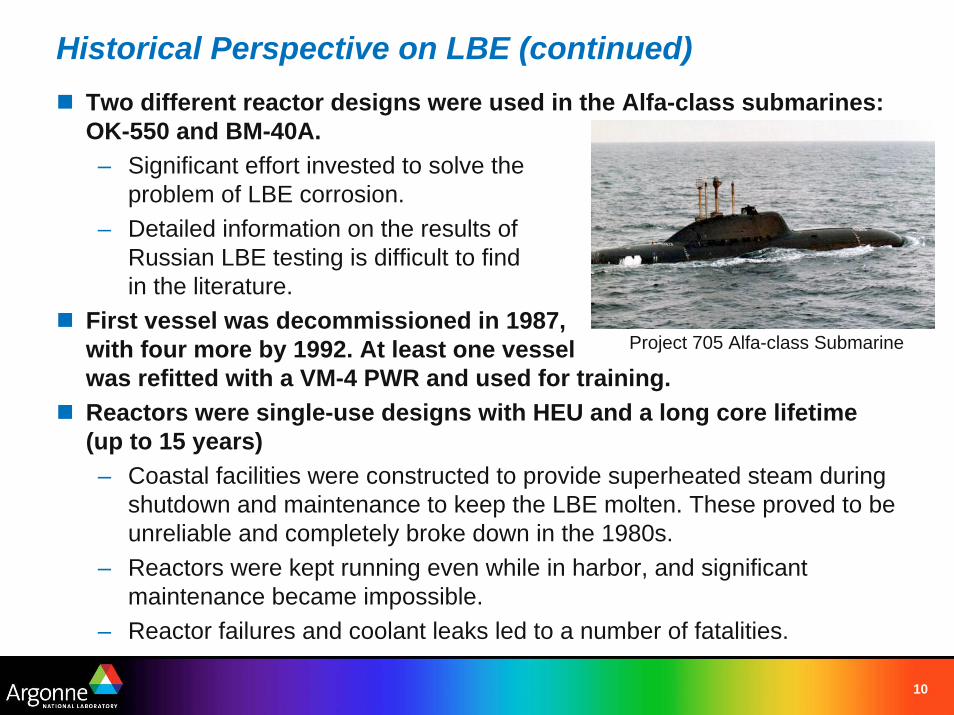
Historical Perspective on LBE (continued)Two different reactor designs were used in the Alfa-class submarines: OK-550 and BM-40A.– Significant effort invested to solve the
problem of LBE corrosion.– Detailed information on the results of
Russian LBE testing is difficult to find in the literature.
First vessel was decommissioned in 1987, with four more by 1992. At least one vessel was refitted with a VM-4 PWR and used for training.Reactors were single-use designs with HEU and a long core lifetime (up to 15 years)– Coastal facilities were constructed to provide superheated steam during
shutdown and maintenance to keep the LBE molten. These proved to be unreliable and completely broke down in the 1980s.
– Reactors were kept running even while in harbor, and significantmaintenance became impossible.
– Reactor failures and coolant leaks led to a number of fatalities.
Project 705 Alfa-class Submarine
11
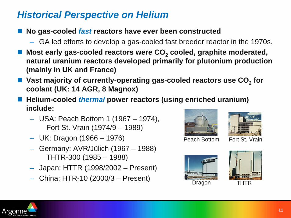
Historical Perspective on HeliumNo gas-cooled fast reactors have ever been constructed– GA led efforts to develop a gas-cooled fast breeder reactor in the 1970s.
Most early gas-cooled reactors were CO2 cooled, graphite moderated, natural uranium reactors developed primarily for plutonium production (mainly in UK and France)Vast majority of currently-operating gas-cooled reactors use CO2 for coolant (UK: 14 AGR, 8 Magnox)Helium-cooled thermal power reactors (using enriched uranium) include:– USA: Peach Bottom 1 (1967 – 1974),
Fort St. Vrain (1974/9 – 1989)– UK: Dragon (1966 – 1976)– Germany: AVR/Jülich (1967 – 1988)
THTR-300 (1985 – 1988)– Japan: HTTR (1998/2002 – Present)– China: HTR-10 (2000/3 – Present) Dragon THTR
Peach Bottom Fort St. Vrain
12
Properties of Fast Reactor Coolants: Sodium, Lead/LBE, and Helium
13
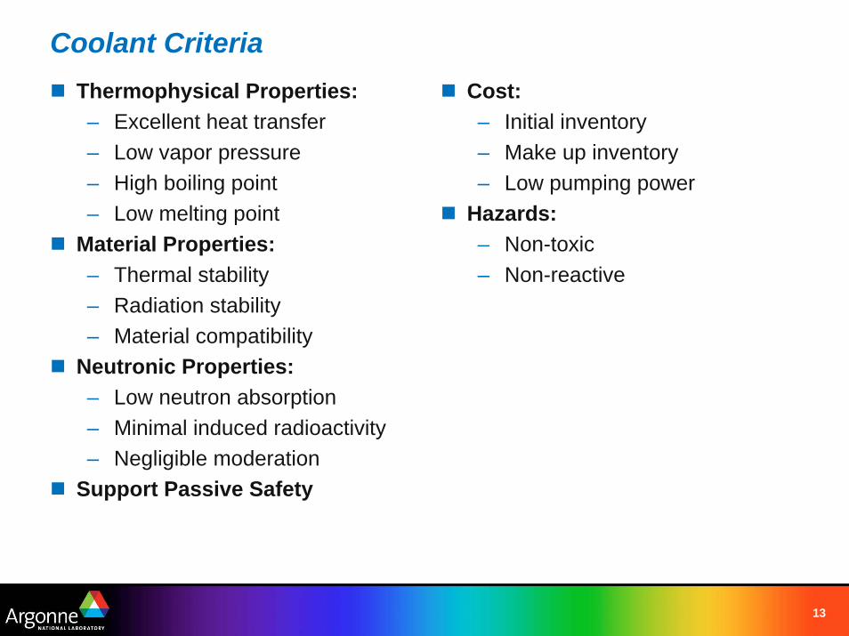
Coolant CriteriaThermophysical Properties:– Excellent heat transfer– Low vapor pressure– High boiling point– Low melting point
Material Properties:– Thermal stability– Radiation stability– Material compatibility
Neutronic Properties:– Low neutron absorption– Minimal induced radioactivity– Negligible moderation
Support Passive Safety
Cost:– Initial inventory– Make up inventory– Low pumping power
Hazards:– Non-toxic– Non-reactive
14
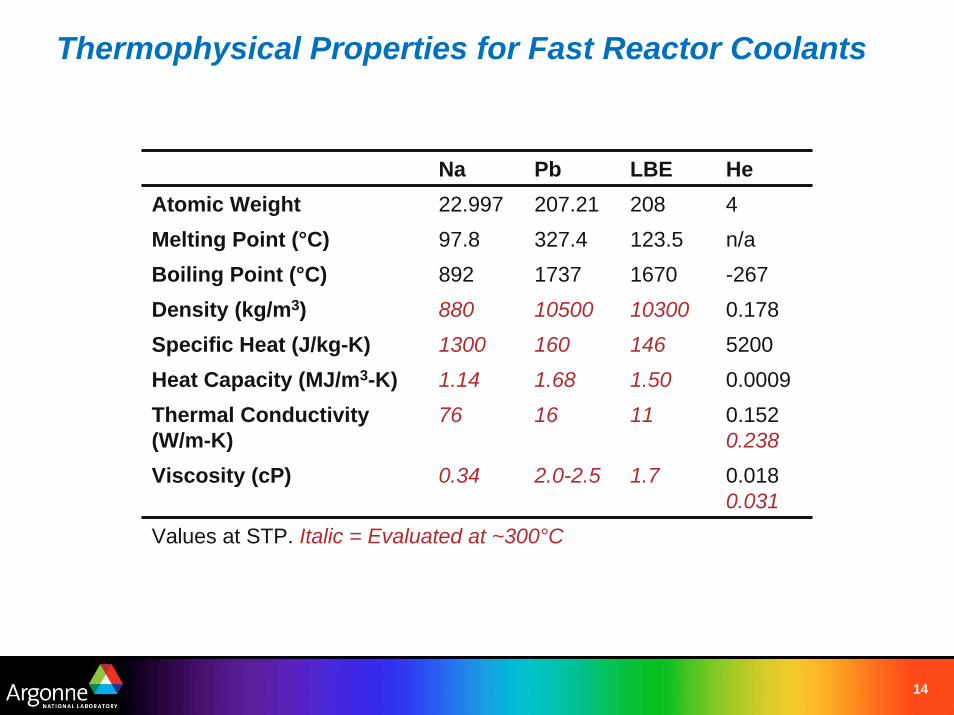
Thermophysical Properties for Fast Reactor Coolants
Na Pb LBE HeAtomic Weight 22.997 207.21 208 4Melting Point (°C) 97.8 327.4 123.5 n/a
Heat Capacity (MJ/m3-K) 1.14 1.68 1.50 0.0009Thermal Conductivity (W/m-K)
76 16 11 0.1520.238
Viscosity (cP) 0.34 2.0-2.5 1.7 0.0180.031
Boiling Point (°C) 892 1737 1670 -267Density (kg/m3) 880 10500 10300 0.178Specific Heat (J/kg-K) 1300 160 146 5200
Values at STP. Italic = Evaluated at ~300°C
15
Thermophysical PropertiesDespite very different densities and specific heat, sodium and LBE have similar volumetric heat capacities.– Similar volumetric flow rates– For identical flow geometries, similar flow velocity. But LBE will have a
significantly higher pressure drop and pumping requirements.– LBE will develop slightly higher natural circulation velocity, but at the
expense of somewhat higher cladding temperatures.Relatively low thermal conductivity of LBE (combined with low flow velocity) affects heat transfer from cladding to coolant.
Specific heat of helium is high, but density is very low. Requires a high pressure system (~85 atm) and high coolant velocity (~100 m/s). Introduces risk of flow-induced vibrations.Low thermal conductivity of helium results in poor heat transfer even at high coolant velocity. Cladding surfaces can be roughened to improve heat transfer (4x), but it is still 8-9x lower than for sodium.
16
Material PropertiesSodium, LBE, helium have excellent thermal and radiation stability.Compatibility of coolants with available structural, heat exchanger, and pump materials is a key criteria for selection.– Helium is chemically inert, but low molecular weight leads to diffusive
losses at seals and valves. Impurities (especially moisture) can lead to corrosion.
– Liquid metals may selectively deplete constituents from, and impurities may chemically react with, structural materials
– Chemistry control will be required for all coolants.Standards for sodium:– ASTM C 1051–85: “Standard Specification for Sodium as a Coolant For
Liquid Metal-Cooled Reactors” (withdrawn in 2000).– ASTM C 997–83: “Standard Test Methods for Chemical and
Instrumental Analysis of Nuclear-Grade Sodium and Cover Gas”(withdrawn in 1999).
17
Material Properties (Sodium)Primary issue with sodium is its chemical reactivity in air and water.Sodium is inherently compatible with stainless steels, requiring no special corrosion protection measures– Oxygen preferentially reacts with sodium, forming Na2O.– Oxygen impurity can readily be maintained well below 10 ppm using a
cold trap.– No difference between high-purity sodium and helium when comparing
strain-rate and creep-rupture data for austenitic steels. No indication of liquid metal embrittlement.
– Based on long-term corrosion testing in BR-10, “the operating service life of sodium equipment in fast reactors can be increased to 60 yr and longer.”
Fuel-coolant interactions are benign for metallic fuel.Many fission products are soluble in sodium and can be filtered out in the cold trap.Database for sodium compatibility is extensive, with informationavailable in the open literature.
18
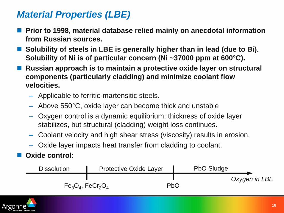
Material Properties (LBE)Prior to 1998, material database relied mainly on anecdotal information from Russian sources.Solubility of steels in LBE is generally higher than in lead (due to Bi). Solubility of Ni is of particular concern (Ni ~37000 ppm at 600°C).Russian approach is to maintain a protective oxide layer on structural components (particularly cladding) and minimize coolant flow velocities.– Applicable to ferritic-martensitic steels.– Above 550°C, oxide layer can become thick and unstable– Oxygen control is a dynamic equilibrium: thickness of oxide layer
stabilizes, but structural (cladding) weight loss continues.– Coolant velocity and high shear stress (viscosity) results in erosion.– Oxide layer impacts heat transfer from cladding to coolant.
Oxide control:
Dissolution Protective Oxide Layer PbO Sludge
Oxygen in LBEPbOFe3O4, FeCr2O4
19
Oxide Control in LBE SystemsOxygen is controlled by constant addition (e.g. flow over PbO “balls”) and subtraction (e.g. bubbling hydrogen gas in a helium carrier to form water).Problems with oxygen control:– Non-homogeneous oxygen distribution in real systems results in non-
uniform coatings. Crevice corrosion and dissolution of occlusions can occur.
– Magnetite (Fe3O4) undergoes a phase transformation at 570°C.Newer solution is to prefer SiO2 and Al2O3 based oxide layers.– Oxide layer forms at lower oxygen concentrations.– No phase transformation.– EP-823 (Russian steel similar to HT-9 but with higher Si content).– Silicon degrades mechanical properties (ductility) and reduces irradiation
performance.– Some interest in oxide dispersion strengthened (ODS) steels. Irradiation
performance and cost are not well known.
20
Neutronic CharacteristicsSodium, Lead, LBE, and Helium are all suitable for fast reactor applications– Sodium and LBE both introduce a small amount of parasitic absorption.– Reduced neutron leakage in an LBE system allows for a higher coolant
volume fraction.– Helium is transparent to neutrons, and the relatively low density leads to
negligible moderation, but this leads to a higher neutron leakage fraction.
21
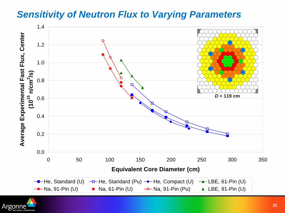
Sensitivity of Neutron Flux to Varying Parameters
0.0
0.2
0.4
0.6
0.8
1.0
1.2
1.4
0 50 100 150 200 250 300 350
Equivalent Core Diameter (cm)
Ave
rage
Exp
erim
enta
l Fas
t Flu
x, C
ente
r(1
015 n
/cm
2 /s)
He, Standard (U) He, Standard (Pu) He, Compact (U) LBE, 61-Pin (U)Na, 91-Pin (U) Na, 61-Pin (U) Na, 91-Pin (Pu) LBE, 91-Pin (U)
D = 119 cm
22
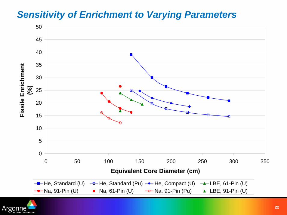
Sensitivity of Enrichment to Varying Parameters
0
5
10
15
20
25
30
35
40
45
50
0 50 100 150 200 250 300 350
Equivalent Core Diameter (cm)
Fiss
ile E
nric
hmen
t(%
)
He, Standard (U) He, Standard (Pu) He, Compact (U) LBE, 61-Pin (U)Na, 91-Pin (U) Na, 61-Pin (U) Na, 91-Pin (Pu) LBE, 91-Pin (U)
23
Scaling to Higher Power
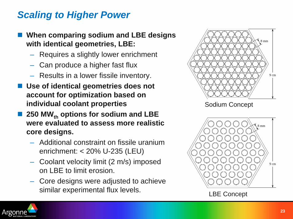
When comparing sodium and LBE designswith identical geometries, LBE:– Requires a slightly lower enrichment– Can produce a higher fast flux– Results in a lower fissile inventory.
Use of identical geometries does not account for optimization based on individual coolant properties250 MWth options for sodium and LBE were evaluated to assess more realistic core designs.– Additional constraint on fissile uranium
enrichment: < 20% U-235 (LEU)– Coolant velocity limit (2 m/s) imposed
on LBE to limit erosion.– Core designs were adjusted to achieve
similar experimental flux levels.
9 cm
8 mm
Sodium Concept
9 cm
8 mm
LBE Concept
24
Scaling to Higher Power
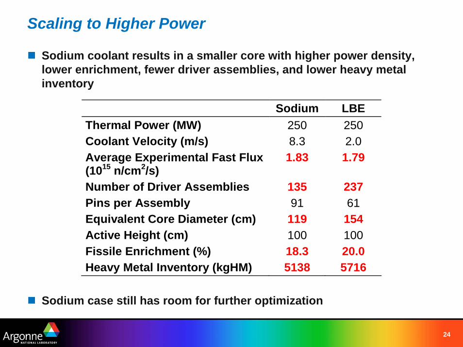
Sodium coolant results in a smaller core with higher power density, lower enrichment, fewer driver assemblies, and lower heavy metalinventory
Sodium case still has room for further optimization
Sodium LBE Thermal Power (MW) 250 250 Coolant Velocity (m/s) 8.3 2.0 Average Experimental Fast Flux (1015 n/cm2/s)
1.83 1.79
Number of Driver Assemblies 135 237 Pins per Assembly 91 61 Equivalent Core Diameter (cm) 119 154 Active Height (cm) 100 100 Fissile Enrichment (%) 18.3 20.0 Heavy Metal Inventory (kgHM) 5138 5716
25
Coolant ActivationCoolant activation results in radioactive isotopes circulating through the primary loop.– Helium yields no activation products unless impurities are present.– Sodium: 23Na(n,γ)24N (t½ = 15 hours)– LBE: 209Bi(n,γ)210Bi, 210Bi → 210Po (t½ = 138 days)
Operationally, this requires shielding for primary components.Po-210 represents a significant biological hazard, requiring a leak-proof system.– PbPo(s) + H2O = PbO + H2Po(g) (volatile alpha-emitting aerosol)
Estimates of cool-down time to meet the IAEA “exemption” criteria (to be freely used for other industrial purposes):– Sodium (pure): ~7 years– Sodium (with impurities): 50-100 years– LBE: ~100,000 years
Experience exists for processing large quantities of primary sodium coolant for disposal (EBR-II).
26
Passive Safety (Liquid Metals)Heat capacity and high thermal conductivity of liquid-metal coolants provides large thermal inertia against system heating during loss-of-flow accidents.– Combined with favorable reactivity feedback (core design/fuel choice)
sufficient cooling is available to support passive shutdown.– Full-power unprotected loss of flow and loss of heat sink accidents
demonstrated in EBR-II in 1986. Similar tests (at 50% power) demonstrated passive response in FFTF
Response of lead/LBE systems to seismic events will pose design challenges.– For medium-sized plant, one can expect primary coolant alone to weigh
~10,000 metric tons.– Structural design of primary system becomes a significant challenge.
27
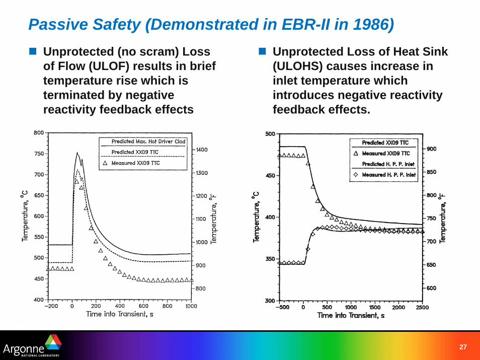
Passive Safety (Demonstrated in EBR-II in 1986)Unprotected (no scram) Loss of Flow (ULOF) results in brief temperature rise which is terminated by negative reactivity feedback effects
Unprotected Loss of Heat Sink (ULOHS) causes increase in inlet temperature which introduces negative reactivity feedback effects.
28
Passive Safety (Helium-Cooled Fast Reactor)In gas-cooled thermal reactors, graphite moderator provides a large heat capacity against excessive temperature rises. Not present in a fast reactor.Low thermal conductivity of helium coolant minimizes thermal shock during transients.– Thermal transients do not propagate to structural materials rapidly. Heat
is deposited in the fuel.– Despite minimal thermal shock, power-to-flow mismatches may be a
significant safety concern for gas-cooled fast reactors.GFR relies on secondary vessel/containment to limit pressure loss.– May be able to support decay heat removal, but not full-power
transients.– Adequate decay heat removal may not be possible under loss of
pressure scenarios.
29
Coolant CostDirect cost– Sodium: On a volume basis, it is generally the cheapest of all metals,
and is among the most abundant elements in the earth’s crust. 2006 price from DuPont (reactor grade/Niapure™) is $1.58/lb ($3400/m3).
– Lead: 2005 USGS, 43 – 61 ¢/lb ($15,000/m3).– Bismuth: U.S. ceased domestic production in 1997 and is highly
dependent on imports. By the end of 2005, USGS-tracked price had increased to >$4/pound ($86,000/m3).
– The Helium Privatization Act of 1996 mandates the price of helium. In 2005, Government price was 1.965 $/m3. Private prices ranged from 2.42 to 2.63 $/m3. At 85 atm, this is roughly $220/m3.
Indirect costs– Coolant chemistry/purification, inventory makeup (helium).– Pumping requirements.– Core and primary system size.– Component lifetime.– Passive safety and safety-related systems.
30
Other ConsiderationsComponent Technology R&D– Regardless of coolant, component testing will be required.– 50+ years of sodium component development, testing, and operation.
Fuel handling– Opaqueness of sodium and lead/LBE affects fuel handling.– Need to maintain pressure boundary with helium also affects fuel
handling.– Must be able to remove residual coolant from spent fuel or test
assemblies.– Significant experience exists for “washing” sodium from spent fuel with
steam or moist air.– Removing LBE from spent fuel may require an acidic “brew” or boiling in
glycerin. Sodium may be used, but it will also remove surface oxides.
31
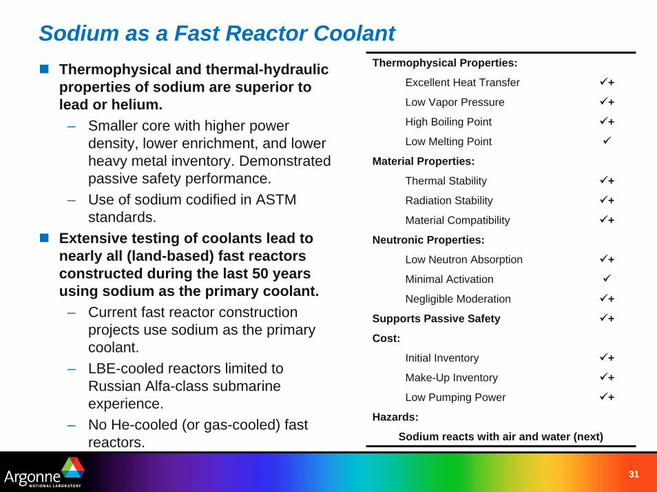
Sodium as a Fast Reactor CoolantThermophysical Properties:
Excellent Heat Transfer +
Low Vapor Pressure +
High Boiling Point +
Low Melting Point
Material Properties:
Thermal Stability +
Radiation Stability +
Material Compatibility +
Neutronic Properties:
Low Neutron Absorption +
Minimal Activation
Negligible Moderation +
Supports Passive Safety +
Cost:
Initial Inventory +
Make-Up Inventory +
Low Pumping Power +
Hazards:
Sodium reacts with air and water (next)
Thermophysical and thermal-hydraulic properties of sodium are superior to lead or helium.
– Smaller core with higher power density, lower enrichment, and lower heavy metal inventory. Demonstrated passive safety performance.
– Use of sodium codified in ASTM standards.
Extensive testing of coolants lead to nearly all (land-based) fast reactors constructed during the last 50 years using sodium as the primary coolant.
– Current fast reactor construction projects use sodium as the primary coolant.
– LBE-cooled reactors limited to Russian Alfa-class submarine experience.
– No He-cooled (or gas-cooled) fast reactors.

32
Sodium Reactivity with Air and Water
33
Sodium Reactivity with AirBurning reaction is characterized by a zone of small (few cm) flames at the sodium-air interface, formation of Na2O on the surface, and vigorous emission of oxide fumes.Sodium reaction with air is slow and causes relatively low heat release– Sodium has a high latent heat of vaporization and high boiling
temperature.• This results in a low evaporation rate during combustion.• Gasoline will burn approximately 4 times faster than sodium
– Sodium-air heat of reaction is one-fourth that of burning gasoline.• Energy released during sodium burning is approximately a factor of
15 lower than in the case of gasoline. – In one series of tests, temperature 1 meter above a 1 square meter pool
of burning sodium was less than 100°C.– For gasoline, the flame zone extended as high as 4 meters and the
average temperature 2 meters above the pool exceeded 600°C.
34
Sodium Reactivity with AirSodium aerosols (NaO and Na2O) react with air (including water vapor and CO2) to produce NaOH, and Na2CO3.– Production of NaOH takes a few seconds after particle formation.– Na2CO3 formation can take several minutes.
Aerosols deposit on the floor, walls, and ceiling.– Aerosol particles can cause equipment damage (electrical and
instrumentation)– Highly toxic
Sodium leaks can be detected through gas sampling techniques– Ability for detection means leaks can be readily identified.
35
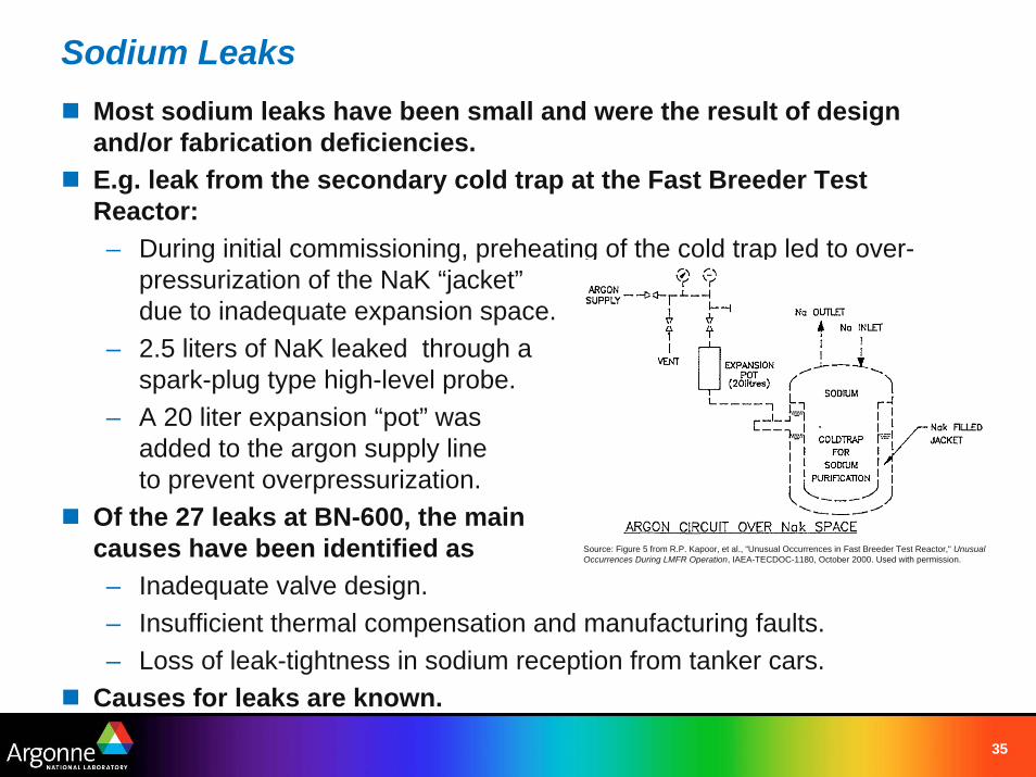
Sodium LeaksMost sodium leaks have been small and were the result of design and/or fabrication deficiencies.E.g. leak from the secondary cold trap at the Fast Breeder Test Reactor:– During initial commissioning, preheating of the cold trap led to over-
pressurization of the NaK “jacket”due to inadequate expansion space.
– 2.5 liters of NaK leaked through a spark-plug type high-level probe.
– A 20 liter expansion “pot” was added to the argon supply line to prevent overpressurization.
Of the 27 leaks at BN-600, the main causes have been identified as– Inadequate valve design.– Insufficient thermal compensation and manufacturing faults.– Loss of leak-tightness in sodium reception from tanker cars.
Causes for leaks are known.
Source: Figure 5 from R.P. Kapoor, et al., “Unusual Occurrences in Fast Breeder Test Reactor," Unusual Occurrences During LMFR Operation, IAEA-TECDOC-1180, October 2000. Used with permission.
36
Significant Sodium Leaks *
BN-600– 1981: Flange joint failure in SG valve seal (300 kg)– 1990: Manufacturing defect in SG drain pipeline (600 kg)– 1993: Thermal expansion induced failure in primary sodium purification
system (1000 kg, ~10 Ci)– 1994: Staff error, pipeline cutting before sodium was frozen (650 kg)
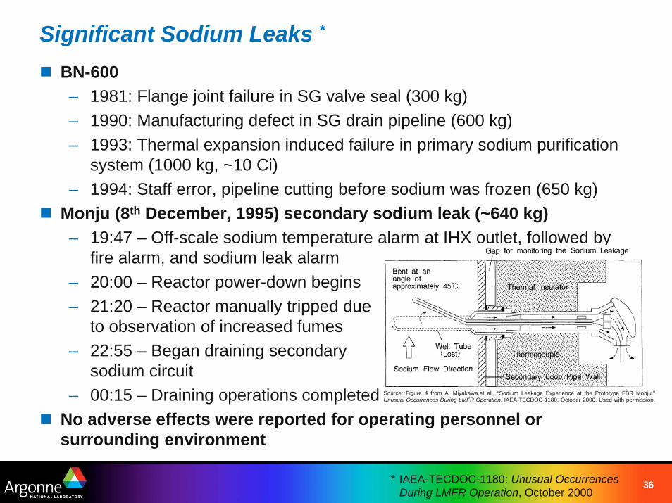
Monju (8th December, 1995) secondary sodium leak (~640 kg)– 19:47 – Off-scale sodium temperature alarm at IHX outlet, followed by
fire alarm, and sodium leak alarm– 20:00 – Reactor power-down begins– 21:20 – Reactor manually tripped due
to observation of increased fumes– 22:55 – Began draining secondary
sodium circuit– 00:15 – Draining operations completed
No adverse effects were reported for operating personnel or surrounding environment
* IAEA-TECDOC-1180: Unusual Occurrences During LMFR Operation, October 2000
Source: Figure 4 from A. Miyakawa,et al., “Sodium Leakage Experience at the Prototype FBR Monju," Unusual Occurrences During LMFR Operation, IAEA-TECDOC-1180, October 2000. Used with permission.
37
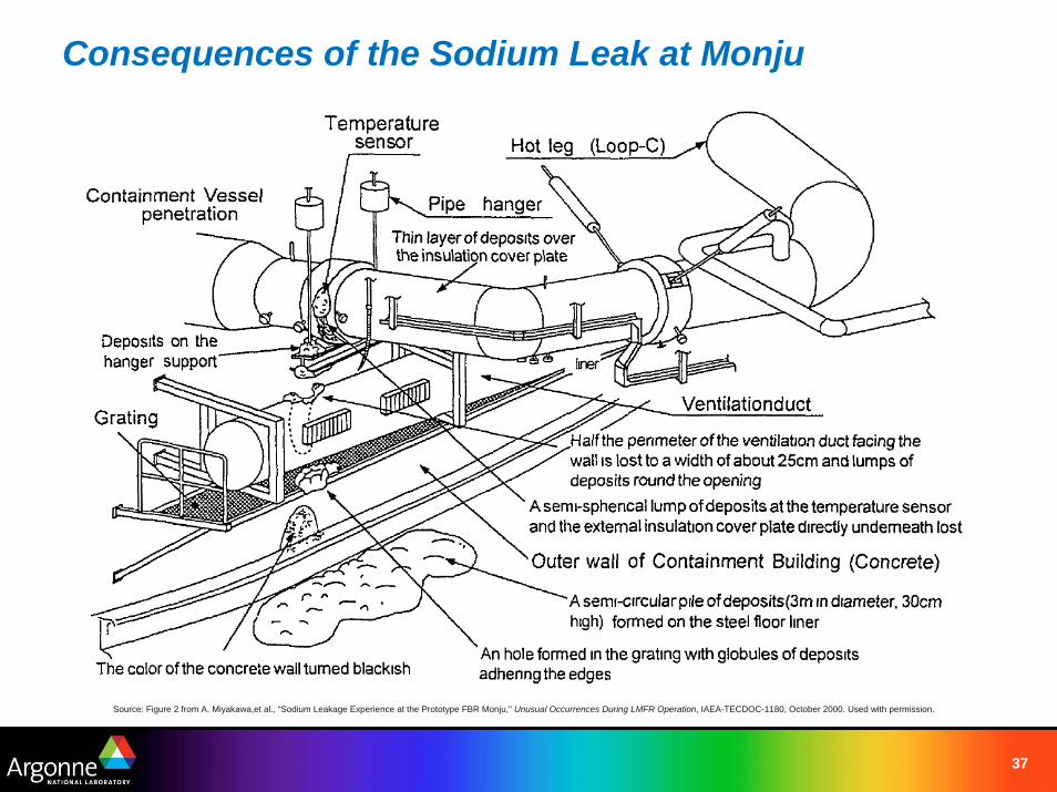
Consequences of the Sodium Leak at Monju
Source: Figure 2 from A. Miyakawa,et al., “Sodium Leakage Experience at the Prototype FBR Monju," Unusual Occurrences During LMFR Operation, IAEA-TECDOC-1180, October 2000. Used with permission.
38
Sodium Reactivity with WaterSodium-water chemical interactions take place in two stages.In the first stage, the reaction proceeds at a high rate with release of gaseous hydrogen:
Na + H2O = NaOH + ½ H2 + 140 kJ/mole
In the second stage, chemical interaction takes place between the products of the first stage and excess sodium:
2 Na + NaOH = Na2O + NaHNa + ½ H2 = NaH
Hydrogen detection plays a key role in leak detection– Diffusion method uses a metal membrane permeable to hydrogen.– E.g. diffusion of hydrogen through a nickel membrane into a vacuum
cavity coupled to a magnetic discharge pump.– Capable of detecting 10 – 30 gram water leak into 100 tons of secondary
sodium.Acoustic detection techniques are also being developed.
39
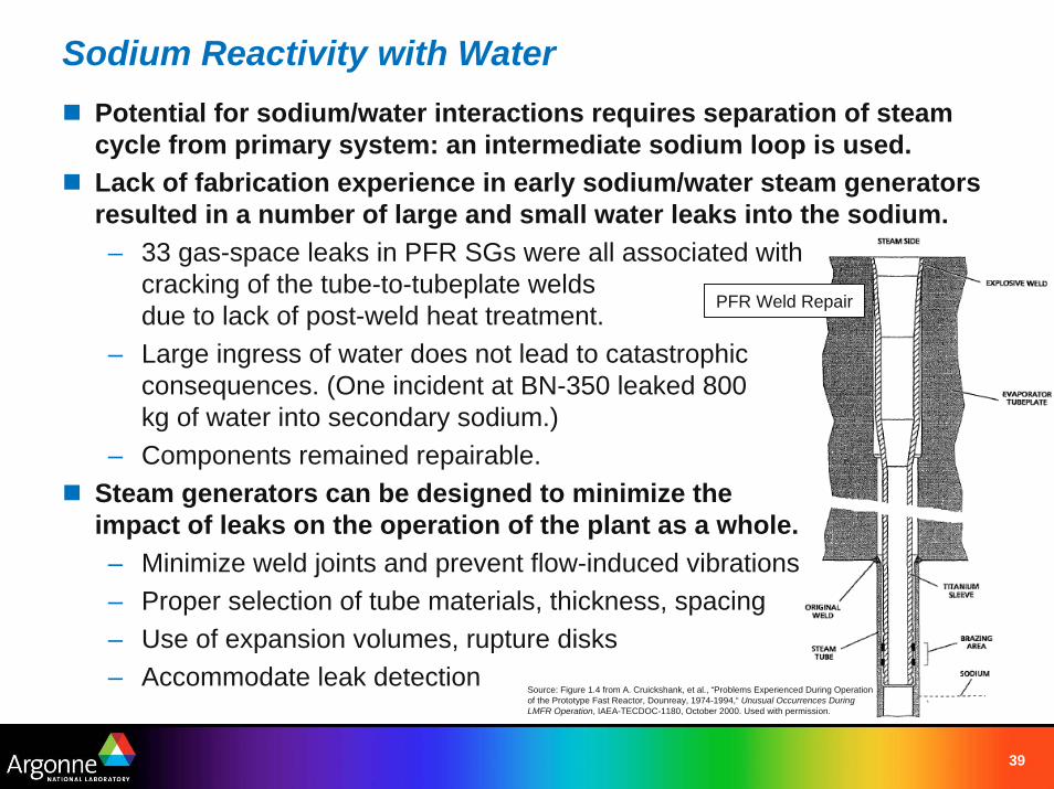
Sodium Reactivity with WaterPotential for sodium/water interactions requires separation of steam cycle from primary system: an intermediate sodium loop is used.Lack of fabrication experience in early sodium/water steam generators resulted in a number of large and small water leaks into the sodium.– 33 gas-space leaks in PFR SGs were all associated with
cracking of the tube-to-tubeplate welds due to lack of post-weld heat treatment.
– Large ingress of water does not lead to catastrophic consequences. (One incident at BN-350 leaked 800 kg of water into secondary sodium.)
– Components remained repairable.Steam generators can be designed to minimize the impact of leaks on the operation of the plant as a whole.– Minimize weld joints and prevent flow-induced vibrations– Proper selection of tube materials, thickness, spacing– Use of expansion volumes, rupture disks– Accommodate leak detection
PFR Weld Repair
Source: Figure 1.4 from A. Cruickshank, et al., “Problems Experienced During Operation of the Prototype Fast Reactor, Dounreay, 1974-1994,“ Unusual Occurrences During LMFR Operation, IAEA-TECDOC-1180, October 2000. Used with permission.
40
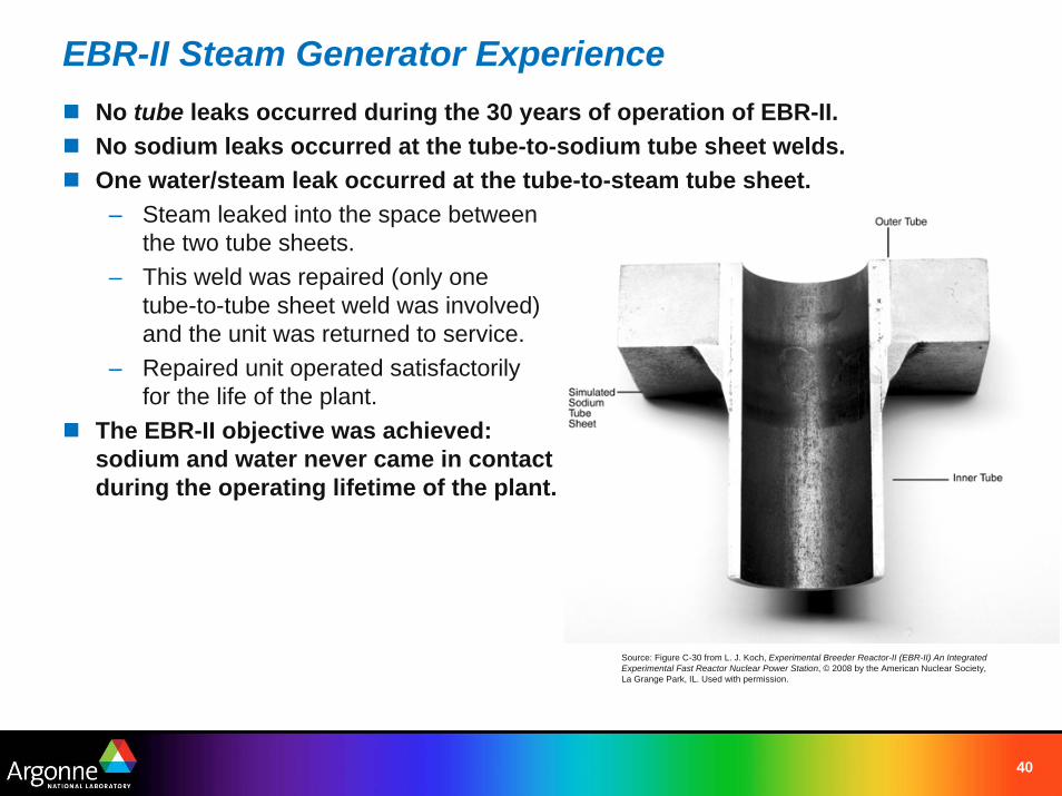
EBR-II Steam Generator ExperienceNo tube leaks occurred during the 30 years of operation of EBR-II.No sodium leaks occurred at the tube-to-sodium tube sheet welds.One water/steam leak occurred at the tube-to-steam tube sheet.
– Steam leaked into the space between the two tube sheets.
– This weld was repaired (only one tube-to-tube sheet weld was involved) and the unit was returned to service.
– Repaired unit operated satisfactorily for the life of the plant.
The EBR-II objective was achieved: sodium and water never came in contact during the operating lifetime of the plant.
Source: Figure C-30 from L. J. Koch, Experimental Breeder Reactor-II (EBR-II) An Integrated Experimental Fast Reactor Nuclear Power Station, © 2008 by the American Nuclear Society, La Grange Park, IL. Used with permission.
41
Impact of Coolant on SFR and LWR Differences
42
Coolant Choice Affects Design DifferencesThe choice of sodium has broad consequences in reactor design– Absence of high pressure in the primary system– Higher operating temperatures with significant thermal margins– More compact fuel assembly designs– Incorporation of an intermediate loop– Different arrangements for fuel handling
43
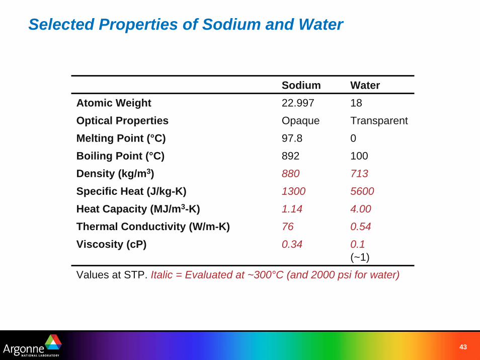
Selected Properties of Sodium and Water
Sodium WaterAtomic Weight 22.997 18Optical Properties Opaque TransparentMelting Point (°C) 97.8 0
Heat Capacity (MJ/m3-K) 1.14 4.00Thermal Conductivity (W/m-K) 76 0.54Viscosity (cP) 0.34 0.1
(~1)Values at STP. Italic = Evaluated at ~300°C (and 2000 psi for water)
Boiling Point (°C) 892 100Density (kg/m3) 880 713Specific Heat (J/kg-K) 1300 5600
44
Sodium Allows Operation at Low System PressureWhile PWRs operate at system pressures in excess of 2000 psi, the inert cover gas in a sodium-cooled fast reactor is near atmospheric pressure.This difference impacts several design features:– Vessel Thickness: PWR ~10 inches, SFR ~ 1 inch– No need for pressurization of SFR fuel pins.
Low system pressure offers advantages in terms of safety:– Minimal pressure loading on the coolant boundary.– In a high-pressure system, coolant pipe breaks are a concern.– In a low-pressure system, coolant leaks are unlikely to propagate to a
large-scale failure.– No need for high-pressure injection cooling.
45
Sodium Provides a Large Margin to Coolant Boiling
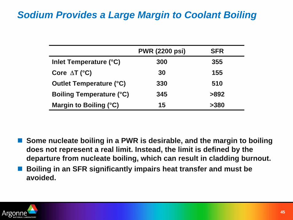
Some nucleate boiling in a PWR is desirable, and the margin to boiling does not represent a real limit. Instead, the limit is defined by the departure from nucleate boiling, which can result in cladding burnout.Boiling in an SFR significantly impairs heat transfer and must be avoided.
PWR (2200 psi) SFRInlet Temperature (°C) 300 355Core ΔT (°C) 30 155
Boiling Temperature (°C) 345 >892Outlet Temperature (°C) 330 510
Margin to Boiling (°C) 15 >380
46
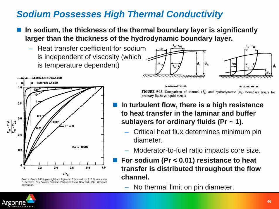
Sodium Possesses High Thermal ConductivityIn sodium, the thickness of the thermal boundary layer is significantly larger than the thickness of the hydrodynamic boundary layer.– Heat transfer coefficient for sodium
is independent of viscosity (which is temperature dependent)
In turbulent flow, there is a high resistance to heat transfer in the laminar and buffer sublayers for ordinary fluids (Pr ~ 1).– Critical heat flux determines minimum pin
diameter.– Moderator-to-fuel ratio impacts core size.
For sodium (Pr < 0.01) resistance to heat transfer is distributed throughout the flow channel.– No thermal limit on pin diameter.
Source: Figure 9-15 (upper right) and Figure 9-16 (above) from A. E. Waltar and A. B. Reynolds, Fast Breeder Reactors, Pergamon Press, New York, 1981. Used with permission.
47
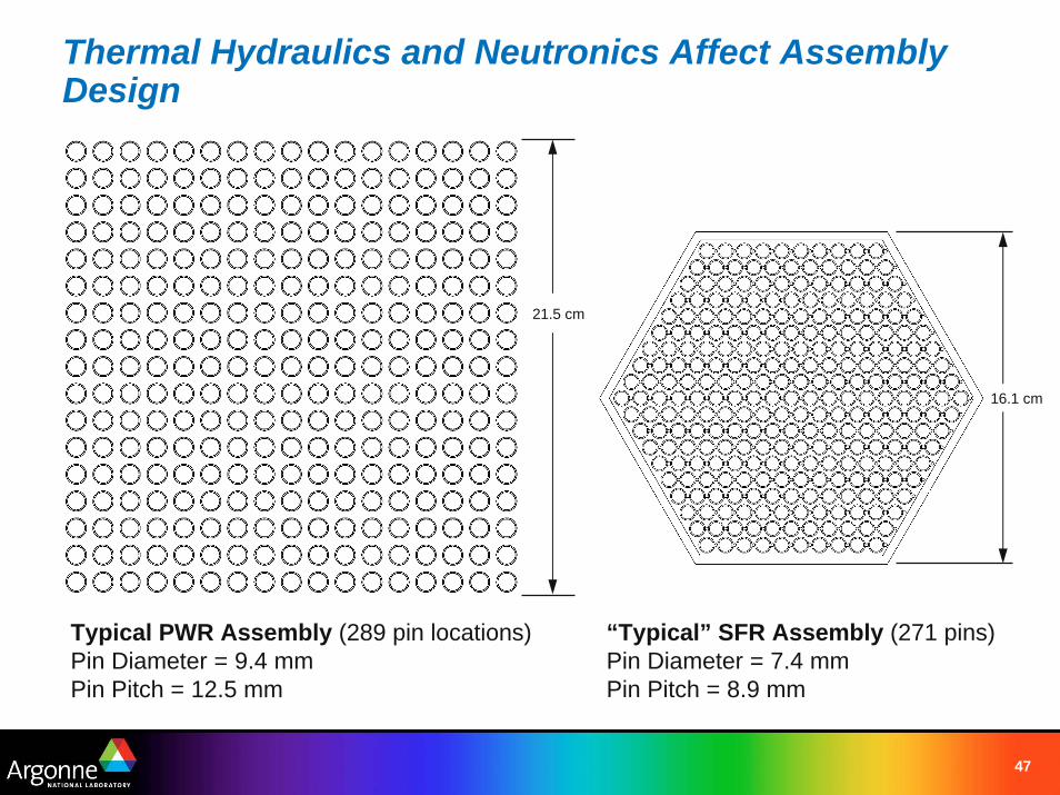
Thermal Hydraulics and Neutronics Affect Assembly Design
Typical PWR Assembly (289 pin locations)Pin Diameter = 9.4 mmPin Pitch = 12.5 mm
“Typical” SFR Assembly (271 pins)Pin Diameter = 7.4 mmPin Pitch = 8.9 mm
16.1 cm
21.5 cm
48
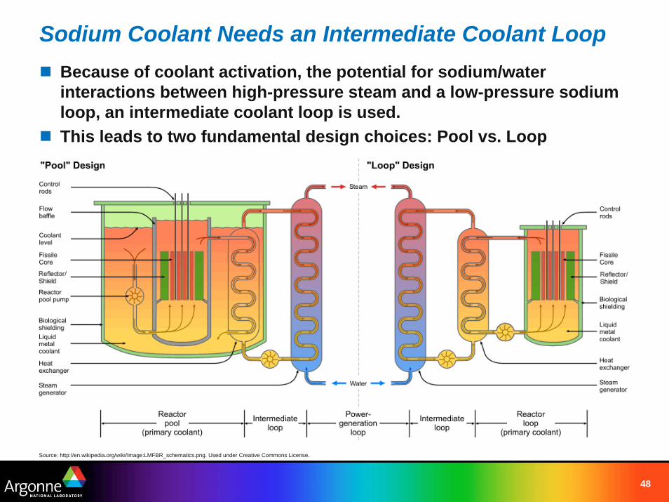
Sodium Coolant Needs an Intermediate Coolant LoopBecause of coolant activation, the potential for sodium/water interactions between high-pressure steam and a low-pressure sodium loop, an intermediate coolant loop is used.This leads to two fundamental design choices: Pool vs. Loop
Source: http://en.wikipedia.org/wiki/Image:LMFBR_schematics.png. Used under Creative Commons License.
49
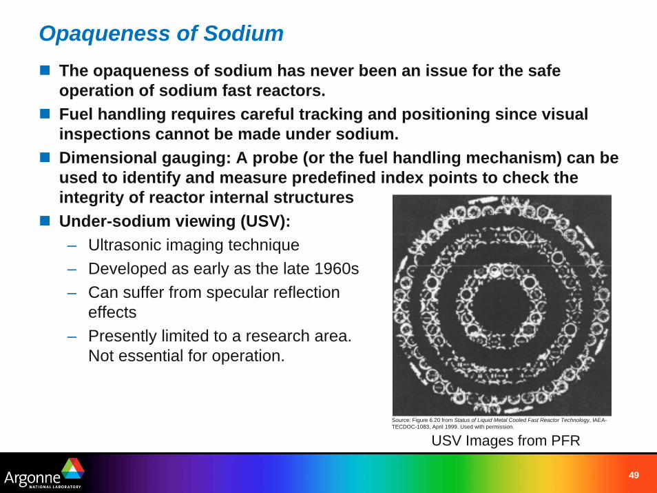
Opaqueness of SodiumThe opaqueness of sodium has never been an issue for the safe operation of sodium fast reactors.Fuel handling requires careful tracking and positioning since visual inspections cannot be made under sodium.Dimensional gauging: A probe (or the fuel handling mechanism) can be used to identify and measure predefined index points to check the integrity of reactor internal structuresUnder-sodium viewing (USV):– Ultrasonic imaging technique– Developed as early as the late 1960s– Can suffer from specular reflection
effects– Presently limited to a research area.
Not essential for operation.
USV Images from PFRSource: Figure 6.20 from Status of Liquid Metal Cooled Fast Reactor Technology, IAEA-TECDOC-1083, April 1999. Used with permission.
50
SummaryExtensive testing of a wide variety of coolants in the 1950s and 1960s.Nearly all fast reactors constructed have used sodium coolant.– 50+ years of sodium component development, testing, and operation. – Current fast reactor construction projects also use sodium.– Very limited experience with LBE coolant, and no experience with lead
or helium-cooled fast reactors.Thermophysical and thermal-hydraulic properties of sodium are superior to lead or helium.– Smaller core with higher power density, lower enrichment, and lower
heavy metal inventory.– Use of sodium codified in ASTM standards.
Issues of sodium reactivity must be addressed through proper component design, fabrication, and testing.There are important differences in reactor design introduced by the use of sodium.– Low system pressure, high thermal conductivity, large safety margins.– Demonstrated capability for passive shutdown and decay heat removal.