soft starters-2
TRANSCRIPT
8/12/2019 Soft Starters-2
http://slidepdf.com/reader/full/soft-starters-2 1/20
Volume 11—Vehicle and Commercial Controls CA08100013E—November 2012 www.eaton.com V11-T6-1
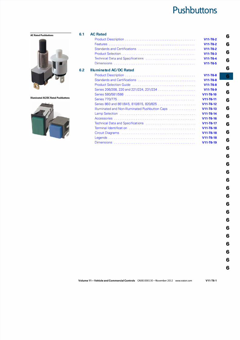
Pushbuttons
AC Rated Pushbuttons
Illuminated AC/DC Rated Pushbuttons
6.1 AC Rated
Product Description . . . . . . . . . . . . . . . . . . . . . . . . . . . . . . . . . . . . . . . V11-T6-2
Features . . . . . . . . . . . . . . . . . . . . . . . . . . . . . . . . . . . . . . . . . . . . . . . . V11-T6-2
Standards and Certifications . . . . . . . . . . . . . . . . . . . . . . . . . . . . . . . . V11-T6-2
Product Selection . . . . . . . . . . . . . . . . . . . . . . . . . . . . . . . . . . . . . . . . . V11-T6-3
Technical Data and Specifications . . . . . . . . . . . . . . . . . . . . . . . . . . . . V11-T6-4
Dimensions . . . . . . . . . . . . . . . . . . . . . . . . . . . . . . . . . . . . . . . . . . . . . V11-T6-5
6.2 Illuminated AC/DC Rated
Product Description . . . . . . . . . . . . . . . . . . . . . . . . . . . . . . . . . . . . . . . V11-T6-8
Standards and Certifications . . . . . . . . . . . . . . . . . . . . . . . . . . . . . . . . V11-T6-8
Product Selection Guide . . . . . . . . . . . . . . . . . . . . . . . . . . . . . . . . . . . V11-T6-8
Series 206/208, 220 and 221/224, 231/234 . . . . . . . . . . . . . . . . . . . . . V11-T6-9
Series 580/581/586 . . . . . . . . . . . . . . . . . . . . . . . . . . . . . . . . . . . . . . . V11-T6-10
Series 770/775 . . . . . . . . . . . . . . . . . . . . . . . . . . . . . . . . . . . . . . . . . . . V11-T6-11
Series 860 and 861/845, 810/815, 820/825 . . . . . . . . . . . . . . . . . . . . . V11-T6-12
Illuminated and Non-Illuminated Pushbutton Caps . . . . . . . . . . . . . . . V11-T6-13
Lamp Selection . . . . . . . . . . . . . . . . . . . . . . . . . . . . . . . . . . . . . . . . . . V11-T6-14
Accessories . . . . . . . . . . . . . . . . . . . . . . . . . . . . . . . . . . . . . . . . . . . . . V11-T6-16
Technical Data and Specifications . . . . . . . . . . . . . . . . . . . . . . . . . . . . V11-T6-17
Terminal Identification . . . . . . . . . . . . . . . . . . . . . . . . . . . . . . . . . . . . . V11-T6-18
Circuit Diagrams . . . . . . . . . . . . . . . . . . . . . . . . . . . . . . . . . . . . . . . . . V11-T6-18
Legends . . . . . . . . . . . . . . . . . . . . . . . . . . . . . . . . . . . . . . . . . . . . . . . . V11-T6-18
Dimensions . . . . . . . . . . . . . . . . . . . . . . . . . . . . . . . . . . . . . . . . . . . . . V11-T6-19
8/12/2019 Soft Starters-2
http://slidepdf.com/reader/full/soft-starters-2 2/20
V11-T6-2 Volume 11—Vehicle and Commercial Controls CA08100013E—November 2012 www.eaton.com
6
6
6
6
6
6
6
6
6
6
6
6
6
6
6
6
6
6
6
6
6
6
6
6
6
6
6
6
6
6
6.1 Pushbuttons
AC Rated
AC Rated ContentsDescription Page
AC Rated
Product Selection . . . . . . . . . . . . . . . . . . . . . . . V11-T6-3
Technical Data and Specifications . . . . . . . . . . V11-T6-4
Dimensions . . . . . . . . . . . . . . . . . . . . . . . . . . . V11-T6-5
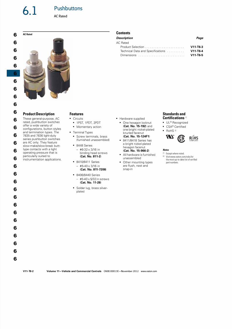
Product DescriptionThese general-purpose, ACrated, pushbutton switchesoffer a wide variety ofconfigurations, button stylesand termination types. The7835 and 7836 light-dutyseries pushbutton switchesare AC only. They featureslow-make/slow-break butt-type contacts with a lightoperating pressure that isparticularly suited toinstrumentation applications.
Features● Circuits
● 1PST, 1PDT, 2PDT● Momentary action
● Terminal Types● Screw terminals, brass
(furnished unassembled)
● 8448 Series
– #6-32 x 3/16 inbinding head screws(Cat. No. 811-2)
● 8410/8411 Series
– #5-40 x 3/16 in(Cat. No. 811-7206)
● 8406/8440 Series
– #5-40 x 5/32 in screws(Cat. No. 11-26)
● Solder lug, brass silver-plated
● Hardware supplied● One hexagon locknut
(Cat. No. 15-192) andone bright nickel-platedknurled facenut(Cat. No. 15-124F1)
● 8411/8418 Series hasa bright nickel-platedhexagon facenut(Cat. No. 15-966-2)
● All hardware is furnishedunassembled
● Other mounting typesare flush, nest andsnap-in
Standards andCertifications 1
● UL® Recognized● CSA® Certified● RoHS 2
Notes 1 Except where noted.2 Visit www.eaton.com/vcbu for
the most up-to-date list of verifiedpart numbers.
8/12/2019 Soft Starters-2
http://slidepdf.com/reader/full/soft-starters-2 3/20
Volume 11—Vehicle and Commercial Controls CA08100013E—November 2012 www.eaton.com V11-T6-3
6.1Pushbuttons
AC Rated
Product SelectionNon-Illuminated
Light-Duty, Momentary Contact
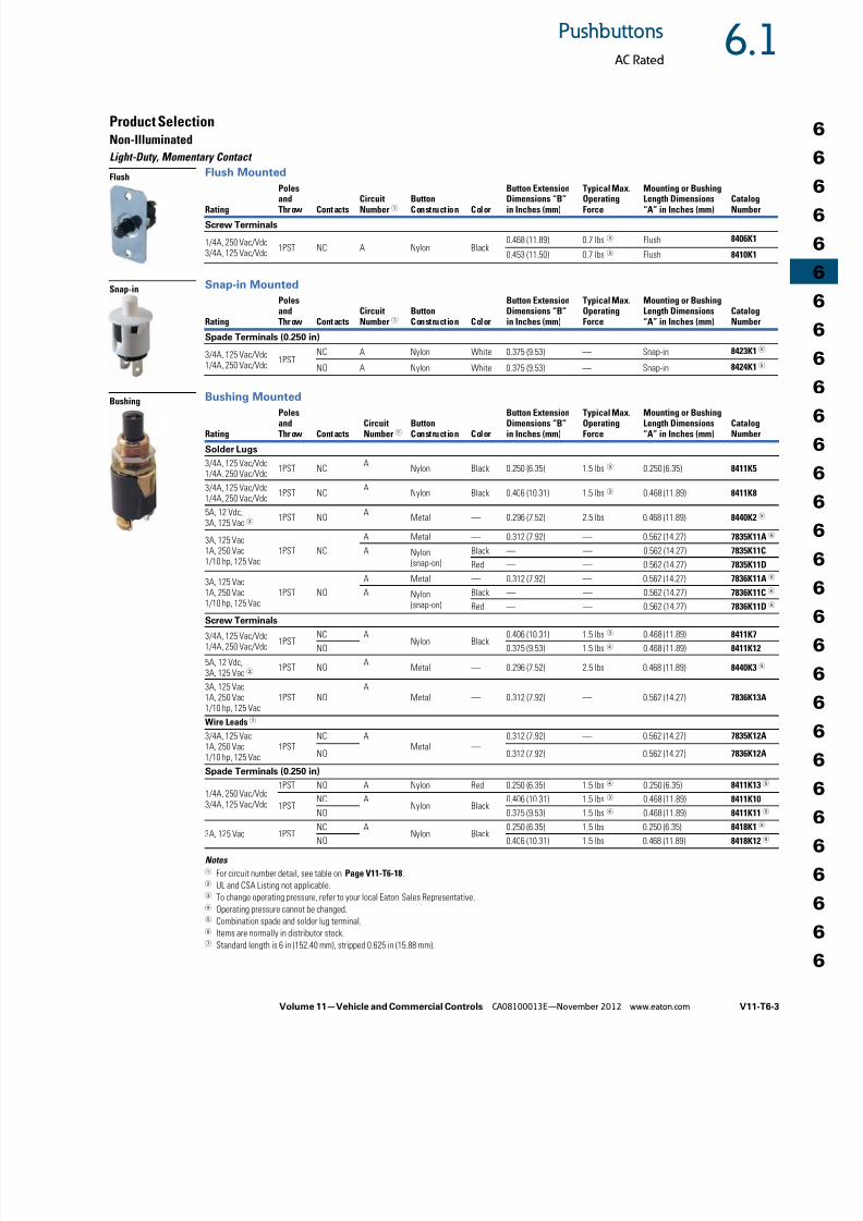
Flush Mounted
Snap-in Mounted
Bushing Mounted
Notes 1 For circuit number detail, see table on Page V11-T6-18.2 UL and CSA Listing not applicable.3 To change operating pressure, refer to your local Eaton Sales Representative.4 Operating pressure cannot be changed.5 Combination spade and solder lug terminal.6 Items are normally in distributor stock.7 Standard length is 6 in (152.40 mm), stripped 0.625 in (15.88 mm).
Rating
Poles
andThr ow Cont acts CircuitNumber 1 ButtonConstruction Color
Button Extension
Dimensions “B”in Inches (mm)
Typical Max.
OperatingForce
Mounting or Bushing
Length Dimensions“A” in Inches (mm) CatalogNumber
Screw Terminals
1/4A, 250 Vac/Vdc3/4A, 125 Vac/Vdc
1PST NC A Nylon Black0.468 (11.89) 0.7 lbs3 Flush 8406K1
0.453 (11.50) 0.7 lbs3 Flush 8410K1
Rating
PolesandThr ow Cont acts
CircuitNumber 1
ButtonConstruction Color
Button ExtensionDimensions “B”in Inches (mm)
Typical Max.OperatingForce
Mounting or BushingLength Dimensions“A” in Inches (mm)
CatalogNumber
Spade Terminals (0.250 in)
3/4A, 125 Vac/Vdc1/4A, 250 Vac/Vdc
1PSTNC A Nylon White 0.375 (9.53) — Snap-in 8423K15
NO A Nylon White 0.375 (9.53) — Snap-in 8424K15
Rating
PolesandThr ow Cont acts
CircuitNumber 1
ButtonConstruction Color
Button ExtensionDimensions “B”in Inches (mm)
Typical Max.OperatingForce
Mounting or BushingLength Dimensions“A” in Inches (mm)
CatalogNumber
Solder Lugs
3/4A, 125 Vac/Vdc1/4A, 250 Vac/Vdc
1PST NCA
Nylon Black 0.250 (6.35) 1.5 lbs3 0.250 (6.35) 8411K5
3/4A, 125 Vac/Vdc1/4A, 250 Vac/Vdc
1PST NCA
Nylon Black 0.406 (10.31) 1.5 lbs3 0.468 (11.89) 8411K8
5A, 12 Vdc,3A, 125 Vac 2
1PST NOA
Metal — 0.296 (7.52) 2.5 lbs 0.468 (11.89) 8440K25
3A, 125 Vac1A, 250 Vac1/10 hp, 125 Vac
1PST NC
A Metal — 0.312 (7.92) — 0.562 (14.27) 7835K11A6
A Nylon(snap-on)
Black — — 0.562 (14.27) 7835K11C
Red — — 0.562 (14.27) 7835K11D
3A, 125 Vac1A, 250 Vac1/10 hp, 125 Vac
1PST NO
A Metal — 0.312 (7.92) — 0.562 (14.27) 7836K11A6
A Nylon
(snap-on)
Black — — 0.562 (14.27) 7836K11C6
Red — — 0.562 (14.27) 7836K11D6
Screw Terminals
3/4A, 125 Vac/Vdc1/4A, 250 Vac/Vdc
1PSTNC A
Nylon Black0.406 (10.31) 1.5 lbs3 0.468 (11.89) 8411K7
NO 0.375 (9.53) 1.5 lbs4 0.468 (11.89) 8411K12
5A, 12 Vdc,3A, 125 Vac 2
1PST NOA
Metal — 0.296 (7.52) 2.5 lbs 0.468 (11.89) 8440K35
3A, 125 Vac1A, 250 Vac1/10 hp, 125 Vac
1PST NOA
Metal — 0.312 (7.92) — 0.562 (14.27) 7836K13A
Wire Leads7
3/4A, 125 Vac1A, 250 Vac1/10 hp, 125 Vac
1PSTNC A
Metal —0.312 (7.92) — 0.562 (14.27) 7835K12A
NO 0.312 (7.92) — 0.562 (14.27) 7836K12A
Spade Terminals (0.250 in)
1/4A, 250 Vac/Vdc3/4A, 125 Vac/Vdc
1PST NO A Nylon Red 0.250 (6.35) 1.5 lbs4 0.250 (6.35) 8411K135
1PSTNC A
Nylon Black0.406 (10.31) 1.5 lbs3 0.468 (11.89) 8411K10
NO 0.375 (9.53) 1.5 lbs4 0.468 (11.89) 8411K115
3A, 125 Vac 1PSTNC A
Nylon Black0.250 (6.35) 1.5 lbs 0.250 (6.35) 8418K15
NO 0.406 (10.31) 1.5 lbs 0.468 (11.89) 8418K125
Flush
Snap-in
Bushing
8/12/2019 Soft Starters-2
http://slidepdf.com/reader/full/soft-starters-2 4/20
V11-T6-4 Volume 11—Vehicle and Commercial Controls CA08100013E—November 2012 www.eaton.com
6
6
6
6
6
6
6
6
6
6
6
6
6
6
6
6
6
6
6
6
6
6
6
6
6
6
6
6
6
6
6.1 Pushbuttons
AC Rated
Non-Illuminated
Medium-Duty, Momentary Contact
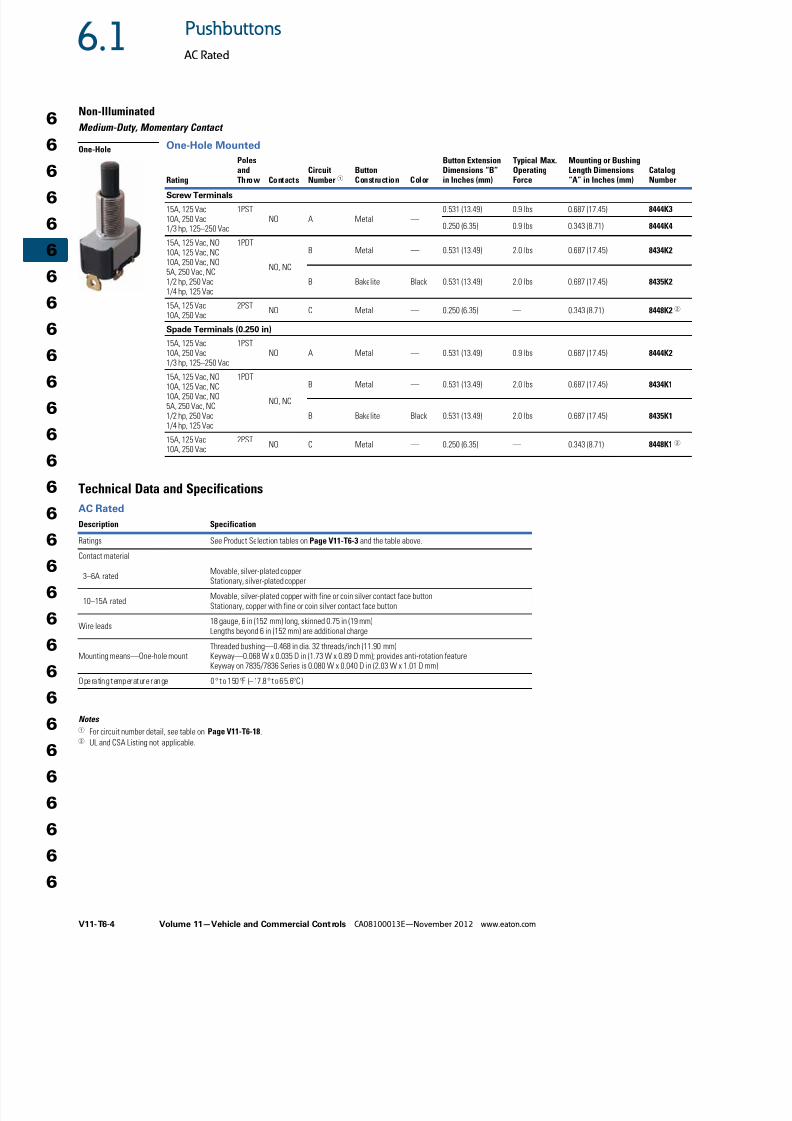
One-Hole Mounted
Technical Data and Specifications
AC Rated
Notes 1 For circuit number detail, see table on Page V11-T6-18.2
UL and CSA Listing not applicable.
Rating
PolesandThrow Contacts
CircuitNumber 1
ButtonConstruction Color
Button ExtensionDimensions “B”in Inches (mm)
Typical Max.OperatingForce
Mounting or BushingLength Dimensions“A” in Inches (mm)
CatalogNumber
Screw Terminals
15A, 125 Vac10A, 250 Vac1/3 hp, 125–250 Vac
1PSTNO A Metal —
0.531 (13.49) 0.9 lbs 0.687 (17.45) 8444K3
0.250 (6.35) 0.9 lbs 0.343 (8.71) 8444K4
15A, 125 Vac, NO10A, 125 Vac, NC10A, 250 Vac, NO5A, 250 Vac, NC1/2 hp, 250 Vac1/4 hp, 125 Vac
1PDT
NO, NC
B Metal — 0.531 (13.49) 2.0 lbs 0.687 (17.45) 8434K2
B Bakelite Black 0.531 (13.49) 2.0 lbs 0.687 (17.45) 8435K2
15A, 125 Vac10A, 250 Vac
2PSTNO C Metal — 0.250 (6.35) — 0.343 (8.71) 8448K22
Spade Terminals (0.250 in)
15A, 125 Vac10A, 250 Vac1/3 hp, 125–250 Vac
1PSTNO A Metal — 0.531 (13.49) 0.9 lbs 0.687 (17.45) 8444K2
15A, 125 Vac, NO10A, 125 Vac, NC10A, 250 Vac, NO5A, 250 Vac, NC1/2 hp, 250 Vac1/4 hp, 125 Vac
1PDT
NO, NC
B Metal — 0.531 (13.49) 2.0 lbs 0.687 (17.45) 8434K1
B Bakelite Black 0.531 (13.49) 2.0 lbs 0.687 (17.45) 8435K1
15A, 125 Vac10A, 250 Vac
2PSTNO C Metal — 0.250 (6.35) — 0.343 (8.71) 8448K12
Description Specification
Ratings See Product Selection tables on Page V11-T6-3 and the table above.
Contact material
3–6A ratedMovable, silver-plated copperStationary, silver-plated copper
10–15A ratedMovable, silver-plated copper with fine or coin silver contact face buttonStationary, copper with fine or coin silver contact face button
Wire leads18 gauge, 6 in (152 mm) long, skinned 0.75 in (19 mm)Lengths beyond 6 in (152 mm) are additional charge
Mounting means—One-hole mountThreaded bushing—0.468 in dia. 32 threads/inch (11.90 mm)Keyway—0.068 W x 0.035 D in (1.73 W x 0.89 D mm); provides anti-rotation featureKeyway on 7835/7836 Series is 0.080 W x 0.040 D in (2.03 W x 1.01 D mm)
Operating temperature range 0° to 150°F (–17.8° to 65.6°C)
One-Hole
8/12/2019 Soft Starters-2
http://slidepdf.com/reader/full/soft-starters-2 5/20
Volume 11—Vehicle and Commercial Controls CA08100013E—November 2012 www.eaton.com V11-T6-5
6.1Pushbuttons
AC Rated
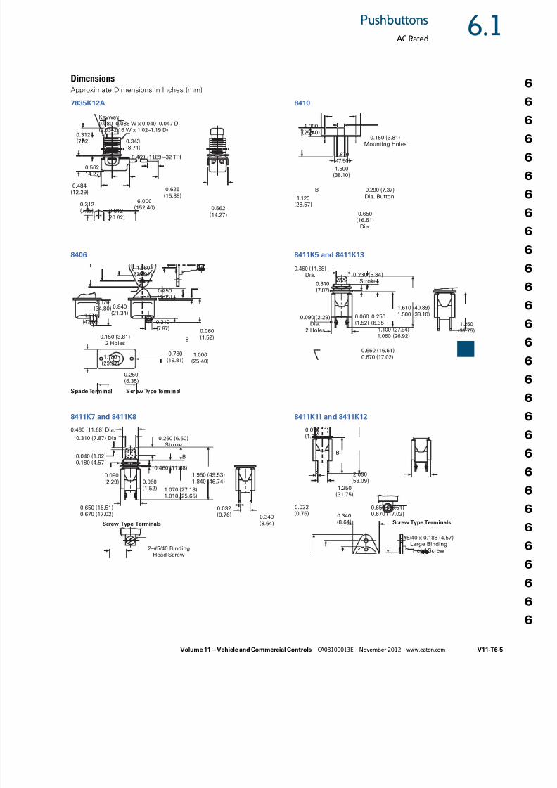
DimensionsApproximate Dimensions in Inches (mm)
7835K12A
8406
8411K7 and 8411K8
8410
8411K5 and 8411K13
8411K11 and 8411K12
6.000(152.40)
0.312(7.92) 0.343
(8.71)
Keyway0.080–0.085 W x 0.040–0.047 D
(2.03–2.16 W x 1.02–1.19 D)
0.312(7.92) 0.812
(20.62)
0.562(14.27)
0.562(14.27)
0.484(12.29)
0.625(15.88)
0.469 (11.89)–32 TPI
0.250(6.35)
1.060(26.92)
Dia.
0.840(21.34)1.870
(47.50)
1.370(34.80)
1.180(29.97)
0.150 (3.81)2 Holes
0.780(19.81)
0.060(1.52)
0.310(7.87)
1.000(25.40)
0.250(6.35)
B
Spade Terminal Screw Type Terminal
0.060(1.52)
0.260 (6.60)Stroke
0.650 (16.51)0.670 (17.02)
1.070 (27.18)1.010 (25.65)
0.310 (7.87) Dia.
0.460 (11.68) Dia.
1.950 (49.53)1.840 (46.74)
0.460 (11.68)
B
0.032(0.76) 0.340
(8.64)
2–#5/40 BindingHead Screw
Screw Type Terminals
0.090(2.29)
0.040 (1.02)0.180 (4.57)
0.650(16.51)
Dia.
1.120(28.57)
1.500(38.10)
1.870(47.50)
1.000
(25.40)
0.290 (7.37)Dia. Button
0.150 (3.81)Mounting Holes
B
1.250(31.75)
0.060(1.52)
0.250(6.35)
0.230 (5.84)Stroke
0.650 (16.51)0.670 (17.02)
1.100 (27.94)1.060 (26.92)
0.310(7.87)
0.460 (11.68)Dia.
1.610 (40.89)1.500 (38.10)
0.090 (2.29)Dia.
2 Holes
1.250(31.75)
0.650 (16.51)0.670 (17.02)
0.032(0.76) 0.340
(8.64)
2.090(53.09)
B
#5/40 x 0.188 (4.57)Large BindingHead Screw
Screw Type Terminals
0.070(1.78)
8/12/2019 Soft Starters-2
http://slidepdf.com/reader/full/soft-starters-2 6/20
V11-T6-6 Volume 11—Vehicle and Commercial Controls CA08100013E—November 2012 www.eaton.com
6
6
6
6
6
6
6
6
6
6
6
6
6
6
6
6
6
6
6
6
6
6
6
6
6
6
6
6
6
6
6.1 Pushbuttons
AC Rated
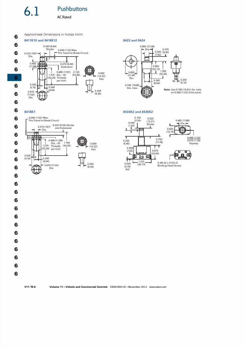
Approximate Dimensions in Inches (mm)
8411K10 and 8418K12
8418K1
8423 and 8424
8434K2 and 8435K2
0.310 (7.87)Dia.
2.120(53.85)1.270
(32.26)
0.670(17.02)
Dia.
0.030(0.76)
0.370 (9.40)Extension
0.460(11.68)
0.340 (8.64)Stroke 0.040 (1.02) Max.
Pre-Travel to Break Circuit
0.340(8.64) 0.250
(6.35)
0.469 (11.91)Dia. –32Threadsper Inch
0.560(14.22)
Hex
1.750(44.45)1.270
(32.26)
0.670 (17.02)Dia.
0.030(0.76)
0.220 (5.59) Strokeand Extension
0.040 (1.02) Max.Pre-Travel to Break Circui t
0.340(8.64)
0.250(6.35)
0.469 (11.89)Dia. –32Threadsper Inch
0.560(14.22)
Hex
0.310 (7.87)Dia.
B
0.240(6.10)
0.340(8.64)
0.740 (18.80)Dia. max.
0.950(24.13)
1.350(34.29)
0.370(9.40)0.300
(7.62)
0.850 (21.59)Dia.
0.850
(21.59)
Dia.
Note: Use 0.780 (19.81) dia. holeon 0.060 (1.52) thick panel.
0.620(15.75)
0.970(24.64)
0.030(0.76)Ref
1.210(30.73)
3–#6-32 x 3/16 LGBinding Head Screw
0.040 (1.02)0.070 (1.78)
Keyway
0.100(2.54)
0.300(7.62)
0.700(17.78)
0.520(13.21)Stroke
0.040(1.02)
0.230(5.95)
0.460 (11.68)Dia.
8/12/2019 Soft Starters-2
http://slidepdf.com/reader/full/soft-starters-2 7/20
Volume 11—Vehicle and Commercial Controls CA08100013E—November 2012 www.eaton.com V11-T6-7
6.1Pushbuttons
AC Rated
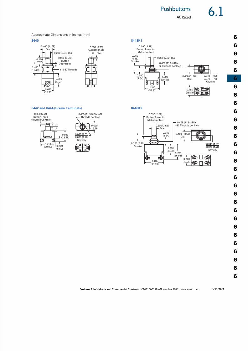
Approximate Dimensions in Inches (mm)
8440
8442 and 8444 (Screw Terminals)
8448K1
8448K2
0.620(15.75)
0.460 (11.68)Dia.
0.230 (5.84) Dia.
0.460(11.68)
0.290(7.37)
0.680(17.27)
0.030 (0.76)to 0.070 (1.78)
Pre-Travel
#15-32 Threads
0.030 (0.76)Button
Depressed
0.620(15.75)
B
A
0.940(23.88)
1.210(30.99) 0.260
(6.60)
0.090 (2.29)
Button Travelto Make Contact
0.040 (1.02)0.070 (1.78)
Keyway
0.469 (11.91) Dia. –32
Threads per Inch
0.750(19.05)
1.200(30.48)
0.250
(6.35)Stroke
0.469 (11.91) Dia.–32 Threads per Inch
0.340(8.64)
0.090 (2.29)Button Travel toMake Contact
1.310(33.27)
0.040 (1.02)0.070 (1.78)
Keyway
0.460 (11.68)Dia.
0.300 (7.62) Dia.
0.469 (11.91) Dia.–32 Threads per Inch
0.460 (11.68)Dia.
0.040 (1.02)0.070 (1.78)
Keyway
0.750(19.05)1.320
(33.53)
0.300 (7.62)Dia.
0.090 (2.29)
Button Travel toMake Contact
0.250 (6.35)Stroke
1.060(26.92)
0.760(19.30)
0.340(8.64)
8/12/2019 Soft Starters-2
http://slidepdf.com/reader/full/soft-starters-2 8/20
V11-T6-8 Volume 11—Vehicle and Commercial Controls CA08100013E—November 2012 www.eaton.com
6
6
6
6
6
6
6
6
6
6
6
6
6
6
6
6
6
6
6
6
6
6
6
6
6
6
6
6
6
6
6.2 Pushbuttons
Illuminated AC/DC Rated
Illuminated AC/DC Rated ContentsDescription Page
Illuminated AC/DC Rated
Catalog Number Selection . . . . . . . . . . . . . . . . V11-T6-9
Lamp Selection . . . . . . . . . . . . . . . . . . . . . . . . V11-T6-14
Accessories . . . . . . . . . . . . . . . . . . . . . . . . . . . V11-T6-16Technical Data and Specifications . . . . . . . . . . V11-T6-17
Terminal Identification . . . . . . . . . . . . . . . . . . . . V11-T6-18
Circuit Diagrams . . . . . . . . . . . . . . . . . . . . . . . . V11-T6-18
Legends . . . . . . . . . . . . . . . . . . . . . . . . . . . . . . V11-T6-18
Dimensions . . . . . . . . . . . . . . . . . . . . . . . . . . . V11-T6-19
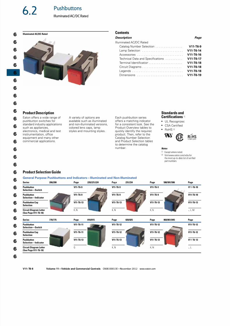
Product DescriptionEaton offers a wide range ofpushbutton switches forstandard industry applicationssuch as appliances,electronics, medical and testinstrumentation, officeequipment and many othercommercial applications.
A variety of options areavailable such as illuminatedand non-illuminated versions,colored lens caps, lampstyles and mounting styles.
Each pushbutton seriesoffers a matching indicatorfor a consistent look. See theProduct Overview tables toquickly identify the requiredproduct. Then, refer to theCatalog Number Selectionand Product Selection tablesto determine the catalognumber.
Standards andCertifications 1
● UL Recognized● CSA Certified● RoHS 2
Notes 1 Except where noted.2 Visit www.eaton.com/vcbu for
the most up-to-date list of verifiedpart numbers.
Product Selection Guide
General Purpose Pushbuttons and Indicators—Illuminated and Non-Illuminated
Series 206/208 Page 220/221/224 Page 231/234 Page 580/581/586 Page
PushbuttonSelection—Switch
V11-T6-9 V11-T6-9 V11-T6-9 V11-T6-10
PushbuttonSelection—Indicator
V11-T6-9 V11-T6-9 V11-T6-9 V11-T6-10
Pushbutton CapSelection
V11-T6-13 V11-T6-13 V11-T6-13 V11-T6-13
Circuit Diagram Letter(See Page V11-T6-18)
K, N K, N K, N J, L, M
Series 770/775 Page 810/815 Page 820/825 Page 860/861/845 Page
PushbuttonSelection—Switch
V11-T6-11 V11-T6-12 V11-T6-12 V11-T6-12
Pushbutton CapSelection
V11-T6-11 V11-T6-12 V11-T6-12 V11-T6-12
PushbuttonSelection—Indicator
V11-T6-13 V11-T6-13 V11-T6-13 V11-T6-13
Circuit Diagram Letter(See Page V11-T6-18)
Q K, N K, N J, L
8/12/2019 Soft Starters-2
http://slidepdf.com/reader/full/soft-starters-2 9/20
Volume 11—Vehicle and Commercial Controls CA08100013E—November 2012 www.eaton.com V11-T6-9
6.2Pushbuttons
Illuminated AC/DC Rated
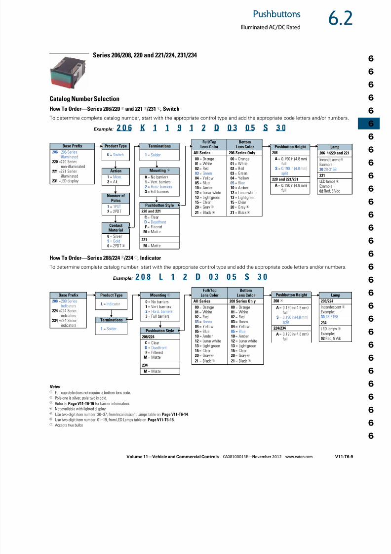
Series 206/208, 220 and 221/224, 231/234
Catalog Number Selection
How To Order—Series 206/220 1 and 221 1 /231 1, Switch
How To Order—Series 208/224 1 /234 1, Indicator
Notes 1 Full cap style does not require a bottom lens code.2 Pole one is silver, pole two is gold.3 Refer to Page V11-T6-16 for barrier information.4 Not available with lighted display.5 Use two-digit item number, 30–37, from Incandescent Lamps table on Page V11-T6-14.6 Use two-digit item number, 01–19, from LED Lamps table on Page V11-T6-15.7 Accepts two bulbs
To determine complete catalog number, start with the appropriate control type and add the appropriate code letters and/or numbers.
2 0 6 K 1 1 9 1 2 D 0 3 0 5 S 3 0
Base Prefix
206 =206 Seriesilluminated
220 =220 Seriesnon-illuminated
221 =221 Seriesilluminated
231 =LED display
Product Type
K = Switch
Action
1 = Mom.
2 = Alt.
Terminations
1 = Solder
Full/TopLens Color
BottomLens Color
All Series 206 Series Only
00 = Orange01 = White02 = Red03 = Green04 = Yellow
05 = Blue10 = Amber12 = Lunar white13 = Light green15 = Clear20 = Gray4
21 = Black4
00 = Orange01 = White02 = Red03 = Green04 = Yellow
05 = Blue10 = Amber12 = Lunar white13 = Light green15 = Clear20 = Gray4
21 = Black4
Pushbutton Height
206
A = 0.190 in (4.8 mm)full
S = 0.190 in (4.8 mm)split
220 and 221/231
A = 0.190 in (4.8 mm)full
Lamp
206 7 /220 and 221
Incandescent5 Example:30 28-3158
231
LED lamps 6 Example:02 Red, 5 Vdc
Example:
Number ofPoles
1 = 1PST 2 = 2PDT
Mounting3
0 = No barriers
1 = Vert. barriers2 = Horiz. barriers3 = Full barriers
ContactMaterial
8 = Silver9 = Gold 6 = 2PDT2
Pushbutton Style
220 and 221
C = ClearD = DeadfrontF = Filtered
M = Matte
231
M = Matte
To determine complete catalog number, start with the appropriate control type and add the appropriate code letters and/or numbers.
2 0 8 L 1 2 D 0 3 0 5 S 3 0
Base Prefix
208 =208 Seriesindicators
224 =224 Seriesindicators
234 =234 Seriesindicators
Product Type
L = Indicator
Terminations
1 = Solder
Full/TopLens Color
BottomLens Color
All Series 208 Series Only
00 = Orange01 = White02 = Red03 = Green04 = Yellow05 = Blue10 = Amber12 = Lunar white13 = Light green15 = Clear20 = Gray4
21 = Black4
00 = Orange01 = White02 = Red03 = Green04 = Yellow05 = Blue10 = Amber12 = Lunar white13 = Light green15 = Clear20 = Gray4
21 = Black4
Pushbutton Height
208 7
A = 0.190 in (4.8 mm)full
S = 0.190 in (4.8 mm)split
224/234
A = 0.190 in (4.8 mm)full
Lamp
208/224
Incandescent5 Example:30 28-3158
234
LED lamps6 Example:02 Red, 5 Vdc
Example:
Mounting 3
0 = No barriers1 = Vert. barriers2 = Horiz. barriers3 = Full barriers
Pushbutton Style
208/224
C = ClearD = DeadfrontF = Filtered
M = Matte
234
M = Matte
8/12/2019 Soft Starters-2
http://slidepdf.com/reader/full/soft-starters-2 10/20
V11-T6-10 Volume 11—Vehicle and Commercial Controls CA08100013E—November 2012 www.eaton.com
6
6
6
6
6
6
6
6
6
6
6
6
6
6
6
6
6
6
6
6
6
6
6
6
6
6
6
6
6
6
6.2 Pushbuttons
Illuminated AC/DC Rated
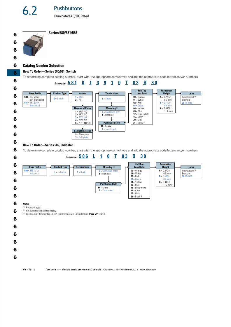
Series 580/581/586
Catalog Number Selection
How To Order—Series 580/581, Switch
How To Order—Series 586, Indicator
Notes 1 Flush with bezel.2 Not available with lighted display.3 Use two-digit item number, 30–37, from Incandescent Lamps table on Page V11-T6-14.
To determine complete catalog number, start with the appropriate control type and add the appropriate code letters and/or numbers.
5 8 1 K 1 3 9 1 0 T 0 3 B 3 0
Base Prefix
580 = 580 Seriesnon-illuminated
581 = 581 Seriesilluminated
Product Type
K = Switch
Action
1 = Mom. 2 = Alt.
Terminations
1 = Solder
Full/TopLens Color
00 = Orange01 = White02 = Red03 = Green
04 = Yellow05 = Blue12 = Lunar white15 = Clear20 = Gray
21 = Black2
PushbuttonHeight
A = 0.270 in(6.9 mm)
B = 0.330 in(8.4 mm)
C = 0.440 in(11.2 mm)
Lamp
Incandescent3 Example:30 28-3158
Example:
Number of Poles1 = 1PST NO2 = 1PST NC3 = 2PST NO4 = 2PST NC5 = 2PST NO/NC
Mounting 10 = Chamfered bezel1 = Flat bezel
Contact Material
5 = Silver plate9 = Gold plate
Pushbutton Style
M = MatteT = Translucent
Pushbutton Style
M = MatteT = Translucent
To determine complete catalog number, start with the appropriate control type and add the appropriate code letters and/or numbers.
5 8 6 L 1 0 T 0 3 B 3 0
Base Prefix
586= 586 Seriesindicators
Product Type
L = Indicator
Terminations
1 = Solder
Full/TopLens Color
00 = Orange01 = White02 = Red03 = Green04 = Yellow05 = Blue12 = Lunar white15 = Clear20 = Gray
21 = Black2
PushbuttonHeight
A = 0.270 in(6.9 mm)
B = 0.330 in(8.4 mm)
C = 0.440 in(11.2 mm)
Lamp
Incandescent3 Example:30 28-3158
Example:
Mounting 1
0 = Chamfered bezel1 = Flat bezel
8/12/2019 Soft Starters-2
http://slidepdf.com/reader/full/soft-starters-2 11/20
Volume 11—Vehicle and Commercial Controls CA08100013E—November 2012 www.eaton.com V11-T6-11
6.2Pushbuttons
Illuminated AC/DC Rated
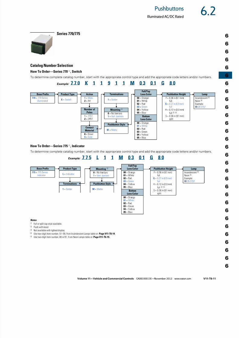
Series 770/775
Catalog Number Selection
How To Order—Series 770 1, Switch
How To Order—Series 775 1, Indicator
Notes 1
Full or split cap style available.2 Flush with bezel.3 Not available with lighted display.4 Use two-digit item number, 51–59, from Incandescent Lamps table on Page V11-T6-14.5 Use two-digit item number, 80 or 81, from Neon Lamps table on Page V11-T6-15.
To determine complete catalog number, start with the appropriate control type and add the appropriate code letters and/or numbers.
7 7 0 K 1 1 9 1 1 M 0 3 0 1 G 8 0
Base Prefix
770 = 770 Seriesilluminated
Product Type
K = Switch
Action
1 = Mom. 2 = Alt.
Terminations
1 = Solder
Full/TopLens Color
00 = Orange01 = White02 = Red03 = Green04 = Yellow
05 = BlueBottom
Lens Color
00 = Orange01 = White02 = Red03 = Green04 = Yellow05 = Blue
Pushbutton Height
F = 0.36 in (9.1 mm)full
G = 0.27 in (6.9 mm)full
H = 0.12 in (3.0 mm)
full2 3
S = 0.36 in (9.1 mm)split
Lamp
Incandescent4 Neon5 Example:80 28-3157
Example:
Number of
Poles1 = 1PDT 2 = 2PDT
Mounting 2
0 = No barriers1 = Vert. barriers
ContactMaterial
8 = Silver9 = Gold
Pushbutton Style
M = Matte
LampIncandescent4 Neon5 Example:80 28-3157
To determine complete catalog number, start with the appropriate control type and add the appropriate code letters and/or numbers.
7 7 5 L 1 1 M 0 3 0 1 G 8 0
Terminations
1 = Solder
Pushbutton HeightF = 0.36 in (9.1 mm)
fullG = 0.27 in (6.9 mm)
fullH = 0.12 in (3.0 mm)
full 2 3
S = 0.36 in (9.1 mm)split
Example:
Mounting 2
0 = No barriers1 = Vert. barriers
Pushbutton Style
M = Matte
Full/Top
Lens Color00 = Orange01 = White02 = Red03 = Green04 = Yellow05 = Blue
BottomLens Color
00 = Orange01 = White02 = Red03 = Green04 = Yellow05 = Blue
Base Prefix775 = 775 Series
indicator
Product Type
L = Indicator
8/12/2019 Soft Starters-2
http://slidepdf.com/reader/full/soft-starters-2 12/20
V11-T6-12 Volume 11—Vehicle and Commercial Controls CA08100013E—November 2012 www.eaton.com
6
6
6
6
6
6
6
6
6
6
6
6
6
6
6
6
6
6
6
6
6
6
6
6
6
6
6
6
6
6
6.2 Pushbuttons
Illuminated AC/DC Rated
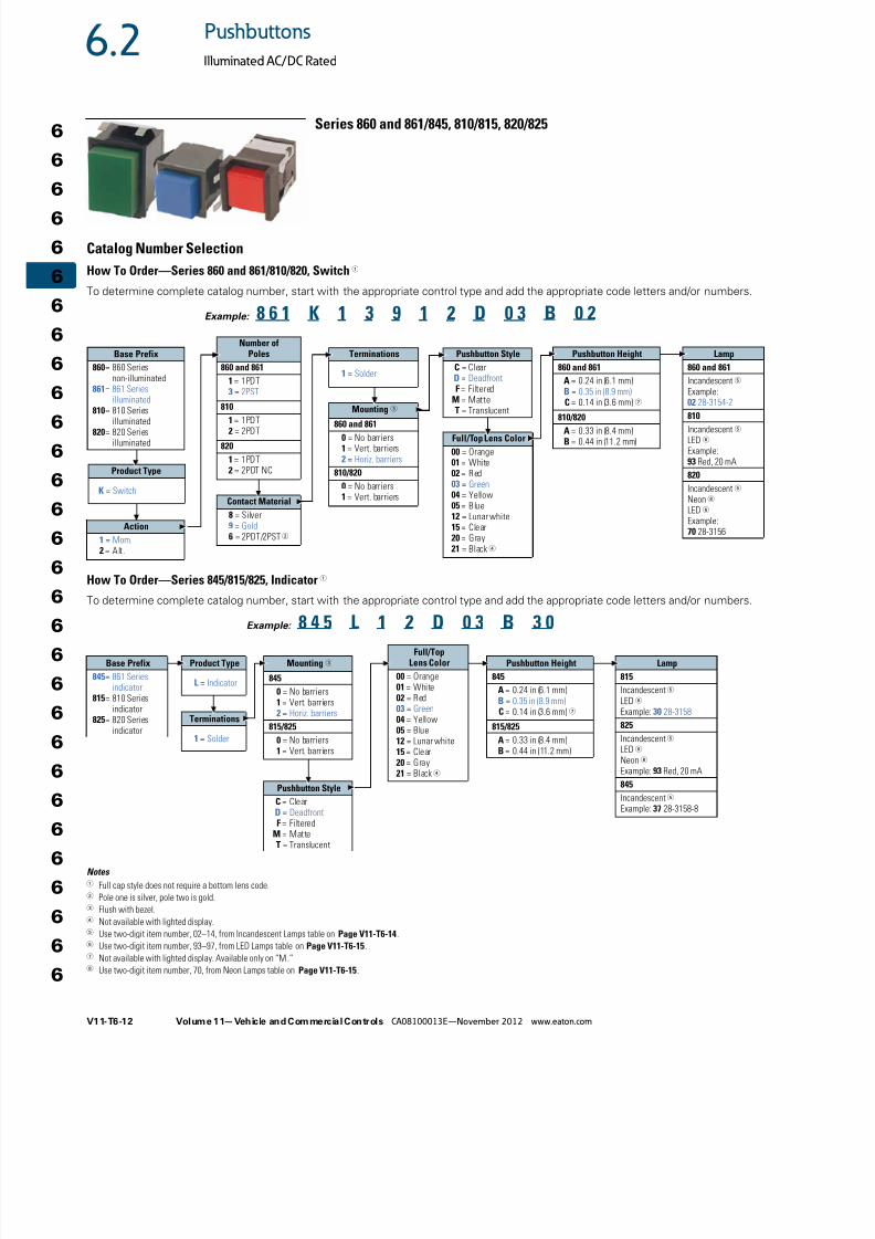
Series 860 and 861/845, 810/815, 820/825
Catalog Number Selection
How To Order—Series 860 and 861/810/820, Switch 1
How To Order—Series 845/815/825, Indicator 1
Notes 1 Full cap style does not require a bottom lens code.2 Pole one is silver, pole two is gold.3 Flush with bezel.4 Not available with lighted display.5 Use two-digit item number, 02–14, from Incandescent Lamps table on Page V11-T6-14.6 Use two-digit item number, 93–97, from LED Lamps table on Page V11-T6-15.7 Not available with lighted display. Available only on “M.”8 Use two-digit item number, 70, from Neon Lamps table on Page V11-T6-15.
To determine complete catalog number, start with the appropriate control type and add the appropriate code letters and/or numbers.
8 6 1 K 1 3 9 1 2 D 0 3 B 0 2
Base Prefix
860= 860 Seriesnon-illuminated
861= 861 Seriesilluminated
810= 810 Seriesilluminated
820= 820 Seriesilluminated
Product Type
K = Switch
Terminations
1 = Solder
Full/Top Lens Color
00 = Orange01 = White02 = Red03 = Green04 = Yellow05 = Blue12 = Lunar white15 = Clear20 = Gray21 = Black4
Pushbutton Height
860 and 861
A = 0.24 in (6.1 mm)B = 0.35 in (8.9 mm)C = 0.14 in (3.6 mm)7
810/820
A = 0.33 in (8.4 mm)B = 0.44 in (11.2 mm)
Lamp
860 and 861
Incandescent5 Example:02 28-3154-2
810
Incandescent5 LED 6 Example:93 Red, 20 mA
820
Incandescent5 Neon8 LED 6 Example:70 28-3156
Example:
Number ofPoles
860 and 861
1 = 1PDT3 = 2PST
8101 = 1PDT2 = 2PDT
820
1 = 1PDT2 = 2PDT NC
Mounting 3860 and 861
0 = No barriers1 = Vert. barriers2 = Horiz. barriers
810/820
0 = No barriers1 = Vert. barriersContact Material
8 = Silver9 = Gold 6 = 2PDT/2PST2
Pushbutton Style
C = ClearD = DeadfrontF = Filtered
M = Matte
T = Translucent
Action
1 = Mom. 2 = Alt.
To determine complete catalog number, start with the appropriate control type and add the appropriate code letters and/or numbers.
8 4 5 L 1 2 D 0 3 B 3 0
Base Prefix
845= 861 Seriesindicator
815= 810 Seriesindicator
825= 820 Seriesindicator
Product Type
L = Indicator
Terminations
1 = Solder
Full/TopLens Color
00 = Orange01 = White02 = Red03 = Green04 = Yellow05 = Blue12 = Lunar white15 = Clear20 = Gray21 = Black4
Example:
Mounting 3
845
0 = No barriers1 = Vert. barriers2 = Horiz. barriers
815/825
0 = No barriers1 = Vert. barriers
Pushbutton Style
C = ClearD = Deadfront
F = FilteredM = MatteT = Translucent
Pushbutton Height
845
A = 0.24 in (6.1 mm)B = 0.35 in (8.9 mm)C = 0.14 in (3.6 mm)7
815/825
A = 0.33 in (8.4 mm)B = 0.44 in (11.2 mm)
Lamp
815
Incandescent5 LED6 Example: 30 28-3158
825
Incandescent5 LED6 Neon8 Example: 93 Red, 20 mA
845
Incandescent5 Example: 37 28-3158-8
8/12/2019 Soft Starters-2
http://slidepdf.com/reader/full/soft-starters-2 13/20
Volume 11—Vehicle and Commercial Controls CA08100013E—November 2012 www.eaton.com V11-T6-13
6.2Pushbuttons
Illuminated AC/DC Rated
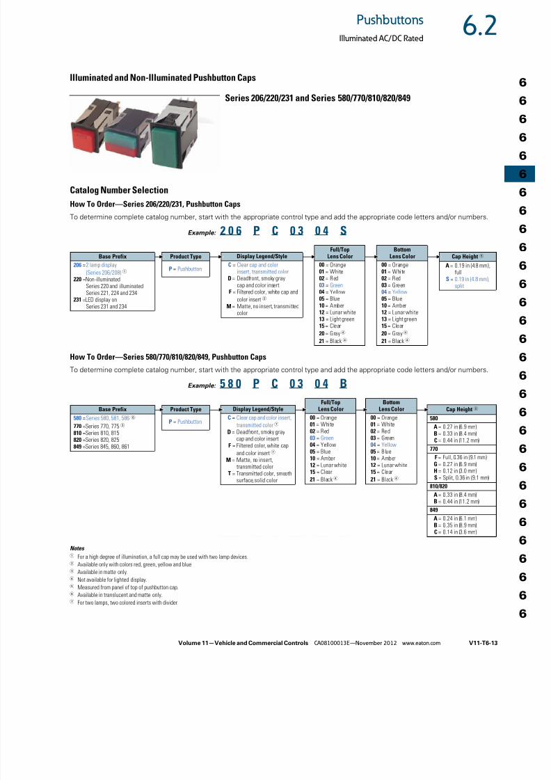
Illuminated and Non-Illuminated Pushbutton Caps
Series 206/220/231 and Series 580/770/810/820/849
Catalog Number Selection
How To Order—Series 206/220/231, Pushbutton Caps
How To Order—Series 580/770/810/820/849, Pushbutton Caps
Notes 1 For a high degree of illumination, a full cap may be used with two lamp devices.2 Available only with colors red, green, yellow and blue.3 Available in matte only.4 Not available for lighted display.5 Measured from panel of top of pushbutton cap.6 Available in translucent and matte only.7 For two lamps, two colored inserts with divider.
To determine complete catalog number, start with the appropriate control type and add the appropriate code letters and/or numbers.
2 0 6 P C 0 3 0 4 S
Base Prefix206 =2 lamp display
(Series 206/208) 1
220 =Non-illuminatedSeries 220 and illuminatedSeries 221, 224 and 234
231 =LED display onSeries 231 and 234
Product Type
P = Pushbutton
Display Legend/StyleC = Clear cap and color
insert, transmitted colorD = Deadfront, smoky gray
cap and color insertF = Filtered color, white cap and
color insert2
M = Matte, no insert, transmittedcolor
Full/Top
Lens Color00 = Orange01 = White02 = Red03 = Green04 = Yellow05 = Blue10 = Amber12 = Lunar white13 = Light green15 = Clear
20 = Gray4
21 = Black4
Cap Height5
A = 0.19 in (4.8 mm),full
S = 0.19 in (4.8 mm),split
Example:
Bottom
Lens Color00 = Orange01 = White02 = Red03 = Green04 = Yellow05 = Blue10 = Amber12 = Lunar white13 = Light green15 = Clear
20 = Gray4
21 = Black4
To determine complete catalog number, start with the appropriate control type and add the appropriate code letters and/or numbers.
5 8 0 P C 0 3 0 4 BBase Prefix
580 =Series 580, 581, 586 6
770 =Series 770, 775 3
810 =Series 810, 815820 =Series 820, 825849 =Series 845, 860, 861
Product Type
P = Pushbutton
Display Legend/Style
C = Clear cap and color insert,
transmitted color7
D = Deadfront, smoky graycap and color insert
F = Filtered color, white cap
and color insert7
M = Matte, no insert,transmitted color
T = Transmitted color, smoothsurface, solid color
Full/TopLens Color
00 = Orange01 = White02 = Red03 = Green04 = Yellow05 = Blue10 = Amber12 = Lunar white15 = Clear
21 = Black4
Cap Height5
580
A = 0.27 in (6.9 mm)B = 0.33 in (8.4 mm)C = 0.44 in (11.2 mm)
770
F = Full, 0.36 in (9.1 mm)G = 0.27 in (6.9 mm)H = 0.12 in (3.0 mm)S = Split, 0.36 in (9.1 mm)
810/820
A = 0.33 in (8.4 mm)B = 0.44 in (11.2 mm)
849
A = 0.24 in (6.1 mm)B = 0.35 in (8.9 mm)C = 0.14 in (3.6 mm)
Example:
BottomLens Color
00 = Orange01 = White02 = Red03 = Green04 = Yellow05 = Blue10 = Amber12 = Lunar white15 = Clear
21 = Black4
8/12/2019 Soft Starters-2
http://slidepdf.com/reader/full/soft-starters-2 14/20
V11-T6-14 Volume 11—Vehicle and Commercial Controls CA08100013E—November 2012 www.eaton.com
6
6
6
6
6
6
6
6
6
6
6
6
6
6
6
6
6
6
6
6
6
6
6
6
6
6
6
6
6
6
6.2 Pushbuttons
Illuminated AC/DC Rated
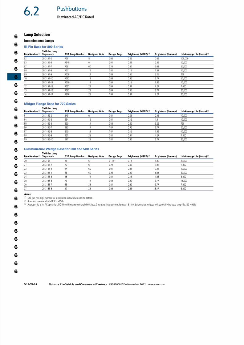
Lamp Selection
Incandescent Lamps
Bi-Pin Base for 800 Series
Midget Flange Base for 770 Series
Subminiature Wedge Base for 200 and 500 Series
Notes 1 Use this two-digit number for installation in switches and indicators.2 Standard tolerance for MSCP is ±25%.3 Average life is for AC operation. DC life will be approximately 50% less. Operating incandescent lamps at 5–10% below rated voltage will generally increase lamp life 200–400%.
Item Number 1To Order LampSeparately ASA Lamp Number Designed Volts Design Amps Brightness (MSCP) 2 Brightness (Lumens) Lab Average Life (Hours)3
02 28-3154-2 7361 5 0.06 0.05 0.63 100,000
03 28-3154-3 7945 6 0.04 0.03 0.38 10,000
07 28-3154-7 7381 6.3 0.20 0.40 5.03 50,000
08 28-3154-8 7371 12 0.04 0.12 1.51 10,000
09 28-3154-9 7330 14 0.08 0.50 6.29 750
10 28-3154-10 7382 14 0.08 0.30 3.77 50,000
11 28-3154-11 7370 18 0.04 0.15 1.89 10,000
12 28-3154-12 7327 28 0.04 0.34 4.27 7,000
13 28-3154-13 7387 28 0.04 0.30 3.77 25,000
14 28-3154-14 7876 28 0.06 0.34 4.27 25,000
Item Number 1To Order LampSeparately ASA Lamp Number Designed Volts Design Amps Brightness (MSCP) 2 Brightness (Lumens) Lab Average Life (Hours)3
51 28-3155-2 345 6 0.04 0.03 0.38 10,000
54 28-3155-5 394 12 0.04 0.12 1.51 10,000
55 28-3155-6 330 14 0.08 0.50 6.29 750
56 28-3155-7 382 14 0.08 0.30 3.77 50,000
57 28-3155-8 370 18 0.04 0.15 1.89 10,000
58 28-3155-9 327 28 0.04 0.34 4.27 7,000
59 28-3155-10 387 28 0.04 0.30 3.77 25,000
Item Number1To Order LampSeparately ASA Lamp Number Designed Volts Design Amps Brightness (MSCP) 2 Brightness (Lumens) Lab Average Life (Hours)3
30 28-3158 56 5 0.115 0.15 1.89 20,000
31 28-3158-2 79 6 0.20 0.60 7.92 1,000
32 28-3158-3 84 6.3 0.04 0.03 0.38 20,000
33 28-3158-4 86 6.3 0.20 0.40 5.03 20,000
34 28-3158-5 18 14 0.04 0.13 1.63 5,000
35 28-3158-6 73 14 0.08 0.30 3.77 15,000
36 28-3158-7 85 28 0.04 0.30 3.77 7,000
37 28-3158-8 17 28 0.06 0.65 8.17 5,000
8/12/2019 Soft Starters-2
http://slidepdf.com/reader/full/soft-starters-2 15/20
Volume 11—Vehicle and Commercial Controls CA08100013E—November 2012 www.eaton.com V11-T6-15
6.2Pushbuttons
Illuminated AC/DC Rated
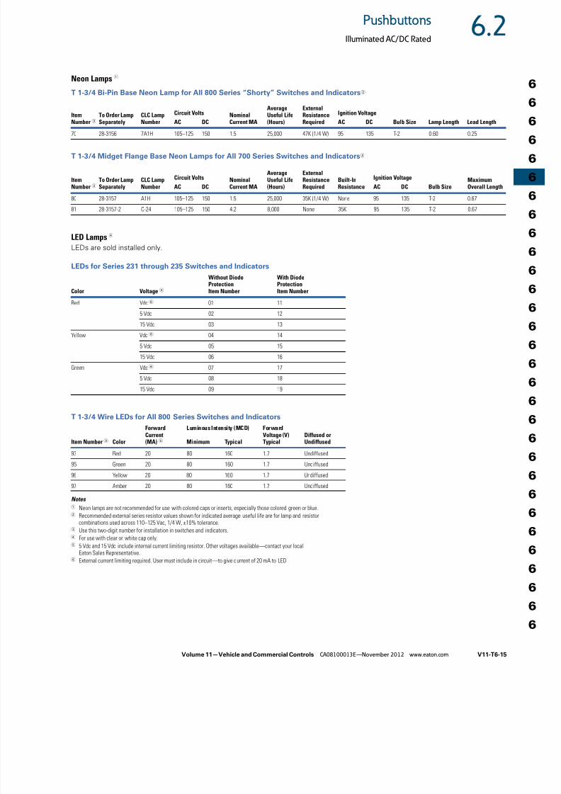
Neon Lamps 1
T 1-3/4 Bi-Pin Base Neon Lamp for All 800 Series “Shorty” Switches and Indicators 2
T 1-3/4 Midget Flange Base Neon Lamps for All 700 Series Switches and Indicators 2
LED Lamps 4
LEDs are sold installed only.
LEDs for Series 231 through 235 Switches and Indicators
T 1-3/4 Wire LEDs for All 800 Series Switches and Indicators
Notes 1 Neon lamps are not recommended for use with colored caps or inserts, especially those colored green or blue.2 Recommended external series resistor values shown for indicated average useful life are for lamp and resistor
combinations used across 110–125 Vac, 1/4 W, ±10% tolerance.3 Use this two-digit number for installation in switches and indicators.4 For use with clear or white cap only.5 5 Vdc and 15 Vdc include internal current limiting resistor. Other voltages available—contact your local
Eaton Sales Representative.6 External current limiting required. User must include in circuit—to give c urrent of 20 mA to LED.
ItemNumber 3
To Order LampSeparately
CLC LampNumber
NominalCurrent MA
AverageUseful Life(Hours)
ExternalResistanceRequired Bulb Size Lamp Length Lead Length
Circuit Volts Ignition Voltage
AC DC AC DC
70 28-3156 7A1H 105–125 150 1.5 25,000 47K (1/4 W) 95 135 T-2 0.60 0.25
ItemNumber 3
To Order LampSeparately
CLC LampNumber
NominalCurrent MA
AverageUseful Life(Hours)
ExternalResistanceRequired
Built-InResistance Bulb Size
MaximumOverall Length
Circuit Volts Ignition Voltage
AC DC AC DC
80 28-3157 A1H 105–125 150 1.5 25,000 35K (1/4 W) None 95 135 T-2 0.67
81 28-3157-2 C-24 105–125 150 4.2 8,000 None 35K 95 135 T-2 0.67
Color Voltage 5
Without DiodeProtectionItem Number
With DiodeProtectionItem Number
Red Vdc 6 01 11
5 Vdc 02 12
15 Vdc 03 13
Yellow Vdc 6 04 14
5 Vdc 05 15
15 Vdc 06 16
Green Vdc 6 07 17
5 Vdc 08 18
15 Vdc 09 19
Item Number 3 Color
ForwardCurrent(MA) 5
Luminous Intensity (MCD) ForwardVoltage (V)Typical
Diffused orUndiffusedMinimum Typical
93 Red 20 80 160 1.7 Undiffused
95 Green 20 80 160 1.7 Undiffused
96 Yellow 20 80 160 1.7 Undiffused
97 Amber 20 80 160 1.7 Undiffused
8/12/2019 Soft Starters-2
http://slidepdf.com/reader/full/soft-starters-2 16/20
V11-T6-16 Volume 11—Vehicle and Commercial Controls CA08100013E—November 2012 www.eaton.com
6
6
6
6
6
6
6
6
6
6
6
6
6
6
6
6
6
6
6
6
6
6
6
6
6
6
6
6
6
6
6.2 Pushbuttons
Illuminated AC/DC Rated
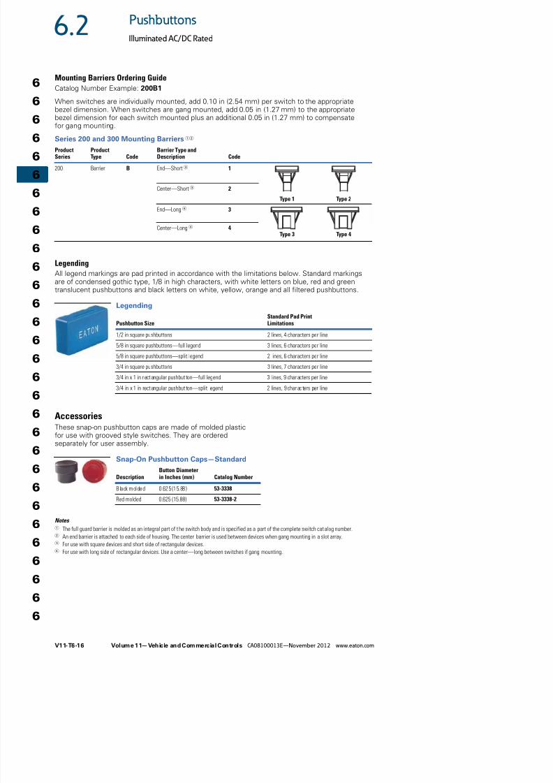
Mounting Barriers Ordering Guide
Catalog Number Example: 200B1
When switches are individually mounted, add 0.10 in (2.54 mm) per switch to the appropriatebezel dimension. When switches are gang mounted, add 0.05 in (1.27 mm) to the appropriatebezel dimension for each switch mounted plus an additional 0.05 in (1.27 mm) to compensatefor gang mounting.
Series 200 and 300 Mounting Barriers 12
LegendingAll legend markings are pad printed in accordance with the limitations below. Standard markingsare of condensed gothic type, 1/8 in high characters, with white letters on blue, red and greentranslucent pushbuttons and black letters on white, yellow, orange and all filtered pushbuttons.
Legending
AccessoriesThese snap-on pushbutton caps are made of molded plasticfor use with grooved style switches. They are orderedseparately for user assembly.
Snap-On Pushbutton Caps—Standard
Notes 1 The full guard barrier is molded as an integral part of the switch body and is specified as a part of the complete switch catalog number.2 An end barrier is attached to each side of housing. The center barrier is used between devices when gang mounting in a slot array.3 For use with square devices and short side of rectangular devices.4 For use with long side of rectangular devices. Use a center—long between switches if gang mounting.
ProductSeries
ProductType Code
Barrier Type andDescription Code
200 Barrier B End—Short3 1
Type 1 Type 2
Center—Short3 2
End—Long4 3
Type 3 Type 4Center—Long 4 4
Pushbutton SizeStandard Pad PrintLimitations
1/2 in square pushbuttons 2 lines, 4 characters per line
5/8 in square pushbuttons—full legend 3 lines, 6 characters per line
5/8 in square pushbuttons—split legend 2 lines, 6 characters per line
3/4 in square pushbuttons 3 lines, 7 characters per line
3/4 in x 1 in rectangular pushbut ton—full legend 3 lines, 9 characters per line
3/4 in x 1 in rectangular pushbut ton—split legend 2 lines, 9 charac ters per line
DescriptionButton Diameterin Inches (mm) Catalog Number
Black molded 0.625 (15.88 ) 53-3338
Red molded 0.625 (15.88) 53-3338-2
8/12/2019 Soft Starters-2
http://slidepdf.com/reader/full/soft-starters-2 17/20
Volume 11—Vehicle and Commercial Controls CA08100013E—November 2012 www.eaton.com V11-T6-17
6.2Pushbuttons
Illuminated AC/DC Rated
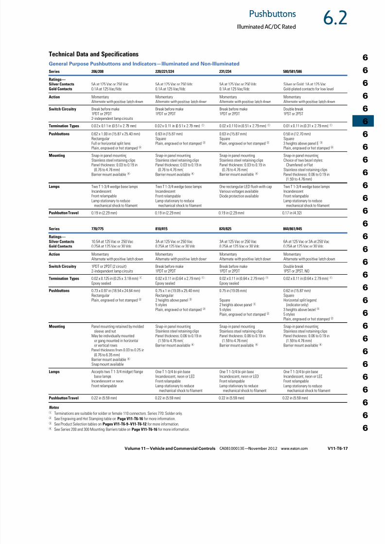
Technical Data and Specifications
General Purpose Pushbuttons and Indicators—Illuminated and Non-Illuminated
Notes 1 Terminations are suitable for solder or female 110 connectors. Series 770: Solder only.2 See Engraving and Hot Stamping table on Page V11-T6-16 for more information.3 See Product Selection tables on Pages V11-T6-9–V11-T6-12 for more information.4 See Series 200 and 300 Mounting Barriers table on Page V11-T6-16 for more information.
Series 206/208 220/221/224 231/234 580/581/586
Ratings—Silver Contacts
Gold Contacts
5A at 125 Vac or 250 Vac
0.1A at 125 Vac/Vdc
5A at 125 Vac or 250 Vdc
0.1A at 125 Vac/Vdc
5A at 125 Vac or 250 Vdc
0.1A at 125 Vac/Vdc
Silver or Gold: 1A at 125 Vac
Gold-plated contacts for low levelAction Momentary
Alternate with positive latch downMomentaryAlternate with positive latch down
MomentaryAlternate with positive latch down
MomentaryAlternate with positive latch down
Switch Circuitry Break before make1PDT or 2PDT2-independent lamp circuits
Break before make1PDT or 2PDT
Break before make1PDT or 2PDT
Double break1PST or 2PST
Termination Types 0.02 x 0.11 in (0 .51 x 2.79 mm) 0.02 x 0.11 in (0 .51 x 2.79 mm)1 0.02 x 0.110 in (0.51 x 2.79 mm)1 0.01 x 0.11 in (0.31 x 2.79 mm)1
Pushbuttons 0.62 x 1.00 in (15.87 x 25.40 mm)RectangularFull or horizontal split lensPlain, engraved or hot stamped 2
0.63 in (15.87 mm)SquarePlain, engraved or hot stamped 2
0.63 in (15.87 mm)SquarePlain, engraved or hot stamped 2
0.50 in (12.70 mm)Square3 heights above panel E 3
Plain, engraved or hot stamped 2
Mounting Snap-in panel mountingStainless steel retaining clipsPanel thickness: 0.03 to 0.19 in
(0.76 to 4.76 mm)Barrier mount available 4
Snap-in panel mountingStainless steel retaining clipsPanel thickness: 0.03 to 0.19 in
(0.76 to 4.76 mm)Barrier mount available 4
Snap-in panel mountingStainless steel retaining clipsPanel thickness: 0.03 to 0.19 in
(0.76 to 4.76 mm)Barrier mount available 4
Snap-in panel mountingChoice of two bezel styles: Chamfered or FlatStainless steel retaining clipsPanel thickness: 0.06 to 0.19 in
(1.59 to 4.76 mm)Lamps Two T 1-3/4 wedge base lamps
IncandescentFront relampableLamp stationary to reduce
mechanical shock to filament
Two T 1-3/4 wedge base lampsIncandescentFront relampableLamp stationary to reduce
mechanical shock to filament
One rectangular LED flush with capVarious voltages availableDiode protection available
Two T 1-3/4 wedge base lampsIncandescentFront relampableLamp stationary to reduce
mechanical shock to filament
Pushbutton Travel 0.19 in (2.29 mm) 0.19 in (2.29 mm) 0.19 in (2.29 mm) 0.17 in (4.32)
Series 770/775 810/815 820/825 860/861/845
Ratings—Silver ContactsGold Contacts
10.5A at 125 Vac or 250 Vac0.25A at 125 Vac or 30 Vdc
3A at 125 Vac or 250 Vac0.25A at 125 Vac or 30 Vdc
3A at 125 Vac or 250 Vac0.25A at 125 Vac or 30 Vdc
6A at 125 Vac or 3A at 250 Vac0.25A at 125 Vac or 30 Vdc
Action MomentaryAlternate with positive latch down
MomentaryAlternate with positive latch down
MomentaryAlternate with positive latch down
MomentaryAlternate with positive latch down
Switch Circuitry 1PDT or 2PDT (2 circuit)
2-independent lamp circuits
Break before make
1PDT or 2PDT
Break before make
1PDT or 2PDT
Double break
1PST or 2PST, NO
Termination Types 0.02 x 0.125 in (0.25 x 3.18 mm)1
Epoxy sealed0.02 x 0.11 in (0.64 x 2.79 mm) 1
Epoxy sealed0.02 x 0.11 in (0.64 x 2.79 mm)1
Epoxy sealed0.02 x 0.11 in (0.64 x 2.79 mm)1
Pushbuttons 0.73 x 0.97 in (18.54 x 24.64 mm)RectangularPlain, engraved or hot stamped 2
0.75 x 1 in (19.05 x 25.40 mm)Rectangular2 heights above panel 3
5 stylesPlain, engraved or hot stamped 2
0.75 in (19.05 mm)
Square2 heights above panel 3
5 stylesPlain, engraved or hot stamped 2
0.62 in (15.87 mm)SquareHorizontal split legend
(indicator only)3 heights above bezel 3
5 stylesPlain, engraved or hot stamped 2
Mounting Panel mounting retained by molded sleeve and nut
May be individually mountedor gang mounted in horizontalor vertical rows
Panel thickness from 0.03 to 0.25 in(0.76 to 6.35 mm)
Barrier mount available
4
Snap mount available
Snap-in panel mountingStainless steel retaining clipsPanel thickness: 0.06 to 0.19 in
(1.59 to 4.76 mm)Barrier mount available 4
Snap-in panel mountingStainless steel retaining clipsPanel thickness: 0.06 to 0.19 in
(1.59 to 4.76 mm)Barrier mount available 4
Snap-in panel mountingStainless steel retaining clipsPanel thickness: 0.06 to 0.19 in
(1.59 to 4.76 mm)Barrier mount available 4
Lamps Accepts two T 1-3/4 midget flange base lamps
Incandescent or neonFront relampable
One T 1-3/4 bi-pin baseIncandescent, neon or LEDFront relampableLamp stationary to reduce
mechanical shock to filament
One T 1-3/4 bi-pin baseIncandescent, neon or LEDFront relampableLamp stationary to reduce
mechanical shock to filament
One T 1-3/4 bi-pin baseIncandescent, neon or LEDFront relampableLamp stationary to reduce
mechanical shock to filament
Pushbutton Travel 0.22 in (5.59 mm) 0.22 in (5.59 mm) 0.22 in (5.59 mm) 0.22 in (5.59 mm)

8/12/2019 Soft Starters-2
http://slidepdf.com/reader/full/soft-starters-2 18/20
V11-T6-18 Volume 11—Vehicle and Commercial Controls CA08100013E—November 2012 www.eaton.com
6
6
6
6
6
6
6
6
6
6
6
6
6
6
6
6
6
6
6
6
6
6
6
6
6
6
6
6
6
6
6.2 Pushbuttons
Illuminated AC/DC Rated
Terminal IdentificationWhen specified on order,switches will have the terminalsidentified as shown in theillustration at right. Terminalmarkings will be ink-stamped on
the side of the switch case andunused terminal positions willnot be identified.
All views are rear of switch withkeyway or at down as applicable.Terminal numbers 2, 2 and 5 and5 and 8 are considered inboardterminals for single-, two- andfour-pole switches respectively.All others are consideredoutboard.
Circuit DiagramsPushbutton Circuit Diagrams
LegendsPushbutton Legend
Notes 1 Poles 11 and 12 may be eliminated for three-pole devices.2 Poles 10, 11 and 12 may be eliminated for three-pole devices.3 Dependent lamp.4 Independent lamp.5 Two circuit—indicates a special type of double-throw switch in which the two circuits being
controlled may be independent of each other.6 For 206 Series, an additional lamp is available.7 Available in 1PDT or 2PDT.
Circuit Letter Schematic Circuit Letter SchematicA1PST
I2 circuit5
B1PDT
J1PST
C2PST
K1PDT
D2PDT
L2PST
E4PST1
M2PST
F4PDT2
N6
2PDT
G 3
1PSTP1PDT
H 4
1PDTQ7
2 circuit
1
2
3
1
2
3
4
5
6
1
2
3
4
5
6
7
8
9
10
11
12
Single-Pole
Two-Pole
Four-Pole
3
2
3 6
1 4
2
3
1
3
2
6
5
2
3
1
5
6
4 4
31
2
3
2
6
5
9
8
12
11
1 3
2 4
2
3
1
5
6
4
8
9
7
11
12
10
3
2
4
6
3
2
4
6
BA
C
C
NCNO
GH
NONC
Legend Rocker Switch Type
Contact terminal—will make contact with switch lever
Isolated terminal—does not make contact with lever
Center terminal and switch lever
Bulb
Momentary contact
Denotes mechanical contact portion

8/12/2019 Soft Starters-2
http://slidepdf.com/reader/full/soft-starters-2 19/20
Volume 11—Vehicle and Commercial Controls CA08100013E—November 2012 www.eaton.com V11-T6-19
6.2Pushbuttons
Illuminated AC/DC Rated
DimensionsApproximate Dimensions in Inches (mm)
206 Series
220 Series
231 Series
580 Series
770 Series
810 Series
LEGEND
LEGEND
NCNC
NO NO
C A
B
2C
0.312
(7.92)
0.400(11.18)
1.133(28.78)
0.900(22.86)
0.740(18.80)
0.190
(4.83)
1.200(30.48)
0.990(25.15)
0.600(15.24)
0.800(20.32)
1.400(35.56)
0.705 + 0.005(19.05 + 0.127/ – 0.000)
1.140 + 0.005(28.96 + 0.127/ – 0.000)
LEGEND
NCNC
NO NO
C
0.312(7.92)
0.400(10.16)
0.500
(12.70)
0.740(18.80)
Typ.
0.190(4.83)
0.800(20.32)
Typ.0.600
(15.24)Typ.
1.400(35.56)
C
0.750 + 0.005(19.05 + 0.127/ – 0.000)
0.750 + 0.005(19.05 + 0.127/ – 0.000)
NCNC
NO NO
C
0.312(7.92)
0.400
(10.16)
0.500(12.70)
0.740(18.80)
Typ.
0.190(4.83)
0.800(20.32)
Typ.
0.600(15.24)
Typ.
1.400(35.56)
C
0.100(2.54)
CL 0.300(7.62)
0.140(3.56)
LED
CL
0.750 + 0.005(19.05 + 0.127/ – 0.000)
0.750 + 0.005(19.05 + 0.127/ – 0.000)
0.400(10.16)
0.310
(7.87)
0.890(22.61)
A = 0.270 (6.86)B = 0.330 (8.38)
C = 0.440 (11.18)
0.685(17.40)Typ.
0.500(12.70)
Typ.
L E G E N D
0.010 (0.254)Rad. Max.
0.625 + 0.010(15.88 + 0.254/ – 0.000)
0.625 ± 0.010(15.88 ± 0.254)
0.400(10.16)
0.960(24.38)
0.970(24.64)
1.190(30.23)
0.730(18.54)
F-S = 0.360 (9.14)G = 0.270 (6.86)H = 0.120 (3.05)
0.120(3.05)
Panel thickness0.030 (0.762) to
0.250 (6.35)
2.200(55.88)
0.125(3.18)
0.875 ± 0.005(22.23 ± 0.127)
1.110 ± 0.005(28.19 ± 0.127)
0.550(13.97)
0.940(23.88)
0.310
(7.87)
0.910(23.11)
A = 0.330 (8.38)
B = 0.440 (11.18)
1.000(25.40)
LEGEND
0.010 (0.254)Rad. Max.
1.170(29.72)
0.750(19.05)
1.070(27.18)
1.110 ± 0.005(28.19 ± 0.127)
0.875 ± 0.005(22.23 ± 0.127)

8/12/2019 Soft Starters-2
http://slidepdf.com/reader/full/soft-starters-2 20/20
6
6
6
6
6
6
6
6
6
6
6
6
6
6
6
6
6
6
6
6
6
6
6
6
6
6
6
6
6
6
6.2 Pushbuttons
Illuminated AC/DC Rated
Approximate Dimensions in Inches (mm)
820 Series 860 Series
A = 0.330 (8.38)B = 0.440 (11.18)
LEGEND
0.750(19.05)
Typ.
0.940(23.88)
Typ.
0.025(0.64)
0.280 (7.11)
0.840(21.34)
0.660(16.76)
1.110 (28.19)
0.160(4.06)
0.160 (4.06)
0.310(7.87)
0.910(23.11) 0.090
(2.29)
0.010 (0.254)Rad. Max.
0.875 + 0.005(22.23 + 0.127/ – 0.000)0.875 + 0.005
(22.23 + 0.127/ – 0.000)
LEGEND
0.755 ± 0.005(19.18 ± 0.127)
0.755 ± 0.005(19.18 ± 0.127)
0.010 (0.254)Rad. Max.
0.280(7.11)
0.515(13.08)
0.250(6.35)
1.000(2.54)0.310
(7.87)
0.620(15.75)Typ.
0.850(21.59)Typ.
A = 0.240 (6.10)B = 0.350 (8.89)C = 0.140 (3.56)