soft tissue cutting aspiration device and method
TRANSCRIPT

_ US005102410A
UHlted States Patent [19] [11] Patent Number: 5,102,410 Dressel [45] Date of Patent: Apr. 7, 1992
[54] SOFT TISSUE CUTTING ASPIRATION 4,857,063 8/1989 Glenn ................................ .. 604/317 DEVICE AND METHOD 4,863,439 9/1989 Sanderson 604/264
4,886.491 12/1989 Parisi et a1. .. .... .. 604/22
[76] Inventor: Thomas D. Dressel, 8725 Walton 4,955,882 9/1990 l-lakky ................................. .. 606/14 Oaks Cir., Bloomington, Minn. 55438
FOREIGN PATENT DOCUMENTS l. .: ,6 [2]] App No 577 79 3209444 10/1982 Fed. Rep. ofGermany ...... .. 606/14
[22] Flled: Oct. 9’ 1990 Primary Examiner-Max Hindenburg Related us. Application Data Attorney, Agent, or F1rm-Faegre & Benson
[63] Continuation-impart of Ser. No. 485,081, Feb. 26, 1990, [57] ABSTRACT Pal- NO- 4'9351027- A laser soft tissue aspiration device comprises an aspira
[51] Int. Cl.5 ............................................ .. A618 17/ 36 tion cannula housing a laser energy transmitting’ means [52] US. Cl. .................................... .. 606/15; 606/17 f°r “mducting laser energy to the Site Within a patiem‘s [58] Field of Search .............................. .. 128/395-398, body for aspiration of Soft Iissue- The cannula is 1219
128/749’ 752; 606/3’ 1346, 45, 46, 49, 17 vided with an aspiration inlet port adjacent the cannula _ distal end. The proximal end of the cannula is provided
[56] References C'ted , with ?uid ?ow connection to an aspiration source. A
US. PATENT DOCUMENTS laser guide tube is additionally provided housing the 3,858.577 1/1975 Bass et a1. . .................. .. 606/15 laser energy transmitting means exm‘ding kmgimdi' 4,169,984 10/1979 Parisi ........ .. 128/24 A Bally Within the cannula lumen from a laser energy 4,266,547 5/1931 Komiya , _ , _ , _ . , , _ _ _ _ _ ,_ 123/395 source at the cannula proximal end and terminating at a
4,492,230 1/1985 Sunago et a1. . 606/13 point immediately prior to the aspiration inlet port. The 415159533 5/ 1935 5012611 -------------- - 604/22 tube also provides a conduit for transmitting cooling 453L934 7/1985 xf’ssovsky 3‘ a1‘ ------ " 604/22 and cleaning ?uid ?ow for the laser energy transmitting 4,608,980 9/1986 Aihara .............. .. 128/3031 means
4,633,872 1/1987 ChatTee et al. . 128/303.l ‘ 4,641,912 2/1987 Goldenberg . . . . . . . . . . . . . . . .. 128/6 A surgical method of aspirating soft tissue from a pa
4.646.734 3/1987 Cabrera et a1- -- 128/ 303-1 tient in vivo using this device is also provided transmit’ 4,676,242 6/1987 D01 ............... ..
.i ..... .. 604/22 1313:: 2mm 604/119 through the aspiration inlet port and the cannula by 4’784’649 11/1988 1323? """""""""" " 604/240 means of an aspiration source at the proximal end of the
4,792.327 12/1988 Swartz ......... .. cannula
4,799,754 1/1989 Godenberg 4,834,703 5/1989 Dubrul et al. ...................... .. 604/48 9 Claims, 11 Drawing Sheets
m“
‘- 128/3031 ting means. Separated soft tissue and ?uid is aspirated”


US. Patent Apr. 7, 1992 Sheet 2 of 11 I ' 5,102,410
////m///% mm vm mm on /////////////////// ////JW/// m_ 21k ow [mm N
N N_

US. Patent Apr. 7, 1992 Sheet 3 of 11 ‘ 5,102,410
M l
30
ig. 4

US. Patent Apr. 7, 1992 Sheet 4 of 11 5,102,410
wm4/ Z.NA/////4.W////?////w/////¢////Qv / r V f V I r f 1/
m .ME

US. Patent Apr. 7, 1992 Sheet 5 of 11 5,102,410
u///////////////////~ W L _////,////////)//////¢ #0
OK Q .i
/ L///////////////////V\ .. Q
@ 7//////////////////V% % 8p Twig VQM TQM w “a:

US. Patent Apr. 7, 1992 Sheet 6 of 11 5,102,410

US. Patent Apr. 7, 1992 Sheet 7 of 11 5,102,410

US. Patent Apr. 7, 1992 Sheet 8 of 11 5,102,410
. x mm“ m! at
\R: \ wt
I? I v I I f I Y I I I Y I I I Y I I I A f A I J I V I I J A I I V I I I I I I I I A I I I v ¢~
f / NH .ME w: wt
, m2 m8 , .
cw“ . v2 WQV wk“ mvJ\o§§k
, ....l. 93
A NN / wt w?/ @ v: w: o: m:
US. Patent I Apr. 7, 1992 Sheet 9 of 11 -
\ L x A x
w ‘
............-.______ _\ \
5,102,410

US. Patent Apr. 7, 1992 Sheet 10 of 11 5,102,410
WNW
/
I I \éékkmwmmw
“KN

US. Patent Apr. 7, 1992 Sheet 11 of 11 5,102,410
// /m/////v/ ///A 2%

5,102,410 1
SOFT TISSUE CUTTING ASPIRATION DEVICE AND METHOD
RELATED U.S. APPLICATION DATA
This application is a continuation-in-part of U.S. Ser. No. 07/485,081, ?led Feb. 26, 1990, entitled SOFT TISSUE ASPIRATION DEVICE AND METHOD, now U.S. Pat. No. 4,985,027..
FIELD OF THE INVENTION
This invention relates to a device and method for improving the surgical procedure of soft tissue removal by aspiration and more particularly to a device and method utilizing laser energy to more readily and safely facilitate the separating of soft tissue from a patient in vivo. This invention has immediate and direct applica tion to the surgical procedure of liposuction or body contouring as well as application in the surgical proce dures of other soft tissue removal such as brain tissue, eye tissue, and other soft tissue inaccessible to other soft tissue aspiration techniques.
BACKGROUND OF THE INVENTION I
Within the past decade, the surgical use of lasers to cut, cauterize and ablate tissue has been developing rapidly. Advantages to the surgical use of laser energy lie in increased precision and maneuverability over conventional techniques. Additional bene?ts include prompt healing with less post-operative pain, bruising, and swelling. Lasers have become increasingly impor tant, especially in the ?elds of Ophthalmology, Gyne cology and Dermatology, as a less invasive, more effec tive surgical therapeutic modality which allows the reduction of the cost of procedures and patient recov ery times due to diminished tissue trauma, bleeding, swelling and pain. The C0; laser has achieved wide spread use in surgery for cutting and vaporizing soft tissue. The C0; laser energy has a very short depth of penetration, however, and does not effectively cauter~ ize small blood vessels. Other means such as electrocau tery must be used to control and minimize blood loss. The Neodymium-YAG laser, on the other hand, be cause of its greater depth of tissue penetration, is very effective in vaporizing soft tissue and cauterizing small blood vessels. But as a result of this great depth of tissue penetration, the Neodymium-YAG laser has achieved limited use in the ?eld of soft tissue surgery because of the possibility of unwanted damage to deeper tissues in the path of the laser energy beam.
Liposuction, a surgical technique of removing un wanted fat deposits for the purpose of body contouring, has achieved widespread use. In the U.S., over 100,000 liposuction procedures were performed in 1989 alone. This technique utilizes a hollow tube or cannula with a blunt tip and a side hole or tissue aspiration inlet port near its distal end. The proximal end of the cannula has a handle and a tissue outlet port connected to a vacuum aspiration pump. In use, a small incision is made, the cannula tip and adjacent tissue inlet port is passed be neath the surface of the skin into the unwanted fat de posit. The vacuum pump is then activated drawing a small amount of tissue into the lumen of the cannula via the inlet port. Longitudinal motion of the cannula then removes the unwanted fat by a combination of sucking and ripping actions. This ripping action causes exces sive trauma to the fatty tissues resulting in considerable blood loss and postoperative bruising, swelling and
5
25
30
35
45
50
55
65
2 pain. Proposed advances in the techniques and appara tus in this ?eld have been primarily directed to the design of the aspiration cannula, and more recently have involved the application of ultrasound and irriga tion to melt and solubilize fatty tissue or the use of an auger, within the lumen of the cannula, to facilitate soft tissue removal. These proposed advances do not ade quately address the goals of the surgical procedure: the efficient and precise removal of soft tissue with minimal tissue trauma and blood loss.
This invention utilizes a modi?cation of a suction lipectomy cannula, already in clinical use, to position soft tissue within a protective chamber, allowing a Neodymium-YAG laser energy beam to cut and cauter ize the soft tissue without fear of unwanted damage to surrounding or deeper tissues. This invention renders the removal of soft tissue safer, more precise, faster (and thus more ef?cient) and minimizes tissue trauma by eliminating the ripping action inherent in the conven tional liposuction method.
This invention, by eliminating the ripping action of the conventional liposuction method, expands the scope of soft tissue removal. Currently, the liposuction method is limited to the aspiration of fat. Other soft tissues, such as breast tissue, lymphangiomas, and hem angiomas are too dense or too vascular to allow effi cient and safe removal utilizing the liposuction method. This invention with the precise cutting and coagulating action of the Neodymium-YAG laser or other ?ber delivered cautery and coagulating laser, within the cannula, Permits the removal of these dense or vascular soft tissues.
This invention, by controlling the depth of penetra-u tion of the Neodymium-YAG laser within the protec tive aspiration cannula, expands the surgical applicabil ity of the Neodymium-YAG laser and other lasers. This laser can now be used, for example, in the precise re moval of brain tissue without fear of unwanted damage to surrounding or deeper tissues. At this time, the C0; laser is extensively used for the vaporization of brain tumors, but because of its inability to effectively coagu late blood vessels, other methods such as electrocautery must be used to control blood loss during the proce dure. In addition, because the vaporization of tissue generates large volumes of noxious and potentially toxic smoke, expensive, noisy and cumbersome suction de vices must be used to eliminate the smoke from the surgical ?eld. This invention, by utilizing the more effective coagulating power of the Neodymium-YAG laser, within the aspiration cannula, permits the com bined action of tissue cutting, control of blood loss, and elimination of smoke from the surgical ?eld. The basic design of the present Soft Tissue Laser
Aspiration Device of this invention can be scaled down to permit soft tissue aspiration in other parts of the body. For example, an appropriately sized version of the present device can be used for safe removal of scar tissue from within the eye or adjacent to the retina and lens tissue from within the eye. Other appropriately sized and scaled versions of the present device may also _ be used for the removal of other unwanted soft tissues within the body. For example: removal of unwanted tracheal tissue, such as bronchial adenomas; removal of polyps and other soft tissue from within the lumen of the gastrointestinal tract; for endometrial ablations within the uterus; in conjunction with laparoscopic

5,102,410 3
techniques to remove endometrial tissue within the abdomen.
BRIEF DESCRIPTION OF THE INVENTION
This invention provides a soft tissue aspiration device comprising an aspiration cannula and a ?uid and laser ?ber guide tube extending longitudinally. The guide tube housing a laser energy transmitting ?ber for con ducting the laser energy to the soft tissue removal site within the patient’s body and also housing a ?uid ?ow path around the laser energy transmitting ?ber. The aspiration cannula has a proximal and a distal end. The cannula is provided with a soft tissue aspiration inlet port adjacent to the cannula distal end. The proximal end of the cannula is attached to a handle which is provided with a ?uid ?ow delivery port, a laser energy transmitting ?ber inlet port, and an aspirated soft tissue outlet port. The ?uid and laser ?ber guide tube extends longitudinally from near the proximal end of the soft tissue aspiration device to a point immediately prior to the soft tissue aspiration inlet port within the cannula. A laser energy transmitting ?ber extends from a laser energy source to the proximal end of the handle and longitudinally within the guide tube to a point immedi ately prior to the terminal point of the guide tube. Within the soft tissue aspiration device guide tube, the laser energy transmitting ?ber is surrounded by ?uid ?ow from a ?uid source to the laser guide tube terminal point.
5
20
25
This invention also provides a surgical method of 30 aspirating soft tissue from a patient in vivo using the device just described.
BRIEF DESCRIPTION OF THE DRAWINGS
FIG. 1 is a side cut-away elevation view of a ?rst soft tissue aspiration device of the present invention; FIG. 2 is an exploded longitudinal section view of the
distal end of the cannula of the device of FIG. 1; FIG. 3 is an exploded view similar to FIG. 2, show
ing the distal end of the laser ?ber optic delivery system adjacent the soft tissue aspiration inlet port; FIG. 4 is a partial exploded longitudinal section view
of the handle and proximal end cap of the ?rst device showing the attachments of the ?uid and laser guide tube to the laser ?ber and sources of ?uid; FIG. 5 is a partial exploded longitudinal section
through the handle of the ?rst device showing the ?uid and laser ?ber guide tube, Te?on coaxial ?uid delivery tube and channel, and laser ?ber;
FIG. 6 is a partial exploded longitudinal section of the ?rst laser ?ber optic delivery system with Te?on coax ial ?uid delivery tube; FIG. 7 is a side cut-away elevation view of the ?rst
soft tissue aspiration device showing the optional ?uid delivery port and bushing for use with alternative ?ber optic delivery system; FIG. 8 is a partial exploded longitudinal section view
of the handle and proximal end cap of the ?rst device showing the attachments of the ?uid and laser guide tube to the alternative ?ber optic delivery system and source of ?uid; FIG. 9 is a partial exploded longitudinal section of an
alternative laser ?ber optic delivery system without Te?on coaxial ?uid delivery tube; FIG. 10 is a cut-away detail of the ?rst laser soft
tissue device illustrated in position for performing lipo suction within a fatty deposit of a body intermediate overlying epidermal layer and underlying muscle layer;
35
45
65
4 FIG. 11 is a side cut-away elevation view of a side
cutting neurological soft tissue aspiration embodiment of the present invention; FIG. 12 is a partial exploded longitudinal section
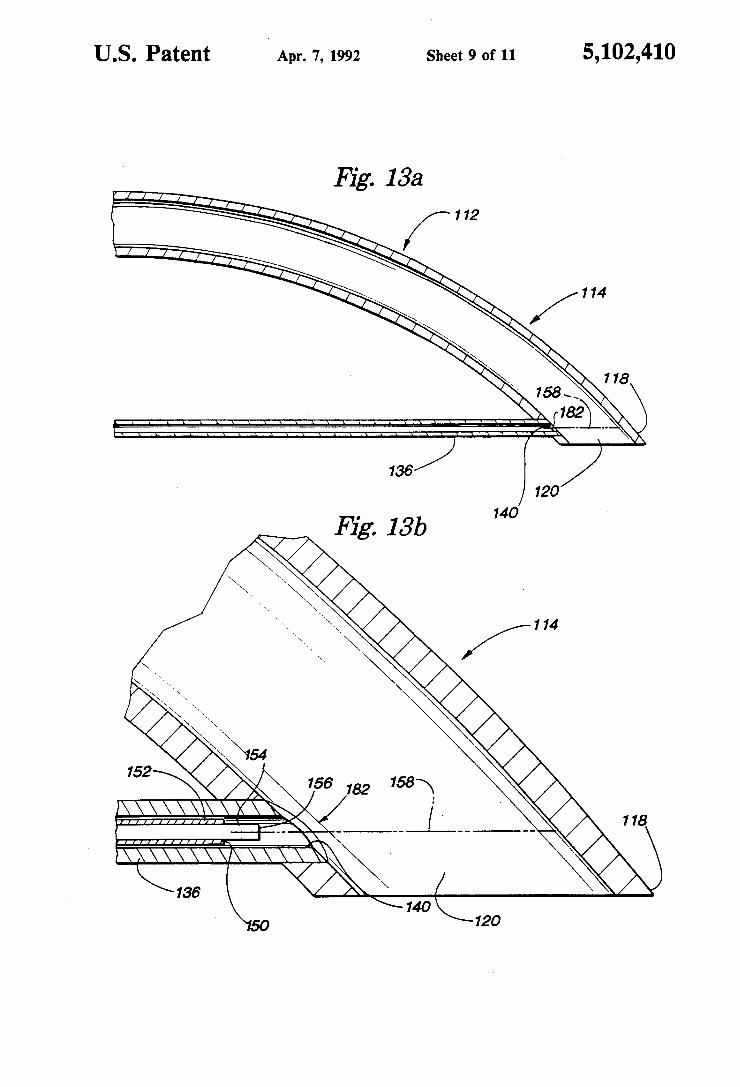
view of the handle of the device of FIG. 11 showing the ?uid and laser ?ber guide tube and the ?uid and laser energy source port; FIGS. 13(0) and 13(b) are partial exploded longitudi
nal section view of the distal end of the cannula of the device of FIG. 11; FIG. 14 is a side cut-away elevation view of an end
cutting neurological soft tissue aspiration embodiment of the present invention; FIG. 15 is a partial exploded longitudinal section
view of the handle of the device of FIG. 14 showing the ?uid and laser ?ber guide tube and energy source port; and FIG. 16 is a partial exploded longitudinal section
view of the distal end of the cannula of the device of FIG. 14 showing the laser ?ber guide tube and re?ect ing means.
DETAILED DESCRIPTION OF THE INVENTION
A. The First Soft Tissue Aspiration Device; FIGS. 1-10
FIGS. 1, 7 and 10 illustrate a ?rst laser soft tissue device 10 according to the present invention. The de vice 10 includes an aspiration cannula 12 having soft tissue inlet port 20 adjacent to the distal end 14 and cannula tip 18. As illustrated in FIGS. 1, 2 and 7, the cannula tip 18 can advantageously be a generally rounded, blunt or bullet shaped tip attached to the can nula 12 by welding or soldering. As illustrated in FIGS. 1 and 7, the cannula proximal end 16 is retained within the distal handle end cap 24, the aspirated soft tissue outlet port 28 is retained within the proximal handle end cap 26, and the distal handle end cap 24 and proximal handle end cap 26 are retained within the handle 22. The soft tissue outlet port is connected to an aspiration source by a plastic tubing (not shown). As illustrated in FIGS. 1, 2, 3, 4, 5 and 7, a ?uid and
laser ?ber guide tube extends longitudinally within the ?rst soft tissue aspiration device from the proximal handle end cap 26, at the laser energy source port 41, terminating at a point 40 immediately proximal to the soft tissue aspiration inlet port 20. The ?uid and laser ?ber guide tube consists of the coaxial ?uid channel 30 drilled in the proximal handle end cap 26, the ?uid and laser ?ber large guide tube 32, the guide tube transition coupler 34, and the ?uid and laser ?ber small guide tube 36. The large guide tube 32 is of suf?cient internal diam eter (about 0.094") to accommodate the Te?on coaxial ?uid delivery tube 44 (FIGS. 4, 5 and 6). The small guide tube is of suf?cient internal diameter (about 0.054") to accommodate the Te?on laser ?ber sheath 50 and laser ?ber 54 and to provide clearance for the coax ial ?uid channel 38 (FIGS. 3, 4 and 5). The guide tube transition coupler 34 is positioned within the handle 22 proximal to the proximal end of the cannula l6 and is drilled to accommodate the external diameters of the large 32 and small guide tubes 36. The guide tube com ponents are joined together and to the proximal handle end cap 26 and within the aspiration cannula inner wall utilizing a means such as soldering or welding. The ?uid and laser guide tube is provided with an O-ring seal 46 at its retention within the proximal handle end cap 26 at the laser energy source port 41.

5,102,410 5
Housed within the ?uid and laser ?ber guide tube is the laser ?ber optic delivery system 62, shown in FIGS. 1, 2, 3, 4, 5 and 6, and consists of the Te?on coaxial ?uid delivery tube 44, the Te?on laser ?ber sheath 50, and the laser ?ber 54, having laser discharge axis 58. The Te?on coaxial ?uid delivery tube 44 is connected to a saline ?uid source and pump integral with the laser energy source (not shown) and passes into the proximal end cap of the handle 16, through the ?uid and laser guide channel 30 into the large guide tube 32, terminat ing at a point 48 within the large guide tube. The large guide tube 32 is maintained in position within cannula 12, for example, by silver solder through holes 37, as illustrated in FIGS. 2 and 3. The Te?on coaxial ?uid delivery tube delivers cooling and irrigating ?uid into the ?uid and laser large guide tube 32, the ?uid passes distally within the guide tube 32 surrounding the Te?on laser ?ber sheath 50 and laser ?ber 54 to the terminal point of the small guide tube 36. The laser ?ber 54 con stitutes the laser energy transmitting means, extending from the laser energy source (not shown), through the energy source port 41 to a terminal point 56 immedi ately prior to the terminal point of the ?uid and laser ?ber guide tube 40. The retention of the laser ?ber optic system 62 is accomplished by a retaining screw 42 at the ?uid and laser energy source port 41. FIGS. 7, 8 and 9 illustrate minor modi?cations of the
preferred con?guration of the present invention which allow the soft tissue aspiration cannula to accommodate an alternative ?ber optic delivery system 64 (FIG. 9) which does not incorporate a Te?on coaxial ?uid deliv ery tube. A bushing 68 is positioned within the ?uid and laser guide channel 30 to allow a ?uid and air-tight seal at the ?uid and energy source port 41. An optional ?uid delivery port 66 is provided to allow the passage of cooling and irrigating ?uid from a ?uid source and pump (not shown). This port 66 is ?tted with a ?uid and air tight plug 60 when the Te?on coaxial ?uid delivery tube is used. As will be apparent to those skilled in this art, a
shorter and thinner soft tissue aspiration cannula 12 will be useful in more restricted areas of the body, as under the chin, and a longer and larger diameter cannula will be useful in areas such as the thighs and buttocks where the cannula may be extended into soft tissue over a more extensive area. The length of the ?uid and laser small guide tube 36 is determined by the length of the soft tissue aspiration cannula 12. To perform the method of the present invention as
illustrated in FIG. 10, the surgeon determines the loca~ tion and extent of soft tissue to be removed. The appro priate size laser soft tissue aspiration device 10 is se lected. A short incision is made and the cannula tip 18 and the distal end of the cannula 14 is passed into the soft tissue to be removed. The ?uid delivery pump is activated, delivering normal saline through the Te?on ?uid delivery tube 44, into the coaxial ?uid channel 38, to the terminal point of the ?uid and laser ?ber guide tube 40. The application of a ?uid ?ow of normal saline along the ?ber to the ?ber tip serves to cool the laser ?ber 54 and maintain the terminal point of the laser ?ber 56 and terminal point of the laser guide tube 40 free of tissue and other detritus. The aspiration pump is then activated. The negative pressure thus generated is trans mitted to the laser soft tissue device 10 via a ?exible suction tubing, to the soft tissue outlet port 28, through the handle 22, through the cannula 12, to the soft tissue aspiration inlet port 20. The resultant negative pressure
20
25
45
65
6 thus generated is transmitted to the laser soft tissue device 10 via a ?exible suction tubing, to the soft tissue outlet port 28, through the handle 22, through the can nula 12, to the soft tissue aspiration inlet port 20. The resultant negative pressure at the inlet port draws a small portion of the soft tissue into the lumen of the cannula 12, into the path of the laser discharge axis 58. The laser is then activated. The laser energy is transmit ted to the terminal point of the laser ?ber 56 and into the soft tissue within the cannula lumen, cleaving the soft tissue and coagulating small blood vessels. Additional soft tissue enters the soft tissue inlet port 20 by virtue of a reciprocating longitudinal motion of the laser soft tissue aspiration device 10 within the soft tissue. This reciprocating motion is applied by the surgeon’s hand on the handle 22. The reciprocating motion of the laser soft tissue aspiration device, with respect to the sur rounding soft tissue, is facilitated by the stabilization of the soft tissue by the surgeon‘s other hand placed on the skin overlying the cannula soft tissue inlet port 20. Soft tissue is removed from the vicinity of the inlet port 20 to the more proximal portion of the lumen of the cannula, and eventually out the cannula to the soft tissue outlet port 28 by the negative pressure generated by the aspi ration pump. The soft tissue aspiration cannula 12, cannula tip 18,
handle 22, distal handle end cap 24, proximal handle end cap 26, aspirated soft tissue outlet port 28, ?uid and laser ?ber large guide tube 32, guide transition coupler 34, ?uid and laser ?ber small guide tube, and retaining screw 42 are all preferably of stainless steel. The soft tissue aspiration cannula 12 can be of appropriate sizes such as:
0.312" O.D. X 0.016" 0.250" O.Dv X 0.016" 0.188" O.D. X 0016" 0.156" O.D. X 0.016"
wall (0.280" l.D.) wall (0.218" I.D.) wall (0.156” 1.D.) wall (0.124" I.D.)
all of variable length. As will be apparent to those of skill in this art, a shorter and thinner diameter aspiration cannula will be useful in more restricted areas of the body, as around small appendages, and a longer and larger diameter cannula will be useful in areas, such as the thighs and buttocks, where the cannula may be extended into fatty tissue over a more extensive area. The cannula tip 18 is in sizes of the same diameter as the aspiration cannula O.D., machined to a blunt tip and to ?t the cannula inside diameter. The handle 22 is prefera bly of tubing of 1.125" O.D.><0.125" wall (1.0" 1D.) about 3.25" long. The distal handle end cap 24 is prefer ably of 1.125" diameter, machined to fit the handle inside diameter and drilled to accommodate the aspira tion cannula outside diameter. The proximal handle end cap 26 is preferably of 1.125" diameter, machined to fit the handle inside diameter, drilled to accommodate the aspiration outlet port, ?uid and laser guide channel, and large guide tube, and drilled and tapped to accommo date the retaining screw. The aspirated soft tissue outlet port 28 is preferably of 0.75" diameter, machined to ?t the proximal handle end cap and tapered to accommo date u i" [.D. X S" O.D. suction tubing, and drilled to a 0.3125" diameter hole. The ?uid and laser ?ber large guide tube 32 is preferably 0.120" O.D.X0.0l3" wall (0.094" l.D.), about 2" long. The guide tube transition coupler 34 is preferably 0.25" diameter 0.625" long, drilled to accommodate large and small guide tubes 32

5,102,410 7
and 36. The ?uid and laser ?ber small guide tube 36 is preferably of0.072" O.D. X0009" wall (0.054" I.D.) in variable lengths, determined by the length of the can nula 12. Retaining screw 42 is preferably l"-28 threads /inch Allen head cap screw 0.75" long. drilled to ac commodate the laser ?ber optic delivery system. Plug v 60 for ?uid source port 66 is preferably a Luer-Lock male plug. The preferred laser ?ber optic delivery sys tem 29 is available from, for example, Surgical Laser Technologies, Malvem, Pa., Model number: SFE 2.2
2.2 mm (0.086") O.D. Te?on coaxial ?uid delivery tube
0.8 mm (0.315") O.D. Te?on laser ?ber sheath 0.600 mm (0.023") diameter laser guide ?ber length
4.0 meters (157.5") The alternative laser ?ber optic delivery system is avail able from, for example, I-Ieraeus Laser Sonics, Inc., Santa Clara, Calif, model number: B24D
0.8 mm (0.315") O.D. Te?on laser ?ber sheath 0.600 mm (0.023") diameter laser guide ?ber length
3.66 meters (144") Fluid delivery port 66 is preferably a stainless steel female Luer-Lock. Bushing 68 for laser ?ber sheath 50 is preferably ofTe?on 0.120" O.D. X0072" I.D., 0.187" diameter ?ange, 0.5” long, approximate dimension. A preferred laser source for use with preferred de
vice 10 of this invention is available, for example, from Surgical Laser Technologies, Malvern, Pa., model num ber SLT CL60, power delivery 0 to 40 watts, with a ?uid delivery pump. An alternative laser source for use with alternative device 70 of this invention is available, for example from Cooper Laser Sonics, Inc. Santa Clara, Calif, model number: 800, power delivery 0 to 100 watts. The suction tubing is available, for example, from Dean Medical Instruments, Inc. Carson, Calif, preferably 3" I.D.>< 8" OD. The vacuum aspirator can be of any suitably type, such as that available from Wells Johnson Co., Tucson, Ariz., model: General As pirator, vacuum 0 to 29+ CFM. The ?uid pump for delivering the cooling and cleaning lavage can be of any suitable type, such as an IVAC Volumetric Infusion pump, Model No. 590, available from IVAC Corpora tion, San Diego, Calif.
B. The Side Cutting or Oblique Cutting and End Cutting Soft Tissue Aspiration Devices; FIGS. 11-16.
DETAILED DESCRIPTION OF THE INVENTION
FIG. 11 illustrates a side cutting or oblique cutting
15
20
25
35
45
laser neurosurgical soft tissue aspiration embodiment of 50 my invention. A neurological soft tissue aspiration de vice 110 includes an aspiration cannula 112 having a soft tissue inlet port 120 adjacent to a distal end 114 of can nula 112 and a cannula tip 118. FIG. 13 illustrates the cannula tip 118, in which is located the soft tissue inlet port 120 and a cannula side port 182. The device 110 also includes a handle 122 which has a suction control port 174 located in the cannula 112 and the handle 122
. (FIG. 12). As illustrated in FIGS. 11 and 13, the cannula has a curved distal end 114 and the cannula tip 118 is cut at an angle which best allows access to excise soft tissue in a direction transverse to the major axis of cannula 112. FIG. 11 illustrates the cannula’s proximal end 116, which includes a soft tissue outlet port 128 for aspirat ing tissue. Soft tissue outlet port 128 is connected to an aspiration source by a plastic tubing (not shown). As illustrated in FIGS. 11, 12 and 13, a ?uid and laser
?ber guide tube 123 extends longitudinally from the
55
60
65
8 proximal end of the cannula 116, through the handle 122 and terminating at a point 140 in the cannula side port 182. The guide tube 123 consists of a large ?uid and laser ?ber guide tube 132 secured in the handle 122, a guide tube transition coupler 134 and a small ?uid and laser ?ber guide tube 136. Small guide tube 136 is of suf?cient internal diameter to accommodate a Te?on laser ?ber sheath 150 axially surrounding a laser ?ber 154 (FIG. 13). As shown in FIG. 11, the transition coupler 134 is drilled to accommodate the external diameters of the large 132 and small 136 guide tube and is positioned between them. The guide tube components are joined together by coupler 134 utilizing a suitable means such as soldering or welding. Small guide tube 136 is joined to the cannula distal end 114 at the cannula side port 182 and large guide tube 132 is joined to the handle 122 utilizing a means such as soldering or weld ing. The large guide tube 132 is operatively coupled to a laser energy and ?uid ?ow source (not shown) using a male ?tting 172, which communicates with a female retaining nut 170 having an 0-ring seal 146 between ?tting 172 and nut 170 (FIG. 11, 12). Nut 170 and ?tting 172 axially surround a ?uid and laser energy source port 141 for admitting ?uid ?ow from the ?uid ?ow source and mating the laser ?ber 154 with the laser energy source (FIG. 11, 12). Housed within guide tube 123 is laser ?ber 154 which
is axially surrounded by sheath 150 (FIG. 13). Fiber 154 constitutes the laser energy transmitting means, extend ing from laser energy source (not shown), through port 141 to a terminal point 156 adjacent to a terminal point of the ?uid and laser ?ber guide tube 140. Sheath 150 terminates at a point 152 just prior to the terminal point of ?ber 156. Laser energy, from the laser energy source, cleaves soft tissue located in the aspiration port 120 along a laser discharge axis 158 which is a continuation of the longitudinal axis of ?ber 156. The cannula 112, large guide tube 132 and small guide tube 136 are posi tioned such that the laser discharge axis 158 is contained within the distal end of the cannula 114.
Soft tissue is drawn into the aspiration port 120 at which time laser energy contacts the soft tissue along ' axis 158 and begins to cleave the soft tissue. Subse quently, combined mechanical action of suction at aspi ration port 120, from the aspiration source, and cleav age of soft tissue along axis 158 removes soft tissue. Fluid from the ?uid ?ow source ?ows through guide tube 123, in contact with sheath 150, through side port 182 and into the distal end 114 for cooling ?ber 154 and helping to effectuate aspiration of soft tissue. As will be apparent to those skilled in this art, cannula
112 and guide tubes 132 and 136 can be curved to vary ing degrees while containing the laser discharge axis 158 entirely within the cannula. This results in the abil ity to aspirate tissues at different angles.
FIGS.'14, 15 and 16 illustrate an end cutting laser neurosurgical soft tissue aspiration embodiment of my invention. A neurological soft tissue end cutting and aspiration device 210 includes an aspiration cannula 212 having a soft tissue inlet port 220 adjacent to a distal end 214 and cannula tip 218. FIG. 16 shows the cannula tip 218, which consists of the soft tissue inlet port 220, and cannula side port 282. The device 210 also includes a handle 222 and a suction control port 274 located in the cannula 212 and the handle 222. As illustrated in FIG. 14, the cannula has a proximal end 216 and a soft tissue outlet port 228 for aspirating tissue. Outlet port 228 is

5,102,410
connected to an aspiration source by a plastic tubing (not shown). As illustrated in FIGS. 14, 15 and 16, a ?uid and laser
?ber guide tube 223 extends longitudinally from the proximal end of the cannula 216, through the handle 222 and terminating at a point adjacent to the cannula tip 218. Guide tube 223 consists of a large ?uid and laser ?ber guide tube 232 mounted in handle 222, a guide tube transition coupler 234, a small ?uid and laser ?ber guide tube 236 and a re?ecting means 276. Small guide tube 236 is of sufficient internal diameter to accommodate a Te?on laser ?ber sheath 250 axially surrounding a laser ?ber 254 (FIG. 16). Coupler 234 is drilled to accommo date the external diameters of the large 232 and small 236 guide tubes and is positioned between them. The guide tube components are joined together by coupler 234 utilizing a suitable means such as soldering or weld ing. Guide tube 236 contains a side port 280 located adjacent to its terminal point 240. Guide tube 236 is joined to the cannula distal end 214 at its terminal point 240 and large guide tube 232 is joined to the handle 222 utilizing a suitable means such as soldering or welding. Side port 280 is located axially in line with side port 282. Re?ecting means 276 is located in guide tube 236 adja cent terminal point 240 and joined to the small guide tube 236 utilizing a means such as soldering or welding. The re?ecting means 276 comprises a mirror or a solid rod polished to re?ect laser energy. Guide tube 232 is attached to the laser energy and ?uid ?ow source using
25
a male ?tting 272, which communicates with a female 30 retaining nut 270 having a O-ring seal 246 between ?tting 272 and nut 270 (FIG. 14, 15). Nut 270 and ?tting 272 axially surround a laser energy source port 241 for admitting ?uid ?ow from the ?uid ?ow source and mating the laser ?ber 154 with the laser energy source (FIG. 14, 15).
Laser ?ber 254 is axially contained within sheath 250 and housed within guide tube 223 (FIG. 16). Fiber 254 constitutes the laser energy transmitting means, extend ing from the laser energy source (not shown), through port 241 to a terminal point 256 adjacent to guide tube terminal point 240. Laser ?ber sheath 250 terminates at a point 252 just prior to the terminal point of the laser ?ber 256. The laser energy travels beyond the terminal point of laser ?ber 256 along a laser discharge axis 258 which is a continuation of the longitudinal axis of ?ber 156. The re?ecting means 276 is positioned in order to re?ect laser discharge axis 258 along a re?ected dis charge axis 278. Axis 278 passes through side port 280, side port 282, and into the cannula distal end 114, where it is contained.
Soft tissue is drawn into the aspiration port 220 at which time laser energy contacts the soft tissue along axis 278 and begins to cleave the tissue. Subsequently, combined mechanical action of suction at aspiration port 220 from the aspiration source and cleavage of soft tissue along laser discharge axis 278 removes soft tissue. Fluid from the ?uid ?ow source ?ows through guide tube 223, in contact with sheath 250, through side port 280 and into the distal end 214 for cooling ?ber 256 and helping to effectuate aspiration of soft tissue. By utilizing the present laser soft tissue aspiration
device according to the present method, a variety of advantages are achieved. The NDzYAG laser energy or other ?ber delivered laser energy capable of coagula tion and cutting will decrease blood loss and render the surgical procedure safer by coagulating small blood vessels in the surgical area. By enabling the cutting of
35
45
55
65
10 the soft tissue in a straighter line, the scooping, ripping and tearing action characteristic of other devices, will be eliminated, resulting in more precise soft tissue re moval, fewer contour irregularities and enhanced satis faction. With the addition of the cutting action of the laser energy provided by the present invention the rate of removal of unwanted soft tissue is greatly enhanced over that of previous devices and techniques thus de creasing operative time. By completely con?ning the laser energy safely and efficiently within the lumen of the cannula, these bene?ts are obtained without fear of peripheral laser thermal damage. The ?uid ?ow, in addition to providing cooling and cleaning of the laser ?ber, will prevent tissue adherence to and potential damage to the sensitive laser ?ber tip. The ?uid ?ow will also assist in solubilizing and emulsifying the fatty tissue serving to further facilitate aspiration and prevent clogging of the cannula throughout the procedure.
Thus, the present invention provides an improved device for use in surgical removal of soft tissue. Animal studies and clinical procedures to date utilizing the present invention for surgical body contouring by re moving fat have demonstrated less bleeding, less post operative pain and bruising, excellent cosmetic results, and generally a more aesthetic procedure than has been possible with previous soft tissue aspiration techniques. What is claimed is: 1. An in vivo surgical method of aspirating soft tissue
from a patient comprising: inserting an aspiration cannula through the patient’s
epidermis and/or bone structure, such that a distal end of the cannula is positioned in an area of soft tissue, said cannula provided with a central lumen in communication with an aspiration inlet port adjacent to the cannula distal end;
providing laser energy from a laser energy source to a laser energy transmitting means operatively mounted in a ?uid and laser guide tube, said guide tube operatively connected at the guide tube’s proximal end to a laser and ?uid source which is at a proximate end of the aspiration cannula and said guide tube extending longitudinally along the can nula and terminating at the guide tube’s distal end which is at the distal end of the cannula, said laser energy transmitted by the laser energy transmitting
_ means; and
cleaving soft tissue located in the aspiration inlet port, said laser cleaving combining with mechanical suction from an aspiration source operatively con nected to a soft tissue aspiration port at the cannula proximate end; and
aspirating said soft tissue through said aspiration inlet port and cannula; and
transmitting ?uid through said guide tube in contact with said transmitting means from the proximal to the distal end of the guide tube in order to provide cooling for and cleaning of said laser transmitting means; and
arranging the cannula and laser transmitting means so that only tissue within said cannula is exposed to operative amounts of laser energy.
2. A soft tissue cutting and aspiration device compris mg:
an aspiration cannula having a proximal and a distal end, the cannula provided with an aspiration inlet port adjacent to the cannula distal end for receiv ing soft tissue and drawing it into the cannula, and

5,102,410 11
having a lumen provided with connection to an aspiration source at the cannula proximal end;
a ?uid and laser guide tube extending longitudinally from a laser energy source at a proximal end of said guide tube which is at the cannula proximal end and terminating at a distal end of said guide tube which is at a point adjacent to the aspiration inlet port; and
a laser energy transmitting means operatively mounted within said tube, said laser energy trans mitting means operatively coupled to a laser en ergy source at the cannula proximal end and ar ranged for delivering laser energy to the laser guide tube termination point;
said tube also operatively coupled to a ?uid ?ow source at the cannula proximal end, said ?uid ?ow in intimate contact with said laser energy transmit ting means contained within said guide tube from the proximal to the distal end of said guide tube for cooling said transmitting means and helping to effectuate tissue removal; wherein,
said laser energy transmitting means and said cannula are arranged such that only tissue within the can nula is exposed to operative amounts of laser en ergy from the laser energy transmitting means.
3, A laser neurosurgical side cutting device according to claim 2; wherein,
the cannula has a radial side port located adjacent to the distal end of the cannula and wherein;
the distal end of the cannula curves such that the laser guide tube communicates with the cannula through the cannula side port; further wherein,
20
25
30
35
45
50
55
65
12 the terminal point of the laser guide tube is located in
the cannula side port. 4. A laser neurosurgical side cutting device according
to claim 3, wherein the laser guide tube communicates with the cannula such that the laser energy from the laser energy transmitting means travels radial to the soft tissue aspiration inlet port.
5. A laser neurosurgical device according to claim 2, wherein the laser energy source is a neodymium-Yag laser or other ?ber delivered cutting and coagulating laser.
6. A laser neurosurgical end cutting device according to claim 2, wherein;
the cannula has a radial cannula side port located adjacent to the distal end of the cannula and wherein;
the ?uid and laser guide tube has a side port located adjacent to the terminal point of the guide tube and wherein;
the ?uid and laser guide tube has a re?ecting means located within the guide tube adjacent the terminal point of the guide tube, for re?ecting laser energy from the laser energy transmitting means such that the laser energy passes through the guide tube side port and the cannula side port into the cannula.
7. A laser neurosurgical end cutting device according to claim 6, wherein the ?uid and laser guide tube and re?ecting means are located within the cannula.
8. A laser neurosurgical end cutting device according to claim 6, wherein the ?uid and laser guide tube and re?ecting means are mounted exterior to the cannula.
9. A laser neurosurgical end cutting device according to claim 6, wherein the re?ecting means is a solid rod polished to a surface ?nish of 2, or a mirror.
i i i ‘ Q