· pattern-oriented software architecture, a system of patterns ... approach, such as distributed...
TRANSCRIPT

SOFTWARE ARCHITECTURE 06IS72
DEPT OF CSE, SJBIT Page 1
Software Architecture (06IS72)PART - A
UNIT - 1INTRODUCTION: The Architecture Business Cycle: Where do architectures come from? Softwareprocesses and the architecture business cycle; What makes a “good” architecture? What softwarearchitecture is and what it is not; Other points of view; Architectural patterns, reference models andreference architectures; Importance of software architecture; Architectural structures and views. 6Hours
UNIT - 2ARCHITECTURAL STYLES AND CASE STUDIES: Architectural styles; Pipes and filters; Dataabstraction and object-oriented organization; Event-based, implicit invocation; Layered systems;Repositories; Interpreters; Process control; Other familiar architectures; Heterogeneousarchitectures. Case Studies: Keyword in Context; Instrumentation software; Mobile robotics; Cruisecontrol; Three vignettes in mixed style.
7 HoursUNIT - 3
QUALITY: Functionality and architecture; Architecture and quality attributes; System qualityattributes; Quality attribute scenarios in practice; Other system quality attributes; Businessqualities; Architecture qualities.
Achieving Quality: Introducing tactics; Availability tactics; Modifiability tactics; Performance tactics;Security tactics; Testability tactics; Usability tactics; Relationship of tactics to architectural patterns;Architectural patterns and styles. 6 Hours
UNIT - 4ARCHITECTURAL PATTERNS – 1: Introduction; from mud to structure: Layers, Pipes and Filters,Blackboard. 7 Hours
www.vtuc
s.com

SOFTWARE ARCHITECTURE 06IS72
DEPT OF CSE, SJBIT Page 2
PART - BUNIT - 5
ARCHITECTURAL PATTERNS – 2: Distributed Systems: Broker; Interactive Systems: MVC,Presentation-Abstraction-Control. 7 Hours
UNIT - 6ARCHITECTURAL PATTERNS – 3:Adaptable Systems: Microkernel; Reflection.
6 HoursUNIT - 7SOME DESIGN PATTERNS: Structural decomposition: Whole – Part; Organization of work:Master – Slave; Access Control: Proxy. 6 Hours
UNIT - 8
DESIGNING AND DOCUMENTING SOFTWARE ARCHITECTURE: Architecture in the life cycle;designing the architecture; Forming the team structure; Creating a skeletal system. Uses ofarchitectural documentation; Views; choosing the relevant views; Documenting a view;Documentation across views. 7 Hours
TEXT BOOKS:1. Software Architecture in Practice – Len Bass, Paul Clements, Rick Kazman, 2nd
Edition, Pearson Education, 2003.2. Pattern-Oriented Software Architecture, A System of Patterns - Volume 1 – Frank
Buschmann, Regine Meunier, Hans Rohnert, Peter Sommerlad, Michael Stal, , JohnWiley and Sons, 2006.
1. Mary Shaw and David Garlan: Software Architecture- Perspectives on an EmergingDiscipline, Prentice-Hall of India, 2007.
REFERENCE BOOK:1. Design Patterns- Elements of Reusable Object-Oriented Software – E. Gamma, R.
Helm, R. Johnson, J. Vlissides:, Addison-Wesley, 1995. Web site for Patterns:http://www.hillside.net/patterns/
www.vtuc
s.com

SOFTWARE ARCHITECTURE 06IS72
DEPT OF CSE, SJBIT Page 3
INDEX
SL.No Contents Page.No1 IntroductionThe Architecture Business Cycle 6Where do architectures come from? 7Software processes and the architecture business cycle 11What makes a good architecture? 14What software architecture is and what it is not? 16Other points of view 17Architectural patterns, reference models and referencearchitectures, 18
Importance of software architecture 19Architectural structures and views 24
2 ARCHITECTURAL STYLES AND CASE STUDIESArchitectural styles 26Pipes and filters 26Data abstraction and object-oriented organization 28Event-based, implicit invocation 28Layered systems 30Repositories 31Interpreters 32Heterogeneous Architectures. 33Case Studies:
Keyword in Context Instrumentation software Mobile robotics Cruise control Three vignettes in mixed style
33
3 QUALITYFunctionality and architecture 38Architecture and quality attributes 39System quality attributes 40Quality attribute scenarios in practice 43www.vtuc
s.com

SOFTWARE ARCHITECTURE 06IS72
DEPT OF CSE, SJBIT Page 4
Other system quality attributesBusiness qualities 60Architecture qualities 62
Achieving Quality : Introducing tactics Availability tactics Modifiability tactics Performance tactics Security tactics Testability tactics Usability tactics
62-83
Relationship of tactics to architectural patterns 83Architectural patterns and styles 84
4 Architectural Patterns – 1:Introduction 87From mud to structure 88Layers 90Pipes and Filters 92Blackboard 96
5 Architectural Patterns – 2Distributed Systems: Broker 97Interactive Systems 98MVC 100Presentation-Abstraction-Control 101
6 Architectural Patterns – 3Adaptable Systems: Microkernel 102Reflection 106
7 Some Design PatternsStructural decomposition: Whole – Part 108Organization of work: Master – Slave 109Access Control : Proxy 110
8 Designing and Documenting Softwarewww.vtuc
s.com

SOFTWARE ARCHITECTURE 06IS72
DEPT OF CSE, SJBIT Page 5
ArchitectureArchitecture in the life cycle 111Designing the architecture 112Forming the team structure 116Creating a skeletal system 118Uses of architectural documentation 120
www.vtuc
s.com

SOFTWARE ARCHITECTURE 06IS72
DEPT OF CSE, SJBIT Page 6
SOFTWARE ARCHITECTURE NOTES
UNIT 1
Contents
The Architecture Business Cycle
Where do architectures come from?
Software processes and the architecture business cycle
What makes a good architecture?
What software architecture is and what it is not
Other points of view
Architectural patterns, reference models and reference architectures,
Importance of software architecture
Architectural structures and views
Chapter 1: INTRODUCTION
The Architecture Business Cycle:
Software designers build systems based exclusively on the technical requirements.Requirements beget design, which begets system. Modern software developmentmethods recognize the naïveté of this model and provide all sorts of feedback loops fromdesigner to analyst.
Software architecture encompasses the structures of large software systems. Thearchitectural view of a system is abstract, distilling away details of implementation,algorithm, and data representation and concentrating on the behavior and interaction of"black box" elements. A software architecture is developed as the first step towarddesigning a system that has a collection of desired properties.
The software architecture of a program or computing system is the structure or structureswww.vtuc
s.com

SOFTWARE ARCHITECTURE 06IS72
DEPT OF CSE, SJBIT Page 7
of the system, which comprise software elements, the externally visible properties ofthose elements, and the relationships among them.
Software architecture is a result of technical, business, and social influences. Its existencein turn affects the technical, business, and social environments that subsequentlyinfluence future architectures. We call this cycle of influences, from the environment tothe architecture and back to the environment, the Architecture Business Cycle (ABC).
Where Do Architectures Come From? :
Architecture is the result of a set of business and technical decisions. There are manyinfluences at work in its design, and the realization of these influences will changedepending on the environment in which the architecture is required to perform.
An architect designing a system for which the real-time deadlines are believed to be tightwill make one set of design choices; the same architect, designing a similar system inwhich the deadlines can be easily satisfied, will make different choices. And the samearchitect, designing a non-real-time system, is likely to make quite different choices still.
Even with the same requirements, hardware, support software, and human resourcesavailable, an architect designing a system today is likely to design a different system thanmight have been designed five years ago.
In any development effort, the requirements make explicit some but only some of thedesired properties of the final system. Not all requirements are concerned directly withthose properties, a development process or the use of a particular tool may be mandatedby them. Failure to satisfy other constraints may render the system just as problematic as ifit functioned poorly.
ARCHITECTURES ARE INFLUENCED BY SYSTEM STAKEHOLDERS
Many people and organizations are interested in the construction of a software system. We callthese stakeholders: The customer, the end users, the developers, the project manager, themaintainers, and even those who market the system are a few examples.
Stakeholders have different concerns that they wish the system to guarantee or optimize,including things as diverse as providing a certain behavior at runtime, performing well on aparticular piece of hardware, being easy to customize, achieving short time to market or low costof development, gainfully employing programmers who have a particular specialty, orproviding a broad range of functions. Figure shows the architect receiving helpful stakeholder"suggestions."www.vt
ucs.c
om

SOFTWARE ARCHITECTURE 06IS72
DEPT OF CSE, SJBIT Page 8
Figure : Influence of stakeholders on the architect
Having an acceptable system involves properties such as performance, reliability, availability,platform compatibility, memory utilization, network usage, security, modifiability, usability,and interoperability with other systems as well as behavior. These properties determine theoverall design of the architecture. All of them, and others, affect how the delivered system isviewed by its eventual recipients, and so they find a voice in one or more of the system'sstakeholders.
ARCHITECTURES ARE INFLUENCED BY THE DEVELOPING ORGANIZATION
In addition to the organizational goals expressed through requirements, an architecture isinfluenced by the structure or nature of the development organization. For example, if theorganization has an abundance of idle programmers skilled in client-servercommunications, then a client-server architecture might be the approach supported bymanagement. If not, it may well be rejected. Staff skills are one additional influence, but so arethe development schedule and budget.
An organization may wish to make a long-term business investment in an infrastructure to pursuestrategic goals and may view the proposed system as one means of financing and extending thatinfrastructure.
The organizational structure can shape the software architecture. The development of some of thesubsystems was subcontracted because the subcontractors provided specialized expertise. This wasmade possible by a division of functionality in the architecture that allowed isolation of thespecialities.www.vt
ucs.c
om

SOFTWARE ARCHITECTURE 06IS72
DEPT OF CSE, SJBIT Page 9
ARCHITECTURES ARE INFLUENCED BY THE BACKGROUND AND EXPERIENCEOF THE ARCHITECTS
If the architects for a system have had good results using a particular architecturalapproach, such as distributed objects or implicit invocation, chances are that they will try thatsame approach on a new development effort. Conversely, if their prior experience with thisapproach was disastrous, the architects may be reluctant to try it again. Architectural choices mayalso come from an architect's education and training, exposure to successful architecturalpatterns, or exposure to systems that have worked particularly poorly or particularly well. Thearchitects may also wish to experiment with an architectural pattern or technique learned from abook or a course.
ARCHITECTURES ARE INFLUENCED BY THE TECHNICAL ENVIRONMENT
A special case of the architect's background and experience is reflected by the technicalenvironment. The environment that is current when an architecture is designed will influencethat architecture. It might include standard industry practices or software engineeringtechniques prevalent in the architect's professional community.
RAMIFICATIONS OF INFLUENCES ON AN ARCHITECTURE
Influences on an architecture come from a wide variety of sources. Some are onlyimplied, while others are explicitly in conflict.
Almost never are the properties required by the business and organizational goalsconsciously understood, let alone fully articulated. Customer requirements are seldomdocumented completely, which means that the inevitable conflict among differentstakeholders' goals has not been resolved.
Architects need to know and understand the nature, source, and priority of constraints onthe project as early as possible. Therefore, they must identify and actively engage thestakeholders to solicit their needs and expectations. Without such engagement,the stakeholders will, at some point, demand that the architects explain why each proposedarchitecture is unacceptable, thus delaying the project and idling workers.
Early engagement of stakeholders allows the architects to understand the constraints ofthe task, manage expectations, negotiate priorities, and make tradeoffs. Architecturereviews and iterative prototyping are two means for achieving it.
The influences on the architect, and hence on the architecture, are shown in Figure 1.3.Architects are influenced by the requirements for the product as derived from itswww.vt
ucs.c
om

SOFTWARE ARCHITECTURE 06IS72
DEPT OF CSE, SJBIT Page 10
stakeholders, the structure and goals of the developing organization, the availabletechnical environment, and their own background and experience.
Figure 1.3 . Influences on the architecture
THE ARCHITECTURES AFFECT THE FACTORS THAT INFLUENCE THEM
The relationships among business goals, product requirements, architects' experience,architectures, and fielded systems form a cycle with feedback loops that a business can manage.A business manages this cycle to handle growth, to expand its enterprise area, and to takeadvantage of previous investments in architecture and system building. Figure 1.4 shows thefeedback loops. Some of the feedback comes from the architecture itself, and some comes fromthe system built from it.
Figure 1.4. The Architecture Business Cycle
Here is how the cycle works:
The architecture affects the structure of the developing organization. An architecturewww.vtuc
s.com

SOFTWARE ARCHITECTURE 06IS72
DEPT OF CSE, SJBIT Page 11
prescribes a structure for a system it particularly prescribes the units of software that mustbe implemented (or otherwise obtained) and integrated to form the system.
These units are the basis for the development project's structure. Teams are formed forindividual software units and the development, test, and integration activities all revolvearound the units. Likewise, schedules and budgets allocate resources in chunkscorresponding to the units.
o If a company becomes adept at building families of similar systems, it willtend to invest in each team by nurturing each area of expertise. Teams becomeembedded in the organization's structure. This is feedback from the architecture tothe developing organization.
o In the software product line, separate groups were given responsibility forbuilding and maintaining individual portions of the organization's architecture for afamily of products. In any design undertaken by the organization at large, thesegroups have a strong voice in the system's decomposition, pressuring for thecontinued existence of the portions they control.
The architecture can affect the goals of the developing organization. A successful systembuilt from it can enable a company to establish a foothold in a particular market area.The architecture can provide opportunities for the efficient production and deploymentof similar systems, and the organization may adjust its goals to take advantage of itsnewfound expertise to plumb the market. This is feedback from the system to thedeveloping organization and the systems it builds.
The architecture can affect customer requirements for the next system by giving thecustomer the opportunity to receive a system (based on the same architecture) in a morereliable, timely, and economical manner than if the subsequent system were to be builtfrom scratch.
The process of system building will affect the architect's experience with subsequentsystems by adding to the corporate experience base. A system that was successfully builtaround a tool bus or .NET or encapsulated finite-state machines will engender similarsystems built the same way in the future. On the other hand, architectures that fail are lesslikely to be chosen for future projects.
That architecture is a primary determinant of the properties of the developed system or systems.But the ABC is also based on a recognition that shrewd organizations can take advantage of theorganizational and experiential effects of developing an architecture and can use those effects toposition their business strategically for future projects.
Software Processes and the Architecture Business Cycle :www.vtuc
s.com

SOFTWARE ARCHITECTURE 06IS72
DEPT OF CSE, SJBIT Page 12
Software process is the term given to the organization, reutilization, and management ofsoftware development activities. These activities include the following:
Creating the business case for the system Understanding the requirements Creating or selecting the architecture Documenting and communicating the architecture Analyzing or evaluating the architecture Implementing the system based on the architecture Ensuring that the implementation conforms to the architecture
ARCHITECTURE ACTIVITIES :
Architecture activities have comprehensive feedback relationships with each other.
Creating the Business Case for the System :
Creating a business case is broader than simply assessing the market need for a system. It is animportant step in creating and constraining any future requirements. How much should theproduct cost? What is its targeted market? What is its targeted time to market? Will it need tointerface with other systems? Are there system limitations that it must work within?
These are all questions that must involve the system's architects. They cannot be decided solelyby an architect, but if an architect is not consulted in the creation of the business case, it may beimpossible to achieve the business goals.
Understanding the Requirements :
There are a variety of techniques for eliciting requirements from the stakeholders. For example,object-oriented analysis uses scenarios, or "use cases" to embody requirements. Safety-criticalsystems use more rigorous approaches, such as finite-state-machine models or formalspecification languages.
One fundamental decision with respect to the system being built is the extent to which it isa variation on other systems that have been constructed. Since it is a rare system thesedays that is not similar to other systems, requirements elicitation techniques extensivelyinvolve understanding these prior systems' characteristics.
Another technique that helps us understand requirements is the creation of prototypes.Prototypes may help to model desired behavior, design the user interface, or analyzeresource utilization. This helps to make the system "real" in the eyes of its stakeholdersand can quickly catalyze decisions on the system's design and the design of its userwww.vt
ucs.c
om

SOFTWARE ARCHITECTURE 06IS72
DEPT OF CSE, SJBIT Page 13
interface.
Creating or Selecting the Architecture :
Conceptual integrity is the key to sound system design and that conceptual integrity can only behad by a small number of minds coming together to design the system's architecture.
Communicating the Architecture :
For the architecture to be effective as the backbone of the project's design, it must becommunicated clearly and unambiguously to all of the stakeholders. Developers mustunderstand the work assignments it requires of them, testers must understand the task structure itimposes on them, management must understand the scheduling implications it suggests, and soforth. Toward this end, the architecture's documentation should be informative, unambiguous,and readable by many people with varied backgrounds.
Analyzing or Evaluating the Architecture :
In any design process there will be multiple candidate designs considered. Some will be rejectedimmediately. Others will contend for primacy. Choosing among these competing designs in arational way is one of the architect's greatest challenges.
Evaluating an architecture for the qualities that it supports is essential to ensuring that the systemconstructed from that architecture satisfies its stakeholders' needs. Becoming morewidespread are analysis techniques to evaluate the quality attributes that an architecture impartsto a system. Scenario-based techniques provide one of the most general and effective approachesfor evaluating an architecture. The most mature methodological approach is found in theArchitecture Tradeoff Analysis Method (ATAM)
Implementing Based on the Architecture :
This activity is concerned with keeping the developers faithful to the structures and interactionprotocols constrained by the architecture. Having an explicit and well- communicatedarchitecture is the first step toward ensuring architectural conformance. Having an environmentor infrastructure that actively assists developers in creating and maintaining the architecture (asopposed to just the code) is better.
Ensuring Conformance to an Architecture :
Finally, when an architecture is created and used, it goes into a maintenance phase. Constantvigilance is required to ensure that the actual architecture and its representation remain faithful toeach other during this phase.www.vt
ucs.c
om

SOFTWARE ARCHITECTURE 06IS72
DEPT OF CSE, SJBIT Page 14
What Makes a 'Good' Architecture? :
Given the same technical requirements for a system, two different architects in differentorganizations will produce different architectures, how can we determine if either one of them isthe right one?
There is no such thing as an inherently good or bad architecture. Architectures are either more orless fit for some stated purpose. A distributed three-tier client-server architecture may be justthe ticket for a large enterprise's financial management system but completely wrong for anavionics application. An architecture carefully crafted to achieve high modifiability does not makesense for a throw-away prototype.
We divide our observations into two clusters: process recommendations and product (orstructural) recommendations. Our process recommendations are as follows:
The architecture should be the product of a single architect or a small group of architectswith an identified leader.
The architect (or architecture team) should have the functional requirements for thesystem and an articulated, prioritized list of quality attributes (such as security ormodifiability) that the architecture is expected to satisfy.
The architecture should be well documented, with at least one static view and onedynamic view, using an agreed-on notation that all stakeholders can understand with aminimum of effort.
The architecture should be circulated to the system's stakeholders, who should be activelyinvolved in its review.
The architecture should be analyzed for applicable quantitative measures (such asmaximum throughput) and formally evaluated for quality attributes before it is too late tomake changes to it.
The architecture should lend itself to incremental implementation via the creation of a"skeletal" system in which the communication paths are exercised but which at first hasminimal functionality. This skeletal system can then be used to "grow" the systemincrementally, easing the integration and testing efforts
The architecture should result in a specific (and small) set of resource contention areas, theresolution of which is clearly specified, circulated, and maintained. For example, if networkutilization is an area of concern, the architect should produce (and enforce) for eachdevelopment team guidelines that will result in a minimum of network traffic. If performance iswww.vt
ucs.c
om

SOFTWARE ARCHITECTURE 06IS72
DEPT OF CSE, SJBIT Page 15
a concern, the architects should produce (and enforce) time budgets for the major threads.
The structural rules of thumb are as follows:
The architecture should feature well-defined modules whose functionalresponsibilities are allocated on the principles of information hiding andseparation of concerns. The information-hiding modules should include those thatencapsulate idiosyncrasies of the computing infrastructure, thus insulating the bulk ofthe software from change should the infrastructure change.
Each module should have a well-defined interface that encapsulates or "hides" changeableaspects (such as implementation strategies and data structure choices) from other softwarethat uses its facilities. These interfaces should allow their respective development teams towork largely independently of each other.
Quality attributes should be achieved using well-known architectural tactics specific toeach attribute (Achieving Qualities).
The architecture should never depend on a particular version of a commercial product ortool. If it depends upon a particular commercial product, it should be structured such thatchanging to a different product is straightforward and inexpensive.
Modules that produce data should be separate from modules that consume data. This tendsto increase modifiability because changes are often confined to either the production orthe consumption side of data. If new data is added, both sides will have to change, but theseparation allows for a staged (incremental) upgrade.
For parallel-processing systems, the architecture should feature well-definedprocesses or tasks that do not necessarily mirror the module decomposition structure.That is, processes may thread through more than one module; a module may includeprocedures that are invoked as part of more than one process
Every task or process should be written so that its assignment to a specific processor canbe easily changed, perhaps even at runtime.
The architecture should feature a small number of simple interaction patterns That is, thesystem should do the same things in the same way throughout. This will aid inunderstandability, reduce development time, increase reliability, and enhancemodifiability. It will also show conceptual integrity in the architecture, which, while notmeasurable, leads to smooth development.www.vt
ucs.c
om

SOFTWARE ARCHITECTURE 06IS72
DEPT OF CSE, SJBIT Page 16
What Is Software Architecture?
If a project has not achieved a system architecture, including its rationale, the project should notproceed to full-scale system development. Specifying the architecture as a deliverable enables itsuse throughout the development and maintenance process.
Architecture plays a pivotal role in allowing an organization to meet its business goals.Architecture commands a price (the cost of its careful development), but it pays for itselfhandsomely by enabling the organization to achieve its system goals and expand its softwarecapabilities. Architecture is an asset that holds tangible value to the developing organizationbeyond the project for which it was created.
What Software Architecture Is and What It Isn't :
The following Figure gives a system description for an underwater acoustic simulation, purportsto describe that system's "top-level architecture" and is precisely the kind of diagram most oftendisplayed to help explain an architecture.
Figure 2.1. Typical, but uninformative, presentation of a software architecture
The system consists of four elements. Three of the elements Prop Loss Model (MODP), Reverb Model (MODR), and Noise
Model (MODN)?might have more in common with each other than with the fourthControl Process (CP)?because they are positioned next to each other.
All of the elements apparently have some sort of relationship with each other, sincethe diagram is fully connected.
This is not a architecture since it fails to explain the following points : What is the nature of the elements? What is the significance of their separation?
Do they run on separate processors? Do they run at separate times? Do the elementsconsist of processes, programs, or both? Do they represent ways in which the projectwww.vt
ucs.c
om

SOFTWARE ARCHITECTURE 06IS72
DEPT OF CSE, SJBIT Page 17
labor will be divided, or do they convey a sense of runtime separation? Are they objects,tasks, functions, processes, distributed programs, or something else?
What are the responsibilities of the elements? What is it they do? What is theirfunction in the system?
What is the significance of the connections? Do the connections mean that theelements communicate with each other, control each other, send data to each other,use each other, invoke each other, synchronize with each other, share some information-hiding secret with each other, or some combination of these or other relations? What arethe mechanisms for the communication? What information flows across the mechanisms,whatever they may be?
What is the significance of the layout? Why is CP on a separate level? Does it call theother three elements, and are the others not allowed to call it? Does it contain the otherthree in an implementation unit sense? Or is there simply no room to putall four elements on the same row in the diagram?
This diagram does not show a software architecture. The most charitable thing we can sayabout such diagrams is that they represent a start.
The software architecture of a program or computing system is the structure or structures of thesystem, which comprise software elements, the externally visible properties of those elements,and the relationships among them.
There the primary building blocks were called "components," a term that has since becomeclosely associated with the component-based software engineering movement, taking on adecidedly runtime flavor. "Element" was chosen here to convey something more general.
First, architecture defines software elements. The architecture embodies informationabout how the elements relate to each other.
Second, the definition makes clear that systems can and do comprise more than onestructure and that no one structure can irrefutably claim to be the architecture. Forexample, all nontrivial projects are partitioned into implementation units; these units aregiven specific responsibilities and are frequently the basis of work assignments forprogramming teams.
Third, the definition implies that every computing system with software has a softwarearchitecture because every system can be shown to comprise elements and the relationsamong them.
Fourth, the behavior of each element is part of the architecture insofar as that behaviorcan be observed or discerned from the point of view of another element. Such behavior iswhat allows elements to interact with each other, which is clearly part of the architecture.This is another reason that the box-and-line drawings that are passed off as architecturesare not architectures at all.
Finally, the definition is indifferent as to whether the architecture for a system is a goodone or a bad one, meaning that it will allow or prevent the system from meeting itswww.vt
ucs.c
om

SOFTWARE ARCHITECTURE 06IS72
DEPT OF CSE, SJBIT Page 18
behavioral, performance, and life-cycle requirements.
Other Points of View :
The study of software architecture has evolved by observation of the design principles thatdesigners follow and the actions that they take when working on real systems. It is an attempt toabstract the commonalities inherent in system design, and as such it must account for a widerange of activities, concepts, methods, approaches, and results.
Architecture is high-level design. Architecture is the overall structure of the system. Architecture is the structure of the components of a program or system, their
interrelationships, and the principles and guidelines governing their design and evolutionover time.
Architecture is components and connectors. Connectors imply a runtimemechanism for transferring control and data around a system.
Architectural Patterns, Reference Models, and ReferenceArchitectures :
1. architectural pattern is a description of element and relation types together with a set ofconstraints on how they may be used. A pattern can be thought of as a set of constraints onan architecture. On the element types and their patterns of interaction and theseconstraints define a set or family of architectures that satisfy them. For example, client-server is a common architectural pattern.
Client and server are two element types, and their coordination is described interms of the protocol that the server uses to communicate with each of its clients.Use of the term client-server implies only that multiple clients exist; the clientsthemselves are not identified, and there is no discussion of what functionality,other than implementation of the protocols, has been assigned to any of theclients or to the server.
Countless architectures are of the client-server pattern under this (informal)definition, but they are different from each other. An architectural pattern is notan architecture, then, but it still conveys a useful image of the system, it imposesuseful constraints on the architecture and, in turn, on the system.
One of the most useful aspects of patterns is that they exhibit known qualityattributes. This is why the architect chooses a particular pattern and not one atrandom.www.vt
ucs.c
om

SOFTWARE ARCHITECTURE 06IS72
DEPT OF CSE, SJBIT Page 19
Some patterns represent known solutions to performance problems, otherslend themselves well to high-security systems, still others have been usedsuccessfully in high-availability systems. Choosing an architectural pattern isoften the architect's first major design choice.
2. A reference model is a division of functionality together with data flow between thepieces. A reference model is a standard decomposition of a known problem into partsthat cooperatively solve the problem. Arising from experience, reference models area characteristic of mature domains.
3. A reference architecture is a reference model mapped onto software elements (thatcooperatively implement the functionality defined in the reference model) and the dataflows between them. Whereas a reference model divides the functionality, a referencearchitecture is the mapping of that functionality onto a system decomposition. Themapping may be, but by no means necessarily is, one to one. A software element mayimplement part of a function or several functions.
Figure 2.2. The relationships of reference models, architectural patterns, reference architectures,and software architectures.
Why Is Software Architecture Important? :
There are fundamentally three reasons for software architecture's importance.
1. Communication among stakeholders. Software architecture represents a commonabstraction of a system that most if not all of the system's stakeholders can use as a basisfor mutual understanding, negotiation, consensus, and communication.
2. Early design decisions. Software architecture manifests the earliest design decisionsabout a system, and these early bindings carry weight far out of proportion to theirindividual gravity with respect to the system's remaining development, itsdeployment, and its maintenance life. It is also the earliest point at which designdecisions governing the system to be built can be analyzed.
3. Transferable abstraction of a system. Software architecture constitutes a relatively small,intellectually graspable model for how a system is structured and how its elements worktogether, and this model is transferable across systems. In particular, it can be applied towww.vt
ucs.c
om

SOFTWARE ARCHITECTURE 06IS72
DEPT OF CSE, SJBIT Page 20
other systems exhibiting similar quality attribute and functional requirements and canpromote large-scale re-use.
ARCHITECTURE IS THE VEHICLE FOR STAKEHOLDER COMMUNICATION :
Each stakeholder of a software system-customer, user, project manager, coder, tester, and so on isconcerned with different system characteristics that are affected by the architecture. Forexample, the user is concerned that the system is reliable and available when needed; thecustomer is concerned that the architecture can be implemented on schedule and to budget; themanager is worried (as well as about cost and schedule) that the architecture will allow teams towork largely independently, interacting in disciplined and controlled ways. The architect isworried about strategies to achieve all of those goals.
Architecture provides a common language in which different concerns can be expressed,negotiated, and resolved at a level that is intellectually manageable even for large,complex systems. Without such a language, it is difficult to understand large systems sufficientlyto make the early decisions that influence both quality and usefulness.
ARCHITECTURE MANIFESTS THE EARLIEST SET OF DESIGN DECISIONS
Software architecture represents a system's earliest set of design decisions. These early decisionsare the most difficult to get correct and the hardest to change later in the development process,and they have the most far-reaching effects.
The Architecture Defines Constraints on Implementation :
An implementation exhibits an architecture if it conforms to the structural design decisionsdescribed by the architecture. This means that the implementation must be divided into theprescribed elements, the elements must interact with each other in the prescribed fashion, andeach element must fulfill its responsibility to the others as dictated by the architecture.
Resource allocation decisions also constrain implementations. These decisions m ay beinvisible to implementors working on individual elements. The constraints permit aseparation of concerns that allows management decisions to make the best use of personnel andcomputational capacity. Element builders must be fluent in the specification of theirindividual elements but not in architectural tradeoffs. Conversely, architects need not be expertsin all aspects of algorithm design or the intricacies of the programming language, but they are theones responsible for the architectural tradeoffs.
The Architecture Dictates Organizational Structure :
Not only does architecture prescribe the structure of the system being developed, but thatstructure becomes engraved in the structure of the development project. The normalwww.vt
ucs.c
om

SOFTWARE ARCHITECTURE 06IS72
DEPT OF CSE, SJBIT Page 21
method for dividing up the labor in a large system is to assign different groups differentportions of the system to construct. This is called the work breakdown structure of asystem.
A side effect of establishing the work breakdown structure is to freeze some aspects ofthe software architecture. A group that is responsible for one of the subsystems will resisthaving its responsibilities distributed across other groups. If these responsibilities havebeen formalized in a contractual relationship, changing them can become expensive.Tracking progress on a collection of tasks being distributed also becomes much moredifficult.
Once the architecture has been agreed on, then, it becomes almost impossible, formanagerial and business reasons, to modify it. This is one argument (among many) forcarrying out a comprehensive evaluation before freezing the software architecture for alarge system.
The Architecture Inhibits or Enables a System's Quality Attributes :
Whether a system will be able to exhibit its desired (or required) quality attributes issubstantially determined by its architecture.
The strategies for these and other quality attributes are supremely architectural. It is important tounderstand, however, that architecture alone cannot guarantee functionality
or quality. Poor downstream design or implementation decisions can always undermine anadequate architectural design. Decisions at all stages of the life cycle from high-level design tocoding and implementation affect system quality. Therefore, quality is not completely a functionof architectural design. To ensure quality, a good architecture is necessary, but not sufficient.
Predicting System Qualities by Studying the Architecture :
Is it possible to tell that the appropriate architectural decisions have been made (i.e., if the systemwill exhibit its required quality attributes) without waiting until the system is developed anddeployed. If the answer were no, choosing an architecture would be a hopeless task randomselection would perform as well as any other method. Fortunately, it is possible to make qualitypredictions about a system based solely on an evaluation of its architecture.
The Architecture Makes It Easier to Reason about and Manage Change
Every architecture partitions possible changes into three categories: local, non local, andarchitectural. A local change can be accomplished by modifying a single element. A non localchange requires multiple element modifications but leaves the underlying architectural approachintact. An architectural change affects the fundamental ways in which the elements interact withwww.vt
ucs.c
om

SOFTWARE ARCHITECTURE 06IS72
DEPT OF CSE, SJBIT Page 22
each other. The pattern of the architecture and will probably require changes all over the system.Obviously, local changes are the most desirable, and so an effective architecture is one in whichthe most likely changes are also the easiest to make.
Deciding when changes are essential, determining which change paths have the least risk,assessing the consequences of proposed changes, and arbitrating sequences and priorities forrequested changes all require broad insight into relationships, performance, and behaviors ofsystem software elements. These are in the job description for an architect. Reasoning about thearchitecture can provide the insight necessary to make decisions about proposed changes.
The Architecture Helps in Evolutionary Prototyping :
Once an architecture has been defined, it can be analyzed and prototyped as a skeletal system.This aids the development process in two ways.
1. The system is executable early in the product's life cycle. Its fidelity increases asprototype parts are replaced by complete versions of the software. These prototypeparts can be a lower-fidelity version of the final functionality, or they can be surrogatesthat consume and produce data at the appropriate rates.
2. A special case of having the system executable early is that potential performanceproblems can be identified early in the product's life cycle.
Each of these benefits reduces the risk in the project. If the architecture is part of a family ofrelated systems, the cost of creating a framework for prototyping can be distributed over thedevelopment of many systems.
The Architecture Enables More Accurate Cost and Schedule Estimates :
Cost and schedule estimates are an important management tool to enable the manager to acquirethe necessary resources and to understand whether a project is in trouble.
Cost estimations based on an understanding of the system pieces are, inherently, more accuratethan those based on overall system knowledge. As we have said, the organizational structure of aproject is based on its architecture.
Each team will be able to make more accurate estimates for its piece than a project manager willand will feel more ownership in making the estimates come true. Second, the initial definition ofan architecture means that the requirements for a system have been reviewed and, in some sense,validated. The more knowledge about the scope of a system, the more accurate the estimates.
ARCHITECTURE AS A TRANSFERABLE, RE-USABLE MODEL :www.vtuc
s.com

SOFTWARE ARCHITECTURE 06IS72
DEPT OF CSE, SJBIT Page 23
The earlier in the life cycle re-use is applied, the greater the benefit that can be achieved. Whilecode re-use is beneficial, re-use at the architectural level provides tremendous leverage forsystems with similar requirements. Not only code can be re-used but so can the requirements thatled to the architecture in the first place, as well as the experience of building the re-usedarchitecture. When architectural decisions can be re-used across multiple systems, all of the earlydecision consequences are also transferred.
Software Product Lines Share a Common Architecture :
A software product line or family is a set of software-intensive systems sharing acommon, managed set of features that satisfy the specific needs of a particular marketsegment or mission and that are developed from a common set of core assets in aprescribed way.
Chief among these core assets is the architecture that was designed to handle the needs ofthe entire family. Product line architects choose an architecture (or a family of closelyrelated architectures) that will serve all envisioned members of the product line bymaking design decisions that apply across the family early and by making other decisionsthat apply only to individual members late.
The architecture defines what is fixed for all members of the product line and what isvariable. Software product lines represent a powerful approach to multi-systemdevelopment that shows order-of- magnitude payoffs in time to market, cost,productivity, and product quality. The power of architecture lies at the heart of theparadigm. Similar to other capital investments, the architecture for a product line becomesa developing organization's core asset.
Systems Can Be Built Using Large, Externally Developed Elements :
Whereas earlier software paradigms focused on programming as the prime activity, withprogress measured in lines of code, architecture-based development often focuses oncomposing or assembling elements that are likely to have been developedseparately,even independently, from each other.
This composition is possible because the architecture defines the elements that can beincorporated into the system. It constrains possible replacements (or additions) accordingto how they interact with their environment, how they receive and relinquish control, whatdata they consume and produce, how they access data, and what protocols they use forcommunication and resource sharing.
One key aspect of architecture is its organization of element structure, interfaces, andwww.vtuc
s.com

SOFTWARE ARCHITECTURE 06IS72
DEPT OF CSE, SJBIT Page 24
operating concepts. The most significant principle of this organization isinterchangeability.
Commercial off-the-shelf components, subsystems, and compatible communicationsinterfaces all depend on the principle of interchangeability. However, there is much aboutsoftware development through composition that remains unresolved.
When the components that are candidates for importation and re-use are distinctsubsystems that have been built with conflicting architectural assumptions, unanticipatedcomplications can increase the effort required to integrate their functions.
An Architecture Permits Template-Based Development :
An architecture embodies design decisions about how elements interact that, whilereflected in each element's implementation, can be localized and written just once.Templates can be used to capture in one place the inter-element interaction mechanisms. Forinstance, a template can encode the declarations for an element's public area where results willbe left, or can encode the protocols that the element uses to engage with the system executive.
An Architecture Can Be the Basis for Training :
The architecture, including a description of how elements interact to carry out therequired behavior, can serve as the introduction to the system for new project members. Thisreinforces our point that one of the important uses of software architecture is to support andencourage communication among the various stakeholders.
Architectural Structures and Views :
A view is a representation of a coherent set of architectural elements, as written by and read bysystem stakeholders. It consists of a representation of a set of elements and the relations amongthem. A structure is the set of elements itself, as they exist in software or hardware. For example,a module structure is the set of the system's modules and their organization. A module view is therepresentation of that structure, as documented by and used by some system stakeholders.
Architectural structures can by and large be divided into three groups, depending on the broadnature of the elements they show.
Module structures. Here the elements are modules, which are units ofimplementation. Modules represent a code-based way of considering the system. Theyare assigned areas of functional responsibility. There is less emphasis on how theresulting software manifests itself at runtime. Module structures allow us to answerquestions such as What is the primary functional responsibility assigned to each module?www.vt
ucs.c
om

SOFTWARE ARCHITECTURE 06IS72
DEPT OF CSE, SJBIT Page 25
What other software elements is a module allowed to use? What other software does itactually use? What modules are related to other modules by generalization orspecialization (i.e., inheritance) relationships?
Allocation structures. Allocation structures show the relationship between thesoftware elements and the elements in one or more external environments inwhich the software is created and executed. They answer questions such as Whatprocessor does each software element execute on? In what files is each element storedduring development, testing, and system building? What is the assignment of softwareelements to development teams?
These three structures correspond to the three broad types of decision that architectural designinvolves:
How is the system to be structured as a set of code units (modules)? How is the system to be structured as a set of elements that have runtime behavior
(components) and interactions (connectors)? How is the system to relate to nonsoftware structures in its environment (i.e., CPUs,
file systems, networks, development teams, etc.)?
www.vtuc
s.com

SOFTWARE ARCHITECTURE 06IS72
DEPT OF CSE, SJBIT Page 26
UNIT 2Contents
Architectural styles
Pipes and filters
Data abstraction and object-oriented organization
Event-based, implicit invocation
Layered systems
Repositories
Interpreters
Process control
Other familiar architectures
Heterogeneous architectures.
Case Studies: Keyword in Context
Instrumentation software
UNIT: 2 ARCHITECTURAL STYLES AND CASE STUDIES
Architectural Styles:
The software architecture of a program or computing system is the structure orstructures of the system, which comprise software components, the externally visible propertiesof those components, and the relationships between them. The term also refers to documentationof a system's software architecture. Documenting software architecture facilitates communicationbetween stakeholders, documents early decisions about high- level design, and allows reuse ofdesign components and patterns between projects.
An architectural style defines a family of systems in terms of a pattern of structural organization.This provides a vocabulary of components and connector types, and a set of constraints on howthey can be combined. A semantic model may also exist which specify how to determine asystem's overall properties from the properties of its parts.www.vt
ucs.c
om

SOFTWARE ARCHITECTURE 06IS72
DEPT OF CSE, SJBIT Page 27
Pipes and Filters :
In a pipe and filter style each component has a set of inputs and a set of outputs. Acomponent reads streams of data on its inputs and produces streams of data on itsoutputs, delivering a complete instance of the result in a standard order.
This is usually accomplished by applying a local transformation to the input streamsand computing incrementally so output begins before input is consumed. Hencecomponents are termed “filters”. The connectors of this style serve as conduits for thestreams, transmitting outputs of one filter to inputs of another. Hence theconnectors are termed “pipes”. Among the important invariants of the style, filtersmust be independent entities: in particular, they should not share state with otherfilters.
Another important invariant is that filters do not know the identity of their upstreamand downstream filters. Their specifications might restrict what appears on the inputpipes or make guarantees about what appears on the output pipes, but they may notidentify the components at the ends of those pipes.
Furthermore, the correctness of the output of a pipe and filter network should notdepend on the order in which the filters perform their incremental processing—although fair scheduling can be assumed. Common specializations of this styleinclude pipelines, which restrict the topologies to linear sequences of filters;bounded pipes, which restrict the amount of data that can reside on a pipe; and typedpipes, which require that the data passed between two filters have a well-defined type.
A degenerate case of a pipeline architecture occurs when each filter processes all ofits input data as a single entity. In this case the architecture becomes a “batchsequential” system. In these systems pipes no longer serve the function of providing astream of data, and therefore are largely vestigial. Hence such systems are best treatedas instances of a separate architectural style.
The best known examples of pipe and filter architectures are programs written in theUnix shell. Unix supports this style by providing a notation for connectingcomponents (represented as Unix processes) and by providing run timemechanisms for implementing pipes. As another well-known example,traditionally compilers have been viewed as a pipeline systems (though the phases areoften not incremental).
Third, systems can be easily maintained and enhanced: new filters can be added toexisting systems and old filters can be replaced by improved ones. Fourth, theywww.vt
ucs.c
om

SOFTWARE ARCHITECTURE 06IS72
DEPT OF CSE, SJBIT Page 28
permit certain kinds of specialized analysis, such as throughput and deadlockanalysis. Finally, they naturally support concurrent execution. Each filter can beimplemented as a separate task and potentially executed in parallel with other filters.
Data Abstraction and Object-Oriented Organization :
In this style data representations and their associated primitive operations areencapsulated in an abstract data type or object. The components of this style are theobjects—or, if you will, instances of the abstract data types.
Objects are examples of a sort of component we call a manager because it is responsiblefor preserving the integrity of a resource (here the representation). Objects interact throughfunction and procedure invocations. Two important aspects of this style are (a) that anobject is responsible for preserving the integrity of its representation (usually bymaintaining some invariant over it), and (b) that the representation is hidden from otherobjects.
The use of abstract data types, and increasingly the use of object-oriented systems, is, ofcourse, widespread. There are many variations. For example, some systems allow“objects” to be concurrent tasks; others allow objects to have multiple interfaces.
Object-oriented systems have many nice properties, most of which are well known.Because an object hides its representation from its clients, it is possible to change theimplementation without affecting those clients. Additionally, the bundling of a set ofaccessing routines with the data they manipulate allows designers to decomposeproblems into collections of interacting agents. But object-oriented systems also havesome disadvantages.
The most significant is that in order for one object to interact with another (via procedurecall) it must know the identity of that other object. This is in contrast, for example, to pipeand filter systems, where filters do need not know what other filters are in the system inorder to interact with them.
The significance of this is that whenever the identity of an object changes it is necessaryto modify all other objects that explicitly invoke it. In a module oriented language thismanifests itself as the need to change the “import” list of every module that uses thechanged module. Further there can be side effect problems: if A uses object B and C alsouses B, then C's effects on B look like unexpected side effects to A, and vice versa.
Event-based, Implicit Invocation :www.vtuc
s.com

SOFTWARE ARCHITECTURE 06IS72
DEPT OF CSE, SJBIT Page 29
Traditionally, in a system in which the component interfaces provide a collection ofprocedures and functions, components interact with each other by explicitly invokingthose routines. However, recently there has been considerable interest in an alternativeintegration technique, variously referred to as implicit invocation, reactive integration,and selective broadcast.
This style has historical roots in systems based on actors, constraint satisfaction,daemons, and packet-switched networks. The idea behind implicit invocation is that insteadof invoking a procedure directly, a component can announce (or broadcast) one or moreevents. Other components in the system can register an interest in an event by associating aprocedure with the event.
When the event is announced the system itself invokes all of the procedures that havebeen registered for the event. Thus an event announcement ``implicitly'' causes theinvocation of procedures in other modules. For example, in the Field system, tools such aseditors and variable monitors register for a debugger’s breakpoint events.
When a debugger stops at a breakpoint, it announces an event that allows the system toautomatically invoke methods in those registered tools. These methods might scroll aneditor to the appropriate source line or redisplay the value of monitored variables. Inthis scheme, the debugger simply announces an event, but does not know what othertools (if any) are concerned with that event, or what they will do when that event isannounced.
One important benefit of implicit invocation is that it provides strong support for reuse.Any component can be introduced into a system simply by registering it for the events ofthat system. A second benefit is that implicit invocation eases system evolution.Components may be replaced by other components without affecting the interfaces ofother components in the system.
In contrast, in a system based on explicit invocation, whenever the identity of a thatprovides some system function is changed, all other modules that import that module mustalso be changed. The primary disadvantage of implicit invocation is that componentsrelinquish control over the computation performed by the system.
When a component announces an event, it has no idea what other components willrespond to it. Worse, even if it does know what other components are interested in theevents it announces, it cannot rely on the order in which they are invoked.
Nor can it know when they are finished. Another problem concerns exchange of data.Sometimes data can be passed with the event. But in other situations event systems mustrely on a shared repository for interaction. In these cases global performance and resourcewww.vt
ucs.c
om

SOFTWARE ARCHITECTURE 06IS72
DEPT OF CSE, SJBIT Page 30
management can become a serious issue.
Finally, reasoning about correctness can be problematic, since the meaning of a procedurethat announces events will depend on the context of bindings in which it is invoked.This is in contrast to traditional reasoning about procedure calls, which need onlyconsider a procedure’s pre- and post- conditions when reasoning about an invocation of it.
Layered Systems :
A layered system is organized hierarchically, each layer providing service to the layerabove it and serving as a client to the layer below. In some layered systems inner layersare hidden from all except the adjacent outer layer, except for certain functions carefullyselected for export. Thus in these systems the components implement a virtual machine atsome layer in the hierarchy. The connectors are defined by the protocols that determinehow the layers will interact. Topological constraints include limiting interactions toadjacent layers.
The most widely known examples of this kind of architectural style are layeredcommunication protocols. In this application area each layer provides a substrate forcommunication at some level of abstraction. Lower levels define lower levels ofinteraction, the lowest typically being defined by hardware connections. Other appli-cation areas for this style include database systems and operating systems.
Layered systems have several desirable properties. First, they support design based onincreasing levels of abstraction. This allows implementers to partition a complex probleminto a sequence of incremental steps.
Second, they support enhancement. Like pipelines, because each layer interacts with atmost the layers below and above, changes to the function of one layer affect at most twoother layers. Third, they support reuse. Like abstract data types, different implementationsof the same layer can be used interchangeably, provided they support the same interfacesto their adjacent layers.
This leads to the possibility of defining standard layer interfaces to which differentimplementers can build. (A good example is the OSI ISO model and some of the XWindow System protocols.) But layered systems also have disadvantages. Not allsystems are easily structured in a layered fashion. And even if a system can logically bestructured as layers, considerations of performance may require closer coupling betweenlogically high-level functions and their lower-level implementations.
Additionally, it can be quite difficult to find the right levels of abstraction. This isparticularly true for standardized layered models. One notes that the communicationscommunity has had some difficulty mapping existing protocols into the ISOwww.vt
ucs.c
om

SOFTWARE ARCHITECTURE 06IS72
DEPT OF CSE, SJBIT Page 31
framework: many of those protocols bridge several layers.
In one sense this is similar to the benefits of implementation hiding found in abstract datatypes. However, here there are multiple levels of abstraction and implementation. Theyare also similar to pipelines, in that components communicate at most with one othercomponent on either side. But instead of simple pipe read/write protocol of pipes, layeredsystems can provide much richer forms of interaction.
This makes it difficult to define system independent layers (as with filters)—since a layermust support the specific protocols at its upper and lower boundaries. But it also allowsmuch closer interaction between layers, and permits two- way transmission of information.
Repositories :
In a repository style there are two quite distinct kinds of components: a central data structurerepresents the current state, and a collection of independent components operate on the centraldata store. Interactions between the repository and its external components can vary significantlybetween systems.
The choice of control discipline leads to major subcategories. If the types of transactions inan input stream of transactions trigger selection of processes to execute, the repository canbe a traditional database. If the current state of the central data structure is the main trigger ofselecting processes to execute, the repository can be a blackboard. The blackboard model isusually presented with three major parts:
The knowledge sources: separate, independent parcels of application dependentknowledge. Interaction among knowledge sources takes place solely through theblackboard.
The blackboard data structure: problem-solving state data, organized into anapplication-dependent hierarchy. Knowledge sources make changes to the blackboardthat lead incrementally to a solution to the problem.
Control: driven entirely by state of blackboard. Knowledge sources respondopportunistically when changes in the blackboard make them applicable.
Invocation of a knowledge source is triggered by the state of the blackboard. The actuallocus of control, and hence its implementation, can be in the knowledge sources, theblackboard, a separate module, or some combination of these. Blackboard systems havetraditionally been used for applications requiring complex interpretations of signalprocessing, such as speech and pattern recognition.
They have also appeared in other kinds of systems that involve shared access to datawww.vtuc
s.com

SOFTWARE ARCHITECTURE 06IS72
DEPT OF CSE, SJBIT Page 32
with loosely coupled agents. There are, of course, many other examples of repositorysystems. Batch sequential systems with global databases are a special case. Programmingenvironments are often organized as a collection of tools together with a shared repositoryof programs and program fragments.
Even applications that have been traditionally viewed as pipeline architectures may bemore accurately interpreted as repository systems. For example, while a compilerarchitecture has traditionally been presented as a pipeline, the “phases” of most moderncompilers operate on a base of shared information (symbol tables, abstract syntax tree,etc.).
Interpreters :
In an interpreter organization a virtual machine is produced in software. An interpreter includesthe pseudo-program being interpreted and the interpretation engine itself. The pseudo-programincludes the program itself and the interpreter’s analog of its execution state (activation record).The interpretation engine includes both the definition of the interpreter and the current state ofits execution. Thus an interpreter generally has four components: an interpretation engine to dothe work, a memory that contains the pseudo- code to be interpreted, a representation of thecontrol state of the interpretation engine, and a representation of the current state of the programbeing simulated.
Interpreters are commonly used to build virtual machines that close the gap between thecomputing engine expected by the semantics of the program and the computing engine availablein hardware.
Other Familiar Architectures :
There are numerous other architectural styles and patterns. Some are widespread and others arespecific to particular domains.
• Distributed processes: Distributed systems have developed a number of commonorganizations for multi-process systems. Some can be characterized primarily by theirtopological features, such as ring and star organizations. Others are better characterized in termsof the kinds of inter-process protocols that are used for communication (e.g., heartbeatalgorithms). One common form of distributed system architecture is a “client- server”organization . In these systems a server represents a process that provides services to otherprocesses (the clients). Usually the server does not know in advance the identities or number ofclients that will access it at run time. On the other hand, clients know the identity of a server (orcan find it out through some other server) and access it by remote procedure call.• Main program/subroutine organizations: The primary organization of many systems mirrorsthe programming language in which the system is written. For languages without support forwww.vt
ucs.c
om

SOFTWARE ARCHITECTURE 06IS72
DEPT OF CSE, SJBIT Page 33
modularization this often results in a system organized around a main program and a setof subroutines. The main program acts as the driver for the subroutines, typicallyproviding a control loop for sequencing through the subroutines in some order.• Domain-specific software architectures: Recently there has been considerable interest indeveloping “reference” architectures for specific domains . These architectures provide anorganizational structure tailored to a family of applications, such as avionics, commandand control, or vehicle management systems. By specializing the architecture to the domain, itis possible to increase the descriptive power of structures. Indeed, in many cases the architectureis sufficiently constrained that an executable system can be generated automatically or semi-automatically from the architectural description itself.• State transition systems: A common organization for many reactive systems is the statetransition system . These systems are defined in terms a set of states and a set of namedtransitions that move a system from one state to another.• Process control systems: Systems intended to provide dynamic control of a physicalenvironment are often organized as process control systems . These systems are roughlycharacterized as a feedback loop in which inputs from sensors are used by the process controlsystem to determine a set of outputs that will produce a new state of the environment.
Heterogeneous Architectures :
Most systems typically involve some combination of several styles. There are differentways in which architectural styles can be combined. One way is through hierarchy. Acomponent of a system organized in one architectural style may have an internal structurethat is developed a completely different style.
For example, in a Unix pipeline the individual components may be representedinternally using virtually any style— including, of course, another pipe and filter, system.For example, a pipe connector may be implemented internally as a FIFO queue accessedby insert and remove operations.
A second way for styles to be combined is to permit a single component to use a mixture ofarchitectural connectors. For example, a component might access a repository throughpart of its interface, but interact through pipes with other components in a system, andaccept control information through another part of its interface.
Another example is an “active database”. This is a repository which activates externalcomponents through implicit invocation. In this organization external componentsregister interest in portions of the database. The database automatically invokes theappropriate tools based on this association. (Blackboards are often constructed this way;knowledge sources are associated with specific kinds of data, and are activated wheneverthat kind of data is modified.)www.vt
ucs.c
om

SOFTWARE ARCHITECTURE 06IS72
DEPT OF CSE, SJBIT Page 34
A third way for styles to be combined is to completely elaborate one level of architecturaldescription in a completely different architectural style.
Case Studies :
Following are the examples to illustrate how architectural principles can be used to increaseour understanding of software systems. The first example shows how different architecturalsolutions to the same problem provide different benefits. The second case study summarizesexperience in developing a domain-specific architectural style for a family of industrial products.
Case Study 1: Key Word in Context :
In his paper of 1972, Parnas proposed the following problem :The KWIC [Key Word inContext] index system accepts an ordered set of lines, each line is an ordered set ofwords, and each word is an ordered set of characters. Any line may be ``circularlyshifted'' by repeatedly removing the first word and appending it at the end of the line.
The KWIC index system outputs a listing of all circular shifts of all lines inalphabetical order. Parnas used the problem to contrast different criteria fordecomposing a system into modules. He describes two solutions, one based on
functional decomposition with shared access to data representations, and a second basedon a decomposition that hides design decisions. Since its introduction, the problem hasbecome well-known and is widely used as a teaching device in software engineering.Garlan, Kaiser, and Notkin also use the problem to illustrate modularization schemes basedon implicit invocation .
While KWIC can be implemented as a relatively small system it is not simply ofpedagogical interest. Practical instances of it are widely used by computer scientists. Forexample, the “permuted” [sic] index for the Unix Man pages is essentially such a system.
From the point of view of software architecture, the problem derives its appeal from thefact that it can be used to illustrate the effect of changes on software design. Parnasshows that different problem decompositions vary greatly in their ability to withstanddesign changes. Among the changes he considers are:
Changes in processing algorithm: For example, line shifting can be performed oneach line as it is read from the input device, on all the lines after they are read, or ondemand when the alphabetization requires a new set of shifted lines.
Changes in data representation: For example, lines can be stored in various ways.www.vtuc
s.com

SOFTWARE ARCHITECTURE 06IS72
DEPT OF CSE, SJBIT Page 35
Similarly, circular shifts can be stored explicitly or implicitly (as pairs of index andoffset).Garlan, Kaiser, and Notkin, extend Parnas’ analysis by considering:
Enhancement to system function: For example, modify the system so that shiftedlines to eliminate circular shifts that start with certain noise words (such as “a”, “an”,“and”, etc.). Change the system to be interactive, and allow the user to delete linesfrom the original lists.Performance: Both space and time.
• Reuse: To what extent can the components serve as reusable entities. We now outline fourarchitectural designs for the KWIC system. All four are grounded in published solutions(including implementations). The first two are those considered in Parnas’ original article.The third solution is based on the use of an implicit invocation style and represents a variant onthe solution examined by Garlan, Kaiser, and Notkin. The fourth is a pipeline solution inspiredby the Unix index utility. After presenting each solution and briefly summarizing itsstrengths and weakness, we contrast the different architectural decompositions in a tableorganized along the five design dimensions itemized above.
Solution : Main Program/Subroutine with Shared Data
The first solution decomposes the problem according to the four basic functions performed:input, shift, alphabetize, and output. These computational components are coordinated assubroutines by a main program that sequences through them in turn. Data is communicatedbetween the components through shared storage (“core storage”). Communication between thecomputational components and the shared data is an unconstrained read write protocol. This ismade possible by the fact that the coordinating program guarantees sequential access to the data.
Case Study 2: Instrumentation Software :
This case study describes the industrial development of a software architecture atTektronix, Inc. This work was carried out as a collaborative effort between severalTektronix product divisions and the Computer Research Laboratory over a three yearperiod.
The purpose of the project was to develop reusable system architecture for oscilloscopes.An oscilloscope is an instrumentation system that samples electrical signals anddisplays pictures (called traces) of them on a screen. Additionally, oscilloscopesperform measurements on the signals, and also display these on the screen.
While oscilloscopes were once simple analogue devices involving little software, modernoscilloscopes rely primarily on digital technology and have quite complex software. It isnot uncommon for a modern oscilloscope to perform dozens of measurements, supplymegabytes of internal storage, interface to a network of workstations and otherwww.vt
ucs.c
om

SOFTWARE ARCHITECTURE 06IS72
DEPT OF CSE, SJBIT Page 36
instruments, and provide sophisticated user interface including a touch panel screen withmenus, built-in help facilities, and color displays.
Like many companies that have had to rely increasingly on software to support theirproducts, Tektronix was faced with number of problems. First, there was little reuseacross different oscilloscope products. Instead, different oscilloscopes were built bydifferent product divisions, each with their own development conventions, softwareorganization, programming language,and development tools.
Moreover, even within a single product division, each new oscilloscope typicallyrequired a redesign from scratch to accommodate changes in hardware capability andnew requirements on the user interface. This problem was compounded by the factthat both hardware and interface requirements were changing increasingly rapidly.
Furthermore, there was a perceived need to address “specialized markets”. To do this itwould have to be possible to tailor a general-purpose instrument, to a specific set of uses.
Second, there were increasing performance problems because the software was notrapidly configurable within the instrument. This problem arises because an oscilloscopecan be configured in many different modes, depending on the user’s task. In oldoscilloscopes reconfiguration was handled simply by loading different software to handlethe new mode.
But as the total size of software was increasing, this was leading to delays between a user'srequest for a new mode and a reconfigured instrument. The goal of the project was todevelop an architectural framework for oscilloscopes that would address these problems.The result of that work was a domain-specific software architecture that formed the basisof the next generation of Tektronix oscilloscopes.
Since then the framework has been extended and adapted to accommodate a broaderclass of system, while at the same time being better adapted to the specific needs ofinstrumentation software.
This case study illustrates the issues involved in developing an architectural style for areal application domain. It underscores the fact that different architectural styles havedifferent effects on the ability to solve a set of problems.
It illustrates that architectural designs for industrial software must typically be adaptedfrom pure forms to specialized styles that meet the needs of the specific domain. In thiscase, the final result depended greatly on the properties of pipe and filter architectures, butfound ways to adapt that generic style so that it could also satisfy the performance needsof the product family.www.vt
ucs.c
om

SOFTWARE ARCHITECTURE 06IS72
DEPT OF CSE, SJBIT Page 37
UNIT 3
CONTENTS
Functionality and architecture
Architecture and quality attributes
System quality attributes
Quality attribute scenarios in practice
Other system quality attributes
Business qualities
Architecture qualities
Achieving Quality : Introducing tactics
Availability tactics
Modifiability tactics
Performance tactics
Security tactics
Testability tactics
Usability tactics
Relationship of tactics to architectural patterns
Architectural patterns and styles
Chapter 4: Quality
As we have seen in the Architecture Business Cycle, business considerations determine qualitiesthat must be accommodated in a system's architecture. These qualities are over and above that offunctionality, which is the basic statement of the system's capabilities, services, and behavior.Although functionality and other qualities are closely related, as you will see, functionality oftentakes not only the front seat in the development scheme but the only seat. This is short-sighted,www.vt
ucs.c
om

SOFTWARE ARCHITECTURE 06IS72
DEPT OF CSE, SJBIT Page 38
however. Systems are frequently redesigned not because they are functionally deficient thereplacements are often functionally identical. but because they are difficult to maintain, port, orscale, or are too slow, or have been compromised by network hackers. Architecture is the firststage in software creation in which quality requirements could be addressed. It is the mapping ofa system's functionality onto software structures that determines the architecture's support forqualities.
Functionality and Architecture :
Functionality and quality attributes are orthogonal. If functionality and quality attributeswere not orthogonal, the choice of function would dictate the level of security orperformance or availability or usability.
Functionality is the ability of the system to do the work for which it was intended. A taskrequires that many or most of the system's elements work in a coordinated manner tocomplete the job, just as framers, electricians, plumbers, drywall hangers, painters, andfinish carpenters all come together to cooperatively build a house.
Therefore, if the elements have not been assigned the correct responsibilities or have notbeen endowed with the correct facilities for coordinating with other elements (so that, forinstance, they know when it is time for them to begin their portion of the task), thesystem will be unable to offer the required functionality.
Functionality may be achieved through the use of any of a number of possible structures.In fact, if functionality were the only requirement, the system could exist as a singlemonolithic module with no internal structure at all. Instead, it is decomposed intomodules to make it understandable and to support a variety of other purposes.
In this way, functionality is largely independent of structure. Software architectureconstrains its allocation to structure when other quality attributes are important. Forexample, systems are frequently divided so that several people can cooperatively buildthem (which is, among other things, a time-to-market issue, though seldom stated thisway). The interest of functionality is how it interacts with, and constrains, those otherqualities.
Architecture and Quality Attributes :
Achieving quality attributes must be considered throughout design, implementation, anddeployment. No quality attribute is entirely dependent on design, nor is it entirelydependent on implementation or deployment. Satisfactory results are a matter of getting the bigpicture (architecture) as well as the details (implementation) correct. For example:
Usability involves both architectural and non architectural aspects. The nonwww.vtuc
s.com

SOFTWARE ARCHITECTURE 06IS72
DEPT OF CSE, SJBIT Page 39
architectural aspects include making the user interface clear and easy to use. Should youprovide a radio button or a check box? What screen layout is most intuitive?
What typeface is most clear? Although these details matter tremendously to the end userand influence usability, they are not architectural because they belong to the details ofdesign. Whether a system provides the user with the ability to cancel operations, to undooperations, or to re-use data previously entered is architectural, however. Theserequirements involve the cooperation of multiple elements.
Modifiability is determined by how functionality is divided (architectural) and by codingtechniques within a module (non architectural). Thus, a system is modifiable if changesinvolve the fewest possible number of distinct elements. In spite of having the idealarchitecture, however, it is always possible to make a system difficult to modify bywriting obscure code.
Performance involves both architectural and non architectural dependencies. It dependspartially on how much communication is necessary among components(architectural), partially on what functionality has been allocated to eachcomponent (architectural), partially on how shared resources are allocated (architectural),partially on the choice of algorithms to implement selected functionality (nonarchitectural), and partially on how these algorithms are coded (non architectural).
The message of this is twofold:
Architecture is critical to the realization of many qualities of interest in a system, and thesequalities should be designed in and can be evaluated at the architectural level.
Architecture, by itself, is unable to achieve qualities. It provides the foundation for achievingquality, but this foundation will be to no avail if attention is not paid to the details.
Within complex systems, quality attributes can never be achieved in isolation. Theachievement of any one will have an effect, sometimes positive and sometimes negative,on the achievement of others. For example, security and reliability often exist in a state ofmutual tension:
The most secure system has the fewest points of failure typically a security kernel. Themost reliable system has the most points of failure typically a set of redundant processesor processors where the failure of any one will not cause the system to fail. Anotherexample of the tension between quality attributes is that almost every quality attributenegatively affects performance. Take portability. The main technique for achievingportable software is to isolate system dependencies, which introduces overhead into thesystem's execution, typically as process or procedure boundaries, and this hurtsperformance.
Following are the three classes:www.vtuc
s.com

SOFTWARE ARCHITECTURE 06IS72
DEPT OF CSE, SJBIT Page 40
1. Qualities of the system. We will focus on availability, modifiability, performance,security, testability, and usability.
2. Business qualities (such as time to market) that are affected by the architecture.3. Qualities, such as conceptual integrity, that are about the architecture itself
although they indirectly affect other qualities, such as modifiability
System Quality Attributes :
System quality attributes have been of interest to the software community at least since the1970s. There are a variety of published taxonomies and definitions, and many of them have theirown research and practitioner communities. From an architect's perspective, there are threeproblems with previous discussions of system quality attributes:
The definitions provided for an attribute are not operational. It is meaningless to say that a systemwill be modifiable. Every system is modifiable with respect to one set of changes and notmodifiable with respect to another. The other attributes are similar.
A focus of discussion is often on which quality a particular aspect belongs to. Is a system failurean aspect of availability, an aspect of security, or an aspect of usability? All three attributecommunities would claim ownership of a system failure.
Each attribute community has developed its own vocabulary. The performance community has"events" arriving at a system, the security community has "attacks" arriving at a system, theavailability community has "failures" of a system, and the usability community has "user input."All of these may actually refer to the same occurrence, but are described using different terms.
A solution to the first two of these problems (non operational definitions and overlapping attributeconcerns) is to use quality attribute scenarios as a means of characterizing quality attributes.A solution to the third problem is to provide a brief discussion of each attribute concentrating onits underlying concerns to illustrate the concepts that are fundamental to that attributecommunity.
QUALITY ATTRIBUTE SCENARIOS
A quality attribute scenario is a quality-attribute-specific requirement. It consists of six parts.
Source of stimulus. This is some entity (a human, a computer system, or any other actuator)that generated the stimulus.
Stimulus. The stimulus is a condition that needs to be considered when it arrives at a system.www.vtuc
s.com

SOFTWARE ARCHITECTURE 06IS72
DEPT OF CSE, SJBIT Page 41
Environment. The stimulus occurs within certain conditions. The system may be in an overloadcondition or may be running when the stimulus occurs, or some other condition may be true.
Artifact. Some artifact is stimulated. This may be the whole system or some pieces of it.
Response. The response is the activity undertaken after the arrival of the stimulus.
Response measure. When the response occurs, it should be measurable in some fashion so thatthe requirement can be tested.
Figure 4.1 shows the parts of a quality attribute scenario.
Availability Scenario
A general scenario for the quality attribute of availability, for example, is shown in Figure4.2. Its six parts are shown, indicating the range of values they can take. From this we can deriveconcrete, system-specific, scenarios. Not every system-specific scenario has all of the six parts.The parts that are necessary are the result of the application of the scenario and the types of testingthat will be performed to determine whether the scenario has been achieved.
figure 4.2. Availability general scenarios
www.vtuc
s.com

SOFTWARE ARCHITECTURE 06IS72
DEPT OF CSE, SJBIT Page 42
An example availability scenario, derived from the general scenario of Figure 4.2 byinstantiating each of the parts, is "An unanticipated external message is received by a processduring normal operation. The process informs the operator of the receipt of the message andcontinues to operate with no downtime." Figure 4.3 shows the pieces of this derived scenario.
Figure 4.3. Sample availability scenario
The source of the stimulus is important since differing responses may be requireddepending on what it is. For example, a request from a trusted source may be treateddifferently from a request from an untrusted source in a security scenario.
The environment may also affect the response, in that an event arriving at a system may betreated differently if the system is already overloaded. The artifact that is stimulated isless important as a requirement. It is almost always the system, and we explicitly call itout for two reasons.
First, many requirements make assumptions about the internals of the system (e.g., "a Webserver within the system fails"). Second, when we utilize scenarios within anevaluation or design method, we refine the scenario artifact to be quite explicit about theportion of the system being stimulated. Finally, being explicit about the value of thewww.vt
ucs.c
om

SOFTWARE ARCHITECTURE 06IS72
DEPT OF CSE, SJBIT Page 43
response is important so that quality attribute requirements are made explicit. Thus, weinclude the response measure as a portion of the scenario.
Modifiability Scenario
A sample modifiability scenario is "A developer wishes to change the user interface to make ascreen's background color blue. This change will be made to the code at design time. It will takeless than three hours to make and test the change and no side effect changes will occur in thebehavior." Figure 4.4 illustrates this sample scenario (omitting a few minor details for brevity).
Figure 4.4. Sample modifiability scenario
A collection of concrete scenarios can be used as the quality attribute requirements for a system.Each scenario is concrete enough to be meaningful to the architect, and the details of theresponse are meaningful enough so that it is possible to test whether the system has achieved theresponse. When eliciting requirements, we typically organize our discussion of general scenariosby quality attributes; if the same scenario is generated by two different attributes, one can beeliminated.
Quality Attribute Scenarios in Practice :
General scenarios provide a framework for generating a large number of generic, system-independent, quality-attribute-specific scenarios. Each is potentially but not necessarilyrelevant to the system you are concerned with. To make the general scenarios useful for aparticular system, you must make them system specific.
Making a general scenario system specific means translating it into concrete terms for theparticular system. Thus, a general scenario is "A request arrives for a change infunctionality, and the change must be made at a particular time within the developmentprocess within a specified period."www.vt
ucs.c
om

SOFTWARE ARCHITECTURE 06IS72
DEPT OF CSE, SJBIT Page 44
A system-specific version might be "A request arrives to add support for a new browser toa Web-based system, and the change must be made within two weeks." Furthermore, asingle general scenario may have many system- specific versions. The same system thathas to support a new browser may also have to support a new media type.
We now discuss the six most common and important system quality attributes, with thetwin goals of identifying the concepts used by the attribute community and providing away to generate general scenarios for that attribute.
AVAILABILITY
Availability is concerned with system failure and its associated consequences. A systemfailure occurs when the system no longer delivers a service consistent with itsspecification. Such a failure is observable by the system's users either humans or othersystems. An example of an availability general scenario appeared in Figure 4.3.
Among the areas of concern are how system failure is detected, how frequently systemfailure may occur, what happens when a failure occurs, how long a system is allowed to beout of operation, when failures may occur safely, how failures can be prevented, and whatkinds of notifications are required when a failure occurs.
We need to differentiate between failures and faults. A fault may become a failure if notcorrected or masked. That is, a failure is observable by the system's user and a fault isnot. When a fault does become observable, it becomes a failure. For example, a fault canbe choosing the wrong algorithm for a computation, resulting in a miscalculation thatcauses the system to fail.
Once a system fails, an important related concept becomes the time it takes to repair it.Since a system failure is observable by users, the time to repair is the time until thefailure is no longer observable. This may be a brief delay in the response time or it maybe the time it takes someone to fly to a remote location in the mountains of Peru to repair apiece of mining machinery
The availability of a system is the probability that it will be operational when it is needed. This istypically defined as
From this come terms like 99.9% availability, or a 0.1% probability that the system will not beoperational when needed.www.vt
ucs.c
om

SOFTWARE ARCHITECTURE 06IS72
DEPT OF CSE, SJBIT Page 45
Scheduled downtimes (i.e., out of service) are not usually considered when calculatingavailability, since the system is "not needed" by definition. This leads to situations where thesystem is down and users are waiting for it, but the downtime is scheduled and so is not countedagainst any availability requirements.
Availability General Scenarios
From these considerations we can see the portions of an availability scenario, shown in Figure4.2.
Source of stimulus. We differentiate between internal and external indications of faults orfailure since the desired system response may be different. In our example, the unexpectedmessage arrives from outside the system.
Stimulus. A fault of one of the following classes occurs.
omission. A component fails to respond to an input.
crash. The component repeatedly suffers omission faults.
timing. A component responds but the response is early or late.
response. A component responds with an incorrect value.
In Figure 4.3, the stimulus is that an unanticipated message arrives. This is an example of atiming fault. The component that generated the message did so at a different time than expected.
Artifact. This specifies the resource that is required to be highly available, such as a processor,communication channel, process, or storage.
Environment. The state of the system when the fault or failure occurs may also affect thedesired system response. For example, if the system has already seen some faults and is operatingin other than normal mode, it may be desirable to shut it down totally. However, if this is thefirst fault observed, some degradation of response time or function may be preferred. In ourexample, the system is operating normally.
Response. There are a number of possible reactions to a system failure. These include logging thefailure, notifying selected users or other systems, switching to a degraded mode with eitherless capacity or less function, shutting down external systems, or becoming unavailable duringrepair. In our example, the system should notify the operator of the unexpected message andcontinue to operate normally.www.vt
ucs.c
om

SOFTWARE ARCHITECTURE 06IS72
DEPT OF CSE, SJBIT Page 46
Response measure. The response measure can specify an availability percentage, or it canspecify a time to repair, times during which the system must be available, or the duration for whichthe system must be available. In Figure 4.3, there is no downtime as a result of the unexpectedmessage.
Table 4.1 presents the possible values for each portion of an availability scenario.
Table 4.1. Availability General Scenario Generation
Portion ofScenario
Possible Values
Source Internal to the system; external to the system
Stimulus Fault: omission, crash, timing, response
Artifact System's processors, communication channels, persistent storage,processes
Environment Normal operation;
degraded mode (i.e., fewer features, a fall back solution) Response System
should detect event and do one or more of the following:
record notify appropriate parties, including the user and other systems disablesources of events that cause fault or failure according todefined rules
be unavailable for a prespecified interval, where interval depends on criticality ofsystem
continue to operate in normal or degraded mode
Response Measure Time interval when the system must be available
www.vtuc
s.com

SOFTWARE ARCHITECTURE 06IS72
DEPT OF CSE, SJBIT Page 47
MODIFIABILITY
Modifiability is about the cost of change. It brings up two concerns.
What can change (the artifact)? A change can occur to any aspect of a system, mostcommonly the functions that the system computes, the platform the system exists on (thehardware, operating system, middleware, etc.), the environment within which the systemoperates (the systems with which it must interoperate, the protocols it uses tocommunicate with the rest of the world, etc.)
the qualities the system exhibits (its performance, its reliability, and even its futuremodifications), and its capacity (number of users supported, number of simultaneousoperations, etc.). Some portions of the system, such as the user interface or the platform,are sufficiently distinguished and subject to change that we consider them separately. Thecategory of platform changes is also called portability. Those changes may be to add,delete, or modify any one of these aspects.
When is the change made and who makes it (the environment)? Most commonly in thepast, a change was made to source code. That is, a developer had to make the change,which was tested and then deployed in a new release. Now, however, the question ofwhen a change is made is intertwined with the question of who makes it. An end userchanging the screen saver is clearly making a change to one of the aspects of the system.
Equally clear, it is not in the same category as changing the system so that it can be used overthe Web rather than on a single machine. Changes can be made to the implementation (bymodifying the source code), during compile (using compile-time switches), during build(by choice of libraries), during configuration setup (by a range of techniques, includingparameter setting) or during execution (by parameter setting). A change can also be madeby a developer, an end user, or a system administrator.
Once a change has been specified, the new implementation must be designed, implemented,tested, and deployed. All of these actions take time and money, both of which can be measured.
Modifiability General Scenarios
From these considerations we can see the portions of the modifiability general scenarios. Figure4.4 gives an example: "A developer wishes to change the user interface. This change will bemade to the code at design time, it will take less than three hours to make and test the change, andno side-effect changes will occur in the behavior."
Source of stimulus. This portion specifies who makes the changes? thedeveloper, a system administrator, or an end user. Clearly, there must be machinery inwww.vt
ucs.c
om
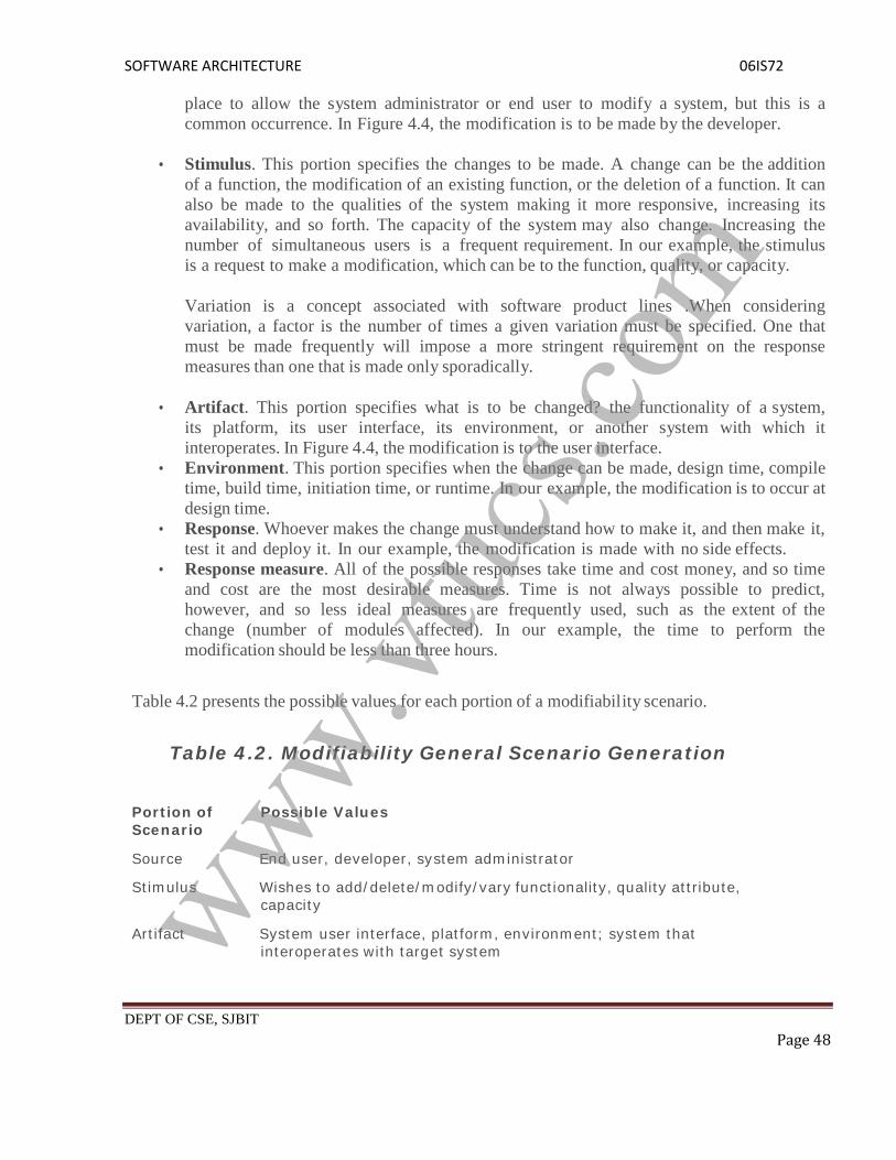
SOFTWARE ARCHITECTURE 06IS72
DEPT OF CSE, SJBIT Page 48
place to allow the system administrator or end user to modify a system, but this is acommon occurrence. In Figure 4.4, the modification is to be made by the developer.
Stimulus. This portion specifies the changes to be made. A change can be the additionof a function, the modification of an existing function, or the deletion of a function. It canalso be made to the qualities of the system making it more responsive, increasing itsavailability, and so forth. The capacity of the system may also change. Increasing thenumber of simultaneous users is a frequent requirement. In our example, the stimulusis a request to make a modification, which can be to the function, quality, or capacity.
Variation is a concept associated with software product lines .When consideringvariation, a factor is the number of times a given variation must be specified. One thatmust be made frequently will impose a more stringent requirement on the responsemeasures than one that is made only sporadically.
Artifact. This portion specifies what is to be changed? the functionality of a system,its platform, its user interface, its environment, or another system with which itinteroperates. In Figure 4.4, the modification is to the user interface.
Environment. This portion specifies when the change can be made, design time, compiletime, build time, initiation time, or runtime. In our example, the modification is to occur atdesign time.
Response. Whoever makes the change must understand how to make it, and then make it,test it and deploy it. In our example, the modification is made with no side effects.
Response measure. All of the possible responses take time and cost money, and so timeand cost are the most desirable measures. Time is not always possible to predict,however, and so less ideal measures are frequently used, such as the extent of thechange (number of modules affected). In our example, the time to perform themodification should be less than three hours.
Table 4.2 presents the possible values for each portion of a modifiability scenario.
Table 4.2. Modifiability General Scenario Generation
Portion ofScenario
Possible Values
Source End user, developer, system administrator
Stimulus Wishes to add/delete/modify/vary functionality, quality attribute,capacity
Artifact System user interface, platform, environment; system thatinteroperates with target systemwww.vt
ucs.c
om

SOFTWARE ARCHITECTURE06IS72
DEPT OF CSE, SJBIT Page 49
Environment At runtime, compile time, build time, design time
Response Locates places in architecture to be modified; makes modificationwithout affecting other functionality; tests modification; deploysmodification
ResponseMeasure
Cost in terms of number of elements affected, effort, money;extent to which this affects other functions or quality attributes
www.vtuc
s.com

SOFTWARE ARCHITECTURE 06IS72
DEPT OF CSE, SJBIT Page 50
PERFORMANCE
Performance is about timing. Events (interrupts, messages, requests from users, or thepassage of time) occur, and the system must respond to them. There are a variety ofcharacterizations of event arrival and the response but basically performance is concernedwith how long it takes the system to respond when an event occurs.
One of the things that make performance complicated is the number of event sources andarrival patterns. Events can arrive from user requests, from other systems, or from withinthe system. A Web-based financial services system gets events from its users (possiblynumbering in the tens or hundreds of thousands). An engine control system gets itsrequests from the passage of time and must control both the firing of the ignition when acylinder is in the correct position and the mixture of the fuel to maximize power andminimize pollution.
For the Web-based financial system, the response might be the number of transactionsthat can be processed in a minute. For the engine control system, the response might bethe variation in the firing time. In each case, the pattern of events arriving and the patternof responses can be characterized, and this characterization forms the language withwhich to construct general performance scenarios.
A performance scenario begins with a request for some service arriving at the system.Satisfying the request requires resources to be consumed. While this is happening thesystem may be simultaneously servicing other requests.
An arrival pattern for events may be characterized as either periodic or stochastic. Forexample, a periodic event may arrive every 10 milliseconds. Periodic event arrival ismost often seen in real-time systems. Stochastic arrival means that events arriveaccording to some probabilistic distribution. Events can also arrive sporadically, that is,according to a pattern not capturable by either periodic or stochastic characterizations.
Multiple users or other loading factors can be modeled by varying the arrival pattern forevents. In other words, from the point of view of system performance, it does not matterwhether one user submits 20 requests in a period of time or whether two users eachsubmit 10. What matters is the arrival pattern at the server and dependencies within therequests.
The response of the system to a stimulus can be characterized by latency (the timebetween the arrival of the stimulus and the system's response to it), deadlines in processing(in the engine controller, for example, the fuel should ignite when the cylinder is in aparticular position, thus introducing a processing deadline)www.vt
ucs.c
om

SOFTWARE ARCHITECTURE 06IS72
DEPT OF CSE, SJBIT Page 51
the throughput of the system (e.g., the number of transactions the system can process in asecond), the jitter of the response (the variation in latency), the number of events notprocessed because the system was too busy to respond, and
the data that was lost because the system was too busy.
Notice that this formulation does not consider whether the system is networked orstandalone. Nor does it (yet) consider the configuration of the system or the consumption ofresources.
Performance General Scenarios
From these considerations we can see the portions of the performance general scenario, anexample of which is shown in Figure 4.5: "Users initiate 1,000 transactions per minutestochastically under normal operations, and these transactions are processed with an averagelatency of two seconds."
Figure 4.5. Sample performance scenario
Source of stimulus. The stimuli arrive either from external (possibly multiple) or internalsources. In our example, the source of the stimulus is a collection of users.
Stimulus. The stimuli are the event arrivals. The arrival pattern can be characterized asperiodic, stochastic, or sporadic. In our example, the stimulus is the stochastic initiationof 1,000 transactions per minute.
Artifact. The artifact is always the system's services, as it is in our example. Environment.
The system can be in various operational modes, such as normal,emergency, or overload. In our example, the system is in normal mode.www.vt
ucs.c
om

SOFTWARE ARCHITECTURE 06IS72
DEPT OF CSE, SJBIT Page 52
Response. The system must process the arriving events. This may cause a change in thesystem environment (e.g., from normal to overload mode). In our example, the transactionsare processed.
Response measure. The response measures are the time it takes to process the arrivingevents, the variation in this time (jitter), the number of events that can be processed within aparticular time interval (throughput), or a characterization of the events that cannot beprocessed (miss rate, data loss). In our example, the transactions should be processed withan average latency of two seconds.
SECURITY
Security is a measure of the system's ability to resist unauthorized usage while still providing itsservices to legitimate users. An attempt to breach security is called an attack and can take anumber of forms. It may be an unauthorized attempt to access data or services or to modify data,or it may be intended to deny services to legitimate users.
Some security experts use "threat" interchangeably with "attack."
Attacks, often occasions for wide media coverage, may range from theft of money by electronictransfer to modification of sensitive data, from theft of credit card numbers to destruction of fileson computer systems, or to denial-of-service attacks carried out by worms or viruses. Still, theelements of a security general scenario are the same as the elements of our other generalscenarios a stimulus and its source, an environment, the target under attack, the desired responseof the system, and the measure of this response.
Security can be characterized as a system providing non repudiation, confidentiality, integrity,assurance, availability, and auditing. For each term, we provide a definition and an example.
Non repudiation is the property that a transaction (access to or modification of data orservices) cannot be denied by any of the parties to it. This means you cannot deny that youordered that item over the Internet if, in fact, you did.
Confidentiality is the property that data or services are protected fromunauthorized access. This means that a hacker cannot access your income tax returns on agovernment computer.
Integrity is the property that data or services are being delivered as intended. This meansthat your grade has not been changed since your instructor assigned it.
Assurance is the property that the parties to a transaction are who they purport to be. Thismeans that, when a customer sends a credit card number to an Internet merchant, themerchant is who the customer thinks they are. Availability is the property that the systemwill be available for legitimate use.
Auditing is the property that the system tracks activities within it at levelswww.vtuc
s.com

SOFTWARE ARCHITECTURE 06IS72
DEPT OF CSE, SJBIT Page 53
sufficient to reconstruct them. This means that, if you transfer money out of one accountto another account, in Switzerland, the system will maintain a record of that transfer.
Each of these security categories gives rise to a collection of general scenarios.
Security General Scenarios
The portions of a security general scenario are given below. Figure 4.6 presents an example. Acorrectly identified individual tries to modify system data from an external site; system maintainsan audit trail and the correct data is restored within one day.
Source of stimulus. The source of the attack may be either a human or another system. Itmay have been previously identified (either correctly or incorrectly) or may be currentlyunknown.
If the source of the attack is highly motivated (say politically motivated), then defensivemeasures such as "We know who you are and will prosecute you" are not likely to beeffective; in such cases the motivation of the user may be important. If the source hasaccess to vast resources (such as a government), then defensive measures are verydifficult. The attack itself is unauthorized access, modification, or denial of service.
The difficulty with security is allowing access to legitimate users and determininglegitimacy. If the only goal were to prevent access to a system, disallowing all access would bean effective defensive measure.
Figure 4.6. Sample security scenario
Stimulus. The stimulus is an attack or an attempt to break security. We characterize this asan unauthorized person or system trying to display information, change and/or deleteinformation, access services of the system, or reduce availability of system services. InFigure 4.6, the stimulus is an attempt to modify data.www.vt
ucs.c
om
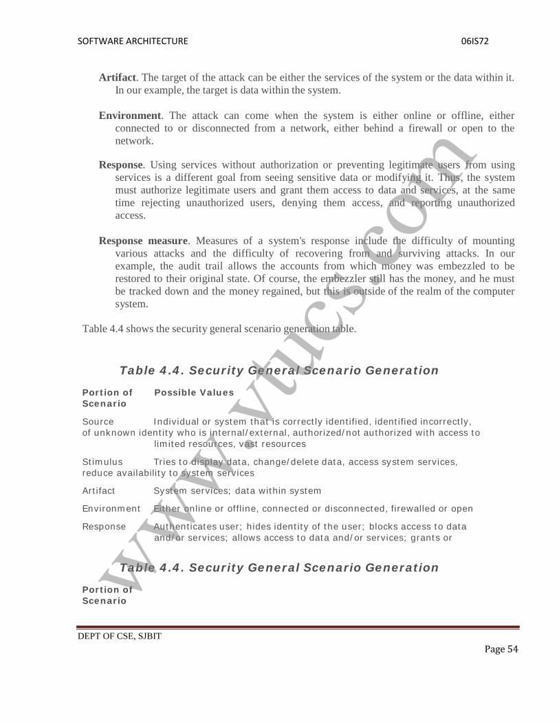
SOFTWARE ARCHITECTURE 06IS72
DEPT OF CSE, SJBIT Page 54
Artifact. The target of the attack can be either the services of the system or the data within it.In our example, the target is data within the system.
Environment. The attack can come when the system is either online or offline, eitherconnected to or disconnected from a network, either behind a firewall or open to thenetwork.
Response. Using services without authorization or preventing legitimate users from usingservices is a different goal from seeing sensitive data or modifying it. Thus, the systemmust authorize legitimate users and grant them access to data and services, at the sametime rejecting unauthorized users, denying them access, and reporting unauthorizedaccess.
Response measure. Measures of a system's response include the difficulty of mountingvarious attacks and the difficulty of recovering from and surviving attacks. In ourexample, the audit trail allows the accounts from which money was embezzled to berestored to their original state. Of course, the embezzler still has the money, and he mustbe tracked down and the money regained, but this is outside of the realm of the computersystem.
Table 4.4 shows the security general scenario generation table.
Table 4.4. Security General Scenario Generation
Portion ofScenario
Possible Values
Source Individual or system that is correctly identified, identified incorrectly,of unknown identity who is internal/external, authorized/not authorized with access to
limited resources, vast resources
Stimulus Tries to display data, change/delete data, access system services,reduce availability to system services
Artifact System services; data within system
Environment Either online or offline, connected or disconnected, firewalled or open
Response Authenticates user; hides identity of the user; blocks access to dataand/or services; allows access to data and/or services; grants or
Table 4.4. Security General Scenario Generation
Portion ofScenariowww.vt
ucs.c
om

SOFTWARE ARCHITECTURE06IS72
DEPT OF CSE, SJBIT Page 55
ResponseMeasure
Possible Values
withdraws permission to access data and/or services; recordsaccess/modifications or attempts to access/modify data/services byidentity; stores data in an unreadable format; recognizes anunexplainable high demand for services, and informs a user oranother system, and restricts availability of services
Time/effort/resources required to circumvent security measures withprobability of success; probability of detecting attack; probability ofidentifying individual responsible for attack or access/modification ofdata and/or services; percentage of services still available underdenial-of-services attack; restore data/services; extent to whichdata/services damaged and/or legitimate access denied
www.vtuc
s.com

SOFTWARE ARCHITECTURE 06IS72
DEPT OF CSE, SJBIT Page 56
TESTABILITY
Software testability refers to the ease with which software can be made to demonstrate itsfaults through (typically execution-based) testing. At least 40% of the cost of developingwell-engineered systems is taken up by testing. If the software architect can reduce thiscost, the payoff is large.
In particular, testability refers to the probability, assuming that the software has at leastone fault, that it will fail on its next test execution. Of course, calculating this probability isnot easy and, when we get to response measures, other measures will be used.
For a system to be properly testable, it must be possible to control each component'sinternal state and inputs and then to observe its outputs. Frequently this is done throughuse of a test harness, specialized software designed to exercise the software under test.This may be as simple as a playback capability for data recorded across various interfacesor as complicated as a testing chamber for an engine.
Testing is done by various developers, testers, verifiers, or users and is the last step ofvarious parts of the software life cycle. Portions of the code, the design, or the completesystem may be tested. The response measures for testability deal with how effective thetests are in discovering faults and how long it takes to perform the tests to some desiredlevel of coverage.
Testability General Scenarios
Figure 4.7 is an example of a testability scenario concerning the performance of a unit test: Aunit tester performs a unit test on a completed system component that provides an interface forcontrolling its behavior and observing its output; 85% path coverage is achieved within threehours.
Figure 4.7. Sample testability scenario
Source of stimulus. The testing is performed by unit testers, integration testers, systemwww.vtuc
s.com

SOFTWARE ARCHITECTURE 06IS72
DEPT OF CSE, SJBIT Page 57
testers, or the client. A test of the design may be performed by other developers or by anexternal group. In our example, the testing is performed by a tester.
Stimulus. The stimulus for the testing is that a milestone in the development process is met.This might be the completion of an analysis or design increment, the completion of acoding increment such as a class, the completed integration of a subsystem, or thecompletion of the whole system. In our example, the testing is triggered by thecompletion of a unit of code.
Artifact. A design, a piece of code, or the whole system is the artifact being tested. In ourexample, a unit of code is to be tested.
Environment. The test can happen at design time, at development time, at compile time, orat deployment time. In Figure 4.7, the test occurs during development.
Response. Since testability is related to observability and controllability, the desiredresponse is that the system can be controlled to perform the desired tests and that theresponse to each test can be observed. In our example, the unit can be controlledand its responses captured.
Response measure. Response measures are the percentage of statements that have beenexecuted in some test, the length of the longest test chain (a measure of the difficulty ofperforming the tests), and estimates of the probability of finding additional faults. InFigure 4.7, the measurement is percentage coverage of executable statements.
Table 4.5 gives the testability general scenario generation table.
Table 4.5. Testability General Scenario Generation
Portion ofScenario
Possible Values
www.vtuc
s.com

SOFTWARE ARCHITECTURE 06IS72
DEPT OF CSE, SJBIT Page 58
Source Unit developer Increment integrator
System verifier
Client acceptance testerSystem user
Stimulus Analysis, architecture, design, class, subsystem integration completed; systemdelivered
Artifact Piece of design, piece of code, complete application
Environment At design time, at development time, at compile time, at deployment time
Response Provides access to state values; provides computed values;prepares test environment
Response Measure Percent executable statements executedProbability of failure if fault exists,Time to perform tests, Length of longest dependency ,hainin a test, Length of time to prepare test environment
USABILITY
Usability is concerned with how easy it is for the user to accomplish a desired task and the kindof user support the system provides. It can be broken down into the following areas:
Learning system features. If the user is unfamiliar with a particular system or aparticular aspect of it, what can the system do to make the task of learning easier?
Using a system efficiently. What can the system do to make the user more efficient in itsoperation?
Minimizing the impact of errors. What can the system do so that a user error has minimalimpact?
Adapting the system to user needs. How can the user (or the system itself) adapt to makethe user's task easier?
Increasing confidence and satisfaction. What does the system do to give the userconfidence that the correct action is being taken?
In the last five years, our understanding of the relation between usability and softwarearchitecture has deepened (see the sidebar Usability Mea Culpa). The normaldevelopment process detects usability problems through building prototypes and user testing.The later a problem is discovered and the deeper into the architecture its repair must be made,the more the repair is threatened by time and budget pressures. In our scenarios we focus onaspects of usability that have a major impact on the architecture. Consequently, these scenariosmust be correct prior to the architectural design so that they will not be discovered during usertesting or prototyping.www.vt
ucs.c
om

SOFTWARE ARCHITECTURE 06IS72
DEPT OF CSE, SJBIT Page 59
Usability General ScenariosFigure 4.8 gives an example of a usability scenario: A user, wanting to minimize the impact ofan error, wishes to cancel a system operation at runtime; cancellation takes place in less than onesecond. The portions of the usability general scenarios are:
Source of stimulus. The end user is always the source of the stimulus.
Stimulus. The stimulus is that the end user wishes to use a system efficiently, learn to use thesystem, minimize the impact of errors, adapt the system, or feel comfortable with thesystem. In our example, the user wishes to cancel an operation, which is an exampleof minimizing the impact of errors.
Artifact. The artifact is always the system.
Environment. The user actions with which usability is concerned always occur at runtime orat system configuration time. Any action that occurs before then is performed bydevelopers and, although a user may also be the developer, we distinguish between theseroles even if performed by the same person. In Figure4.8, the cancellation occurs at runtime.
Response. The system should either provide the user with the features needed or anticipatethe user's needs. In our example, the cancellation occurs as the user wishes and thesystem is restored to its prior state.
Response measure. The response is measured by task time, number of errors, numberof problems solved, user satisfaction, gain of user knowledge, ratio of successfuloperations to total operations, or amount of time/data lost when an error occurs. InFigure 4.8, the cancellation should occur in less than one second.
Figure 4.8. Sample usability scenario
Theusabilitygeneralscenario
generation table is given in Table 4.6.
Table 4.6. Usability General Scenario Generationwww.vtuc
s.com

SOFTWARE ARCHITECTURE 06IS72
DEPT OF CSE, SJBIT Page 60
Portion of Possible Values
ScenarioSource End user
Stimulus At runtime or configure time System provides one or more of the following responses:to support "learn system features"
Response Wants to learn system features; efficiently; minimize impact of errors; adapt system; feelcomfortable
Artifact System help system is sensitive to context; interface is familiar to user;interface is usable in an unfamiliar
contextto support "use system efficiently
Table 4.7. Quality Attribute Stimuli
QualityAttribute
Stimulus
Availability Unexpected event, nonoccurrence of expected event
Modifiability Request to add/delete/change/vary functionality, platform, quality attribute, or capacity
Performance Periodic, stochastic, or sporadic
Security Tries to
display, modify, change/delete information, access, or reduce availability to systemservices
Testability Completion of phase of system development
Table 4.7 gives the stimuli possible for each of the attributes and shows a number of differentconcepts. Some stimuli occur during runtime and others occur before. The problem for thearchitect is to understand which of these stimuli represent the same occurrence, which areaggregates of other stimuli, and which are independent.
Once the relations are clear, the architect can communicate them to the various stakeholdersusing language that each comprehends. We cannot give the relations among stimuli in a generalway because they depend partially on environment. A performance event may be atomic or maybe an aggregate of other lower-level occurrences; a failure may be a single performance event oran aggregate.
For example, it may occur with an exchange of several messages between a client and a server(culminating in an unexpected message), each of which is an atomic event from a performanceperspective.
Business Qualities :
In addition to the qualities that apply directly to a system, a number of business quality goalsfrequently shape a system's architecture. These goals center on cost, schedule, market, andmarketing considerations. Each suffers from the same ambiguity that system qualities have, and
www.vtuc
s.com

SOFTWARE ARCHITECTURE 06IS72
DEPT OF CSE, SJBIT Page 61
they need to be made specific with scenarios in order to make them suitable for influencing thedesign process and to be made testable. Here, we present them as generalities, however, andleave the generation of scenarios as one of our discussion questions.
Time to market. If there is competitive pressure or a short window ofopportunity for a system or product, development time becomes important. This in turnleads to pressure to buy or otherwise re-use existing elements. Time to market is oftenreduced by using prebuilt elements such as commercial off-the- shelf (COTS) products orelements re-used from previous projects. The ability to insert or deploy a subset of thesystem depends on the decomposition of the system into elements.
Cost and benefit. The development effort will naturally have a budget that must not beexceeded. Different architectures will yield different development costs. For instance,an architecture that relies on technology (or expertise with a technology) not resident inthe developing organization will be more expensive to realize than one that takesadvantage of assets already inhouse. An architecture that is highly flexible will typicallybe more costly to build than one that is rigid (although it will be less costly to maintainand modify).
Projected lifetime of the system. If the system is intended to have a longlifetime, modifiability, scalability, and portability become important. But buildingin the additional infrastructure (such as a layer to support portability) will usuallycompromise time to market. On the other hand, a modifiable, extensible product is morelikely to survive longer in the marketplace, extending its lifetime.
Targeted market. For general-purpose (mass-market) software, the platforms on which asystem runs as well as its feature set will determine the size of the potential market.Thus, portability and functionality are key to market share. Other qualities, such asperformance, reliability, and usability also play a role. To attack a large market with acollection of related products, a product line approach should be considered in which acore of the system is common (frequently including provisions for portability) andaround which layers of software of increasing specificity are constructed.
Rollout schedule. If a product is to be introduced as base functionality with many featuresreleased later, the flexibility and customizability of the architecture are important.Particularly, the system must be constructed with ease of expansion and contraction inmind.
Integration with legacy systems. If the new system has to integrate with existingsystems, care must be taken to define appropriate integration mechanisms. This propertyis clearly of marketing importance but has substantial architectural implications. Forexample, the ability to integrate a legacy system with an HTTP server to make itaccessible from the Web has been a marketing goal in many corporations over the pastdecade. The architectural constraints implied by this integration must be analyzed.
www.vtuc
s.com

SOFTWARE ARCHITECTURE 06IS72
DEPT OF CSE, SJBIT Page 62
Architecture Qualities :
In addition to qualities of the system and qualities related to the business environment inwhich the system is being developed, there are also qualities directly related to thearchitecture itself that are important to achieve.
Conceptual integrity is the underlying theme or vision that unifies the design of thesystem at all levels. The architecture should do similar things in similar ways. FredBrooks writes emphatically that a system's conceptual integrity is of overridingimportance, and that systems without it fail:
Correctness and completeness are essential for the architecture to allow for all of thesystem's requirements and runtime resource constraints to be met
Buildability allows the system to be completed by the available team in a timely mannerand to be open to certain changes as development progresses. It refers to the ease ofconstructing a desired system and is achieved architecturally by paying careful attentionto the decomposition into modules, judiciously assigning of those modules todevelopment teams, and limiting the dependencies between the modules (and hence theteams). The goal is to maximize the parallelism that can occur in development.
Because buildability is usually measured in terms of cost and time, there is a relationshipbetween it and various cost models. However, buildability is more complex than what isusually covered in cost models. A system is created from certain materials, and thesematerials are created using a variety of tools.
Chapter 5. Achieving Quality
Introducing Tactics :
What is it that imparts portability to one design, high performance to another, andintegrability to a third? The achievement of these qualities relies on fundamental designdecisions. We will examine these design decisions, which we call tactics. A tactic is a designdecision that influences the control of a quality attribute response.
A system design consists of a collection of decisions. Some of these decisions help controlthe quality attribute responses; others ensure achievement of system functionality. In this section,we discuss the quality attribute decisions known as tactics. We represent this relationship inFigure 5.1. The tactics are those that architects have been using for years, and we isolate anddescribe them. We are not inventing tactics here, just capturing what architects do in practice.
Figure 5.1. Tactics are intended to control responses to stimuli.www.vtuc
s.com

SOFTWARE ARCHITECTURE 06IS72
DEPT OF CSE, SJBIT Page 63
Each tactic is a design option for the architect. For example, one of the tactics introducesredundancy to increase the availability of a system. This is one option the architect has to increaseavailability, but not the only one. Usually achieving high availability through redundancyimplies a concomitant need for synchronization (to ensure that the redundant copy can be used ifthe original fails). We see two immediate ramifications of this example.
1. Tactics can refine other tactics. We identified redundancy as a tactic. As such, it can berefined into redundancy of data (in a database system) or redundancy of computation (inan embedded control system). Both types are also tactics. There are further refinementsthat a designer can employ to make each type of redundancy more concrete. For eachquality attribute that we discuss, we organize the tactics as a hierarchy.
2. Patterns package tactics. A pattern that supports availability will likely use both aredundancy tactic and a synchronization tactic. It will also likely use more concreteversions of these tactics. At the end of this section, we present an example of apattern described in terms of its tactics.
Availability Tactics :
A failure occurs when the system no longer delivers a service that is consistent with itsspecification; this failure is observable by the system's users. A fault (or combination of faults)has the potential to cause a failure. Recall also that recovery or repair is an important aspect ofavailability. The tactics we discuss in this section will keep faults from becoming failures or atleast bound the effects of the fault and make repair possible. We illustrate this in Figure 5.2.
Figure 5.2. Goal of availability tactics
Many of the tactics we discuss are available within standard execution environments such asoperating systems, application servers, and database management systems. It is still important tounderstand the tactics used so that the effects of using a particular one can be considered duringdesign and evaluation. All approaches to maintaining availability involve some type ofredundancy, some type of health monitoring to detect a failure, and some type of recovery when
www.vtuc
s.com

SOFTWARE ARCHITECTURE 06IS72
DEPT OF CSE, SJBIT Page 64
a failure is detected. In some cases, the monitoring or recovery is automatic and in others it ismanual.
FAULT DETECTION
Three widely used tactics for recognizing faults are ping/echo, heartbeat, and exceptions.
Ping/echo. One component issues a ping and expects to receive back an echo, within apredefined time, from the component under scrutiny. This can be used within a group ofcomponents mutually responsible for one task. It can also used be used by clients toensure that a server object and the communication path to the server are operating withinthe expected performance bounds. "Ping/echo" fault detectors can be organized in ahierarchy, in which a lowest-level detector pings the software processes with which itshares a processor, and the higher-level fault detectors ping lower-level ones. This usesless communications bandwidth than a remote fault detector that pings all processes.
Heartbeat (dead man timer). In this case one component emits a heartbeatmessage periodically and another component listens for it. If the heartbeat fails, theoriginating component is assumed to have failed and a fault correction component isnotified. The heartbeat can also carry data. For example, an automated teller machine canperiodically send the log of the last transaction to a server. This message not only acts asa heartbeat but also carries data to be processed.
The ping/echo and heartbeat tactics operate among distinct processes, and the exception tacticoperates within a single process. The exception handler will usually perform a semantictransformation of the fault into a form that can be processed.
FAULT RECOVERY
Fault recovery consists of preparing for recovery and making the system repair. Somepreparation and repair tactics follow.
Voting. Processes running on redundant processors each take equivalent input and compute asimple output value that is sent to a voter. If the voter detects deviant behavior from asingle processor, it fails it.
o The voting algorithm can be "majority rules" or "preferred component" or someother algorithm. This method is used to correct faulty operation of algorithms orfailure of a processor and is often used in control systems. If all of the processorsutilize the same algorithms, the redundancy detects only a processor fault and notan algorithm fault. Thus, if the consequence of a failure is extreme, such aspotential loss of life, the redundant components can be diverse.
o One extreme of diversity is that the software for each redundant component isdeveloped by different teams and executes on dissimilar platforms. Less extreme isto develop a single software component on dissimilar platforms.
www.vtuc
s.com

SOFTWARE ARCHITECTURE 06IS72
DEPT OF CSE, SJBIT Page 65
o Diversity is expensive to develop and maintain and is used only in exceptionalcircumstances, such as the control of surfaces on aircraft. It is usually used forcontrol systems in which the outputs to the voter are straightforward and easy toclassify as equivalent or deviant, the computations are cyclic, and all redundantcomponents receive equivalent inputs from sensors.
o Diversity has no downtime when a failure occurs since the voter continues tooperate. Variations on this approach include the Simplex approach, which uses theresults of a "preferred" component unless they deviate from those of a "trusted"component, to which it defers. Synchronization among the redundant componentsis automatic since they are all assumed to be computing on the same set of inputs inparallel.
Active redundancy (hot restart).
All redundant components respond to events in parallel. Consequently, they are all inthe same state. The response from only one component is used (usually the first torespond), and the rest are discarded. When a fault occurs, the downtime of systemsusing this tactic is usually milliseconds since the backup is current and the only timeto recover is the switching time.
Active redundancy is often used in a client/server configuration, such as databasemanagement systems, where quick responses are necessary even when a fault occurs.In a highly available distributed system, the redundancy may be in thecommunication paths. For example, it may be desirable to use a LAN with a numberof parallel paths and place each redundant component in a separate path. In this case,a single bridge or path failure will not make all of the system's componentsunavailable.
Synchronization is performed by ensuring that all messages to any redundantcomponent are sent to all redundant components. If communication has a possibilityof being lost (because of noisy or overloaded communication lines), a reliabletransmission protocol can be used to recover. A reliable transmission protocolrequires all recipients to acknowledge receipt together with some integrityindication such as a checksum.
If the sender cannot verify that all recipients have received the message, it willresend the message to those components not acknowledging receipt. The resending ofunreceived messages (possibly over different communication paths) continues untilthe sender marks the recipient as out of service.
Passive redundancy
o One component (the primary) responds to events and informs the othercomponents (the standbys) of state updates they must make. When a fault occurs,the system must first ensure that the backup state is sufficiently fresh beforeresuming services.
www.vtuc
s.com

SOFTWARE ARCHITECTURE 06IS72
DEPT OF CSE, SJBIT Page 66
o This approach is also used in control systems, often when the inputs come overcommunication channels or from sensors and have to be switched from the primaryto the backup on failure. This tactic depends on the standby components takingover reliably.
o Forcing switchovers periodically for example, once a day or once a week increasesthe availability of the system. Some database systems force a switch with storage ofevery new data item. The new data item is stored in a shadow page and the oldpage becomes a backup for recovery. In this case, the downtime can usually belimited to seconds.
o Synchronization is the responsibility of the primary component, which may useatomic broadcasts to the secondaries to guarantee synchronization.
Spare. A standby spare computing platform is configured to replace many different failedcomponents. It must be rebooted to the appropriate software configuration and have itsstate initialized when a failure occurs.
Making a checkpoint of the system state to a persistent device periodically and logging allstate changes to a persistent device allows for the spare to be set to the appropriatestate. This is often used as the standby client workstation, where the user can move whena failure occurs. The downtime for this tactic is usually minutes.
There are tactics for repair that rely on component reintroduction. When a redundantcomponent fails, it may be reintroduced after it has been corrected. Such tactics areshadow operation, state resynchronization, and rollback.
Shadow operation. A previously failed component may be run in "shadow mode" for a shorttime to make sure that it mimics the behavior of the working components before restoringit to service.
State resynchronization. The passive and active redundancy tactics require thecomponent being restored to have its state upgraded before its return to service. Theupdating approach will depend on the downtime that can be sustained, the size of theupdate, and the number of messages required for the update. A single message containingthe state is preferable, if possible. Incremental state upgrades, with periods of servicebetween increments, lead to complicated software.
Checkpoint/rollback. A checkpoint is a recording of a consistent state created eitherperiodically or in response to specific events. Sometimes a system fails in an unusualmanner, with a detectably inconsistent state. In this case, the system should be restoredusing a previous checkpoint of a consistent state and a log of the transactions thatoccurred since the snapshot was taken.
FAULT PREVENTIONThe following are some fault prevention tactics.
www.vtuc
s.com

SOFTWARE ARCHITECTURE 06IS72
DEPT OF CSE, SJBIT Page 67
Removal from service. This tactic removes a component of the system from operation toundergo some activities to prevent anticipated failures. One example is rebooting acomponent to prevent memory leaks from causing a failure. If this removal from serviceis automatic, an architectural strategy can be designed to support it. If it is manual, thesystem must be designed to support it.
Transactions. A transaction is the bundling of several sequential steps such that the entirebundle can be undone at once. Transactions are used to prevent any data from beingaffected if one step in a process fails and also to prevent collisions among severalsimultaneous threads accessing the same data.
Process monitor. Once a fault in a process has been detected, a monitoring process candelete the nonperforming process and create a new instance of it, initialized to someappropriate state as in the spare tactic.
Modifiability Tactics :
Tactics to control modifiability have as their goal controlling the time and cost toimplement, test, and deploy changes. Figure 5.4 shows this relationship.
Figure 5.4. Goal of modifiability tactics
We organize the tactics for modifiability in sets according to their goals. One set has as its goalreducing the number of modules that are directly affected by a change. We call this set "localizemodifications." A second set has as its goal limiting modifications to the localized modules. Weuse this set of tactics to "prevent the ripple effect." Implicit in this distinction is that there aremodules directly affected (those whose responsibilities are adjusted to accomplish the change)and modules indirectly affected by a change (those whose responsibilities remain unchanged butwhose implementation must be changed to accommodate the directly affected modules). Athird set of tactics has as its goal controlling deployment time and cost. We call this set "deferbinding time."
LOCALIZE MODIFICATIONS
Although there is not necessarily a precise relationship between the number of modules affectedby a set of changes and the cost of implementing those changes, restricting modifications to asmall set of modules will generally reduce the cost. The goal of tactics in this set is to assign
www.vtuc
s.com

SOFTWARE ARCHITECTURE 06IS72
DEPT OF CSE, SJBIT Page 68
responsibilities to modules during design such that anticipated changes will be limited in scope.We identify five such tactics.
Maintain semantic coherence.o Semantic coherence refers to the relationships among responsibilities in a module.
The goal is to ensure that all of these responsibilities work together withoutexcessive reliance on other modules. Achievement of this goal comes fromchoosing responsibilities that have semantic coherence.
o Coupling and cohesion metrics are an attempt to measure semantic coherence, butthey are missing the context of a change. Instead, semantic coherence should bemeasured against a set of anticipated changes. One subtactic is to abstractcommon services. Providing common services through specialized modules isusually viewed as supporting re-use.
o This is correct, but abstracting common services also supports modifiability. Ifcommon services have been abstracted, modifications to them will need to be madeonly once rather than in each module where the services are used. Furthermore,modification to the modules using those services will not impact other users.
o This tactic, then, supports not only localizing modifications but also the preventionof ripple effects. Examples of abstracting common services are the use ofapplication frameworks and the use of other middleware software.
Anticipate expected changes.
Considering the set of envisioned changes provides a way to evaluate a particularassignment of responsibilities. The basic question is "For each change, does the proposeddecomposition limit the set of modules that need to be modified to accomplish it?"
An associated question is "Do fundamentally different changes affect the samemodules?" How is this different from semantic coherence? Assigning responsibilitiesbased on semantic coherence assumes that expected changes will be semanticallycoherent.
The tactic of anticipating expected changes does not concern itself with the coherenceof a module's responsibilities but rather with minimizing the effects of thechanges. In reality this tactic is difficult to use by itself since it is not possible toanticipate all changes. For that reason, it is usually used in conjunction with semanticcoherence.
Generalize the module. Making a module more general allows it to compute a broaderrange of functions based on input. The input can be thought of as defining a language forthe module, which can be as simple as making constants input parameters or ascomplicated as implementing the module as an interpreter and making the inputparameters be a program in the interpreter's language. The more general a module, the
www.vtuc
s.com

SOFTWARE ARCHITECTURE 06IS72
DEPT OF CSE, SJBIT Page 69
more likely that requested changes can be made by adjusting the input languagerather than by modifying the module.
Limit possible options. Modifications, especially within a product line may be farranging and hence affect many modules. Restricting the possible options will reduce theeffect of these modifications. For example, a variation point in a product line may beallowing for a change of processor. Restricting processor changes to members of the samefamily limits the possible options.
PREVENT RIPPLE EFFECTS
A ripple effect from a modification is the necessity of making changes to modules not directlyaffected by it. For instance, if module A is changed to accomplish a particular modification, thenmodule B is changed only because of the change to module A. B has to be modified because itdepends, in some sense, on A.
We begin our discussion of the ripple effect by discussing the various types of dependencies thatone module can have on another. We identify eight types:
1. Syntax of
- data. For B to compile (or execute) correctly, the type (or format) of the data that isproduced by A and consumed by B must be consistent with the type (or format) of dataassumed by B.
- service. For B to compile and execute correctly, the signature of servicesprovided by A and invoked by B must be consistent with the assumptions of B.
2. Semantics of
- data. For B to execute correctly, the semantics of the data produced by A and consumedby B must be consistent with the assumptions of B.
- service. For B to execute correctly, the semantics of the services produced by Aand used by B must be consistent with the assumptions of B.
3. Sequence of
- data. For B to execute correctly, it must receive the data produced by A in a fixedsequence. For example, a data packet's header must precede its body in order ofreception (as opposed to protocols that have the sequence number built into the data).
- control. For B to execute correctly, A must have executed previously within certaintiming constraints. For example, A must have executed no longer than 5ms before Bexecutes.
www.vtuc
s.com

SOFTWARE ARCHITECTURE 06IS72
DEPT OF CSE, SJBIT Page 70
4. Identity of an interface of A. A may have multiple interfaces. For B to compile andexecute correctly, the identity (name or handle) of the interface must be consistent withthe assumptions of B.
5. Location of A (runtime). For B to execute correctly, the runtime location of A must beconsistent with the assumptions of B. For example, B may assume that A is located in adifferent process on the same processor.
6. Quality of service/data provided by A. For B to execute correctly, some propertyinvolving the quality of the data or service provided by A must be consistent withB's assumptions. For example, data provided by a particular sensor must have a certainaccuracy in order for the algorithms of B to work correctly.
7. Existence of A. For B to execute correctly, A must exist. For example, if B is requestinga service from an object A, and A does not exist and cannot be dynamicallycreated, then B will not execute correctly.
8. Resource behavior of A. For B to execute correctly, the resource behavior of A must beconsistent with B's assumptions. This can be either resource usage of A (A uses the samememory as B) or resource ownership (B reserves a resource that A believes it owns).
With this understanding of dependency types, we can now discuss tactics available to thearchitect for preventing the ripple effect for certain types.
Hide information. Information hiding is the decomposition of the responsibilities for anentity (a system or some decomposition of a system) into smaller pieces and choosingwhich information to make private and which to make public. The public responsibilitiesare available through specified interfaces.
The goal is to isolate changes within one module and prevent changes from propagatingto others. This is the oldest technique for preventing changes from propagating. It isstrongly related to "anticipate expected changes" because it uses those changes as thebasis for decomposition.
Maintain existing interfaces. If B depends on the name and signature of aninterface of A, maintaining this interface and its syntax allows B to remainunchanged. Of course, this tactic will not necessarily work if B has a semanticdependency on A, since changes to the meaning of data and services are difficult tomask.
Also, it is difficult to mask dependencies on quality of data or quality of service, resourceusage, or resource ownership. Interface stability can also be achieved by separating theinterface from the implementation. This allows the creation of abstract interfaces thatmask variations. Variations can be embodied within the existing responsibilities, or theycan be embodied by replacing one implementation of a module with another.
Patterns that implement this tactic include
- adding interfaces. Most programming languages allow multiple interfaces. Newly
www.vtuc
s.com

SOFTWARE ARCHITECTURE 06IS72
DEPT OF CSE, SJBIT Page 71
visible services or data can be made available through new interfaces, allowing existinginterfaces to remain unchanged and provide the same signature.
- adding adapter. Add an adapter to A that wraps A and provides the signature of theoriginal A.
- providing a stub A. If the modification calls for the deletion of A, then providing a stubfor A will allow B to remain unchanged if B depends only on A's signature.
Restrict communication paths. Restrict the modules with which a given module sharesdata. That is, reduce the number of modules that consume data produced by the givenmodule and the number of modules that produce data consumed byit. This will reduce the ripple effect since data production/consumption introducesdependencies that cause ripples.
Use an intermediary. If B has any type of dependency on A other than semantic, it ispossible to insert an intermediary between B and A that manages activities associatedwith the dependency. All of these intermediaries go by different names, but we willdiscuss each in terms of the dependency types we have enumerated. As before, in theworst case, an intermediary cannot compensate for semantic changes. The intermediariesare
- data (syntax). Repositories (both blackboard and passive) act as intermediaries betweenthe producer and consumer of data. The repositories can convert the syntax produced byA into that assumed by B. Some publish/subscribe patterns (those that have data flowingthrough a central component) can also convert the syntax into that assumed by B. TheMVC and PAC patterns convert data in one formalism (input or output device) intoanother (that used by the model in MVC or the abstraction in PAC).
- service (syntax). The facade, bridge, mediator, strategy, proxy, and factory patterns allprovide intermediaries that convert the syntax of a service from one form into another.Hence, they can all be used to prevent changes in A from propagating to B.
- identity of an interface of A. A broker pattern can be used to mask changes in theidentity of an interface. If B depends on the identity of an interface of A and that identitychanges, by adding that identity to the broker and having the broker make the connectionto the new identity of A, B can remain unchanged.
- location of A (runtime). A name server enables the location of A to be changed withoutaffecting B. A is responsible for registering its current location with the name server, andB retrieves that location from the name server.
- resource behavior of A or resource controlled by A. A resource manager is anintermediary that is responsible for resource allocation. Certain resource managers (e.g.,those based on Rate Monotonic Analysis in real-time systems) can guarantee thesatisfaction of all requests within certain constraints. A, of course, must give up control of
www.vtuc
s.com

SOFTWARE ARCHITECTURE 06IS72
DEPT OF CSE, SJBIT Page 72
the resource to the resource manager.
- existence of A. The factory pattern has the ability to create instances as needed, andthus the dependence of B on the existence of A is satisfied by actions of the factory.
DEFER BINDING TIME
The two tactic categories we have discussed thus far are designed to minimize the numberof modules that require changing to implement modifications. Our modifiability scenariosinclude two elements that are not satisfied by reducing the number of modules to be changedtime to deploy and allowing non developers to make changes. Deferringbinding time supports both of those scenarios at the cost of requiring additional infrastructure tosupport the late binding.
Decisions can be bound into the executing system at various times. We discuss those that affectdeployment time. The deployment of a system is dictated by some process. When a modificationis made by the developer, there is usually a testing and distribution process that determines thetime lag between the making of the change and the availability of that change to the end user.
Binding at runtime means that the system has been prepared for that binding and all of thetesting and distribution steps have been completed. Deferring binding time also supports allowingthe end user or system administrator to make settings or provide input that affects behavior.
Many tactics are intended to have impact at load time or runtime, such as the following.
Runtime registration supports plug-and-play operation at the cost of additionaloverhead to manage the registration. Publish/subscribe registration, for example, can beimplemented at either runtime or load time.
Configuration files are intended to set parameters at startup. Polymorphism allows late binding of method calls. Component replacement allows load time binding. Adherence to defined protocols allows runtime binding of independent processes.
The tactics for modifiability are summarized in Figure 5.5.
Figure 5.5. Summary of modifiability tactics
www.vtuc
s.com

SOFTWARE ARCHITECTURE 06IS72
DEPT OF CSE, SJBIT Page 73
Performance Tactics :
The goal of performance tactics is to generate a response to an event arriving at the systemwithin some time constraint. The event can be single or a stream and is the trigger for a request toperform computation. It can be the arrival of a message, the expiration of
a time interval, the detection of a significant change of state in the system's environment, and soforth. The system processes the events and generates a response. Performance tactics control thetime within which a response is generated. This is shown in Figure5.6.Latency is the time between the arrival of an event and the generation of a response to it.
Figure 5.6. Goal of performance tactics
After an event arrives, either the system is processing on that event or the processing is blockedfor some reason. This leads to the two basic contributors to the response time: resourceconsumption and blocked time.
1. Resource consumption. Resources include CPU, data stores, networkcommunication bandwidth, and memory, but it can also include entities defined by theparticular system under design. For example, buffers must be managed and access tocritical sections must be made sequential.
Events can be of varying types (as just enumerated), and each type goes through aprocessing sequence. For example, a message is generated by one component, is placed onthe network, and arrives at another component.
It is then placed in a buffer; transformed in some fashion (marshalling is the term theObject Management Group uses for this transformation); processed according to somealgorithm; transformed for output; placed in an output buffer; and sent onward toanother component, another system, or the user. Each of these phases contributes to theoverall latency of the processing of that event.
2. Blocked time. A computation can be blocked from using a resource because ofcontention for it, because the resource is unavailable, or because the computationdepends on the result of other computations that are not yet available.
www.vtuc
s.com

SOFTWARE ARCHITECTURE 06IS72
DEPT OF CSE, SJBIT Page 74
- Contention for resources. Figure 5.6 shows events arriving at the system. Theseevents may be in a single stream or in multiple streams. Multiple streams vying for thesame resource or different events in the same stream vying for the same resourcecontribute to latency. In general, the more contention for a resource, the morelikelihood of latency being introduced. However, this depends on how the contention isarbitrated and how individual requests are treated by the arbitration mechanism.
- Availability of resources. Even in the absence of contention, computation cannotproceed if a resource is unavailable. Unavailability may be caused by the e resourcebeing offline or by failure of the component or for some other reason. Inany case, the architect must identify places where resource unavailability might cause asignificant contribution to overall latency.
- Dependency on other computation. A computation may have to wait because it mustsynchronize with the results of another computation or because it is waiting for theresults of a computation that it initiated. For example, it may be reading information fromtwo different sources, if these two sources are read sequentially, the latency will be higherthan if they are read in parallel.
With this background, we turn to our three tactic categories: resource demand, resourcemanagement, and resource arbitration.
RESOURCE DEMAND
Event streams are the source of resource demand. Two characteristics of demand are the timebetween events in a resource stream (how often a request is made in a stream) and how much ofa resource is consumed by each request.
One tactic for reducing latency is to reduce the resources required for processing an event stream.Ways to do this include the following.
Increase computational efficiency. One step in the processing of an event or amessage is applying some algorithm. Improving the algorithms used in critical areas willdecrease latency. Sometimes one resource can be traded for another. For example,intermediate data may be kept in a repository or it may be regenerated depending on timeand space resource availability. This tactic is usually applied to the processor but isalso effective when applied to other resources such as a disk.
Reduce computational overhead. If there is no request for a resource,processing needs are reduced. The use of intermediaries (so important for modifiability)increases the resources consumed in processing an event stream, and so
removing them improves latency. This is a classicmodifiability/performance tradeoff.
Another tactic for reducing latency is to reduce the number of events processed. This can be donein one of two fashions.
www.vtuc
s.com

SOFTWARE ARCHITECTURE 06IS72
DEPT OF CSE, SJBIT Page 75
Manage event rate. If it is possible to reduce the sampling frequency at whichenvironmental variables are monitored, demand can be reduced. Sometimes this is possibleif the system was over engineered. Other times an unnecessarily high sampling rate isused to establish harmonic periods between multiple streams. That is, some stream orstreams of events are over sampled so that they can be synchronized.
Control frequency of sampling. If there is no control over the arrival ofexternally generated events, queued requests can be sampled at a lower frequency,possibly resulting in the loss of requests.
Other tactics for reducing or managing demand involve controlling the use of resources.
Bound execution times. Place a limit on how much execution time is used to respondto an event. Sometimes this makes sense and sometimes it does not. For iterative, data-dependent algorithms, limiting the number of iterations is a method for boundingexecution times.
Bound queue sizes. This controls the maximum number of queued arrivals andconsequently the resources used to process the arrivals.
RESOURCE MANAGEMENT
Even though the demand for resources may not be controllable, the management of theseresources affects response times. Some resource management tactics are:
Introduce concurrency. If requests can be processed in parallel, the blocked time can bereduced. Concurrency can be introduced by processing different streams of events ondifferent threads or by creating additional threads to process different sets of activities.Once concurrency has been introduced, appropriately allocating the threads to resources(load balancing) is important in order to maximally exploit the concurrency.
Maintain multiple copies of either data or computations. Clients in a client-server patternare replicas of the computation. The purpose of replicas is to reduce thecontention that would occur if all computations took place on a central server.Caching is a tactic in which data is replicated, either on different speedrepositories or on separate repositories, to reduce contention. Since the data being cachedis usually a copy of existing data, keeping the copies consistent and synchronizedbecomes a responsibility that the system must assume.
Increase available resources. Faster processors, additional processors, additionalmemory, and faster networks all have the potential for reducing latency. Cost is usually aconsideration in the choice of resources, but increasing the resources is definitely a tacticto reduce latency.
RESOURCE ARBITRATION
Whenever there is contention for a resource, the resource must be scheduled. Processorsare scheduled, buffers are scheduled, and networks are scheduled. The architect's goal is tounderstand the characteristics of each resource's use and choose the scheduling strategy thatis compatible with it.
www.vtuc
s.com

SOFTWARE ARCHITECTURE 06IS72
DEPT OF CSE, SJBIT Page 76
A scheduling policy conceptually has two parts: a priority assignment and dispatching.All scheduling policies assign priorities. In some cases the assignment is as simple asfirst-in/first-out. In other cases, it can be tied to the deadline of the request or its semanticimportance.
Competing criteria for scheduling include optimal resource usage, request importance,minimizing the number of resources used, minimizing latency, maximizing throughput,preventing starvation to ensure fairness, and so forth. The architect needs to be aware ofthese possibly conflicting criteria and the effect that the chosen tactic has on meeting them.
A high-priority event stream can be dispatched only if the resource to which it is being assignedis available. Sometimes this depends on pre-empting the current user of the resource. Possiblepreemption options are as follows: can occur anytime; can occur only at specific pre-emptionpoints; and executing processes cannot be pre-empted. Some common scheduling policies are:
1. First-in/First-out. FIFO queues treat all requests for resources as equals and satisfythem in turn. One possibility with a FIFO queue is that one request will be stuck behindanother one that takes a long time to generate a response. As long as all of the requests aretruly equal, this is not a problem, but if some requests are of higher priority than others, itis problematic.
2. Fixed-priority scheduling. Fixed-priority scheduling assigns each source of resourcerequests a particular priority and assigns the resources in that priority order. This strategyinsures better service for higher-priority requests but admits the possibility of a low-priority, but important, request taking an arbitrarily long time to be serviced because it isstuck behind a series of higher-priority requests. Three common prioritization strategiesare
- semantic importance. Each stream is assigned a priority statically according to somedomain characteristic of the task that generates it. This type of scheduling is used inmainframe systems where the domain characteristic is the time of task initiation.
- deadline monotonic. Deadline monotonic is a static priority assignment that assignshigher priority to streams with shorter deadlines. This scheduling policy is used whenstreams of different priorities with real-time deadlines are to be scheduled.
- rate monotonic. Rate monotonic is a static priority assignment for periodic streams thatassigns higher priority to streams with shorter periods. This scheduling policy is a specialcase of deadline monotonic but is better known and more likely to be supported by theoperating system.
3. Dynamic priority scheduling:
www.vtuc
s.com

SOFTWARE ARCHITECTURE 06IS72
DEPT OF CSE, SJBIT Page 77
- round robin. Round robin is a scheduling strategy that orders the requests and then, atevery assignment possibility, assigns the resource to the next request in that order. Aspecial form of round robin is a cyclic executive where assignment possibilities are atfixed time intervals.
- earliest deadline first. Earliest deadline first assigns priorities based on the pendingrequests with the earliest deadline.
4. Static scheduling. A cyclic executive schedule is a scheduling strategy where the pre-emption points and the sequence of assignment to the resource are determined offline.
The tactics for performance are summarized in Figure 5.7.
Figure 5.7. Summary of performance tactics
Security Tactics :
Tactics for achieving security can be divided into those concerned with resisting attacks, thoseconcerned with detecting attacks, and those concerned with recovering from attacks. Allthree categories are important. Using a familiar analogy, putting a lock on your door is a form ofresisting an attack, having a motion sensor inside of your house is a form of detecting an attack,and having insurance is a form of recovering from an attack. Figure 5.8 shows the goals of thesecurity tactics.
Figure 5.8. Goal of security tactics
www.vtuc
s.com

SOFTWARE ARCHITECTURE 06IS72
DEPT OF CSE, SJBIT Page 78
RESISTING ATTACKS
The following tactics can be used in combination to achieve these goals.
Authenticate users. Authentication is ensuring that a user or remote computer is actuallywho it purports to be. Passwords, one-time passwords, digital certificates, and biometricidentifications provide authentication.
Authorize users. Authorization is ensuring that an authenticated user has the rights toaccess and modify either data or services. This is usually managed by providing someaccess control patterns within a system. Access control can be by user or by user class.Classes of users can be defined by user groups, by user roles, or by lists of individuals.
Maintain data confidentiality. Data should be protected from unauthorized access.Confidentiality is usually achieved by applying some form of encryption to data and tocommunication links. Encryption provides extra protection to persistently maintaineddata beyond that available from authorization.
Communication links, on the other hand, typically do not have authorization controls.Encryption is the only protection for passing data over publicly accessiblecommunication links. The link can be implemented by a virtual private network (VPN)or by a Secure Sockets Layer (SSL) for a Web-based link. Encryption can be symmetric(both parties use the same key) or asymmetric (public and private keys).
Maintain integrity. Data should be delivered as intended. It can have redundantinformation encoded in it, such as checksums or hash results, which can beencrypted either along with or independently from the original data.
Limit exposure. Attacks typically depend on exploiting a single weakness to attackall data and services on a host. The architect can design the allocation of services to hostsso that limited services are available on each host.
DETECTING ATTACKS
The detection of an attack is usually through an intrusion detection system. Such systems work bycomparing network traffic patterns to a database. In the case of misuse detection, the trafficpattern is compared to historic patterns of known attacks. In the case of anomaly detection, thetraffic pattern is compared to a historical baseline of itself. Frequently, the packets must befiltered in order to make comparisons. Filtering can be on the basis of protocol, TCP flags,payload sizes, source or destination address, or port number.
Intrusion detectors must have some sort of sensor to detect attacks, managers to do sensor fusion,databases for storing events for later analysis, tools for offline reporting and analysis, and acontrol console so that the analyst can modify intrusion detection actions.
RECOVERING FROM ATTACKS
Tactics involved in recovering from an attack can be divided into those concerned with
www.vtuc
s.com
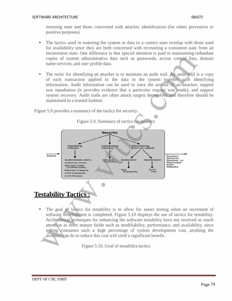
SOFTWARE ARCHITECTURE 06IS72
DEPT OF CSE, SJBIT Page 79
restoring state and those concerned with attacker identification (for either preventive orpunitive purposes).
The tactics used in restoring the system or data to a correct state overlap with those usedfor availability since they are both concerned with recovering a consistent state from aninconsistent state. One difference is that special attention is paid to maintaining redundantcopies of system administrative data such as passwords, access control lists, domainname services, and user profile data.
The tactic for identifying an attacker is to maintain an audit trail. An audit trail is a copyof each transaction applied to the data in the system together with identifyinginformation. Audit information can be used to trace the actions of an attacker, supportnon repudiation (it provides evidence that a particular request was made), and supportsystem recovery. Audit trails are often attack targets themselves and therefore should bemaintained in a trusted fashion.
Figure 5.9 provides a summary of the tactics for security.
Figure 5.9. Summary of tactics for security
Testability Tactics :
The goal of tactics for testability is to allow for easier testing when an increment ofsoftware development is completed. Figure 5.10 displays the use of tactics for testability.Architectural techniques for enhancing the software testability have not received as muchattention as more mature fields such as modifiability, performance, and availability, sincetesting consumes such a high percentage of system development cost, anything thearchitect can do to reduce this cost will yield a significant benefit.
Figure 5.10. Goal of testability tacticswww.vtuc
s.com

SOFTWARE ARCHITECTURE 06IS72
DEPT OF CSE, SJBIT Page 80
The goal of a testing regimen is to discover faults. This requires that input be provided tothe software being tested and that the output be captured.
Executing the test procedures requires some software to provide input to the softwarebeing tested and to capture the output. This is called a test harness. A question we do notconsider here is the design and generation of the test harness. In some systems, this takessubstantial time and expense.
We discuss two categories of tactics for testing: providing input and capturing output, andinternal monitoring.
INPUT/OUTPUT
There are three tactics for managing input and output for testing.
Record/playback. Record/playback refers to both capturing information crossing aninterface and using it as input into the test harness. The information crossing an interfaceduring normal operation is saved in some repository and represents output from onecomponent and input to another. Recording this information allows test input for one ofthe components to be generated and test output for later comparison to be saved.
Separate interface from implementation. Separating the interface from theimplementation allows substitution of implementations for various testing purposes.Stubbing implementations allows the remainder of the system to be tested in the absenceof the component being stubbed. Substituting a specialized component allows thecomponent being replaced to act as a test harness for the remainder of the system.
Specialize access routes/interfaces. Having specialized testing interfaces allows thecapturing or specification of variable values for a component through a testharness as well as independently from its normal execution.
For example, metadata might be made available through a specialized interface thata test harness would use to drive its activities. Specialized access routes and interfacesshould be kept separate from the access routes and interfaces for required functionality.Having a hierarchy of test interfaces in the architecture means that test cases can beapplied at any level in the architecture and that the testing functionality is in place toobserve the response.
INTERNAL MONITORING
www.vtuc
s.com

SOFTWARE ARCHITECTURE 06IS72
DEPT OF CSE, SJBIT Page 81
A component can implement tactics based on internal state to support the testing process.
Built-in monitors. The component can maintain state, performance load, capacity,security, or other information accessible through an interface. This interface can be apermanent interface of the component or it can be introduced temporarily via an
instrumentation technique such as aspect-oriented programming orpreprocessor macros.
A common technique is to record events when monitoring states have been activated.Monitoring states can actually increase the testing effort since tests may have to berepeated with the monitoring turned off. Increased visibility into the activities of thecomponent usually more than outweigh the cost of the additional testing.
Figure 5.11 provides a summary of the tactics used for testability.
Figure 5.11. Summary of testability tactics
Usability Tactics :
Usability is concerned with how easy it is for the user to accomplish a desired task and the kindof support the system provides to the user. Two types of tactics support usability, each intendedfor two categories of "users." The first category, runtime, includes those that support the userduring system execution. The second category is based on the iterative nature of user interfacedesign and supports the interface developer at design time. It is strongly related to themodifiability tactics already presented.
Figure 5.12 shows the goal of the runtime tactics.
Figure 5.12. Goal of runtime usability tacticswww.vtuc
s.com

SOFTWARE ARCHITECTURE 06IS72
DEPT OF CSE, SJBIT Page 82
RUNTIME TACTICS
Once a system is executing, usability is enhanced by giving the user feedback as to whatthe system is doing and by providing the user with the ability to issue usability-basedcommands. For example, cancel, undo, aggregate, and show multiple views support theuser in either error correction or more efficient operations.
Researchers in human computer interaction have used the terms "user initiative," "systeminitiative," and "mixed initiative" to describe which of the human computer pair takes theinitiative in performing certain actions and how the interaction proceeds. UnderstandingQuality Attributes, combine initiatives from both perspectives.
For example, when canceling a command the user issues a cancel "user initiative" and thesystem responds. During the cancel, however, the system may put up a progress indicator"system initiative." Thus, cancel demonstrates "mixed initiative." We use this distinctionbetween user and system initiative to discuss the tactics that the architect uses to achievethe various scenarios.
When the user takes the initiative, the architect designs a response as if for any otherpiece of functionality. The architect must enumerate the responsibilities of the system torespond to the user command. To use the cancel example again: When the user issues acancel command, the system must be listening for it (thus, there is the responsibility tohave a constant listener that is not blocked by the actions of whatever is being canceled);the command to cancel must be killed; any resources being used by the canceled commandmust be freed; and components that are collaborating with the canceled commandmust be informed so that they can also take appropriate action.
When the system takes the initiative, it must rely on some information, a model, about the user,the task being undertaken by the user, or the system state itself. Each model requires various typesof input to accomplish its initiative. The system initiative tactics are those that identify themodels the system uses to predict either its own behavior or the user's intention. Encapsulatingthis information will enable an architect to more easily tailor and modify those models. Tailoringand modification can be either dynamically based on past user behavior or offline duringdevelopment.
Maintain a model of the task. In this case, the model maintained is that of the task.The task model is used to determine context so the system can have some idea of whatthe user is attempting and provide various kinds of assistance. For example, knowing that
www.vtuc
s.com

SOFTWARE ARCHITECTURE 06IS72
DEPT OF CSE, SJBIT Page 83
sentences usually start with capital letters would allow an application to correct alower-case letter in that position.
Maintain a model of the user. In this case, the model maintained is of the user. Itdetermines the user's knowledge of the system, the user's behavior in terms of expectedresponse time, and other aspects specific to a user or a class of users. For example,maintaining a user model allows the system to pace scrolling so that pages do not fly pastfaster than they can be read.
Maintain a model of the system. In this case, the model maintained is that of the system.It determines the expected system behavior so that appropriate feedbackcan be given to the user. The system model predicts items such as the time needed tocomplete current activity.
DESIGN-TIME TACTICS
User interfaces are typically revised frequently during the testing process. That is, the usabilityengineer will give the developers revisions to the current user interface design and thedevelopers will implement them. This leads to a tactic that is a refinement of the modifiabilitytactic of semantic coherence:
Separate the user interface from the rest of the application. Localizing expected changesis the rationale for semantic coherence. Since the user interface is expected to changefrequently both during the development and after deployment, maintaining the userinterface code separately will localize changes to it. The software architecture patternsdeveloped to implement this tactic and to support the modification of the user interfaceare:- Model-View-Controller- Presentation-Abstraction-Control- Arch/Slinky
Figure 5.13 shows a summary of the runtime tactics to achieve usability.
Figure 5.13. Summary of runtime usability tactics
Relationship of Tactics to Architectural Patterns :The Active Object design pattern decouples method execution from method invocation to enhanceconcurrency and simplify synchronized access to objects that reside in their own thread of
www.vtuc
s.com

SOFTWARE ARCHITECTURE 06IS72
DEPT OF CSE, SJBIT Page 84
control.The motivation for this pattern is to enhance concurrency, a performance goal. Thus, its mainpurpose is to implement the "introduce concurrency" performance tactic. Notice the other tacticsthis pattern involves, however.
Information hiding (modifiability). Each element chooses the responsibilities it willachieve and hides their achievement behind an interface.
Intermediary (modifiability). The proxy acts as an intermediary that will buffer changesto the method invocation.
Binding time (modifiability). The active object pattern assumes that requests for theobject arrive at the object at runtime. The binding of the client to the proxy, however, isleft open in terms of binding time.
Scheduling policy (performance). The scheduler implements some scheduling policy.
Any pattern implements several tactics, often concerned with different quality attributes, and anyimplementation of the pattern also makes choices about tactics. For example, an implementationcould maintain a log of requests to the active object for supporting recovery, maintaining anaudit trail, or supporting testability.
The analysis process for the architect involves understanding all of the tactics embedded in animplementation, and the design process involves making a judicious choice of what combinationof tactics will achieve the system's desired goals.
Architectural Patterns and Styles :
An architectural pattern in software, also known as an architectural style, is analogous to anarchitectural style in buildings, such as Gothic or Greek Revival or Queen Anne. It consists of afew key features and rules for combining them so that architectural integrity is preserved. Anarchitectural pattern is determined by:
A set of element types (such as a data repository or a component that computes amathematical function).
A topological layout of the elements indicating their interrelation-ships. A set of semantic constraints (e.g., filters in a pipe-and-filter style are pure data
transducers. They incrementally transform their input stream into an output stream,but do not control either upstream or downstream elements).
A set of interaction mechanisms (e.g., subroutine call, event-subscriber,blackboard) that determine how the elements coordinate through the allowed topology.
These patterns occur not only regularly in system designs but in ways that sometimes prevent usfrom recognizing them, because in different disciplines the same architectural pattern may becalled different things. In response, a number of recurring architectural patterns, their properties,and their benefits have been cataloged. One such catalog is illustrated in Figure 5.14.
Figure 5.14. A small catalog of architectural patterns, organized by is-a lations
www.vtuc
s.com
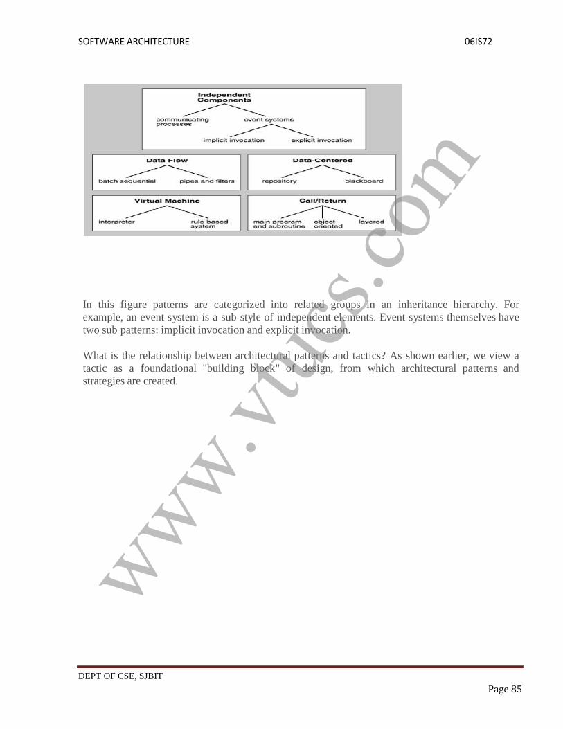
SOFTWARE ARCHITECTURE 06IS72
DEPT OF CSE, SJBIT Page 85
In this figure patterns are categorized into related groups in an inheritance hierarchy. Forexample, an event system is a sub style of independent elements. Event systems themselves havetwo sub patterns: implicit invocation and explicit invocation.
What is the relationship between architectural patterns and tactics? As shown earlier, we view atactic as a foundational "building block" of design, from which architectural patterns andstrategies are created.
www.vtuc
s.com

SOFTWARE ARCHITECTURE 06IS72
DEPT OF CSE, SJBIT Page 86
Unit 4
Contents
Architectural Patterns – 1: Introduction
From mud to structure
Layers
Pipes and Filters
Blackboard
www.vtuc
s.com

SOFTWARE ARCHITECTURE 06IS72
DEPT OF CSE, SJBIT Page 87
UNIT 4Chapter 6: ARCHITECTURAL PATTERNS-1
Introduction :
"A pattern for software architecture describes a particular recurring design problem that arisesin specific design contexts and presents a well-proven generic scheme for its solution. Thesolution scheme is specified by describing its constituent components, their responsibilities andrelationships, and the ways in which they collaborate."
In general, patterns have the following characteristics :
A pattern describes a solution to a recurring problem that arises in specific designsituations.
Patterns are not invented; they are distilled from practical experience. Patterns describe a group of components (e.g., classes or objects), how the
components interact, and the responsibilities of each component. That is, they are higherlevel abstractions than classes or objects.
Patterns provide a vocabulary for communication among designers. The choice of a namefor a pattern is very important.
Patterns help document the architectural vision of a design. If the vision is clearlyunderstood, it will less likely be violated when the system is modified.
Patterns provide a conceptual skeleton for a solution to a design problem and, hence,encourage the construction of software with well-defined properties
Typically a pattern will be described with a schema that includes at least the following threeparts :
1. Context2. Problem3. Solution
Context
The Context section describes the situation in which the design problem arises.ProblemThe Problem section describes the problem that arises repeatedly in the context.Inparticular, the description describes the set of forces repeatedly arising in the context.A force is some aspect of the problem that must be considered when attemptinga solution. Example types of forces include:
www.vtuc
s.com

SOFTWARE ARCHITECTURE 06IS72
DEPT OF CSE, SJBIT Page 88
requirements the solution must satisfy (e.g., efficiency) constraints that must be considered (e.g., use of a certain algorithm or protocol) desirable properties of a solution (e.g., easy to modify)
Forces may complementary (i.e., can be achieved simultaneously) or contradictory (i.e., canonly be balanced).SolutionThe Solution section describes a proven solution to the problem.
The solution specifies a configuration of elements to balance the forces associated with theproblem.
A pattern describes the static structure of the configuration, identifying thecomponents and the connectors (i.e., the relationships among the components).
A pattern also describes the dynamic runtime behavior of the configuration,identifying the control structure of the components and connectors.
Categories of Patterns
Patterns can be grouped into three categories according to their level of abstraction:Architectural patternsDesign patternsIdioms
Architectural patterns"An architectural pattern expresses a fundamental structural organization schema forsoftware systems. It provides a set of predefined subsystems, specifies theirresponsibilities, and includes rules and guidelines for organizing the relationshipsbetween them."
An architectural pattern is a high-level abstraction. The choice of the architectural pattern to beused is a fundamental design decision in the development of a software system. It determines thesystem-wide structure and constrains the design choices available for the various subsystems. Itis, in general, independent of the implementation language to be used.An example of an architectural pattern is the Pipes and Filters pattern. In Unix forinstance, a filter is a program that reads a stream of bytes from its standard input and writes atransformed stream to its standard output. These programs can be chained together with theoutput of one filter becoming the input of the next filter in the sequence via the pipe mechanism.Design patterns
"A design pattern provides a scheme for refining the subsystems or components of asoftware system, or the relationships between them. It describes a commonly- recurringstructure of communicating components that solves a general design problem within a
particular context."
www.vtuc
s.com

SOFTWARE ARCHITECTURE 06IS72
DEPT OF CSE, SJBIT Page 89
A design pattern is a mid-level abstraction. The choice of a design pattern does not affect thefundamental structure of the software system, but it does affect the structure of a subsystem.Like the architectural pattern, the design pattern tends to be independent of the implementationlanguage to be used.
Examples of design patterns include the following:
Adapter (or Wrapper) pattern.This pattern adapts the interface of one existing type of object to have the same interfaceas a different existing type of object.
Iterator pattern.This pattern defines mechanisms for stepping through container data structures elementby element.
Strategy (or Policy) pattern.The goal of this pattern is to allow any one of a family of related algorithms to be easilysubstituted in a system.
Idioms
"An idiom is a low-level pattern specific to a programming language. An idiomdescribes how to implement particular aspects of components or the relationshipsbetween them using the features of the given language."
An idiom is a low-level abstraction. It is usually a language-specific pattern that dealswith some aspects of both design and implementation.
In some sense, use of a consistent program coding and formatting style can be consideredan idiom for the language being used. Such a style would provide guidelines for namingvariables, laying out declarations, indenting control structures, ordering the features of aclass, determining how values are returned, and so forth. A good style that is usedconsistently makes a program easier to understand than otherwise would be the case.
Another example of an idiom is the use of the Counted Pointer (or Counted Body orReference Counting) technique for storage management of shared objects in C++. In thisidiom, we control access to a shared object through two classes, a Body (representation)class and a Handle (access) class.
An object of the Body class holds the shared object and a count of the number ofreferences to the object.
An object of a Handle class holds a direct reference to a body object; all other parts of theprogram must access the body indirectly through handle class methods. The handlemethods can increment the reference count when a new reference is created anddecrement the count when a reference is freed. When a reference count goes to zero, theshared object and its body can be deleted.
A variant of the Counted Pointer idiom can be used to implement a "copy on write"mechanism. That is, the body is shared as long as only "read" access is needed, but acopy is created whenever one of the holders makes a change to the state of the object.
www.vtuc
s.com

SOFTWARE ARCHITECTURE 06IS72
DEPT OF CSE, SJBIT Page 90
Layers :
Some design patterns, describe the implementation of micro-architectures. These designpatterns are useful, for the most part, to describe small-scale object interactions.
Other design patterns are useful for abstracting large systems of objects. These arearchitectural design patterns. An architectural pattern is any pattern concerned with theconstruction context of a whole system, rather than just some part of a system.
The distinction between micro-architectures and system architectures depends on yourpoint of view and the scale of your system. If your system has 5 objects then the micro-architecture-style design patterns are architectural patterns because they consider thestructure, relative communication, and design philosophy for the system. But morecommonly, architectural design patterns are used to describe the structure of biggersystems where the number of objects is measured in hundreds or thousands.
Layers is an architectural design pattern that structures applications so they can bedecomposed into groups of subtasks such that each group of subtasks is at a particular level ofabstraction.
Some Examples
The traditional 3-tier client server model, which separates application functionality into threedistinct abstractions, is an example of layered design..
Context
A large system requires decomposition. One way to decompose a system is to segment it intocollaborating objects. In large systems a first-cut rough model might produce hundreds orthousands of potential objects. Additional refactoring typically leads to object groupings thatprovide related types of services. When these groups are properly segmented, and their interfacesconsolidated, the result is a layered architecture.
Benefits
www.vtuc
s.com

SOFTWARE ARCHITECTURE 06IS72
DEPT OF CSE, SJBIT Page 91
-Segmentation of high-level from low-level issues. Complex problems can be broken into smallermore manageable pieces.
-Since the specification of a layer says nothing about its implementation, theimplementation details of a layer are hidden (abstracted) from other layers.
-Many upper layers can share the services of a lower layer. Thus layering allows us to reusefunctionality.
-Development by teams is aided because of the logical segmentation.
-Easier exchange of parts at a later date.
A Layered model does not imply that each layer should be in a separate address space. Efficientimplementations demand that layer-crossings be fast and cheap. Examples: User Interfaces mayneed efficient access to field validations.
Caching Layers
Layers are logical places to keep information caches. Requests that normally travel down throughseveral layers can be cached to improve performance.
Intra- and inter-Application Communications
A systems programming interface is often implemented as a layer. Thus if two applications (orinter-application elements) need to communicate, placing the interface responsibilities intodedicated layers can greatly simplify the other applications layers and, as a bonus, make themmore easily reusable.
The GUI Layer
The principle of separating the user interface from the application proper is old. It is rarelypracticed, for all the talk we devote to it. The principle of separating the user interface from theapplication has the hardest consequences and is hardest to follow consistently.
It is easier on the user if input errors are brought up directly upon entry. Having the UI outsidethe application separates input from error detection. First the UI will change, so isolate andmake an interface to it. Then someone will remove the human from the picture entirely,with electronic interchange or another application driving the program.
Therefore, just making an interface to the UI component is not sufficient, it has to be an interfacethat does not care about the UI.
Pipes and Filters :
www.vtuc
s.com

SOFTWARE ARCHITECTURE 06IS72
DEPT OF CSE, SJBIT Page 92
"The Pipes and Filters architectural pattern provides a structure for systems that process astream of data. Each processing step is encapsulated in a filter component. Data [are] passedthrough pipes between adjacent filters. Recombining filters allows you to build families ofrelated filters."
Context
The context consists of programs that must process streams of data.
Problem
Suppose we need to build a system to solve a problem:
that must be built by several developers
that decomposes naturally into several independent processing steps for
which the requirements are likely to change.
Structure
The filters are the processing units of the pipeline. A filter may enrich, refine, ortransform its input data
It may enrich the data by computing new information from the input data and addingit to the output data stream.
It may refine the data by concentrating or extracting information from the input datastream and passing only that information to the output stream.
It may transform the input data to a new form before passing it to the output stream. It may, of course, do some combination of enrichment, refinement, and
transformation.
A filter may be active (the more common case) or passive.
An active filter runs as a separate process or thread; it actively pulls data from the inputdata stream and pushes the transformed data onto the output data stream.
A passive filter is activated by either being called:
as a function, a pull of the output from the filter
as a procedure, a push of output data into the filter
www.vtuc
s.com

SOFTWARE ARCHITECTURE 06IS72
DEPT OF CSE, SJBIT Page 93
The pipes are the connectors--between a data source and the first filter, between filters, andbetween the last filter and a data sink. As needed, a pipe synchronizes the active elements that itconnects together.
A data source is an entity (e.g., a file or input device) that provides the input data to the system.It may either actively push data down the pipeline or passively supply data when requested,depending upon the situation.
A data sink is an entity that gathers data at the end of a pipeline. It may either actively pull datafrom the last filter element or it may passively respond when requested by the last filter element.
Implementation
Implementation of the pipes-and-filters architecture is usually not difficult. It often includesthe following steps:
1. Divide the functionality of the problem into a sequence of processing steps.Each step should only depend upon the outputs of the previous step in thesequence. The steps will become the filters in the system.
In dividing up the functionality, be sure to consider variations or later changes thatmight be needed--a reordering of the steps or substitution of one processing step foranother.
2. Define the type and format of the data to be passed along each pipe.For example, Unix pipes carry an unstructured sequence of bytes. However, many Unixfilters read and write streams of ASCII characters that are structured into lines (with thenewline character as the line terminator).
Another important formatting issue is how the end of the input is marked. A filter mightrely upon a system end-of-input condition or it may need to implement their own"sentinel" data value to mark the end.
3. Determine how to implement each pipe connection.For example, a pipe connecting active filters might be implemented with operatingsystem or programming language runtime facility such as a message queue, a Unix-stylepipe, or a synchronized-access bounded buffer.
A pipe connecting to a passive filter might be implemented as a direct call of theadjacent filter: a push connection as a call of the downstream filter as a procedure or apull connection as a call of the upstream filter as a function.
4. Design and implement the filters.The design of a filter is based on the nature of the task to be performed and the natures ofthe pipes to which it can be connected.
www.vtuc
s.com

SOFTWARE ARCHITECTURE 06IS72
DEPT OF CSE, SJBIT Page 94
o An active filter needs to run with its own thread of control. It might run as as a"heavyweight" operating system process (i.e., having its own address space)or as a "lightweight" thread (i.e., sharing an address space with other threads).
o A passive filter does not require a separate thread of control (although it couldbe implemented with a separate thread).
The selection of the size of the buffer inside a pipe is an important performance tradeoff.Large buffers may use up much available memory but likely will involve lesssynchronization and context-switching overhead. Small buffers conserve memory atthe cost of increased overhead.
To make filters flexible and, hence, increase their potential reusability, they often willneed different processing options that can be set when they are initiated. For example,Unix filters often take command line parameters, access environment variables, or readinitialization files.
5. Design for robust handling of errors.
Error handling is difficult in a pipes-and-filters system since there is no global state andoften multiple asynchronous threads of execution. At the least, a pipes- and-filters systemneeds mechanisms for detecting and reporting errors. An error should not result inincorrect output or other damage to the data.
For example, a Unix program can use the stderr channel to report errors to itsenvironment.
More sophisticated pipes-and-filters systems should seek to recover from errors. Forexample, the system might discard bad input and resynchronize at some well- definedpoint later in the input data. Alternatively, the system might back up the input to somewell-defined point and restart the processing, perhaps using a different processing methodfor the bad data.
6. Configure the pipes-and-filters system and initiate the processing.
One approach is to use a standardized main program to create, connect, and initiatethe needed pipe and filter elements of the pipeline.
Another approach is to use an end-user tool, such as a command shell or a visual pipelineeditor, to create, connect, and initiate the needed pipe and filter elements of the pipeline.
Example
An example pipes-and-filter system might be a retargetable compiler for a programminglanguage. The system might consist of a pipeline of processing elements similar to the following:
www.vtuc
s.com

SOFTWARE ARCHITECTURE 06IS72
DEPT OF CSE, SJBIT Page 95
A source element reads the program text (i.e., source code) from a file (or perhaps asequence of files) as a stream of characters.
A lexical analyzer converts the stream of characters into a stream of lexical tokens for thelanguage--keywords, identifier symbols, operator symbols, etc.
A parser recognizes a sequence of tokens that conforms to the language grammar andtranslates the sequence to an abstract syntax tree.
A "semantic" analyzer reads the abstract syntax tree and writes an appropriately augmentedabstract syntax tree.
A global optimizer (usually optionally invoked) reads an augmented syntax tree and outputsone that is equivalent but corresponds to program that is more efficient in space and timeresource usage.
An intermediate code generator translates the augmented syntax tree to a sequence ofinstructions for a virtual machine.
A local optimizer converts the sequence of intermediate code (i.e., virtual machine)instructions into a more efficient sequence.
Note: A local optimizer may transform the program by removing unneeded loads andstores of data.
A backend code generator translates the sequence of virtual machine instructions into asequence of instructions for some real machine platform (i.e., for some particularhardware processor augmented by operating system calls and a runtime library).
If the previous step generated symbolic assembly code, then an assembler is needed totranslate the sequence of symbolic instructions into a relocatable binary module.
If the previous steps of the pipeline generated a sequence of separate binary modules, then alinker might be needed to bind the separate modules with library modules to form asingle executable (i.e., object code) module.
A sink element outputs the resulting binary module into a file.
The pipeline can be reconfigured to support a number of different variations:
If source code preprocessing is to be supported (e.g., as in C), then a reprocessor filter(or filters) can be inserted in front of the lexical analyzer.
If the language is to be interpreted rather than translated into object code, then the backendcode generator (and all components after it in the pipeline) can be replaced by an
www.vtuc
s.com

SOFTWARE ARCHITECTURE 06IS72
DEPT OF CSE, SJBIT Page 96
interpreter that implements the virtual machine.
If the compiler is to be retargeted to a different platform, then a backend code generator(and assembler and linker) for the new platform can be substituted for the old one.
If the compiler is to be modified to support a different language with the same lexicalstructure, then only the parser, semantic analyzer, global optimizer, and intermediate codegenerator need to be replaced.
o Note: If the parser is driven by tables that describe the grammar, then it may bepossible to use the same parser with a different table.
If a load-and-go compiler is desired, the file-output sink can be replaced by a loader thatloads the executable module into an address space in the computer's main memory andstarts the module executing.
Blackboard :
The Blackboard pattern is useful for problems for which no deterministic solutionstrategies are known. In Blackboard several specialized subsystems assemble theirknowledge to build a possibly partial or approximate solution.
This pattern is useful for problems for which no deterministic solution strategies areknown. In Blackboard several specialised sub-systems assemble their knowledge to build apossibly partial or approximate solution.
A blackboard system is an artificial intelligence application based on the blackboardarchitectural model, where a common knowledge base, the "blackboard", is iterativelyupdated by a diverse group of specialist knowledge sources, starting with a problemspecification and ending with a solution.
Each knowledge source updates the blackboard with a partial solution when its internalconstraints match the blackboard state. In this way, the specialists work together to solvethe problem. The blackboard model was originally designed as a way to handle complex,ill-defined problems, where the solution is the sum of its parts.
A blackboard-system application consists of three major components The software specialist modules, which are called knowledge sources (KSs). Like the
human experts at a blackboard, each knowledge source provides specific expertise neededby the application. The ability to support interaction and cooperation among diverse KSscreates enormous flexibility in designing and maintaining applications. As the pace oftechnology has intensified, it becomes ever more important to be able to replace softwaremodules as they become outmoded or obsolete.
The blackboard, a shared repository of problems, partial solutions, suggestions, and
www.vtuc
s.com

SOFTWARE ARCHITECTURE 06IS72
DEPT OF CSE, SJBIT Page 97
contributed information. The blackboard can be thought of as a dynamic "library" ofcontributions to the current problem that have been recently "published" by otherknowledge sources.
Unit 5
Contents
Architectural Patterns – 2 Distributed Systems: Broker Interactive Systems MVC Presentation-Abstraction-Control
UNIT 5Chapter 7: Architectural Patterns-2
Distributed Systems :
Distributed systems architecture has rapidly evolved by applying and combining differentarchitecture patterns and styles. In recent years, decoupling interfaces andimplementation, scalable hosting models, and service orientation were the prominent tenets ofbuilding distributed systems. Distributed systems have grown from independent enterpriseapplications to Internet-connected networks of managed services, hosted on- premise and/orclouds.
Creating successful distributed systems requires that you address how that system is designed,developed, maintained, supported, and governed. Microsoft’s Service Oriented ArchitectureMaturity Model (SOAMM) assessment method helps customers assess maturity elements andprioritize the evolution of their enterprise architecture. Organizations are applying methods,patterns, and technologies to model systems and enable proper governance.
Building distributed systems involves three core capabilities, based on the following roles:Implementation of applications/services.
Consumption of services from within and external to organizations.
www.vtuc
s.com

SOFTWARE ARCHITECTURE 06IS72
DEPT OF CSE, SJBIT Page 98
Administration of services or composite services.
Broker :
The Broker pattern can be used to structure distributed software systems with decoupledcomponents that interact by remote service invocations. A broker component is responsible forcoordinating communication, such as forwarding requests, as well as for transmitting results andexceptions.
The Broker pattern has many of the benefits and liabilities of the Layered Application pattern.
BenefitBroker provides the following benefits:1) Isolation. Separating all the communication-related code into its own layer isolates it fromthe application. You can decide to run the application distributed or all on one computer withouthaving to change any application code.
2) Simplicity. Encapsulating complex communication logic into a separate layer breaks downthe problem space. The engineers coding the broker do not have to concern themselveswith arcane user requirements and business logic, and the application developers do not have toconcern themselves with multicast protocols and TCP/IP routing.
3) Flexibility.
Encapsulating functions in a layer allows you to swap this layer with a differentimplementation. For example, you can switch from DCOM to .NET remoting to standardWeb services without affecting the application code.
Unfortunately, layers of abstraction can harm performance. The basic rule is that themore information you have, the better you can optimize. Using a separate broker layermay hide details about how the application uses the lower layer, which may in turnprevent the lower layer from performing specific optimizations.
For example, when you use TCP/IP, the routing protocol has no idea what is being routed.Therefore, it is hard to decide that a packet containing a video stream, for instance, shouldhave routing priority over a packet containing a junk e-mail.
The Broker architectural pattern can be used to structure distributed software systemswith decoupled components that interact by remote service invocations
Structure
There are six types of components in Broker architectural pattern:
Clients, Servers, Brokers, Bridges, Client-side proxies and Server-side proxies
www.vtuc
s.com

SOFTWARE ARCHITECTURE 06IS72
DEPT OF CSE, SJBIT Page 99
A server implements objects that expose their functionality through interfaces that consistof operations and attributes
These interfaces are either through Interface Definition Language (IDL), through a binarystandard, or some kind of APIs.
Interfaces are grouped by semantically-related functionality. So,we Would have
Servers implementing specific functionality for a single application domain or task
A broker is a messager that is responsible for the transmission of requests from clients toservers
It also takes care the transmission of responses and exceptions back to the client
A broker will store control information for locating the receivers (servers) of the requests (it is normally down with some unique system identifier, IP address might not be enough)
Broker also offer interface for clients and servers
They are usually in the form of APIs with control operations such as registering serversand invoking server methods
Broker keeps track of all the servers information it maintains locally. If a request comesin and it is for a server that is on the tracking list. It passes the request along directly
If the server is currently inactive, the broker activates it (spawn a job, folk a process,create a thread, use a pre start job, etc)
Then response are passed back to the client through the broker
If the request is for a server hosted by another broker, the local broker finds a route to theremote broker and forwards the request using this route (So, a common way ofcommunication among brokers is needed)
It hides the implementation detail such as:Inter-process communication mechanism used for message transfer between clients
and brokersThe creation and deletion of memory blocks (remember, we are dealing with
multiple different languages to build a system, not just Java)The marshaling of parameters and results
In most cases, client-side proxies translate the object model specified as part of the Brokerarchitectural pattern to the object model of the programming language used to implement the
www.vtuc
s.com

SOFTWARE ARCHITECTURE 06IS72
DEPT OF CSE, SJBIT Page 100
client
Advantages
Location TransparencyChangeability and extensibility of componentsPortability of a Broker system
Interoperability between different Broker systemsReusabilityTesting and Dubugging
MVC :
Model–View–Controller (MVC) is a software architecture currently considered anarchitectural pattern used in software engineering. The pattern isolates "domain logic" (theapplication logic for the user) from input and presentation (GUI), permitting independentdevelopment, testing and maintenance of each.
The Model-View-Controller pattern (MVC) divides an interactive application into threecomponents. The model contains the core functionality and data. Views display information tothe user. Controllers handle user input. Views and controllers together comprise the userinterface. A change-propagation mechanism ensures consistency between the user interface andthe model.
The model is used to manage information and notify observers when that information changes.The model is the domain-specific representation of the data upon which the application operates.Domain logic adds meaning to raw data (for example, calculating whether today is the user'sbirthday, or the totals, taxes, and shipping charges for shopping cart items). When a modelchanges its state, it notifies its associated views so they can be refreshed.
The controller receives input and initiates a response by making calls on model objects. Acontroller accepts input from the user and instructs the model and viewport to perform actionsbased on that input.
An MVC application may be a collection of model/view/controller triplets, each responsible fora different UI element.
MVC is often seen in web applications where the view is the HTML or XHTMLgenerated by the app. The controller receives GET or POST input and decides what to do with it,handing over to domain objects (i.e. the model) that contain the business rules and know how tocarry out specific tasks such as processing a new subscription.
Though MVC comes in different flavors, control flow is generally as follows:
www.vtuc
s.com

SOFTWARE ARCHITECTURE 06IS72
DEPT OF CSE, SJBIT Page 101
The user interacts with the user interface in some way (for example, presses a mouse button).The controller handles the input event from the user interface, often via a registered handler
or callback and converts the event into appropriate user action, understandable for themodel.
The controller notifies the model of the user action, possibly resulting in a change in themodel's state. (For example, the controller updates the user's shopping cart.)
A view queries the model in order to generate an appropriate user interface (for example, theview lists the shopping cart's contents). The view gets its own data from the model. Thecontroller may (in some implementations) issue a general instruction to the view to renderitself. In others, the view is automatically notified by the model of changes in state(Observer) which require a screen update.
The user interface waits for further user interactions, which restarts the cycle.
Some implementations such as the W3C XForms also use the concept of a dependency graph toautomate the updating of views when data in the model changes.
The goal of MVC is, by decoupling models and views, to reduce the complexity in architecturaldesign and to increase flexibility and maintainability of code.
Presentation-Abstraction-Control :
Presentation-abstraction-control (PAC) is a software architectural pattern, somewhat similarto model-view-controller (MVC). PAC is used as a hierarchical structure of agents, eachconsisting of a triad of presentation, abstraction and control parts. The agents (or triads)communicate with each other only through the control part of each triad. It also differs from MVCin that within each triad, it completely insulates the presentation (view in MVC) and theabstraction (model in MVC), this provides the option to separately multithread the model andview which can give the user experience of very short program start times, as the user interface(presentation) can be shown before the abstraction has fully initialized.
The Presentation-Abstraction-Control
pattern (PAC) defines a structure for interactive software systems in the form of ahierarchy of cooperating agents. Every agent is responsible for a specific aspect of theapplication's functionality and consists of three components: presentation, abstraction, andcontrol. This subdivision separates the hum an- computer interaction aspects of the agentfrom its functional core and its communication with other agents.
Presentation-abstraction-control (PAC) is a software architectural pattern that uses astructure for interactive software systems in the form of a hierarchy of cooperatingagents. Each of the agent consist of a triad of presentation, abstraction and controlcomponents and is responsible for a specific aspect of the application's functionality.
The agents in their triads communicate with one other through the control part of eachtriad insulating the presentation and abstraction. This insulation facilitates the
www.vtuc
s.com

SOFTWARE ARCHITECTURE 06IS72
DEPT OF CSE, SJBIT Page 102
multithreading where the presentation as the user interface can be shown before theabstraction has fully initialized. This is unlike other software architecture known asModel-View-Controller (MVC) which is restricted to simple GUI's with one or moreviews on the same model.
The Control in the PAC is similar to the Controller in the MVC architecture to someextent. The PAC architecture does not have the model as its core component. Like theMVC the Abstraction contains the data in the PAC.
Unit 6
Contents
Architectural Patterns – 3 Adaptable Systems: Microkernel Reflection
Chapter 8: Architectural Patterns-3
Adaptive systems :
Cause and Effect
For many years scientists saw the universe as a linear place. One where simple rules ofcause and effect apply. They viewed the universe as big machine and thought that if theytook the machine apart and understood the parts, then they would understand the whole.
They also thought that the universe's components could be viewed as machines, believingthat if we worked on the parts of these machines and made each part work better, then thewhole would work better. Scientists believed the universe and everything in it could bepredicted and controlled.
Complexity Theory
Gradually as scientists of all disciplines explored these phenomena a new theory emergedcomplexity theory, A theory based on relationships, emergence, patterns and iterations. Atheory that maintains that the universe is full of systems, weather systems, immune
www.vtuc
s.com

SOFTWARE ARCHITECTURE 06IS72
DEPT OF CSE, SJBIT Page 103
systems, social systems etc and that these systems are complex and constantly adapting totheir environment. Hence complex adaptive systems.
The agents in the system are all the components of that system. For example the air andwater molecules in a weather system, and flora and fauna in an ecosystem. These agentsinteract and connect with each other in unpredictable and unplanned ways.
But from this mass of interactions regularities emerge and start to form a pattern whichfeeds back on the system and informs the interactions of the agents. For example in anecosystem if a virus starts to deplete one species this results in a greater or lesser foodsupply for others in the system which affects their behaviour and their numbers. A periodof flux occurs in all the populations in the system until a new balance is established.
Properties
Complex adaptive systems have many properties and the most important are,
· Emergence: Rather than being planned or controlled the agents in the system interact inapparently random ways. From all these interactions patterns emerge which informs thebehaviour of the agents within the system and the behaviour of the system itself. For example atermite hill is a wondrous piece of architecture with a maze of interconnecting passages, largecaverns, ventilation tunnels and much more. Yet there is no grand plan, the hill just emergesas a result of the termites following a few simple local rules.
· Co-evolution: All systems exist within their own environment and they are also part of thatenvironment. Therefore, as their environment changes they need to change to ensure best fit. Butbecause they are part of their environment, when they change, they change their environment,and as it has changed they need to change again, and so it goes on as a constant process. (Perhaps it should have been Darwin's "Theory of Co-evolution". )
Some people draw a distinction between complex adaptive systems and complex evolvingsystems. Where the former continuously adapt to the changes around them but do not learn fromthe process. And where the latter learn and evolve from each change enabling them to influencetheir environment, better predict likely changes in the future..
· Requisite Variety: The greater the variety within the system the stronger it is. In fact ambiguityand paradox abound in complex adaptive systems which use contradictions to create newpossibilities to co-evolve with their environment. Democracy is a good example in that itsstrength is derived from its tolerance and even insistence in a variety..
· Connectivity: The ways in which the agents in a system connect and relate to one anotheris critical to the survival of the system, because it is from these connections that the patterns areformed and the feedback disseminated. The relationships between the agents aregenerally moreimportant than the agents themselves.
· Simple Rules: Complex adaptive systems are not complicated. The emerging patterns may have
www.vtuc
s.com

SOFTWARE ARCHITECTURE 06IS72
DEPT OF CSE, SJBIT Page 104
a rich variety, but like a kaleidoscope the rules governing the function of the system are quitesimple. A classic example is that all the water systems in the world, all the streams, rivers, lakes,oceans, waterfalls etc with their infinite beauty, power and variety are governed by thesimple principle that water finds its own level.
· Iteration: Small changes in the initial conditions of the system can have significant effects afterthey have passed through the emergence - feedback loop a few times (often referred to as thebutterfly effect). A rolling snowball for example gains on each roll much more snow than itdid on the previous roll and very soon a fist sized snowball .
· Self Organizing: There is no hierarchy of command and control in a complex adaptive system.There is no planning or managing, but there is a constant re-organizing to find the best fitwith the environment. A classic example is that if one were to take any western town andadd up all the food in the shops and divide by the number of people in the town there will benear enough two weeks supply of food, but there is no food plan, food manager or any otherformal controlling process. The system is continually self organizing through the process ofemergence and feedback.
· Edge of Chaos: Complexity theory is not the same as chaos theory, which is derived frommathematics. But chaos does have a place in complexity theory in that systems exist on aspectrum ranging from equilibrium to chaos. A system in equilibrium does not have the internaldynamics to enable it to respond to its environment and will slowly (or quickly) die. A system inchaos ceases to function as a system. The most productive state to be in is at the edge of chaoswhere there is maximum variety and creativity, leading to new possibilities.
Complex adaptive: systems are all around us. Most things we take for granted arecomplex adaptive systems, and the agents in every system exist and behave in total ignorance ofthe concept but that does not impede their contribution to the system. Complex AdaptiveSystems are a model for thinking about the world around us not a model for predicting whatwill happen.
Microkernel :
The Microkernel pattern applies to software systems that must be able to adapt to changingsystem requirements. It separates a minimal functional core from extended functionality andcustomer-specific parts. The microkernel also serves as a socket for plugging in these extensionsand coordinating their collaboration.
Context and Problem
The pattern may be applied in the context of complex software systems serving as a platform forother software applications. Such complex systems usually should be extensible and adaptable toemerging technologies, capable of coping with a range of standards and technologies. They alsoneed to possess high performance and scalability qualities; as a result, low memory consumptionand low processing demands are required. Taken together, the above requirements are difficult to
www.vtuc
s.com

SOFTWARE ARCHITECTURE 06IS72
DEPT OF CSE, SJBIT Page 105
achieve.
Solution, Consequences and Liabilities
- The most important core services of the system should be encapsulated in a microkernelcomponent. The microkernel maintains the system resources and allows othercomponents to interact with each other as well as to access the functionality of themicrokernel. It encapsulates a significant part of system-specific dependencies, such ashardware-dependent aspects. The size of the microkernel should be kept to a minimum,therefore, only part of the core functionality can be included in it; the rest of the corefunctionality is deferred to separate internal servers.
- Internal servers extend the functionalities of the microkernel. Internal servers can forexample handle graphics and storage media. Internal servers can have their ownprocesses or they can be shared Dynamic Link Libraries (DLL) loaded inside the kernel. Theexternal server provides a more complex functionality; they are built on top of the coreservices provided by the microkernel.
- Different external servers may be needed in the system in order to provide the functionalityfor specific application domains. These servers run in separate processes and employ thecommunication facilities provided by microkernel to receiverequests from their clientsand to return the results. The role of the adapter is to provide a transparent interface forclients to communicate with external servers. Adapter hides the system dependencies such ascommunication facilities from the client. Adapter thus improves the scalability andchangeability of the system. The adapter enables the servers and clients to be distributed overa network.
The benefits of the pattern can be mentioned like:
Good portability, since only microkernel need to be modified when porting the systemto a new environment.
High flexibility and extensibility, as modifications or extensions can be done by modifyingor extending internal servers.
Separation of low-level mechanisms (provided by microkernel and internal servers) andhigher-level policies (provided by external servers) improves maintainability andchangeability of the system.
There are some concerns about it as well.
1. The microkernel system requires much more inter-process communication inside oneapplication execution because of the calls to internal and external servers.
2. The design and implementation of the microkernel -based system is far more complexthan of a monolithic system
www.vtuc
s.com

SOFTWARE ARCHITECTURE 06IS72
DEPT OF CSE, SJBIT Page 106
Reflection :
- The Reflection pattern provides a mechanism for changing structure and behavior of softwaresystems dynamically. It supports the modification of fundamental aspects, such as typestructures and function call mechanisms. In this pattern, an application is split into two parts.A meta level provides information about selected system properties and makes the softwareself-aware. A base level includes the application logic. Its implementation builds on the metalevel. Changes to information kept in the meta level affect subsequent base-level behavior.
- The Reflection pattern provides a mechanism for changing structure and behavior ofsoftware systems dynamically. It supports the modification of fundamental aspects, such astype structures and function call mechanisms. In this pattern, an application is split into twoparts. A meta level provides information about selected system properties and makes thesoftware self-aware. A base level includes the application logic. Its implementation builds onthe meta level. Changes to information kept in the meta level affect subsequent base-levelbehavior.
- The Reflective Blackboard architectural pattern is independent of programminglanguages and specific implementation frameworks, and its use can minimize the complexitycaused by the presence of numerous system-level properties in MASs.
Structure
- The controller subsystem is composed of a meta-object protocol (MOP) component thattogether with a collection of meta-objects implement the multi-agent system controlstrategies. Meta-objects are composed of data (metadata) and are responsible for associatingspecific behavior (reactions) to operations performed over specific pieces of data.
These meta-objects can transparently modify the normal behavior of the blackboard, thusimplementing the multi-agent system control strategies. Different agents can act over theblackboard by means of their sensors and effectuators, which can respectively sense andperform changes in the blackboard that can be considered their environment. The agents do notcommunicate directly; they only write and read data from the blackboard.
- Whenever an agent performs any operation over a specific piece of data stored atblackboard, the MOP component verifies if there is any meta-object associated to it. Ifpositive it executes the reaction associated to the meta-object, i.e. its behavior.The meta-object execution can access the blackboard writing and deleting data.
- In this way, in a reflective blackboard architecture the semantics of a blackboard operation,in fact, is the result of the execution of the meta-objects associated to it. Meta-objects alsomay exist in the control subsystem without correspondent data in the blackboard. In thisway the multi-agent system can associate reactions to data that is part of the multi-agentsystem vocabulary and probably will be written in the blackboard at runtime.
www.vtuc
s.com

SOFTWARE ARCHITECTURE 06IS72
DEPT OF CSE, SJBIT Page 107
Reflection is used to intercept and modify the effects of operations of the blackboard.
From the point of view of application agents, computational reflection is transparent: an agentwrites a piece of data on the blackboard, and has no knowledge this write operation has beenintercepted and redirected to the meta-level. The following scenario illustrates the general behaviorof the Reflective Blackboard architecture:
1. A knowledge source (or agent) performs an operation on the blackboard (write forexample), supplying a piece of data and expecting some other piece of retrieved data;2. This operation is intercepted by the meta-level’s MOP, which will perform, ifspecified, control activities over the performed operation;3. The MOP checks for the existence of meta-objects associated to the blackboard data andrelated to the performed operation. If the knowledge source has performed a write operation onthe blackboard, the searched meta-objects will be those related to the written piece of data. Onthe other hand, if the knowledge source has performed read or delete operations, the searchedmeta-object will be related to the piece of data read from the blackboard;
UNIT-7Contents
Some Design Patterns
Structural decomposition
Whole – Part
Organization of work: Master – Slave
Access Control
Proxy
www.vtuc
s.com

SOFTWARE ARCHITECTURE 06IS72
DEPT OF CSE, SJBIT Page 108
UNIT-7Chapter 9: SOME DESIGN PATTERNS
Structural Decomposition :
Design patterns systematically names, explains and evaluates an important and recurring designin object-oriented systems. Their main objective is to reuse successful designs and architecturesof experienced and professional designers. Structural design patterns relate to class and objectcomposition. They use inheritance to compose interfaces and define ways to compose objects toobtain new functionality.
The design patterns in this group further emphasize and clarify the fundamental differencesbetween the UML and OPM design pattern models:
whole-Part :
In this there will be two parts. The structure of whole and part are shown below :
Class: Whole
Responsibility:
Aggregates several smaller objects Provides services built on top of part objects Acts as a wrapper around its constituent parts
Collaborators: Partwww.vtuc
s.com

SOFTWARE ARCHITECTURE 06IS72
DEPT OF CSE, SJBIT Page 109
Class: Part
Responsibility: Represents a particular object and its services
Collaborators: - Nil
Whole object: It is an aggregation of smaller objects
The smaller objects are called Parts
Whole object forms a semantic grouping of its Parts in that it coordinates andorganizes their collaboration
The Whole uses the functionality of Parts objects for implementing services
Implementation
1. Design the public Interface of the Whole2. Separate the Whole into Parts, or make it from existing ones (Use either bottom- up, top-
down or both mixed)3. Use existing Parts from component libraries or class libraries or package, specify their
collaboration if you use bottom-up approach4. Partition the Whole's services into smaller collaborating services and map these
collaborating services to separate Parts if you follow a top-down approach5. Specific the services of the Whole in terms of services of the Parts6. Implement the Parts (Recursively if Parts are not leaf)7. Implement the Whole by putting all the Parts together
Advantages
Changeability of Parts
Reusability
Defines class hierarchies consisting of primitive objects
Makes the client simple
Makes it easier to add new kinds of components
Disadvantageswww.vtuc
s.com

SOFTWARE ARCHITECTURE 06IS72
DEPT OF CSE, SJBIT Page 110
1) Makes your design overly general2) Lower efficiency through indirection3) Complexity of decomposition into Parts might be an art
Organization of work : Master-Slave :
The Master-Slave design pattern supports fault tolerance, parallel computation andcomputational accuracy. A master component distributes work to identical slavecomponents and computes a final result from the results these slaves return.
It is used when you have two or more processes that need to run simultaneously andcontinuously but at different rates. If these processes run in a single loop, severe timingissues can occur. These timing issues occur when one part of the loop takes longer toexecute than expected. If this happens, the remaining sections in the loop get delayed.
The Master/Slave pattern consists of multiple parallel loops. Each of the loops mayexecute tasks at different rates. Of these parallel loops, one loop acts as the master andthe others act as slaves. The master loop controls all of the slave loops, andcommunicates with them using messaging architectures.
It acquires a waveform from a transmission line and displays it on a graph every 100ms,and also provides a user interface that allows the user to change parameters for eachacquisition. The Master/Slave design pattern is well suited for this application. In thisapplication, the master loop will contain the user interface. The voltage acquisition andlogging will happen in one slave loop, while the transmission line acquisition andgraphing will.
This situation can be avoided by applying the Master/Slave design pattern to theapplication. In this case, the user interface will be handled by the master loop, and everycontrollable section of the robotic arm will have its own slave loop. Using this method,each controllable section of the arm will have its own loop, and therefore, its own piece ofprocessing time.
The Master/Slave design pattern is very advantageous when creating multi-taskapplications. It gives you a more modular approach to application development becauseof its multi-loop functionality, but most importantly, it gives you more control of yourapplication’s time management.
The Master/Slave design pattern consists of multiple parallel loops. The loop that controlsall the others is the master and the remaining loops are slaves. One master loop
always drives one or more slave loops. Since data communication directly between these loopsbreaks data flow, it must be done by writing and reading to messaging architectureswww.vt
ucs.c
om

SOFTWARE ARCHITECTURE 06IS72
DEPT OF CSE, SJBIT Page 111
An access control model describes at a high level of abstraction a mechanism forgoverning access to shared resources.
UNIT 8Contents
Architecture in the life cycle
designing the architecture
Forming the team structure
Creating a skeletal system
Uses of architectural documentation
Views
choosing the relevant views
Documenting a view
Documentation across views
Chapter 10 : Designing and documenting softwareArchitecture
Architecture in the Life Cycle :
Any organization that embraces architecture as a foundation for its software developmentprocesses needs to understand its place in the life cycle. Several life-cycle models exist in theliterature, but one that puts architecture squarely in the middle of things is the EvolutionaryDelivery Life Cycle model shown in Figure 7.1. The intent of this model is to get user andcustomer feedback and iterate through several releases before the final release. The model alsoallows the adding of functionality with each iteration and the delivery of a limited version once asufficient set of features has been developed.www.vt
ucs.c
om

SOFTWARE ARCHITECTURE 06IS72
DEPT OF CSE, SJBIT Page 112
Figure 7.1. Evolutionary Delivery Life Cycle
The life-cycle model shows the design of the architecture as iterating with preliminaryrequirements analysis. Clearly, one cannot begin the design until he has some idea of the systemrequirements. On the other hand, it does not take many requirements in order for design to begin.
Once the architectural drivers are known, the architectural design can begin. The requirementsanalysis process will then be influenced by the questions generated during architectural designone of the reverse-direction arrows shown in Figure 7.1.
Designing the Architecture :
There is a method for designing an architecture to satisfy both quality requirements andfunctional requirements. This method is known as Attribute-Driven Design (ADD). ADD takesas input a set of quality attribute scenarios and employs knowledge about the relationbetween quality attribute achievement and architecture in order to design the architecture.
The ADD method can be viewed as an extension to most other development methods, such as theRational Unified Process. The Rational Unified Process has several steps that result in the high-level design of an architecture but then proceeds to detailed design and implementation.Incorporating ADD into it involves modifying the steps dealing with the high-level design of thearchitecture and then following the process as described by Rational.www.vt
ucs.c
om

SOFTWARE ARCHITECTURE 06IS72
DEPT OF CSE, SJBIT Page 113
ATTRIBUTE-DRIVEN DESIGN
ADD is an approach to defining a software architecture that bases the decompositionprocess on the quality attributes the software has to fulfill. It is a recursive decompositionprocess where, at each stage, tactics and architectural patterns are chosen to satisfy a setof quality scenarios and then functionality is allocated to instantiate the module typesprovided by the pattern. ADD is positioned in the life cycle after requirements analysisand, as we have said, can begin when the architectural drivers are known with someconfidence.
The output of ADD is the first several levels of a module decomposition view of anarchitecture and other views as appropriate. Not all details of the views result from anapplication of ADD; the system is described as a set of containers for functionality andthe interactions among them. This is the first articulation of architecture during the designprocess and is therefore necessarily coarse grained.
Nevertheless, it is critical for achieving the desired qualities, and it provides a frameworkfor achieving the functionality. The difference between an architecture resulting fromADD and one ready for implementation rests in the more detailed design decisions thatneed to be made. These could be, for example, the decision to use specific object-oriented design patterns or a specific piece of middleware that brings with it manyarchitectural constraints. The architecture designed by ADD may have intentionallydeferred this decision to be more flexible.
ADD Steps
Following are the steps performed when designing an architecture using the ADDmethod.
1. Choose the module to decompose. The module to start with is usually the whole system.All required inputs for this module should be available (constraints, functionalrequirements, quality requirements).
2. Refine the module according to these steps:a. Choose the architectural drivers from the set of concrete quality scenarios and
functional requirements. This step determines what is important for thisdecomposition.
b. Choose an architectural pattern that satisfies the architectural drivers.Create (or select) the pattern based on the tactics that can be used to achieve thedrivers. Identify child modules required to implement the tactics.
c. Instantiate modules and allocate functionality from the use cases andrepresent using multiple views.
d. Define interfaces of the child modules. The decomposition provides modulesand constraints on the types of module interactions. Document this information inwww.vt
ucs.c
om

SOFTWARE ARCHITECTURE 06IS72
DEPT OF CSE, SJBIT Page 114
the interface document for each module.e. Verify and refine use cases and quality scenarios and make them
constraints for the child modules. This step verifies that nothing important wasforgotten and prepares the child modules for further decomposition orimplementation.
3. Repeat the steps above for every module that needs further decomposition.
Figure 7.2. Architectural pattern that utilizes tactics to achieve garage door drivers
Instantiate modules
In Figure 7.2, it identifies a non-performance-critical computation running on top of a virtualmachine that manages communication and sensor interactions. The software running on topof the virtual machine is typically an application. In a concrete system we will normally havemore than one module. There will be one for each "group" of functionality; these will beinstances of the types shown in the pattern. Our criterion for allocating functionality is similar tothat used in functionality-based design methods, such as most object-oriented design methods.
Figure 7.3. First-level decomposition of garage door opener
www.vtuc
s.com

SOFTWARE ARCHITECTURE 06IS72
DEPT OF CSE, SJBIT Page 115
The result of this step is a plausible decomposition of a module. The next steps verify howwell the decomposition achieves the required functionality.
Allocate functionality
Applying use cases that pertain to the parent module helps the architect gain a moredetailed understanding of the distribution of functionality. This also may lead to addingor removing child modules to fulfill all the functionality required. At the end, every usecase of the parent module must be representable by a sequence of responsibilities withinthe child modules.
Assigning responsibilities to the children in a decomposition also leads to the discoveryof necessary information exchange. This creates a producer/consumer relationshipbetween those modules, which needs to be recorded. At this point in the design, it is notimportant to define how the information is exchanged.
Is the information pushed or pulled? Is it passed as a message or a call parameter? Theseare all questions that need to be answered later in the design process. At this point only theinformation itself and the producer and consumer roles are of interest. This is an example ofthe type of information left unresolved by ADD and resolved during detailed design.
Some tactics introduce specific patterns of interaction between module types. A tacticusing an intermediary of type publish-subscribe, for example, will introduce a pattern,"Publish" for one of the modules and a pattern "Subscribe" for the other. These patternsof interaction should be recorded since they translate into responsibilities for the affectedmodules.
These steps should be sufficient to gain confidence that the system can deliver the desiredfunctionality. To check if the required qualities can be met, we need more than just theresponsibilities so far allocated. Dynamic and runtime deployment information is also requiredwww.vt
ucs.c
om

SOFTWARE ARCHITECTURE 06IS72
DEPT OF CSE, SJBIT Page 116
to analyze the achievement of qualities such as performance, security, and reliability.Therefore, we examine additional views along with the module decomposition view.
Represent the architecture with views
Module decomposition view-This shows how the module decomposition viewprovides containers for holding responsibilities as they are discovered. Major data flowrelationships among the modules are also identified through this view.
Concurrency view- In the concurrency view dynamic aspects of a system such as parallelactivities and synchronization can be modeled. This modeling helps to identify resourcecontention problems, possible deadlock situations, data consistency issues, and so forth.
Modeling the concurrency in a system likely leads to discovery of new responsibilitiesof the modules, which are recorded in the module view. It can also lead to discovery ofnew modules, such as a resource manager, in order to solve issues of concurrent access to ascarce resource and the like.
The concurrency view is one of the component-and-connector views. The componentsare instances of the modules in the module decomposition view, and the connectors are thecarriers of virtual threads. A "virtual thread" describes an execution path through thesystem or parts of it.
This should not be confused with operating system threads (or processes), which impliesother properties like memory/processor allocation. Those properties are not of interest onthe level at which we are designing. Nevertheless, after the decisions on an operatingsystem and on the deployment of modules to processing units are made, virtual threadshave to be mapped onto operating system threads. This is done during detailed design.
The connectors in a concurrency view are those that deal with threads such as"synchronizes with," "starts," "cancels," and "communicates with." A concurrency viewshows instances of the modules in the module decomposition view as a means ofunderstanding the mapping between those two views. It is important to know that asynchronization point is located in a specific module so that this responsibility can beassigned at the right place.
Forming the Team Structure :
Once the first few levels of the architecture's module decomposition structure are fairly stable,www.vtuc
s.com

SOFTWARE ARCHITECTURE 06IS72
DEPT OF CSE, SJBIT Page 117
those modules can be allocated to development teams. This view will either allocate modules toexisting development units or define new ones.
The close relationship between an architecture and the organization that produced it makesthe point as follows:Take any two nodes x and y of the system. Either they are joined by a branch or they are not.(That is, either they communicate with each other in some way meaningful to the
operation of the system or they do not.) If there is a branch, then the two (not necessarilydistinct) design groups X and Y which designed the two nodes must have negotiated andagreed upon an interface specification to permit communication between the twocorresponding nodes of the design organization. If, on the other hand, there is no branchbetween x and y, then the subsystems do not communicate with each other, there wasnothing for the two corresponding design groups to negotiate, and therefore there is nobranch between X and Y.
The impact of an architecture on the development of organizational structure is clear.Once an architecture for the system under construction has been agreed on, teams areallocated to work on the major modules and a work breakdown structure is created thatreflects those teams. Each team then creates its own internal work practices (or a system-wide set of practices is adopted).
For large systems, the teams may belong to different subcontractors. The work practicesmay include items such as bulletin boards and Web pages for communication, namingconventions for files, and the configuration control system. All of these may be differentfrom group to group, again especially for large systems. Furthermore, quality assuranceand testing procedures are set up for each group, and each group needs to establish liaisonsand coordinate with the other groups.
Thus, the teams within an organization work on modules. Within the team there needs tobe high-bandwidth communications: Much information in the form of detailed designdecisions is being constantly shared. Between teams, low-bandwidth communications aresufficient and in fact crucial.
Highly complex systems result when these design criteria are not met. In fact, teamstructure and controlling team interactions often turn out to be important factors affecting alarge project's success. If interactions between the teams need to be complex, either theinteractions among the elements they are creating are needlessly complex or therequirements for those elements were not sufficiently "hardened" before developmentcommenced. In this case, there is a need for high-bandwidth connections between teams,not just within teams, requiring substantial negotiations and often rework of elements andtheir interfaces. Like software systems, teams should strive for loose coupling and highcohesion.www.vt
ucs.c
om

SOFTWARE ARCHITECTURE 06IS72
DEPT OF CSE, SJBIT Page 118
The module is a user interface layer of a system. The application programminginterface that it presents to other modules is independent of the particular user interfacedevices (radio buttons, dials, dialog boxes, etc.) that it uses to present information to thehuman user, because those might change. The domain here is the repertoire of suchdevices.
The module is a process scheduler that hides the number of available processors and thescheduling algorithm. The domain here is process scheduling and the list of appropriatealgorithms.
The module is the Physical Models Module of the A-7E architecture. Itencapsulates the equations that compute values about the physical environment. Thedomain is numerical analysis (because the equations must be implemented to maintainsufficient accuracy in a digital computer) and avionics.
Recognizing modules as mini-domains immediately suggests that the most effective use of staffis to assign members to teams according to their expertise. Only the module structure permitsthis. As the sidebar Organizational and Architecural Structures discusses, organizationssometimes also add specialized groups that are independent of the architectural structures.
The impact of an organization on an architecture is more subtle but just as important as theimpact of an architecture on the organization (of the group that builds the system described bythe architecture).
Suppose you are a member of a group that builds database applications, assigned to work on ateam designing an architecture for some application. inclination is probably to view the currentproblem as a database problem, to worry about what database system should be used or whethera home-grown one should be constructed, to assume that data retrievals are constructed asqueries, and so on.
You therefore press for an architecture that has distinct subsystems for, say, data storage andmanagement, and query formulation and implementation. A person from thetelecommunications group, on the other hand, views the system in telecommunication terms, andfor this person the database is a single subsystem.
Creating a Skeletal System :
Once an architecture is sufficiently designed and teams are in place to begin building toit, a skeletal system can be constructed. The idea at this stage is to provide an underlyingcapability to implement a system's functionality in an order advantageous to the project
Classical software engineering practice recommends "stubbing out" sections of code sothat portions of the system can be added separately and tested independently. However,www.vt
ucs.c
om

SOFTWARE ARCHITECTURE 06IS72
DEPT OF CSE, SJBIT Page 119
which portions should be stubbed? By using the architecture as a guide, a sequence ofimplementation becomes clear.
First, implement the software that deals with the execution and interaction ofarchitectural components. This may require producing a scheduler in a real-time system,implementing the rule engine (with a prototype set of rules) to control rule firing in arule-based system, implementing process synchronization mechanisms in a multi-processsystem, or implementing client-server coordination in a client-server system.
Often, the basic interaction mechanism is provided by third-party middleware, in whichcase the job becomes ones of installation instead of implementation. On top of thiscommunication or interaction infrastructure, you may wish to install the simplest offunctions, one that does little more than instigate some rote behavior. At this point, youwill have a running system that essentially sits there and hums to itself, but a runningsystem nevertheless. This is the foundation onto which useful functionality can be added.
You can now choose which of the elements providing functionality should be added tothe system. The choice may be based on lowering risk by addressing the mostproblematic areas first, or it may be based on the levels and type of staffing available, or itmay be based on getting something useful to market as quickly as possible.
Once the elements providing the next increment of functionality have been chosen, youcan employ the uses structure to tell you what additional software should be runningcorrectly in the system (as opposed to just being there in the form of a stub) to supportthat functionality.
This process continues, growing larger and larger increments of the system, until it is all inplace. At no point is the integration and testing task overwhelming; at every increment it iseasy to find the source of newly introduced faults. Budgets and schedules are morepredictable with smaller increments, which also provide management and marketing withmore delivery options.
Even the stubbed-out parts help pave the way for completion. These stubs adhere to thesame interfaces that the final version of the system requires, so they can help withunderstanding and testing the interactions among components even in the absence ofhigh-fidelity functionality.
These stub components can exercise this interaction in two ways, either producing hardcoded canned output or reading the output from a file. They can also generate a syntheticload on the system to approximate the amount of time the actual processing will take inthe completed working version.
This aids in early understanding of system performance requirements, includingwww.vtuc
s.com

SOFTWARE ARCHITECTURE 06IS72
DEPT OF CSE, SJBIT Page 120
performance interactions and bottlenecks.
--- END---
www.vtuc
s.com