software architecture document - plato consulting architecture document.pdf · software...
TRANSCRIPT

COMPREHENSIVE WATERSHED MANAGEMENT WATER USE TRACKING PROJECT
Software Architecture Document
Southwest Florida Water Management District 2379 Broad Street
Brooksville, FL 34604-6899
Date Revision Description Author

Water Use Tracking Project – February 13, 2007 Software Architecture Document
i
Table of Contents 1 Introduction.............................................................................................................................. 1
1.1 Use Case Driven Software Engineering Process ............................................................ 1 1.2 Software Architecture ..................................................................................................... 1 1.3 Purpose............................................................................................................................ 2 1.4 Background..................................................................................................................... 2 1.5 WUT Software Architecture Document Review ............................................................ 3
2 WUT Architectural Representation ......................................................................................... 4 2.1 Introduction..................................................................................................................... 4 2.2 WUT Architecturally Significant Decisions................................................................... 4 2.3 WUT Architectural Views .............................................................................................. 5
3 WUT Architectural Goals and Constraints.............................................................................. 7 3.1 Support for the WUT Business and Functional Requirements....................................... 7 3.2 Support for the WUT Non-Functional Requirements..................................................... 7 3.3 Mitigation of WUT Technical Risks............................................................................... 7
4 WUT Technical Risks.............................................................................................................. 8 4.1 District Staffing Issues.................................................................................................... 9
4.1.1 Description.................................................................................................................. 9 4.1.2 Architectural Significance .......................................................................................... 9
4.2 Legacy System Issues ..................................................................................................... 9 4.2.1 Description.................................................................................................................. 9 4.2.2 Architectural Significance .......................................................................................... 9
5 WUT Architecturally Significant Decisions.......................................................................... 10 5.1 Introduction................................................................................................................... 10 5.2 Overview of the WUT Architecturally Significant Decisions...................................... 10 5.3 Object-Oriented Software Development Methodology ................................................ 11 5.4 Layering ........................................................................................................................ 11
5.4.1 Problem Domain Layers ........................................................................................... 12 5.4.2 Solution Space Layers............................................................................................... 13 5.4.3 WUT Software Layers .............................................................................................. 14
5.5 Boundary, Control, and Entity Design Pattern ............................................................. 15 5.5.1 Model, View, and Controller Design Pattern............................................................ 15 5.5.2 Boundary, Controller, and Entity Design Pattern ..................................................... 16 5.5.3 WUT Design Model and the BCE Design Pattern.................................................... 19
5.6 Distributed 3-Tier Client/Server Architecture .............................................................. 19 5.7 Thin Web Client Architecture....................................................................................... 21 5.8 Security Architecture .................................................................................................... 23
5.8.1 WUT Application Level Security ............................................................................. 23 5.8.2 WUT System Level Security .................................................................................... 23
5.9 Relational Database Management System.................................................................... 24 5.10 Object-Relational Broker Design Pattern ..................................................................... 24 5.11 Trusted User Design Pattern ......................................................................................... 25

Water Use Tracking Project – February 13, 2007 Software Architecture Document
ii
5.12 WUT Technical Architecture........................................................................................ 25 5.12.1 Windows 2000 Server............................................................................................... 26 5.12.2 Oracle RDBMS......................................................................................................... 26 5.12.3 GIS Technologies...................................................................................................... 26
5.12.3.1 ArcSDE............................................................................................................. 26 5.12.3.2 ArcIMS ............................................................................................................. 26 5.12.3.3 MapDotNet ....................................................................................................... 27
5.12.4 Microsoft .NET Development Technologies............................................................ 27 5.12.5 Crystal Reports for Visual Studio .NET ................................................................... 28
6 WUT Use Case View............................................................................................................. 29 6.1 Architecturally Significant and High Risk Use Cases .................................................. 29
6.1.1 Architecturally Significant Use Cases ...................................................................... 29 6.1.2 High Risk Use Cases................................................................................................. 30
6.1.2.1 Risk ....................................................................................................................... 30 6.1.2.2 Coverage ............................................................................................................... 30 6.1.2.3 Criticality .............................................................................................................. 31
6.2 WUT UML Use Case Model ........................................................................................ 31 6.3 Process Database Replication ....................................................................................... 33
6.3.1 Local WUT UML Use Case Model .......................................................................... 33 6.3.2 Business Context....................................................................................................... 33
6.4 Process WUT System Startup Use Case....................................................................... 34 6.4.1 Local WUT UML Use Case Model .......................................................................... 34 6.4.2 Business Context....................................................................................................... 34
6.5 Maintain WUT News.................................................................................................... 35 6.5.1 Local WUT UML Use Case Model .......................................................................... 35 6.5.2 Business Context....................................................................................................... 35
6.6 View Map...................................................................................................................... 36 6.6.1 Local WUT UML Use Case Model .......................................................................... 36 6.6.2 Business Context....................................................................................................... 36
6.7 View Report .................................................................................................................. 37 6.7.1 Local WUT UML Use Case Model .......................................................................... 37 6.7.2 Business Context....................................................................................................... 37
6.8 View Water Use Permit ................................................................................................ 38 6.8.1 Local WUT UML Use Case Model .......................................................................... 38 6.8.2 Business Context....................................................................................................... 38
6.9 View Water Use Permit Search .................................................................................... 39 6.9.1 Local WUT UML Use Case Model .......................................................................... 39 6.9.2 Business Context....................................................................................................... 39
7 WUT Logical View ............................................................................................................... 40 7.1 Introduction................................................................................................................... 40 7.2 Object-Oriented Software Development Methodology ................................................ 41
7.2.1 Overview................................................................................................................... 41 7.2.2 UML Model Elements from the WUT Design Model.............................................. 42
7.3 Layering ........................................................................................................................ 43 7.3.1 Overview................................................................................................................... 43

Water Use Tracking Project – February 13, 2007 Software Architecture Document
iii
7.3.2 UML Model Elements from the WUT Design Model.............................................. 43 7.4 Boundary, Control, and Entity Design Pattern ............................................................. 45
7.4.1 Overview................................................................................................................... 45 7.4.2 UML Model Elements from the WUT Design Model.............................................. 46
7.4.2.1 Process Database Replication Use Case – Stereotyped VOPC ............................ 46 7.4.2.2 Process WUT System Startup Use Case – Stereotyped VOPC ............................ 47 7.4.2.3 Maintain WUT News Use Case – Stereotyped VOPC ......................................... 48 7.4.2.4 View Map Use Case – Stereotyped VOPC........................................................... 49 7.4.2.5 View Report Use Case – Stereotyped VOPC ....................................................... 50 7.4.2.6 View Water Use Permit Use Case – Stereotyped VOPC ..................................... 51 7.4.2.7 View Water Use Permit Search Use Case – Stereotyped VOPC.......................... 52
7.5 Security Architecture .................................................................................................... 53 7.5.1 Overview................................................................................................................... 53 7.5.2 UML Model Elements from the WUT Design Model.............................................. 54
7.6 Object-Relational Broker Design Pattern ..................................................................... 55 7.6.1 Overview................................................................................................................... 55 7.6.2 UML Model Elements from the WUT Design Model.............................................. 56
7.7 Trusted User Design Pattern ......................................................................................... 57 8 WUT Deployment View........................................................................................................ 58
8.1 Introduction................................................................................................................... 58 8.1.1 Relational Database Management System................................................................ 58 8.1.2 Distributed 3-Tier Client/Server Architecture .......................................................... 58 8.1.3 Thin Web Client Architecture................................................................................... 59 8.1.4 WUT Technical Architecture.................................................................................... 60
8.2 WUT UML Deployment Model ................................................................................... 60 9 WUT Technical Risk Mitigation ........................................................................................... 62
9.1 Introduction................................................................................................................... 62 9.2 District Staffing Issues.................................................................................................. 62
9.2.1 Architectural Significance ........................................................................................ 62 9.2.2 Technical Risk Mitigation......................................................................................... 63
9.2.2.1 Object-Oriented Software Development Methodology ........................................ 63 9.2.2.2 Layering ................................................................................................................ 63 9.2.2.3 Relational Database Management System............................................................ 64
9.3 Legacy System Issues ................................................................................................... 64 9.3.1 Architectural Significance ........................................................................................ 64 9.3.2 Technical Risk Mitigation......................................................................................... 64

Water Use Tracking Project – February 13, 2007 Software Architecture Document
1
Software Architecture Document
1 Introduction
1.1 Use Case Driven Software Engineering Process The software engineering process utilized by the Water Use Tracking (WUT) Project Development Team is frequently characterized as a use case driven process. This characterization is based on the understanding that the behaviors, as well as the business and functional requirements that the application must support, are captured in the WUT Software Requirement Specification (SRS) and the WUT Use Case Model. Upon the approval of the SRS and throughout the balance of the software life cycle, the use cases that comprise the WUT Use Case Model provide the unifying thread for the software engineering process, a role that is particularly evident during the Elaboration Phase. One of the primary deliverables produced during the Elaboration Phase is the WUT Design Model, an object model that describes the realization of the use cases documented in the WUT Use Case Model. The design model, which serves as an abstraction of the Implementation Model and its source code, is created through a use case realization process. That is, using the behavior described in each use case as input, the WUT Design Model is methodically constructed, use case by use case, through the creation of a number of interaction and class
diagrams, each of which identifies the collection of classes that collaborate together to support the behavior documented in each use case. As the design model is iteratively refined and polished through the use case realization process, the design of the software system is conceived and, most importantly, the software architecture begins to emerge.
1.2 Software Architecture Software architecture is intimately related to system design and it encompasses the major decisions being made regarding the behavior, structure, organization, implementation, and deployment of the software system. The Rational Unified Process defines software architecture as the set of significant decisions about: • The organization of the software system • The selection of structural elements and their interfaces by which the system is composed • Their behavior, as specified in the collaboration among those elements • The composition of these elements into progressively larger subsystems • The architectural style embraced by the software architect that guides the project In addition, software architecture is also concerned with usage, functionality, performance, resilience, reuse, comprehensibility, economic and technological constraints and trade-offs, and aesthetics. One of the major challenges related to discussions concerning software architecture is that, due to its breadth and complexity, there is no direct way to model the architecture as such in order to

Water Use Tracking Project – February 13, 2007 Software Architecture Document
2
facilitate communication and refinement. Rather, through the use case realization process, the software architecture begins to emerge as the project development team makes progressively more architecturally significant decisions and incorporates these decisions into the evolving design of the system. As the system’s design becomes increasingly more polished and refined over time, so too does the software architecture. Architecturally significant components of the various system design models are then used to describe the software architecture. This description is captured in the software architecture document, the primary architectural deliverable produced during the Elaboration Phase.
1.3 Purpose The purpose of the WUT Software Architecture Document is to provide a comprehensive overview of the architecture of the proposed software system by providing architectural views of the various system design models, focusing only on the architecturally significant elements within each. In addition to these views, this architectural description will: • Identify the architecturally significant decisions that have been made by the WUT Project
Development Team • Identify the architecturally significant use cases that were input to the WUT Design Model • Identify the technical risks confronting the WUT Project that constrain this proposed
software architecture • Discuss how the architecturally significant decisions made by the WUT Project Development
Team contributes to the mitigation of these technical risks The goal of the software architecture document is to effectively communicate the architecture of the proposed software system to the members of the WUT Project Development Team as well as WUT Project Stakeholders. Project stakeholders, including technical staff within SWFWMD’s Information Resource Division (IRD), will be able to review the proposed software architecture and evaluate its adequacy from the perspective of their individual areas of subject matter expertise. From a business point of view, the proposed software architecture can be evaluated in terms of its ability to support the business and functional requirements documented in the WUT Requirements Traceability Matrix as realized by the various use cases within the WUT Use Case Model. From a technical point of view, the proposed software architecture can be evaluated in terms of its ability to support the non-functional requirements documented in the WUT Supplementary Specification, particularly given the constraints imposed by the technical risks identified in the WUT Risk Assessment and Management Plan. Finally, the proposed software architecture can be evaluated in terms of its fit within the constraints imposed by SWFWMD’s current infrastructure.
1.4 Background In order to mitigate the technical risks associated with a hypothetical software architecture early during the software life cycle when it is the most cost effective to introduce change, the software engineering process utilized by the WUT Project Development Team requires the creation of an architectural proof-of-concept. An architectural proof-of-concept is an actual software

Water Use Tracking Project – February 13, 2007 Software Architecture Document
3
application constructed by the development team in order to test and validate the proposed software architecture prior to the creation of the software architecture document. In any testing effort, the targets of test must be identified in order to ensure complete test coverage. In this particular case, the targets of test were the architecturally significant decisions that had been made by the WUT Project Development Team.
1.5 WUT Software Architecture Document Review The information presented in this software architecture document is organized into the following sections: WUT Architectural Representation
Describes the representation of the WUT software architecture in terms of the set of architecturally significant decisions that have been made by the WUT Project Development Team as well as a series of architectural views.
WUT Architectural Goals and Constraints
Identifies the software requirements and objectives that have a significant impact on the WUT software architecture.
WUT Technical Risks
Elaborates upon the technical risks identified in the WUT Risk Assessment and Management Plan.
WUT Architecturally Significant Decisions
Discusses the architecturally significant decisions that have been made by the WUT Project Development Team.
WUT Use Case View
Identifies the architectural significant use cases from the WUT Use Case Model that were input to the WUT Design Model.
WUT Logical View
Addresses the business and functional requirements of the system and is based upon the WUT Design Model created through the use case realization process.
WUT Deployment View
Describes the likely physical network and hardware configurations on which the WUT System will be deployed and run.
WUT Technical Risk Mitigation
Discusses how the architecturally significant decisions by the WUT Project Development Team contribute to the mitigation of the WUT technical risks.

Water Use Tracking Project – February 13, 2007 Software Architecture Document
4
2 WUT Architectural Representation
2.1 Introduction The WUT software architecture will be represented in this document as both the set of architecturally significant decisions that have been made by the WUT Project Development Team and as a series of architectural views. This representation provides significantly more information for the WUT Project Stakeholders than would be provided by the architectural views alone. The architectural views are based upon the Unified Modeling Language (UML) Model that has been created in Enterprise Architect by the WUT Project Development Team.
2.2 WUT Architecturally Significant Decisions The architecturally significant decisions that have been made by the WUT Project Development Team include the following: • Object-Oriented Software Development Methodology • Layering • Boundary, Control, and Entity Design Pattern • Distributed 3-Tier Client/Server Architecture • Thin Web Client Architecture • Security Architecture • Relational Database Management System • Object-Relational Broker Design Pattern • Trusted User Design Pattern • WUT Technical Architecture
Windows 2000 Server Oracle RDBMS GIS Technologies
o ArcSDE o ArcIMS o MapDotNet
Microsoft .NET Development Technologies o Visual Studio .NET o ADO.NET o ASP.NET o Oracle Data Provider for .NET (ODP.NET)
Crystal Reports for Visual Studio .NET These decisions have directly or indirectly influenced the design of the WUT System and they are reflected as appropriate in the architectural view representation of the WUT software architecture.

Water Use Tracking Project – February 13, 2007 Software Architecture Document
5
2.3 WUT Architectural Views The proposed WUT software architecture will also be represented as a series of architectural views based upon the WUT UML Model that has been created in Enterprise Architect by the WUT Project Development Team. The model is illustrated in Figure 1.
Figure 1. – WUT UML Model in Enterprise Architect WUT Use Case View
The WUT Use Case View presents the architecturally significant use cases that were input to the WUT Design Model and it is based upon the WUT Use Case Model in Enterprise Architect. These use cases were considered significant for the architecture because the major design decisions to be made during the use case realization process for these particular use cases had far reaching impacts on the overall software architecture of the system.

Water Use Tracking Project – February 13, 2007 Software Architecture Document
6
WUT Logical View The WUT Logical View addresses the business and functional requirements of the system and it is based upon the WUT Design Model in Enterprise Architect. As described in Section 1.1, Use Case Driven Software Engineering Process, the design model is created through a use case realization process whose input comes from the architecturally significant use cases within the WUT Use Case Model. Because not all of design is architecturally significant, however, this view will only focus on those UML model elements within the design model that reflect or incorporate the architecturally significant decisions introduced in Section 2.2, WUT Architecturally Significant Decisions.
WUT Deployment View
The WUT Deployment View describes the likely physical network and hardware configurations on which the WUT System will be deployed and it is based upon the WUT Deployment Model in Enterprise Architect. Similar to the WUT Logical View, this view has been informed by a number of the architecturally significant decisions presented in Section 2.2, WUT Architecturally Significant Decisions.

Water Use Tracking Project – February 13, 2007 Software Architecture Document
7
3 WUT Architectural Goals and Constraints The following is an itemization of the major software requirements and objectives that have a significant impact on the WUT software architecture. These architectural goals and constraints are being presented as software architecture requirement statements. This information should prove useful in the analysis of the proposed WUT software architecture.
3.1 Support for the WUT Business and Functional Requirements The WUT software architecture must be capable of directly or indirectly supporting all the other business and functional requirements documented in the WUT Requirements Traceability Matrix as realized by the various use cases within the WUT Use Case Model. Although the direct support for most of the WUT business and functional requirements will be provided through the software components within the WUT Design Model, these components will be designed consistent with the WUT software architecture.
3.2 Support for the WUT Non-Functional Requirements The WUT software architecture must be capable of supporting the non-functional requirements documented in the WUT Supplementary Specification. These qualitative systems requirements include: • Usability • Reliability • Performance • Supportablity
3.3 Mitigation of WUT Technical Risks The WUT software architecture must mitigate, to the extent possible, the following technical risks identified in the WUT Risk Assessment and Management Plan: • District Staffing Issues • Data Quality Issues • Database Integration Issues • Single point of failure on the Unix side • Data Availability Issues • Legacy System Issues Due to the importance of these technical risks for the WUT software architecture, these risks will be elaborated upon in the Section 4 and their mitigation will be elaborated upon in Section 9.

Water Use Tracking Project – February 13, 2007 Software Architecture Document
8
4 WUT Technical Risks The WUT Risk Assessment and Management Plan identifies the potential risks to the WUT Project and communicates a risk management plan of preventive actions that will be taken to either reduce the probability that the risk will materialize and/or reduce the consequences if the risk does occur. This plan was initially created during the Inception Phase of the WUT Project. The top risk categories for the WUT Project identified within the plan include the following: • District Staffing Issues • Data Quality Issues • Database Integration Issues • Single point of failure on the Unix side • Data Availability Issues • Changing Requirements • Legacy System Issues • External User’s Use of Data • Ease of Use • Lack of User Involvement • Consultant Staffing Issues Several of the risks above are technical in nature, but concern data issues. The WUT System is a reporting system and will not be adding, changing, or updating data, except for data that will be used exclusively by the WUT System (i.e., Maintain WUT News). The data used by the system is replicated from its original source and little architectural significance exists with these data issues and are, therefore, not included in the list below. Of the top risk categories identified above, the WUT Project Development Team has identified the following as technical risks that must be mitigated to the extent possible by the WUT software architecture: • District Staffing Issues • Legacy System Issues Each of these technical risks will be elaborated upon in the sections that follow.

Water Use Tracking Project – February 13, 2007 Software Architecture Document
9
4.1 District Staffing Issues
4.1.1 Description The District staffing issues group contains several related risks concerning the availability of staff both during the development of the WUT system and during the continued maintenance of the system. District staff may not be available to provide input into the system due to their already taxing daily functions. Loss of knowledgeable staff due to turnover (i.e., retirement, changing jobs) is also an issue. In addition, the availability of experienced staff for the long-term maintenance of the system is a concern.
4.1.2 Architectural Significance The architectural significance of the District Staffing Issues technical risk is related to the ease with which the WUT system design can be adapted to changing business processes and technologies throughout the life of the software system. Within the WUT Supplementary Specification, supportability is defined as the ability of the system to be supported by the resources required for specific maintenance tasks. For large complex systems, supportability considerations will be significant and will have a major impact upon the total life cycle cost. To mitigate this risk, it is particularly important that the appropriate level of supportability is determined in relation to other system characteristics and cost and taken into consideration during the design of the system. When discussing supportability, it is important to acknowledge the inevitable tension that exists between short-term and long-term considerations. That is, short-term considerations tend to focus more on the security of using known or established technologies, while long-term considerations tend to focus more on utilizing newer technologies that have significant long-term prospects. Balancing these considerations during system design is a challenge for any software development team. This is certainly the case for the WUT Project Development Team. The use of new technologies (e.g., Microsoft .NET) will become evident later in this document during the discussion of the architecturally significant decisions related to the WUT technical architecture.
4.2 Legacy System Issues
4.2.1 Description The legacy system issues group contains several related risks concerning the legacy system, including the applications and associated databases. These systems are in current flux and lack technical documentation.
4.2.2 Architectural Significance The current legacy systems are mainframe-based systems and scheduled to be migrated to a newer technology in the near future. The architecture of the WUT System needs be able to adapt to these changing systems with minimal impact. If the architecture for the WUT System does not take this risk into consideration, there may be a need for a total rewrite of the WUT System when the legacy systems are moved from the mainframe.

Water Use Tracking Project – February 13, 2007 Software Architecture Document
10
5 WUT Architecturally Significant Decisions
5.1 Introduction As discussed in Section 2, WUT Architectural Representation, the WUT software architecture will be represented as the set of architecturally significant decisions that have been made by the WUT Project Development Team as well as a series of architectural views. In this section, the representation of the WUT software architecture as the set of architectural decisions will be presented. These decisions have directly or indirectly influenced the design of the WUT System and they are reflected as appropriate in the WUT architectural views. This section will be immediately followed by those architectural views in this order: WUT Use Case View, the WUT Logical View, and the WUT Deployment View.
5.2 Overview of the WUT Architecturally Significant Decisions As previously introduced in Section 2.2, the architecturally significant decisions that have been made by the WUT Project Development Team include the following: • Object-Oriented Software Development Methodology • Layering • Boundary, Control, and Entity Design Pattern • Distributed 3-Tier Client/Server Architecture • Thin Web Client Architecture • Security Architecture • Relational Database Management System • Object-Relational Broker Design Pattern • Trusted User Design Pattern • WUT Technical Architecture
Windows 2000 Server Oracle RDBMS GIS Technologies
o ArcSDE o ArcIMS o MapDotNet
Microsoft .NET Development Technologies o Visual Studio .NET o ADO.NET o ASP.NET o Oracle Data Provider for .NET (ODP.NET)
Crystal Reports for Visual Studio .NET Each of these decisions will be briefly discussed in the sections that follow.

Water Use Tracking Project – February 13, 2007 Software Architecture Document
11
5.3 Object-Oriented Software Development Methodology The WUT System is being developed using an object-oriented development methodology; a methodology that is based on the concepts of classes1, objects2, data abstraction3, encapsulation4, messages5, and inheritance6. Unlike procedural programming techniques, object-oriented development concentrates on identifying those objects that constitute the real-world problem domain and how they are manipulated, not on how something is procedurally accomplished. The various objects that comprise a software application have relationships, and collaborate with each other, to perform the work of the system through message passing. One of the principal advantages of an object-oriented development methodology is the ability to change existing objects or add new objects to the software system with minimal impact to the other objects that comprise the system. This advantage enhances the capability to modify and adapt the software system to the changes that will inevitably occur over time within the real-world problem domain. The decision to develop the WUT System using an object-oriented development methodology is one of the primary architectural decisions that have been made by the WUT Project Development Team. This methodology informs the team’s approach to analysis and design, which, in turn, is reflected in the numerous interaction and class diagrams that comprise the WUT Design Model. During construction, the WUT Design Model will be physically implemented using object-oriented programming languages and techniques.
5.4 Layering Critical to the success of any software project is the utilization of patterns. Patterns address common design problems by providing generalized solutions for these problems. The major benefit of utilizing a pattern is that the pattern documents existing, well-proven design experience. With respect to software architecture, these common solutions are referred to as architectural patterns. In order to utilize an architectural pattern, the development team must adapt the pattern’s generalized solution to the specific needs and nuances of their particular software development project.
1 A class is a description of a set of objects that share the same attributes, operations, methods (the implementation of an operation), relationships and semantics. 2 An object is an instance of a class with a well-defined boundary and unique identity that encapsulates state and behavior. Attributes and relationships represent state. Operations and methods represent behavior. 3 Data abstraction is concerned with thinking about collections of data as abstract entities. This is useful for grouping related pieces of information, defining and understanding what meaningful operations can be performed on the data, enforcing certain restrictions on the use of the data, simplifying the task of reasoning about the data, and separating the implementation from the abstraction itself. The product of data abstraction is an abstract data type, which is implemented as an object within an object-oriented programming language. 4 Encapsulation is the hiding of a software object’s internal representation. The object provides an interface (i.e., a set of operations) that support the querying and manipulation of the data without exposing the underlying structure or the implementation details that support the interface. 5 Software objects communicate with each other using messages. The types of messages that an object understands correspond to the operation that the object supports, which, in turn, defines its behavior. The parameters required by an operation, as well as, any returned parameters define the operation’s signature. 6 A class inherits state and behavior from its superclass. Inheritance provides a powerful and natural mechanism for hierarchically organizing and structuring software programs.

Water Use Tracking Project – February 13, 2007 Software Architecture Document
12
The first architectural pattern utilized by the WUT Project Development Team is the layers design pattern. A layer represents a slice through the software architecture, with each layer representing a grouping of related functionality. Layering provides a way to decompose the system into more manageable software components and restrict inter-system dependencies with the goal being to design a system that is more loosely coupled and thus easier to maintain. An important characteristic of the layers design pattern is the directional dependencies that exist between the various layers. That is, a software component within a given layer should ideally access only components within its own layer or components in the layers beneath it. This directional dependency rule is one of the mechanisms by which the goal of the layers design pattern is realized. The extent to which this rule is followed during system design will have an effect on the ease with which the resulting system can be enhanced and maintained over time. To ensure that this rule does not overly restrict the system design, however, the purpose for each layer must be precisely defined. When implementing the layers design pattern for a given project, the number and composition of the layers required by the system will be determined by the complexity of the problem domain and the solution space (i.e., the technical architecture).
5.4.1 Problem Domain Layers A common application of the layers design pattern organizes and defines the various layers within the problem domain based upon the responsibilities assigned to each layer. Responsibility-based layering isolates and organizes the various system responsibilities into a hierarchical structure, typically comprised of the following three layers (see Figure 2): • Presentation Layer
This top layer provides support for the interactions between the actors, or the users of the system, and the software system itself through the presentation of user interfaces
• Business Logic Layer This middle layer provides support for application specific business processes, as well as, the application and enforcement of business and data integrity rules
• Data Access Layer This bottom layer provides support for data access and persistence when using, for example, a relational database
With respect to directional dependencies, and based upon the hierarchical structure of the responsibility-based layers design pattern, the Presentation Layer initiates communication with the Business Logic Layer and, occasionally, the Data Access Layer, but neither of these two lower layers would initiate communication with the Presentation Layer. The Business Logic Layer initiates communication with the Data Access Layer, but the Data Access Layer would never initiate communication with the Business Logic Layer. While the Data Access Layer would never initiate communication with either of the two layers structurally above it, this layer does initiate communication with the RDBMS.

Water Use Tracking Project – February 13, 2007 Software Architecture Document
13
<< layer >>Presentation Layer
<< layer >>Business Logic Layer
<< layer >>Data Access Layer
Figure 2 – Presentation, Business Logic, and Data Access Layers The responsibilities assigned to each layer precisely define the purpose for each layer. As a result, this architectural pattern provides an elegant solution for decomposing a complex system in order to facilitate the comprehension, organization, manageability, and maintainability of the system. For this reason, the WUT Project Development Team selected this architectural pattern for use within the WUT Design Model.
5.4.2 Solution Space Layers In addition to the problem domain layers discussed above, additional solution space layers will be required that provide the services specific to the technical architecture of the deployment environment. These service-based layers provide the functionality required by the problem domain layers in order to fulfill their responsibilities. Thus, these layers are essential to successfully deploy the software system. Although there are many ways to conceptually describe these service-based layers, a common approach organizes the services provided by these layers into the following two solution space layers:

Water Use Tracking Project – February 13, 2007 Software Architecture Document
14
• Middleware Layer Contains components such as GUI-builders, interfaces to database management systems, platform-independent operating system services (e.g., .NET Framework’s common language runtime), communication services, etc.
• System Software Layer Contains components such as operating systems, RDBMS, interfaces to specific hardware, etc.
5.4.3 WUT Software Layers The WUT problem domain and solution space layers are graphically depicted in Figure 3. Note the directional dependencies between the layers within the problem domain as well as between the application layer and the Middleware and System Software layers.
Application Layer
<< layer >>Presentation Layer
<< layer >>Business Logic Layer
<< layer >>Data Access Layer
Middleware Layer
System Software Layer
Figure 3 – WUT Software Layers

Water Use Tracking Project – February 13, 2007 Software Architecture Document
15
5.5 Boundary, Control, and Entity Design Pattern As noted above, a layer represents a slice through the software architecture, with each layer representing a grouping of related functionality. The next pattern utilized by the WUT Project Development Team, the Boundary, Control, and Entity (BCE) Design Pattern, addresses how to implement the layers design pattern utilizing an object-oriented development methodology. This pattern represents a refinement of the Model, View, and Controller (MVC) design pattern.
5.5.1 Model, View, and Controller Design Pattern The goal of the MVC design pattern is to decompose the application into three distinct types of objects: model objects, view objects, and controller objects. Rules that govern communication between these objects are associated with these object types. Prior to the MVC design pattern, event-driven software designers tended to collapse the logic associated with each of these three object types into the GUI itself. As one might imagine, doing so created a very fat client application that lacked flexibility, scalability, and the possibility of component reuse. In addition, these fat client applications had hefty user hardware requirements and are very expensive to satisfy. Figure 4 below graphically depicts the MVC design pattern.
Controller
Model
ViewView
Change Change
Change
Notify Notify
Query Query
Figure 4 – MVC Design Pattern’s Object Types

Water Use Tracking Project – February 13, 2007 Software Architecture Document
16
5.5.2 Boundary, Controller, and Entity Design Pattern The Boundary, Controller, and Entity (BCE) design pattern is closely related to the MVC design pattern. As such, its goal is to decompose the application into three distinct types of objects: boundary, control, and entity objects. The primary distinction between these two design patterns is the rules that govern object communication. The Rational Unified Process (RUP), a specific and detailed instance of a more generic process described by Grady Booch, James Rumbaugh, and Ivar Jacobson, has adopted this innovative approach to analysis and design, which was originally introduced by Doug Rosenberg and Kendall Scott. Stereotypes based upon these three object types are modeling tools for creating interaction and class diagrams. The WUT Design Model uses these stereotypes in its interaction diagrams. Table 1 displays the BCE design pattern’s object types as well as the stereotypes used in RUP. Because the BCE design pattern has been used extensively in the WUT use case realization process, a detailed overview of this pattern will be provided. Once this design pattern has been described, its consistent use within the WUT Design Model will make it very recognizable to review participants.
Stereotype UML
Element Element in Enterprise Architect Icon in the Rational
Unified Process
<<boundary>> Class Class with stereotype <<boundary>>
<<control>> Class Class with stereotype <<control>>
<<entity>> Class Class with stereotype <<entity>>
Table 1 – Boundary, Control, and Entity Design Pattern’s Object Types Boundary objects are responsible for supporting communications between the system’s external environment (e.g., its users, other systems, or hardware devices) and its internal workings (i.e., control and entity objects). Within the context of use case realization, there will be one boundary class for each user interface. The actor(s) identified within the Use Case Model will always interact with the system through these boundary objects. Within the various interaction and class diagrams created in Enterprise Architect, a boundary class is commonly used as a placeholder for a GUI that will be created using the features and capabilities provided by an integrated development environment (IDE) like Visual Studio .NET. Even so, the GUI will need to support a variety of operations and these operations will be captured within the modeled boundary class. Boundary classes, however, are not used exclusively as a placeholder for a GUI. Boundary classes will also be used to support communications with legacy systems or hardware devices external to the system. In these instances, the legacy system or the external hardware device will be modeled as an actor and a boundary class will be created to provide the actor with an interface

Water Use Tracking Project – February 13, 2007 Software Architecture Document
17
to the system. Unlike view objects within the MVC pattern, a boundary object will always interface with a control object and never directly with an entity class. Control objects are responsible for application specific business logic. In addition, these object types also function as an intermediary between the system’s various boundary and entity objects. Within the context of use case realization, each boundary class will communicate with a single control class and control classes will be used to manage each use case’s flow of execution. To manage this flow, the control object must coordinate the activities required to support the use case realization, including interactions with other control objects and the data aware entity objects. Each entity object will be tightly coupled with a control object whose responsibility includes managing the activities associated with retrieving the data, instantiating the entity object, and making the data encapsulated within the entity object persistent. When a control object functions in this capacity, this role is referred to as an object-relational broker. Like the MVC design pattern’s model objects, entity objects are the data aware objects within the system. Taken together, these objects are responsible for providing support for the entities that constitute the problem domain (e.g., water use permits, withdrawal wells, etc.). When the system uses a RDMBS, the data encapsulated within the system’s entity objects are made persistent within the RDBMS by the control classes functioning as object-request brokers. When an instance of an entity (e.g., a particular water use permit) must be retrieved from the RDBMS for displaying at a GUI, the object-relational broker tightly coupled with that entity object will retrieve the data from the relational database and instantiate the entity object. To display the data, the data encapsulated within the entity object will traverse a path that eventually leads to the control object that is tightly coupled to the boundary object, at which point the data will be passed to the boundary object for displaying in the GUI. If the data is updated while being displayed at the GUI, the updated data will traverse this path in reverse until the object-relational broker makes the updated data encapsulated within the entity object persistent within the RDBMS. Collaborating together, the various boundary, control, and entity objects within the BCE design pattern realize the behavior documented in the system’s Use Case Model. The rules that govern communication between the various object types within the BCE design pattern are illustrated in Table 2 and 3 below using RUP icons. Table 2 addresses the flows of communication that are allowed, as viewed from the perspective of the actor or object initiating the communication. Table 3 addresses flows of communication that are not allowed within the BCE design pattern.

Water Use Tracking Project – February 13, 2007 Software Architecture Document
18
Actor or Object
Initiating Communication
Legal Flow of Communication Target Object
Table 2 – Legal Communication within the BCE Design Pattern
Actor or Object Initiating
Communication Illegal Flow of
Communication Target Object
Table 3 – Illegal Communication within the BCE Design Pattern

Water Use Tracking Project – February 13, 2007 Software Architecture Document
19
5.5.3 WUT Design Model and the BCE Design Pattern The WUT Project Development Team’s implementation of the layers design pattern within the WUT Design Model is based upon the BCE design pattern, in particular the use of this pattern’s boundary, control, and entity stereotypes within the interaction diagrams. Recall, however, that any software development team must adapt a pattern’s generalized solution to the specific needs and nuances of their particular software development project. With this in mind, the BCE design pattern has been adapted to the needs of the WUT Project in the following way: communication between boundary objects and entity objects has been utilized in order to make use of data-aware controls within the Presentation Layer. Since this communication does not violate the layers design pattern’s directional dependency rule (i.e., that a software component within a given layer should only access components within its own layer or components in the layers beneath it), the WUT Project Development Team will allow this type of communication in order to take advantage of the advanced GUI functionality and ease of development that is provided by data-aware controls. Table 4 maps the BCE stereotypes to various software components that could be created during the construction of the WUT software to realize these stereotypes during implementation.
Stereotype Icon in the Rational
Unified Process Implementations
<<boundary>>
• HTML • DHTML • ASP.NET • Client and Server Scripts • Presentation Services
<<control>>
• Web Services • COM+ • Business Services
<<entity>>
• ADO.NET • XML • Stored Procedures • RDBMS Objects • Data Services
Table 4 – Mapping BCE Stereotypes to Various Software Components
5.6 Distributed 3-Tier Client/Server Architecture The distributed 3-tier client/server architecture pattern is the next architectural pattern utilized by the WUT Project Development Team. Unfortunately, the phrase ‘client/server architecture’ is an often-misused phrase, including its frequent use to describe the ‘software architecture’ of a system. While this phrase does describe the distribution aspects of the software architecture, it is

Water Use Tracking Project – February 13, 2007 Software Architecture Document
20
only one view of the overall software architecture. Indeed, there are multiple possible client/server architectures described within this distribution pattern including: • 3-Tier Architecture • Fat-Client Architecture • Thin-Client Architecture • Distributed Client/Server Architecture To ensure a shared understanding of the distributed 3-tier client/server architecture pattern within the context of the WUT software architecture, each essential element of this distribution pattern will be individually described below. Within the context of a distributed 3-tier client/server architecture, the phrase ‘client/server’ indicates that multiple client and server processor nodes will be used to execute the software written to support the project’s business and functional requirements. In addition, and at any given point in time, each individual client processor node will only provide support for a single client. In contrast, each server processor node will provide support for multiple clients. Server processor nodes could include, but are not limited to, one or more application web and RDBMS servers. The use of the phrase ‘3-Tier’ within the context of this distribution pattern indicates that the software written to support the project’s business and functional requirements will be divided into 3 logical partitions where each partition provides a distinct service. The three logical partitions are: • Presentation Services • Business Services • Data Services While there is clearly an overlap at this point in the discussion between this pattern and the layers design pattern, the distinction between these two patterns will become particularly evident in the discussion of ‘distribution’ that follows. The use of the term ‘distributed’ within the context of this pattern indicates that the three logical partitions will be spread among the various client and server processor nodes discussed above. Further, this distribution of functionality will be specialized in terms of the software executed on each of the processor nodes. That is, client processor nodes will specialize in providing support for the presentation services. In contrast, server processor nodes will specialize in providing support for business and data services. In some cases, the specialization at the server processor node level can include the separation of support for the business and data services across distinct server nodes, which enables the implementation of extremely high-performance server nodes (e.g., AIX servers) in support of the RDBMS. The obvious goal of this distribution pattern is scalability. That is, adding server processor nodes and re-balancing the business and data services’ processes across the available server pool can achieve a greater degree of scalability in support of the project’s performance requirements. If

Water Use Tracking Project – February 13, 2007 Software Architecture Document
21
for no other reason, the WUT System will utilize the distributed 3-tier client/server architecture pattern. Although it is probably obvious, it is nonetheless important to point out that this distributed architecture is dependent upon the BCE and layers design patterns.
5.7 Thin Web Client Architecture The Thin Web Client architecture pattern is the next architectural pattern utilized by the WUT Project Development Team. This architectural pattern builds upon both the layering and distribution patterns discussed previously in that the Thin Web Client architecture pattern provides support for the WUT’s Presentation Layer utilizing a standard web browser physically located at the client processor node. Designing the WUT System to be a browser-based application technically positions this software system to be able to leverage the emerging technologies of the Internet (e.g., Web Services), positions WUT users to be able to conveniently access important local, state, regional, and national water web sites while using the WUT System, and provides some additional browser-based functionality not otherwise available to the users of traditional Windows-based GUI (e.g., Find (on This Page)). Within the context of this architecture, the browser functions as a generalized user interface device. All user interactions with the system will be conducted through the browser. Beginning with the WUT System startup page, each interaction with the system returns an HTML page. This page serves as the browser’s instructions on how to render the text and graphics displayed to the user. This architecture requires minimal client processor node computing power and has few client configuration dependencies. As a result, the scope of supported client processor nodes is maximized and users could conceivably access the WUT System by means of a hardware device as powerful as a desktop computer or as minimal as a Pocket PC or a web-enabled cell phone. The architectural significance of the decision to use the Thin Web Client architecture, however, goes beyond providing support for the Presentation Layer using a browser to render HTML pages. This decision has significant implications for both the client and server’s Middleware and System Software Layers in that these layers must now include support for: • A standard Web Browser (Client)
As mentioned above, the browser functions as a generalized user interface device. • A Web Server (Server)
The Web server functions as the principal access point for the users of the system. That is, the client browsers can only access the system through a Web server. Web server software requirements include Internet Information Services.
• HTTP (Client and Server) HyperText Transport Protocol (HTTP) is the most common protocol for communication between the client’s browser and the Web server.
• HTML (Client and Server) HyperText Markup Language is the basic language that is used to build and render hypertext documents on the World Wide Web.

Water Use Tracking Project – February 13, 2007 Software Architecture Document
22
• XML (Server) The Extensible Markup Language is fast becoming the universal format for representing data on the Web.
• Web Applications and Web Services (Server) The Middleware and System Software Layers must provide support for Web Applications and Web Services developed by the WUT Project Development Team using tools like Microsoft’s Visual Studio .NET, ASP.NET, and ADO.NET.
• Clustering and Load Balancing (Server) Clustering and Load Balancing allows the workload of an application to be distributed relatively evenly over a group of machines. In order to handle the potentiality large number of users that will be accessing the WUT System, the System Software layer must provide support for Clustering and Load Balancing.
• Session and State Management (Server) Session and State Management is concerned with tracking, storing, and retrieving application state. ASP.NET and the .Net Framework provide these services. Due to the decision to utilize Clustering and Load Balancing in conjunction with Session and State Management, the WUT System will utilize a centralized server to store all application state. This means that a user's session will be able to be easily located, regardless of the specific machine in the cluster that is fulfilling their request.

Water Use Tracking Project – February 13, 2007 Software Architecture Document
23
5.8 Security Architecture The WUT security architecture is organized along two dimensions – application level security and system level security. Application level security is concerned with proactively controlling access to WUT’s features, functions, and data after a user has gained access to the system. Rather than allowing the user to request access when they do not have the proper security to make the request and then negatively responding to this request, the WUT application security will proactively deny the user access by disabling the feature or function in the GUI. In this way, the user cannot request access to a feature or function unless they are authorized to do so. In contrast, system level security is concerned with controlling access to the system in the first place. An overview of both of these dimensions is provided below.
5.8.1 WUT Application Level Security The WUT System application level security will utilize a role-based security architecture. Roles, and the capabilities associated with each role, will be formally documented in the WUT Access Criteria. The WUT Project Development Team, in collaboration with the WUT Project Manager and IRD will define the roles and associated capabilities documented in the WUT Access Criteria. Roles will be physically implemented as Windows Groups within the Window domain controller’s Security Account Manager (SAM) security account database by IRD staff. Individual SWFWMD users will be assigned to a WUT Group by IRD staff. When a user accesses the WUT System from SWFWMD’s Intranet, the system will request the username (e.g., SWFNET1/tcrain) and the WUT Group to which the user has been assigned from the operating system. If a given user has not been specifically assigned to a WUT Group, the user’s role will default to the WUT General User Role. Doing so will ensure that all SWFWMD users have at least limited access to the WUT System without having to incur the overhead and maintenance associated with having to assign each and every SWFWMD staff to a WUT Group. Having obtained the WUT Group, the system will then proactively determine the features, functions, and data available to the user. Doing so proactively will prevent the user from requesting access to features, functions, and data for which they have not been explicitly granted permission.
5.8.2 WUT System Level Security To access the WUT System from SWFWMD’s Intranet, a user must initially connect to SWFWMD’s LAN by logging into the network from their workstation. To accomplish this connection, the user must supply their username and password, which will be authenticated by SWFWMD’s Windows primary domain controller (PDC). Once the user has been successfully authenticated, the user will then have access to SWFWMD’s LAN and Intranet and will thus be able to access the WUT System. Since any authenticated user will be allowed to access the WUT System, the system will rely upon the Windows user authentication process, which controls access to SWFWMD’s LAN and Intranet, to provide for its system level security. Thus, the WUT System will not need to present the user with a login screen to capture their username and password for authentication purposes.

Water Use Tracking Project – February 13, 2007 Software Architecture Document
24
5.9 Relational Database Management System Although the decision to utilize a particular RDBMS was made prior to the start of the WUT Project, the architectural significance of this decision on the design of the WUT System is substantial. The WUT System will utilize an Oracle RDBMS and relational databases created within this environment to store the project’s persistent information including: • Regulatory Database (RDB) including Water Use Permit information • Water Management Database (WMDB) including data on ground and surface water levels,
water quality, stream flows, and climatological trends • Geographic data which will be stored using ESRI’s Spatial Database Engine Utilizing an RDBMS, in combination with an object-oriented development methodology, has obvious design implications for the WUT data access layer and the BCE design pattern’s control objects that support data access and persistence. That is, this decision requires a special type of control object called an object-relational broker, part of whose function is to understand and provide software support for the differences between an object-oriented and a relational view of persistent data. In addition, application business logic that may otherwise have been implemented within a control object located on an application server processor node may be implemented as an Oracle RDBMS stored procedure for performance reasons. From the perspective of the distributed 3-tier client/server architecture, the specialized server processor node that provides support for the data services partition will have the Oracle RDBMS installed.
5.10 Object-Relational Broker Design Pattern When using an object-oriented development methodology in combination with relational technology, the persistent data structure cannot be mechanically derived from the structure of entity classes in the design model. The primary reason for not being able to derive this structure from the design model is the constraints imposed on the design of the relational data model by the rules of normalization, or the set of techniques for organizing data into tables within a relational database. Normalization addresses the requirement to decompose complex data structures into simpler, more stable relational structures using a rigorous set of analytical steps that results in some number of normalized entities that contains only non-repeating, non-redundant data attributes. In contrast, an object-oriented development methodology, based on the concepts of classes, objects, data abstraction, encapsulation, messages, and inheritance, is blind to the constraints imposed by normalization. As a result, and to reconcile the differences between the unique demands of an object-oriented development methodology and the relational structures within a RDBMS, the WUT software architecture will require a specialized control object called an object-relational broker. This object type is based upon a design pattern with the same name, the Object-Relational Broker design pattern. This design pattern is concerned with the implementation of the functionality required to: • Store the data encapsulated within an entity object in the appropriate tables within the
relational database • Validate the data encapsulated within an entity object based upon data integrity rules defined
with the WUT Data Dictionary

Water Use Tracking Project – February 13, 2007 Software Architecture Document
25
• Retrieve and instantiate an entity object whose data has previously been stored in a set of normalized, relational tables
Within the WUT Design Model, each control object paired with an entity object is an object-relational broker.
5.11 Trusted User Design Pattern To enable the object-relational brokers to access the data store in the relational database on behalf of a user, the WUT System will connect to the Oracle RDBMS through its middle tier utilizing a trusted user architecture, which is an industry standard architecture for n-tiered applications. The major advantage of this access architecture is connection pooling, which enables an application to use a connection from a pool of connections instead of establishing a new connection for each use. To establish a connection to the Oracle RDBMS, the WUT middle tier will provide a secured username and password, which will be authenticated by the Oracle RDBMS. Having established an Oracle connection, the trusted user will submit requests to the WUT relational database on behalf of users. The WUT application level security will proactively determine whether or not a given user has the permission to submit a given request. If a user does not have permission, the user will not be allowed access. Thus, the WUT application level security ensures that the WUT middle tier will only receive and process valid requests for WUT data. For security purposes, the trusted user architecture will require the WUT System to provide for the auditing of the WUT database connections, locks, and transactions, most particularly create, update, and delete transactions.
5.12 WUT Technical Architecture The next five discussions focus on the architectural significance of the technical architecture decisions that have been made by the WUT Project Development Team. These decisions, which primarily impact the WUT Middleware and System Software Layers, include the following technologies: • Windows 2000 Server • Oracle RDBMS • GIS Technologies
ArcSDE ArcIMS MapDotNet
• Microsoft .NET Development Technologies Visual Studio .NET ADO.NET ASP.NET Oracle Data Provider for .NET (ODP.NET)
• Crystal Reports for Visual Studio .NET

Water Use Tracking Project – February 13, 2007 Software Architecture Document
26
Recall from the previous discussion that the Middleware and System Software Layers are solution space layers that provide the services specific to the technical architecture of the deployment environment. These service-based layers provide the functionality required by the problem domain layers in order to fulfill their responsibilities. Thus, these layers are essential to successfully deploy the software system and any discussion of the WUT software architecture would be incomplete without a discussion of these architecturally significant decisions.
5.12.1 Windows 2000 Server The WUT Project Development Team is anticipating using the Windows 2000 Server operating system on the WUT distributed 3-tier client/server architecture’s Business Service tier. The proven success of this operating system ensures the WUT System has a solid base in which to build upon. Also needed as part of this server is Microsoft’s Internet Information Service (IIS) that will be used as the WUT System’s web server. The WUT System will also need the .NET Framework installed on this server. The Framework is the infrastructure for the overall .NET platform incorporating the common language runtime (CLR) and a unified set of class libraries that include Windows Forms, ADO.NET, ASP.NET, and other capabilities.
5.12.2 Oracle RDBMS As mentioned in Section 5.9, Relational Database Management System, the WUT technical architecture will include the Oracle RDBMS. The decision to use this particular RDBMS was actually decided before the starting of the WUT Project. The decision to utilize the Oracle RDBMS will have a significant impact on the Middleware and System Software Layers. In addition, Oracle connectivity software must be installed on the middle tier in support of WUT trusted user architecture.
5.12.3 GIS Technologies The WUT System will employ GIS technology as a means to display, query, and analyze water use data. Providing support for this GIS capability will significantly improve user access to all water data currently collected by SWFWMD. To this end, the WUT Architecture will utilize several GIS software components including: • ArcSDE • ArcIMS • MapDotNet
5.12.3.1 ArcSDE The GIS data used by the WUT System will be stored within the Oracle RDBMS utilizing ESRI’s Spatial Database Engine (ArcSDE). ArcSDE enables GIS data to be stored in an Oracle database along with the application’s non-spatial data. Storing GIS data in a database within the Oracle RDBMS environment, instead of the traditional file-based storage, provides the security and backup capability for the GIS data, as it does for the other relational, non-spatial databases.
5.12.3.2 ArcIMS ESRI provides several software components to view GIS data stored in ArcSDE’s database. These tools use ArcSDE as a gateway to query the database to retrieve the requested spatial data.

Water Use Tracking Project – February 13, 2007 Software Architecture Document
27
One of these components is ArcIMS, ESRI’s Internet map server software. Maps are created using an authoring tool provided with ArcIMS, which connects to the GIS data through the ArcSDE gateway. These Map Services wait for requests from a client, usually a browser, and responds with a map or tabular information about the GIS data. Communication between the client (browser) and the map service is accomplished using XML. ArcIMS uses a customized form of XML for the special needs of the GIS environment called ArcXML. Typically, communication occurs between static HTML pages with embedded JavaScript and a map service. The WUT System will require more flexibility than these static pages can provide. Therefore, the WUT application will use a set of tools called MapDotNet to requests maps from an ArcIMS Map Service.
5.12.3.3 MapDotNet MapDotNet is a rapid development suite of ASP.NET server controls and web services for ArcGIS that allows for the easy integration of Visual Studio .NET and GIS mapping functionality. The MapDotNet Server Controls handle all the requests to ArcIMS for maps and data and, also, handles the responses returning from ArcIMS with the location of the map image or the requested data. Using ESRI’s ArcSDE and ArcIMS products, MapDotNet will allow the project development team to easily and rapidly create and deploy the GIS functionality required of the WUT System.
5.12.4 Microsoft .NET Development Technologies Microsoft .Net is Microsoft's latest development platform. It provides all of the tools and services required for building and running software based on open protocols and technologies. Based on the architecturally significant decisions outlined in Section 2.2, Microsoft .Net provides many of the services required by the Application Layer of the Middleware and System Software layers. Microsoft's .Net vision is of a next-generation Internet that consists of interoperable web services that are based on open standards such as XML and Simple Object Access Protocol (SOAP). Of the vast array of .Net tools and services, the WUT technical architecture is particularly reliant on the following: • Visual Studio .NET
Microsoft’s upgrade to its Visual Studio integrated development environment Provides .NET programming languages including
o Visual Basic .NET o C# .NET
Support for Web Forms and Web Services • ADO.NET
An evolutionary improvement to Microsoft ActiveX Data Objects (ADO) that provides platform interoperability and scalable data access
Enables developers to program against objects instead of directly against database tables and columns
Uses strongly typed programming in which business objects figure prominently • ASP.NET
A revolutionary programming framework that enables the rapid development of powerful web applications and services

Water Use Tracking Project – February 13, 2007 Software Architecture Document
28
Provides the easiest and most scalable way to build, deploy and run web applications that can target any browser or device
• Oracle Data Provider for .NET Oracle Data Provider for .NET (ODP.NET) is an implementation of a data provider for
the Oracle database. ODP.NET uses Oracle native APIs to offer fast and reliable access to Oracle data and
features from any .NET application. Microsoft .NET technologies, in combination with the other technologies that comprise the WUT technical architecture, will provide the tools and functionality required to develop a state-of-the-art application that supports all of the WUT business and functional requirements. Implementing Microsoft’s .NET platform will, however, have a significant impact on the WUT Middleware and System Software Layers.
5.12.5 Crystal Reports for Visual Studio .NET According to Seagate Software, Crystal Reports for Visual Studio .NET is a product designed to provide web developers with exceptional data visualization and analysis capabilities. Crystal Reports delivered in Visual Studio .NET will deeply integrate with Microsoft .NET technologies including Web Services and Web Forms. The WUT Project Development Team is planning to use this tool to design and view WUT reports. Supported by custom parameter entry screens that will execute the report request against WUT Web services, the returned dataset will be attached to a report definition created and viewed online using the features and services of Crystal Reports for Visual Studio .NET. Although this is a very strategic architectural decision regarding how to support the large number of WUT reports, it will add additional complexity to the WUT Middleware and System Software Layers.

Water Use Tracking Project – February 13, 2007 Software Architecture Document
29
6 WUT Use Case View
6.1 Architecturally Significant and High Risk Use Cases When utilizing an iterative approach to software development, the main drivers for selecting a given use case for the first iteration of the design model include: • Architectural Significance • High Risk
Risk Criticality Coverage
Note that each of these drivers will be discussed in more detail in the sections that follow. For the purposes of this section, however, it is sufficient to be aware that the decision made by the WUT Project Development Team to select a given use case from the WUT Use Case Model for the first version of the design model was informed by these drivers. The set of use cases that resulted from this selection process includes the following: • Process Database Replication • Process WUT System Startup • Maintain WUT News • View Map • View Report • View Water Use Permit • View Water Use Permit Search
6.1.1 Architecturally Significant Use Cases From a certain point of view, every use case selected for the first iteration of the design model is architecturally significant in the sense that the development team requires a sufficient number of use cases as input to the architectural decision making process. A select number of use cases, however, were considered significant for the architecture because the major design decisions to be made during the use case realization process for these particular use cases would have far reaching impacts on the overall software architecture of the system. To illustrate this significance, consider the Process WUT System Startup use case. Critical to the success of any software system is the design of its security architecture, which includes considerations for both application and system level security. This use case is considered significant for the architecture because the major design decisions made during the Process WUT System Startup use case realization process defined the WUT security architecture and these security-related decisions impacted every use case realization that followed from an application level security point of view. The following use cases were selected for input to the WUT Design Model because the WUT Project Development Team considered these use cases significant for the architecture: • Process WUT System Startup • Maintain WUT News

Water Use Tracking Project – February 13, 2007 Software Architecture Document
30
• View Map • View Report
6.1.2 High Risk Use Cases The balance of the use cases from the WUT Use Case Model were selected for the WUT Design Model because they were considered a high risk to the design of the WUT System. From the perspective of the system design process, high risk must be understood along the following three dimensions: • Risk • Coverage • Criticality
6.1.2.1 Risk Important to the WUT Project Development Team’s software development methodology is the early mitigation of risks, which should begin as soon as possible in the Elaboration Phase. Risk mitigation is broad in scope and encompasses both the technical risks identified in the WUT Risk Assessment and Management Plan as well as application specific risks. For the WUT Project, application specific risks include the following: • How to keep the replicated data used in the WUT System up-to-date with the data stored on
the mainframe that is being constantly updated. • Ability to search for specific Water Use Permits, a key aspect of the system. • Ability to display various types of information about a Water Use Permit, including key
SWUCA attributes. Based upon an understanding of the importance of mitigating these risks early in the Elaboration Phase, the use cases that address these application specific risks were selected for input to the WUT Design Model.
6.1.2.2 Coverage To ensure that the software architecture addresses all major facets of the system to be developed, the initially selected use cases should, when taken together as a whole, provide coverage of all distinct aspects of the system. To further elaborate on the concept of coverage, consider the following organization. The WUT use cases are organized into the following four categories: • Generate • Maintain • Process • View With these categories in mind and to ensure that the software architecture addresses all major facets of the system, the list of selected use cases that are input to the WUT Design Model should include as least one use case from each of these category types. Doing so will ensure that the WUT software architecture is informed regarding the generalized approach that will be followed to support each of these categories. Much like a document template, these application specific design patterns will then be applied to each remaining use case, as appropriate to its category

Water Use Tracking Project – February 13, 2007 Software Architecture Document
31
type, in the next version of the WUT Design Model. However, the WUT Use Case Model only includes one Generate use case, the Generate Well Package use case. This use case was not included in this version of the design model because some of the data that will be needed to accomplish this requirement will not be in the database until later in the Construction Phase of the project.
6.1.2.3 Criticality Much like coverage, it is important to ensure that the software architecture addresses the core functionality of the system. Doing so will ensure that the architecture will be able to support critical system features and functions, even when there is no perceived risk. To adequately represent this core functionality in the architecture, use cases must be carefully selected from the use case model based in part on their criticality to the system. However, not every use case that is critical to the system needs to be selected for the first version. Similar to coverage, the requirement is that the core functionality of the system be well represented during the software architectural decision-making process. In addition to the architecturally significant use cases and with consideration for risk, coverage, and criticality, the WUT Project Development Team identified these additional use cases for input to the WUT Design Model: • Maintain WUT News • Process Database Replication • View Water Use Permit • View Water Use Permit Search
6.2 WUT UML Use Case Model Figure 5 provides the WUT UML Use Case Model of the architecturally significant and high-risk use cases. In the sections that follow this UML Model, the following information will be provided: • Local WUT UML Use Case Model for each individual use case • Business Context for each individual use case

Water Use Tracking Project – February 13, 2007 Software Architecture Document
32
(from Use Cases)
Process WUT System Startup
(from View Water Use Permit Information)
View Water Use Permit Search
(from View Water Use Permit Information)
View Water Use Permit
(from View Water Use Permit Information)
View Map
(from View Water Use Permit Information)
View Report
(from Maintain Water Use Tracking Information)
Maintain WUT News
(from Maintain Water Use Tracking Information)
Process Database Replication
WUT System Architectural Significant and High Risk Use Cases
«extend»
«extend»
«extend»
«extend» «extend»«extend»
«extend»
«extend»
Figure 5 – WUT System Architecturally Significant and High Risk Use Cases

Water Use Tracking Project – February 13, 2007 Software Architecture Document
33
6.3 Process Database Replication
6.3.1 Local WUT UML Use Case Model
Local View - Process Database Replication
(from Maintain Water Use Tracking Information)
Process Database Replication
Data Integration
System (WMDB)
(from Non-Human Actors)
Regulatory Database
(from Non-Human Actors)
Oracle Read Only Database
(from Non-Human Actors)
6.3.2 Business Context This use case will be used when an actor needs to replicate and normalize (restructure) data that has been copied directly from a DB2 database on the IBM mainframe to a read-only Oracle database. The current data structure was implemented to support a data entry system and not for the use in a decision support reporting system. The data is being restructured to take advantage of the strengths of a relational database management system. After the initial replication of the DB2 tables, nightly updates are made to the Oracle tables with the data that has changed since the previous replication process. By normalizing the data into relational tables, it will allow the data to be more accessible using ad-hoc query tools.

Water Use Tracking Project – February 13, 2007 Software Architecture Document
34
6.4 Process WUT System Startup Use Case
6.4.1 Local WUT UML Use Case Model
(from Use Cases)
Process WUT System Startup
Local View - Process WUT System Startup
Technical User
(from Technical Actors)
Science User(from Science Actors)
Regulatory User
(from Regulatory Actors)
Planning User
(from Planning Actors)
High Lev el User
(from High Level Use Actors)
General WUT User
(from Actors)
6.4.2 Business Context This use case will be used when an actor needs to access the Water Use Tracking (WUT) System, a browser-based, distributed 3-tier client/server application initially deployed on SWFWMD’s Intranet. To access the WUT System, the actor will request the browser to display the WUT System Startup Page. This startup page will display information (e.g., WUT System News) as well as provide access to the various features supported by the WUT System (e.g., View Water Use Permit information, performing spatial analysis using Geographic Information Systems (GIS) maps, or running a report). The information and features available to the actor will be controlled through the WUT System role-based security and WUT System Roles and their associated privileges. When the actor initially requests access, the WUT System will determine the actor’s role and this will, in turn, determine the features available to the actor. Any actor not explicitly assigned to a WUT System Access Criteria role (i.e., WUT Admin User, WUT Manager User) will, by default, be assigned to the WUT System General User Role. This general role will be allowed to access all features that are not restricted to a specific WUT user role.
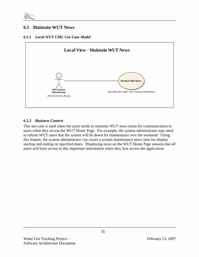
Water Use Tracking Project – February 13, 2007 Software Architecture Document
35
6.5 Maintain WUT News
6.5.1 Local WUT UML Use Case Model
Local View - Maintain WUT News
(from Maintain Water Use Tracking Information)
Maintain WUT News
WUT System Administrator
(from Technical Actors)
6.5.2 Business Context This use case is used when the actor needs to maintain WUT news items for communication to users when they access the WUT Home Page. For example, the system administrator may need to inform WUT users that the system will be down for maintenance over the weekend. Using this feature, the system administrator can create a system maintenance news item for display starting and ending on specified dates. Displaying news on the WUT Home Page ensures that all users will have access to this important information when they first access the application.

Water Use Tracking Project – February 13, 2007 Software Architecture Document
36
6.6 View Map
6.6.1 Local WUT UML Use Case Model
Local View - View Map
(from View Water Use Permit Information)
View Map
General WUT User
(from Actors)
6.6.2 Business Context This use case will be used when an actor needs to view water use permit (WUP) information spatially using a map created with the functionality provided by a Geographic Information Systems (GIS). Viewing WUP information in a pre-defined report format can be very effective from the point of view of efficiency, organization, and the presentation of large amounts of data. Even so, a report is simply a one-dimensional presentation of information when that information has at its basis a spatial context. When viewing WUP information in a report, the subtlety and complexity of the spatial relationships cannot be presented at all or is, at best, difficult to comprehend. The viewing of information within its spatial context is exactly where GIS excels and is the primary reason for this View Map Use Case. When additional GIS layers are added to a map, the multi-dimensional presentation of information provides for a richness of analysis simply not possible using a report format. Although not intended exclusively for this actor, one of the primary actors who will use this use case is the WUP Evaluators. They are responsible for the analysis of all new, modified, and renewed WUPs. During the analysis process, the evaluator will frequently require access to a map to view WUP data within its spatial context. Doing so will enable the evaluator to view other important data within the area of interest resulting in a far richer analytical effort. By having the ability to add different GIS layers to the map, the evaluator will have more information at their disposal to assist in their analytical effort. Add to this the capability to pan, zoom, and print at any time, the evaluator will have all the information and functionality required to make better, more informed decisions.

Water Use Tracking Project – February 13, 2007 Software Architecture Document
37
6.7 View Report
6.7.1 Local WUT UML Use Case Model
(from View Water Use Permit Information)
View Report
Local View - View Report
General WUT User
(from Actors)
6.7.2 Business Context This use case will be used when an actor needs to produce a report from within the WUT Report Library. It is anticipated that the WUT System will have a large number of reports available in its report library. Every report use case within the WUT Report Library will extend this use case as appropriate for the specific report. A report in this library provides information in a pre-defined format. While the information content of the report is pre-defined, the system enhances the flexibility of the report by providing the actor with the capability to optionally limit the information in any given report to the actor’s specific area of interest (e.g., a specific county). This is accomplished through report specifications. While a given report may be run frequently, the information content will often vary from report to report based upon the run-time report specifications given by the actor. This use case provides support for the numerous reports within the WUT Report Library. Once the actor specifies the report of interest and optionally supplies any run-time report criteria, the system will retrieve the information for the actor and present it in the pre-defined format. The actor can then choose to simply view the report online or download the report for analysis, printing, or saving as an electronic file in a variety of supported formats.

Water Use Tracking Project – February 13, 2007 Software Architecture Document
38
6.8 View Water Use Permit
6.8.1 Local WUT UML Use Case Model
Local View - View Water Use Permit
(from View Water Use Permit Information)
View Water Use Permit
General WUT User
(from Actors)
6.8.2 Business Context This use case will be used when an actor needs to view information about a specific water use permit. This water use permit information is collected at the time the permit is submitted and approved by the District. A water use permit is required from the District when: • Total capacity of the permit is greater than or equal to 1 million gallons per day • Total annual average quantities for the permit is greater than or equal to 100,000 gallons per
day • Well diameter is greater than or equal to 6 inches • Surface water withdrawal pipe diameters are greater than or equal to 4 inches • Cumulative well diameters greater than or equal to 6 inches, if in MIA and constructed after
April 11, 1994, and is not a replacement well of same or smaller diameter of one being plugged
• If withdrawal is likely to cause significant adverse impacts to existing water or land uses, or the surrounding water resources
The actual area of the permit is digitized as a polygon into a GIS layer based on color infrared (CIR) digital orthophoto quarter quadrangles (DOQQs). The general data that is collected with the permit includes the permittee information, acreage amounts, permitted quantities, water use information, expiration date, and aquifer information. This information will be displayed to the actor, with the option to "drill-down" to get more detailed information, such as well information or actual pumpage quantities.

Water Use Tracking Project – February 13, 2007 Software Architecture Document
39
6.9 View Water Use Permit Search
6.9.1 Local WUT UML Use Case Model
General WUT User
(from Actors)
Local View - View Water Use Permit Search
(from View Water Use Permit Information)
View Water Use Permit Search
6.9.2 Business Context This use case will be used when an actor needs to search for and identify a water use permit for analysis. This use case, as well as the View Map Use Case, is considered among the class of Find use cases. A Find use case provides the capability to identify, locate, and access information within the WUT System, as it pertains to a water use permit. The View Water Use Permit Search use case enables the actor to efficiently and effectively search for and identify permits that meet a given search criteria. The system returns basic information about the permit with the ability to get more detailed information regarding the permit (i.e., wells, Net Benefits, compliance data). This use case is used in support of the View Water Use Permit Use Case.

Water Use Tracking Project – February 13, 2007 Software Architecture Document
40
7 WUT Logical View
7.1 Introduction As mentioned early in Section 2, WUT Architectural Representation, the WUT software architecture will be represented in this document as both the set of architecturally significant decisions that have been made by the WUT Project Development Team and as a series of architectural views. The first of these architectural views, WUT Use Case View, was presented in Section 6. This section continues this representation with the WUT Logical View. The WUT Logical View addresses the business and functional requirements of the system and is based upon the WUT Design Model, which was created through the use case realization process. Because not all of design is architecturally significant, only those architecturally significant components of the WUT Design Model will be presented in this section. These components are those UML model elements within the design model that reflect or incorporate the architecturally significant decisions presented in Section 5, WUT Architecturally Significant Decisions. As an example, consider the decision by the WUT Project Development Team to design the WUT System using an Object-Oriented (OO) Development Methodology. Within the WUT Logical View, UML model elements from the design model would be presented that illustrate how an OO development methodology has influenced or is reflected in this model. This approach will be followed for the following architecturally significant decisions: • Object-Oriented Software Development Methodology • Layering • Boundary, Control, and Entity Design Pattern • Security Architecture • Object-Relational Broker Design Pattern • Trusted User Design Pattern Note that the balance of the architecturally significant decisions will be reflected in the WUT Deployment View. This includes the following decisions: • Relational Database Management System • Distributed 3-Tier Client/Server Architecture • Thin Web Client Architecture • WUT Technical Architecture

Water Use Tracking Project – February 13, 2007 Software Architecture Document
41
7.2 Object-Oriented Software Development Methodology
7.2.1 Overview As discussed in Section 5.3, the WUT System is being developed using an object-oriented development methodology; a methodology that is based on the concepts of classes, objects, data abstraction, encapsulation, messages, and inheritance. The decision to develop the WUT System using an object-oriented development methodology is one of the primary architectural decisions that have been made by the WUT Project Development Team. This methodology informs the project development team’s approach to analysis and design, which, in turn, is reflected in the numerous interaction and class diagrams that comprise the WUT Design Model. Later during construction, the WUT Design Model will be physically implemented using object-oriented programming languages and techniques.

Water Use Tracking Project – February 13, 2007 Software Architecture Document
42
7.2.2 UML Model Elements from the WUT Design Model In the class diagram in Figure 6, the architecturally significant model elements within this diagram illustrate the OO development methodology being utilized by the WUT Project Development Team to create the WUT Design Model. These model elements are considered architecturally significant because of the central importance these classes have to the whole of the WUT application.
Architecturally Significant Model Elements
Water Use Permit
Withdrawals
Well Construction
Permittee
Owner
Contractor
County
Basin
Watersheds
0..1
+Is In
Water Use Permit to Watersheds
0..*
+Contains
0..1
+Is In
Water use Permit to Basin 0..*
+Contains
1..
+Is in
Water Use Permit to County
0..*
+Contains
1
+Completes
Contractor to Well Construction
0..*
+Is Completed By
1
+Owns
Owner to Water Use Permit 0..*
+Is Owned By
1
+Has
Permittee to Water Use Permit
0..*+Is Permitted To
1
+Submits
Contractor to Water Use Permit
+Is Submitted By
1+Has
0..1+Is On
1+Has
Water Use Permit to Withdrawals
0..*+Is On
Figure 6 – Architecturally Significant Model Elements

Water Use Tracking Project – February 13, 2007 Software Architecture Document
43
7.3 Layering
7.3.1 Overview As discussed in Section 5.4, a layer represents a slice through the software architecture, with each layer representing a grouping of related functionality. Layering provides a way to decompose the system into more manageable software components and restrict inter-system dependencies with the goal being to design a system that is more loosely coupled and thus easier to maintain. An important characteristic of the layers design pattern is the directional dependencies that exist between the various layers. That is, a software component within a given layer should ideally access only components within its own layer or components in the layers beneath it. This directional dependency rule is one of the mechanisms by which the goal of the layers design pattern is realized.
7.3.2 UML Model Elements from the WUT Design Model
<<layer>>Presentation
<<layer>>Business Logic
<<layer>>Data Access
WUT Problem Domain Layers
Figure 7 – WUT Problem Domain Layers

Water Use Tracking Project – February 13, 2007 Software Architecture Document
44
Presentation Layer The WUT Presentation Layer provides support for the interactions between the actors, or the users of the system, and the software system itself through the presentation of user interfaces. Business Logic Layer The WUT Business Logic Layer provides support for application specific business processes, as well as, the application and enforcement of business and data integrity rules. Data Access Layer The WUT Data Access Layer provides support for data access and persistence in conjunction with the WUT relational database supported by Oracle RDBMS. Each of these layers is comprised of numerous classes. To illustrate this approach, stereotyped control classes from the WUT Business Logic Layer are provided in the class diagram in Figure 8.
Process WUT System Startup Controller
(from Process WUT System Startup)
View WUP Search Controller
(from View WUP Search)
View WUP Controller
(from View WUP)
Stereotyped Control Classes within the WUT System Business Logic Layer
View WUT Report Controller
View Withdrawal Controller View Well Construction Controller
View Map Controller
Figure 8 – Stereotyped Control Classes

Water Use Tracking Project – February 13, 2007 Software Architecture Document
45
7.4 Boundary, Control, and Entity Design Pattern
7.4.1 Overview As discussed in Section 5.5, the goal of the Boundary, Control, and Entity design pattern is to decompose an application into three distinct types of objects: • Boundary Objects • Control Objects • Entity Objects Boundary objects are responsible for supporting communications between the system’s external environment (e.g., its users, other systems, or hardware devices) and its internal workings (i.e., control and entity objects). Boundary classes will also be used to support communications with legacy systems or hardware devices external to the system. Control objects are responsible for application specific business logic. In addition, these object types also function as an intermediary between the system’s various boundary and entity objects. Entity objects are the data aware objects within the system. These objects are responsible for providing support for the entities that constitute the problem domain (e.g., water use permits, withdrawal wells, etc.). Collaborating together, the various boundary, control, and entity objects within the BCE design pattern realize the behavior documented in the system’s Use Case Model, as shown in Figure 9.
Figure 9 – The Packaging of the WUT Boundary, Control, and Entity Objects

Water Use Tracking Project – February 13, 2007 Software Architecture Document
46
There is a natural association between the WUT layers, described in Section 7.3, Layering, and boundary, control, and entity objects. That is, boundary objects are associated with the Presentation Layer, control objects are associated with the Business Object Layer, and entity objects are associated with the Data Access Layer. Within the WUT Design Model, this association is reflected in the WUT interaction and class diagrams as well as the Business Logic, Data Access, and Presentation packages.
7.4.2 UML Model Elements from the WUT Design Model In the sections that follow, the stereotyped View of Participating Classes (VOPC) class diagram from each of use case realization in WUT Design Model will be provided. These VOPC class diagrams will illustrate the application of the Boundary, Control, and Entity design pattern in the use case realization process that was followed to create the design model.
7.4.2.1 Process Database Replication Use Case – Stereotyped VOPC
ProcessDatabaseController
DataBaseEntities
Process Database Replication - VOPC
The controller wil l be a PL/SQL stored procedure triggered from an insert, update, or delete.

Water Use Tracking Project – February 13, 2007 Software Architecture Document
47
7.4.2.2 Process WUT System Startup Use Case – Stereotyped VOPC
Default LogonController
News Controller
(from Maintain WUT News)
QuickLink Controller
QuickLinks
WUTPrinciple
Process WUT System Startup - VOPC
ControlBase
NewsItems
(from Maintain WUT News)

Water Use Tracking Project – February 13, 2007 Software Architecture Document
48
7.4.2.3 Maintain WUT News Use Case – Stereotyped VOPC
newsDefault AddNewsItem EditNewsItem InactiveNews
NewsItems
NewsControl
Maintain WUT News - VOPC

Water Use Tracking Project – February 13, 2007 Software Architecture Document
49
7.4.2.4 View Map Use Case – Stereotyped VOPC
View Map - VOPC
ViewMapDefault
MapDotNetServ ice(from Non-Human Actors)
ViewMapController

Water Use Tracking Project – February 13, 2007 Software Architecture Document
50
7.4.2.5 View Report Use Case – Stereotyped VOPC
Report
ReportController
Reports
View Report - VOPC
Report specific controllers wil l be created based on the selected report.
ReportxxxController
ReportControlBase
ReportxxxCriteria.aspx
ReportPageBase
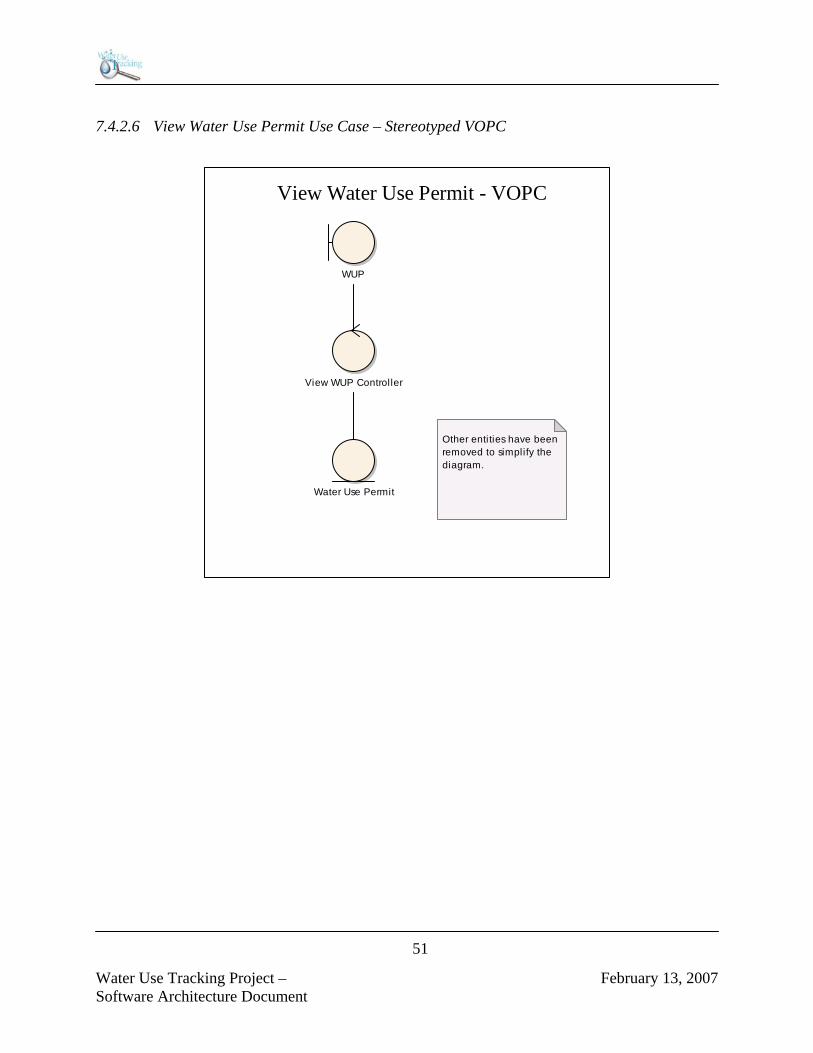
Water Use Tracking Project – February 13, 2007 Software Architecture Document
51
7.4.2.6 View Water Use Permit Use Case – Stereotyped VOPC
WUP
View WUP Controller
Water Use Permit
View Water Use Permit - VOPC
Other entities have been removed to simplify the diagram.

Water Use Tracking Project – February 13, 2007 Software Architecture Document
52
7.4.2.7 View Water Use Permit Search Use Case – Stereotyped VOPC
WupOpen
View WUP Search Controller
Water Use Permit
Permittee
Owner
Contractor
County
Watersheds
Basin
Withdrawals
Well Construction
Other entites have been removed to simplify the diagram.
View Water Use Permit Search - VOPC

Water Use Tracking Project – February 13, 2007 Software Architecture Document
53
7.5 Security Architecture
7.5.1 Overview As discussed in Section 5.8, the WUT security architecture is organized along two dimensions: • Application Level Security • System Level Security System level security is concerned with controlling access to the system in the first place. In contrast, application level security is concerned with proactively controlling access to WUT features, functions, and data after a user has gained access to the system. Rather than allowing the user to request access when they do not have the proper security to make the request and then negatively responding to this request, the WUT application security will proactively deny the user access by disabling the feature or function in the GUI. In this way, the user cannot request access to a feature or function unless they are authorized to do so. The WUT application level security will utilize a role-based security architecture. The WUT Roles, and the capabilities associated with each role, will be formally documented in the WUT Access Criteria, an Elaboration/Construction Phase deliverable. When a user accesses the WUT application from SWFWMD’s Intranet, the control objects related to each boundary object within the WUT Design Model will be responsible for identifying each user and will use the .Net Framework to accomplish this identification task. Specifically, the IsInRole function will be used to establish the user’s group membership and their group membership will be the basis for determining the user’s access privileges consistent with the WUT Access Criteria. If a given user has not been specifically assigned to a WUT Group, the user’s role will default to the WUT General User Role. Doing so will ensure that all SWFWMD users have at least limited access to the WUT system without having to incur the overhead and maintenance associated with having to assign each and every SWFWMD staff to a WUT Group. To illustrate the WUT security architecture, the WUT Process System Startup Use Case Realization’s View of Participating Classes class diagram is provided. This use case implements the IPrincipal interface to provide facilities for integrated .NET security checks at a use case level. This IPrincipal implementation provides an additional method, HasAccess, which can be used in lieu of the WUTPrincipal.IsInRole method. The HasAccess method provides more granular access control for the WUT application, while the WUTPrincipal.IsInRole method is overridden to support the same level of control, but through a custom string format for the 'role' parameter. The class also manages the loading and saving of the WUTPrincipal object from the user's Session object with a value name provided by the caller. For debug purposes, you can define the NO_SECURITY conditional compilation variable in Configuration Properties/Build/Code Generation/Conditional Compilation Constants of the project properties dialog. This object cannot be instantiated directly, but must be "Installed" using one of the public static methods (see InstallOnAppDomain and InstallOnAspNetThread).

Water Use Tracking Project – February 13, 2007 Software Architecture Document
54
7.5.2 UML Model Elements from the WUT Design Model
SWFWMD.WUT.UI.Web::_Default
# PageHeaderMain: SWFWMD.WUT.UI.WebControl.PageHeader# RepeaterQuickLink: System.Web.UI.WebControls.Repeater# CodeDropDownListPurpose: SWFWMD.WUT.UI.WebControl.CodeDropDownList# DropDownList1: System.Web.UI.WebControls.DropDownList# RepeaterNews: System.Web.UI.WebControls.Repeater
- Page_Load(object, System.EventArgs) : void# «property» QuickLinkData() : DataTable# «property» NewsData() : DataTable~ OnInit(EventArgs) : void- Initial izeComponent() : void
PageSWFWMD.WUT.UI.Web::PageBase
- pageUseCaseType: UseCaseType- businessRuleControl: BusinessRuleControl = null- logonControl: LogonControl = null- newsControl: NewsControl = null- notesControl: NotesControl = null- reportControl: ReportControl = null- WupSearchControl: WupSearchControl = null- wupControl: WupControl = null
+ PageBase()# «property» BusinessController() : BusinessRuleControl# «property» LogonController() : LogonControl# «property» NewsController() : NewsControl# «property» NotesControl ler() : NotesControl# «property» ReportController() : ReportControl# «property» WupSearchControl ler() : WupSearchControl# «property» WupControl ler() : WupControl~ OnInit(EventArgs) : void+ HasAccess(AccessLevel) : bool+ HasAccess(UseCaseType, AccessLevel) : bool+ HasAccess(UseCaseType, AccessLevel, bool) : bool+ HasAccess(AccessLevel, bool) : bool# «property» PageUseCaseType() : UseCaseType~ OnLoad(EventArgs) : void# GetDisplayableTypedRowValue(object, string) : string- DisplayServerVariables() : void- CleanUpSessionState() : void# GetValueFromUrlOrSessionState(string, string, object) : object# GetValueFromUrlOrSessionState(string, string, System.Type, string) : object# GetValueFromUrlOrViewState(string, string, object) : object# GetValueFromUrlOrViewState(string, string, System.Type, string) : object# GetValueFromQueryString(string, object) : object# GetValueFromQueryString(string, System.Type, string) : object# CorrectRouteFormat(string) : string# Escape(string) : string# DivideBy1000(long) : string# DivideBy1000(object) : string# DivideBy1000(string) : string# GetNoteImage(long) : string# GetNotesLink(UseCaseType, string, string) : string# GetIDFromLabel(System.Web.UI.WebControls.WebControl, string) : long# GetValueFromControl(System.Web.UI.WebControls.WebControl, string, System.Type) : object+ EncryptStringForUrl(string) : string+ DecryptEncodedString(string) : string+ EncryptString(string) : string+ DecryptString(string) : string- InitializeEncryptionProvider(TripleDESCryptoServiceProvider) : void- ByteArrayToString(byte[]) : string- StringToByteArray(string) : byte[]- MemoryStreamToString(MemoryStream) : string- InitializeComponent() : void+ SecureDataGrid(DataGrid, Control, System.Type) : void
SWFWMD.WUT.Business::LogonControl
+ QuickLinkLoadAll() : DataTable+ NewsItemLoadCurrent() : DataTable
SWFWMD.WUT.Business::ControlBase
- bsrlDataAccess: BSRLDataAccess = null- bsrlprmDataAccess: BSRLPRMDataAccess = null- bsrlprmvlDataAccess: BSRLPRMVLDataAccess = null- bsrlrngDataAccess: BSRLRNGDataAccess = null- ntatchDataAccess: NTATCHDataAccess = null- ntDataAccess: NTDataAccess = null- nwsitmDataAccess: NWSITMDataAccess = null- qcklnkDataAccess: QCKLNKDataAccess = null- rdt004DataAccess: RDT004DataAccess = null- rdt006DataAccess: RDT006DataAccess = null- rptDataAccess: RPTDataAccess = null- statlgDataAccess: STATLGDataAccess = null- wup_countyDataAccess: WUP_COUNTYDataAccess = null- wup_predominant_useDataAccess: WUP_PREDOMINANT_USEDataAccess = null- wut001DataAccess: WUT001DataAccess = null- wut094DataAccess: WUT094DataAccess = null
# «property» BSRLDataAccessor() : BSRLDataAccess# «property» BSRLPRMDataAccessor() : BSRLPRMDataAccess# «property» BSRLPRMVLDataAccessor() : BSRLPRMVLDataAccess# «property» BSRLRNGDataAccessor() : BSRLRNGDataAccess# «property» NTATCHDataAccessor() : NTATCHDataAccess# «property» NTDataAccessor() : NTDataAccess# «property» NWSITMDataAccessor() : NWSITMDataAccess# «property» QCKLNKDataAccessor() : QCKLNKDataAccess# «property» RDT004DataAccessor() : RDT004DataAccess# «property» RDT006DataAccessor() : RDT006DataAccess# «property» RPTDataAccessor() : RPTDataAccess# «property» STATLGDataAccessor() : STATLGDataAccess# «property» WUP_COUNTYDataAccessor() : WUP_COUNTYDataAccess# «property» WUP_PREDOMINANT_USEDataAccessor() : WUP_PREDOMINANT_USEDataAccess# «property» WUT001DataAccessor() : WUT001DataAccess# «property» WUT094DataAccessor() : WUT094DataAccess# Escape(string) : string
DataAccessBaseSWFWMD.WUT.DataAccess::QCKLNKDataAccess
+ LoadAll() : DataTable- GetLoadAllCommand(OracleConnection) : OracleCommand+ LoadById(long) : DataTable- GetLoadByIdCommand(OracleConnection, long) : OracleCommand+ Add(long*, string, string, string) : void- GetAddCommand(OracleConnection) : OracleCommand- GetAddCommand(OracleConnection, string, string, string) : OracleCommand+ Modify(long, string, string, string) : void- GetModifyCommand(OracleConnection) : OracleCommand- GetModifyCommand(OracleConnection, long, string, string, string) : OracleCommand+ Remove(long, string) : void- GetRemoveCommand(OracleConnection) : OracleCommand- GetRemoveCommand(OracleConnection, long, string) : OracleCommand+ Save(DataTable) : void
DataAccessBaseSWFWMD.WUT.DataAccess::NWSITMDataAccess
+ LoadAll() : DataTable- GetLoadAllCommand(OracleConnection) : OracleCommand+ LoadById(long) : DataTable- GetLoadByIdCommand(OracleConnection, long) : OracleCommand+ LoadCurrent() : DataTable- GetLoadCurrentCommand(OracleConnection) : OracleCommand+ LoadActive() : DataTable- GetLoadActiveCommand(OracleConnection) : OracleCommand+ LoadInactive() : DataTable- GetLoadInactiveCommand(OracleConnection) : OracleCommand+ Add(long*, string, DateTime, DateTime, string, string) : void- GetAddCommand(OracleConnection) : OracleCommand- GetAddCommand(OracleConnection, string, DateTime, DateTime, string, string) : OracleCommand+ Modify(long, string, DateTime, DateTime, string, string) : void- GetModifyCommand(OracleConnection) : OracleCommand- GetModifyCommand(OracleConnection, long, string, DateTime, DateTime, string, string) : OracleCommand+ Remove(long, string) : void- GetRemoveCommand(OracleConnection) : OracleCommand- GetRemoveCommand(OracleConnection, long, string) : OracleCommand+ Save(DataTable) : void
«enumeration»SWFWMD.WUT::
AccessLev el
+ None: int+ Read: int+ Full: int
«enumeration»SWFWMD.WUT::UseCaseType
+ GenerateWellPackage: int+ ProcessDatabaseReplication: int+ ProcessWutSystemStartup: int+ MaintainBusinessRuleParameters: int+ MaintainQuickLinks: int+ MaintainWaterUseEstimates: int+ MaintainWutNews: int+ ViewChangeInUseTypeOrOwner: int+ ViewComplianceInformation: int+ ViewCropReportInformation: int+ ViewLandUseInformation: int+ ViewMitigationOfMflImpacts: int+ ViewNetBenefitSummary: int+ ViewResourceInformation: int+ ViewUseOfLapsedQuantities: int+ ViewUseOfQuantitiesAssociatedWithDistrictProjects: int+ ViewWaterUsePermit: int+ ViewWaterUsePermitSearch: int+ ViewWaterWithdrawalCredit: int+ ViewWellConstructionInformation: int+ ViewWithdrawalPumpageInformation: int+ ViewMap: int+ ViewLapsedOrProjectQuantitiesSummary: int+ ViewReport: int+ Report: int+ ReportXXX: int
IPrincipalSWFWMD.WUT::WUTPrincipal
- originalPrincipal: IPrincipal- accessLevelsHT: Hashtable = new Hashtable()
# WUTPrincipal(IPrincipal)+ Instal lOnAspNetThread(HttpSessionState, string) : WUTPrincipal+ Instal lOnAppDomain() : WUTPrincipal+ IsInRole(string) : bool+ «property» Identity() : IIdentity+ «property» OriginalPrincipal() : IPrincipal+ HasAccess(UseCaseType, AccessLevel) : bool- getUseCaseAndPermissionFromRoleString(String, UseCaseType*, AccessLevel*) : void- initial izeAccessLevels() : void
Process WUT System Startup
+pageUseCaseType
+qcklnkDataAccess
+nwsitmDataAccess
+logonControl

Water Use Tracking Project – February 13, 2007 Software Architecture Document
55
7.6 Object-Relational Broker Design Pattern
7.6.1 Overview As discussed in Section 5.10, the persistent data structure cannot be mechanically derived from the structure of entity classes in the design model when using an object-oriented development methodology in combination with relational technology. The primary reason for not being able to derive this structure from the design model is the constraints imposed on the design of the relational data model by the rules of normalization, or the set of techniques for organizing data into tables within a relational database. As a result, and to reconcile the differences between the unique demands of an object-oriented development methodology and the relational structures within a RDBMS, the WUT software architecture will require a specialized control object called an object-relational broker. This object type is based upon a design pattern with the same name, the Object-Relational Broker design pattern. This design pattern is concerned with the implementation of the functionality required to: • Store the data encapsulated within an entity object in the appropriate tables within the a
relational database • Validate the data encapsulated within an entity object based upon data integrity rules defined
within the data dictionary • Retrieve and instantiate an entity object whose data has been previously been stored in a set
of normalized, relational tables Within the WUT Design Model, each control object paired with an entity object is an object-relational broker. In the following class diagram, based upon the Maintain WUT News Use Case Realization’s VOPC, the following classes are provided to illustrate this design pattern: • Default – The Maintain WUT News web form • NewsController – The control object related to the Maintain News’ default web form • NWSITMDataAccess – The WUT News’ object-relational broker • NWSITMDataTable – The WUT News’ entity object in the form of an ADO collection

Water Use Tracking Project – February 13, 2007 Software Architecture Document
56
7.6.2 UML Model Elements from the WUT Design Model
PageBaseMaintain WUT News::_Default
# PageHeaderMain: SWFWMD.WUT.UI.WebControl.PageHeader# HyperLinkAddNew: System.Web.UI.WebControls.HyperLink# DataGridNews: SWFWMD.WUT.UI.WebControl.EditDataGrid# LabelMessage: System.Web.UI.WebControls.Label- DefaultSortExpression: string = "NWSITM_START_DT_TM"- DefaultSortDirection: string = "DESC"- MaintainItemText: string = "News Item"- maxVal: int = 1000000
- Page_Load(object, System.EventArgs) : void- BindData(int, NewsDataSet) : void- DataGridNews_ItemDataBound(object, System.Web.UI.WebControls.DataGridItemEventArgs) : void- RenderHeader(object, System.Web.UI.WebControls.DataGridItemEventArgs) : void- RenderPager(object, System.Web.UI.WebControls.DataGridItemEventArgs) : void- ResetCounts(NewsDataSet) : void- CheckPageIndex(int, int) : int- DataGridNews_DeleteCommand(object, System.Web.UI.WebControls.DataGridCommandEventArgs) : void- DataGridNews_EditCommand(object, System.Web.UI.WebControls.DataGridCommandEventArgs) : void- DataGridNews_ItemCreated(object, System.Web.UI.WebControls.DataGridItemEventArgs) : void- DataGridNews_PageIndexChanged(object, System.Web.UI.WebControls.DataGridPageChangedEventArgs) : void- DataGridNews_SortCommand(object, System.Web.UI.WebControls.DataGridSortCommandEventArgs) : void- LinkButtonViewAll_Click(object, System.EventArgs) : void- LinkButtonViewByPage_Click(object, System.EventArgs) : void~ OnInit(EventArgs) : void- Initial izeComponent() : void
ControlBaseNewsControl
+ LoadActiveNews() : NewsDataSet+ LoadInactiveNews() : NewsDataSet+ LoadById(long) : NewsDataSet+ Insert(string, DateTime, DateTime, string, string) : long+ Update(long, string, DateTime, DateTime, string, string) : void+ Delete(long, string) : void
DataAccessBaseNWSITMDataAccess
+ LoadAll() : DataTable- GetLoadAllCommand(OracleConnection) : OracleCommand+ LoadById(long) : DataTable- GetLoadByIdCommand(OracleConnection, long) : OracleCommand+ LoadCurrent() : DataTable- GetLoadCurrentCommand(OracleConnection) : OracleCommand+ LoadActive() : DataTable- GetLoadActiveCommand(OracleConnection) : OracleCommand+ LoadInactive() : DataTable- GetLoadInactiveCommand(OracleConnection) : OracleCommand+ Add(long*, string, DateTime, DateTime, string, string) : void- GetAddCommand(OracleConnection) : OracleCommand- GetAddCommand(OracleConnection, string, DateTime, DateTime, string, string) : OracleCommand+ Modify(long, string, DateTime, DateTime, string, string) : void- GetModifyCommand(OracleConnection) : OracleCommand- GetModifyCommand(OracleConnection, long, string, DateTime, DateTime, string, string) : OracleCommand+ Remove(long, string) : void- GetRemoveCommand(OracleConnection) : OracleCommand- GetRemoveCommand(OracleConnection, long, string) : OracleCommand+ Save(DataTable) : void
DataTableSystem.Collections.IEnumerable
«inner class»NWSITMDataTable
- columnNWSITM_ID: DataColumn- columnNWSITM_TTL_NM: DataColumn- columnNWSITM_START_DT_TM: DataColumn- columnNWSITM_END_DT_TM: DataColumn- columnNWSITM_DSCR: DataColumn- columnACTN_USER_NM: DataColumn- columnACTN_DT_TM: DataColumn- columnNT_CNT_NBR: DataColumn+ «event» NWSITMRowChanged: NWSITMRowChangeEventHandler+ «event» NWSITMRowChanging: NWSITMRowChangeEventHandler+ «event» NWSITMRowDeleted: NWSITMRowChangeEventHandler+ «event» NWSITMRowDeleting: NWSITMRowChangeEventHandler
~ NWSITMDataTable()~ NWSITMDataTable(DataTable)+ «property» Count() : int~ «property» NWSITM_IDColumn() : DataColumn~ «property» NWSITM_TTL_NMColumn() : DataColumn~ «property» NWSITM_START_DT_TMColumn() : DataColumn~ «property» NWSITM_END_DT_TMColumn() : DataColumn~ «property» NWSITM_DSCRColumn() : DataColumn~ «property» ACTN_USER_NMColumn() : DataColumn~ «property» ACTN_DT_TMColumn() : DataColumn~ «property» NT_CNT_NBRColumn() : DataColumn+ «indexer» this(int) : NWSITMRow+ AddNWSITMRow(NWSITMRow) : void+ AddNWSITMRow(long, string, System.DateTime, System.DateTime, string, string, System.DateTime, System.Decimal) : NWSITMRow+ FindByNWSITM_ID(long) : NWSITMRow+ GetEnumerator() : System.Collections.IEnumerator+ Clone() : DataTable# CreateInstance() : DataTable~ InitVars() : void- InitClass() : void+ NewNWSITMRow() : NWSITMRow# NewRowFromBuilder(DataRowBuilder) : DataRow# GetRowType() : System.Type# OnRowChanged(DataRowChangeEventArgs) : void# OnRowChanging(DataRowChangeEventArgs) : void# OnRowDeleted(DataRowChangeEventArgs) : void# OnRowDeleting(DataRowChangeEventArgs) : void+ RemoveNWSITMRow(NWSITMRow) : void
Maintain WUT News - Object-Relational Broker Design Pattern

Water Use Tracking Project – February 13, 2007 Software Architecture Document
57
7.7 Trusted User Design Pattern As discussed in Section 5.11 and to enable the WUT object-relational brokers to access the data store in the relational database on behalf of a user, the WUT System will connect to the Oracle RDBMS through its middle tier utilizing a trusted user architecture. The major advantage of this access architecture is connection pooling, which enables an application to use a connection from a pool of connections instead of establishing a new connection for each use. To establish a connection to the Oracle RDBMS, the WUT middle tier will provide a secured username and password, which will be authenticated by the Oracle RDBMS. Having established an Oracle connection, the trusted user will submit requests to the WUT relational database on behalf of the users. The WUT application level security will proactively determine whether or not a given user has the permission to submit a given request. If a user does not have permission, the user will not be allowed access. Thus, the WUT application level security ensures that the WUT middle tier will only receive and process valid requests for WUT data. The username and password for the trusted user will be stored in the application’s Web.Config file as part of the database connection string. The Web.Config file can be edited in a text editor at any time if the username and/or password change.

Water Use Tracking Project – February 13, 2007 Software Architecture Document
58
8 WUT Deployment View
8.1 Introduction In Section 7, the WUT Logical View, the WUT software architecture was represented by the architecturally significant UML model elements from the WUT Design Model that reflected the following architecturally significant decisions: • Object-Oriented Software Development Methodology • Layering • Boundary, Control, and Entity Design Pattern • Security Architecture • Object-Relational Broker Design Pattern • Trusted User Design Pattern In this final architectural view, the likely physical network and hardware configurations on which the WUT System will be deployed will be presented. This view is based upon the WUT Deployment Model, which has been created in Enterprise Architect. Similar to the WUT Logical View, the WUT Deployment View has been informed by a number of the architecturally significant decisions presented in Section 2.2 including: • Relational Database Management System • Distributed 3-Tier Client/Server Architecture • Thin Web Client Architecture • WUT Technical Architecture Following an overview of these decisions, the WUT UML Deployment Model will be presented.
8.1.1 Relational Database Management System As described in Section 5.9, the WUT System will utilize an Oracle RDBMS and relational databases created within this environment to store the project’s persistent information including: • Regulatory Database (RDB) including Water Use Permit information • Water Management Database (WMDB) including data on ground and surface water levels,
water quality, stream flows, and climatological trends • Well Construction Database (WCT) including well construction details (i.e., well depth,
casing size, casing type, etc.) • Geographic data which will be stored using ESRI’s Spatial Database Engine In addition to this persistent information, some application business logic will be implemented as Oracle RDBMS stored procedures for performance reasons.
8.1.2 Distributed 3-Tier Client/Server Architecture As described in Section 5.6, each conceptual component of a distributed 3-tier client/server architecture must be individually discussed in order to ensure that a clear understanding of this architecture has been conveyed.

Water Use Tracking Project – February 13, 2007 Software Architecture Document
59
Client/Server Within the context of a distributed 3-tier client/server architecture, the phrase ‘client/server’ indicates that multiple client and server processor nodes will be used to execute the software written to support the project’s business and functional requirements. In addition, and at any given point in time, each individual client processor node will only provide support for a single client. In contrast, each server processor node will provide support for multiple clients. Server processor nodes could include, but are not limited to, one or more application web and RDBMS servers. 3-Tier The use of the phrase ‘3-tier’ within the context of this distribution pattern indicates that the software written to support the project’s business and functional requirements will be divided into 3 logical partitions where each partition provides a distinct service. The three logical partitions are: • Presentation Services • Business Services • Data Services Distributed The use of the term ‘distributed’ within the context of this pattern indicates that the three logical partitions will be spread among the various client and server processor nodes discussed above. Further, this distribution of functionality will be specialized in terms of the software executed on each of the processor nodes. That is, client processor nodes will specialize in providing support for the presentation services. In contrast, server processor nodes will specialize in providing support for business and data services. In some cases, the specialization at the server processor node level can include the separation of support for the business and data services across distinct server nodes, which enables the implementation of extremely high-performance server nodes (e.g., AIX servers) in support of the RDBMS.
8.1.3 Thin Web Client Architecture As discussed in Section 5.7, the Thin Web Client architecture pattern builds upon both the layering and distribution patterns discussed previously in that this architecture pattern provides support for the WUT Presentation Layer utilizing a standard web browser on the client processor node. Within the context of this architecture, the browser functions as a generalized user interface device and most user interactions with the system will be conducted through the browser. Beginning with the WUT startup page, each interaction with the system returns an HTML page. This page serves as the browser’s instructions on how to render the text and graphics displayed to the user. This architecture requires minimal client processor node computing power and has few client configuration dependencies. As a result, the scope of supported client processor nodes is maximized and users could conceivably access the WUT System by means of a hardware device as powerful as a desktop computer or as minimal as a Pocket PC or a web-enabled cell phone.

Water Use Tracking Project – February 13, 2007 Software Architecture Document
60
8.1.4 WUT Technical Architecture As discussed in Section 5.12, the technical architecture decisions that have been made by the WUT Project Development Team include the following technologies: • Windows 2000 Server • Oracle RDBMS • GIS Technologies
ArcSDE ArcIMS MapDotNet
• Microsoft .NET Development Technologies Visual Studio .NET ADO.NET ASP.NET Oracle Data Provider for .NET (ODP.NET)
• Crystal Reports for Visual Studio .NET These technologies primarily impact the WUT Middleware and System Software Layers. Recall from the discussion presented in Section 5.4.2, Solution Space Layers, that the Middleware and System Software Layers are solution space layers that provide the services specific to the technical architecture of the deployment environment. These service-based layers provide the functionality required by the problem domain layers in order to fulfill their responsibilities. Thus, these layers are essential to successfully deploy the software system.
8.2 WUT UML Deployment Model The WUT UML Deployment Model is presented in Figure 10 on the following page. In addition to being informed by the architecturally significant decisions discussed above, this model is consistent with, and supports the layers design pattern discussed in Section 5.4, as well as the BCE design pattern discussed in Section 5.5.

Water Use Tracking Project – February 13, 2007 Software Architecture Document
61
Client Workstation
Application Serv er
Database Serv er
Internet Explorer
Oracle RDBMSArcSDEWUT Relation Database
Web ServerBusiness Application Server
Web Server· Internet Information Server· .NET Framework· ASP.NET
Business Application Server· Internet Information Server· .NET Framework· Business Web Services· Data Access Web Services· MapDotNet Server Controls· MapDotNet SDE Client
WUT UML Deployment Model
SWFWMD LAN
SWFWMD LAN
Figure 10 – WUT UML Deployment Model

Water Use Tracking Project – February 13, 2007 Software Architecture Document
62
9 WUT Technical Risk Mitigation
9.1 Introduction As discussed in Section 4, many risks were identified during the Inception Phase of the WUT Project and are documented in the WUT Risk Assessment and Management Plan. Of the risks that were technical in nature, most were concerned with data issues. The WUT System is a reporting system and will not be adding, changing, or updating data, except for data that will be used exclusively by the WUT System (i.e., Maintain WUT News). The data used by the system is replicated from its original source and little architectural significance exists with these data issues and are, therefore, not included in the list below. Of the top risk categories identified, the WUT Project Development Team has identified the following as technical risks that must be mitigated to the extent possible by the WUT software architecture: • District Staffing Issues • Legacy System Issues Having provided an overview of the architecturally significant decisions in Section 5 and the various WUT architectural views in Sections 6, 7, and 8, this section will provide a discussion of how these decisions have contributed to the mitigation of the technical risks identified above. This discussion will be organized by technical risk.
9.2 District Staffing Issues
9.2.1 Architectural Significance The architectural significance of the District Staffing Issues technical risk is related to the ease with which the WUT system design can be adapted to changing business processes and technologies throughout the life of the software system. Within the WUT Supplementary Specification, supportability is defined as the ability of the system to be supported by the resources required for specific maintenance tasks. For large complex systems, supportability considerations will be significant and will have a major impact upon the total life cycle cost. To mitigate this risk, it is particularly important that the appropriate level of supportability is determined in relation to other system characteristics and cost and taken into consideration during the design of the system. When discussing supportability, it is important to acknowledge the inevitable tension that exists between short-term and long-term considerations. That is, short-term considerations tend to focus more on the security of using known or established technologies, while long-term considerations tend to focus more on utilizing newer technologies that have significant long-term prospects. Balancing these considerations during system design is a challenge for any project development team. This is certainly the case for the WUT Project Development Team. The use of new technologies (e.g., Microsoft .NET) will become evident later in this document during the discussion of the architecturally significant decisions related to the WUT technical architecture.

Water Use Tracking Project – February 13, 2007 Software Architecture Document
63
9.2.2 Technical Risk Mitigation Some of the major decisions that were made by the WUT Project Development Team were made in part to specifically mitigate the District Staffing Issues technical risk. These major decisions include: • Object-Oriented Software Development Methodology • Layering • Relational Database Management System The contributions of each of these decisions to the mitigation of this technical risk will be individually discussed in the sections that follow.
9.2.2.1 Object-Oriented Software Development Methodology Utilizing an object-oriented development methodology contributes to the mitigation of this risk because this methodology will enable the WUT Project Development Team to more easily adapt the WUT System to changing business processes and technologies. As mentioned above, object-oriented development concentrates on identifying those objects that constitute the real-world problem domain and how they are manipulated, not on how something is procedurally accomplished. The resulting software components reflect this ‘real-world’ approach to the problem domain and these components lend themselves to adaptation as changes occur in this domain. Encapsulation, the hiding of a software object’s internal representation, is particularly relevant in this regard. That is, as along as the object’s operation signature remains the same, the method that implements that operation can change in support of changing business processes without disturbing the other operations within that object or other objects within the system. In addition, this methodology supports the development of altogether new objects that can be added to the WUT System’s support of new business processes or in support of new technology without disturbing the other objects that comprise the software system. Hence, the WUT System can be refined and enhanced as required over the software’s full life cycle.
9.2.2.2 Layering Utilizing a layers design pattern also contributes to the mitigation of this risk because layering provides a way to restrict inter-system dependencies with the goal being to design a system that is more loosely coupled and thus easier to maintain. As a result, the WUT Project Development Team will be able to isolate and modify specific software components within a particular layer in support of changing business processes and technologies. In addition, and because this design pattern supports the decomposition of the system into responsibility-based layers, different software developers with highly-tuned skill sets can work on, or specialize in, specific layers. This allows the software developers to build in-depth knowledge of a particular part of the application without having to learn the details of all the other components of the application. The layers design pattern will also help minimize the impact of changing components within the technical architecture’s Middleware and System Software Layers in support for new and emerging technologies. As discussed above, the WUT System will connect to the Oracle RDBMS only through its object-relational brokers to access the data stored in the relational database. This design pattern isolates RDBMS connectivity to a single set of objects within the

Water Use Tracking Project – February 13, 2007 Software Architecture Document
64
WUT System. If the software that supports the RDBMS connectivity changes, only this set of objects is impacted by this change.
9.2.2.3 Relational Database Management System Finally, the decision to use the true advantages of a RDBMS to store the WUT data contributes to the mitigation of this risk. In order to take advantage of the power of the RDBMS, the current data replicated from the mainframe will be normalized. In addition, and as a result of the normalization process, adding new entities to the data model and modifying existing entities in support of changing business processes or to support new functionality is also easier to accomplish when using a RDBMS. Although one cannot emphasize enough the importance of the analysis that must be performed prior to making a relational database change, once the change has been approved, RDBMS technologies make implementing this change comparatively easy. It is this ‘ease of use’ quality of an RDBMS that contributes to the ability of the WUT software architecture to mitigate this particular risk.
9.3 Legacy System Issues
9.3.1 Architectural Significance The current legacy systems are mainframe-based systems and scheduled to be migrated to a newer technology in the near future. The architecture of the WUT System needs be able to adapt to these changing systems with minimal impact. If the architecture for the WUT System does not take this risk into consideration, there may be a need for a total rewrite of the WUT System when the legacy systems are moved from the mainframe.
9.3.2 Technical Risk Mitigation Many of the decisions made regarding the architecture for the WUT System were made to help mitigate the risks associated with the future changes in the Legacy System. Change is inevitable and decisions made regarding the system architecture will determine how difficult it will be to evolve the WUT System as these changes occur. The architectural decisions made for the WUT System have been fully discussed in the previous sections and include: • Object-Oriented Software Development Methodology • Layering • Boundary, Control, and Entity Design Pattern • Distributed 3-Tier Client/Server Architecture • Thin Web Client Architecture • Security Architecture • Relational Database Management System • Object-Relational Broker Design Pattern • Trusted User Design Pattern All of these architectural decisions help mitigate the risk of a changing Legacy System.